

Kohler K-50205T-XT-NA, K-5525T-XT-NA, K-5526T-XT-NA, K-5531T-XT-NA, K-5529T-XT-NA Installation And Homeowners Manual
Installation and Homeowners Guide
Steam Generator
I
Cloud Version/
50205T-XT-NAS2 KS3 K-5525T / S5 K-5526T
S7 K-5529T / S9 K-5531T
-XT-NA
-XT-NA
-XT-NA
-XT-NA
1313992-T01-A
KOHLER CHINA INVESTMENT CO., LTD NO.158, JIANG CHANG SAN ROAD,
JING'AN DISTRICT, SHANGHAI, PRC POST CODE: 200436
科勒(中国)投资有限公司 上海市静安区江场三路158号 邮编:200436
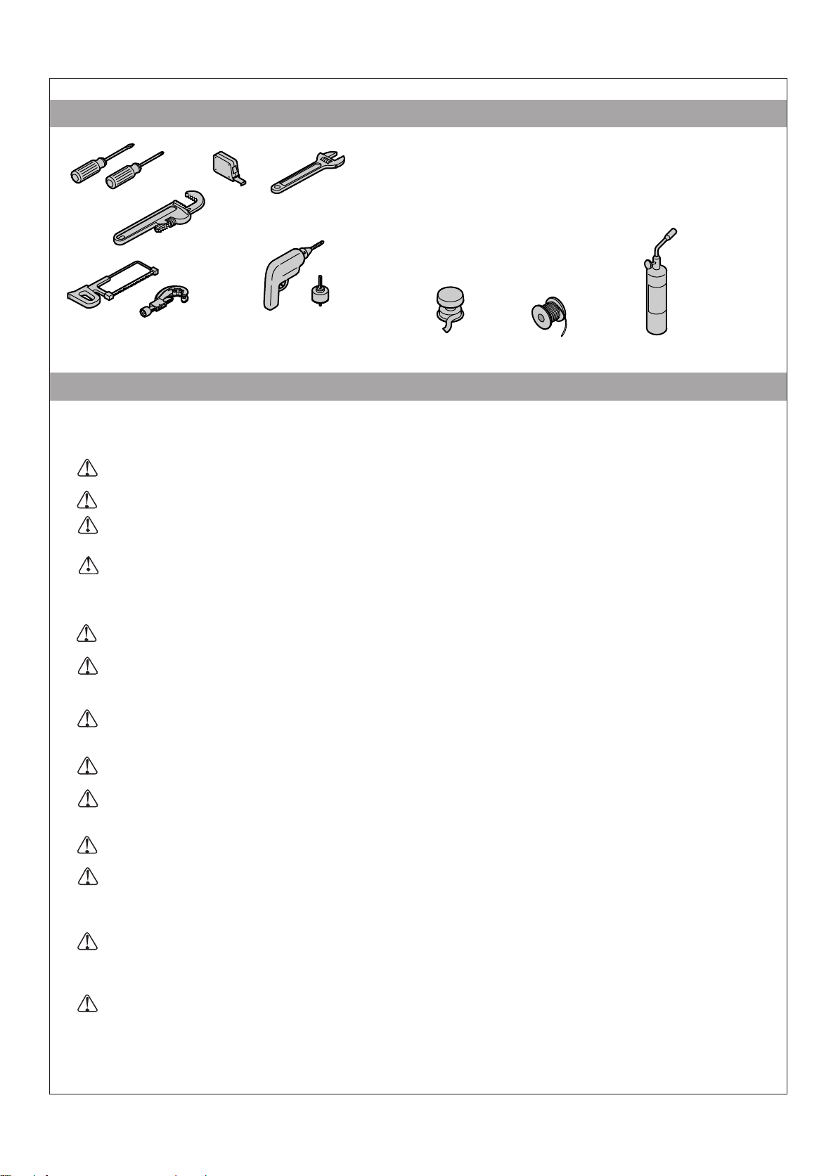
TOOLS AND MATERIALS
Plug:
·1/2" copper tubing
·Assorted copper fittings; G3/8", G1/2" and G3/4" copper
unions
·Wire Cutters or Wire Strippers
·Conventional woodworking tools and materials
·45 and 90 degree elbows
·Support Blocks (heat resistant)
Hacksaw or
Tube Cutter
Drill w/ 1-1/4" &
2-1/2" Hole Bit
Sealant Tape
Solder
Propane Torch
IMPORTANT SAFETY INSTRUCTIONS
This product complies with IEC EN 60335-2-53:2011 and EN 60335-1:2012/A11:2014.
Water Pressure: 0.14MPa~0.55MPa
IMPORTANT! When using this unit, basic precautions should always be followed.
DANGER: Risk of electrocution. Disconnect the electricity to the working area at the main breaker panel
before performing these installation steps.
WARNING: Risk of personal injury. If you become uncomfortable while taking a steam bath, you should
power off the unit. Cool off with the shower, open the door, or exit the unit.
WARNING: Risk of allergic reaction. Before adding any oils, aromatic therapies, or skin care products to
the aromatherapy well, make sure they will not cause an allergic reaction to the user.
WARNING: Risk of personal injury. This steam bath may not be suitable for use if you are pregnant, have
a heart condition, have high blood pressure, have circulatory problems, are under the influence of alcohol,
are taking drugs or are under the care of a physician. A steam bath can put undue stress on the body, as
does any hot bath, shower, or sauna.
WARNING: Risk of personal injury. The wet surfaces of steam enclosures may be slippery. Use care
when entering or leaving.
WARNING: Risk of personal injury. Prolonged use of the steam system can raise excessively the internal
human body temperature and impair the body’s ability to regulate its internal temperature (hyperthermia).
The appliance is to be continuously attended. Limit your use of steam to 10-20 minutes until you are certain
of your body’s reaction.
WARNING: Risk of personal injury. DO NOT consume alcoholic beverages or take medications/drugs
prior to or when using the steam bath. Alcohol and drugs affect mental judgement and inhibit bodily
functions such as heartbeat and respiration, resulting in potentially dangerous effects.
WARNING: Risk of injury to children. This appliance can be used by children aged from 8 years and
above and persons with reduced physical, sensory or mental capabilities or lack of experience and
knowledge if they have been given supervision or instruction concerning use of the appliance in a safe way
and understand the hazards involved. Children shall not play with the appliance. Cleaning and user
maintenance shall not be made by children without supervision.
WARNING: Risk of personal injury. Do not plumb a trap in the steam line or plumb the pressure relief
valve into the steam line. Plumbing the pressure relief valve into the steam line can be hazardous if the
steam outlet is capped.
WARNING: Risk of scalding. Do not touch the steam head during operation. The steam head is hot during
operation.
WARNING: Risk of personal injury. HYPERTHERMIA occurs when the internal temperature of the body
reaches a level several degrees above the normal body temperature of 37°C. The symptoms of
hyperthermia include an increase in the internal temperature of the body, dizziness, lethargy, drowsiness,
and fainting. The use of alcohol, drugs, or medication can greatly increase the risk of hyperthermia.
WARNING: Risk of personal injury or property damage. Avoid coming in contact with the water tank
and/or steam discharge line while the generator is operating or shortly after shutdown. Wear eye protection
and protective clothing when servicing the steam generator. The steam generator operates at high
temperatures.
WARNING: Risk of personal injury or property damage. DO NOT install the heating apparatus in the
steam enclosures.
NOTICE: If any heating apparatus(electric stove, bath heater etc.) is installed in the shower enclosure and both
the heater and steam generator is activated at the same time, the steam generator may malfunction due to heat of
the heating apparatus. Also, the heating apparatus could malfunction or be out of the order by steam of steam
generator.
1313992-T01-A
2
NOTICE: The warranty could not apply to damaged unit by reason of hard water condition. KOHLER Co.
recommend that water hardness should be less than 85mg/L.
NOTICE: Use this unit only for its intended use as specified in this manual. DO NOT use attachments not
recommended by Kohler Co.
NOTICE: Do not apply excessive heat to the generator connections when you solder connections. Do not apply
flux or acids directly to the generator, as damage to the seals, plastic components, and trim finish may result. Do
not apply petroleum-based lubricants to the generator components, as damage may result.
Inspect the product for any damage. Contact the KOHLER Customer Service Centre using the information on
the Compliance Certification.
Follow all local plumbing and electrical codes. All electrical work should be done by a qualified electrician.
Disconnect all power before making any electrical connections.
Kohler Co. reserves the right to make revisions in the design of products without notice, as specified in the
Price book.
SAVE THESE INSTRUCTIONS.
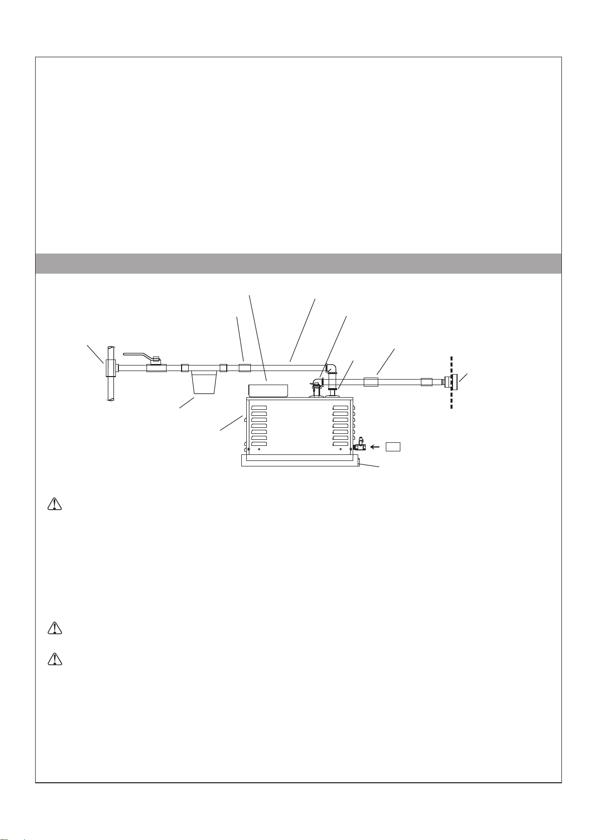
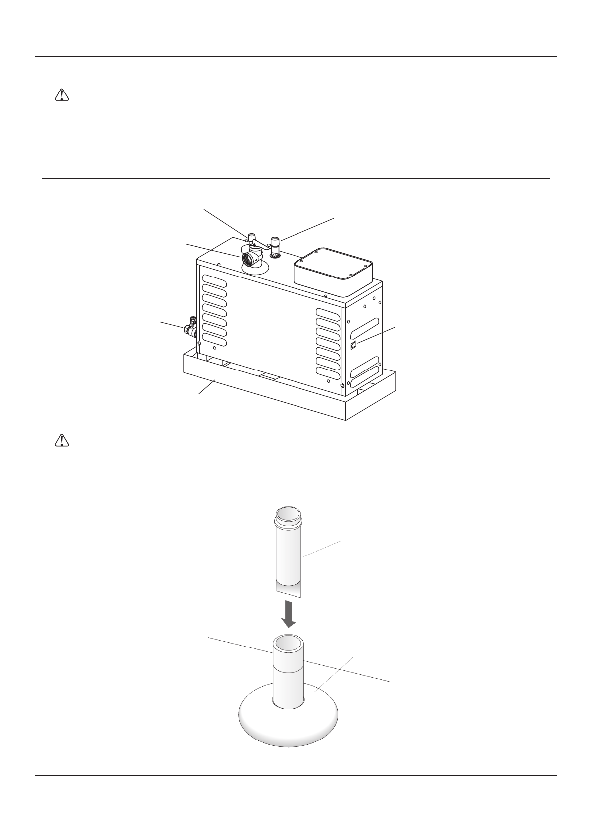
A. STEAM GENERATOR INSTALLATION
Tee
Field service box
Install copper union
in water feed line.
Shut-Off
C×F 3/8
Valve
Water Feed to Steam Generator
Pressure Relief Valve
Install copper union as close
Water
Inlet
as possible to steam generator.
C×F 1/2
Steam Head
Recommended In-Line
Water Filter
Control Cable Input
C×M 3/8
Drain Pan
1. Determine the Layout
WARNING: Risk of property damage. Allow a minimum of 30cm of air space around the steam generator
at all times. This provides an area for the heat generated by the unit to dissipate.
NOTICE: The steam generator will perform best when installed as close as possible to the steam head. The unit
should be installed within 7.6m of the steam head.
NOTICE: For optimum performance install the steam generator below the level of the steam head.
NOTE: When possible, use 45 degree elbows. Performance will be increased when 45 degree elbows are used.
Determine the location of the steam generator. Allow for a 30cm air gap on all sides of the generator. Allow for
a drain pan.
The steam generator have an integral drain pan.
2. Determine the Location of the Steam Hardware
WARNING: Risk of personal injury. Do not install the Steam Control User Interface outside the steam
enclosure. The User Interface must be installed within the enclosure to allow the sensors to regulate the
temperature and control the flow of steam. Refer to the Installation Guide for the Steam Control Kit.
WARNING: Risk of scalding. Do not block the steam head or locate it near a seat or bench, as the steam
head is hot during operation and may scald the user if touched.
Modules; Steam Head and Control Location
NOTE: All dimensions should be taken from the inside of the shower.
IMPORTANT! Do not install the steam control directly above or in-line with the steam head.
It is recommended to locate the steam head and the steam control on the same wall as the plumbing controls.
Locate the steam head 15.2cm above the shower floor and 12cm from the threshold.
Locate the steam control 150cm above the floor of the shower. Refer to the Steam Control Kit Installation
Instructions for more dimensional and installation information.
Make sure there is adequate clearance between the steam line and any surrounding surfaces.
3
1313992-70T-A
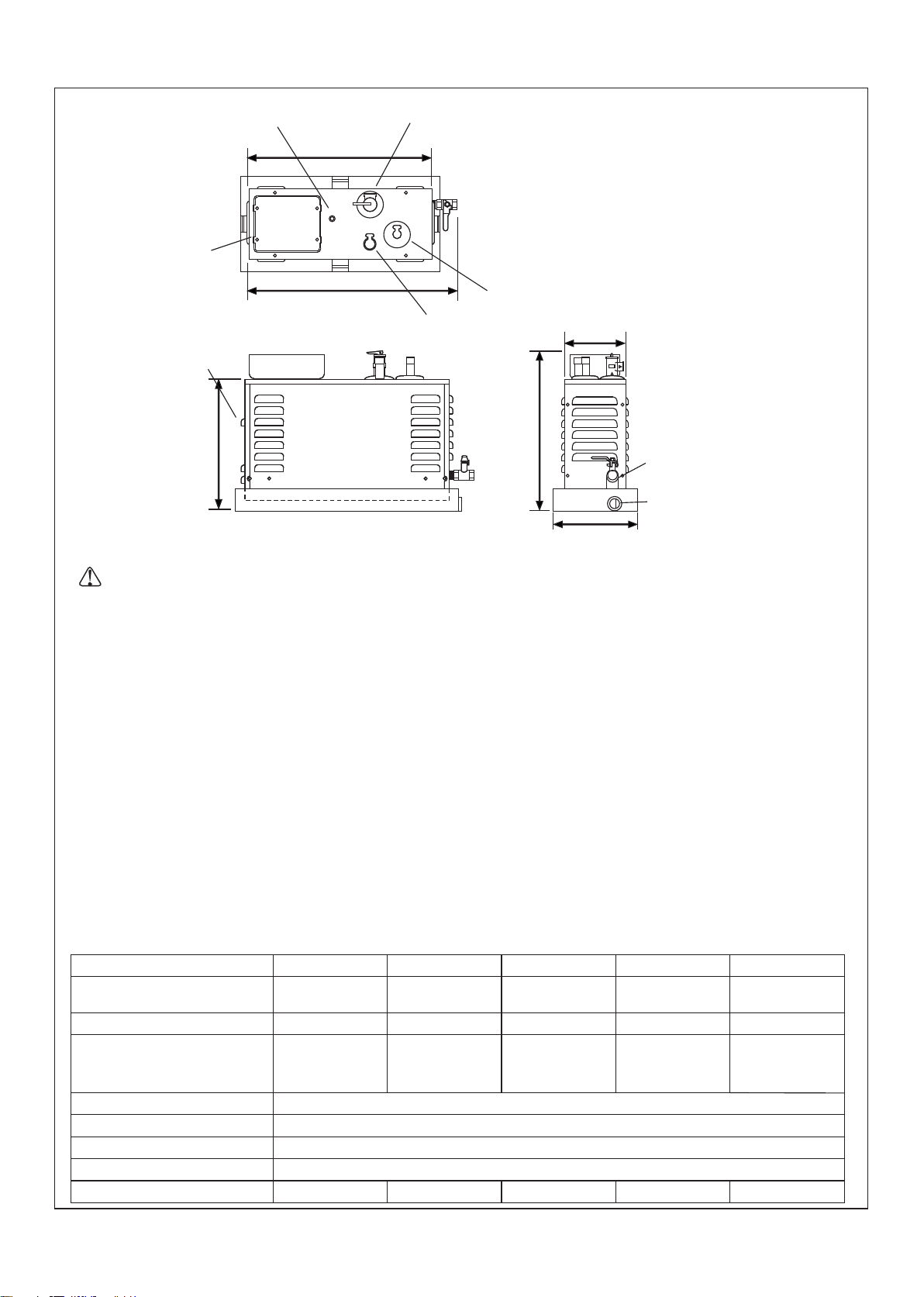
Green LED
Diagnostic Light
3/4" NPT
Pressure Relief
44.8cm
Minimum required access panel is
61cm L ×38cm H.
Allow for a minimum of 30cm of Space around
all sides of the steam generator.
The space between the generator and the drain
Field Wiring
pan was manufactured 1.9cm space.
Service Box
3/8" NPT Water inlet
15.6cm
Control
50cm
1/2" NPT Steam
Outlet
Cable Input
30.8cm
37.3cm
3/8" NPT Drain
3/4" NPT
21.3cm
3. Determine the Location of the Steam Generator
IMPORTANT! The minimum required access panel is 61cm L × 38cm H. Allow for a minimum 30cm
space around all sides of the steam generator. between the generator and the drain pan was The space
manufactured 1.9cm space.
A pilot lamp showing that the heater is switched on is to be installed in the attendant's room
Ensure clearance between the steam line and any surrounding surfaces.
Allow for access to the steam generator after installation.
Allow for a 30cm air gap on all sides of the generator.
For optimum performance, install the steam generator below the level of the steam head and as close as
possible to the steam head. The steam generator should be installed within 7.6m of the steam head in a dry,
well-ventilated area.
The minimum volume of the sauna room or cabin should be 2m
The minimum height of the sauna room or cabin should be 1.8m
The materials to be used for the walls and the ceiling of the sauna room or cabin should be waterproof
The installation of adjacent sauna heaters or a statement that the sauna heater or infrared emitter must be
2
used alone;
The connection and position of controls in the sauna room or cabin;
That thermostat sensors shall be installed so that they are not influenced by incoming air.
4. Install the Electrical Supply
Model
Generator - Dedicated
Circuit Required
Weight
Electrical Rating
Water Supply
Steam Line
Pressure Relief Valve (supplied)
Drain Line Valve
Sizing The Steam Room
1313992-70T-A
K-50205T-XT-NA
3.28 kW, 220-240V~,
20 A, 50-60Hz
220-240V~,
3.28kW
14.3A, 50-60Hz
1/2" copper line (3/8" NPT(F) to G1/2" Nipple Inlet(M))
1/2" copper line, (3/8" NPT(M) to G1/2"(M) Nipple Drain)
3
2.4m
K-5525T-XT-NA
5.95 kW, 220-240V~
40 A, 50-60Hz
5526T-XT-NA
K-
7.93 kW, 220-240V~
50 A, 50-60 Hz
K-5529T-XT-NA
9.92 kW, 220-240V~
60 A, 50-60 Hz
11.9kg 11.9kg 11.9kg 11.9kg11.9kg
220-240V~,
5.95kW
25.9A, 50-60Hz
220-240V~,
7.93kW
34.5A, 50-60Hz
220-240V~,
9.92kW
43.2A, 50-60Hz
1/2" copper line (1/2" NPT(M) to G1/2"(F))
3/4" NPT female thread(3/4" NPT(M) to G 3/4"(M))
2.4m
3
4.0m
3
6.8m
3
4
K-5531T-XT-NA
10.13 kW, 220-240V~
60 A, 50-60Hz
220-
240V~,
10.13kW
44.1A, 50-60Hz
3
9m
NOTICE: Each steam generator requires a dedicated circuit.
DANGER: Risk of electrocution. Disconnect the electricity to the working area at the main breaker panel
before performing these installation steps.
Follow all local electrical codes. All electrical work should be done by a qualified electrician.
Review the illustration showing specific Steam Generator Installation Requirements for your Steam Generator.
Install the appropriate electrical supply.
Maintain a 30cm space around the unit
Inlet
Steam Outlet
Pressure Relief Valve
Drain (install per
Applicable codes.)
Control Cable Input
Drain Pan
5. Install the Steam Generator
WARNING: Risk of property damage. Allow a minimum of 30cm of air space around the steam generator
at all times. This provides an area for the heat generated by the unit to dissipate.
NOTICE: For optimum performance, install the steam generator as close as possible to the steam head. The
steam generator must be installed within 7.6m of the steam head.
Water Inlet Screen
Inlet pipe
Insert the water inlet screen into the inlet pipe.(The water inlet screen is in the trouble shooting bag.)
5
1313992-70T-A
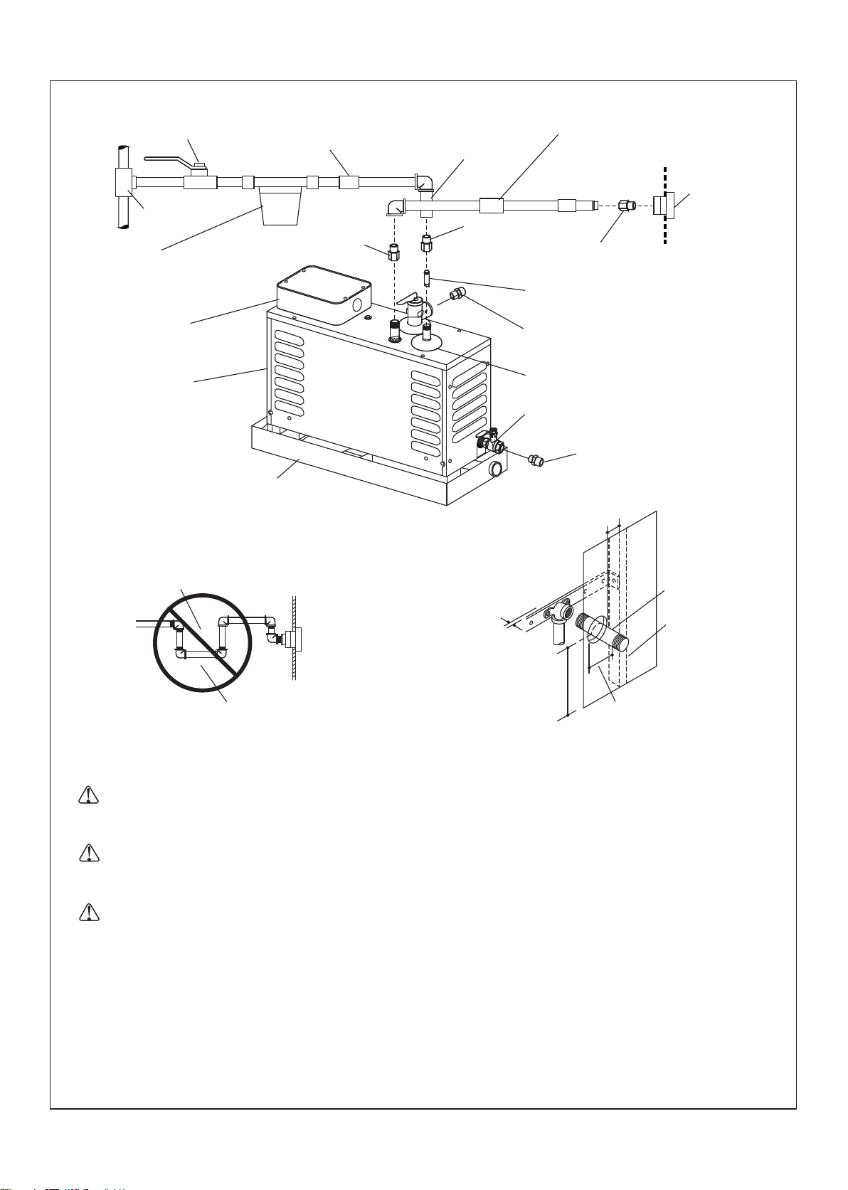
Shut-Off
Valve
Install copper union
in water feed line
Tee
Recommended In-Line
Water Filter
Water Feed to Steam
Generator (Pipe of Hose)
Nipple Outlet
(1/2" NPT(F)
to G 1/2"(M))
Nipple Pipe
(3/8" NPT(F) to
G 1/2"(M))
Inlet Water Screen
Install copper union as close
as possible to steam generator.
Steam
Head
Nipple Steam
(1/2" NPT(M) to G 1/2"(F))
Field Service
Box
Control Cable
Input
Steam Trap
Drain Pan
Provide clearance
from wall.
Do not run steam line down and then up.
This will create a steam trap.
Nipple Relief
(3/4" NPT(M) to G 3/4"(M))
Water Inlet
Drain Valve
(3/8" NPT(F))
Nipple Drain
(3/8" NPT(M) to G 1/2"(M))
2.5cm Min
Temporary
Nipple
Wall Stud
15.2cm
from floor
6.4cm
6. Install the Water Supply Line and Steam Line
WARNING: Risk of personal injury or property damage. Do not plumb the pressure relief valve into
the steam line. Plumbing the pressure relief valve into the steam line can create a hazard if the stteam
line is blocked or obstructed.
WARNING: Risk of scalding. Do not plumb a trap, shut-off valve, or pressure relief valve into the steam
line. Plumbing the pressure relief valve into the steam line can be hazardous, if the steam outlet is
capped.
WARNING: Risk of personal injury or property damage. Do not direct the pressure relief valve to the
enclosure. In the event the pressure relief valve activates, the hot water may spray causing burns to the
user and/or damage the enclosure. Therefore, the pressure relief valve should be directed to an area
where damage will not occur from contact with hot water and should conform to national and local
plumbing codes.
1313992-T01-A
6

Install the Water Supply Line to the Generator
NOTE: For all NPT threaded connections, use pipe tape or pipe sealant. Do not overtighten the fittings.
Connect to an existing cold water line, and run a 1/2" cold water line to a shut-off valve before the in-line
water filter.
Before final connection to the steam generator, flush out the water supply line into a large pail. This removes
any debris, silt, sand, or other material that may be in the line.
Install 1/2" copper tubing with a union fitting between the in-line water filter and the water inlet to the steam
generator.
Connect the water supply line to the steam generator.
Make sure that the water drain valve on the generator is closed.
Fill the steam generator with water and check for leaks.
NOTICE: Steam generators are equipped with an automatic shut-off. The water will stop after the unit is full. If
the water flows out of the steam outlet shut off the water and consult the "Troubleshooting Guide" or contact the
Customer Service Center using the number located on the Compliance Certification.
If the water supply line exceeds 3m or is exposed to cold areas, insulate the piping with appropriate
insulation.
Install the Steam Line
WARNING: Risk of scalding. Do not locate the steam head near a seat or bench or scalding may occur
upon contact with the steam head.
NOTICE: Never run the steam line down, then up. Running the steam line down and then up will create a steam
trap, blocking the flow of steam. The steam line should run up to the steam head from the steam generator, at a
pitch of 1cm to 1.3cm per 30.5cm of pipe.
NOTICE: Provide clearance between the back wall and the elbow leading into the steam housing. The elbow
must not contact any wall material.
NOTICE: Provide clearance between the steam line and surrounding surfaces.
NOTICE: Do not apply excessive heat to the generator connections when you solder connections. Do not apply
flux or acids directly to the steam generator, as damage to the seals, plastic components, and trim finish may
result. Do not apply petroleum-based lubricants to the steam generator components, as damage may result.
NOTE: For all the threaded connections, use thread sealant tape or pipe sealant. Do not overtighten the fittings.
NOTE: Use 1/2" copper tube for the steam line.
NOTE: Always install a unions/nipples fitting as close to the steam generator as possible.
Add blocking behind the desired steam head location.
Install and secure a G 1/2" elbow to the blocking directly behind the desired steam head location.
Cut a hole through the wall material to accept a temporary 1/2" copper tube nipple.
Add a temporary 1/2" copper tube nipple.
7
1313992-T01-A
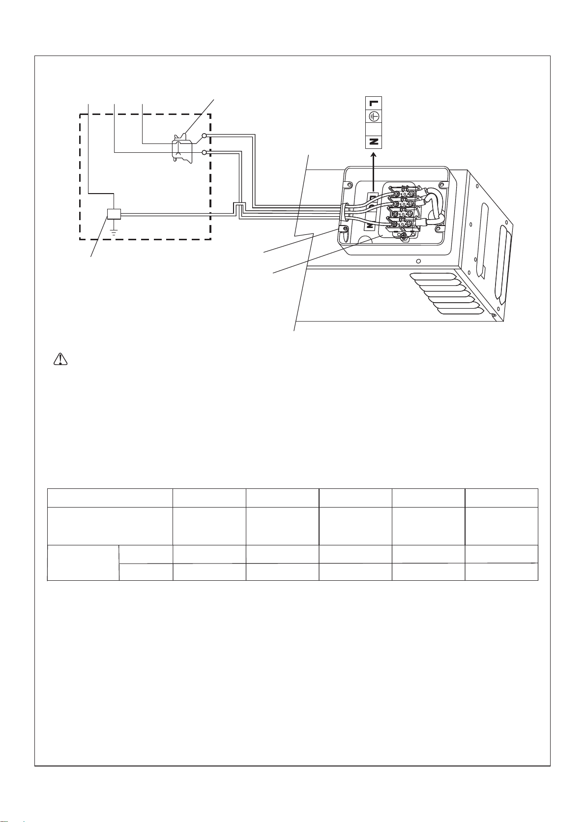
AC 220V 50Hz
Typical Two-Pole
GND
L
N
Breaker Box
Circuit Breaker
Equipment Ground
Junction Box
In Breaker Box
Field Wiring
7. Connect the Power
DANGER: Risk of electrocution. Disconnect all power before performing these installation steps.
NOTICE: All electrical work should be done by a qualified electrician.
NOTICE: All electrical wiring must be done in accordance with local codes.
NOTICE: Each steam generator requires a dedicated circuit.
NOTICE: The steam generator is not have a separate power supply. The power circuit breaker that meets the
specifications for each steam generator should be installed.
NOTICE: hardwired must be protected with heat insulating sleeve of an appropriate temperature rating.
Model
Generator - Dedicated
Circuit Required
Wire
Specifications
L, N
GND
K-50205T-XT-NA
3.28 kW,
220-240 V~,
20 A, 50-60 Hz
2.5mm
2.5mm
2
2
K-5525T-XT-NA
5.95 kW,
220-240 V~,
40 A, 50-60 Hz
2
4mm
2
4mm
K-5526T-XT-NA K-5529T-XT-NA
7.93 kW,
220-240 V~,
50 A, 50-60 Hz
2
6mm
2
6mm
9.92 kW,
220-240 V~,
60 A, 50-60 Hz
2
10mm
2
10mm
K-5531T-XT-NA
10.13 kW,
220-240 V~,
60 A, 50-60 Hz
2
10mm
2
10mm
Connect the Power
Turn off all electricity to the working area at the main circuit breaker panel.
Open the steam generator field service box (Junction box) located on top of the steam generator.
Unscrew the screws of the terminals for field wiring on the terminal block located in the junction box.
Connect 220-240V~ electrical lines to their respective terminals, securing them in place by tightening the
screws.
Close the junction box.
Turn on the main power.
The function light should display a green light. If the function light is not green, consult the "Troubleshooting
Guide" or contact the Customer Service Center using the number located on the Compliance Certification.
1313992-T01-A
8
8.
Complete the Installation
1
Install the steam housing and steam head following the Steam Control Kit instructions.
1
Install the steam control following the Steam Control Kit instructions.
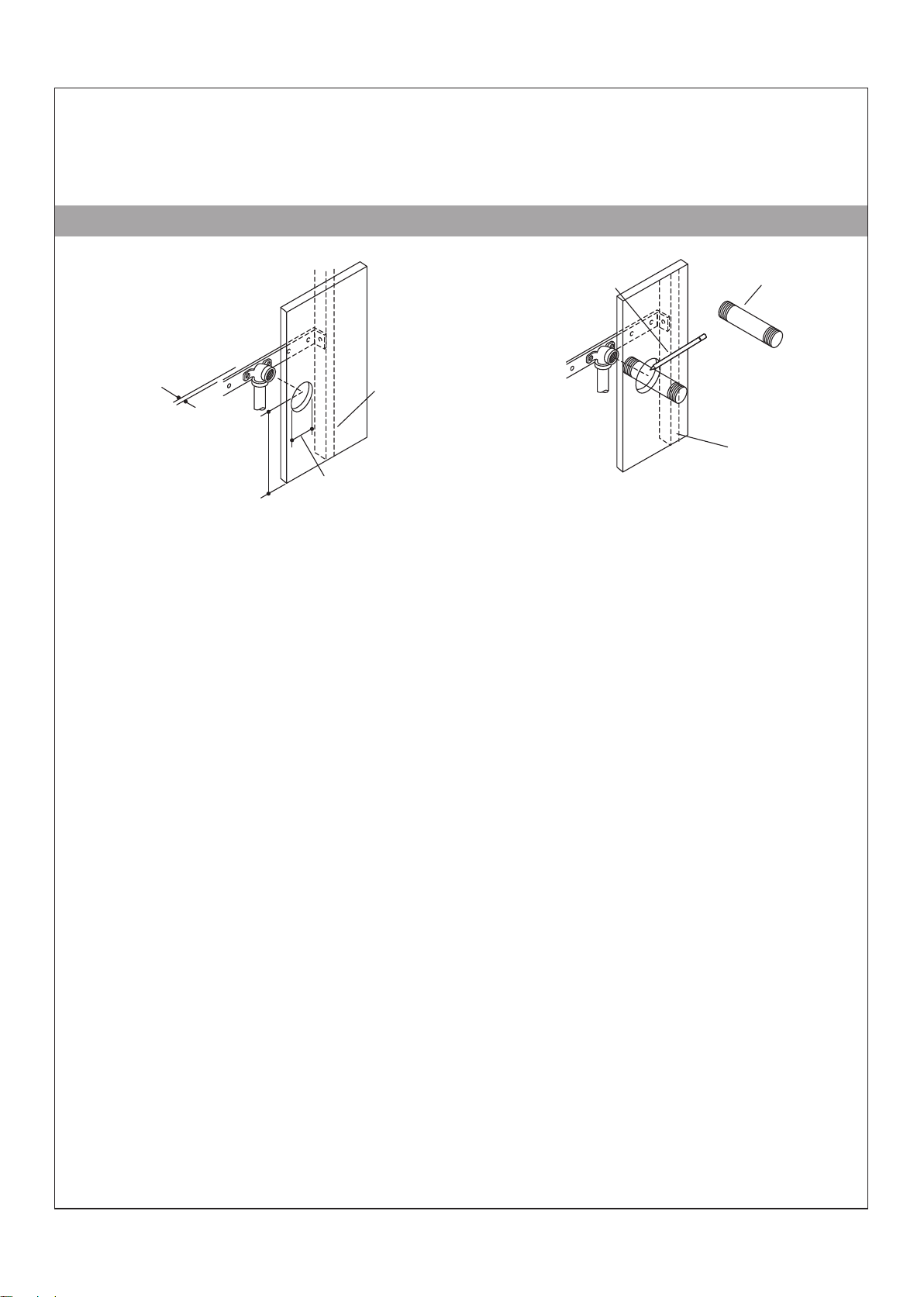
B. STEAM CONTROL KIT INSTALLATION
Mark the nipple even
with finished wall.
Provide clearance
from wall.
15.2 cm
from floor
6.4cm
1. Prepare the Site
NOTE:
to the steam generator installation instructions guide for more information, if required.
NOTE:
steam heads do not need to be located in the same area.
1
1
1
1
This section continues the installation as described in the steam generator installation instructions. Refer
If two steam heads are required, ensure there is at least 32cm between the center of each hole. The
Install the finished wall material.
Mark the temporary pipe nipple at the location of the finished wall surface.
Remove the temporary pipe nipple from the elbow.
Drill or cut a 6.4 cm hole centered around the elbow in the wall.
Wall Stud
Temporary Nipple
Wall Stud
9
1313992-T01-A
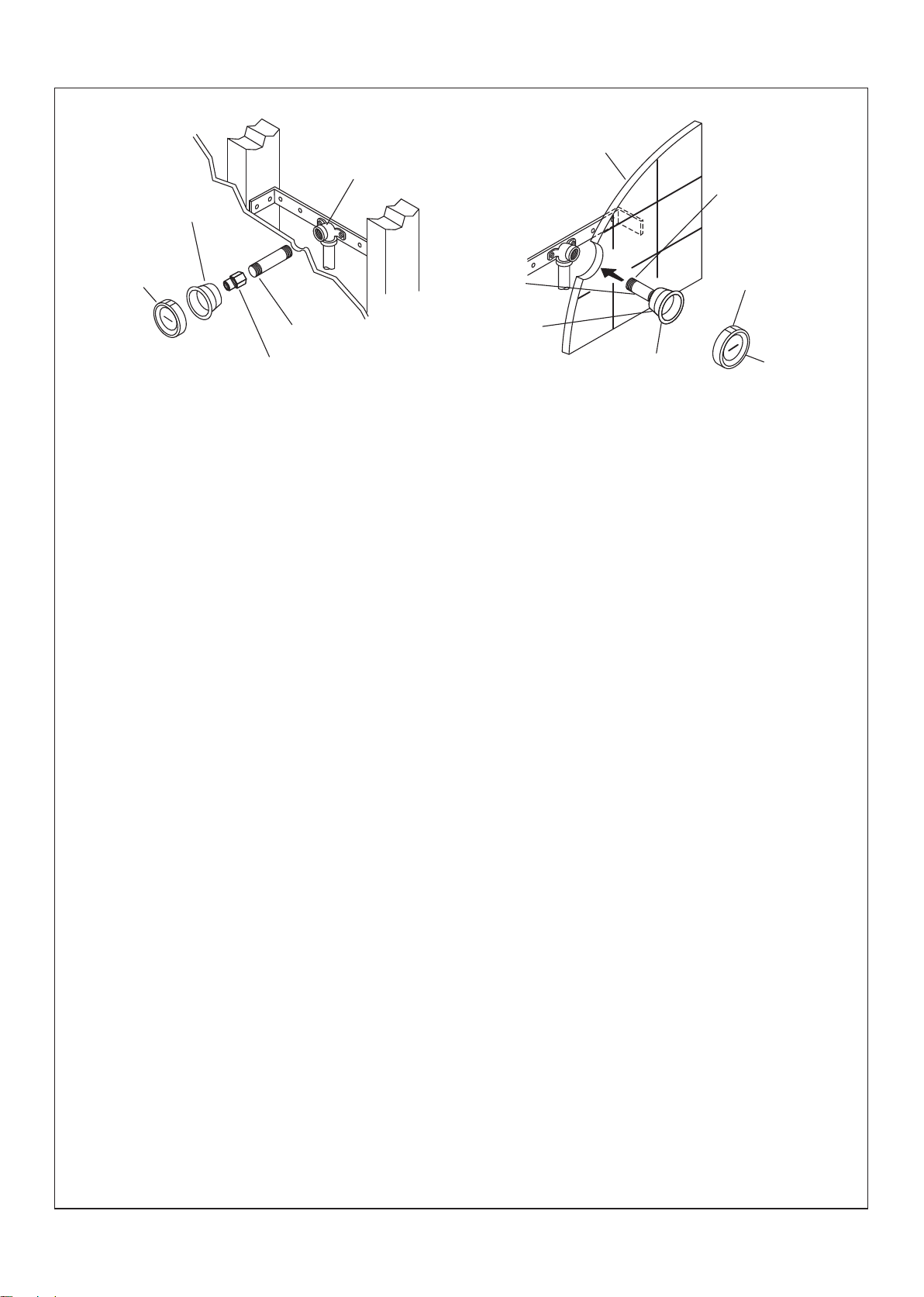
Steaming Housing
G 1/2"
Elbow
Wall
Apply
thread sealant
Steam head
Apply thread sealant
Nipple Steam
(1/2" NPT(M) to G 1/2"(F))
2. Install the Steam Head(s)
NOTICE: Do not obstruct the steam head with shut-off valves, plugs, or caps.
Subtract 3.2cm from the marked length to determine the appropriate nipple size.
1
Choose a nipple length within 3.8cm of the appropriate nipple size.
1
Apply thread sealant to the threads on one side of the nipple and thread that side into the steam head
1
housing until hand-tight.
Apply thread sealant to the threads on the other end of the nipple.
1
Position the gasket around the steam head housing so that it will be between the finished wall and the steam
1
head housing flange.
Use a 1" socket to thread the steam head housing assembly into the elbow in the wall.
1
Make sure the gasket is compressed and a good seal has been achieved around the edges of the steam
1
head housing.
Nipple
Steaming
Housing
Lip
Aromatherapy
Well
Steam
head
Use an appropriate sealant to achieve a watertight seal if needed.
1
Press the steam head assembly into the steam head housing with the aromatherapy well positioned on the
1
top of the steam head.
1313992-T01-A
10
 Loading...