

Kohler K-1913 Installation Manual
Installation Guide
Rising Wall Bath
K-1913
M product numbers are for Mexico (i.e. K-12345M)
Los números de productos seguidos de M corresponden a México
(Ej. K-12345M)
Français, page ″Français-1″
Español, página ″Español-1″
1128532-2-G
Important Information
WARNING: Risk of injury or property damage. Please read all instructions thoroughly before
beginning installation, including the following requirements.
WARNING: When using electrical products, basic precautions should always be followed,
including the following:
DANGER: Risk of electric shock. Connect only to circuits protected by a Ground-Fault
Circuit-Interrupter (GFCI) or Residual Current Device (RCD).
WARNING: Unauthorized modification may cause unsafe operation and poor performance of
the product. Do not relocate the components, or make other modifications to the system other than
those specified in this document, as this could adversely affect the performance and safe operation.
Kohler Co. shall not be liable under its warranty or otherwise for personal injury or damage caused
by any such unauthorized modification.
Building materials and wiring should be routed away from heat-producing components.
Install to permit access for servicing.
Grounding is required. The unit should be installed by a qualified service representative, and grounded.
WARNING: Risk of electric shock. A licensed electrician should make all electrical connections.
1128532-2-G 2 Kohler Co.
Important Information (cont.)
WARNING: Risk of electric shock. Disconnect power before servicing.
NOTICE: Follow all local plumbing and electrical codes.
Table of Contents
Important Information .............................................................. 2
Tools and Materials ............................................................... 3
Before You Begin ................................................................. 4
Parts Identification ................................................................ 5
Construct the Framing ............................................................. 6
Confirm the Correct Cutout .......................................................... 8
Install the Drain Lines and Rough Plumbing ............................................. 9
Remove the Shipping Brackets ...................................................... 11
Remove the Door ................................................................ 12
Remove the Pulley Assemblies and Mounting Brackets .................................... 14
Remove the Receptor Tray ......................................................... 16
Disconnect the Components ........................................................ 17
Position the Bath ................................................................ 18
Level and Secure the Bath ......................................................... 20
Attach the Water Supply to the Accumulator ............................................ 21
Install the Receptor Tray, and Connect the Drains ........................................ 22
Install the Mounting Brackets and Pulley Assemblies ...................................... 24
Install the Door ................................................................. 26
Attach the Counterweights ......................................................... 27
Connect the Components .......................................................... 29
Adjust the Bath Door ............................................................. 30
Seal/Drain System Electrical Connections .............................................. 32
Heated Surface Electrical Connections (if equipped) ...................................... 34
Confirm Heated Surface Operation (if equipped) ......................................... 35
Install the Trim Caps and Access Panel ............................................... 36
Install the Finished Wall ........................................................... 38
Troubleshooting ................................................................. 38
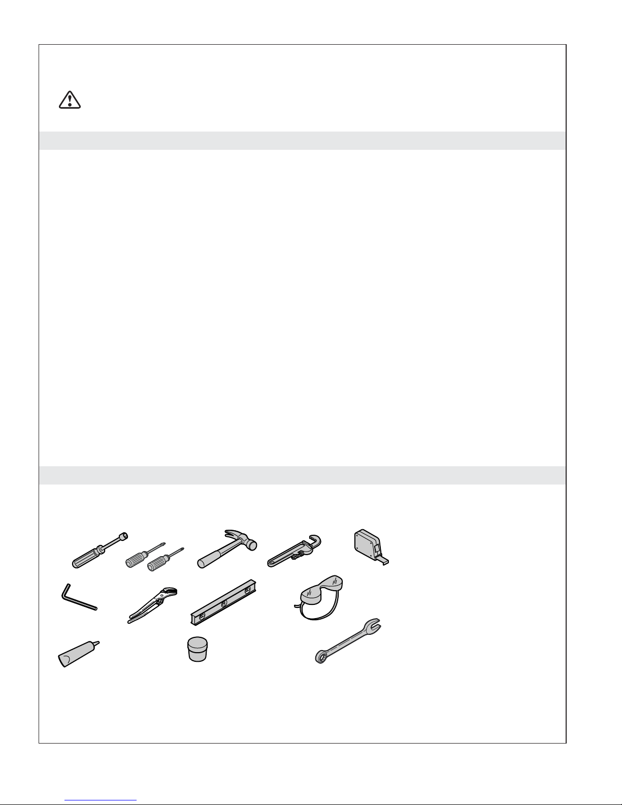
Tools and Materials
Plus:
• Crowbar or small
pry bar
• Metal Shims
• Masking Tape
• Pencil
Hex Wrenches
Silicone
Sealant
Kohler Co. 3 1128532-2-G
Removable
Bolt Adhesive
7/16", 9/16" and 7/8"
Open-end wrenches
• Drop cloth or
protective material
• Standard wood working tools
and materials

Before You Begin
NOTICE: Risk of personal injury. Handle the bath and frame carefully. Some edges may be sharp or
rough.
NOTICE: Risk of product damage. Handle the bath and frame carefully. The bath will break or
malfunction if handled carelessly.
NOTICE: Risk of product damage. Do not support the weight of the bath by the perimeter of the rim. To
avoid damage to the product, support the bath by its base or feet.
NOTICE: Risk of product damage and personal injury. Due to the weight and installation difficulty of
the product, Kohler Co. recommends that two people perform this installation. There are several
installation sequences that are very difficult if performed alone.
IMPORTANT! Use care when removing screws. All screws will be reused unless otherwise indicated. Do
not strip the heads.
IMPORTANT! Do not cut or remove any cable ties unless instructed. They are used to hold critical parts
in place, and are designed to stay in place throughout the installation.
IMPORTANT! If the installation site is in an area where frequent or prolonged power outages occur,
Kohler Co. recommends that a minimum 350 VA Uninterruptible Power Supply (UPS) be installed as a
backup power source to the bath controller. The UPS will ensure that door functionality is not
compromised in the event of a power outage.
Follow all local plumbing and electrical codes.
Depending on the installation, it may be necessary to disassemble parts of the bath to pass
through all doorways, hallways, and stairways between the staging area and the bathroom. There
will be several points in this installation where the installer will be asked if further disassembly
is required. All adjustments have been made at the factory. Installation time is less for jobs
requiring little or no disassembly.
IMPORTANT! Save all hardware. If disassembly is required, save and organize all hardware. Hardware
will be reused unless otherwise specified.
There are supplemental installation instructions located on the back of the access panel.
This bath requires three drains with separate P-traps. Allow for three drains connecting at the
stack in your installation.
The installation instructions outline the only parts that need to be removed or disassembled during
the installation process. Although many parts may appear to be removable, do not disassemble
anything unless instructed.
Unpack the bath in an open area.
Inspect the unit for damage and make sure parts such as counterweights, access panel, and trim
caps are accounted for. The unit shown in this manual has a left-hand drain and may appear
different than the unit you have purchased.
1128532-2-G 4 Kohler Co.
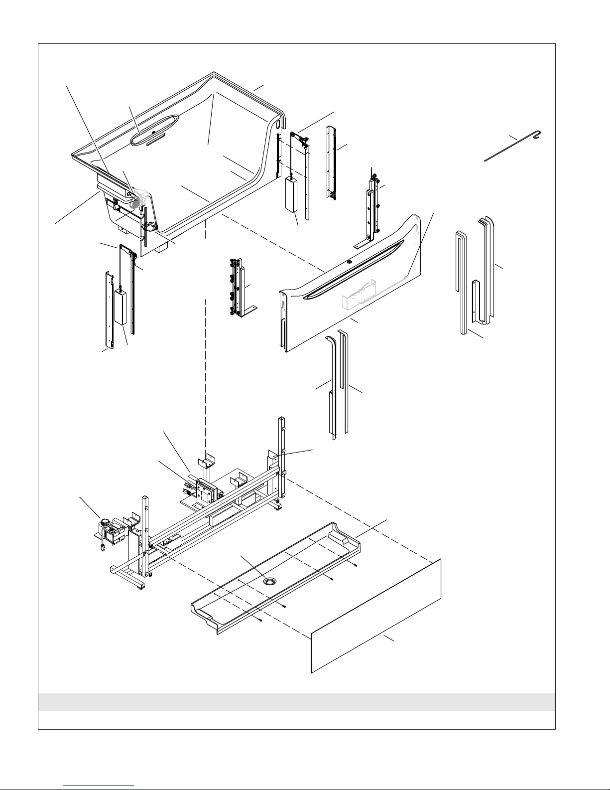
Fill Spout/Accumulator
Grab Bar
Bath
(Left Hand Drain shown)
Pulley Assembly (RH)
(includes limit switch and bumper)
Accumulator
Pulley (LH)
Assembly
(includes limit
switch and
bumper)
Mounting
Bracket
Controller
(Power Supply)
Second (Sidewall)
Drain Opening
Primary Footwell
Bath Drain
Bumper
Counterweight
Roller
Assembly
(LH)
Trim Cap
Wall (LH)
Mounting Bracket
Counterweight
Roller Assembly (RH)
Power Connection for Door
(always opposite footwell drain side)
Door Assembly
(includes electronics
and brush seal)
Trim Cap Cover (LH)
Guide Tool
Trim Cap
Wall (RH)
Trim Cap
Cover (RH)
Product ID Label
Drain Valve for
Secondary Drain
Support
Frame
Parts Identification
Counterweight Guide
Receptor Tray
Receptor Tray
Drain
Access Panel
Kohler Co. 5 1128532-2-G
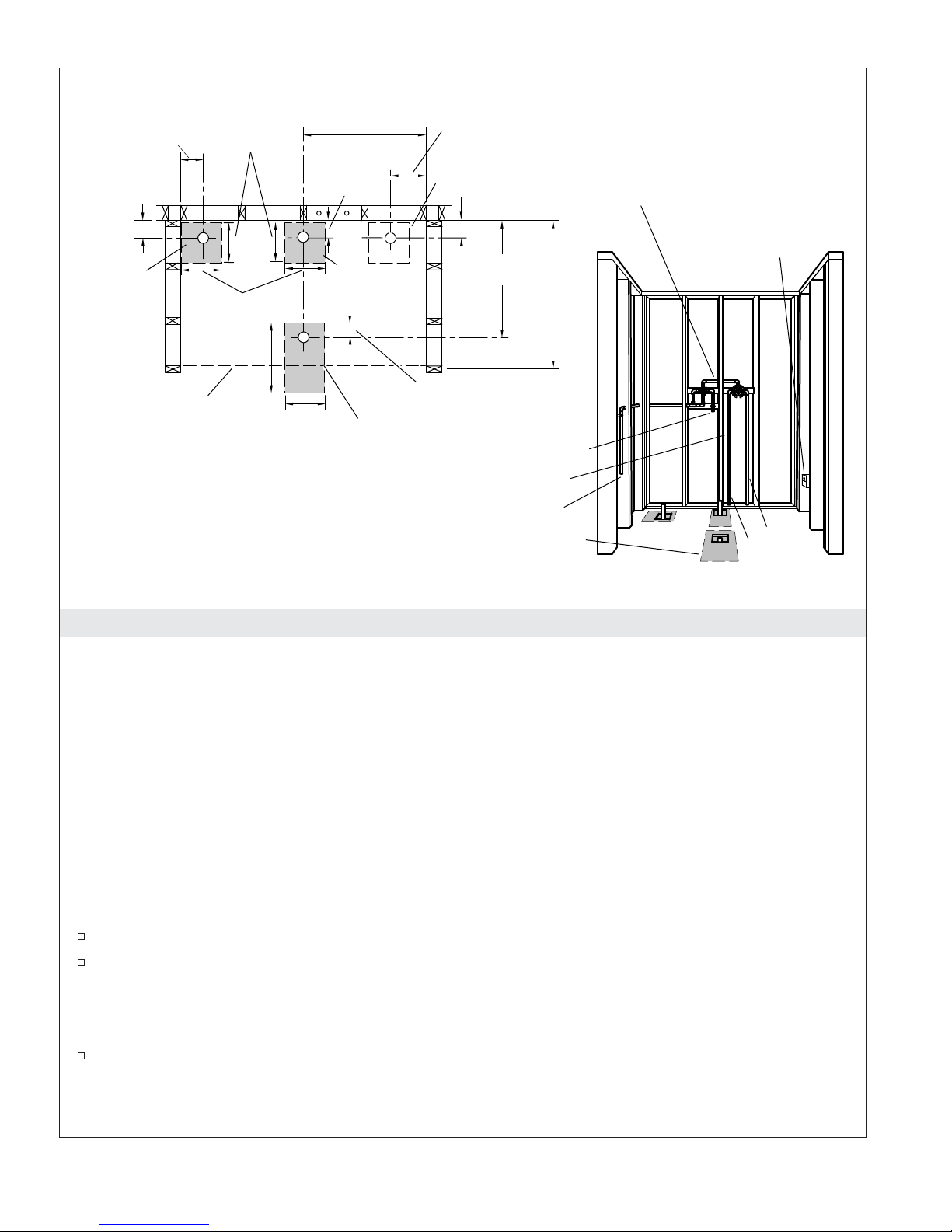
7-3/4" (197 mm)
Three Drain Cutouts (required)
30" (762 mm)
10" (254 mm)
9-3/4"
(248 mm)
Construct 2x4 or 2x6 stud
framing according to
the roughing-in information.
3-7/8"
(98 mm)
1
(LH) Drain
Cutout
Front Edge of
Receptor Tray
Floor Plan for Left-Hand Drain Model
10" (254 mm)
16"
(406 mm)
10" (254 mm)
2
3
3-1/2"
(89 mm)
Drain
Cutout
Drain Cutout
(RH) Drain Cutout
3-7/8" (98 mm
1
5-1/2" (140 mm)
24-1/2"
(622 mm)
Position the rough plumbing.
To Accumulator
Verify that the subfloor offers adequate support, and is flat and level.
33-1/4"
(845 mm)
To Handshower
Drain Access
Plumbing configuration
may vary.
GFCI Protected Outlet
(Opposite Side of
Accumulator Supply)
Cold
Hot
1. Construct the Framing
All Installations
NOTICE: Measure your product for site preparation. Note the model number located on the blower
motor, then visit the product page at www.kohler.com for more information.
NOTICE: Adequate floor support must be provided.
NOTICE: Do not support the weight of the bath by the perimeter of the rim. To avoid damage to the
product, support the bath by its base or feet.
IMPORTANT! This product requires three 1-1/2″ diameter drain outlets, three P-traps, and three separate
lines to the stack. In an ideal configuration, none of the drains should be combined, as performance may
suffer and the potential for backflow will increase. If required, the two bathing vessel drains (#1 and #2 in
diagram) may be combined downstream from the P-traps into a single 3″ diameter drain line.
IMPORTANT! The drain for the receptor tray (#3) requires a dedicated P-trap and stack connection.
Follow all local plumbing and electrical codes.
Leave the stud pocket open and do not install the finished wall until after the bath has been
installed. This installation is best done with access from the backside of the studs, particularly from
each side.
NOTICE: Follow all local plumbing and electrical codes.
If the installation site is in an area where frequent or prolonged power outages occur, Kohler Co.
recommends that a minimum 350 VA Uninteruptable Power Source (UPS) be installed as a backup
power source for the bath controller. This will ensure the door will open in the event of a power
outage.
1128532-2-G 6 Kohler Co.
Construct the Framing (cont.)
Install a 120 V, 15 A, 60 Hz electrical outlet protected by a GFCI or RCD. The outlet must be located
on the side of the bath opposite the footwell drain outlet, within 24″ (610 mm) of the controller).
Units with the heated surface feature will require a second electrical outlet within 24″ (610 mm) of
the heated surface controller.
NOTE: Drain #1 is the sidewall drain/valve outlet. Drain #2 is the overflow and footwell drain outlet.
Drain #3 is the receptor tray drain outlet.
NOTE: Three drains are required for this product. Drains #1 and #2 require a 10″ (254 mm) x 10″ (254
mm) cutout.
NOTE: Drain #3, the receptor tray drain, requires a 10″ (254 mm) x 10″ (254 mm) cutout if access from
below is available. If above-the floor access is required to make the connections, a 10″ (254 mm) x 16″ (406
mm) cutout is required to allow access. The 10″ (254 mm) wide cutout is critical to prevent subfloor
contact with the drain area of the receptor tray. If the subfloor and drain come into contact, enlarge the
cutout as needed or raise the bath using the adjustable feet. The receptor tray must be level and the drain
must rest comfortably through the subfloor.
Make sure the flooring offers adequate support for the bath, and verify that the subfloor is flat and
level.
The bath should be installed in an alcove installation. Construct a 2x4 or 2x6 frame.
Position the plumbing. Cap the supplies, and check for leaks.
Provide adequate ventilation and at least 15 cubic feet (.4 cubic meters) of open air space for cooling
the motor and supplying sufficient air to the blower. Do not install the blower motor closer than 1″
(25 mm) to the wall or other objects.
IMPORTANT! Use the chart below as a general guideline. Every installation varies. Hallways, corners,
stairways and other obstacles should be taken into account when determining how much disassembly is
required. Avoid unnecessary disassembly when possible.
Door Opening Recommended Installation Action
Larger than 33″ (838 mm) No disassembly is required. Skip sections 4
through 8.
31″ (787 mm) to 33″ (838 mm) Remove the door from the bath and the
receptor from the support frame.
30″ (762 mm) to 31″ (787 mm) Full disassembly is likely. Follow all steps in
this manual.
Less than 30″ (762 mm) The door open needs to be enlarged to a
minimum of 31″ (762 mm).
Kohler Co. 7 1128532-2-G
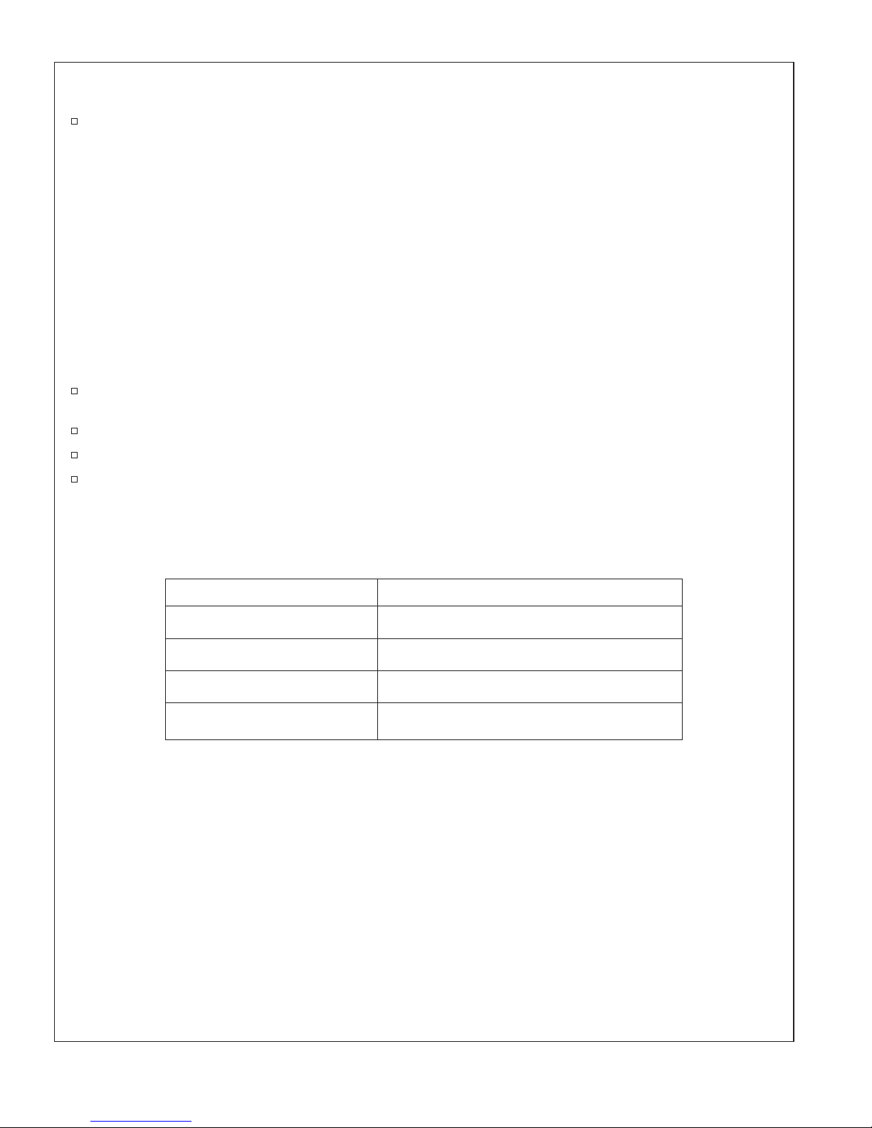
10" (254 mm)
Receptor Drain Cutout
Front Edge of
10"
(254 mm)
16"
(406 mm)
Receptor Tray
1/4" (6 mm)
16" (406 mm)
Subfloor
2. Confirm the Correct Cutout
All Installations
NOTE: Drain #3, the receptor tray drain, requires a 10″ (254 mm) x 10″ (254 mm) cutout if access from
below is available. If above-the floor access is required to make the connections, a 10″ (254 mm) x 16″ (406
mm) cutout is required to allow access. The 10″ (254 mm) wide cutout is critical to prevent subfloor
contact with the drain area of the receptor tray. If the subfloor and drain come into contact, enlarge the
cutout as needed or raise the bath using the adjustable feet. The receptor tray must be level and the drain
must rest comfortably through the subfloor.
Measure the cutout to confirm it is a minimum of 10″ (254 mm) wide and 16″ (406 mm) long.
Study the illustrations at the right. When the cutout is the correct size, the drain outlet on the
receptor tray and the surrounding material will not come in contact with the subfloor. The drain
outlet will protrude into the cutout when installed.
If the cutout is too small, the receptor tray will be too high. The counterweights will strike the
receptor tray when the door is raised and the door seals will not inflate.
1128532-2-G 8 Kohler Co.
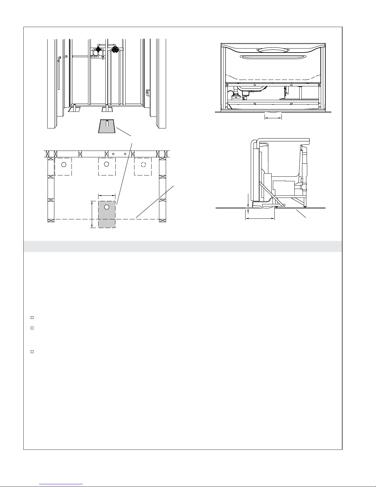
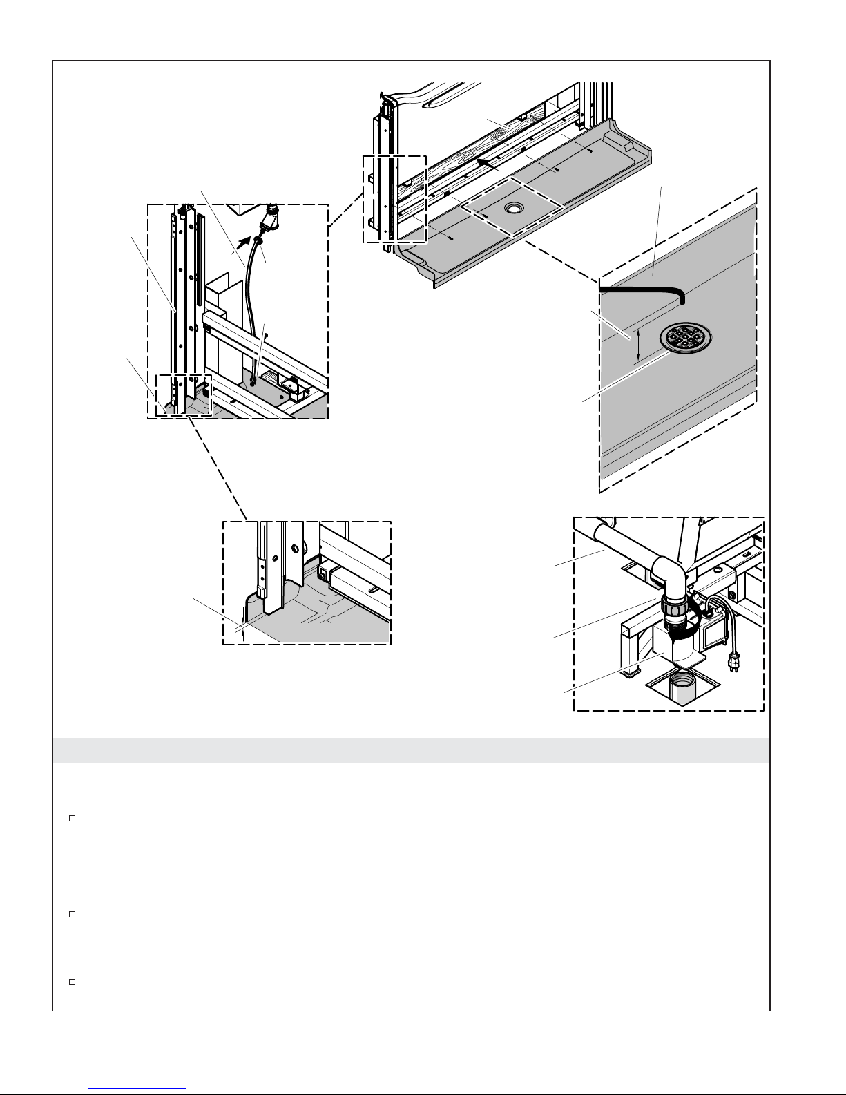
Install the drain lines.
46" (1168 mm) From Subfloor Recommended
Transfer Valve
To
Handshower
To
Accumulator
Sidewall
Bath Drain
Receptor Tray Drain
Recommended Plumbing Configuration for Left-Hand Models
Mixing Valve
2
1
3
Flush out the drains.
Slotted
Overflow Drain
Accumulator
Fitting (supplied)
3/4" NPT
Install water accumulator line.
(not supplied)
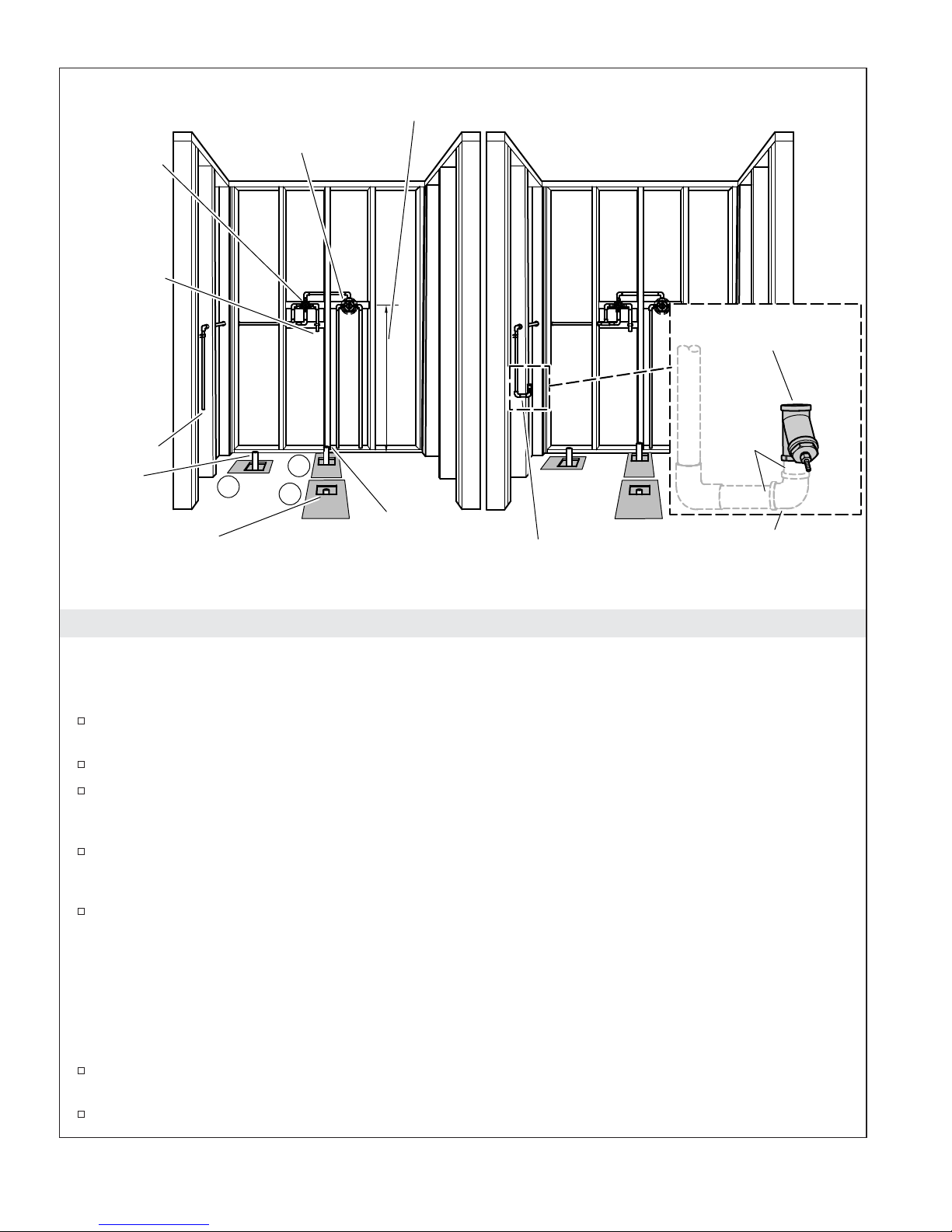
3. Install the Drain Lines and Rough Plumbing
All Installations
Plumbing Access Considerations
Confirm adequate mounting and connection space exists for the faucet specified for your
installation.
Confirm adequate clearance for three P-traps.
If the unit is installed on a slab at a corner of the outside walls: Make connections to the
accessible end, or provide access to the plumbing connections if not able to do so through the front
access panel. Check the P-trap clearance for drains #1 and #2.
If the unit is installed on a slab back-to-back against the outside walls: Plan to provide adequate
access to the plumbing connections. Limited access is available through the access panel. Check the
P-trap clearance for drains #1 and #2.
When the unit is installed where the drain connections are accessible from below: Connections
can usually be made from underneath the unit.
Install the Rough Plumbing
IMPORTANT! This product requires three 1-1/2″ diameter drain outlets, three P-traps, and three separate
lines to the stack. In an ideal configuration, none of the drains should be combined, as performance may
suffer and the potential for backflow will increase. If desired, the two bathing vessel drains (#1 and #2)
may be combined downstream from the P-traps into a single 3″ or larger drain line.
Install the plumbing lines following the valve and trim manufacturer’s instructions. Recommended
supply fittings and locations are shown above.
Use 3/4″ valves for optimal fill time.
Kohler Co. 9 1128532-2-G

Install the Drain Lines and Rough Plumbing (cont.)
Install the receptor tray drain line and P-trap.
Install the sidewall drain line and P-trap.
Install the slotted overflow drain line and P-trap.
Install the water supply line which will connect to the accumulator. Do not connect at this time.
1128532-2-G 10 Kohler Co.
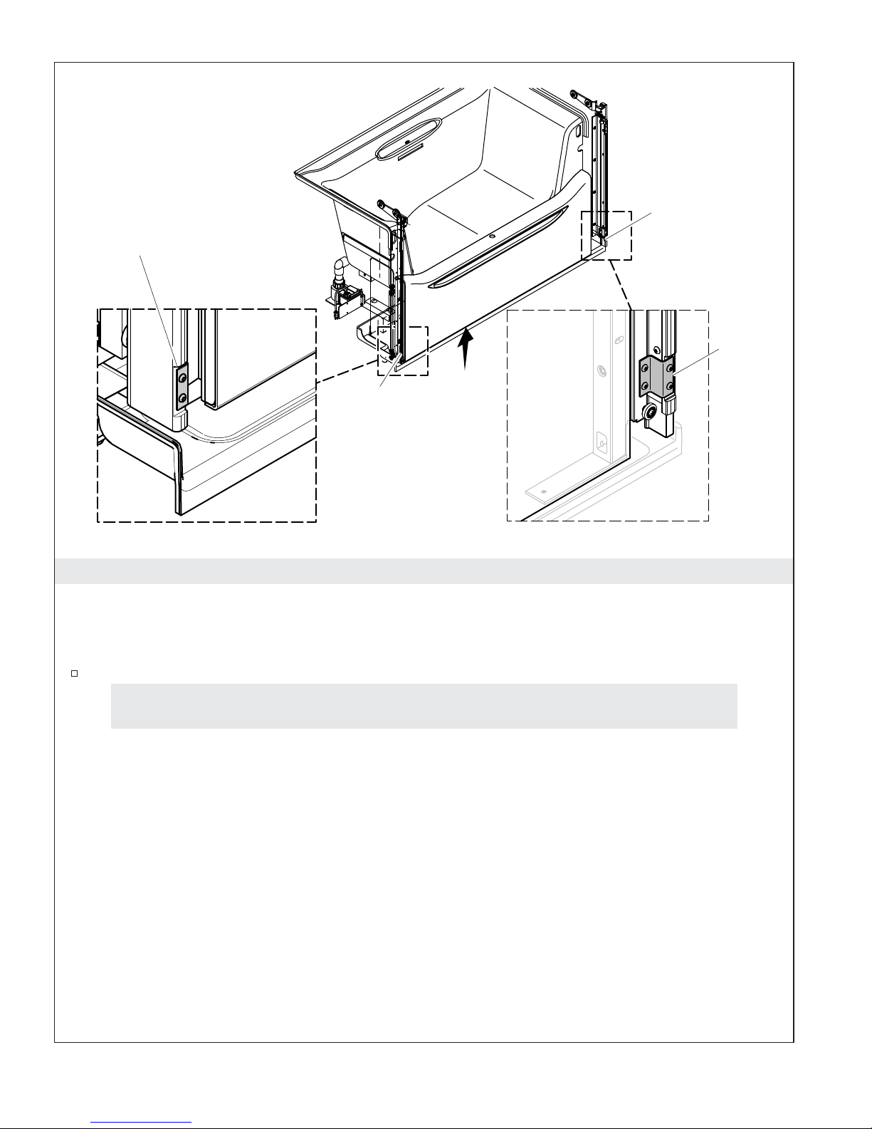
Left Shipping
Bracket
Bracket
Location
4. Remove the Shipping Brackets
All Installations
Bracket
Location
Right
Shipping
Bracket
NOTE: Refer to the diagram in the ″Product Identification″ section to identify major components when
needed.
Remove and discard the shipping brackets. Take care not to strip the screw heads.
If the bath can be moved into place without disassembling it, go directly to the ″Position
the Bath″ section.
Kohler Co. 11 1128532-2-G
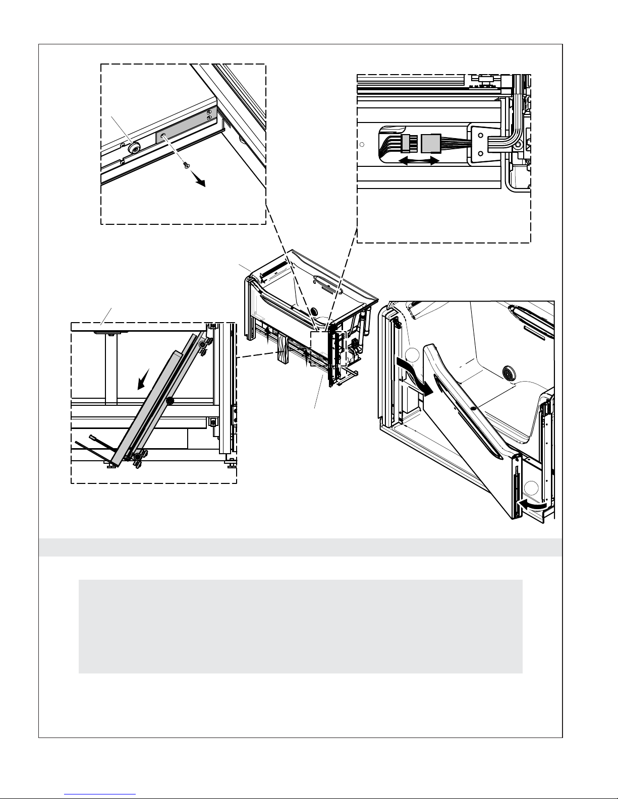
Rubber
Door Stop
Remove screw.
Bottom View of Door Opposite Drain
Drain End
Bath Door
Remove roller assembly.
Disconnect door
power cord.
Bottom View of Door Opposite Drain
2
Side Opposite
Drain
Remove the door.
1
5. Remove the Door
Installations Requiring Disassembly Only
Disassembly Checkpoint #1
The steps in this section may not be necessary. Make sure removing the door is required.
The bath can sometimes be moved into place fully assembled.
If the bath can be moved into place without performing these steps, go directly to
″Position the Bath.″
Remove the Door
CAUTION: The door will be heavy and difficult to lift until the counterweights are installed.
1128532-2-G 12 Kohler Co.

Remove the Door (cont.)
IMPORTANT! Cover the receptor tray with protective material to avoid damaging it.
Raise and latch the door.
Have the second installer hold the door up and brace it using a 2x4 under the door, with the bottom
end of the 2x4 positioned on the subfloor (not the receptor tray).
CAUTION: Risk of personal injury. When the screw is removed from the roller assembly plate,
friction is the only force holding the roller assembly in place. To avoid injury or damage to the
bath, make sure the roller assembly does not fall.
On the side of the door opposite the drain and fill spout, carefully remove the screw nearest the
rubber door stop securing the cover plate and roller assembly on the bottom of the door. Take care
not to strip the screw heads.
Slide the roller assembly down 2″ (51 mm) to 4″ (102 mm). If it sticks, gently pry or tap the roller
assembly from above to help lower it.
Unplug the power cord from the inside of the door by reaching up into the recess that the plate
covered.
Remove the power cord from the door, then slide the roller assembly all the way down, leaving it
intact. Further disassembly of the cord from the roller assembly is possible but typically not needed.
IMPORTANT! Do not cut the cable ties securing the power cord to the roller assembly.
NOTE: The power cord is held in place by a bracket at the base of the roller assembly. Do not remove the
bracket unless necessary.
Rest the roller assembly on the receptor tray with the power cord attached.
Remove the 2x4 while supporting the door.
NOTE: The roller assembly on the drain side of the door will remain attached.
Squeeze the door handle and pivot the door out of the track on the side opposite the drain.
Remove the door and carefully set it aside.
Kohler Co. 13 1128532-2-G
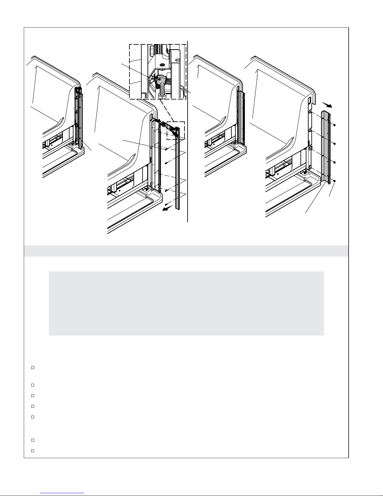
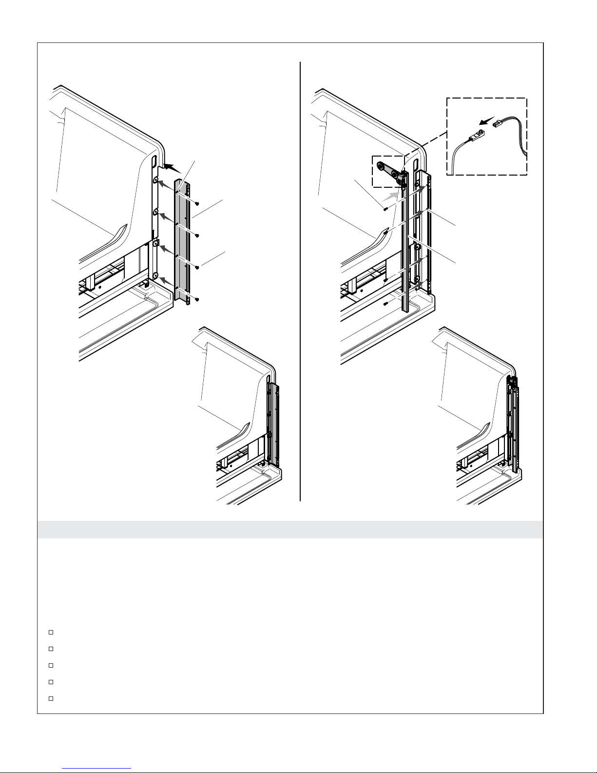
Remove Pulley Assemblies
Limit Switch
Red Screw
Pulley
Assembly
Remove Mounting Brackets
Connector
Blue
Screw
Mounting
Brackets
6. Remove the Pulley Assemblies and Mounting Brackets
Installations Requiring Disassembly Only
Disassembly Checkpoint #2
The steps below may not be necessary. Make sure removing the pulley assemblies,
mounting brackets, and/or receptor tray is required. The bath can usually be moved into
place after the door is removed.
If the bath can be moved into place without further disassembly, go directly to the
″Position the Bath″ section.
IMPORTANT! Save and organize all screws and hardware. All parts will be reused.
Remove the Pulley Assemblies
Pull the limit switch wires at the top of each pulley through the opening in the bath until the
connector appears, then disconnect them.
Remove the four red screws from the drain side of the bath. Take care not to strip the screw heads.
Remove the pulley assembly from the drain side of the bath.
Remove the four red screws from the other side of the bath. Take care not to strip the screw heads.
Remove the pulley assembly from the other side of the bath.
Remove the Mounting Bracket
Remove the four blue screws from the drain side of the bath. Take care not to strip the screw heads.
Remove the mounting bracket from the drain side of the bath.
1128532-2-G 14 Kohler Co.

Remove the Pulley Assemblies and Mounting Brackets (cont.)
Remove the four blue screws from the other side of the bath. Take care not to strip the screw heads.
Remove the mounting bracket from the other side of the bath.
Kohler Co. 15 1128532-2-G
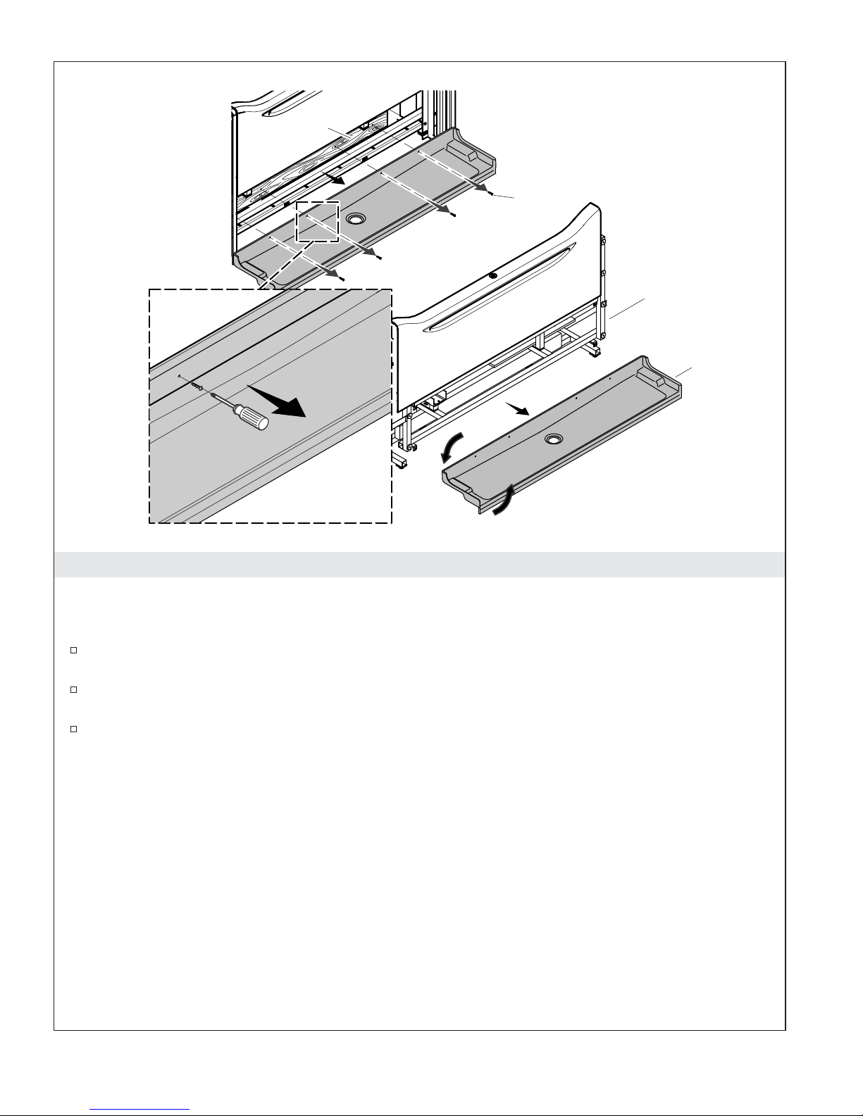
Board
Screw
Support
Frame
Receptor Tray
7. Remove the Receptor Tray
Installations Requiring Disassembly Only
NOTE: Take care not to scratch the receptor tray or strip the screw heads when performing these steps.
Remove each of the screws securing the receptor tray to the frame. Take care not to strip the screw
heads.
Carefully remove the receptor tray by rotating it down and out away from the counterweight
guides.
Set the receptor tray aside in a safe place.
1128532-2-G 16 Kohler Co.
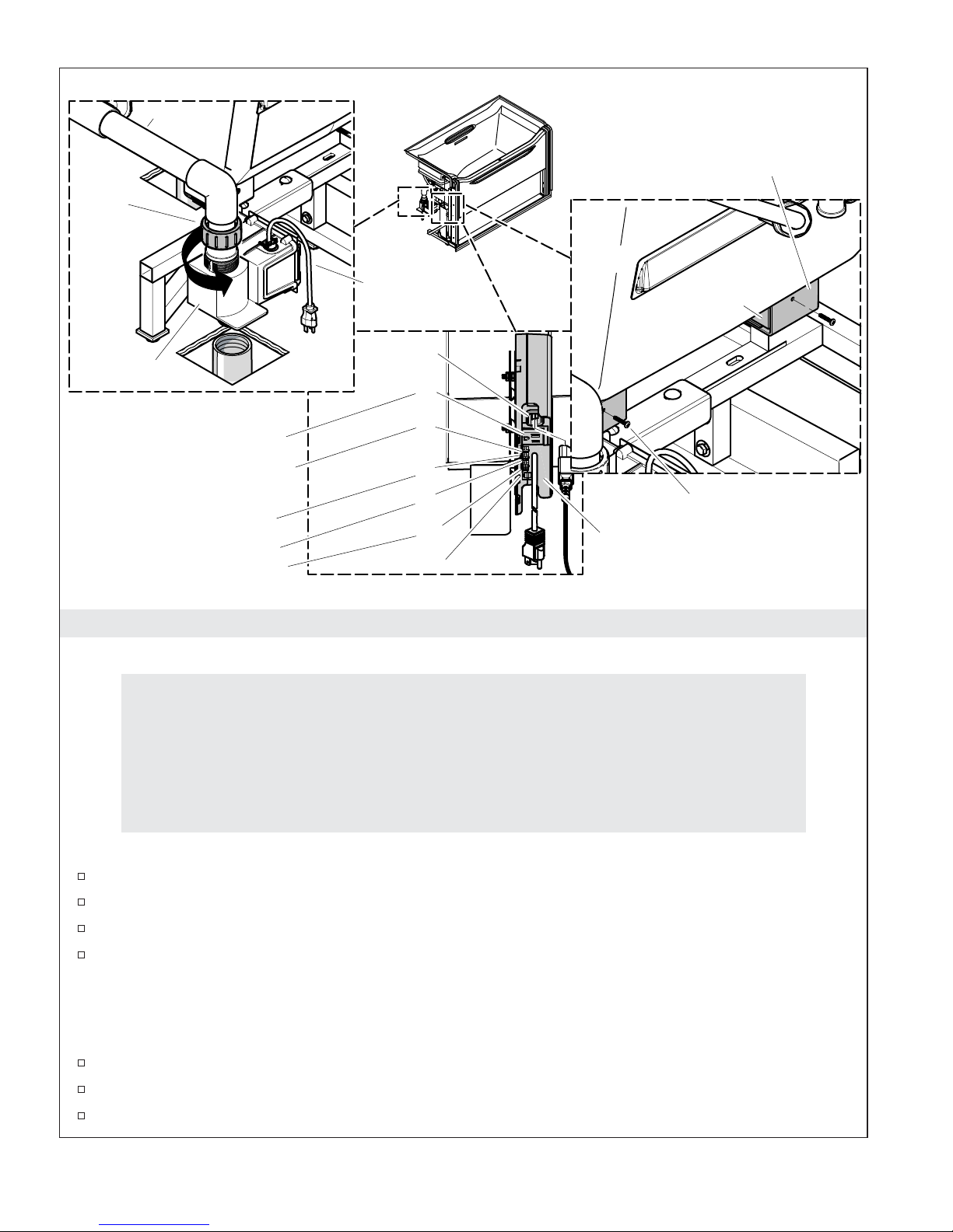
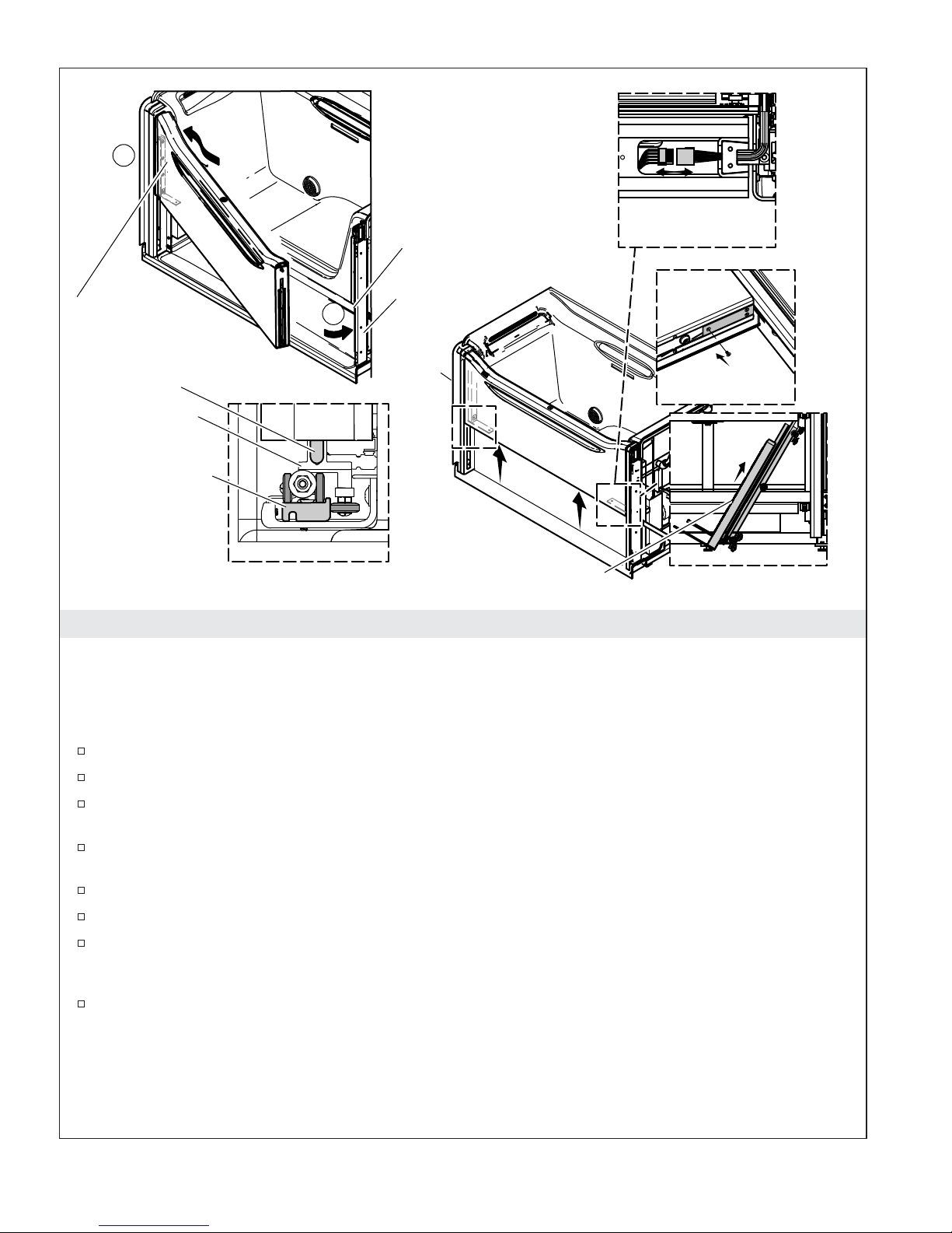
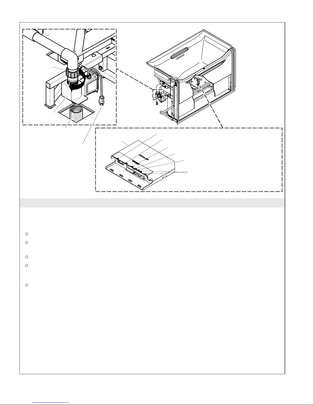
Nut
Water Inlet
Bracket
Power Cord
J1
Drain Valve
J2
J3
Disconnect drain valve power.
Disconnect level sensing wires.
Disconnect limit switch wires.
Open
Disconnect door power.
J4
J5
J6
and
J7
8. Disconnect the Components
Installations Requiring Disassembly Only
Disassembly Checkpoint #3
The steps below may not be necessary. It is only required for doorways less than 31″ (787
mm). Make sure removing the bath from the frame is required. The bath likely can be
moved into place while attached to the frame.
Wood Block
Remove all screws
from (4) brackets.
Controller
If the bath can be moved into place without further disassembly, go directly to the
″Position the Bath″ section.
IMPORTANT! Save and organize all screws and hardware. All parts will be reused.
Disconnect the water inlet from the drain valve by loosening the nut. Save the O-ring.
Disconnect the level sensing wires at the controller.
Disconnect the limit switch wires at the controller.
Disconnect the door power wire at the controller.
Disconnect the Bath from the Frame
IMPORTANT! Be careful not to strip or damage the screws when removing them. When the bath is
reattached they will be reused, as will the original holes in each of the wood blocks.
Disassemble the bath from the support frame at the four brackets by removing the two screws.
Carefully lift the bath clear of the frame and set it aside.
Temporarily secure any loose wires and protect them from being damaged.
Kohler Co. 17 1128532-2-G
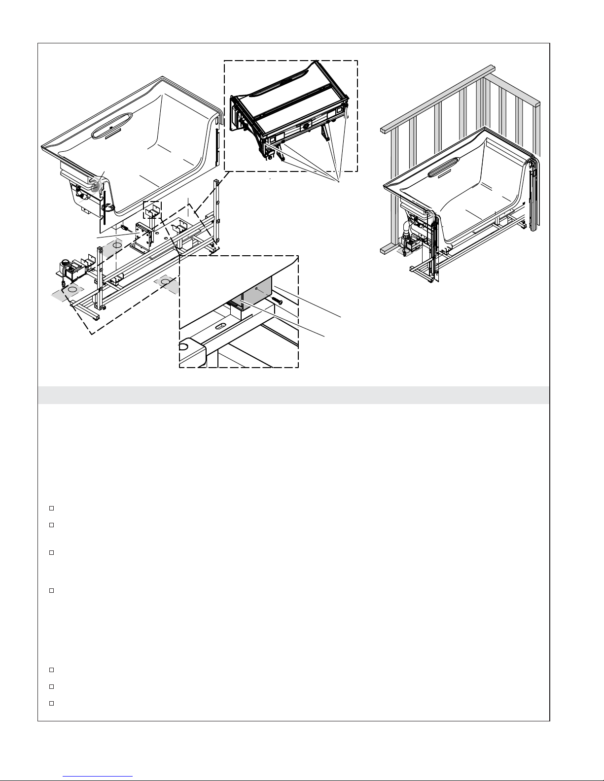
Attach the bath to the support frame.
Controller
Bottom View
Leveling Foot Locations (6)
Install the bath to the frame.
Bracket
Wood Block (4)
Align all of the holes.
9. Position the Bath
All Installations
IMPORTANT! If the installation site is in an area where frequent or prolonged power outages occur,
Kohler Co. recommends that a minimum 350 VA Uninterruptible Power Supply (UPS) be installed as a
backup power source for the bath controller.
IMPORTANT! If a handshower is being installed, follow the instructions packed with the handshower.
Make sure the handshower installation conforms to all applicable backflow prevention requirements.
Install any valving or accessories.
Adjust each of the six leveling feet until they extend 1/4″ (6 mm) to 1/2″ (13 mm) from the base of
the frame.
Install the grab bar and slotted overflow drain following their installation instructions. If the PVC
pipe included with the drain is too short, cut a new length using commonly available 1-1/2″
Schedule 40 PVC pipe.
If a UPS backup power supply is being installed to the controller, install it now following the UPS
manufacturer’s instructions. Do not connect the power source to the UPS at this time.
Reassemble the Bath (if disassembled)
NOTE: The following steps are not required if you did not disassemble the bath. If the bath has not been
disassembled, proceed to ″Move the Bath Into the Stud Pocket″ steps below.
Cover the area of the bathroom floor where the bath will be reassembled with protective material.
Move the bath and support frame from the staging area to the installation area.
If the bath was removed from the frame, carefully position and center the bath on the frame.
1128532-2-G 18 Kohler Co.

Position the Bath (cont.)
Make sure each of the wood support feet are positioned correctly in the corresponding bracket, with
the screw holes aligned.
Secure each of the wood blocks to the brackets using the original screws and holes.
Move the Bath Into the Stud Pocket
Install the outlet drain in the footwell to the bath following the instructions supplied with the drain.
Move the assembled bath into the final installation position in the stud pocket.
Kohler Co. 19 1128532-2-G
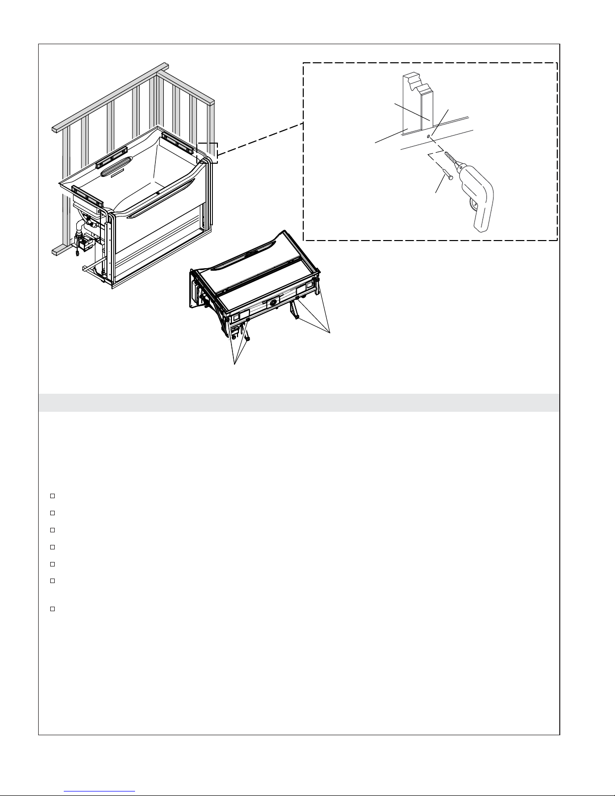
Nail furring strips
to the studs.
Stud
Use #6 large-head
galvanized nails to
secure the nailing-in
flange to the studs.
Drill a small hole
through the nailing-in
flange at each stud.
Bottom View
Leveling Foot Locations
Leveling Foot Locations
10. Level and Secure the Bath
All Installations
IMPORTANT! Do not anchor the bath to the stud pocket until instructed to do so.
IMPORTANT! Do not level the bath with the counterweights installed. The counterweights and door
assembly could cause the bath to shift, causing leveling to be incorrect.
Install metal shims under each of the leveling feet to protect the floor.
Check for level on the back edge and each side of the bath as shown.
Adjust the leveling feet as needed to level the bath.
Recheck for level.
Repeat until the bath is level.
Check each of the leveling feet and confirm they make firm contact with the metal shims and
subfloor.
Secure the bath to the studs with nails or screws, using the nailing-in flange.
1128532-2-G 20 Kohler Co.
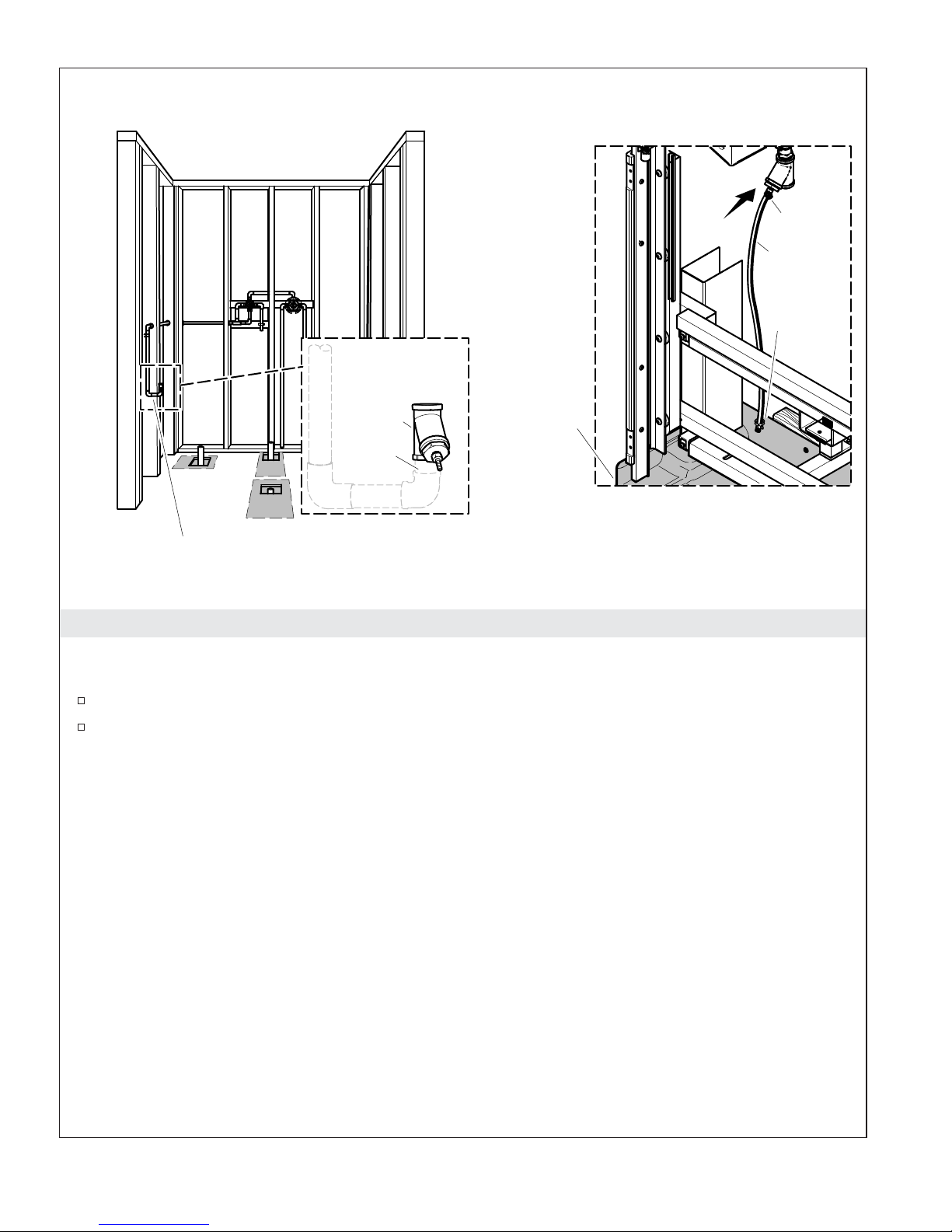
Accumulator
Fitting
(supplied)
3/4" NPT
Attach the water supply to accumulator.
Receptor Tray
11. Attach the Water Supply to the Accumulator
All Installations
Clamp
Drain Line
Cable
Tie
Attach the water supply line to the water accumulator at the inlet (3/4″ NPT).
Move the drain line out of the way if the receptor tray needs to be reinstalled.
Kohler Co. 21 1128532-2-G
Pulley
Assembly
Drain Line
Board
Accumulator
Drain Line
Clamp
Receptor Tray
Install, route and secure
accumulator drain line
to receptor tray.
Approximately
1/4" (6 mm)
clearance required
from receptor tray.
Cable
Tie
2-1/2" (64 mm) Minimum Air Gap
Strainer Body
Install drain and attach to receptor tray.
Water Inlet
Nut and O-Ring
Drain Valve
12. Install the Receptor Tray, and Connect the Drains
All Installations
Install the drain to the receptor tray following the drain manufacturer’s instructions.
When Reassembling the Receptor:
NOTE: These steps are not required if the receptor tray was not removed in a previous step. If the
receptor tray is already assembled, go to ″All Installations″ below.
Carefully move the receptor tray into position, rotating it up and in.
Make sure the subfloor cutout is large enough to prevent any contact with the backside of the receptor at
or near the drain.
Reconnect the receptor tray to the frame using the existing holes and the screws that were removed
previously.
1128532-2-G 22 Kohler Co.

Install the Receptor Tray, and Connect the Drains (cont.)
Dry fit the pulley assemblies and mounting brackets by aligning the holes.
IMPORTANT! Confirm the receptor tray and pulley assemblies do not contact each other. If the receptor
tray and pulley assembly come in contact with each other, remove the receptor tray, remove any
obstructions with the subfloor, and reposition the receptor tray as needed.
IMPORTANT! Cover the receptor tray with protective material to avoid damaging it.
All Installations
Connect each of the three drains to their corresponding drain outlet. Each requires a 1-1/2″ drain
line. The drain valve connection requires a 1-1/2″ NPS coupling (not provided).
Route the accumulator drain line loosely through the cable tie attached to the receptor tray. Locate
the outlet of the drain line directly over the drain, with a minimum 2-1/2″ (64 mm) air gap
(typically required by code) to protect against back siphoning.
IMPORTANT! Cover the receptor tray with protective material to avoid damaging it.
Kohler Co. 23 1128532-2-G
Install Mounting Brackets
Install Pulley Assemblies
Limit Switch Wires
Slot
Mounting
Bracket
Blue
Screw
Red
Screw
Slot
Pulley
Assembly
13. Install the Mounting Brackets and Pulley Assemblies
Installations Requiring Disassembly Only
NOTE: These steps are not required if the mounting brackets and pulley assemblies were not removed in
a previous step. If the mounting brackets and pulley assemblies were not removed, proceed to the ″Install
the Door ″ section.
Install the Mounting Brackets
Align a mounting bracket with the holes in the bath.
Use the four previously removed blue screws to secure the mounting bracket to the bath.
Adjust the mounting bracket so it is centered in the slots or out as far as the slots allow.
Tighten the screws.
Repeat with the second mounting bracket.
1128532-2-G 24 Kohler Co.

Install the Mounting Brackets and Pulley Assemblies (cont.)
Install the Pulley Assemblies
NOTE: Make sure each pulley assembly is located on the side it was originally installed on.
Position a pulley assembly onto the mounting bracket.
Align the mounting holes in the center of the slot.
Secure the pulley assembly to the mounting bracket with the previously removed red screws.
Repeat with the second pulley assembly.
Reconnect the limit switch wires, making sure they do not interfere with the pulleys or cables as
they move.
Kohler Co. 25 1128532-2-G
1
Swing other end of door
in place and latch.
Align rollers on drain
side and swing door
2
Mounting Bracket
in on an angle.
Latch Pin
Strike Plate
Track for
Pulley Assembly
Top View
Proper Roller Alignment
Drain End
14. Install the Door
Installations Requiring Reassembly Only
Lubricate if necessary.
Reconnect door
power cord.
Bottom View
Attach screws.
Install roller assembly.
NOTE: These steps are not required if the door was not removed in a previous step. If the door was not
removed, proceed to the ″Attach the Counterweights″ section.
Align the door and rollers on the drain side of the bath.
Pivot the other side of the door inward until the latch pins engage on both sides of the door.
Have the second installer hold the door up and brace it with a 2x4 under the door, with the bottom
end of the 2x4 positioned on the subfloor (not the receptor tray).
Slide the roller assembly up and partially into the door from below, making sure to feed the door
power cord back into the door.
If the bracket was removed, reattach it to the roller assembly.
Reconnect the power cord to the door, then slide the roller assembly all the way up into the door.
If it is difficult to move the roller assembly into place, apply a small amount of lubricant to the faces
of the roller assembly. If necessary loosen the blue mounting bracket screws on one or both sides.
Retighten the blue screws when the roller assembly is in place.
Reinstall the cover plate on the base of the door and secure with the screw(s) previously removed.
1128532-2-G 26 Kohler Co.
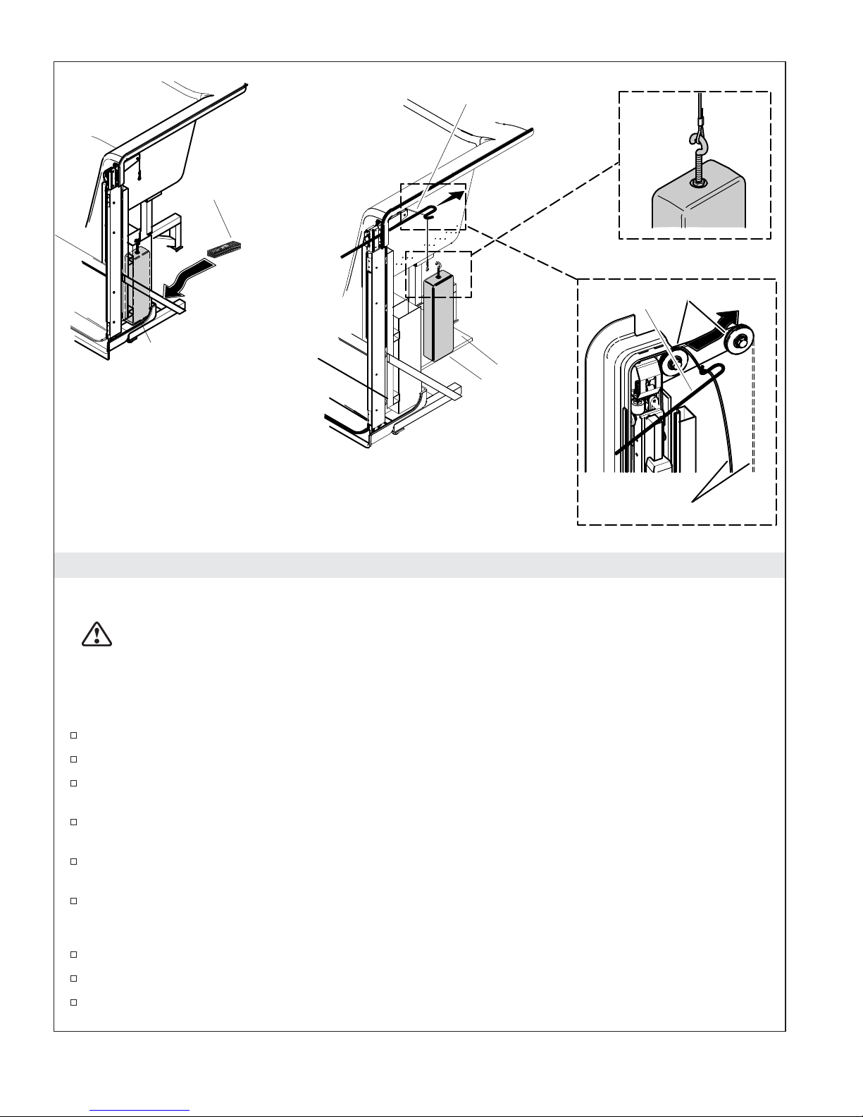
Shims
Tool (Optional)
Counterweight
guides are located here.
Add shims that are 1/2"
(13 mm) to 1" (25 mm)
(total height).
Position the counterweight
on the shims.
15. Attach the Counterweights
All Installations
CAUTION: Risk of crushing or pinching. Take care when installing the pulley cable. If access is
limited, use the tool supplied with the literature. Keep your fingers away from the pulleys while
installing the cable if the tool is not used.
Board
Counterweight
Route the cable over
the pulleys.
Attach the counterweight
Pulley
Tool
Cable
.
IMPORTANT! The door must be in the raised position while these steps are performed. Support the door
with a 2x4 or have the second installer hold it in place until the counterweights are attached.
Position extra protective material on the receptor tray under the counterweight guides.
Position 1/2″ (13 mm) to 1″ (25 mm) high shims under each of the counterweight guides.
On the drain side of the bath, carefully position a counterweight on shims aligned with the
counterweight guide.
On the side of the bath opposite the drain, carefully position the counterweight on the shims or the
board, aligned with the counterweight guide.
On each side, carefully run the pulley cable directly to the counterweights, making sure it does not
interfere with the limit switch wires and door power cable.
Attach the cables to the counterweights.
NOTE: If access to the side of the bath is limited, use the supplied tool to install the pulley cables.
Position each pulley cable over both pulleys.
On the drain side of the bath, remove the support shims and carefully lower the counterweights.
On the side of the bath opposite the drain, remove the support shims and carefully lower the
counterweights.
Kohler Co. 27 1128532-2-G

Attach the Counterweights (cont.)
Check to make sure the counterweights are freely suspended and do not come in contact with the
receptor tray.
Raise and lower the door several times.
If the counterweights contact the receptor tray, make sure the cable is positioned over both pulleys.
IMPORTANT! The receptor tray and counterweights should not come in contact with one another. If they
are in contact, first make sure the cable is positioned on both pulleys. Then check if the cutout is too small
and the receptor tray is making contact with the subfloor. Remove the receptor tray, remove any
obstructions with the subfloor, and reposition the receptor tray as needed.
Check Operation
Raise and lower the door several times.
Make sure the wires do not contact the pulley cables.
If the counterweights contact the receptor tray, make sure the cable is positioned over both pulleys.
Make sure the counterweights function smoothly. They should not make any contact with the bath.
If the counterweights make contact with the bath, check to make sure the bath is level. Adjust level
as needed.
1128532-2-G 28 Kohler Co.
Nut
and O-Ring
Drain Valve
Water Inlet
Attach the drain.
Controller
Connect to controller, J2.
J1 - Power Cord to Wall Outlet
J2 - Power Cord to Drain Valve
J3 - Connection for Level Sensing Probes
J4 - Connection for Limit Switch Wires
J5 - Open
(Alternate for Level Sensing Probes)
J6 / J7 Power Cord Connection to Door
16. Connect the Components
All Installations
NOTE: Depending upon disassembly, some or all of these components may still be connected.
Confirm the O-ring is in place and connect the water inlet to the drain valve by tightening the nut.
Connect the drain valve power at controller J2. Do not plug the drain valve power cord into a
receptacle other than J2.
Connect the level sensing wires at controller J3.
Connect the limit switches at controller J4.
NOTE: Port J5 should remain unused.
Connect the door power at controllers J6 and J7.
Kohler Co. 29 1128532-2-G
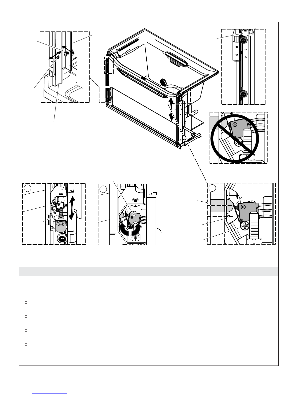
Blue
Screw
Red
Screw
Mounting Bracket
Bumper
Adjust roller
and mounting
bracket contact.
Pulley
Assembly
1
Tighten
nut.
Adjust the bumper pads.
Lift and lower door several
times with one finger to
establish smooth travel.
Limit Switch
2
Adjust the limit switches.
Latch Pin
(Centered)
Strike
Plate
Screw
Proper Bumper Adjustment
Improper Adjustment
(Blue Boot is not Visible)
3
Proper Adjustment
(Blue Boot is Visible)
Blue
Boot
17. Adjust the Bath Door
All Installations
Check and Adjust the Door Movement
Move the bath door up and down several times with one finger. Check for uneven movement,
rubbing, or shaking.
If the door shimmies or racks, adjust one or both of the mounting brackets inward using the blue
screws and slots, until they are snug against the rollers.
If the door shimmies more when it is fully lowered, adjust the bottom of each mounting bracket
inward using the top screw as a pivot point.
If the door shimmies more when it is fully raised, adjust the top of each mounting bracket inward
using the bottom screw as a pivot point.
NOTE: When properly adjusted the door should move up and down using one finger.
1128532-2-G 30 Kohler Co.
 Loading...