

Kohler K-1647, K-1698 Installation Manual
Installation Guide
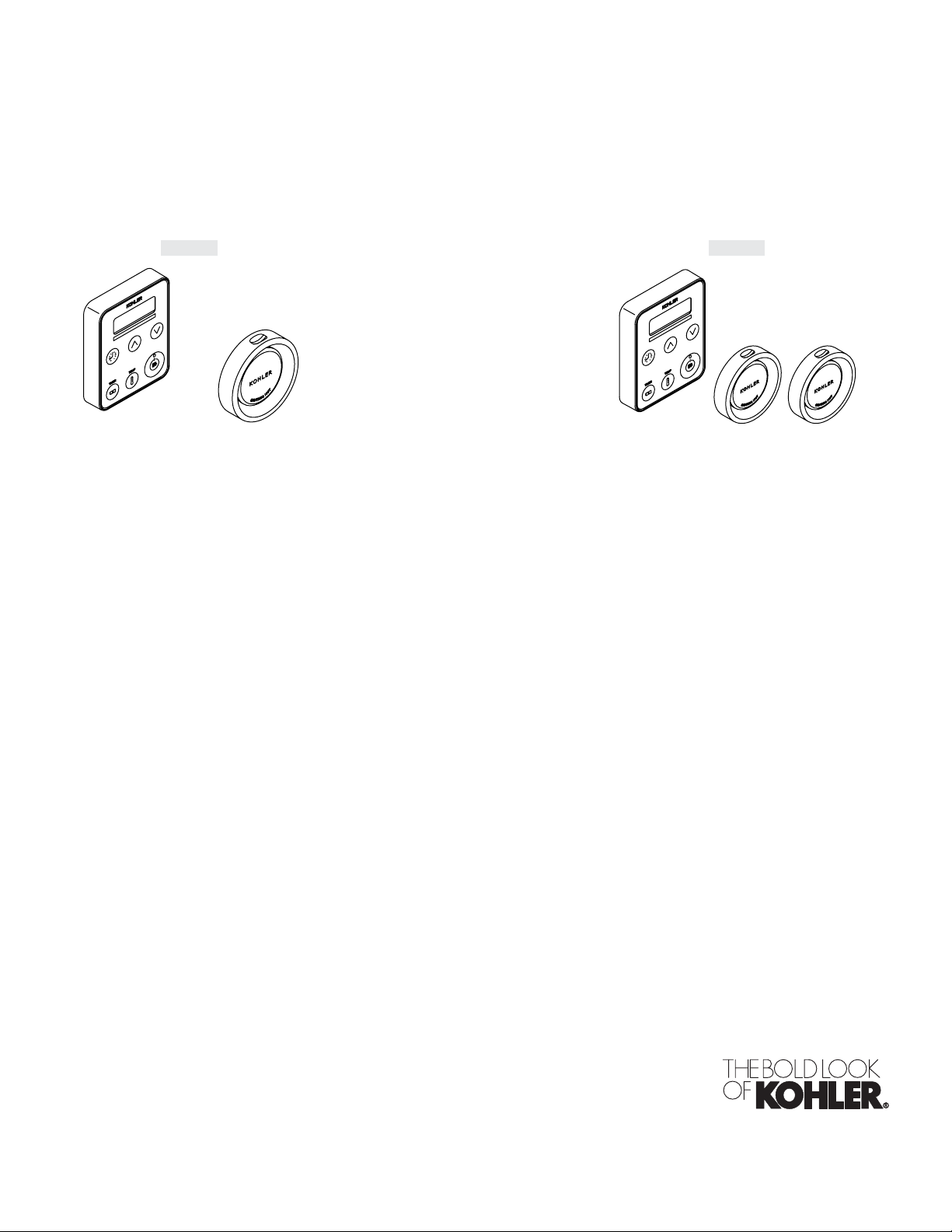
Steam Control Kit with Power Clean
K-1647 K-1698
M product numbers are for Mexico (i.e. K-12345M)
Los números de productos seguidos de M corresponden a México
(Ej. K-12345M)
Français, page “Français-1”
Español, página “Español-1”
1045320-2-E
Tools and Materials
Drill w/ 1-1/4" &
2-1/2" Hole Bit
Adjustable
Wrench
Screwdrivers
Sealant
Tape
Tape
Measure
Before You Begin
IMPORTANT! When using this unit, basic precautions should always be followed.
DANGER: Risk of electrocution. Disconnect the electricity to the working area at the main breaker
panel before performing these installation steps.
WARNING: Risk of personal injury. If you become uncomfortable while taking a steam bath, you
should power off the unit. Cool off with the shower, open the door, or exit the unit.
WARNING: Risk of allergic reaction. Before adding any oils, aromatic therapies, or skin care
products to the aromatherapy well, make sure they will not cause an allergic reaction to the user.
WARNING: Risk of personal injury. This steam bath may not be suitable for use if you are
pregnant, have a heart condition, have high blood pressure, have circulatory problems, are under
the influence of alcohol, are taking drugs or are under the care of a physician. A steam bath can put
undue stress on the body, as does any hot bath, shower, or sauna.
WARNING: Risk of personal injury. DO NOT consume alcoholic beverages or take
medications/drugs prior to or when using the steam bath. Alcohol and drugs affect mental
judgement and inhibit bodily functions such as heartbeat and respiration, resulting in potentially
dangerous effects.
Silicone Sealant
WARNING: Risk of injury to children. Do not allow children to use this unit unless they are
closely supervised at all times. The steam generator is not designed to be used by children.
WARNING: Risk of scalding. Do not block the steam head or locate it near a seat or bench, as the
steam head is hot during operation and may scald the user if touched.
WARNING: Risk of property damage. Allow a minimum of 12″ (30.5 cm) of air space around the
steam generator at all times. This provides an area for the heat generated by the unit to dissipate.
NOTICE: Use this unit only for its intended use as specified in this manual. DO NOT use attachments not
recommended by Kohler Co.
Follow all local plumbing and electrical codes. All electrical work should be done by a licensed
electrician.
Do not install a GFCI to this unit. This will prevent nuisance tripping.
Disconnect all power before making any electrical connections.
Kohler Co. reserves the right to make revisions in the design of products without notice, as specified
in the Price Book.
1045320-2-E 2 Kohler Co.
Control
Kit
12" (30.5 cm)
Control
Kit
21"
(53.3 cm)
21"
(53.3 cm)
Control
Kit
21" (53.3 cm)
Steam
Head
6"
(15.2 cm)
21" (53.3 cm)
4-1/2"
(11.4 cm)
60"
(152.4 cm)
Steam
Head
K-1569/K-1669
60"
(152.4 cm)
K-1683/K-1684 K-1681/K-1682
6" (15.2 cm)
Control
Kit
4-1/2"
(11.4 cm)
Drain End
Control
Kit
Steam
Head
11"
(27.9 cm)
60"
(152.4 cm)
6"
(15.2 cm)
K-1687
Steam
Head
Steam
Head
Drain End
Steam
Head
Control
Kit
4-1/2"
(11.4 cm)
60"
(152.4 cm)
Control
Kit
11"
(27.9 cm)
60"
(152.4 cm)
6"
(15.2 cm)
K-1688
21" (53.3 cm)
Steam
Head
6"
(15.2 cm)
21" (53.3 cm)
Steam
Head
4-1/2"
(11.4 cm)
60"
(152.4 cm)
K-9488/K-9496
Steam
Head
6"
(15.2 cm)
Steam
Head
6"
(15.2 cm)
4-1/2"
(11.4 cm)
60"
(152.4 cm)
K-9486/K-9489
Drain End
Steam
Head
Drain End
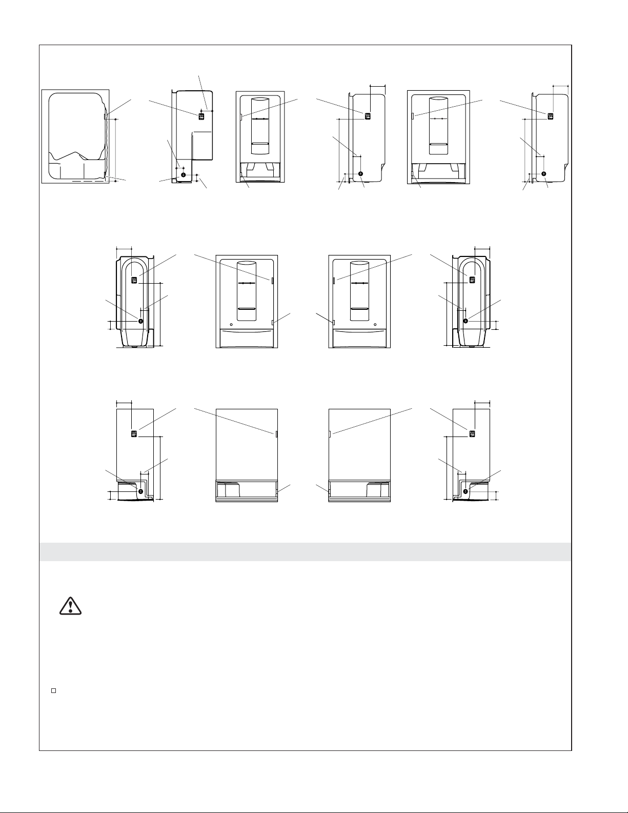
Steam Hardware Locations
Modules (Single Steam Head)
WARNING: Risk of scalding. Do not locate the steam head near a seat or bench, as the steam head
is hot during operation and may scald the user if touched.
NOTICE: It is recommended to locate the control kit and steam head on the same wall as the plumbing
controls. For optimum performance, do not locate the control kit directly above the steam head. Locate the
steam head 6″ (15.2 cm) above the floor and a minimum of 4-1/2″ (11.4 cm) from the threshold. The steam
head should always be located as far away from the seating area as possible.
Identify the model number of your shower module in the illustration. If necessary, consult the
Homeowners Guide included with your shower module to verify the model number. If the
dimensions for your particular model are not shown, refer to the ″Custom Shower Application″
illustration in the ″Prepare the Site″ section.
Kohler Co. 3 1045320-2-E

Steam Hardware Locations (cont.)
Determine the location of the control kit and steam head based on the roughing-in dimensions
illustrated. Dimensions given in the rough-in information are crucial for proper installation.
Locate the control kit and steam head in the location indicated. All measurements are from the
inside of the module.
1045320-2-E 4 Kohler Co.
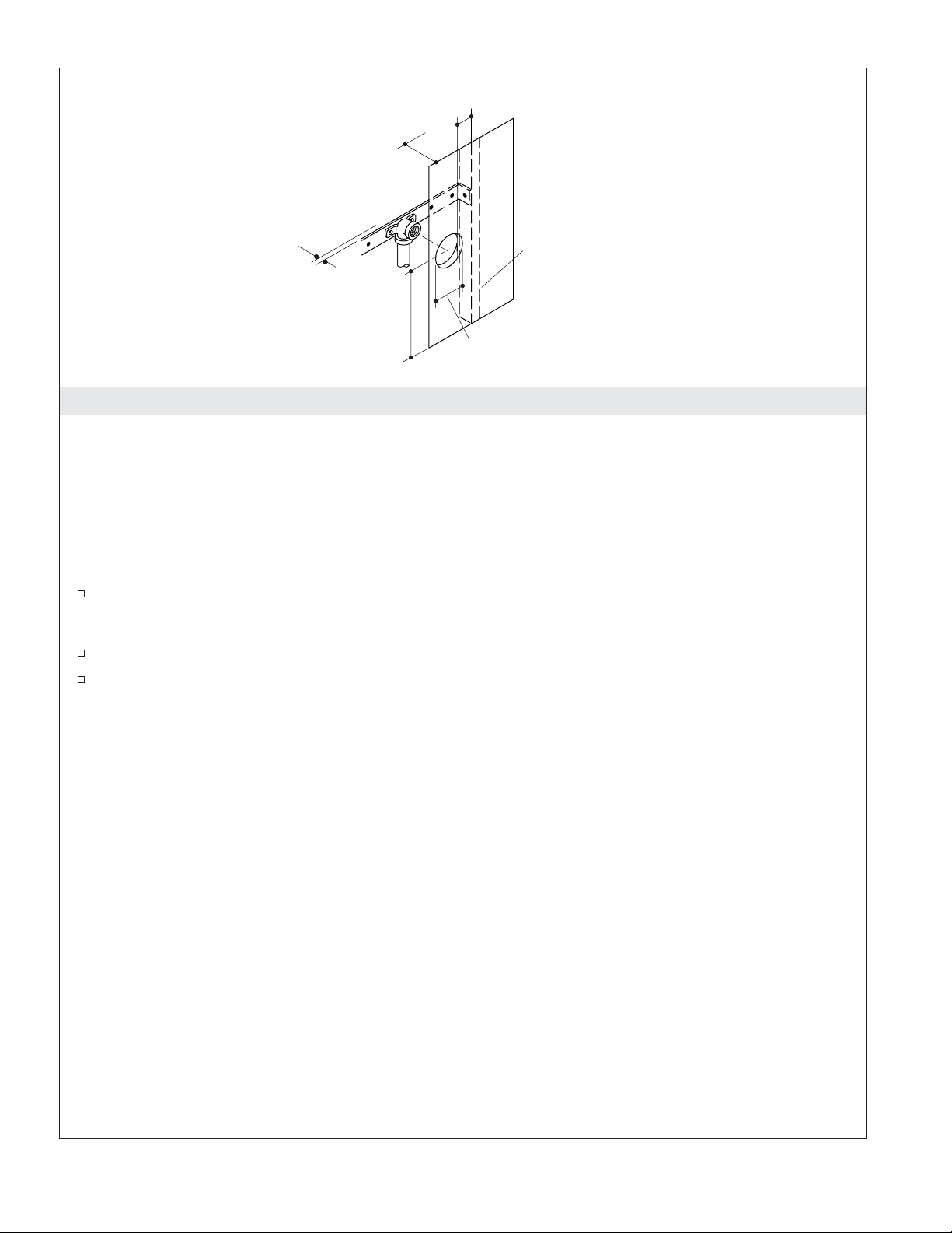
1" (2.5 cm) Min
4-1/2" (11.4 cm)
Min
Provide clearance
from wall.
6" (15.2 cm) from Floor
2-1/2" (6.4 cm)
Wall Stud
Custom Shower
Applications
1. Prepare the Site
Single Steam Head Installations
NOTICE: The steam head must be installed at least 6″ (15.2 cm) from the floor in an area where contact
with occupants is unlikely.
NOTICE: Provide clearance between the back wall and the elbow. The elbow should not contact the back
wall.
NOTE: The edge of the hole should be at least 1″ (2.5 cm) away from all wall studs.
Drill a 2-1/2″ (6.4 cm) diameter hole in the wall at the desired steam head location.
NOTE: For all the connections, use thread sealant tape and do not overtighten the fittings.
Install a 1/2″ NPT connection on the end of the steam housing assembly.
Secure the connection to the framing whenever possible.
NOTE: The steam generator(s) will not operate without water and a connected user interface control.
Kohler Co. 5 1045320-2-E
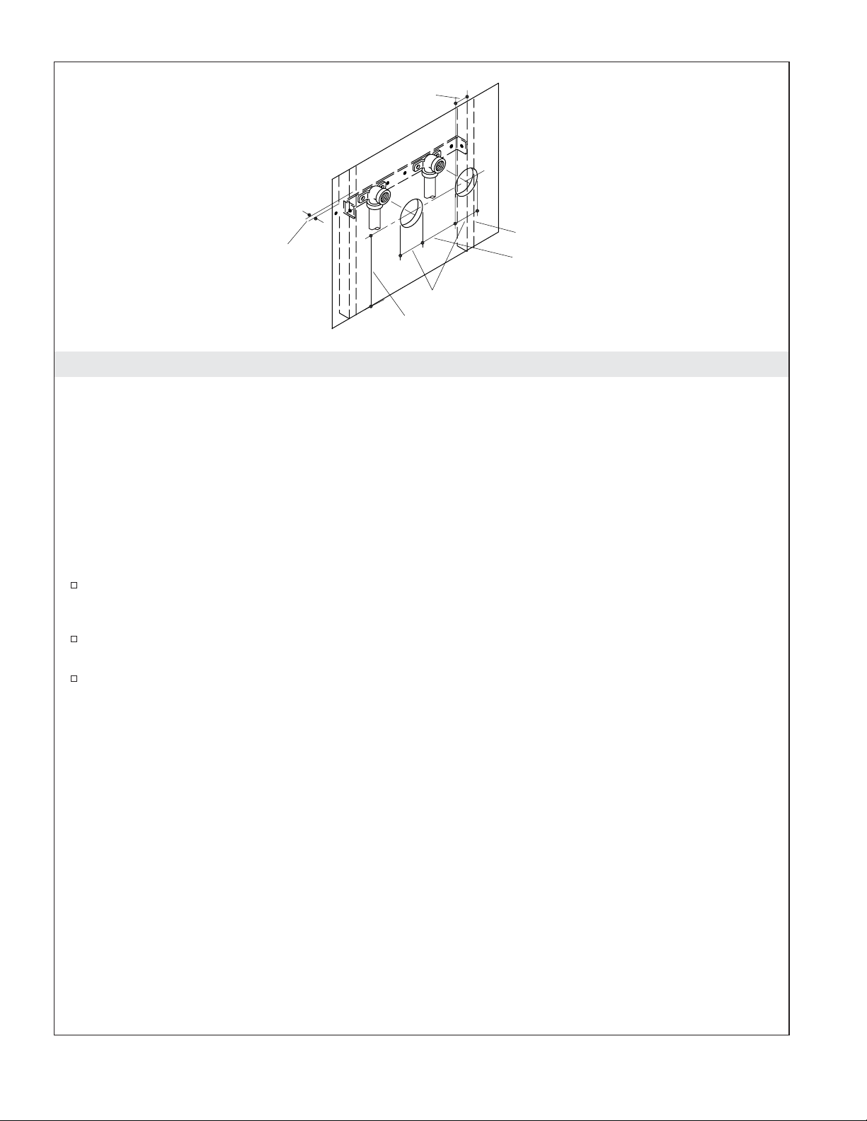
1" (2.5 cm) Min
Wall Stud
Provide clearance
from wall.
2-1/2" (6.4 cm)
6" (15.2 cm) from Floor
10"
(25.4 cm) Min
2. Prepare the Site
Dual Steam Head Installations
NOTICE: Each steam head must be installed 6″ (15.2 cm) from the floor in the shower room.
NOTICE: Provide clearance between the back wall and the elbows. The elbows should not contact the
back wall.
NOTE: The diagram shows two steam heads installed in the same stud pocket. They may also be installed
in separate stud pockets.
NOTE: The edge of the hole should be at least 1″ (2.5 cm) away from all wall studs with 10″ (25.4 cm)
minimum separating the steam heads.
Drill a 2-1/2″ (6.4 cm) diameter hole in the wall at the desired steam head location.
NOTE: Use thread sealant tape on all connections. Do not overtighten the fittings.
Install a 1/2″ NPT elbow in each desired location. Leave clearance between the inside wall and the
back of the elbow to allow heat and condensation to dissipate.
Secure the elbow to the framing whenever possible.
NOTE: The steam generator(s) will not operate without water and a connected user interface control.
1045320-2-E 6 Kohler Co.
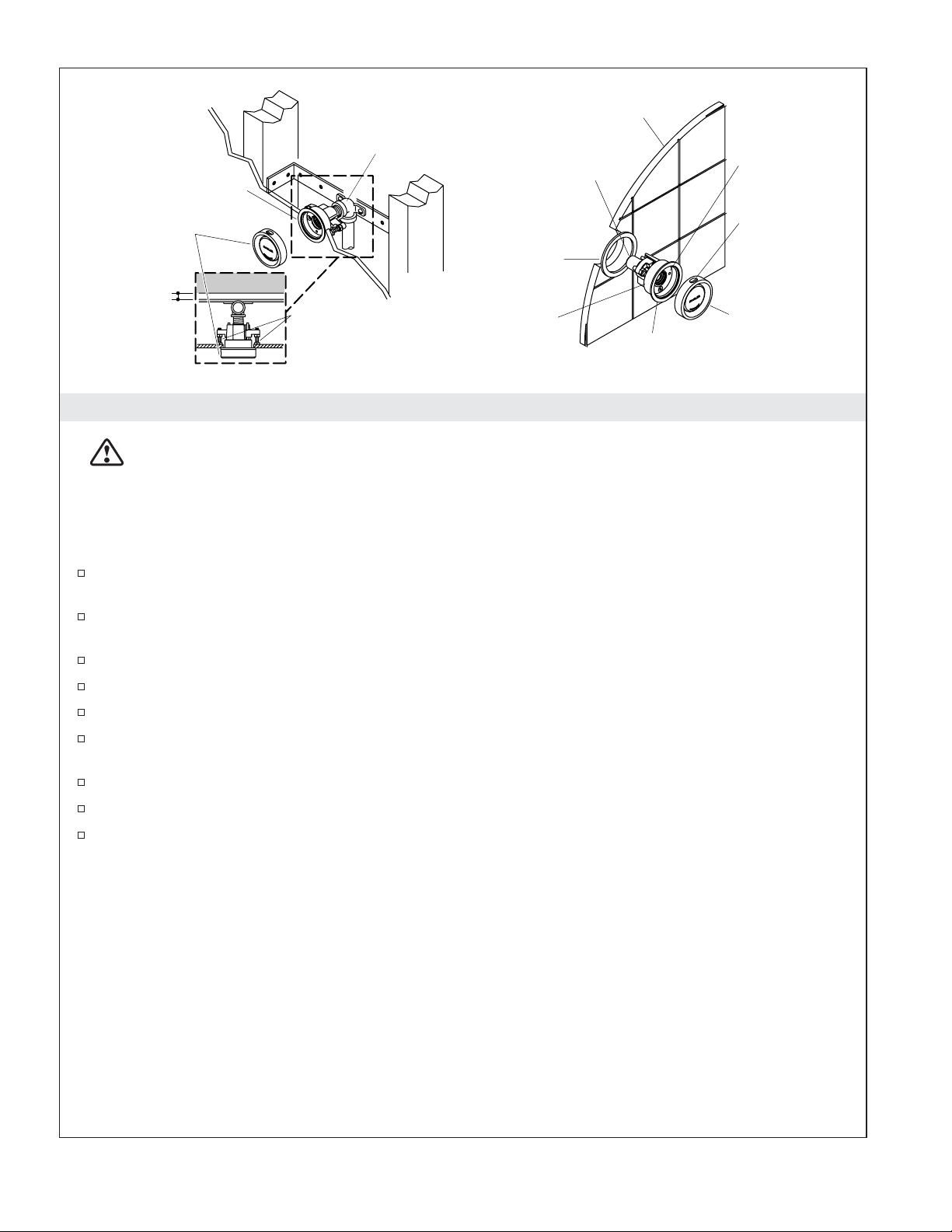
Wall
1/2" NPT Elbow
Nipple
Steam Housing
Steam Head
Gasket
Hold-Down
Screw
Aromatherapy
Well
Provide
clearance
from wall.
Adjustment Screws
Steam
Housing
Steam Head
Lip
3. Install the Steam Head(s)
WARNING: Risk of scalding. Do not locate the steam head near a seat or bench, as the steam head
is hot during operation and may scald the user if touched.
NOTICE: Do not obstruct the steam head with shut-off valves, plugs, or caps.
NOTE: The steam housing can be adjusted for a wall thickness of 3/16″ (5 mm) to 1-1/2″ (3.8 cm) using
the adjustment screws located on the steam head housing.
Position the gasket (provided) around the base of the steam housing so the gasket is between the
wall and the lip of the steam housing.
Turn the adjustment screws on the steam housing until the distance between the back edge of the
steam housing and the head of each adjustment screw is equal to the wall thickness.
Tighten the adjustment screws securely. Do not overtighten.
Secure the steam housing to the wall by carefully tightening the hold-down screws.
Thread the steam head clockwise onto the steam housing assembly until it is hand-tight.
Turn the steam head counterclockwise until the aromatherapy well is located at the 12 o’clock
position.
Apply thread sealant tape to the 1/2″ NPT male threads on the steam housing.
Push the steam housing assembly through the installation hole from inside the shower.
Complete the connection of the steam line to the steam housing.
Kohler Co. 7 1045320-2-E
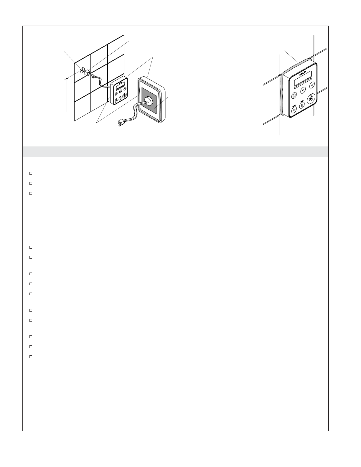
1-1/4" (3.2 cm) D.
Control Connector
Apply silicone sealant.
Control Pad
60" (152.4 cm)
to Floor
Remove adhesive backing.
Apply silicone sealant.
Back View
4. Install the Steam Control
NOTICE: Do not locate the control kit directly above the steam outlet.
Make sure that the power is turned off at the main breaker panel before proceeding.
Locate the control pad on the wall 60″ (152.4 cm) up from the floor.
At the selected location, drill a hole 1-1/4″ (3.2 cm) in diameter.
NOTICE: Do not pinch, nail, wedge, or use undue force when handling the control connector and the
control pad wire. Any damage may result in control kit failure. If the control pad is not installed
immediately, protect the control connector with tape or other shielding material.
NOTICE: When installing the control kit, allow room in the control cable for a drip loop. The drip loop
will discourage moisture from following the control cable to the steam generator.
Pull the control connector from the steam generator through the drilled hole.
Carefully plug the control connector to the control pad wire using the double-end female connector
(provided).
Restore the power at the main breaker panel.
Turn on both water and power to the generator.
Test the control pad to ensure it is functioning properly. Refer to the ″Using the Control Pad″
section.
Remove the adhesive backing from the back of the control pad.
Apply a continuous bead of silicone sealant around the back edge of the control pad and around the
perimeter of the adhesive area.
Press the control pad firmly onto the wall.
Apply a bead of silicone sealant around the outside edge of the control pad.
Allow the silicone sealant to cure for 24 hours before use.
1045320-2-E 8 Kohler Co.

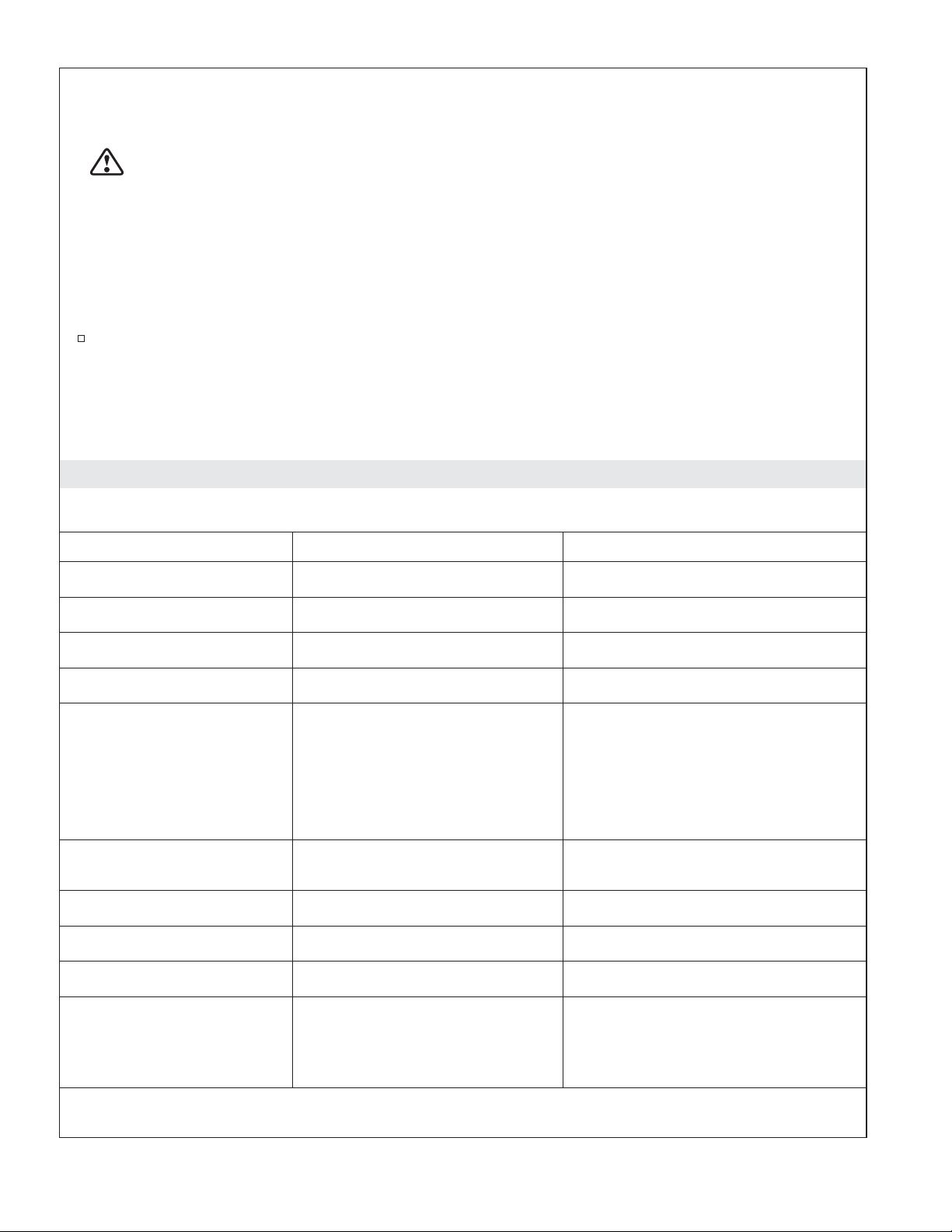
Window
Increase
Clock
Timer
Decrease
On/Off
Temperature
5. Operate the Steam Control
Steam Control Operation
NOTE: The clock is always displayed in the LED window when the steam is not in use.
Push the ″On/Off″ button to start the steam.
When the button is pushed the green LED light on the ″On/Off″ button turns on and remains on
until the unit is turned off. The LED window reads ″On″ for the first three minutes of operation if
the factory settings are not changed.
The current temperature is then displayed until the target temperature is reached.
Push the ″On/Off″ button again to stop the steam. The green LED ″On/Off″ button turns off and
the LED window reads ″Off″ for 5 seconds, then returns to the time of day.
NOTE: When turning the unit on, the steam duration and temperature settings will be based upon the
previous user settings. The settings of a new control unit are 113°F (45°C) for 15 minutes.
Steam Control Adjustment
Make sure the steam control unit is turned ON before making any of the following adjustments.
Press the ON button to activate the steam control unit.
Push the ″On/Off″ button to start the steam. The control window will display ″On″ for three
minutes. If nothing else is adjusted, the clock time will then be displayed.
Push the temperature icon and the LED flashes the previous setting.
To adjust the setting press the up arrow to increase the temperature and the down arrow to decrease
the temperature. The maximum allowed temperature is 125°F (52°C). The minimum operating
temperature is 90°F (32°C).
After 5 seconds, the flashing stops and ambient temperature is displayed as it changes to the target
temperature.
Push the timer icon and the LED flashes the previous setting. Press the up or down icons to adjust
the setting up or down. After 5 seconds the flashing stops and the timer setting is displayed. If the
up or down icons are not pushed the time will continue to count down. The minimum operating
time is 10 minutes, the maximum operating time is 20 minutes.
Push the clock icon and the LED flashes the current time of day setting. Press the up or down icons
to adjust the clock. After 5 seconds, the flashing stops and the set time is displayed.
Press the ″On/Off″ button to stop the steam and exit at any time. The control window will display
″Off″ for five seconds and default to the clock time.
To toggle the temperature reading between Fahrenheit and Celsius, push and hold the temperature
icon in 3 seconds.
Kohler Co. 9 1045320-2-E
Operate the Steam Control (cont.)
The Power Clean Function
WARNING: Risk of personal injury. Stay out of the showering area when the power clean function
is activated.
NOTICE: Users will be automatically reminded to use power clean after 600 minutes of steam generator
use. The LED window will display ″run″″PCLn″. The steam generator may be run three times before the
power clean function must be run.
NOTE: When the power clean function is activated, water will typically discharge from the steam head.
NOTE: The power clean cycle must be completed before normal steam operation may be resumed.
To activate the power clean function: Push the timer icon, up arrow, and down arrow at the same
time for five seconds. The LED window will display ″PCLn,″″On,″ then count down the cycle time
until the power clean function is complete. The power clean function runs for approximately 45
minutes and shuts off automatically when complete.
NOTE: If electrical power to the steam generator is interrupted during the power clean function, the cycle
must be restarted when the electrical power is restored.
Troubleshooting Guide
The troubleshooting guide is for general aid only. For service and installation issues and concerns, call
1-800-4-KOHLER.
Symptoms Probable Causes Recommended Action
1. ″Err 1″ appears on the
control pad.
2. ″Err 2″ appears on the
control pad.
3. ″Err 3″ appears on the
control pad.
4. ″Err 4″ appears on the
control pad.
5. ″Err 5″ appears on the
control pad.
6. ″Err 6″ appears on the
control pad.
7. ″Err 7″ appears on the
control pad.
8. ″Err 8
9. Unit shuts off. A. Unit has been in operation for
10. No steam is being
″ appears on the
control pad.
generated.
A. The power button is stuck. A. Reset the power at the breaker.
A. ″Up button″ is stuck. A. Reset the power at the breaker.
A. ″Down button″ is stuck. A. Reset the power at the breaker.
A. ″Time″ button is stuck. A. Reset the power at the breaker.
A. The float switch was tripped for
10 seconds. The generator is not
getting enough water.
B. Water feed assembly is blocked. B. Remove and inspect the water feed
C. Water supply to generator is
shut off.
A. The maximum heat has been
exceeded.
A. ″Temperature″ button is stuck. A. Reset the power at the breaker.
A. ″Clock″ button is stuck. A. Reset the power at the breaker.
more than 20 minutes.
A. Piping not properly attached. A. Reattach the pipes properly.
B. Steam head blocked. B. Remove the steam head (after
A. Check the water supply for proper
flow and check that the water
supply to generator is turned on.
assembly in the generator.
C. Check for a clogged water line and
check that the water supply to
generator is turned on.
A. Shut off the system and allow it to
cool. Reset the power at the
breaker.
A. Turn unit back on.
cooling) and check that the plunger
slides freely in the cap.
1045320-2-E 10 Kohler Co.
Troubleshooting Guide (cont.)
Symptoms Probable Causes Recommended Action
11. There is a continuous
flow of water from the
steam head. Water flow
during automatic purge
cycle is normal.
A. Water supply is incorrectly
attached to steam generator.
B. Water feed assembly is stuck. B. Remove and inspect the water feed
A. Connect the water supply to the
proper inlet.
assembly in the generator.
Kohler Co. 11 1045320-2-E
 Loading...