

Kodak Ngenuity 9150, Ngenuity 9090DC, Kodak Ngenuity 9125, Ngenuity 9000 Series, Ngenuity 9090DB User Manual
...Page 1

Page 2

Safety
User Precautions
• Place the scanner on a sturdy, level work surface capable of supporting 50.8 kg (112 lbs) and leave adequate clearance on
all sides of the scanner.
• When relocating the scanner, it is recommended that two people lift the scanner and use safe lifting techniques.
• Do not install the scanner in a location subject to dust, humidity or steam. This may cause electrical shock or a fire. Only use
the scanner indoors in a dry location.
• Make sure the electrical power outlet is located within 1.52 meters (5 feet) of the scanner and is easily accessible.
• When disconnecting equipment from the electric socket, be sure to grasp the plug, not the cord.
• Be sure the power cord is securely plugged into the wall outlet. Failure to do so may cause electrical shock or fire.
• Do not damage, knot, cut or modify the power cord or use a damaged power cord. This may cause electrical shock or fire.
• The scanner requires a dedicated and properly grounded power outlet. Do not use an extension cord or power strip with the
scanner.
• Do not leave the power cord plugged into the AC outlet if the scanner is not used for an extended period of time.
• Leave sufficient space around the power outlet so it can be easily unplugged in case of an emergency.
• Do not use the scanner if it becomes inordinately hot, has a strange odor, emits smoke, or makes unfamiliar noises.
Immediately stop the scanner and disconnect the power cord from the power outlet. Contact Kodak Service.
• Do not disassemble, service or modify the scanner except as explained in the User’s Guide.
• Do not move the scanner with the power cord and interface cable attached. This may cause damage to the cord/cable.
Remove the power cord from the wall outlet before moving or relocating the scanner.
• Follow the Kodak recommended cleaning procedures. Do not use air, liquid or gas spray cleaners. These cleaners displace
dust, dirt and debris to other locations within the scanner, which may cause the scanner to malfunction.
• Material Safety Data Sheets (MSDS) for chemical products are available on the Kodak website at: www .kodak.com/go/msds.
When accessing the MSDSs from the website, you will be required to provide the catalog number or keyword of the
consumable you want the Material Safety Data Sheet for. See the section entitled, “Supplies and consumables” later in this
guide for supplies and catalog numbers.
Users and their employers need to observe the common sense precautions applicable to the operation of any machinery. These
include, but are not limited to, the following:
• Do not wear loose clothing, unbuttoned sleeves, neckties, etc.
• Do not wear loose jewelry, bracelets, bulky rings, long necklaces, etc.
• Hair length should be kept short, using a hair net if needed, or tying long hair up in a bundle.
• Remove all other loose objects from the area that could be drawn into the machine.
• Take sufficient breaks to maintain mental alertness.
• Use only the recommended cleaning supplies.
• Do not use canned/compressed air.
Supervisors should review their employee practices and make compliance with these precautions a part of the job description
for operation of the scanner or any mechanical device.
Page 3

Environmental information
•The Kodak Ngenutiy Scanners are designed to meet worldwide environmental requirements.
• Guidelines are available for the disposal of consumable items that are replaced during maintenance or service; follow local
regulations or contact Kodak locally for more information.
• The product packaging is recyclable.
• Kodak Ngenutiy Scanners are Energy Star compliant and shipped from the factory with the default time set to 15 minutes.
European Union
This symbol indicates that when the last user wishes to discard this product, it must be sent to appropriate
facilities for recovery and recycling. Please contact your local Kodak representative or refer to www.kodak.com/
go/recycle for additional information on the collection and recovery programs available for this product.
Please consult www.kodak.com/go/REACH for information about the presence of substances included on the candidate list
according to article 59(1) of Regulation (EC) No. 1907/2006 (REACH).
Acoustic emission
Maschinenlärminformationsverordnung – 3, GSGV
Der arbeitsplatzbezogene Emissionswert beträgt <70 dB(A).
[Machine Noise Information Ordinance — 3, GSGV
The operator-position noise emission value is <70 dB(A).]
EMC statements
United States
This equipment has been tested and found to comply with the limits for a Class A digital device pursuant to Part 15 of the FCC
rules. These limits are designed to provide reasonable protection against harmful interference when the equipment is operated
in a commercial environment. This equipment generates, uses, and can radiate radio frequently energy and, if not installed and
used in accordance with the instruction manual, may cause harmful interference to radio communications. Operation of this
equipment in a residential area is likely to cause harmful interference in which case the user will be required to correct the
interference at their own expense.
Japan
This is a Class A product based on the standard of the Voluntary Control Council for interference by information Technology
Equipment (VCCI). If this equipment is used in a domestic environment, radio disturbance may arise. When such trouble
occurs, the user may be required to take corrective action.
Taiwan
WARNING: This is a Class A product. In a domestic environment this product may cause radio interference in which case the
user may be required to take adequate measures.
Page 4

Peoples Republic of China
WARNING: This is a Class A product. In a domestic environment this product may cause radio interference in which case the
user may be required to take adequate measures.
Korea
Please note that this equipment has obtained EMC registration for commercial use. In the event that it has been mistakenly sold
or purchased, please exchange it for equipment certified for home use.
European Union
WARNING: This is a Class A product. In a domestic environment this product may cause radio interference in which case the
user may be required to take adequate measures.
Page 5

OVERVIEW 1-1
INSTALLATION 2-1
GETTING STARTED 3-1
CONTROL PANEL AND NGENUITY OPERATOR UTILITY 4-1
ADVANCED FEATURES 5-1
MAINTENANCE 6-1
TROUBLESHOOTING 7-1
APPENDICES A-E
Page 6

1 Overview
Contents Supporting documentation..............................................................1-1
Optional accessories.......................................................................1-2
What’s in the box ...........................................................................1-2
Scanner components......................................................................1-3
Front view...................................................................................1-3
Rear view....................................................................................1-7
Kodak Ngenuity 9000 Series
Scanners offer optimal image quality
and scans a wider range of
documents than any other scanner in
its class. With an easy-to-use
operator interface and smart front
panel functionality, Ngenuity
Scanners are user-friendly and ideal
for companies in industries such as
health care, financial services,
insurance, government, transportation and service bureaus.
Supporting
documentation
These models are available:
• Kodak Ngenuity 9090DC Scanner — duplex scanner that scans 90
pages per minute in color, grayscale or black and white in landscape
mode.
• Kodak Ngenuity 9090DB Scanner — duplex scanner that scans 90
pages per minute in black and white or grayscale in landscape mode.
• Kodak Ngenuity 9125DC Scanner — duplex scanner that scans 125
pages per minute in color, grayscale or black and white in landscape
mode.
• Kodak Ngenuity 9150DC Scanner — duplex scanner that scans 150
pages per minute in color, grayscale or black and white in landscape
mode.
This User’s Guide provides information and procedures for using and
maintaining the Kodak Ngenuity 9000 Series Scanners. The
information in this guide is for use with all models unless otherwise
noted.
The following documentation is available in support of the Kodak
Ngenuity 9000 Series Scanners:
• User’s Guide
• Installation Guide
• Maintenance Reference Guide
A-61662 October 2011 1-1
Page 7

Optional accessories Front/Rear Printer Kit — front page (pre-scan) and back page (post-
scan) imprinting prints user-specified alphanumeric strings on the
documents as they are scanned. The printer kit includes one printer
accessory that can be installed in either the front or rear print position.
CAT No. 863 4230
Straight Pass-Through Adapter — this adapter allo ws you to connect
the exit tray to the straight pass-through door for better p aper handling.
CAT No. 802 9654
What’s in the box • Kodak Ngenuity 9090DC, 9090DB, 9125DC or 9150DC Scanner
• Power cord bundle
• USB cable
• Camera calibration kit
• Cleaning supplies
• Two Exit Deflectors (one Standard and one Lightweight)
• Installation CD which includes:
-VRS Software
- VRS User Manual and Release notes
- Ngenuity Operator Utility (NOU)
- ISIS/TWAIN Drivers
-User’s Guide
- Installation Guide
- Maintenance Reference Guide
1-2 A-61662 October 201 1
Page 8
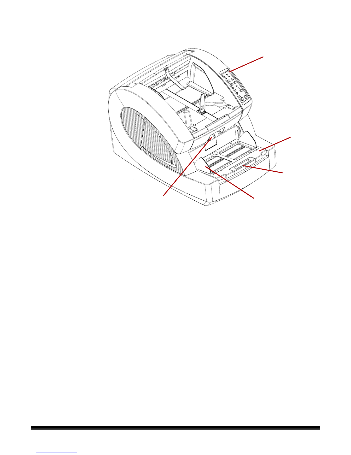
Scanner components
1
2
3
4
5
Front view
1 Control Panel — allows you to initiate scanner functions directly
from the scanner.
2 Feeder table — place the document s to be scanned on the feeder
table. It can be raised and lowered using the feeder table buttons
on the control panel.
3 Feeder table extender — provides a support for longer
documents that extend beyond the standard length. The extender
can be pulled out to add approximately 7 inches (18 cm) to the
feeder table.
4 Side guides — used to guide document(s) into the scanner’s
transport. They can be width-adjusted independently, which allows
for left-, right-, or center-feeding of documents.
5 Feed rollers — contains two rollers that assist in grabbing and
feeding documents into the scanner transport. These rollers can be
placed in an up position for manual feeding or a down position for
automatic document feeding.
A-61662 October 2011 1-3
Page 9
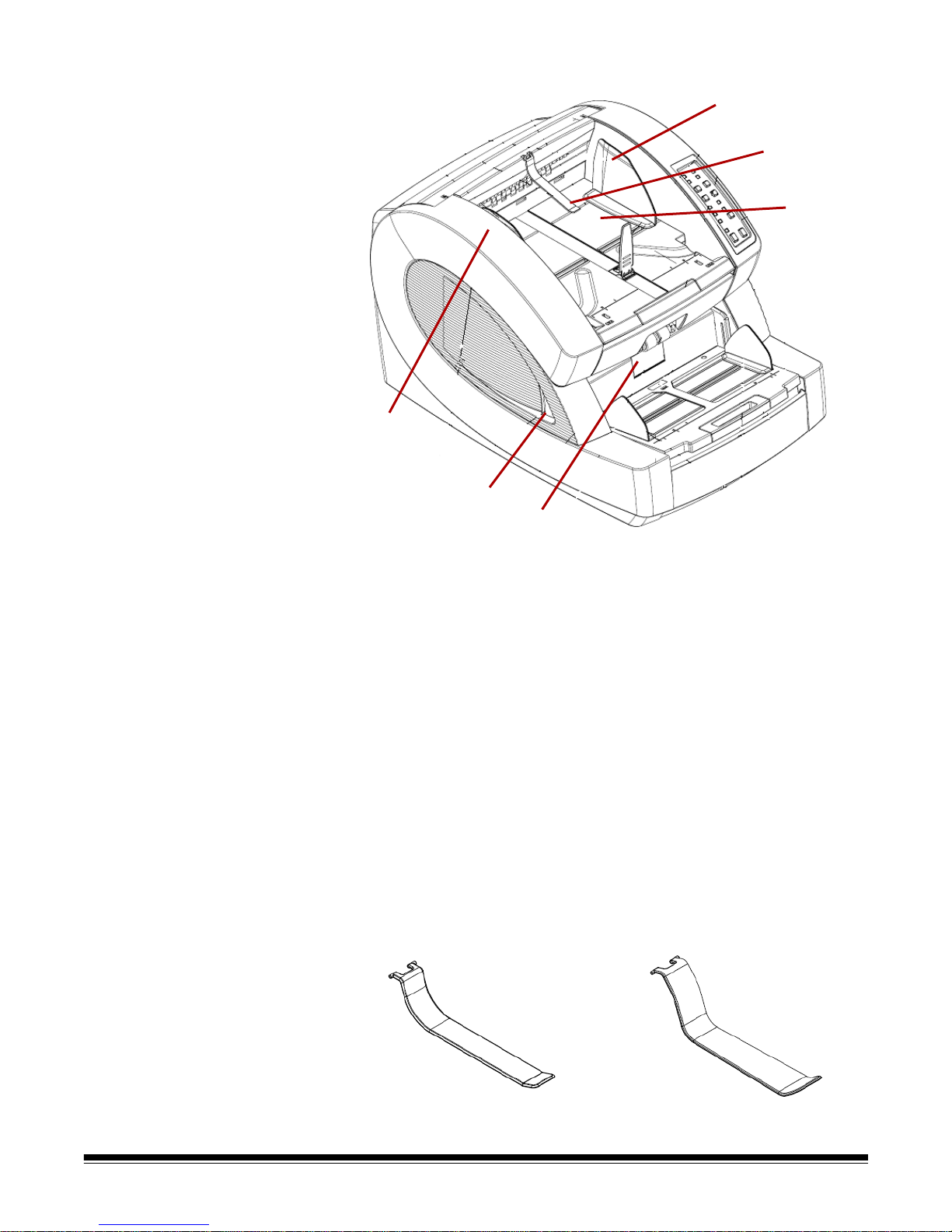
6 Separator roller door — allows access to the separator roller . The
6
7
8
9
10
11
separator roller assists in separating documents as they feed into
the transport.
7 Scanner cover release lever — there is a transport cover release
lever on each side of the scanner. Pull one or both levers towards
you to release and open the transport cover.
8 Scanner cover — opens in an upward position and will stay open
in a full-up position with the support of two gas springs.
9 Document output guides — used to guide the scanned
document(s) into a neat stack on the exit tray. They can be widthadjusted independently for left-, right- or center-document
alignment.
1-4 A-61662 October 201 1
10 Exit deflector — assists in the placement of document s in th e exit
tray. The scanner is packed with 2 exit deflectors. The standard
deflector should be used for most of your scanning needs. Use the
deeper deflector when scanning light-weight documents (i.e., rice
paper.)
Standard Exit Deflector Lightweight Exit Deflector
Page 10
11 Exit tray — where document(s) are deposited after they have
Tabs
Back of exit tray
Top/Front view of scanner - exit tray removed
Top row
Bottom row
Slots-
(slide into
slots)
Stops for bracing
kickstand wire
passed through the transport. There are two sets of slots that are
used for exit tray positioning depending on the types of document s
being scanned.
These positions are available:
- Flat: exit tray rests on top of the scanner in a flat, horizontal
position, with the tabs on the back of the tray hinged into the
bottom row of slots.
- Tilted Forward: tabs at the back of the exit tray are in the top
slots causing the exit tray to tilt in a downward position. This
position aids stacking of long documents in the exit tray.
- Tilted Backward: tabs at the back of the tray are in the bottom
row of slots. Pull the kickstand wire on the bottom of the exit tray
down and out. Snap the kickstand wire in the slots of the
scanner cover. This is useful when scanning small documents.
NOTES:
• If you have the optional imprinter, there is a door underneath the exit
tray that allows access to the front page imprinter.
• If you are using the optional straight pass-through adapter, you can
remove the exit tray from its position and place it in the back of the
scanner for straight pass-through output. For information on inst alling
and using the straight pass-through adapter, see Appendix C,
Installing and Using the Straight Pass-Through Adapter.
A-61662 October 2011 1-5
Page 11

12 Document stop guide — adjust this guide to match the length of
12
13
the documents being scanned, which aids in neat document
stacking. Slide the document stop guide toward you to lengthen the
distance or slide it away from you to shorten the distance.
The document stop guide should be folded down when scanning
extra long documents that require the use of the exit tray extender.
NOTE:Positioning the document stop guide too close to the back of
the exit tray (towards the back of the scanner) can cause
documents to jam as they exit the scanner.
13 Exit tray extender — pull the extender out when scanning longer
documents.
A second document stop guide is located on the end of the exit tray
extender when scanning extra long documents. When not in use,
fold the extender down.
1-6 A-61662 October 201 1
Page 12

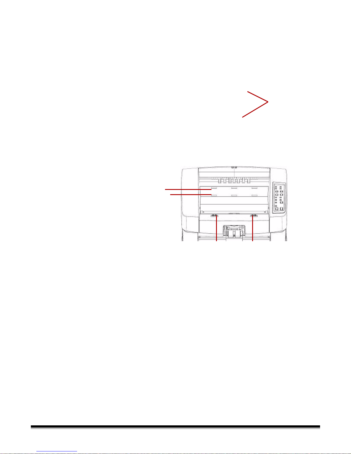
Rear view
1
2
3
4
5
6
7
8
9
1 Imprinter door — provides access to the optional imprinter for
installation and maintenance.
2 Straight pass-through door — allows you to use the optional
straight pass-through adapter. When the door is open and the exit
tray is attached, documents are fed through this exit. This is useful
for scanning thick or stiff documents. Only open this door when you
are using the straight pass-through feature, if the door is opened
while scanning in rotary mode, a document jam will occur.
NOTE: When the straight pass-through door is open, the Back Door
status light on the control panel will be lit.
3 SCSI connector — connects an optional SCSI cable (cable and
SCSI card are not provided).
4 USB connector — connects the USB cable to the scanner and
host PC.
5 Fan — for cooling the scanner. The fan is part of the scanner’s
power supply. Make sure to properly vent the scanner for optimal
performance.
6 Power connector — connects the power supply to the scanner.
7 Power switch — turns the scanner on (I) and off (O).
8 Foot — four rubber feet allow for clearance below the scanner.
9 Intake vent (on side) — used for drawing air in for cooling. Be sure
to position the scanner in such a way that the intake vent is not
blocked.
NOTE: Be sure to maintain an additional 4-5 inches (10-13 cm) of
additional clearance at the front, back and sides of the scanner
for proper ventilation.
A-61662 October 2011 1-7
Page 13

2 Installation
Contents Installing the exit deflector ..............................................................2-1
Installation: with a USB connection ................................................2-2
Installation: with an optional SCSI connection................................2-3
This section provides detailed information supporting the Installation
Guide that is provided with your scanner. Follow these steps in the
order they are provided to install your scanner.
NOTES:
• If you have already performed all of the steps in the Installation
Guide, skip this section.
• When positioning the scanner, be sure to provide adequate
clearance at the back of the scanner if you will be using the rear
document exit. For more information on the rear document exit, see
Appendix C, Installing and Using the Straight Pass-Through Adapter.
• The scanner weighs approximately 112 pounds (50.8 kg). Be sure to
incorporate the appropriate manpower before moving or lifting the
scanner.
Installing the exit
deflector
• Verify th at your host PC meets the system requirements as specified
in Appendix A, Specifications.
• The scanner is packed with a set of language-specific Control Panel
overlays. The English overlay is installed on the scanner . If you prefer
a different language, take the desired overlay and adhere it to the
control panel.
The scanner is packed with two exit deflectors. The exit deflector aids
in better document stacking. The standard exit deflector sh ould be used
for most of your scanning needs. The lightweight exit deflector should
be used when scanning light-weight documents.
• Install the exit deflector by clipping it to the rail at the top of the
scanner.
A-61662 October 2011 2-1
Page 14

Installation: with a
USB connection
If you are using the optional SCSI connection, refer to the next
section for installation instructions.
1. Without the scanner attached, turn on the host PC.
2. Load the Installation CD into the CD-ROM drive and install the
software in the following order: Ngenuity VRS software first, then the
Ngenuity Operator Utility (NOU). You do not need to reboot the host
PC after installing each software application.
NOTE: For the latest drivers, go to www.Kodak.com/go/scanners.
3. Power down the host PC.
4. Attach the host PC to the scanner using the supplied USB cable.
5. Turn on the scanner. After the initialization sequence has finished,
turn on the host PC.
NOTE: If you are prompted to check for VRS updates, select No.
6. Complete the “Found New Hardware” wizard (twice) to install the
USB drivers.
7. Launch the Ngenuity Operator Utility (NOU) by double-clicking the
NOU icon found on the desktop of the host PC.
8. Confirm the Ngenuity Operator Utility is communicating with the
scanner and all the self tests have passed.
The installation is complete. You are now ready to scan. Refer to the
instructions for your scanning application or document management
software.
2-2 A-61662 October 201 1
Page 15

Installation: with an
optional SCSI
connection
The Kodak Ngenuity Scanner is equipped to accommodate a SCSI
connection for communication between the scanner and host PC. The
optional SCSI connection can be used in lieu of the standard USB
connection.
To use a SCSI connection, a SCSI card and cable is required. Kodak
does not provide a SCSI card or cable with the Ngenuity Scanner;
therefore, these items must be purchased separately. A SCSI
connection kit is not available through Kodak; however, Kodak has
certified that Adaptec’s 29160 LP or regular profile card is compatible
with Ngenuity Scanners. The SCSI cable must be a D68-pin SCSI-3
cable.
1. Without the scanner attached, turn on the host PC.
2. Load the Installation CD into the CD-ROM drive and install the
software in the following order: Ngenuity VRS software first, then
the Ngenuity Operator Utility (NOU). You do not need to reboot the
host PC after installing each software application.
NOTE: For the latest drivers, go to www.Kodak.com/go/scanners.
3. Power down the host PC and remove the power cord.
4. Install the SCSI card (Adaptec 29160) in the host PC. See the
instructions that are included with the SCSI card.
5. Connect the host PC to the scanner.
6. Connect the power to the scanner and reconnect power to the host
PC.
7. Turn the scanner on and wait for the initialization sequence to
complete.
8. Turn on the host PC.
9. Follow the prompts within the New Hardware Found wizard.
10.Launch the Ngenuity Operator Utility (NOU) by double-clicking the
NOU icon found on the desktop of the host PC.
A-61662 October 2011 2-3
Page 16

The Ngenuity Operator Utility Home Screen (default) will update when
the scanner self tests have passed and communication with the
scanner has been established.
NOTE: If the Ngenuity Operator Utility failed to connect with the
scanner, refer to Chapter 7, Troubleshooting for more
information.
2-4 A-61662 October 201 1
Page 17

3 Getting Started
Contents Getting your scanner ready to scan................................................3-1
Making scanner adjustments..........................................................3-1
Getting your documents ready to scan...........................................3-2
Manually feeding documents..........................................................3-3
Accelerated scanning (VRS only)...................................................3-4
Getting your scanner
ready to scan
Making scanner
adjustments
1. Press the power switch on the back of the scanner to On (I). The
control panel indicators will blink a test sequence and the power
mode indicator will flash until scanner initialization is complete.
2. After the power mode indicator on the control panel is a steady
green, turn on your PC (for SCSI connection only).
NOTE: For more information regarding the control panel, the Ngenuity
Operator Control and various scanning modes, see Chapter 4.
Before scanning documents, you may need to adjust your side guides,
feeder table extender and exit deflector to accommodate the size of the
documents you are scanning.
• The side guides on the feeder table can be moved in and out to
accommodate the size of the documents you are scanning.
• If you are scanning documents longer than 11 inches (279.4 mm),
pull the feeder table extender out. The feeder table extender will
support documents up to 15 inches (381 mm) long.
• To handle longer paper in the exit tray, pull out the exit tray extender.
Adjust the position of the exit tray extender so that it will
accommodate the length of the documents. The exit tray extender is
adjustable to 17 inches (432 mm). When scanning a document
longer than 17 inches (432 mm) or A3 size (420 mm), fold down the
exit tray extender so that the longer paper will fit in the exit tray.
A-61662 October 2011 3-1
• If you are feeding thick documents you can use the optional straight
pass-through adapter to aid in more efficient document feeding and
stacking. See Appendix C, Installing and Using the Straight Pass-
Through Adapter for more information.
Page 18

Getting your
For best scanning results, follow these guidelines:
documents ready to
scan
• Standard paper size documents feed easily through the scanner.
When organizing your documents for scanning, stack the document s
so the lead edges are aligned and centered in the feeder table. This
allows the feeder to introduce documents into the scanner one at a
time.
Maximum thickness:
Rotary: .0015 - .035 in. (.038 mm - 0.89 mm)
Straight Pass-Through Door: .0015 - .070 in. (.038 mm - 1.78 mm)
2
Maximum weight: 7 to 320 lbs. (30 to 1,200 g/m
• Remove all staples and paper clips before scanning. St aples and
paper clips on documents may damage the scanner and documents.
• Glued or curled documents may cause a p aper jam or damage in the
feeder.
• All inks and correction fluids on the paper must be dry before
scanning is started.
• Sheets that are exceptionally thick or thin should be placed in the
feeder table manually, one sheet at a time, or you can use the
optional straight pass-through adapter.
The following types of documents may cause jams or may cause the
scanner to feed more than one sheet at a time.
) bond
- Overhead projector sheets, plastic films, cloth or metallic sheets
- Paper with irregularities such as tabs, staples, paste and similar
items
- Thick or irregular documents such as envelopes or documents that
are glued together
- Thermal or heat sensitive paper
- Tracing paper
- Damaged or wrinkled documents
- Photographs
- Coated paper
- Thick plastic cards such as credit cards or identification cards
- Torn sheets and documents with notches, holes, punched or
perforated sheets
- Extremely smooth or shiny paper
- Paper that is highly textured
- Paper with carbon sheets
- Carbonless (NCR) paper
3-2 A-61662 October 201 1
Page 19
Manually feeding
documents
For demonstration purposes, VRS Test Application is used in the
following procedure.
1. Turn on the scanner and wait until the scanner is ready.
2. Turn on the host PC.
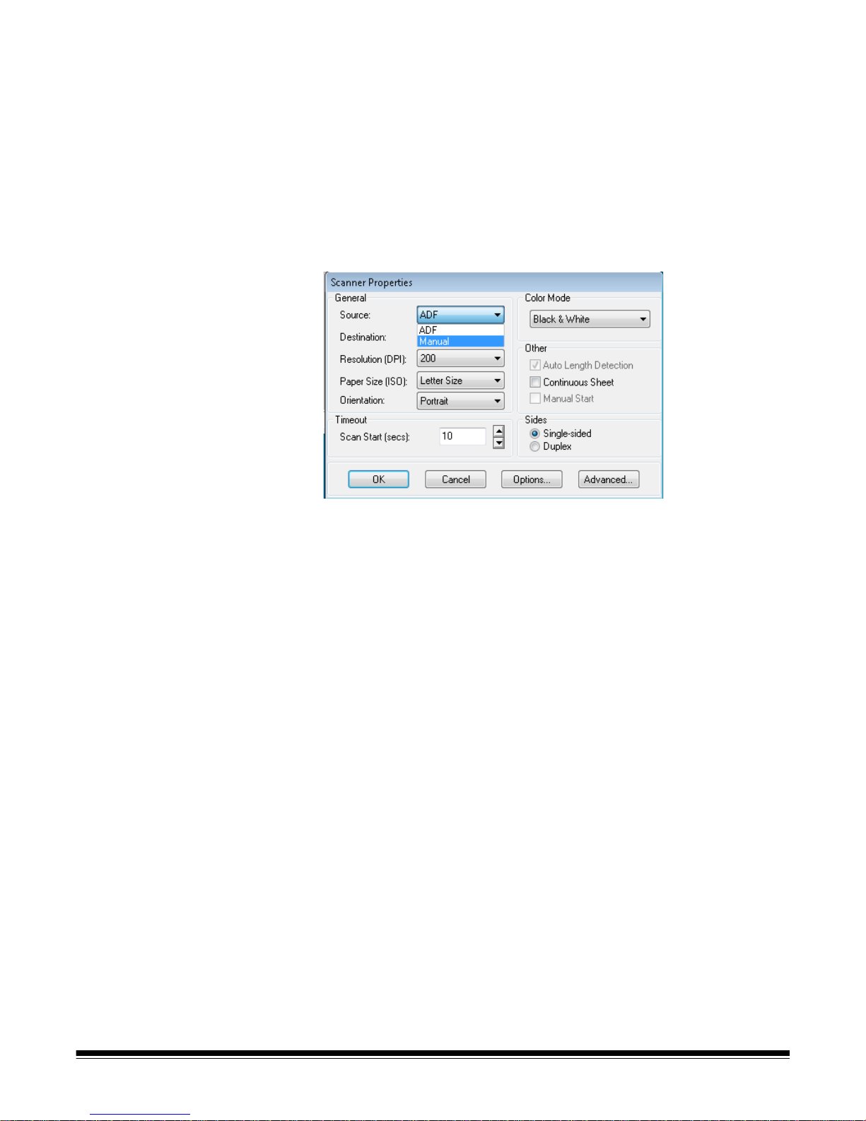
3. Launch the scanning application (in this example, VRS Test
Application) and from the Menu bar, select Source>Scanner
(Source = 9000 with VRS with AIPE).
4. When the scanner is connected, select Source>Properties to open
the scanning application’s Scanner Properties window.
5. Select Manual from the Source drop-down box.
6. Lift the skimmer to the up position.
7. Remove any paper from the feeder.
8. Start a scan, either single or batch. The feeder table will move up,
and the Manual Feed LED will light. The scanner motor will start and
beep indicating it is ready for scanning.
9. Carefully insert the page, keeping your hands and fingers away from
the rotating tires on the feed rollers. The scanner will feed the p age,
run it through the scanner and generate an image.
NOTE: If you selected batch scan, you can continue to insert
pages, one at a time.
10.When you are finished, press Stop.
A-61662 October 2011 3-3
Page 20
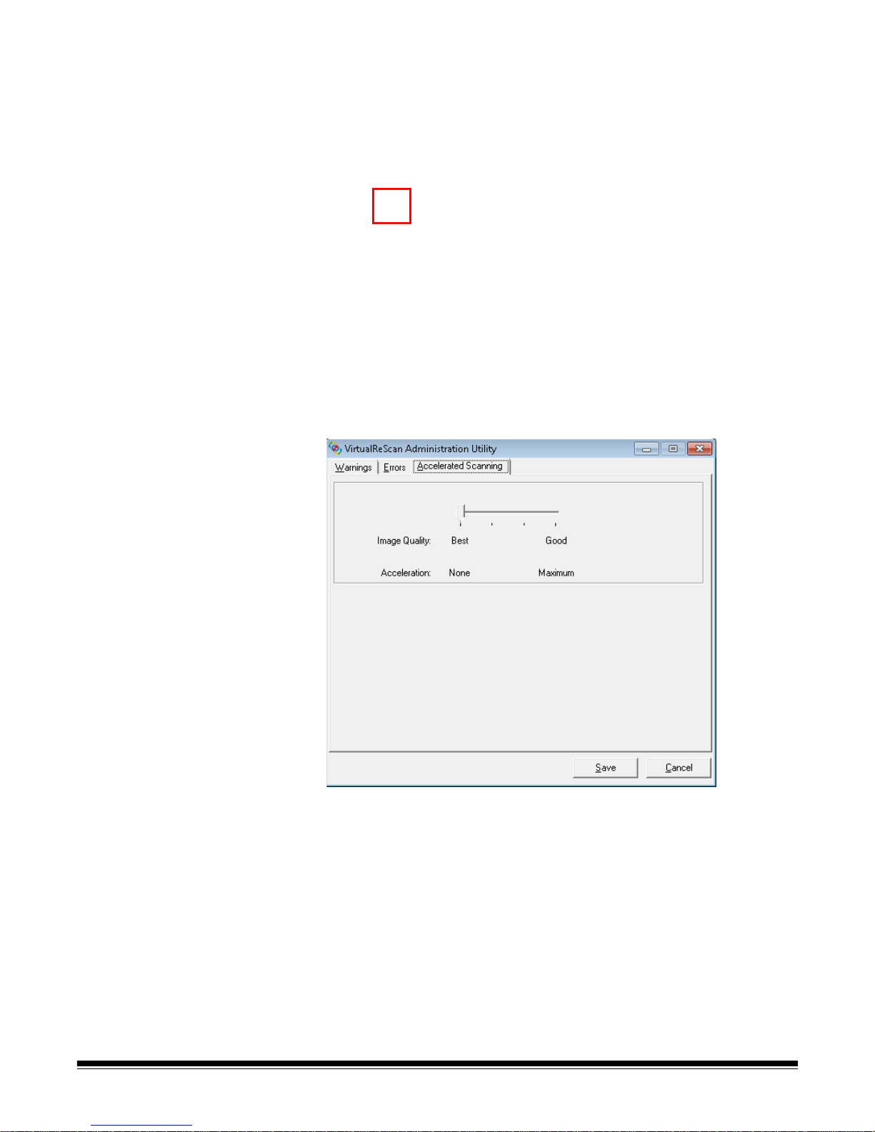
Accelerated
scanning (VRS only)
If you want to improve the scanning throughput at 300 dpi (or greater),
you can change your acceleration scanning setting. To do this:
1. If using Windows 7, from the Taskbar, click the Up arrow to access
the Admin Utility.
2. Right-click the VirtualReScan icon.
3. Select Admin Utility. The Virtual ReScan Administration Utility
dialog box will be displayed.
4. Select the Accelerated Scanning tab.
3-4 A-61662 October 201 1
5. Move the slider bar to Acceleration: Maximum.
6. Click Save.
NOTE: Changing this setting may produce a slight reduction in image
quality.
Page 21

4 Control Panel and Ngenuity Operator Utility
Contents Control panel...................................................................................4-2
Status........................................................................................4-3
Feeder table..............................................................................4-5
Custom functions......................................................................4-5
Scan monitor.............................................................................4-5
Batch control.............................................................................4-7
Ngenuity Batch Counter..................................................................4-8
Ngenuity Operator Utility.................................................................4-8
Ngenuity Operator Utility main screen............................................4-9
Menu bar.................................................................................4-10
Home screen ..........................................................................4-13
Settings button........................................................................4-15
Maintenance button................................................................4-19
This chapter provides detailed information for control panel
functionality, a description of the Ngenuity Operator Utility Batch
Control application and the Ngenuity Operator Utility (NOU).
A-61662 October 2011 4-1
Page 22

Control panel The control panel is located on the front of the scanner. The LEDs and
audible tones notify you of the current state of the scanner (e.g., power
state, maintenance needed, active features, errors, etc.).
The control panel has five sections:
•Status
• Feeder table
• Custom functions
• Scan monitor
• Batch control
4-2 A-61662 October 201 1
Page 23

Status The status area of the control panel consists of: Power Mode, Back
Door, Maintenance and Manual Feed.
Power Mode — this green LED indicates the power status or transition
between power modes.
Power State/Transition Power Mode LED
Off Off
Sleep>Powered up Blinking, fast
Ready>Active Steady green
Ready>Sleep Blinking, fast
Sleep Blinking, slow
When the scanner is in sleep mode, the Power Mode LED is the only
indicator that is active; all others are off.
Depending on the current Power Mode, the buttons on the control panel
perform different actions. The following table identifies the function of
the buttons during various Power Modes and transitions.
Power State/Transition Power Mode LED
Off Control panel and scanner are not on.
Sleep>Ready Buttons are not active during this transition.
Ready>Active All buttons perform their normal functions. Press and
hold the Stop button for 5 seconds to start the
transition process to put the scanner into sleep
mode.
Ready>Sleep The scanner is almost ready to go into sleep mode. A
momentary press of any button resets the sleep
count-down timer.
Sleep A momentary press of any button starts the Sleep >
Awake transition to awaken the scanner.
Back Door — this green LED indicates if the straight pass-through
door (located at the back of the scanner) is open or closed.
• LED Off: when the straight pass-through door is closed, the rotary
path to exit tray is in use.
• LED On: when the straight pass-through door is open, scanned
documents will exit through the straight pass-through door.
A-61662 October 2011 4-3
Page 24

Maintenance — this yellow LED indicates that maintenance or service
conditions exist in the scanner.
Maintenance LED Scanner state
Off (not lit) No maintenance is required at this time.
Slow blinking Maintenance is needed. See the section
entitled, “Ngenuity Operator Utility”
(Maintenance monitor) later in this chapter for
more information.
Fast blinking Scanner is busy or offline. This occurs when the
scanner is in off-line mode and not capabl e of
scanning (i.e., ADF test, camera calibration,
downloading firmware, imprinter cleaning, etc.).
Steady on Scanner self-test fault detected; scanner service
may be required. Use the NOU for more
information on the self test failure.
Manual Feed — this green LED indicates that the feed mode has been
changed from the default, Normal ADF (Automatic Document Feeder),
to Manual feed mode. When the LED is illuminated, the scanner is in
Manual feed mode.
Feed modes: the Ngenuity Scanner has four feed modes for feeding
documents into the scanner’s transport:
• ADF mode (default) — used for feeding batches of documents that
are similar in size and weight. After a batch of documents is placed
on the feeder table, the batch is fed automatically into the scanner’s
transport.
• Manual mode — this mode is used to feed exception documents that
cannot be fed in ADF mode (e.g.,multiple forms). In this mode, you
must feed documents manually into the scanner one at a time. When
scanning in Manual mode, the Manual Feed LED on the control
panel will be lit. See the section entitled, “Manually feeding
documents” in Chapter 3 for more information.
• Assisted Manual mode — once the scanner has entered Manual
Feed mode, the skimmer can be lowered onto the feeder table to
enable Assisted Manual mode. In this mode, the paper sensor on the
feeder table will trigger the skimmer to pull the documents into the
scanner transport. This mode can also be used to automatically feed
small batches while the scanner is in Manual Feed mode.
• Test Feed mode — used to test and verify the scanner’s feeding
capabilities, as well as to feed transport cleaning sheets. This mode
allows you to feed documents without generating a scan command
from the host PC.
4-4 A-61662 October 201 1
Unlike ADF and Manual (Assisted) modes, the Test Feed mode button
is set from within Custom Functions in the Ngenuity Operator Utility.
NOTE: With the exception of the Test Feed mode, all feed modes are
set through the scanning application’s scanner properties within
the scanning software application.
Page 25

Feeder table The Feeder Table adjustment buttons allow you to raise and lower the
feeder table to accommodate different batch sizes. The feeder table
must be empty to move to a new batch size position.
Down/Set
• Down: lowers the feeder table.
• Set: load a standard batch of documents, lower the skimmer and wait
until the table is raised. Press and hold the Down/Set button for 2
seconds.
Up — raises the feeder table. If the feeder table has documents in it,
the Up button performs no function.
Custom functions Two custom functions (F1 and F2) can be assigned via the Ngenuity
Operator Utility. Available functions are: Feed Test Batch, Page Eject
and Clean Print Head.
By default, F1 is assigned to Feed Test Batch and F2 is assigned to
Page Eject. See the section entitled, “Ngenuity Operator Utility” later in
the chapter for more information.
Scan monitor The Scan Monitor indicates that an error has occurred during scanning.
The Scan Monitor indicators are lit in yellow.
Error — indicates that an error exists that is not covered by one of the
other indicators. When an error is indicated, refer to the scanning
application for more information.
Cover — indicates that the scanner cover is open. Carefully close the
scanner cover.
If this error occurs during scanning, press Clear/Restart after you have
securely closed the cover.
Paper Jam — indicates a document jam within the scanner. Open the
scanner cover, remove any jammed documents and close the cover.
Press Clear/Restart to continue scanning.
Misfeed — indicates that a skimmer timeout or feeder jam has
occurred.
• Skimmer timeout: the skimmer is active, but the document to be
scanned did not move out of the feeder table (commonly due to roller
slippage).
• Feeder jam: the document to be scanned is fed but does not reach
the scanner transport within the expected transit time.
A-61662 October 2011 4-5
Page 26

Multifeed — when illuminated, indicates multiple or overlapped
documents have been detected entering the scanner. This indicator will
either momentarily light or remain lit depending on the multifeed
condition. For example:
• If the multifeed mode is set to Stop, the indicator remains lit and the
scanner stops when a multifeed is detected.
• If the multifeed mode is set to Notify, the indicator will light
momentarily along with a sound or prompt for each multifeed that is
detected while scanning.
MF Ignore (pre-emptive MF-ignore) — while scanning documents with
VRS or direct drivers the MF Ignore button allows you to override
multifeed detection to allow exception documents to pass through the
scanner without stopping the transport.
There are two options on the Configuration tab of the Advanced
Settings dialog box (accessed via the Settings button on the Home
screen). These options are:
• Ignore MF Alarm on the Next Page Only (default): if this option is
set, you can press the MF Ignore button once to ignore a multifeed
alarm on the next document entering the transport. If you press and
hold the MF Ignore button, any documents with a potential multifeed
condition will be ignored until the button is released.
• Ignore MF Alarm until Feeder Empties: if this option is set, you only
need to press the MF Ignore button once to ignore multifed
documents. There will be no MF alarms after this button is pressed
until the button is pressed again or the feeder is emptied of paper.
NOTE: MF Ignore when using VRS - Interactive Multifeed — the MF
Ignore button will allow you to keep the image of the multifed
page after it has been displayed on the screen.
For more information, see Chapter 5, Advanced Features.
4-6 A-61662 October 201 1
Page 27

Batch Control The Batch Control buttons allow you to restart and stop scanning.
Ready — this indicator is illuminated green when the scanner is ready
to scan.
• ADF mode: the Ready indicator will light when:
- there are no errors active
- documents are in the feeder
- the skimmer is lowered
- the feeder table has risen (or is rising) to where the skimmer is
resting on the documents in the feeder.
• Manual Feed mode: the scanner is ready to scan. The LED will
remain a steady green while the scanner is scanning.
Clear/Restart — allows you to clear an error when the error is reso lved
and resume scanning (e.g., paper is removed from the transport which
caused a paper jam).
When using VRS with the Interactive Multifeed feature enabled, use
Clear/Restart to clear a multifeed (which tells VRS to discard the
multifeed image and rescan the document).
You can also use Clear/Restart to resume scanning after a batch
pause.
Pause/Stop — used to stop feeding or stop the scanner’s transport.
• If there is no scan command queued, no documents in the transport,
and no feeding in progress, pressing Pause/Stop stops the transport
before the automatic transport timeout (20 seconds).
• If the scanner is feeding documents, pressing Pause/Stop once will
stop feeding and pause the batch. The Ready LED will blink to
indicate when the batch is paused.
• If Pause/Stop is pressed twice or pushed and held for more than one
second, a hard stop will occur (scanning stops with documents
remaining in the transport) along with a host “scanner stopped” error
(this host error will not happen if the scanner is running in Test
mode). Press Clear/Restart to resume scanning.
NOTE:If Clear/Restart is pressed before all documents are cleared
from the transport, an audible alarm on the scanner will
sound and the Paper Jam LED will light. Clear the transport
of all documents by pressing and holding the Custom
Function button that is programmed for Page Eject and then
press Clear/Restart to resume scanning (there is a slight
delay before scanning resumes).
•Use Pause/Stop to place the scanner in Sleep mode by pressing
and holding the Pause/Stop for 5 seconds or longer. This can only
be done when the scanner is idle (no scan commands queued) and
the transport is not running.
A-61662 October 2011 4-7
Page 28

Ngenuity Batch
Counter
The Ngenuity Batch Counter application can be started from
Start>Programs>Kodak>Ngenuity 9000 Scanner>Ngenuity Batch
Counter.
This application provides two resettable Batch counters which allow
you to keep track of the number of documents scanned in a batch and/
or within a shift.
The top counter can be reset to 0 by clicking the C button next to the
counter. The bottom counter (total counter) will not be reset to 0 if the
top counter is cleared. To clear both counters, click the C button next to
the bottom counter.
Ngenuity Operator
Utility
The Ngenuity Operator Utility (NOU) is the application that
communicates with the scanner to provide scanner status, configure
scanner settings and to monitor and assist with performing routine
scanner maintenance.
Be sure your scanner is properly connected and the scanner and
host PC are on before accessing the Ngenuity Operator Utility.
• From the host PC’s desktop, double-click the Ngenuity Operator
Utility icon. The NOU will run through an initialization sequence.
When communication with the scanner is established, the scanner
and connection type will be displayed on the Home screen of the
NOU.
NOTE: Any changes made to NOU settings with the scanner powered
off or disconnected from the PC will not be present when the
scanner is turned on or reconnected.
4-8 A-61662 October 201 1
Page 29

Ngenuity Operator
Utility main screen
The Ngenuity Operator Utility main screen provides a menu bar and
options for configuring basic scanner settings and tasks. The sections
that follow provide descriptions of the components on the Home screen
including the Menu bar , Home button, Settings button and Ma intenance
button.
A-61662 October 2011 4-9
Page 30
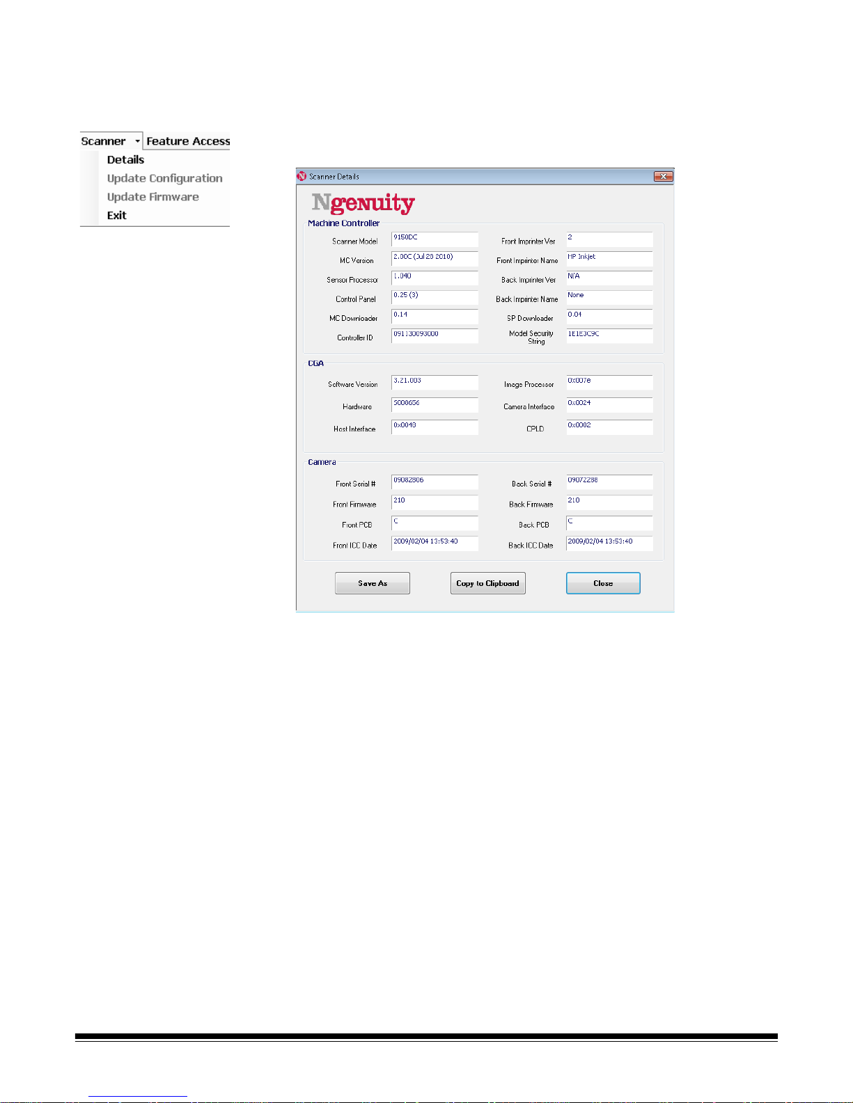
Menu bar
Scanner menu Details — displays a Scanner Details dialog box which contains
version information for scanner firmware components and camera
information, as well as scanner model identification.
• If you click Save As, the Save As dialog box will be displayed
allowing you to save this information on the host PC as a text file
(.txt).
• Copy to Clipboard allows you to copy the displayed information to
the Windows clipboard where you can paste it into another
application (e.g., pasting into an email).
• Click Close to close the Scanner Details dialog box.
Update Configuration — allows you to select and download scanner
configuration files. For use only as instructed by Kodak Technical
Support.
Update Firmware — allows you to select and download scanner
firmware updates. Firmware updates should only be performed when
instructed by Kodak Technical Support. See www.kodak.com/go/
scanners for any possible updates.
Exit — closes the Ngenuity Operator Utility.
4-10 A-61662 October 201 1
Page 31

Feature Access Feature Access provides a way of allowing full, limited or view-only
access to the features available in the Ngenuity Operator Utility. This
feature is intended to prevent some users from changing options
inadvertently on the NOU (e.g., changing multifeed detection options).
The Lock/Unlock menu allows you to temporarily unlock or lock the
configured access (Full, Limited or View Only) for the current session
without having to reconfigure.
To configure access on the PC with the NOU installed, do the following:
1. Select Feature Access>Configure. The Configure Access Wizard
dialog box will be displayed.
2. Enter the password, Ngenuity, in the Password field and click Next.
NOTE: It is recommended that you change the Kodak-supplied
password using the Change password option after you
login the first time.
A-61662 October 2011 4-11
Page 32

3. Select the option that you want to configure and click Next.
• Select feature availability — allows you to set the following
access:
- Full: all features are available.
- Limited: some features are available. If you set Limited, the
only features that will be available are: Clean Feed Rollers,
Clean Transport and Clean Optics. You will also have
access to Scanner>Details, Feature Access>Unlock and
the Help menu.
- View only: all information is visible on all main screens, but
the controls are grayed out. You will also have access to
Scanner>Details, Feature Access>Unlock and the Help
menu.
• Change password — the Change Password screen will be
displayed. Enter the new password in the Enter a new password
field, then enter the new password again in the Re-enter new
password field. Click OK, when finished.
Help menu Displays help topics for the following: View Operator Manual, Product
Support, and About Ngenuity Scanner Utility.
View Operator Manual — launches a PDF file for the Kodak Ngenuity
9000 Series Scanners User’s Guide.
NOTE: You must have Adobe Reader installed on your PC to view this
file.
Product Support — displays the Product Support dialog box which
provides technical support information and links.
About Ngenuity Scanner Utility — displays the About dialog box
which provides the Ngenuity Operator Utility application version and
copyright information.
4-12 A-61662 October 201 1
Page 33

Home screen When you click the Home button on the main Ngenuity Operator Utility
screen, the following information is displayed.
Scanner Model — displays the scanner connection status. If the
scanner is properly connected, the icon indicates a successful
connection. The scanner model and connectivity type (USB or SCSI) is
also displayed.
Imprinter Status — displays which printers are installed in the scanner,
and, for installed printers, whether an ink cartridge is detected.
The printer icon indicates imprinter configuration:
• A green check indicates the imprinter is installed and working.
• A gray X indicates an imprinter is not installed.
• A red X indicates that an imprinter is installed but not available (back
imprinter only, if pass-thru door is open).
The ink cartridge icon shows print head status:
• A green check indicates that the print head is installed and
recognized.
• A yellow ! indicates that the print head not installed or not installed
properly.
A-61662 October 2011 4-13
Page 34

Scanner Self Test — displays the results of the internal scanner fault
monitoring. A green checkmark icon indicates that no scanner faults
were detected.
A red X icon indicates one or more scanner faults were detected. The
text box will list each fault detected.
If the Self Test monitor displays a fault(s), power cycle the scanner and
check the Scanner Self Test monitor again. If the problem persists,
refer to Chapter 7, Troubleshooting.
Maintenance monitor — this section of the Home screen displays any
scanner maintenance and the type of maintenance needed (i.e., clean
transport, replace feed rollers, etc.). Monitored maintenance includes:
• Clean feed rollers
• Clean transport
• Clean optics (e.g., imaging guides, camera glass covers, sensors)
• Replace feed rollers
• Calibration of the front/back camera
• Replace imprinter ink cartridge (if optional imprinter is installed)
The Maintenance monitor also displays when or how soon specific
maintenance should occur in the form of a bar graph. See Chapter 6,
Maintenance for detailed maintenance procedures.
When a maintenance item’s pre-set interval expires, the scanner’s
Maintenance indicator will blink slowly , the icon will change from blue to
yellow and the bar graph will be red. In addition, an alert will be
displayed (yellow triangle).
NOTE: The presence of a red bar graph will not disrupt or stop the
scanner.
4-14 A-61662 October 201 1
Page 35

Resetting the maintenance reminders
If a maintenance interval expires triggering the maintenance reminder,
a hyperlink for that component will navigate you to reset and restart the
interval count. This process is necessary to ensure required
maintenance continues to be monitored appropriately.
NOTE: The alert intervals for calibrating the front and back cameras
cannot be adjusted. If an alert to calibrate the camera(s) is
displayed, click the corresponding hyperlink to perform the
calibration procedure. For procedures on calibrating the
cameras, see Chapter 6, Maintenance.
Settings button When you click the Settings button on the Ngenuity Operator Utility
main screen, the Configure Scanner Settings screen will be displayed.
A-61662 October 2011 4-15
You can configure basic scanner settings using this screen.
Sleep timeout — you can set the delay time in hours and minutes that
the scanner can be idle with full power before going into sleep mode.
The default timeout is 15 minutes; the maximum time is 4 hours.
NOTE: Sleep mode can also be entered manually by pressing the
Pause/Stop button on the control panel. See the section
entitled, “Batch Control” earlier in this chapter for more
information.
Multifeed — allows you to adjust the sensitivity when scanning Normal
or Very thin documents.
• Normal: for documents that range from thick card stock to thin
carbon copies. This setting should be used for most documents.
• Very thin: used to detect multifeeds when scanning ultra-thin
documents such as rice paper.
Page 36

Custom Functions — allows you to set a function for the F1 and F2
buttons on the control panel. Available options are:
• None: no function will be performed when F1/F2 is pressed.
• Feed Test Batch: activates the Test feed mode which is used to test
and verify the scanner’s feeding capabilities and allows you to feed
transport cleaning sheets. This is the default setting for the F1 key.
• Page Eject: will activate the transport to eject multi-fed documents or
clear the transport after a stop. This is the default setting for the F2
key.
• Clean Print Head: if you have the optional imprinter installed, will
activate the imprinter to clean the print head.
Audio — allows you to configure audio features.
• Volume: can be set to Mute, Low, Medium or High.
• Error Sound: one of three error sounds can be selected: Sound1,
Sound2, Sound3.
• Sound Type: select the kind of sound you want to hear. Selections
are Beep or Digitized Sound.
NOTE:The Digitized Sound option is not available on older model
scanners.
• Play Sound: allows you to hear the sound you have selected.
4-16 A-61662 October 201 1
Page 37

Advanced settings • Select the Advanced button on the Configure Scanner Settings
screen to access additional scanner settings.
Border Adjust tab: allows you to adjust the image boundaries or
borders of a scanned image which is determined by autocrop. Each
side of a scanned image can be individually adjusted by cropping or
adding extra black border. This only affects images as part of the
scanning process. This adjustment cannot be made to an existing
image.
The range of adjustment is between -0.500 to 0.500 inches; negative
values crop, and positive values add extra border. The default values
are 0.000 for all sides.
A-61662 October 2011 4-17
Page 38

Configuration tab: allows you to configure advanced scanner
features.
Front Panel MF Ignore Button Mode — allows you to select how the
MF Ignore button on the control panel will operate.
• Ignore MF Alarm on the Next Page Only: when you select this
option, it allows you to momentarily turn off the multifeed alarm on th e
next document entering the transport by pressing the MF Ignore
button on the control panel. This is helpful if you know that a false
multifeed (i.e., sticky note is attached to a page or there is an
envelope in the batch) is about to be scanned. In this mode, you can
continue to hold the MF Ignore button down and the scanner will
continue to ignore any multifeeds over multiple pages. When the
button is released, MF Ignore turns off.
• Ignore MF Alarm until Feeder Empties: when you select this
option, it configures the MF Ignore button to temporarily turn off the
multifeed alarm during the next batch. This is helpful if you know that
false multifeeds will occur over several or all documents in a batch. In
this mode, press the MF Ignore button once to toggle multifeed
ignore on, and press the button again to turn it off. If MF Igno re is on,
it will automatically be turned off when the feeder empties.
When finished, click Save to save your changes and close the
Advanced Settings window.
4-18 A-61662 October 201 1
Page 39

Maintenance button When you click the Maintenance button on the Ngenuity Operator
Utility main screen, the Maintenance screen will be displayed.
This screen provides scanner statistics for total hours, total pages fed
and total pages scanned, and also allows you to configure reminders
for required maintenance tasks to ensure optimal performance.
Scanner Statistics — provides statistics for Total On Time (awake
and sleeping), Total Pages (fed) and total Scanned Pages. These
totals are updated every 2 seconds.
Configuration Maintenance Reminders — allows you to set the
interval values for triggering the reminders that are visible in the
Maintenance section of the Home screen.
Intervals can be set for cleaning the feed rollers (pick, drive and
separation rollers), the transport rollers, the optics and to replace the
feed rollers (pick, drive and separation rollers). These reminders can
also be individually enabled and disabled.
To enable and adjust a maintenance reminder, click the check box next
to the corresponding component and use the up/down arrows in the
Page Interval column to change the value. Click Save to save your
changes or Restore to reset the values to the previously saved settings
The available interval settings and their defaults are:
Reminder Range Default
Clean Feed Rollers (pick, drive and separation rollers) 1K - 50K 10K
Clean Transport Rollers 5K - 100K 50K
Clean Optics (camera covers, imaging guides, sensors) 5K - 150K 50K
Replace Feed Rollers (pick, drive and separation rollers) 100K - 900K 600K
Maintenance Operations — provides access to additional
maintenance and troubleshooting operations.
A-61662 October 2011 4-19
Test Patch Reader — launches the patch reader test wizard, which
allows you to feed patch code sheets and determine if the pa tch
patterns are being accurately recognized by the scanner.
Page 40

5 Advanced Features
Contents Accessing Advanced features.........................................................5-2
Advanced Properties dialog box.....................................................5-3
Color screen...............................................................................5-4
Picking Rectangle screen...........................................................5-5
Rotation screen ..........................................................................5-6
Toggle Color Mode screen..........................................................5-7
Document Setup screen.............................................................5-8
Advanced Color screen............................................................5-10
Multifeed screen.......................................................................5-11
About screen ............................................................................5-13
This chapter provides information about advanced features that can be
used with Kodak Ngenuity 9000 Series Scanners. The controls for
operating the Advanced Features are accessible within the
®
VirtualReScan
(VRS) Interactive Viewer.
NOTE: When VRS is not installed, similar settings can be found in the
Direct ISIS and TWAIN settings.
A-61662 October 2011 5-1
Page 41

Accessing Advanced
features
To access the VRS Interactive Viewer, Ngenuity VRS Professional
software must be loaded on the host PC that the scanner is connected
to. VRS Professional will be active when the scanning application being
used is launched and a VRS scan source is selected.
NOTE: This User’s Guide only documents the VRS-based scanning
setup.
For scanning applications that utilize the VRS-based driver, the VRS
icon will be displayed in the Windows Taskbar on the host PC when the
scan source (scanner) is selected.
To launch the VRS Interactive Viewer:
1. Right-click on the VRS Taskbar icon and select Preview.
The VirtualReScan Interactive Viewer window will be displayed.
2. Within the Interactive Viewer, access the Advanced features by
clicking the Scanner Driver Settings icon ( ) to display the
Advanced Properties window.
5-2 A-61662 October 201 1
Page 42

Advanced Properties
dialog box
The features on the Advanced Properties dialog box can be used to
control scanner-specific features that are not accessible through the
Kofax VRS or scanning application screens. For example, if you have
health forms where you need to drop out a form color or if you have
documents with labels that cause false multifeed alarms, etc., you can
change the scanner’s settings on the Advanced Properties dialog box
to enable Multifeed detection or electronic color dropout scanner
features. These settings can be saved as part of a profile. Any settings
made on the Advanced Settings screen will override the same settings
defined in a saved profile. For more information on scanning with VRS
Test Application and Profiles, see the Kofax VRS 4.5 (or newer) User’s
Guide.
NOTE: Any settings made in the Advanced Properties dialog box must
be saved in a profile or they will be lost when the application is
closed.
Some of the settings that can be made using the Advanced Properties
dialog box include: color dropout, multifeed, rotation, document setup
(i.e. allowing for large skew, etc.)
NOTE: If you have the optional Imprinter, see Appendix B for
installation procedures, maintenance and instructions for using
the front page (pre-scan) and back page (post-scan) imprinter.
To display the functions contained within a menu, click the
corresponding hyperlink.
A-61662 October 2011 5-3
OK — saves any changes and closes the window.
Cancel — reverts the settings back to the last saved settings.
Help — displays a brief description of the controls on the Advanced
Properties window.
Page 43

Color screen The Color screen allows you to dropout a form's background so that
only the entered data is included in the electronic image (i.e., remove
the form’s lines and boxes).
Front Side Dropout Color — select the desired dropout color you
want to eliminate from the front side. Selections are: None, Red, Green
or Blue.
Back Side Dropout Color — select the desired dropout color you want
to eliminate from the back side. Selections are: None, Red, Green or
Blue.
JPEG Compression — click Enabled to select a JPEG Quality option.
Choices are:
• Good: a fair amount of compression but still produces acceptable
image quality (smallest file size).
• Better: some compression which produces decent image quality.
• Best: minimal compression which produces very good image quality
(largest file size).
• Custom: select this option to customize your JPEG compression
values. When selected, the YUV and Value percent options are
available.
- YUV is a type of color space used in JPEG compression. The 4-2-2
selection (default) uses downsampling and generates smaller files
compared to the 4-4-4 selection, which uses no downsampling
(keeps as much image color data as possible) and generates large
files.
5-4 A-61662 October 201 1
- Value: a high percentage value compresses the least, and
generating larger files, while a low percentage value compresses
the most, generating smaller files, which can result in lower quality
images.
Page 44

Picking Rectangle screen The Picking Rectangle screen provides the following options:
Front Side/Back Side — allows you to define the area to be imaged by
selecting a value in the Width and Height drop-down boxes and its
offset from the upper left corner of the image (defined by the Top and
Left values). The picking rectangle is relative to the cropped image
such that a value of Top=0.00 and Left=0.00 will always be the very left
corner of the lead edge of the page that was fed into the scanner. The
resulting image is a cut out of the original, larger image. Therefore, if
you scan a letter-size page and have Letter paper size selected, you
will get a rectangular cut out from that image, the location and size of
which is determined by these values.
A-61662 October 2011 5-5
Page 45

Rotation screen The Rotation screen provides the following options.
Front Side/Back Side — allows you to rotate the scanned image 0, 90,
180 or 270 degrees. 0 is the default.
5-6 A-61662 October 201 1
Page 46

Toggle Color Mode screen The Toggle Color Mode screen provides the following features.
Preferences
• Use patch code detection to toggle color mode — check this box
to enable toggle patch detection.
• Start in Black and White — when checked, the batch will
automatically start in Black and White mod e, o therwise th e bat ch will
start in either color or grayscale as determined by the basic batch
setup scan mode.
• Delete images from toggle patch sheet s — when checked, images
for the toggle patch sheets will be automatically deleted by VRS.
• Enable patch confirmation tone — when checked, a confirmation
tone will signal that a patch has been recognized.
If grayed out, this
feature is not currently supported by the scanner firmware.
These patch codes are recognized when toggle color mode is enabled:
A-61662 October 2011 5-7
Black & White Settings
• Black and White DPI — select the DPI to use when the scanner
switches to Black and White mode. This can be different than the
color (or grayscale) DPI selected elsewhere for the batch. For
example, basic batch setup selects Color 150 dpi, but black and
white images use 300 dpi. Refer to the Kofax VRS Users Guide or
VRS online help for more information regarding this feature.
Page 47

Document Setup screen The Document Setup screen provides the following options.
Document Types — allows you to change the transport speed to
accommodate the feeding needs of various document types.
• Normal: highest transport speed for scanning standard document
types. This is the full performance mode.
• Fragile/Difficult: lower transport speed which is useful for delicate
documents that can easily tear.
• Thick or Envelope: for scanning thick paper or envelopes.
• Tri-Fold: for scanning tri-fold documents.
NOTE: Document types other than Normal may reduce scanner speed.
Allow Large Skew — if enabled, this option maximizes image data
capture for documents that are fed into the scanner highly skewed,
helping to eliminate clipped or missing corners.
Very Long Document — when enabled, this option allows scanning of
extremely long documents (up to 200 m) into individual images. The
size of the images is determined by the Paper Size setting in the
scanning application. Documents longer than the selected paper size
will be imaged as segmented multiple images.
NOTES:
• Starting with scanner firmware version 2.10, the Pause/Stop button
on the scanner control panel can be used in Very Long Document
mode to stop the document in progress allowing you to make any
required feeding adjustments. The document can then be restarted
using the Clear/Restart button.
5-8 A-61662 October 201 1
• The Very Long Document option does not support the simultaneous
use of some other options offered through VRS ImageControls and
Direct Drivers.
Page 48

Following is a table that identifies those other controls as well as how
the scanner and software handle the conflict when you attempt to use
them together.
Conflicting Controls Resolution
Single Page Scan The scan is terminated and an error message is displayed. Very
Long Document is not supported with single-page scanning. Use
the batch scan command.
VRS Administration Utility Warning tab
On Errors QC Mode The document is scanned ignoring the On Errors QC Mode op tions
Every Page QC Mode The scan is terminated and an error message is displayed.
First Page QC Mode The scan is terminated and an error message is displayed.
Deskew and Auto Crop The document is scanned ignoring the Deskew and Auto Crop
Image Rotation of 90, 180, or
270 degrees
Auto Orientation The scan is terminated and an error message is displayed.
Picking Rectangle For best results, do not use Very Long Document and Picking
Automatic Color Detection For best result s, do not use Very Long Document and Automatic
Advanced Clarity For best results, do not use Very Long Docume nt and Advanced
The document is scanned ignoring the warning conditions that are
set. No error message is displayed.
that are set. No error message is displayed.
options that are set. No error message is displayed.
Do not select rotation options if scanning using Very Long
Document.
Rectangle at the same time.
Color Detection at the same time.
Clarity at the same time.
Ignore Holes/Ragged Edges — click Enable to adjust the entry and
exit sensors so they ignore holes on the leading or trailing edge of a
document (e.g., three-hole punched paper), that may cause the
scanner to detect false starting or trailing edges of a document. If you
are receiving Page Sensor or Peripheral Malfunction errors, enable this
feature and adjust the value until the error disappears.
This option can be set using a measurement in inches or millimeters
with a range of 0.0 to 1.7 inches (0 to 43 mm). Set Ignore Holes/
Ragged Edges to a width slightly larger than the holes in the paper (or
whatever may be causing the false detection of the leading or trailing
edges of a document).
A-61662 October 2011 5-9
NOTE: Enabling Ignore Holes/Ragged Edges may reduce scanning
throughput.
Front/Back Negative Image Enable — allows you to reverse black
with white when scanning in black and white or to invert grayscale
levels when scanning in grayscale. This control is not supported when
scanning in color.
Dark Background Crop — in addition to auto-crop and deskew, this
option could be considered as an alternative for dark documents. The
default setting should satisfy most of these exception cases.
Page 49

Advanced Color screen The Advanced Color screen provides the following options.
If the color on your images is not as expected, you can use the
Advanced Color screen to make color adjustments to meet your
scanning needs.
Camera Modes
• sRGB: uses specific camera gamma to achieve the best
approximation of sRGB color response.
NOTE:This setting applies to the camera output only; any post-
capture image processing settings affect the color content of
the final output file.
ICC: select this option to cause VRS to embed ICC profile data into the
image file. ICC profile data is used by some viewing or printing
applications to compensate or adjust colors for optimal quality . ICC data
is useful only for applications that are ICC-profile aware. To properly
view the images, the viewing application must be ICC-profile aware.
NOTE: Do not use other post-processing color adjustments in
combination with this option enabled.
For the ICC profile data to be successfully embedded, the scanning
application must:
• be an ImageControls, Direct ISIS or Direct TWAIN application
• be set up for color scanning
• be set up to store TIFF, JPEG or PDF image file types
• not use VRS Automatic Color Detection (images may be converted to
black and white)
5-10 A-61662 October 201 1
Page 50

Gamma (default) — allows you to specify a specific camera gamma
(1.0 - 2.5). The camera gamma value can be entered or selected by
moving the slider to the desired value.
Select a lower gamma value to enhance color saturation for bright
colors and a higher gamma value to enhance color variations for dark
colors. For most documents the camera gamma should be kept at the
default value of 1.3.
NOTE: Selecting one of these Camera Mode options activates that
option for both the front and back camera.
Multifeed screen The Multifeed screen provides the following options.
Multifeed Mode — determines the response of the scanner if a
multifeed occurs.
• Off: no multifeed detection occurs. Scanning continues and all
scanned images are retained.
• Notify: the scanner responds to the multifeed by sounding an audible
alarm and momentarily lighting the Multifeed LED on the control
panel. Scanning continues, the multifeed is ignored and t he image of
the multifeed document is retained.
A-61662 October 2011 5-11
Page 51

• Stop: when a multifeed is detected, the scanner sounds an audible
alarm, the Multifeed LED lights steady and the scanner’s transport
stops. You can delete or keep the multifeed image.
The VirtualRescan Auto Resolve Manager will display the front of
the image of the document that triggered the multifeed alarm.
- T o dele te the image: select the Custom Function button that is set
to Page Eject (F1 or F2) to eject the multifeed document from the
transport. Correct whatever caused the multifeed and place the
multifeed document back in the feeder on top of the batch of
documents to be scanned, and press the Clear/Reset button on
the control panel to restart scanning.
- To keep the image: press the MF Ignore button on the control
panel. The scanner will automatically eject the multifeed
document and continue scanning, keeping the multifeed image.
NOTE: If the scanner’s audio feature has been set to Mute, you will
not hear the alarm that occurs with the Notify and Stop
options when a multifeed is encountered.
Enable Sensors — allows you to enable or disable the Left, Center
and Right sensors that detect a multifeed condition. One or more of
these sensors can be enabled/disabled at any time. If all three are
disabled, the Enable Sensors control grays out and the Multifeed Mode
control automatically is set to Off.
Ignore by Size — allows you to set the maximum size of a multifeed
that will not trigger a multifeed error. This is used to scan documents
with labels or stickers (mailing labels), documents with taped
photographs or receipts while multifeed detection is active.
Ignore by Size can be set in inches or millimeters, with a ran ge of 1.0 to
25.5 inches (25-647 mm). The default setting for this control is
1.0 inch (25 mm).
5-12 A-61662 October 201 1
Page 52
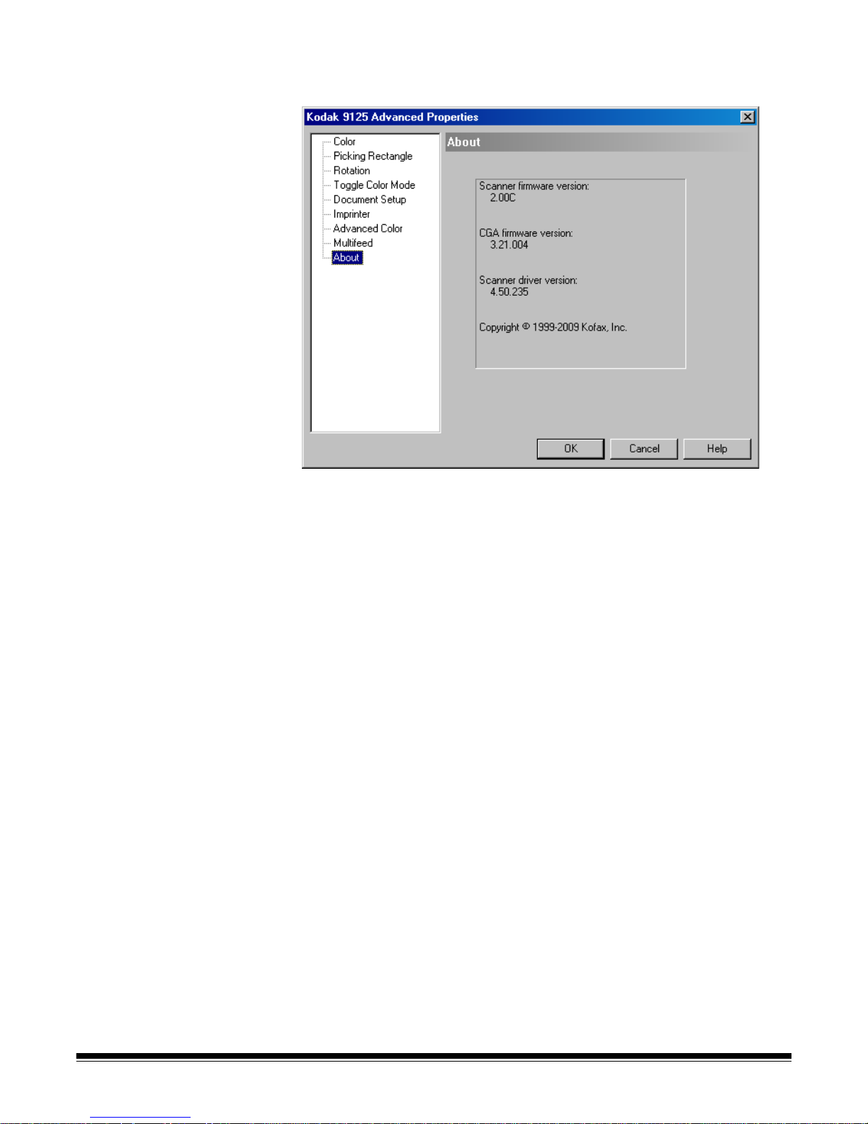
About screen The About screen displays the scanner version and copyright
information.
A-61662 October 2011 5-13
Page 53

6 Maintenance
Contents Maintenance schedule ...................................................................6-2
Cleaning supplies............................................................................6-2
Cleaning procedures.......................................................................6-3
Cleaning the feed rollers.............................................................6-4
Cleaning the optics.....................................................................6-7
Cleaning the transport..............................................................6-11
Replacement procedures..............................................................6-12
Replacing tires..........................................................................6-12
Replacing the pre-separation pad ............................................6-13
Replacing the imaging guides ..................................................6-13
Lamps (LEDs)...........................................................................6-13
Camera calibration ........................................................................6-14
Supplies and consumables...........................................................6-16
Performing routine maintenance will ensure optimal image quality and
prolong the life of your scanner.
The Maintenance monitor on the Home screen of the Ngenuity
Operator Utility (NOU) provides reminders as to when scanner
maintenance is required.
Based on the intervals set, the Maintenance LED on the control panel
will also blink. To turn the Maintenance LED off and to reset the interval
count for future reminders, click on the link to the right of the expired
maintenance item after each maintenance procedure is completed.
A-61662 October 2011 6-1
Page 54

Maintenance
schedule
The following table is a recommended schedule for performing basic
maintenance functions. Some procedures may need to be performed
more frequently depending on your operating environment and the
types of documents being scanned.
Maintenance Recommended Range Symptoms
Clean feed rollers: pick, drive,
and separation roller
Clean transport rollers 50,000 pages 5K - 100K • Multifeeds
Clean Optics: imaging guides,
camera glass covers, sensors. The lamps are not part
of the optics. The lamps
(LEDs) should not be cleaned
or wiped with any type of wipe
or solvents.
Camera calibration Every 1200 hours N/A Poor color image quality (e.g., white tinted
Replace tires 600,000 pages 100K -
10,000 pages 1K - 50K • Skewed documents
• Multifeeds
• Feeder jams
• Transport jams
• Elongated images
50,000 pages 5K - 150K Glass Camera Covers / Imaging Guides
• Streaks in the image
• Reduced OCR/ICR/Barcode recognition
rates
• Blurred images
Page Sensors
• Entry/exit sensor errors
Feeder Sensors
• Feeder table does not lower when out of
paper
green, red or blue)
• Noticeably worn tires
900K
• Page skewing, multifeeds and paper
jams continue to occur after cleaning is
performed
Ink cartridge(s) - only relevant
if optional imprinter is
installed
Approximately
34,000 pages (can
vary depending on
number of characters per page and
font used, etc.)
N/A Poor print quality
Cleaning supplies Scanner consumables and cleaning supplies are available from
resellers and web merchants.
• Roller Kit (Small, Medium, Large)
• Blower brush
• Transport cleaning sheets
•Swabs
• Roller Cleaning Pads
• Staticide Wipes
6-2 A-61662 October 201 1
Page 55

Cleaning procedures Cleaning your scanner and performing preventative maintenance on a
regular basis is required to ensure the best possible image quality.
Some document types generate more paper dust and debris and may
require more frequent cleaning.
Before cleaning your scanner or replacing consumables, review the
following information:
• Turn the scanner off and unplug it from the wall outlet before
performing maintenance procedures.
• Remove any jewelry or any items from hands or wrists that could
become caught on internal scanner components.
• Some debris from the rubber tires on the pick and drive rollers and
separation roller is normal. Tire debris does not always mean that
the tires are worn or damaged. After cleaning, inspect the tires for
wear and replace the separation roller tires or pick and drive roller
tires if necessary.
• When cleaning rollers/tires, allow the rollers/tires to dry completely
before scanning.
• Use only the recommended cleaning supplies. Using unapproved
cleaning fluids or solvents may damage the rubber tires.
• Do not use cleaners in confined areas; use with adequate
ventilation.
• Do not use flammable compressed aerosols on or around the
scanner.
NOTE: To access the Material Safety Data Sheet (MSDS), you will
need to provide the catalog number or keyword of the
supply. See “Supplies and Consumables” later in this
chapter for catalog numbers.
A-61662 October 2011 6-3
Page 56

Cleaning the feed rollers Feed rollers include the pick roller, drive roller and separation roller.
All feed rollers should be cleaned and/or replaced at the same time to
ensure optimal scanner function. Maintenance reminder intervals (both
cleaning and replacing) are based on all feed rollers having the same
life cycle.
Cleaning the pick and drive rollers
When the feed rollers become dirty, they may begin to slip on paper or
cause multifeeds. To prevent feeding problems and avoid rubber tire
replacements, it is recommended that you clean the tires on the rollers
every 10,000 pages or as needed. Different document types, the
condition of the documents being scanned, and t he volume of scanning
may require more frequent cleanings.
Always remove the rollers from the scanner before cleaning to ensure
best results.
1. Turn off the scanner and unplug it from the wall outlet.
2. Open the scanner cover.
3. Remove the pick roller by rotating the release lever up, push the
pick roller to the right and remove it.
NOTE: Before cleaning the pick and drive rollers, inspect the tires.
If the tires show signs of wear or damage, replace them.
See “Replacement procedures” later in this chapter.
6-4 A-61662 October 201 1
4. Using a roller cleaning pad, scrub the roller tires using a side-to-side
motion. Rotate the roller to clean the entire surface.
IMPORTANT:The roller cleaning pad contains sodium lauryl ether
sulfate and sodium silicate which can cause eye
irritation. Wash hands after use. Refer to the MSDS
for more information.
Page 57

5. Re-install the pick roller.
6. Remove the drive roller by pushing the roller to the right. Hold the
drive roller shaft in place and slide it off the shaft. Gently release the
drive roller shaft back into position.
7. Using a roller cleaning pad, scrub the roller tires using a side-to-side
motion. Rotate the roller to clean the entire surface.
8. Re-install the drive roller.
Cleaning the separation roller
9. Pull the separation roller door forward and remove the separation
roller.
NOTE: The separation roller cover is spring-loaded. Hold the
separation roller cover back until you remove the
separation roller, then gently lower the roller cover back in
place.
10.Using a roller cleaning pad, scrub the roller tires using a side-to-side
motion. Rotate the roller to clean the entire surface.
11. Re-install the separation roller by aligning the slots on the
separation roller with the holders.
A-61662 October 2011 6-5
Page 58

12. Close the scanner cover and reset the maintenance reminder by
clicking on the Clean Feed Rollers link on the Maintenance
monitor.
13. Click Yes on the dialog box to confirm the feed rollers have been
cleaned. The reminder will be reset for the next required
maintenance session.
6-6 A-61662 October 201 1
Page 59
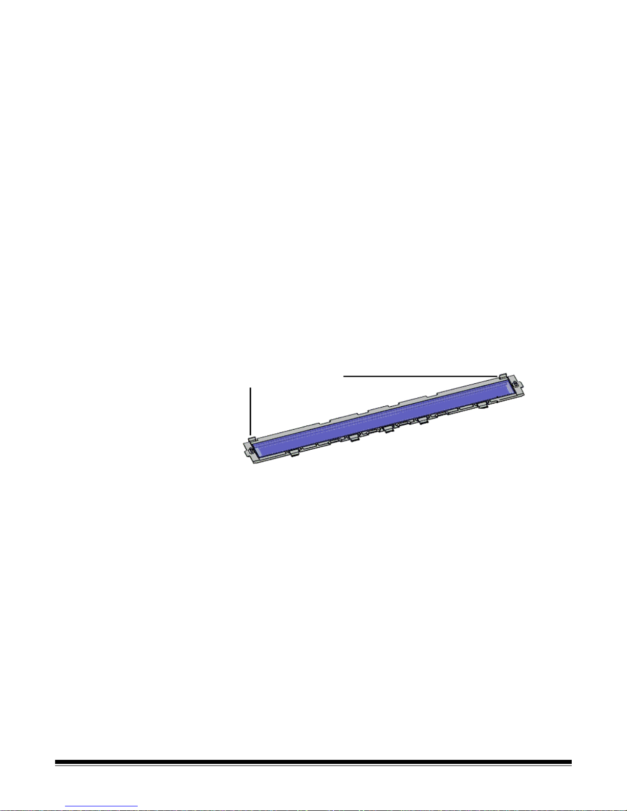
Cleaning the optics Optics include the imaging guides, camera glass covers and
Fastening clips (2)
sensors. All of the optics components should be cleaned at the same
time.
NOTE: The lamps are not part of the optics. The lamps (LEDs) should
not be cleaned with wipes or solvents.
Cleaning the imaging guides and camera glass covers
To prevent streaks in images, reduced OCR/ICR/Barcode recognition
rates, blurred images, etc., you should clean the imaging guides every
50,000 pages.
The two imaging guides which are inside black, plastic frames are
located in the top and bottom transport trays. When removing an
imaging guide for cleaning or replacement, the entire assembly
(imaging guide and frame) are removed and replaced as one piece.
Clean the camera glass covers at the same time you clean the imaging
guides.
CAUTION: Do not remove the imaging guide from the black frame.
1. Open the scanner cover.
2. Gently pull the 2 fastening clips that secure the top imaging guide
towards the front of the scanner to release and remove the imaging
guide from the transport.
A-61662 October 2011 6-7
3. Using a Staticide wipe, clean both sides of the imaging guide. Be
careful not to touch the cleaned glass.
IMPORTANT:Staticide wipes contain isopropanol which can cause
eye irritation and dry skin. Wash your hands with soap
and water after performing maintenance procedures.
Refer to the Material Data Safety Sheet (MSDS) for
more information. The MSDS is available on the
Kodak web site at www.kodak.com/go/MSDS.
Page 60

4. With the imaging guide still out of the scanner, locate the glass
Imaging guide removed
Camera cover
LEDs
Lamp
Imaging
Five guides slide underneath the transport tray
Fastening clips
guide
camera cover between and below the LED lamps.
5. Using a clean dry swab, gently wipe across the glass camera cover
to remove any dirt and dust particles. Do not spray any solvent on
the swab unless a dry swab will not remove the residue on the
glass. If you need to use solvent, spray the solvent on the swab. Do
not spray solvent in or around the internal components of the
scanner.
6. When the camera cover is clean, re-insert the cleaned imaging
guide into the scanner by holding the frame of the imaging guide so
that the fastening clips are on the back side of the imaging guide.
Slide the guides under the transport tray towards the feeder table
and ease the back side of the imaging guide into position.
7. Repeat Steps 2 - 6 to clean the bottom imaging guide and bottom
camera cover.
8. When finished, close the scanner cover.
6-8 A-61662 October 201 1
Page 61

Cleaning the sensors
Feeder sensor
Top or front page tray assembly
Gap sensor
Page entry
sensors (3)
Pass thru
sensor
There are 7 sensors that require regular cleaning. Use only the
supplied blower brush to clean these sensors. Do not use any type of
cotton swab or cloth as these items may leave lint in the sensors.
9. Feeder sensor: Place the brush end of the blower brush into the
feeder sensor area and squeeze the blower brush several times to
clean the feeder sensor.
10. Gap sensor, page entry sensors and pass thru sensor: Open
the scanner cover to clean these 5 sensors by placing the brush
end of the blower brush into the each sensor area and squeeze the
blower brush several times to clean.
A-61662 October 2011 6-9
Page 62
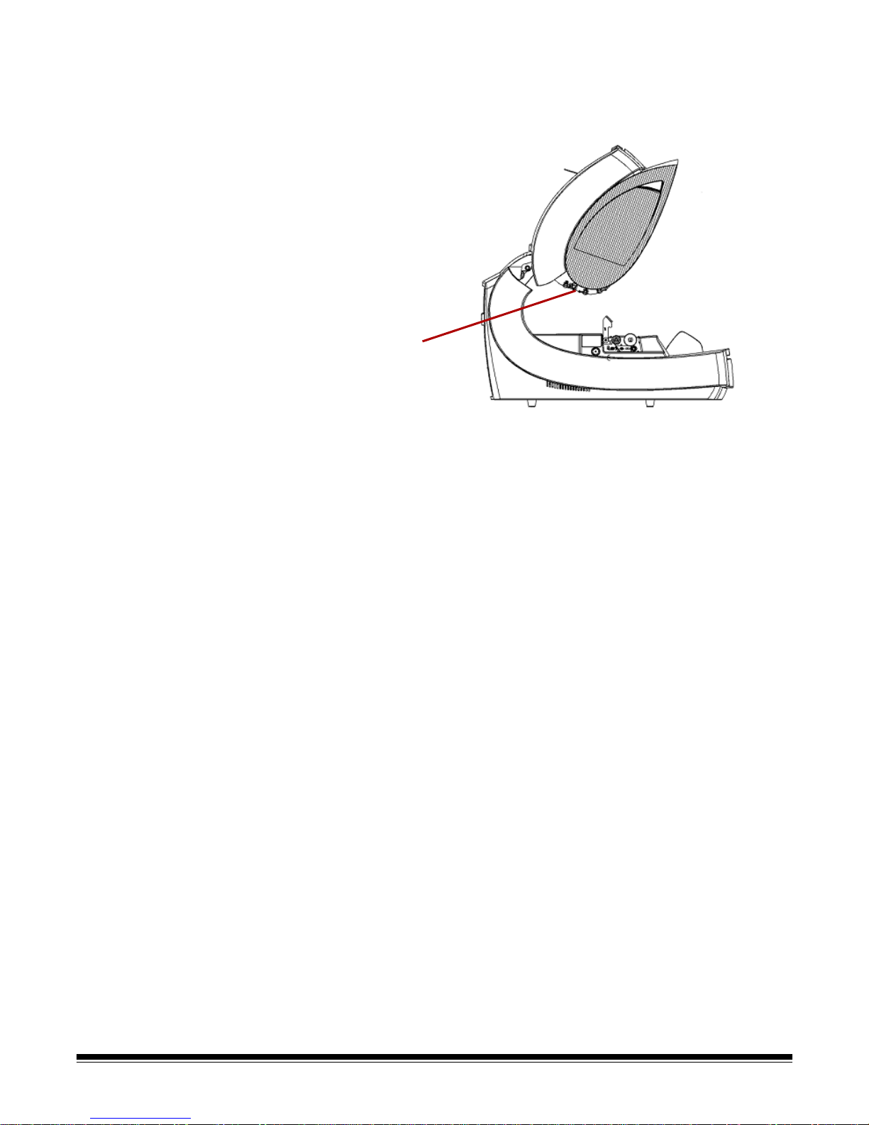
11. Exit sensor: The exit sensor is located on the transport toward the
Exit sensor
back of the scanner. Clean the exit sensor by placing the brush end
of the blower brush into the exit sensor area and squeeze the
blower brush several times.
12. When all sensors are clean, close the scanner cover and reset the
maintenance reminder by clicking on the Clean Optics link on the
Maintenance monitor.
6-10 A-61662 October 201 1
13. Click Reset on the dialog box to confirm the optics have been
cleaned. The reminder will be reset for the next required
maintenance session.
Page 63

Cleaning the transport Over time, the transport will become dirty and may feed documents
erratically or skew the documents as they enter the scanner. T o prevent
erratic feeding, clean the transport every 50,000 pages or as needed.
NOTE: It is recommended that you clean the imaging guides again after
cleaning the transport with a transport cleaning sheet.
1. Establish communication between the scanner and the Ngenuity
Operator Utility.
2. Verify that one of the Custom Functions (F1 or F2) is set to Feed
Test Batch.
3. Press F1 or F2 key depending on which key is assigned to “Feed
Test Batch”. This will start the scanner transport. By default, the F1
key is assigned the Feed Test Batch function.
4. Feed the transport cleaning sheet in landscape orientation into the
scanner transport.
5. Observe the cleaning sheet, and run it through the transport again,
changing its position slightly each time, until the tires leave no dark
streaks.
6. Turn the transport cleaning sheet over and run it through the
scanner transport two times.
7. Press and hold the Pause/Stop button (2-3 seconds) until the
scanner stops running.
8. Press the Clear/Restart button.
9. When finished, discard the transport cleaning sheet. After running
the cleaning sheet, inspect the imaging guides. It may be necessary
to clean off any residue from the cleaning sheet that may be on the
imaging guides.
A-61662 October 2011 6-11
Page 64

Replacement
procedures
Replacing tires With proper cleaning, tire life of the pick roller, drive roller and
This section provides procedures for replacing the following parts: the
feed rollers, the pre-separation pad and the imaging guides. When
replacing parts, turn the scanner off by pressing the power switch
located in the back of the scanner and unplug the power cord from the
wall outlet.
separation roller is approximately 600,000 pages. Different document
types, the condition of the documents being scanned, and the volume
of scanning may alter that estimation.
All tires on the pick roller, drive roller and separation roller should be
replaced at the same time. See the section entitled, “Cleaning the feed
rollers” earlier in this chapter for procedures on removing and installing
the feed rollers.
1. Open the scanner cover.
2. Remove the pick and drive rollers.
3. Gently remove each tire from the pick and drive rollers and dispose
the old tires.
4. Install each new tire by gently pulling it over the core. The tires do
not need to be installed in any specific orientation.
IMPORTANT:Do not overstretch the tire; it may tear.
5. Re-install the pick and drive rollers.
6. Pull the separation roller door forward and hold it in place while you
remove the separation roller; gently release the separation roller
door back in place.
7. Remove each tire from the separation roller and dispose the old
tires.
8. Re-install the separation roller and verify that the separator roller is
seated properly.
9. Close the scanner cover.
10. When all tires have been replaced, reset the maintenance reminder
by clicking on the Replace Feed Rollers link on the Maintenance
monitor.
11. Click Yes on the dialog box to confirm the tires/rollers have been
replaced. The reminder will be reset for the next required
maintenance session.
6-12 A-61662 October 201 1
Page 65

Replacing the preseparation pad
Change the pre-separation pad when the frequency of multi-fed
documents increases.
1. Open the scanner cover.
2. Remove the pre-separation pad by lifting the pad up and out of
position.
NOTE: The pre-separation pad fits snuggly in place; therefore, a
little force may be required to remove it.
3. Install the new pre-separation pad. Be sure it snaps into place.
4. Close the scanner cover.
Replacing the imaging
guides
Replace the imaging guides when they become damaged or heavily
scratched. See the section entitled, “Cleaning the optics” earlier in this
chapter for detailed procedures about removing the imaging guides.
1. Open the scanner cover.
2. Gently pull the 2 fastening clips that secure the top imaging guide
towards the front of the scanner to release and remove the imaging
guide from the transport.
3. Install the new imaging guide into the scanner by holding the frame
of the imaging guide so that the fastening clip s are on the back side.
Slide the guides under the transport tray towards the feeder table
and ease the back side of the imaging guide into position.
4. Repeat Steps 2 and 3 to replace the bottom imaging guide.
5. Close the scanner cover.
Lamps (LEDs) IMPORTANT:The LEDs on Ngenuity scanners should NOT be cleaned
or wiped with any type of wipes and/or solvent.
The LED illumination system on Ngenuity Scanners should last the life
of the scanner with normal use. If something happens that requires the
replacement of the LEDs, contact Kodak Technical Support.
A-61662 October 2011 6-13
Page 66

Camera calibration Camera calibration is important for maintaining consistent image quality
and should be performed periodically in order to maintain optimum
white balance and camera levels. The scanner's maintenance LED or
the NOU on the Maintenance screen will indicate the need for camera
calibration.
It is recommended that you always calibrate both cameras together,
although they can be calibrated independently. Calibrating both
cameras takes approximately 4-7 minutes.
NOTE: Before calibrating the camera(s):
• Clean the scanner optics thoroughly. See the section
entitled, "Cleaning the optics" earlier in this chapter.
• Make sure the scanner is running in Ready mode (not in
Sleep mode) for at least 5 minutes prior to calibrating.
• Shut down any other scanning application connected to the
scanner.
1. Open the Ngenuity Operator Utility and establish communication
with the scanner.
2. Click on one of the Calibrate links in the Maintenance section of the
NOU Home screen.
The Camera calibration dialog box will be displayed.
3. Click Both, and then click Start. The message, Lift skimmer, then
manually feed the calibration sheet into scanner will be
displayed.
6-14 A-61662 October 201 1
Page 67

4. Lift the skimmer and make sure the feeder tray is empty. The
scanner will automatically go into Manual Feed Mode, the feeder
table will rise and the transport will begin to run.
5. Once the feeder table has risen to the full-up position, feed a single,
clean white calibration sheet (Part No. 5K0449 from CAT No.
199 8103) into the scanner transport in the orientation indicated on
the sheet. A counter and a progress bar will indicate the calibration
progress.
NOTE: Do NOT open the scanner cover , shut do wn the sca nner or
host PC while calibration is in progress.
6. When the calibration function has completed all steps successfully,
a confirmation screen will be displayed.
7. Click Close. The calibration sheet will be automatically ejected from
the scanner.
NOTE: If the confirmation screen states that the calibration was
unsuccessful, turn off the scanner, close the NOU and recheck
the scanner’s optics. After cleaning, inspect the imaging guides
for contamination, excessive scratches or gouges, or dirt that
has not been removed by normal cleaning. Also inspect the
camera glass for dirt or damage, and inspect the calibration
sheet for dirt or dark marks. Inspect the LED arrays to verify all
the LEDs are operational. Then try the calibration again. If the
calibration is unsuccessful a second time, contact Kodak
Technical Support.
A-61662 October 2011 6-15
Page 68

Supplies and
Contact your scanner supplier to order supplies.
consumables
Supplies/Consumables CAT No.
Ngenuity Small Roller Kit with Feeder Pre-separation Pad
(includes: 1 separation roller, 18 pre-separation pads and 50
replacement tires)
Ngenuity Medium Roller Kit with Feeder Pre-separation Pad
(includes: 5 separation rollers, 76 pre-separation p ads and 200
replacement tires)
Ngenuity Large Roller Kit with Feeder Pre-separation Pad
(includes: 10 separation rollers, 154 pre-separation pads and
400 replacement tires)
Ngenuity Ultralight Feeder Kit - for use only with feeder and
pre-separation pad (includes: 1 light separation roller, 18 preseparation pads and 50 replacement tires)
Kodak Digital Science Roller Cleaning Pads 853 5981
Staticide Wipes for Kodak Scanners 896 5519
Blower Brush 179 7158
Imaging Guide Assembly 162 0640
Calibration Kit (contains Calibration Sheet 5K0449) 199 8103
The following roller kits are for Ngenuity Scanners with the original
feeder that does not have a pre-separation pad.
Small Roller Kit (includes: 4 separator spacers, 2 separator
rollers, 8 pick/drive tires)
Medium Roller Kit (includes: 12 separator sp acers, 6 separator
rollers, 24 pick/drive tires)
Large Roller Kit (includes: 24 separator spacers, 12 separator
rollers, 48 pick/drive tires)
Accessories CAT No.
Front/Rear Printer Kit
Straight Pass-Through Adapter
182 9779
121 1515
119 5460
175 0462
176 6674
844 3491
115 8153
863 4230
802 9654
6-16 A-61662 October 201 1
NOTE: Items and catalog numbers are subject to change. For the most
up to date list of supplies and consumables go to:
www.kodak.com/go/scannersupplies.
Page 69

7 Troubleshooting
Contents Clearing a document jam................................................................7-1
Problem solving ..............................................................................7-2
Contacting Service..........................................................................7-4
Clearing a document
jam
IMPORTANT:Only remove jammed documents from the transport
when the scanner cover is OPEN.
1. Pull the scanner cover release lever forward to open the scanner
cover.
2. Remove any jammed document(s) from the transport.
NOTE: If the document is in several pieces, carefully inspect the
entire transport path to verify the entire document has been
removed. If no document is found and the Jam Error
persists, clean the paper path sensors. For procedures, see
“Cleaning the optics” in Chapter 6.
A-61662 October 2011 7-1
3. Gently close the scanner cover and resume scanning.
Page 70

Problem solving Occasionally you may encounter a situation with your scanner where it
may not function properly. Use the chart below as a guide to check
possible solutions to help you resolve the situation before calling
Technical Support. If a problem persists after reviewing the problems
and possible solutions below, turn the scanner off, unplug the power
cord and call Technical Support.
Symptom Cause Remedy
Installation/Setup/Connectivity
Found New Hardware wizard
appears when connecting with
USB on a PC that has already had
communication established with
the scanner.
Kofax errors displayed on host PC
when attempting to install and use
the USB connection with a SCSI
card installed.
Error Message Possible Cause Possible Remedy
Self Test Error Messages
Feeder Table Fault The stack of documents in the
Internal Communication Fault The control processor has lost
The USB cable was unplugged
from one port on the host PC to
another after communication had
been established with the scanner
using the original port.
Presence of the SCSI card
conflicting with the USB function.
feeder table is too heavy.
communication with one or more of
the following: imprinters, sensor
processor or the control panel.
Move the USB cable back to the
original port on the host PC or
complete the Found New
Hardware wizard.
Uninstall the SCSI card from the
host PC.
Remove some of the document
weight from the feeder table and
power cycle the scanner.
Cycle power to the scanner. If the
problem persists, contact
Technical Support.
Bad or Missing Front Camera The front (top) camera is not
communicating.
Bad or Missing Back Camera The back (bottom) camera is not
communicating.
Front and/or Back Imprinter Self
Test Failed
Sensor Fault One or more sensors could not be
Bad or Missing Control Panel
(Front Panel)
An imprinter was detected and
enabled, but is no longer
communicating.
calibrated.
The scanner’s control panel is not
communicating.
Cycle power to the scanner. If the
problem persists, contact
Technical Support.
Cycle power to the scanner. If the
problem persists, contact
Technical Support.
Check that the cable is firmly
connected and not damaged.
Check that paper was not left in the
transport at power on, and that the
sensors are clean and not blocked.
See Chapter 6, Maintenance.
Cycle power to the scanner. If the
problem persists, contact
Technical Support.
7-2 A-61662 October 2011
Page 71

Error Message Possible Cause Possible Remedy
CGA Port Not Responding ... Cycle power to the scanner. If the
problem persists, contact
Technical Support.
Corrupt or Missing MC Firmware ... Contact Technical Support.
Image and Feeding
• Streaks in the image
• Reduced bar code recognition
rates
• Blurred images
• Artifacts in the image
• Skewed documents
• Multifeeds
• Feeder jams
• Transport jams
• Page frame errors
• Imaging guide(s) and/or cam era
cover(s) need to be cleaned.
• Camera(s) need to be calibrated.
• Feeder needs cleaning.
• Pick, drive and/or separation tires
need cleaning.
• Transport needs cleaning.
• Page sensors need cleaning.
• Clean the imaging guides.
• Clean the camera covers.
• Calibrate the camera(s).
See Chapter 6, Maintenance.
• Clean the pick and drive tires.
• Clean the separation roller.
See Chapter 6, Maintenance.
• Clean the transport area.
• Clean the sensors.
See Chapter 6, Maintenance.
Entry/exit sensor errors Transport sensors need cleaning. Clean the sensors.
See Chapter 6, Maintenance.
Feeder table does not
automatically lower after the last
page is fed
Image is too dark Camera(s) need to be calibrated. Calibrate the camera(s).
Feeder sensor needs cleaning. Clean the sensors.
See Chapter 6, Maintenance.
See Chapter 6, Maintenance.
Slippage of documents or
multifeeds
Color image lacks fidelity Camera(s) need to be calibrated. Calibrate the camera(s).
Scanner throughput has
decreased
Dog-earring pages The straight pass-through door is
• The pick and/or drive tires are
worn out.
• The feed rollers need cleaning.
Tires on the pick and drive rollers
are installed incorrectly.
not fully or completely closed.
Clean and/or replace the pick,
drive and/or separation tires.
See Chapter 6, Maintenance.
See Chapter 6, Maintenance.
Confirm pick and drive rollers/tires
are installed properly. See Chapter
6, Maintenance.
Confirm the straight pass-through
door is fully closed. If the problem
persists, contact Technical
Support.
A-61662 October 2011 7-3
Page 72

Contacting Service 1. Visit www.Kodak.com/go/dicontacts to obtain the most current
phone number for your country.
2. When calling, please have the following information ready:
• A description of your problem.
• The scanner model and serial number.
• Computer configuration.
• Software application you are using.
7-4 A-61662 October 2011
Page 73

Appendix A Specifications
Contents Specifications..................................................................................A-1
System requirements......................................................................A-2
Feature Specification
Scanning speed
200 dpi; lettersize; black
and white/color/grayscale;
simplex/duplex
9090DB: black and white
and grayscale only
Daily duty cycle 90,000 to 150,000
Roller life (bond) 50,000 scans
Resolution Output: 600 dpi; Optical: 600 dpi
Camera technology SharpShooter Trilinear 7.5K CCD
Lighting technology White LEDs, instant warm-up designed to la st the life of the scanner with nor mal
Image enhancement Onboard Ngenuity VRS 4.5 (or greater) Professional
Interface USB 2.0 (cable included); SCSI III, D68-SCSI-3
Support drivers (included) ImageControls, ISIS, TWAIN
Multifeed detection Ultrasonic multifeed featuring: three sensors, Pre-emptive MF Ignore, VRS
9150: Portrait
120 ppm / 240 ipm
9125: Portrait
120 ppm/ 240 ipm
9090DC: Portrait
70 ppm/ 140 ipm
9090DB: Portrait
70 ppm / 140 ipm
use
Ignore, Ignore by Size
9150: Landscape
150 ppm/ 300 ipm
9125: Landscape
125 ppm/ 250 ipm
9090DC: Landscape
90 ppm / 180 ipm
9090DB: Landscape
90 ppm / 180 ipm
Imprinting Optional u ser-installable pre- and post-scan imprinter, time and date stamping,
72 characters
Document size 1.7 x 2.5 in. (43 x 64 mm) to 12.5 x 40 in. (318 x 1016 mm)
Document size (very long
document mode)
Maximum image width 12.25 in. (311 mm)
Paper thickness Rotary: .0015 - .035 in. (.038 mm - 0.89 mm)
Paper weight
Feeder capacity
2
(20 lb. bond/75 g/m
Scanner dimensions
(HxWxD): unpacked
Scanner weight: unpacked 112 lbs (50.8 kg)
Electrical rating AC 100-120 V / 220-240 V; 1.9/.9A; 60/50 Hz
)
up to 219 yards (200 m)
Straight Pass-Through Door: .0015 - .070 in. (.038 mm - 1.78 mm)
7 to 320 lb. (30
700 sheets variable feeder tray capacity control
19.5 x 20.5 x 30 in (49.5 x 52.1 x 76.2 cm)
(with straight pass-through door closed)
to 1,200 g/m2) bond
A-61662 October 2011 A-1
Page 74

Feature Specification
Power requirements AC 100-120 V / 220-240 V; 60/50 Hz
Power consumption 175W (maximum); 6.7W (Sleep mode)
Environment Temp: 50 - 100°F (10 - 37.8°C)
Humidity (non-condensing): 10 - 80%
Additional features Straight pass-through adapter, special document mode, advanced color
functionality
Additional contents USB cable, Inst allation Resource CD with Ngenuity Operator Utility and Ngenuity
VRS Professional, power cord, Starter Cleaning Kit, Camera Calibration Kit
Additional options User-installable pre- and post-scan imprinter, Roller Kit, Cleaning Kit
System requirements Following is the minimum recommended system configuration to run
Kodak Ngenuity 9000 Series Scanners:
Recommended:
• Intel Core 2 Duo / AMD Athlon 64 x2 Dual Core, 2.4 GHz or better
• HDD: 500 GB
• DIMM DDR 3200: 2 GB
• PCI Bus 32-bit
• USB 2.0
• Video: 128 MB
Minimum:
• Intel Pentium D / AMD Athlon; 2 GHz
• HDD: 250 GB
• DIMM DDR 2700: 1 GB
• PCI Bus 32-bit
• USB 2.0
If using a SCSI connection: SCSI Card - Adaptec 29160 Regular and
Low Profile
Operating system
• Microsoft Windows XP (32-bit and 64-bit)
• Microsoft Windows Vista (32-bit and 64-bit)
• Microsoft Windows 7 (32-bit and 64-bit)
NOTE: VRS does not support Windows XP, 64-bit
A-2 A-61662 October 201 1
Page 75

Appendix B Installing and Using the Imprinter
Contents Installing the front page imprinter and ink cartridge........................B-2
Removing the front imprinter...........................................................B-4
Installing the back page imprinter and ink cartridge........................B-5
Removing the back imprinter..........................................................B-6
Maintenance ...................................................................................B-7
Replacing the ink cartridge.........................................................B-7
Ink cartridge specifications.........................................................B-7
Cleaning the ink cartridge print head..........................................B-8
Additional print head cleaning....................................................B-9
Spit pad replacement..................................................................B-9
Using the imprinter........................................................................B-10
Print position: hardware................................................................B-10
Print position: software..................................................................B-11
Patch code options .......................................................................B-16
This appendix provides installation procedures, maintenance and
instructions for using the front page (pre-scan) and back page (postscan) imprinter.
Front page (pre-scan) imprinting prints the user-specified
alphanumeric string on the front side of documents before they are
scanned, with the printed results captured on the scanned images.
Back page (post-scan) imprinting prints the user-specified
alphanumeric string on the back side of documents after they have
been scanned. The printed results are not captured on the scanned
images.
NOTE: Simultaneous back-page and front-page imprinting is allowed
using Direct ISIS or TWAIN drivers.
A-61662 October 2011 B-1
Page 76
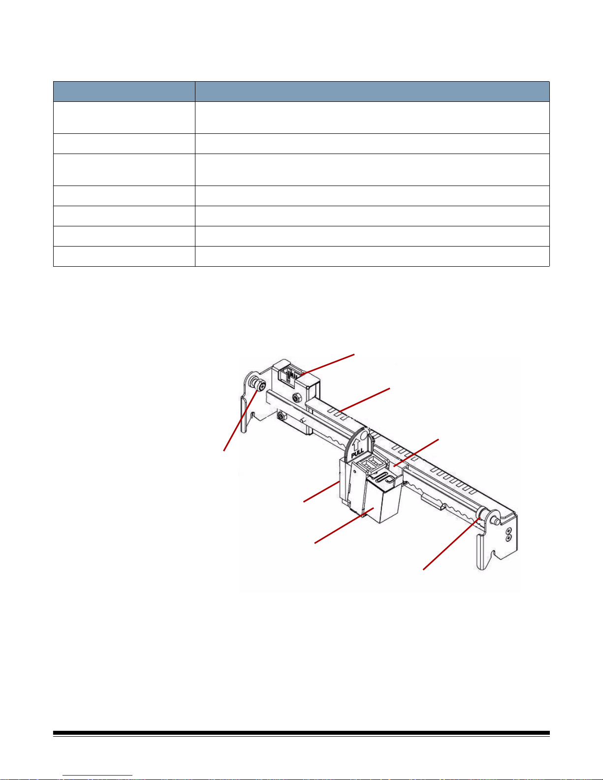
The imprinter is controlled from the scanning application installed on
Connector
Printing position scale
Carriage
Locating pin
Ink cartridge
Ink cartridge
holder
Thumbscrew
the host PC.
Item Specifications
Maximum number of characters
Print line(s) 1
Document paper type Low grade to regular bond documents can be used. Glossy paper should not
Print area 17 user-selectable horizontal print positions
Fonts User selectable: Standard/Wide; Standard/Normal; Large/Wide; Large/Normal
Character orientation 0, 90, 180, 270
Print resolution 96 dpi
Installing the front
page imprinter and
72 characters
be used, as the ink drying time is too long and smearing will result.
To ensure proper installation of the ink cartridge, install the imprinter
cartridge before installing the imprinter into the scanner. Be sure the ink
cartridge is properly seated.
ink cartridge
B-2 A-61662 October 2011
1. Remove the imprinter and ink cartridge from the box.
2. Remove the protective tape from the ink cartridge.
Page 77

3. Move the carriage to the center position.
Center position
Thumb screw
Ink
cartridge
Spring-loaded location pin
Imprinter door
4. Hold the ink cartridge holder with one hand and place the ink
cartridge (bottom end first) into the holder and snap it into place.
5. Turn off the scanner and power down the PC.
6. Remove the scanner exit tray.
7. Open the front page imprinter door.
8. Insert the imprinter’s spring-loaded locating pin into the correspond-
ing hole found in the scanner’s front page assembly (left side) with
the ink cartridge holder.
A-61662 October 2011 B-3
9. Hand-tighten the thumb screw located on the right side of the
imprinter into the corresponding hole found in the scanner’s front
page assembly.
Page 78

10. Connect the imprinter cable to the connector on the imprinter unit
noting the orientation of the key on the plug and the slot on t he connector.
11. Close the imprinter door.
12. Replace the exit tray.
13. Turn on the scanner and the PC.
14. Launch the Ngenuity Operator Utility and confirm the imprinter is
recognized.
NOTE: Do not leave the ink cartridge in the imprinter when not in use.
Removing the front
imprinter
1. Turn off the scanner.
2. Remove the exit tray.
3. Open the front page imprinter door.
4. Unplug the imprinter cable.
5. Unscrew the thumb screw located on the right side of the imprinter.
6. Pull the spring-loaded locating pin on the left side of the imprinter
unit away from the wall of the scanner.
7. Lift the imprinter up and out of the scanner.
8. Close the front page imprinter door, reinstall the exit tray and turn
on the scanner.
B-4 A-61662 October 2011
Page 79

Installing the back
Center position
page imprinter and
ink cartridge
To ensure proper installation of the ink cartridge, install the imprinter
cartridge before installing the imprinter into the scanner. Be sure the ink
cartridge is properly seated.
1. Remove the imprinter and ink cartridge from the box.
2. Remove the protective tape from the ink cartridge.
3. Move the carriage to the center position.
4. Hold the ink cartridge holder with one hand and place the ink
cartridge (bottom end first) into the holder and snap it into place.
5. Turn off the scanner and power down the PC.
6. Open the back page imprinter door located in the back of the scan-
ner.
7. Install the imprinter with the ink cartridge holder facing the bottom of
the scanner, inserting the spring-loaded locating pin into the corresponding hole found in the back page assembly.
8. Hand-tighten the thumb screw located on the left side of the
imprinter into the corresponding hole found in the scanner’s back
page assembly.
A-61662 October 2011 B-5
Page 80
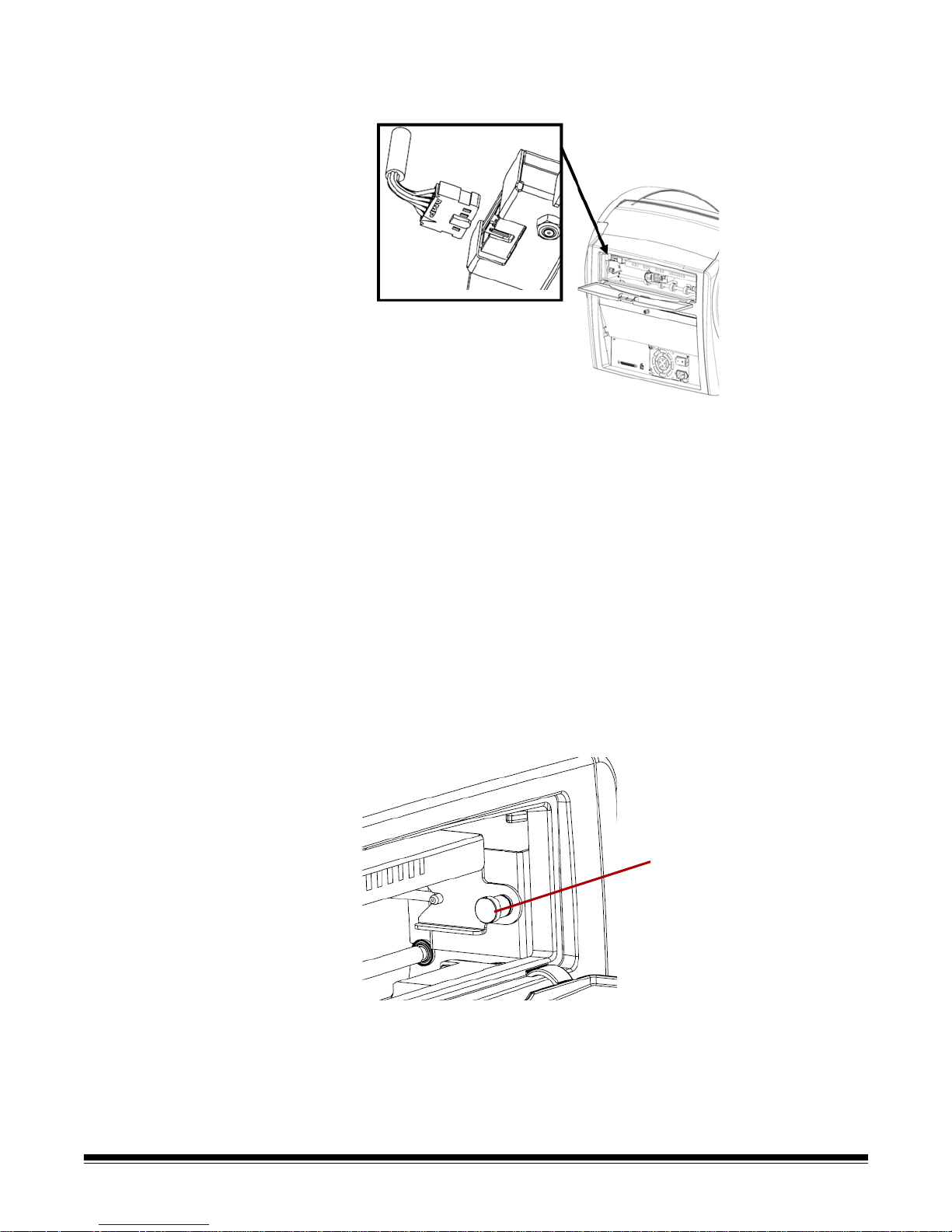
9. Connect the imprinter cable noting the orientation of the key on the
Locating pin
plug and the slot on the connector.
10. Close the back page imprinter door.
11. Turn on the scanner and the PC.
12. Launch the Ngenuity Operator Utility and confirm the imprinter is
recognized.
Removing the back
imprinter
NOTE: Do not leave the ink cartridge in the imprinter when not in use.
1. Turn off the scanner.
2. Open the back page imprinter door.
3. Unplug the imprinter cable.
4. Unscrew the thumb screw located on the left side of the imprinter.
5. Pull the spring-loaded locating pin away from the wall of the scan-
ner releasing the pin from the scanner’s back page assembly.
B-6 A-61662 October 2011
6. Pull the imprinter out of the scanner.
7. Close the back page imprinter door.
8. Turn on the scanner.
Page 81
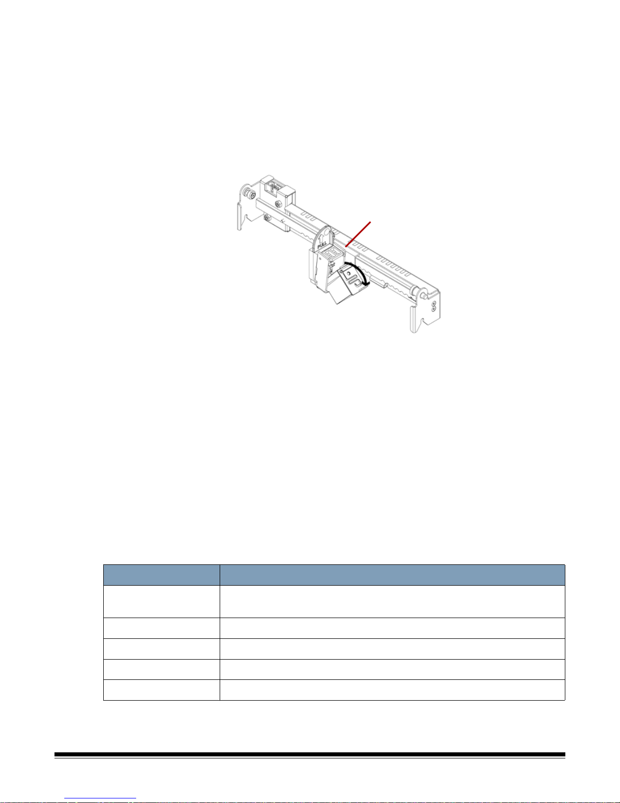
Maintenance
Center position
Replacing the ink cartridge 1. Turn off the scanner and power down the host PC.
2. Remove the front (or back) imprinter from the scanner. See the sec-
tions entitled, “Removing the front imprinter” or “Removing the back
imprinter” earlier in this appendix for instructions.
3. Remove the ink cartridge by grasping the ink cartridge holder and
pulling the tab on the ink cartridge out from the ink cartridge holder.
Ink cartridge specifications
Subject Specification
Ink Cartridge Life Approximately 4,000,000 characters (standard font)
Nozzles 12
Ink cartridge disposal: Consult the Hewlett-Packard website for
recycling printing supplies or disposing of the ink cartridges
according to local regulations.
4. Remove the protective tape from the new ink cartridge.
5. Move the ink cartridge carriage to the center position.
6. Hold the ink cartridge holder and place the ink cartridge (bottom
end first) into the holder and snap it into place.
7. Reinstall the imprinter into the scanner.
8. Turn on the scanner and the PC.
9. Launch the Ngenuity Operator Utility and confirm the imprinter is
recognized.
Approximately 2,000,000 characters (bold font)
Unusable Documents Plastic film or coated paper should not be used with the imprinter
Storage Envir onment Temperature: 32°F to 104°F (0°C to 40°C); Humidity: 10% to 80% RH
Operating Environment Temperature: 59°F to 86°F (15°C to 30°C); Humidity: 30% to 80% RH
A-61662 October 2011 B-7
Page 82

Cleaning the ink cartridge
print head
If the print head of the ink cartridge is dirty or the ink cartridge has not
been used for a long period of time, it may not print properly.
To clean the print head using the scanner, press the corresponding
Custom Function button (F1 or F2) on the control panel.
NOTE: You must assign the Clean Print Head function to one of the
Custom Function buttons (F1 or F2) using the Ngenuity
Operator Utility to be able to clean the print head using the
scanner. See the section entitled, “Settings button: Custom
functions” in Chapter 4.
1. In the NOU, go to the Settings screen, select Clean Print Head for
either F1 or F2 key assignment, and save to the scanner.
2. On the scanner, make sure print head(s) are positioned properly to
print at a desired print location.
3. Load one or more sheets of blank scrap paper that are wide enough
to pass under the current print head locations, and are at least 5
inches long.
4. Lower the skimmer and to allow the paper to load.
5. Press either the F1 or F2 (as assigned) key. A single sheet will be
fed and the print head cleaning pattern (a solid black stripe firing all
print head pins) will be printed on the page by each imprinter that is
installed.
6. Take the sheet from the exit tray and examine the printing. There
should be a relatively solid black stripe approximately 1.5 inches
long, with no voids or stripes. V oids or blank stripes indicate one or
more clogged ink jet nozzles.
7. Press either the F1 or F2 (as assigned) key to feed additional pages
until the printed black stripe is uniform and solid. This may take
several sheets.
8. If, after 6 to8 sheets, you cannot achieve a solid black stripe then
the print head should be removed from the imprinter and cleaned
manually . See the next section, “Additional p rint head cleaning” for a
more in-depth cleaning procedure.
9. Restore any previously set F key function via the NOU (if
necessary).
B-8 A-61662 October 2011
Page 83

Additional print head
cleaning
If cleaning the print head using the F1 key does not provide the desired
results, you can further clean the printer by following the steps below.
1. Turn off the scanner.
2. Remove the front (or back) imprinter unit from the scanner. See the
sections entitled, “Removing the front imprinter” or “Removing the
back imprinter” earlier in this chapter for instructions.
3. Remove the ink cartridge by grasping the ink cartridge holder and
pulling the tab on the ink cartridge out from the ink cartridge holder.
4. Dampen a clean, lint-free cloth with water.
5. Hold the cloth in contact with the nozzles on the ink cartridge for a
few seconds, then gently wipe the nozzle plate. Do not wipe the
electrical contact area.
6. If ink remains on the nozzle plate, wipe again with a dry, lint-free
cloth.
CAUTION: Do not use a roller cleaning pad to clean the print head.
Do not use any material that contains alcohol when
cleaning the print head.
Spit pad replacement The back page imprinter assembly contains a spit pad that is used to
absorb any excess ink from the front page imprinter during printing. The
spit pad is located underneath the back page assembly’s entry tray.
Over time the spit pad will become saturated and will need to be
replaced. The life expectancy of the spit pad is expected to last as long
or longer than the transport rollers. Contact Technical Support for spit
pad replacement.
A-61662 October 2011 B-9
Page 84

Using the imprinter Imprinter operation is controlled via the hardware and software.
Print positions
Carriage tab
Print position: hardware To print a string on the scanned document, adjust the position of the
print head carriage according to the size of the sheets that you want to
scan.
• Move the carriage to align the carriage tab with one of the marks that
appears on the scale on the imprinter. For the print string to appear
on the right side of the page, move the carriage to the right side of the
scale. For the imprint to appear on the left side of the p age, move the
carriage to the left side of the scale.
NOTE: If the carriage is not properly aligned with one of the marks on
the scale, the imprinter will not print on the document. The
following chart shows the position of the imprint in reference to
the document sheet being scanned.
B-10 A-61662 October 201 1
Make sure the document being scanned is the correct size for
the printing position or the imprinter will not print on the
document.
Page 85

Print position: software To set up the software for imprinting, access the Advanced Properties
screen which is accessible within Virtual ReScan® (VRS) Interactive
Viewer.
Scanning applications that use the VRS-based driver will display the
VRS icon in the Windows Taskbar on the host PC as soon as the scan
source is selected.
NOTE: For instructions on how to select the scan source (scanner),
see Chapter 4, Control Panel and Ngenuity Operator Utility.
1. Right-click on the VRS icon located in the Taskbar to launch the
Interactive Viewer.
2. Click Preview.
3. Within the Interactive Viewer, access the Advanced Properties
screen by clicking the Scanner Driver Settings icon (tools image).
4. In the Advanced Properties screen, click on the Imprinter menu item
to display the Imprinter controls.
A-61662 October 2011 B-11
5. Enable the imprinter you want to use: Front Page Prescan or Back
Page Postscan.
6. Click Text Controls.
NOTE: When VRS is not installed, imprinter controls can be found in
your Direct ISIS and TWAIN settings.
Page 86

The following options can be set via the Text Controls dialog box:
NOTE: Patch Code functionality is only available with the Kodak
Ngenuity 9150 Scanner.
Page Counter
Enable — click this checkbox to enable the Page Counters.
• Print Width — select to append zeros or spaces in front of the page
count or spaces at the end of the page count to retain a fixed length
for all digits that will appear in the text string. The default is leading
zeros.
For example, if the current counter value is 472, then the text string
for an 8-digit counter appears as follows:
With leading zeros: 00000472
With leading spaces: 472
With trailing spaces: 472
• Start At — when you start a new batch, this option allows you to set
the document count for the next document that will be scanned.
• Step Amount — select a value from the drop-down list to determine
how the automatic imprinter/annotation counter is incremented on
each page. The counter should be set based on the documents being
scanned, how the batches are organized, and specific user needs.
Increment amounts of 0 - 9.
NOTE:When the counter value exceeds the number of digits
selected, the counter value resets to 0, depending on the
increment amount.
B-12 A-61662 October 201 1
Page 87

• Digits — select a value from the drop-down list to specify the page
counter length, which should take into consideration any leading
zeros or leading or trailing spaces appended to the page count in the
Print Width drop-down list. You can specify from 1 to 9; default is 5.
Font Height and Font Width — select whether you want imprinted text
to print normally or in larger and/or wider characters on a document.
Selecting Large prints taller characters; selecting Wide prints wider
characters. The default print size is Normal.
The font size selections only control the imprinted text; the font used for
annotation is fixed and cannot be changed.
NOTE: Selecting Large or Wide may change the length of text strings,
causing the text to print off the end of the document. By de fault,
the scanner prints standard, Latin font characters.
Text Orientation — select the orientation (rotation) for the imprinted
and/or annotated text string. A preview of how the text will be oriented
at 0 (default), 90, 180 and 270 degrees will be displayed to the right of
the selected orientation.
Insert Dynamic Content — allows you to select a pre-formatted date
and time or special content code to be inserted into the text string. The
code is replaced by actual data when a document is scanned.
NOTE: Counter digit and Dynamic content information becomes part of
the imprinting or annotation string in the "Print String Definition"
text box and Actual Printed Example field.
• Date and Time: select date and time format codes to include in the
text string from the Date and Time drop-down list. These codes are
replaced with actual dates and times by the scanner when the
document is scanned. The date and time format choices as well as
the pre-formatted date and time code are shown in the table below.
Date & Time
format
HH:MM %T0 03:15 MM/DD/YYYY %D3 07/05/2009
HH:MM:SS %T1 03:15:23 DD/MM/YY %D4 05/07/09
HH:MM
AM/PM
HH:MM:SS
AM/PM
YY/MM/DD %D0 09/07/05 MM %D7 07
Date & Time
code
%T2 03:15 PM DD/MM/YYYY %D5 05/07/2009
%T3 03:15:23
Example
PM
Date & Time
format
DD %D6 05
Date & Time
code
Example
YYYY/MM/DD %D1 2009/07/05 YY %D8 09
MM/DD/YY %D2 07/05/09 YYYY %D9 2009
A-61662 October 2011 B-13
NOTE: The scanner's time and date is seeded from the host PC's
clock when the connection to the scanner is established.
Page 88

Special Content — select special content format codes to include in
the text string from the drop-down list. These codes are replaced with
actual symbols or text by the scanner when the document is scanned.
The special content format choices and pre-formatted special content
codes are shown in the table below.
Special Content Code Example
Euro Symbol %A0128 €
Yen Symbol %A0165 ¥
Scanner ID %S0 12345678
Annotation Position — allows you to specify the horizont al location for
annotating.
• Offset from Left: specify the distance of an annotation string from
the left edge of a page. The minimum value is 0 (default) and the
maximum value is dependent on the resulting image size. You must
enter whole numbers for pixels and millimeters, but you can enter
decimal numbers in 0.1-inch increments for inches. This option is
only available if Front and/or Back Annotation is selected.
• Front Annotation/Back Annotation: annotation can be performed
on the front, back, or both sides of a document and is enabled using
the Front Annotation and Back Annotation check boxes.
To specify the position of annotation text on a document:
1. In the Units group, select a unit of measurement for the offset.
2. In the Offset from Top text box, specify the distance from the top
edge of the page the annotation string should appear. (This value
also controls the mechanical imprinter text offset.)
3. Select where you want the annotation: Front, Back or Front and
Back.
4. In the Offset from Left text box, specify the distance from the left
edge of the page the annotation string should appear.
5. Click OK when finished.
NOTE: Because this measurement affects where the annotation is
added to the actual image, be sure to select an offset
measurement that remains within the length and width of the
image.
Units — use the options in the Units group to specify text positioning
values in inches, millimeters, or pixels (dpi dependent). The default unit
of measurement is inches.
B-14 A-61662 October 201 1
Imprinter/Annotation Position — the Imprinter / Annotation Position
settings are all offsets from the top in this frame. The same Offset from
the top value applies to both the physical imprinter and the electronic
annotation.
Page 89

• Offset from Top — specify the distance of the imprinter string from
the top of each page. The default and minimum value is 0.5; the
maximum value is 25.5 inches. You must enter whole numbers for
pixels and millimeters, but you can enter decimal numbers in 0.1-inch
increments for inches.
NOTE:The horizontal location for imprinting must be manually set
inside the scanner.
Print String Definition, Maximum String Length and Remaining
Count — use the Print String Definition text box to set up and/or modify
the text string that you want imprinted or annotated on a document. You
can provide information for the text string by typing a text string in the
text box or inserting pre-formatted information from the Page Counter
and Insert Dynamic Content drop-down lists. You cannot insert text
using the cut and paste function.
You can see how the text string will appear as imprinted or annotated
text in the Actual Printed Example field.
Exceeding the maximum string length of 72 results in the string being
truncated to the maximum length. Because the imprinter/annotation
string is made up of text, a page counter, and dynamic content,
consider their combined length and the character placeholders
remaining (shown in the Remaining Count box) when setting the string
length.
Actual Printed Example — the text displayed under Actual Printed
Example shows how the current imprinting or annotation text will look
with any optional date and time stamp, special content, or page counter
expanded. When a date and time format is specified, the current date
and time are applied.
A-61662 October 2011 B-15
Page 90

Patch Code options Imprint Patch Code Sheets — enable this option if you want to print
on patch code sheets and count them with the index counter. This
setting only applies to patch types 1, 2, 3, 5, and 6. Patch types 4, 7, 8
and 9 will not get printed or counted even with this checkbox selected.
The Increment on Patch Code and Reset on Patch Code options are
only for the Kodak Ngenuity 9150 Scanner.
Set these options if you
want to use patch sheets within a batch to control printer index values.
A set of patch codes can be found on the Installation CD or on the
website at www.kodak.com/go/scanners; under Support>User
Manuals.
Increment on Patch Code
Enable — select this checkbox to increment the index count value
when the specified patch code is detected instead of incrementing the
index count on each page.
Patch Code: select the Patch Code Type that will increment the index
counter when Increment on Patch is enabled.
Reset on Patch Code
Enable — select this checkbox to reset the index count value to the
Reset Count value when the specified patch code is detected.
Reset Count: the index count value that takes effect when the Reset
Patch Code is detected when Reset on Patch is enabled.
Patch Code: select the Patch Code Type that will reset the index
counter when Reset on Patch Code is enabled.
Changes to the index count value due to Increment on Patch and Reset
on Patch will take effect regardless of whether Imprint Patch Code
Sheets is selected. For more information and samples of Patch Codes,
see Appendix E, Patch Code Information.
B-16 A-61662 October 201 1
Page 91

Appendix C Installing and Using the Optional Straight Pass-
Through Adapter
Contents Installing the straight pass-through adapter................................... C-1
Using the straight pass-through adapter........................................ C-2
The straight pass-through adapter allows you to output fragile or thick
documents through the straight pass-through door thus shortening the
paper path and minimizing document jams. The documents will be
stacked in the reverse order from the feeding order.
Installing the straight passthrough adapter
1. Open the straight pass-through door.
2. Insert the straight pass-through adapter into the scanner.
A-61662 October 2011 C-1
3. Push the straight pass-through adapter down and snap it into place.
Once the straight pass-through adapter is inst alled, you do not have
to uninstall it when it is not in use.
Page 92

Using the straight passthrough adapter
NOTE:If you are scanning exception documents, it is not necessary to
have the exit tray attached. Use the exit tray when you are
scanning many documents.
1. Remove the exit tray from the front of the scanner.
2. Install the exit tray matching the tabs on the exit tray with the slots
on the straight pass-through adapter and be sure that it is securely
in place.
3. Adjust the side guides and the end stop on the exit tray as desired
to meet your scanning needs.
NOTES:
• When you are not using the straight pass-through door to output your
documents, remove the exit tray, put it back in the front of the
scanner and close the straight pass-through door.
• Be sure the wire stand underneath the exit tray is folded down so it
rests evenly on the tabletop.
• When straight pass-through door is open, the Back Doo r st atus ligh t
on the control panel will be lit.
C-2 A-61662 October 2011
Page 93

Appendix D Glossary
Control panel — interface located on the front of the scanner that is
used to perform basic scanning functions and to signal scanner status
through the use of LEDs, pictograms and text.
DPI (dots per inch) — a measurement of the ability of a scanner to
reproduce small objects. The higher the dpi, the smaller the object the
scanner can reproduce. Also known as resolution.
Host PC — computer used to communicate with the scanner in order to
scan documents.
LED (Light Emitting Diode) — type of light source used in the scanner,
both for image capture while scanning and illuminating indicators found
on the control panel.
Multifeed (MF) — occurs when more than one document is fed through
the feeder at one time.
Optics — refers to the following scanner components: imaging guides,
camera glass covers and sensors. This term does not include LEDs.
Paper jam — refers to a single document that fails to pass through the
scanner transport and exit into the exit tray.
Scan source — the scanner selected for use through the scanning
application on the host PC.
Ngenuity Operator Utility (NOU) — the software that resides on the
host PC. It provides and monitors scanner connectivity, scanner status
and alerts. Allows you to set some of the scanner’s configuration
parameters.
Straight pass-through — alternative transport path that allows
scanning of thick card stock, ID cards, etc. Documents enter the
transport from the feeder table and exit out the back of the scanner.
USB (Universal Serial Bus) — a data transmission system that
operates between the scanner and the host computer system.
VRS (VirtualReScan) — VRS is an electronic check-point for scanned
images. As images pass through the scanner, VRS performs a multipoint inspection of each document. VRS automatically checks and
adjusts for alignment (skew), brightness, contrast and image clarity.
VRS Interactive Viewer — VRS-enabled control window where you
can access advanced features of the scanner.
A-61662 October 2011 D-1
Page 94

Appendix E Patch Code Information
This appendix provides additional information for patch codes
supported by Kodak Ngenuity 9000 Series Scanners.
Kodak Ngenuity Scanners include two hardware-based Patch Reade rs.
The Patch Reader recognizes patches with bars that are parallel to the
lead edge of the document. All Kodak Ngenuity Scanners support p atch
reading for color toggle patch processing. Only the Kodak Ngenuity
9150 Scanner supports Printer Counter Increment and Resetting
through Patch. The Kodak Ngenuity 9150 Scanner does not support full
image addressing or batching.
The following additional patches for the Kodak Ngenuity Series
Scanners have the same element specifications as the Patch Codes
described in Kodak publication, A-61599, “Patch Code Information for
Kodak Scanners”.
The wide bars should be 0.20 inches (5 mm) wide plus 0.01 inches
(0.25 mm). The narrow bars and spaces should be 0.08 inches (2.03
mm) wide plus 0.01 inches (0.25 mm). The maximum width of the patch
code is 0.80 inches (20 mm) plus 0.01 inches (0.25 mm). The minimum
overall length of the patch bars is 2 inches (50 mm).
For vertical placement, the patch cannot start before 0.25 inches from
the leading edge of the page and the bottom of the patch pattern must
finish before 3.75 inches from the leading edge.
The only exception to this is when Increment on Patch or Reset on
Patch is checked; the patches must occur in the region from 0.25
inches to 1.70 inches from the leading edge.
NOTE:Only patches on the top side of the document will be read.
A-61662 October 2011 E-1
Page 95
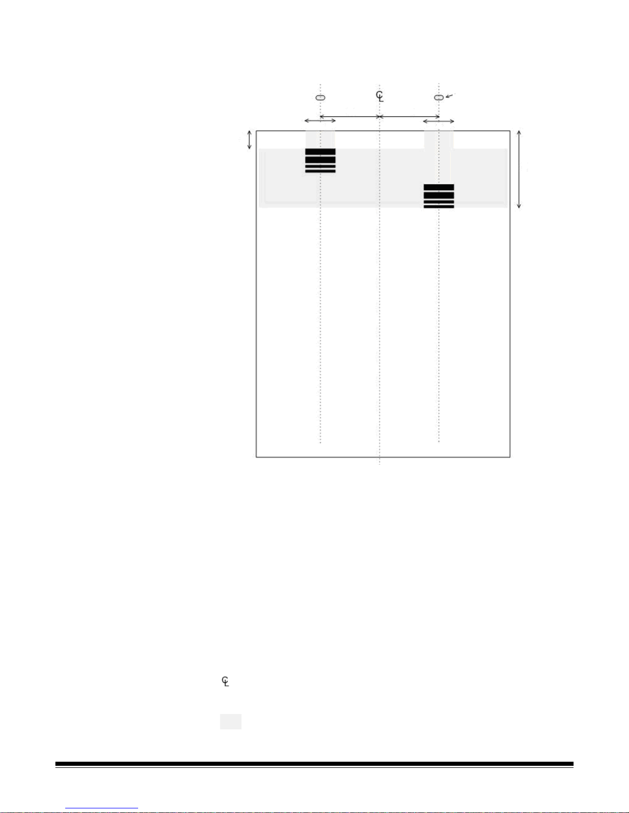
The horizontal placement must result in the patch pattern crossing the
A
C
C
B
DD
Patch sensors
scanner’s sensor locations. Refer to the following illustration.
• Patch code bar dimensions and optical properties should conform to
the Kodak specifications outlined in Kodak Publication, A-61599.
• Patch codes must be printed parallel to the document lead edge.
KEY:
A — the minimum distance from the document edge to the start of the patch
code = 0.25 in.
B — the maximum distance from the document edge to the end of the patch
code = 1.70 in.
C — the recommended minimum width of th e patch code centered around the
sensor location = 1.0 in.
D — the distance from the transport/feeder center to the p atch code sensor =
2.0 in.
— center line of the scanner document feeder with the side guides
centered.
— allowable vertical region for the printed patch code.
The entire region above the patch code must be free of printing.
E2 A-61662 October 2011
Page 96

Key for Graphical Pattern Description:
W Wide Bar
n Narrow Bar
The graphical pattern read from left to right indicates the time sequence
of patch pattern bars (first to last).
Numeric code Graphical Pattern Comment
0 No code detected
1 WWnn Kodak Patch Code #1
2WnnWKodak Patch Code #2
3WnWnKodak Patch Code #3
4nWWnKodak Patch Code #4 (Kodak Toggle Patch)
5nWnWKodak Patch Code #5 (Kodak Transfer Patch)
6nnWWKodak Patch Code #6
7WWWnKodak Ngenuity 9150 only - Code #7 - Scan in Bitonal
8WWnWKodak Ngenuity 9150 only - Code #8 - Scan in Color
9WnWWKodak Ngenuity 9150 only - Code #9 - Scan in Gray
10 nWWW Kodak Ngenuity 9150 only - Code #10 - Future use
11 nnnW Kodak Ngenuity 9150 only - Code #11 - Future use
12 nnWn Kodak Ngenuity 9150 only - Code #12 - Future use
13 nWnn Kodak Ngenuity 9150 only - Code #13 - Future use
14 Wnnn Kodak Ngenuity 9150 only - Code #14 - Future use
NOTE:The following patch codes are not to specification. Use the patch
sheets included on the CD for specifications.
A-61662 October 2011 E-3
Page 97

Patch codes
Patch 7 Patch 8
Patch 9
Patch 11
Patch 13
Patch 10
Patch 12
Patch 14
E4 A-61662 October 2011
Page 98

 Loading...