

Page 1
Operator Manual S008769 Rev A
S00XXXX Rev A
Page 2

Europe Asia
The Bowe House Room 1203, Tower B, COFCO Plaza
The Sterling Centre No. 8 JianGuoMenNei Ave, Dong Cheng Dist.
Bracknell, Berkshire RG12 2PW Beijing, 100005
England China (PRC)
Sales: +44-1344-462-103 Phone: +86-10-65256601
Fax: +44-1344-462-101 Fax: +86-10-65256601
Contact Information
United States
©BÖWE BELL + HOWELL
760 South Wolf Road
Wheeling, Illinois 60090
Corporate: 1-847-675-7600
Sales: 1-800-SCAN-494
Scanner Help Desk: 1-800-SCAN-495
1-585-781-8616
TTY Line: 1-847-423-3032
Fax: 1-847-423-3047
On the Web www.bbhscanners.com
NOTICE
The instructions and descriptions contained in this document were accurate at the time of publishing, however, succeeding products and documents are subject to change without notice. Therefore, BÖWE BELL + HOWELL assumes no liability for damages incurred directly or indirectly from
errors, omissions, or discrepancies between the product and this document.
The information given in this Manual is subject to change without notice. Please go to
www.bbhscanners.com
©2009 BÖWE BELL + HOWELL. All Rights Reserved. All intellectual property rights remain the
property of BÖWE BELL + HOWELL. No part of this publication may be reproduced, distributed,
modified, displayed, transmitted, stored in a retrieval system, or translated into any human or
computer language, in any form or by any means, electronic, mechanical, magnetic, optical,
Ngenuity Operator Manual
chemical, manual, or otherwise, without the prior written permission of the copyright owner,
BÖWE BELL + HOWELL, 760 South Wolf Road, Wheeling, Illinois 60090.
ii S008769 Rev A
to download the most current Manual.
Page 3

Release Notes
As future revisions of this manual are released, this section will contain a list of any changes that
were made for that specific revision of the manual. The list will contain a brief description of each
change and a link to the location in the manual where the change occurs.
Item Status Location in Manual Detail
Release Notes
Ngenuity Operator
Manual
New Rev A
S008769 Rev A iii
Page 4

Ngenuity Operator Manual
iv S008769 Rev A
Page 5

Table of Contents
Contact Information ...............................................................................ii
Release Notes ........................................................................................iii
Table of Contents ...................................................................................v
Preface ....................................................................................................ix
THANK YOU . . . . . . . . . . . . . . . . . . . . . . . . . . . . . . . . . . . . . . . . . . . . . . . . .IX
REGISTRATION . . . . . . . . . . . . . . . . . . . . . . . . . . . . . . . . . . . . . . . . . . . . . .IX
ABOUT NGENUITY . . . . . . . . . . . . . . . . . . . . . . . . . . . . . . . . . . . . . . . . . . . . X
COMPLIANCES . . . . . . . . . . . . . . . . . . . . . . . . . . . . . . . . . . . . . . . . . . . . . . . X
TRADEMARK ACKNOWLEDGMENTS . . . . . . . . . . . . . . . . . . . . . . . . . . . . . . . .XI
SYMBOLS YOU SHOULD KNOW . . . . . . . . . . . . . . . . . . . . . . . . . . . . . . . . . .XI
Getting Started .......................................................................................1
1.1 How this Manual is Organized . . . . . . . . . . . . . . . . . . . . . . . . . . . . . . 1
Table of Contents
1.2 Safety Guidelines . . . . . . . . . . . . . . . . . . . . . . . . . . . . . . . . . . . . . . . 1
1.3 Operating Environment . . . . . . . . . . . . . . . . . . . . . . . . . . . . . . . . . . . 3
1.4 External Component Identification . . . . . . . . . . . . . . . . . . . . . . . . . . . 5
1.4.1 Scanner Front . . . . . . . . . . . . . . . . . . . . . . . . . . . . . . . . . . . . . . . . .6
1.4.2 Scanner Back . . . . . . . . . . . . . . . . . . . . . . . . . . . . . . . . . . . . . . . .11
1.5 Unpacking/Repacking . . . . . . . . . . . . . . . . . . . . . . . . . . . . . . . . . . . 12
1.5.1 What You Should Have Received . . . . . . . . . . . . . . . . . . . . . . . . .13
1.6 Specifications . . . . . . . . . . . . . . . . . . . . . . . . . . . . . . . . . . . . . . . . . 13
1.6.1 Scanner . . . . . . . . . . . . . . . . . . . . . . . . . . . . . . . . . . . . . . . . . . . . .14
1.6.2 Software . . . . . . . . . . . . . . . . . . . . . . . . . . . . . . . . . . . . . . . . . . . .15
1.7 Installation . . . . . . . . . . . . . . . . . . . . . . . . . . . . . . . . . . . . . . . . . . . . 15
Operating Your Scanner ......................................................................17
2.1 Control Panel . . . . . . . . . . . . . . . . . . . . . . . . . . . . . . . . . . . . . . . . . . 17
2.1.1 Status . . . . . . . . . . . . . . . . . . . . . . . . . . . . . . . . . . . . . . . . . . . . . .18
2.1.1.1 Power Mode LED . . . . . . . . . . . . . . . . . . . . . . . . . . . . . . . . . . 18
2.1.1.2 Back Door LED . . . . . . . . . . . . . . . . . . . . . . . . . . . . . . . . . . . . 19
2.1.1.3 Maintenance LED . . . . . . . . . . . . . . . . . . . . . . . . . . . . . . . . . . 19
2.1.1.4 Manual Feed LED . . . . . . . . . . . . . . . . . . . . . . . . . . . . . . . . . . 20
2.1.1.5 Feed Modes . . . . . . . . . . . . . . . . . . . . . . . . . . . . . . . . . . . . . . 21
ADF M
M
A
T
ODE . . . . . . . . . . . . . . . . . . . . . . . . . . . . . . . . . . . . . . . . 21
ANUAL MODE . . . . . . . . . . . . . . . . . . . . . . . . . . . . . . . . . . . . . 21
SSISTED MANUAL MODE . . . . . . . . . . . . . . . . . . . . . . . . . . . . . 23
EST FEED MODE . . . . . . . . . . . . . . . . . . . . . . . . . . . . . . . . . . . 23
S008769 Rev A v
Page 6

2.1.2 Feeder Table . . . . . . . . . . . . . . . . . . . . . . . . . . . . . . . . . . . . . . . . 23
2.1.3 Custom Functions . . . . . . . . . . . . . . . . . . . . . . . . . . . . . . . . . . . . . 24
2.1.4 Scan Monitor . . . . . . . . . . . . . . . . . . . . . . . . . . . . . . . . . . . . . . . . . 24
2.1.4.1 Error LED . . . . . . . . . . . . . . . . . . . . . . . . . . . . . . . . . . . . . . . . 24
2.1.4.2 Cover LED . . . . . . . . . . . . . . . . . . . . . . . . . . . . . . . . . . . . . . . . 25
2.1.4.3 Paper Jam LED . . . . . . . . . . . . . . . . . . . . . . . . . . . . . . . . . . . . 25
2.1.4.4 Misfeed LED . . . . . . . . . . . . . . . . . . . . . . . . . . . . . . . . . . . . . . 25
2.1.4.5 Multifeed LED & MF Ignore Pushbutton . . . . . . . . . . . . . . . . . 26
VRS M
P
ULTIFEED IGNORE . . . . . . . . . . . . . . . . . . . . . . . . . . . . . . 26
REEMPTIVE MULTIFEED IGNORE . . . . . . . . . . . . . . . . . . . . . . . . 27
2.1.1 Batch Control . . . . . . . . . . . . . . . . . . . . . . . . . . . . . . . . . . . . . . . . 27
2.1.5.1 Ready LED . . . . . . . . . . . . . . . . . . . . . . . . . . . . . . . . . . . . . . . 27
2.1.5.2 Clear/Restart Pushbutton . . . . . . . . . . . . . . . . . . . . . . . . . . . . 28
2.1.5.3 Pause/Stop Pushbutton . . . . . . . . . . . . . . . . . . . . . . . . . . . . . . 28
2.2 Ngenuity Operator Utility . . . . . . . . . . . . . . . . . . . . . . . . . . . . . . . . . 29
2.2.1 Menu Bar . . . . . . . . . . . . . . . . . . . . . . . . . . . . . . . . . . . . . . . . . . . 30
2.2.1.1 Menu - Scanner . . . . . . . . . . . . . . . . . . . . . . . . . . . . . . . . . . . . 31
D
ETAILS . . . . . . . . . . . . . . . . . . . . . . . . . . . . . . . . . . . . . . . . . . 31
U
PDATE FIRMWARE . . . . . . . . . . . . . . . . . . . . . . . . . . . . . . . . . . 32
E
XIT . . . . . . . . . . . . . . . . . . . . . . . . . . . . . . . . . . . . . . . . . . . . . 32
2.2.1.2 Menu - Language . . . . . . . . . . . . . . . . . . . . . . . . . . . . . . . . . . . 32
2.2.1.3 Menu - Help . . . . . . . . . . . . . . . . . . . . . . . . . . . . . . . . . . . . . . . 32
P
ROGRAM HELP . . . . . . . . . . . . . . . . . . . . . . . . . . . . . . . . . . . . 33
V
IEW OPERATOR MANUAL . . . . . . . . . . . . . . . . . . . . . . . . . . . . . 33
P
RODUCT SUPPORT . . . . . . . . . . . . . . . . . . . . . . . . . . . . . . . . . 33
A
BOUT SCANNER OPERATOR UTILITY . . . . . . . . . . . . . . . . . . . . . 33
2.2.2 Home Screen . . . . . . . . . . . . . . . . . . . . . . . . . . . . . . . . . . . . . . . . 34
2.2.2.1 Scanner Model . . . . . . . . . . . . . . . . . . . . . . . . . . . . . . . . . . . . . 34
2.2.2.2 Scanner Self Test . . . . . . . . . . . . . . . . . . . . . . . . . . . . . . . . . . 34
2.2.2.3 Maintenance Monitor . . . . . . . . . . . . . . . . . . . . . . . . . . . . . . . . 35
2.2.3 Settings Screen . . . . . . . . . . . . . . . . . . . . . . . . . . . . . . . . . . . . . . 37
2.2.3.1 Sleep Timeout . . . . . . . . . . . . . . . . . . . . . . . . . . . . . . . . . . . . . 37
2.2.3.2 Multifeed . . . . . . . . . . . . . . . . . . . . . . . . . . . . . . . . . . . . . . . . . 37
2.2.3.3 Custom Functions . . . . . . . . . . . . . . . . . . . . . . . . . . . . . . . . . . 38
2.2.3.4 Audio . . . . . . . . . . . . . . . . . . . . . . . . . . . . . . . . . . . . . . . . . . . . 38
2.2.3.5 Advanced Settings Button . . . . . . . . . . . . . . . . . . . . . . . . . . . . 39
B
ORDER ADJUST . . . . . . . . . . . . . . . . . . . . . . . . . . . . . . . . . . . . 39
2.2.3.6 Save and Restore Buttons . . . . . . . . . . . . . . . . . . . . . . . . . . . . 39
2.2.4 Maintenance Screen . . . . . . . . . . . . . . . . . . . . . . . . . . . . . . . . . . . 40
2.2.4.1 Scanner Stats . . . . . . . . . . . . . . . . . . . . . . . . . . . . . . . . . . . . . 40
Ngenuity Operator Manual
2.2.4.2 Configure Maintenance Reminders . . . . . . . . . . . . . . . . . . . . . 41
Advanced Features .............................................................................. 43
3.1 Accessing Advanced Features . . . . . . . . . . . . . . . . . . . . . . . . . . . . 43
3.2.1 Multifeed Screen . . . . . . . . . . . . . . . . . . . . . . . . . . . . . . . . . . . . . . 46
vi S008769 Rev A
Page 7

3.2.1.1 Multifeed Mode . . . . . . . . . . . . . . . . . . . . . . . . . . . . . . . . . . . . 46
3.2.1.2 Enable Sensors . . . . . . . . . . . . . . . . . . . . . . . . . . . . . . . . . . . . 47
3.2.1.3 Ignore by Size . . . . . . . . . . . . . . . . . . . . . . . . . . . . . . . . . . . . . 47
3.2.2 Document Setup Screen . . . . . . . . . . . . . . . . . . . . . . . . . . . . . . . .48
3.2.2.1 Document Types . . . . . . . . . . . . . . . . . . . . . . . . . . . . . . . . . . . 48
3.2.2.2 Allow Large Skew . . . . . . . . . . . . . . . . . . . . . . . . . . . . . . . . . . 48
3.2.2.3 Very Long Document . . . . . . . . . . . . . . . . . . . . . . . . . . . . . . . . 48
3.2.2.4 Ignore Holes/Ragged Edges . . . . . . . . . . . . . . . . . . . . . . . . . . 49
3.2.2.5 Front/Back Negative Image Enable . . . . . . . . . . . . . . . . . . . . . 50
3.2.3 Advanced Color Screen . . . . . . . . . . . . . . . . . . . . . . . . . . . . . . . .50
Scanner Options ...................................................................................53
4.1 Imprinter . . . . . . . . . . . . . . . . . . . . . . . . . . . . . . . . . . . . . . . . . . . . . 53
4.2 SCSI Connection . . . . . . . . . . . . . . . . . . . . . . . . . . . . . . . . . . . . . . . 53
4.2.1 Installation . . . . . . . . . . . . . . . . . . . . . . . . . . . . . . . . . . . . . . . . . . .54
4.2.2 Troubleshooting . . . . . . . . . . . . . . . . . . . . . . . . . . . . . . . . . . . . . . .55
Maintenance ..........................................................................................57
5.1 Version Numbers . . . . . . . . . . . . . . . . . . . . . . . . . . . . . . . . . . . . . . . 57
5.1.1 Update Firmware . . . . . . . . . . . . . . . . . . . . . . . . . . . . . . . . . . . . . .57
5.2 Maintenance Schedule . . . . . . . . . . . . . . . . . . . . . . . . . . . . . . . . . . 57
5.2.1 Items Needed . . . . . . . . . . . . . . . . . . . . . . . . . . . . . . . . . . . . . . . .59
5.3 Maintenance Procedures . . . . . . . . . . . . . . . . . . . . . . . . . . . . . . . . . 59
5.3.1 Feed Rollers . . . . . . . . . . . . . . . . . . . . . . . . . . . . . . . . . . . . . . . . .60
5.3.1.1 Skimmer Rollers . . . . . . . . . . . . . . . . . . . . . . . . . . . . . . . . . . . 60
C
LEANING THE SKIMMER ROLLERS . . . . . . . . . . . . . . . . . . . . . . 61
R
EPLACING TIRES . . . . . . . . . . . . . . . . . . . . . . . . . . . . . . . . . . . 63
5.3.1.2 Separator Roller . . . . . . . . . . . . . . . . . . . . . . . . . . . . . . . . . . . 65
C
LEANING THE SEPARATOR ROLLER . . . . . . . . . . . . . . . . . . . . . 66
R
EPLACING THE SEPARATOR ROLLER . . . . . . . . . . . . . . . . . . . . 67
5.3.2 Optics . . . . . . . . . . . . . . . . . . . . . . . . . . . . . . . . . . . . . . . . . . . . . .68
5.3.2.1 Glass Flats . . . . . . . . . . . . . . . . . . . . . . . . . . . . . . . . . . . . . . . . 68
C
LEANING GLASS FLATS . . . . . . . . . . . . . . . . . . . . . . . . . . . . . . 69
R
EPLACING GLASS FLATS . . . . . . . . . . . . . . . . . . . . . . . . . . . . . 71
5.3.3.2 Cameras’ Glass Covers . . . . . . . . . . . . . . . . . . . . . . . . . . . . . . 72
C
LEANING THE CAMERAS’ GLASS COVERS . . . . . . . . . . . . . . . . . 73
5.3.3.3 Cleaning the Sensors . . . . . . . . . . . . . . . . . . . . . . . . . . . . . . . 74
C
LEANING THE FEEDER SENSOR . . . . . . . . . . . . . . . . . . . . . . . . 75
C
LEANING TRANSPORT SENSORS . . . . . . . . . . . . . . . . . . . . . . . 76
5.3.4 Camera Calibration . . . . . . . . . . . . . . . . . . . . . . . . . . . . . . . . . . . .80
5.3.5 Cleaning the Transport . . . . . . . . . . . . . . . . . . . . . . . . . . . . . . . . .82
5.3.6 Lamps (LEDs) . . . . . . . . . . . . . . . . . . . . . . . . . . . . . . . . . . . . . . . .83
5.3.7 Feeder Cork Pad Replacement . . . . . . . . . . . . . . . . . . . . . . . . . . .83
Table of Contents
Troubleshooting ...................................................................................85
S008769 Rev A vii
Page 8

6.1 Preliminary Troubleshooting Procedures . . . . . . . . . . . . . . . . . . . . . 85
Glossary ................................................................................................ 89
Ngenuity Operator Manual
viii S008769 Rev A
Page 9

Preface
Thank You
Thank you for purchasing a BÖWE BELL + HOWELL (BBH) Ngenuity scanner!
The Ngenuity bundle consists of everything you need to connect and operate the scanner. This
includes the scanner itself, a USB™ 2.0 cable and the operating software, which includes
Ngenuity’s OEM version of VirtualReScan
The model number of your Ngenuity scanner can be identified within the Home Screen of the
Ngenuity Operator Utility or NOU (see ”2.2
”2.2.2.1
Ngenuity scanners are designed to be reliable, easy to connect, maintain and service. They are
also designed to handle a variety of document sizes and types.
Please take a few minutes to review this Operator manual. It contains the detailed information
you need to get the most out of your Ngenuity scanner.
This manual is formatted for 2-sided printing.
Scanner Model” on page 34).
®
(VRS), 4.2 or newer.
Ngenuity Operator Utility” on page 29, specifically
Preface
Registration
Please register your new, Ngenuity scanner! Registering serves as a verification of ownership
and confirms your right to protection under the terms and conditions of your warranty.
Registration also helps us serve you better if you need to call BBH about this product. Visit the
warranty registration page on our web site (www.bbhscanners.com/support/current_products/
ngenuity/warranty/index.html) or complete and return the warranty registration card that shipped
with the scanner.
S008769 Rev A ix
Page 10

About Ngenuity
Your Ngenuity scanner offers the following:
• Integrated feeding system - Seamlessly scans a wider range of documents from rice paper to
plastic cards; from documents smaller than business cards to documents up to 200 M in
length
• Straight Pass-Through paper path
• 700 page automatic document feeder
• 600 dpi camera capture and output
• Scanning speeds of up to 150 ppm at 200 dpi in color, grayscale, and bitonal
• Ngenuity Operator Utility (NOU)
• USB v2.0 interface
• LED illumination
• Quiet operation
Compliances
EMC Statements
(For United States only)
This equipment has been tested and found to comply with the limits for a Class A digital
device, pursuant to part 15 of the FCC Rules. These limits are designed to provide reasonable
protection against harmful interference when the equipment is operated in a commercial environment. This equipment generates, uses and can radiate radio frequency energy and, if not
installed and used in accordance with the instruction manual, may cause harmful interference
to radio communications. Operation of this equipment in a residential area is likely to cause
harmful interference in which case the user will be required to correct the interference at his
own expense.
FCC Warning: To assure continued FCC compliance, the user must use only shielded interface cable and the provided power supply cord. Also, any unauthorized changes or modifications to this equipment would void the user’s authority to operate this device.
(For Canada)
Ngenuity Operator Manual
THIS CLASS A DIGITAL APPARATUS COMPLIES WITH CANADIAN ICES-003.
CET APPAREIL NUMÉRIQUE DE LA CLASSE A EST CONFORME Á LA NORME NMB-003
DU CANADA.
x S008769 Rev A
Page 11

(For European Union)
WARNING: This is a Class A product. In a domestic environment this product may cause
radio interference in which case the user may be required to take adequate measures.
Trademark Acknowledgments
• BÖWE BELL + HOWELL, SharpShooter, Ngenuity and the Böwe Bell + Howell logo are
trademarks or registered trademarks of BBH, Inc.
®
• Windows
• Windows
•Microsoft
Corporation in the United States and/or other countries
• AMD Athlon™ is a trademark or registered trademark of AMD
• VirtualReScan
Products
•ISIS
•TWAIN
• Adobe
• Intel
countries
• Pentium
countries
2000 is Microsoft® Windows® 2000 operating system
®
XP is Microsoft® Windows® XP operating system
®
and Windows® are either registered trademarks or trademarks of Microsoft
®
, Kofax® and ImageControls® are registered trademarks of Kofax Image
®
is a registered trademark of EMC Corporation.
®
is a registered trademark of
®
, Acrobat® and Reader® are registered trademarks of Adobe Systems Incorporated
®
is a trademark or registered trademark of Intel Corporation in the U.S. and other
®
is a trademark or registered trademark of Intel Corporation in the U.S. and other
Preface
• Core™ is a trademark or registered trademark of Intel Corporation in the U.S. and other
countries
• USB™ is a registered trademark of the Universal Serial Bus Implementers Forum, Inc.
All other product names and logos mentioned herein are the property of their respective
companies.
Symbols You Should Know
You will see three types of symbols in this manual; a Warning symbol; a Caution symbol; and a
Note symbol.
S008769 Rev A xi
Page 12

Each time a symbol appears in the manual, it is followed by important information that you should
read and follow carefully. Below are examples of the symbols found in this manual along with a
definition for each:
W
ARNING
This symbol identifies a hazard or procedure that could cause bodily injury or loss of
life if performed incorrectly. When you see this symbol, be sure to read all of the
information in the section before you continue!
AUTION
C
This symbol identifies a hazard or procedure that could damage or destroy equipment
if performed incorrectly. When you see this symbol, be sure to read all the information
in the section before you continue!
OTE
N
This symbol identifies important information that requires special attention. When you
see this symbol, be sure to read all the information in the section before you continue!
Ngenuity Operator Manual
xii S008769 Rev A
Page 13

Getting Started
1.1 How this Manual is Organized
The Operator manual for Ngenuity scanners is broken into various sections containing information
pertaining to the operation and maintenance of the scanner.
Getting Started
‘Contact Information” on page ii
BELL + HOWELL Scanners (BBH). The next section called ‘Release Notes” on page iii
the updates and changes that have been made to the manual since its last revision (Rev) or
release. There is also a section that details all of the various compliances on page x
Ngenuity scanners meet.
Please take a moment to register your scanner! Information on how to do so can be found in the
section ‘
Throughout the manual important information in the way of operational, functional and safety
requirements is noted and identified through the use of special symbols. The section ‘
You Should Know” on page xi in this manual offers definitions for each symbol. In addition, the
section ”1.2
operation of the scanner.
Please review this document in its entirety before proceeding, paying particularly close attention
to the sections Symbols You Should Know
This documented is formatted for two-sided printing.
Registration” on page ix.
Safety Guidelines” on page 1 includes important safety information for the setup and
lists the contact information for pertinent departments of BÖWE
lists all
that
Symbols
and Safety Guidelines.
1.2 Safety Guidelines
WARNING
Please read these safety guidelines before you operate or maintain the scanner and follow
them exactly. These safety guidelines are recommended for your safety and to extend the life
of your scanner.
• The scanner weighs approximately 112 pounds (51 kg). Be sure to incorporate the appropriate manpower (taking into consideration your lifting capabilities) before moving or lifting the
scanner
• Make sure all electrical outlets are properly grounded. The use of a dedicated power line is
recommended
S008769 Rev A 1
Page 14

CAUTION
Due to the inconsistencies in power (i.e. power surges, spikes and ground noise), BBH highly
recommends the use of a power conditioner with all of its scanning products and attached
computer components. The use of a BBH recommended power conditioner eliminates the
degradation and possible destruction of sensitive electronic components, as well as any
disruptive events that can occur due to unwanted voltage between neutral and ground. For
more information, please visit our web site at
1-800-SCAN-494.
www.bbhscanners.com or contact BBH Sales at
• The socket outlet must be installed near the equipment and must be easily accessible
• Make sure the scanner is connected to the correct voltage before connecting it to the power
line (see ”1.6
Specifications” on page 13 for voltage requirements)
• Use a voltage level that does NOT vary more than ±10% from the voltage level marked on the
scanner name-plate. The name-plate is located on the back of the scanner
• Only use the power cord supplied with the scanner
• Do NOT use an extension cord
• Do NOT leave the power cord plugged in the AC outlet if the scanner is not used for an
extended period
• Do NOT, under any circumstances, remove or obstruct the function of any safety feature
• Do NOT over-ride the safety interlock
N
OTE
When the scanner’s transport cover is open, a safety interlock removes power from the
transport circuitry before any hazardous parts are accessible. This interlock protects the
Operator from the possibility of the transport running while the scanner’s transport cover is
open.
• Place the scanner in a clean, well ventilated room that is free of combustible vapors
• To prevent a fire or shock hazard, do NOT expose this scanner to rain or any type of moisture
• Do NOT place the scanner in direct sunlight or in a cold draft
• Do NOT place the scanner near a heating appliance or air conditioning vent. Do NOT place
the scanner in a room with extremely high or low humidity (see ”1.6
Specifications” on
page 13 for environmental requirements)
• Do NOT place the scanner near other appliances or near machinery that generate large
amounts of electro-magnetic interference (EMI)
• Do NOT place the scanner on carpet. Static electricity can cause the scanner to malfunction
• Allow for the minimum clearances stipulated under ”1.3
Operating Environment” on page 3
along with an additional 4-5 inches (10 - 13 cm) of clearance at the front, back, and both sides
of the scanner for proper ventilation
Ngenuity Operator Manual
• Place the scanner at the front edge of a sturdy, level surface
2 S008769 Rev A
Page 15

• Do NOT lean on the scanner
• Do NOT place any liquids near the scanner. Accidental spillage of liquid into the scanner may
cause severe damage. If this occurs, power OFF the scanner and unplug the power cord.
Contact a BBH Authorized Service Provider (ASP). A list of ASPs can be found on the BBH
web site at www.bbhscanners.com
• Ngenuity scanners contain Beam Class 1 LEDs. This class is eye-safe under all operating
conditions
• Prior to scanning, remove all staples and paper clips from the documents to be scanned
• Remove all jewelry or any other items from the hands and wrists that could become caught on
scanner components during operation and maintenance
• Do NOT disassemble the scanner. Doing so will void your warranty. If there is a need to
disassemble the scanner, please contact a BBH Authorized Service Provider (ASP). A list of
ASPs can be found on the BBH web site at www.bbhscanners.com
• Note to ASPs: Disconnect the scanner from its power source before servicing
1.3 Operating Environment
Getting Started
The scanner equipment has been designed to operate in a normal office environment with
emphasis on the following:
• Place the scanner in a clean, well ventilated room that is free of combustible vapors
• Make sure all outlets are properly grounded. Use of a dedicated power line is recommended
C
AUTION
Due to the inconsistencies in power (i.e. power surges, spikes and ground noise), BBH highly
recommends the use of a power conditioner with all of its scanning products and attached
computer components. The use of a BBH recommended power conditioner eliminates the
degradation and possible destruction of sensitive electronic components, as well as any
disruptive events that can occur due to unwanted voltage between neutral and ground. For
more information, please visit our web site at
1-800-SCAN-494.
• The minimum clearances stipulated in the following images (Side View-1 on page 4, Side
View-2 on page 4, Top View on page 5, which can be found in this section) are allowed for,
with approximately 4-5” (10 - 13 cm) of clearance at the front, back, and both sides of the
scanner for proper ventilation:
www.bbhscanners.com or contact BBH Sales at
S008769 Rev A 3
Page 16
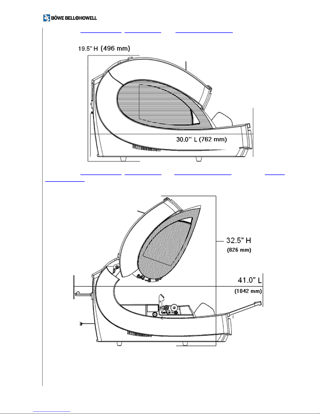
Side View-1 (Transport Cover, Back Imprinter, and Straight Pass-Through doors closed; Length
stipulated includes clearance for cables at the back of the scanner)
Side View-2 (Transport Cover
Table Extended; Length stipulated includes clearance for cables at the back of the scanner)
, Back Imprinter and Straight Pass-Through doors open; Feeder
Ngenuity Operator Manual
4 S008769 Rev A
Page 17
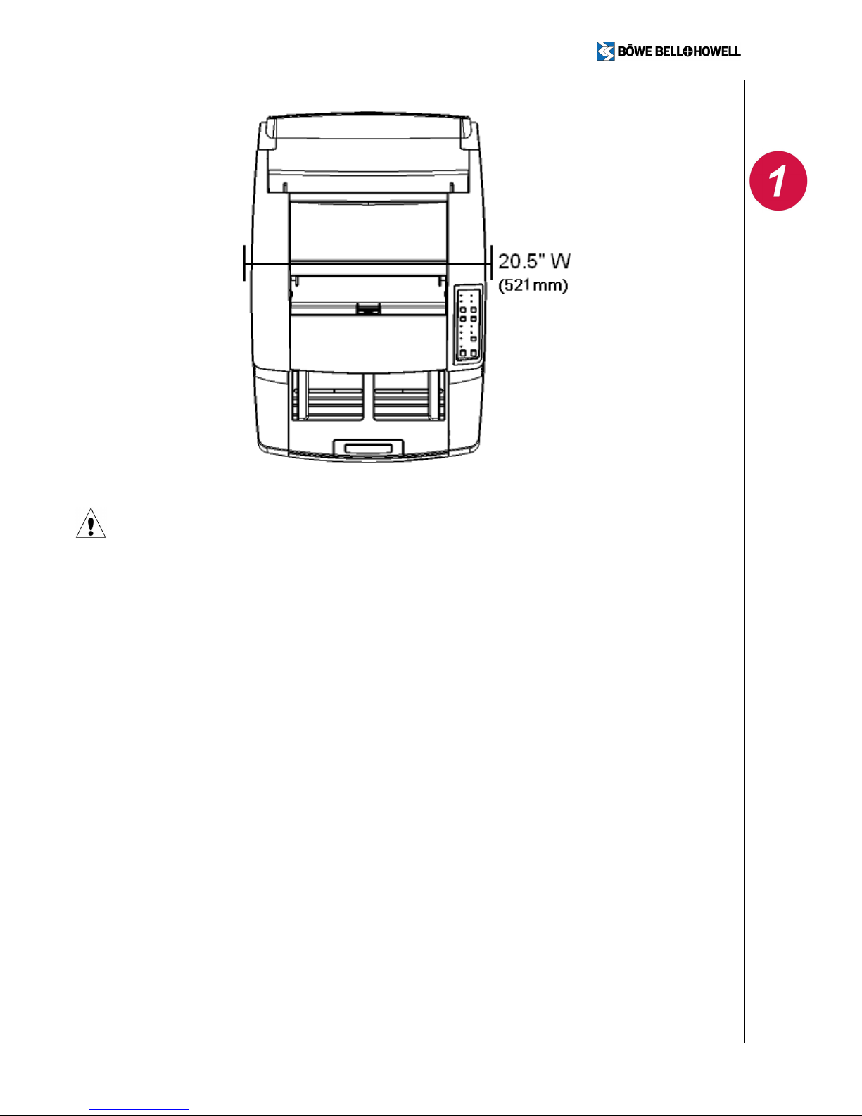
Top View
Getting Started
AUTION
C
Make sure to maintain an additional 4-5” (10-13 cm) of additional clearance at the front, back,
and both sides of the scanner for proper ventilation.
Place the scanner at the front edge of a sturdy, level surface. If the scanner’s straight passthrough feature is to be used, make sure to leave enough clearance at the back of the scanner
(see Side View-2 on page 4
).
1.4 External Component Identification
The external components that make up the scanner are identified in this section, along with a
detailed description of each.
S008769 Rev A 5
Page 18
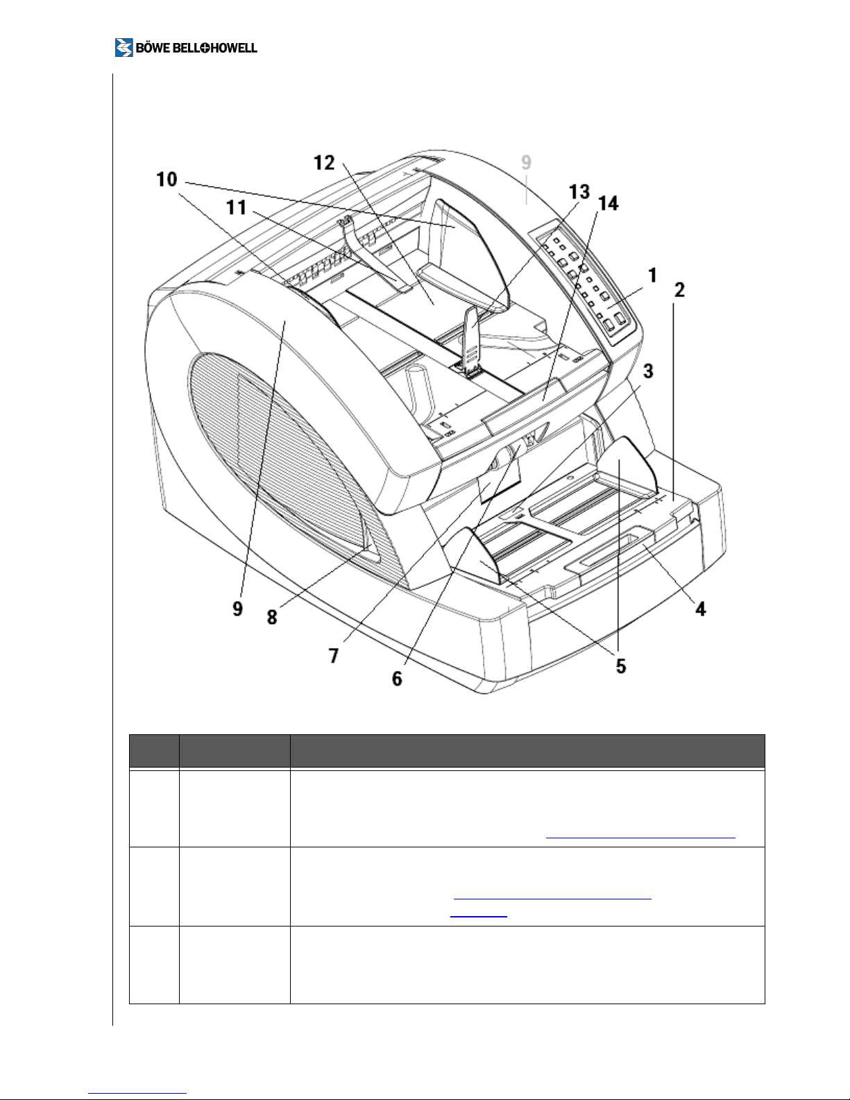
1.4.1 Scanner Front
Ref# Item Name Description
1 Control Panel The control panel allows the operator to manipulate certain scanner
2 Feeder Table The feeder table is where the document(s) to be scanned are placed by the
Ngenuity Operator Manual
3 Cork Pad The cork pad assists in preventing multifeeds by making it easier for the
6 S008769 Rev A
functions directly from the scanner itself. It is comprised of pushbutton
switches, LED indicators, pictogram legends, and text legends (for further
information about the control panel, see ”2.1
Operator. It can be raised and lowered by the Operator using the Down/
Set and Up buttons (see ”2.1.2
scanner’s control panel (#1 above
skimmer rollers to grab one document at a time from a batch to feed into
the scanner. It is a small, rectangular piece of cork that sits in a ‘well’ on
top of the feeder table.
Feeder Table” on page 23) located on the
).
Control Panel” on page 17).
Page 19

Ref# Item Name Description
4 Extender,
Feeder Table
5 Document
Feed Guides
(Left & Right)
6 Skimmer
Module
7 Separator
Roller Door
The extender for the feeder table acts as a support mechanism for longer
documents that extend out and beyond its standard length. The extra
support allows for better feeding of document(s) into the scanner’s
transport. The extender can be pulled out to add an approximate 7.0” (18
cm) of length to the feeder table.
The document feed guides and are used to guide document(s) into the
scanner’s transport with little or no skew. They can be width adjusted
independently of one another, which allows the Operator to left, right, or
center align documents for feeding into the scanner’s transport.
The skimmer (assembly) contains two rollers that assist in grabbing and
feeding documents from the feeder table into the scanner’s transport. The
skimmer assembly can be placed in an up position (manual feeding - see
2.1.1.5 Feed Modes, ‘
(automatic document feeding - see 2.1.1.5 Feed Modes, ‘
page 21). The skimmer rollers can get dirty and wear over time. They
require periodic cleaning and eventual replacement to maintain optimal
performance (refer to the section ‘
for more information).
Behind the separator roller door is the separator roller. The separator roller
assists in separating documents as they feed into the scanner’s transport
so as to avoid the occurrence of multifeeds. The separator roller can get
dirty and wear over time. It requires periodic cleaning and eventual
replacement to maintain optimal performance (refer to the section
‘
Maintenance” on page 57 in this manual for more information).
Manual Mode” on page 21) or a down position
ADF Mode” on
Maintenance” on page 57 in this manual
Getting Started
8 Transport
Cover Release
Levers
9 Transport
Cover
10 Document
Output Guides
(Left & Right)
11 Exit Deflector Hinged deflector that assists in the placement of documents in the Exit
There are two transport cover release levers, one located on the left side of
the scanner and one on the right. The Operator is required to pull one or
both lever mechanisms towards them while standing in the front of the
scanner to release and open the scanner’s transport cover for opening in
an upward position.
The transport cover is a hinged cover that can be opened to access the
scanner’s transport. It opens in an upward position and will stay open in a
full up position with the support of two gas springs that are located inside
the scanner - one on either side (see Side View-2 on page 4
image of the transport cover in a full up position).
The document output guides are used to guide the scanned document(s)
out of the transport into a neat stack on the exit tray
adjusted independently of one another, which allows the Operator to left,
right, or center align documents exiting the scanner’s transport, depending
on how the documents are fed into the scanner (see #5 above
Tray
a
. They can be width
to view an
)
S008769 Rev A 7
Page 20
Ref# Item Name Description
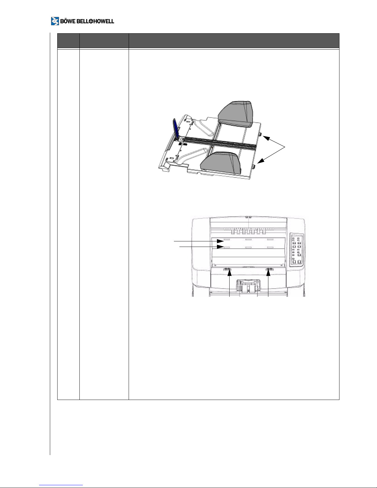
12 Exit Tray The exit tray is what the scanner ejects the document(s) into after they
b
have passed through the transport
the back of the tray that hinge into slots found in the scanner transport
cover, directly below where documents exit. There are two different levels
of slots that assist in positioning the exit tray if needed, depending on the
types of documents being scanned.
Top/Front View of Scanner - Exit Tray Removed
. It is held in place by tabs located on
Back of Exit Tray
Tabs
(slide into
slots)
Slots-
Top Row
Bottom Row
Stops for bracing
kickstand wire
The exit tray can be positioned in one of three ways:
Flat - Exit tray rests on top of the scanner in a flat, horizontal position, with
the tabs on the back of the tray hinged into the bottom-most row of slots in
the scanner.
Tilted Forward - Tabs at the back of the exit tray are installed in the uppermost slots (found directly below where documents exit the scanner). This
causes the exit tray to tilt in a downward position towards the front of the
scanner. This position is conducive to forward movement which can assist
long documents exiting the scanner.
Ngenuity Operator Manual
8 S008769 Rev A
Page 21
Ref# Item Name Description
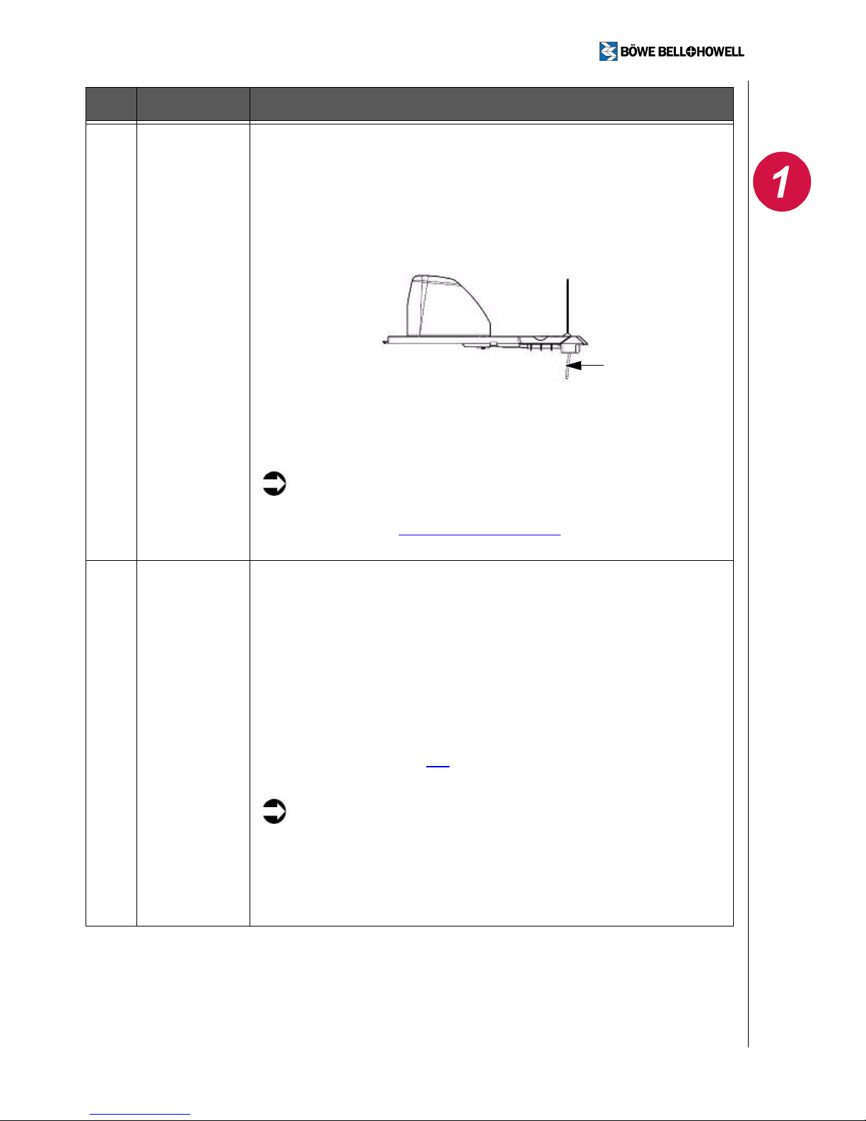
Tilted Backward - Tabs at the back of the tray are installed in the bottom-
most row of slots, and the hinged kickstand wire located on the bottom of
the exit tray is folded down and out. The kickstand wire is braced or
positioned against the stops found on the scanner’s upper center cover
(stops are located directly beneath the exit tray - see image above) so that
documents exiting the scanner are positioned to the back of the exit tray.
This is useful when scanning small documents such as checks.
Exit Table
(view from left side)
Located beneath the exit tray is a door that allows access to the front page
imprinter (if one is installed).
NOTE
Imprinters are a user-installable option available for purchase
from BBH. See ”4.1
imprinters.
Imprinter” on page 53 for more information on
Getting Started
Kickstand Wire
(folded out)
13 Guide,
Document
Stop
The document stop guide is adjustable for length and is used to stop
forward motion of the document(s) leaving the scanner’s transport. It
assists the document output guides in positioning the document(s) into a
neat stack. Pull the document stop guide out (towards the front of the
scanner) to lengthen the distance of forward motion documents travel
exiting the scanner or push the document stop guide in (towards the back
of the scanner) to shorten the distance of forward motion documents travel
when exiting the scanner.
The exit tray’s document stop guide should be placed in a down position
and not used when scanning extra long documents that require the use of
the exit tray extender (see #14
in this table).
NOTE
Positioning the document stop guide too close to the back of
the exit tray (towards the back of the scanner) can cause
documents to jam as they exit the scanner if the distance they
are allowed to travel is shorter then the length of the actual
documents themselves
c
.
S008769 Rev A 9
Page 22
Ref# Item Name Description
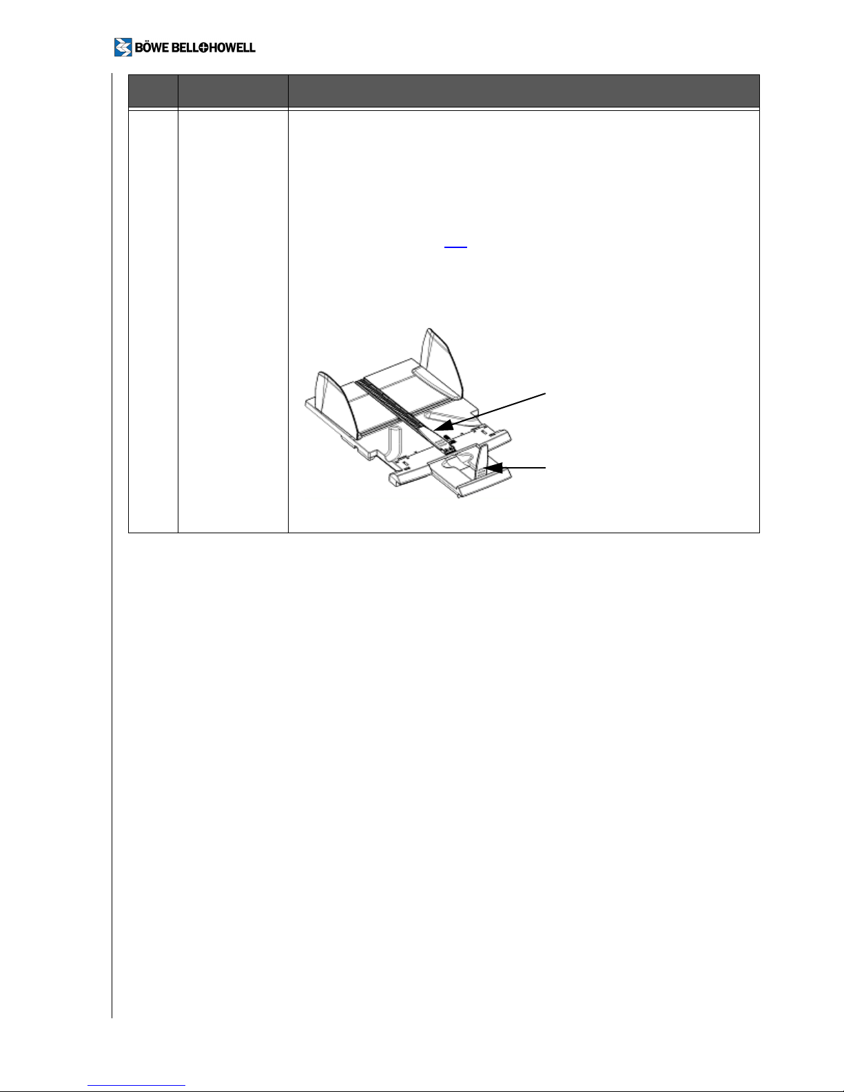
14 Extender, Exit
Tray
The exit tray extender is adjustable for length and acts as support for
document(s) exiting the scanner’s transport that exceed the standard exit
d
tray length
longer documents.
A second document stop guide is located on the end of the exit tray
extender. It performs the same function as the exit tray’s document stop
guide noted above (see #13
stop guide’s does not extend out along with the exit tray extender, the
second document stop guide is needed to stop the forward motion of extra
long documents leaving the scanner’s transport. It is to be placed in an ‘up’
position for use and folded down when not.
. Pull the extender out towards the front of the scanner for
in this table). Since the exit tray’s document
Exit Tray - Extender Pulled Out
Exit tray’s document
stop guide (down position)
Exit tray extender’s
document stop guide
(up position)
a. Does not apply if the scanner’s Straight Pass-Through feature is being used.
b. See footnote ‘a’ above
c. See footnote ‘a’ above
d. See footnote ‘a’ above
Ngenuity Operator Manual
10 S008769 Rev A
Page 23
1.4.2 Scanner Back
Getting Started
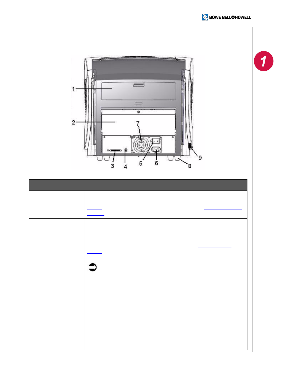
Ref# Item Name Description
1Back Imprinter
Door
2 Straight Pass-
Through Door
The back imprinter is installed and accessed through this door. It requires
an additional 3.5” (9 cm) of clearance to open fully (see Side View-2 on
page 4). For more information about the imprinter, see ”4.1 Imprinter” on
page 53.
Enables the use of the Straight Pass-Through scanning feature. When the
straight pass-through door is open, documents are fed straight through the
scanner and exit out the back of the scanner. This is useful for scanning
thick or stiff documents. The straight pass-through door requires an
additional 3.5” (9 cm) of clearance to open fully (see Side View-2 on
page 4).
NOTE
While scanning documents in rotary mode (straight passthrough feature NOT being used), do NOT open the straight
pass-through door. Doing so can cause a physical paper jam or
cause the scanner’s firmware to issue a paper jam error.
3SCSI
Connector
Connector for attaching optional SCSI cable (cable and SCSI card not
provided). For more information about the optional SCSI connection, see
”4.2
SCSI Connection” on page 53.
4 USB
Connector
5 Power Switch Toggle switch used to apply or remove power to the scanner. ‘I’ = ON; and
S008769 Rev A 11
Connector for attaching supplied USB cable which also attaches to the
host PC and is used to establish communication between the two.
‘O’ = OFF.
Page 24

Ref# Item Name Description
6 Power
Connector
7 Fan Fan for cooling the scanner. The fan is part of the scanner’s power supply.
8 Foot Rubber appendage that the scanner sits on and allows for clearance below
9 Intake Vent The vent that the power supply’s fan uses to draw air in for cooling. It is
Connector for supplied power cable.
Make sure to properly vent the scanner for optimal performance (see
”1.3
Operating Environment” on page 3 for more details).
the scanner. There are four total; 2 on either side.
important that the scanner not be positioned in such a way that the intake
vent is blocked in any way.
CAUTION
Make sure to maintain an additional 4-5” (10-13 cm) of additional
clearance at the front, back, and both sides of the scanner for
proper ventilation.
1.5 Unpacking/Repacking
Before completely unpacking your scanner, inspect the shipping cartons and their contents for
any signs of damage. If there is damage, notify the freight carrier immediately to file a damage
claim.
Save all of the shipping cartons and packaging materials that come with your Ngenuity scanner.
If it is ever necessary to move or ship the unit or any of its accessories, pack them in their original
cartons.
Scanners and/or accessories must be returned in the original packing carton and inserts.
BÖWE BELL + HOWELL and the carrier will not accept responsibility for damages incurred
during shipping if the scanner is returned in anything but the original carton and
packaging material.
If you need to return the scanner and do not have the original packaging material, a packaging kit
can be provided to you. Contact the BBH Sales at 1-800-SCAN-494 for more details (charges
may apply).
W
ARNING
The scanner weighs approximately 112 pounds (51 kg). Be sure to incorporate the appropriate
Ngenuity Operator Manual
manpower (taking into consideration your lifting capabilities) before moving or lifting the
scanner.
12 S008769 Rev A
Page 25

1.5.1 What You Should Have Received
The following items are included with each scanner shipment. Confirm the receipt of each. If you
did not receive one of the items listed, please contact our Scanner Help Desk at 1-800-SCAN-
495.
• Ngenuity scanner
• 10’ Power cord and USB cable
• Ngenuity Installation CD, which includes:
- Ngenuity Operator manual
- Ngenuity Quick Install Guide
- Windows
-VRS Software
- VRS User Manual and Release Notes
- USB Drivers
- Cleaning and Consumable Price Sheets
- Adobe Reader
- Warranty Card
®
-based Ngenuity Operator Utility (NOU)
Getting Started
- Quick Reference Maintenance Guide
- Ngenuity Roller and Cleaning Kit inventory lists and order forms
- HiZoom Color Utility
• Warranty card
• Camera calibration kit
• Quick Reference Maintenance Guide
• Starter Cleaning Kit
• BBH Scanners Brochure
1.6 Specifications
This section details the scanner’s system specifications, as well as the specifications (minimum
and recommended) for the host PC connected to the scanner.
S008769 Rev A 13
Page 26

Model 9150 9125 9090
Scanning
Speed, Letter
Size, Bitonal,
Color,
Grayscale,
Simplex/Duplex
Daily Duty Cycle Unlimited
Roller Life (bond) 600,000 scans
Resolution Output: 600 dpi; Optical: 600 dpi
Camera Technology
Lighting Technology White LEDs - instant warm-up designed to last the life of the scanner
Image Enhancement Onboard Ngenuity VRS 4.2 (or greater) Professional
Interface USB™ 2.0 (cable included); SCSI III
Support Drivers (included) ImageControls, ISIS, TWAIN (through VRS)
Multifeed Detection Ultrasonic Multifeed featuring: Three sensors, Preemptive Ignore,
Imprinting Optional user-installable pre and/or post scan imprinter, time and
Document Size (W, L) 1.7 x 2.5 in. (43 x 64 mm) to 12.5 x 40 in. (318 x 1016 mm)
Doc Size (Very Long Document
Mode) Up to 219 yards (200 m)
Maximum Image Width 12.25 in. (311 mm)
Paper Thickness Rotary: .0015 - .035 in. (.038 mm - 0.89 mm)
Paper Weight 7 to 320 lb. bond (30 - 1,200 gsm)
Feeder Capacity
(20 lb. bond / 75 gsm paper) 700 documents - Variable Feeder Tray Capacity Control
Scanner Size (HxWxD)
Scanner Weight 112 lbs. (51 kg)
Power Requirement AC 100-120V / 220-240V; 1.9/.9A; 60/50Hz
Power Consumption 175W (maximum); 6.7W (Sleep Mode)
Environment Temp: 50°F to 100°F (10°C to 37.8°C);
Additional Features Straight Pass-Through Paper Path, Special Documents Mode,
Additional Contents USB™ cable, Installation Resource CD with Ngenuity™ Operator
Landscape
at 200 dpi
Portrait at
200 dpi
a
Ngenuity Operator Manual
Additional Options User-installable pre and/or post scan imprinter with time and date
a. Straight pass-through door closed
150 PPM / 300 IPM 125 PPM / 250 IPM 90 PPM / 180 IPM
120 PPM / 240 IPM 100 PPM / 200 IPM 70 PPM / 140 IPM
VRS Ignore, Ignore by Size
date stamping, 72 characters
Straight Pass-Through: .0015 - .070 in. (.038 mm - 1.78 mm)
19.5 x 20.5 x 30 in. (49.5 x 52.1 x 76.2 cm)
Humidity (non-condensing): 10% to 80%
Advanced Color Functionality
Utility and Ngenuity™ VRS Professional, Power Cord, Starter
Cleaning Kit, Camera Calibration Kit
stamping, Roller Kit, Cleaning Kit, Power Conditioner
1.6.1 Scanner
Trilinear 7.6K CCD
with normal use
14 S008769 Rev A
Page 27

1.6.2 Software
The following are BBH’s recommended system requirements for the host PC as they pertain to a
color scanner. These specifications pertain to the Ngenuity Operator Utility (NOU) and Ngenuity
compatible VRS Professional only:
Host PC Operating System
Microsoft® Windows® Vista Businessa, Windows® XP Professional with SP2, Windows® 2000
Professional with SP4
Host PC Minimum Specifications Host PC Recommended Specifications
®
Core™2 Duo / AMD Athlon™ 64 x 2
Intel
Intel® Pentium® D / AMD Athlon™ 2 GHz
HDD: 250 GB HDD: 500 GB
DIMM DDR 2700: 1 GB DIMM DDR 3200: 2 GB
PCI Bus 32-Bit
USB 2.0
Dual Core, 2.4 GHz or better
Getting Started
Video AGP or PCIe: 128 MB
SCSI Card - Adaptec 29160 Regular and Low Profile
a. Microsoft® Windows® Vista Business 32-bit or 64-bit compatible with USB connection;
Microsoft
b. SCSI is an optional connectivity type for Ngenuity scanners. If using USB to connect your
scanner to the host PC, a SCSI card is not required. For more information on SCSI connectivity,
see ”4.2
®
Windows® Vista Business 32-bit only compatible with SCSI connection.
SCSI Connection” on page 53 in this manual.
b
1.7 Installation
WARNING
The scanner weighs approximately 112 pounds (51 kg). Be sure to incorporate the appropriate
manpower (taking into consideration your lifting capabilities) before moving or lifting the
scanner.
For instructions on installing the scanner, refer to the Ngenuity Quick Install Guide (S008842). A
hard copy of the Quick Install Guide is included with the scanner, and an electronic copy exists on
the scanner’s installation resource CD-ROM. If you are unable to retrieve an Ngenuity Quick
Install Guide from these sources, one can be downloaded from www.bbhscanners.com
.
S008769 Rev A 15
Page 28

Ngenuity Operator Manual
16 S008769 Rev A
Page 29
Operating Your Scanner
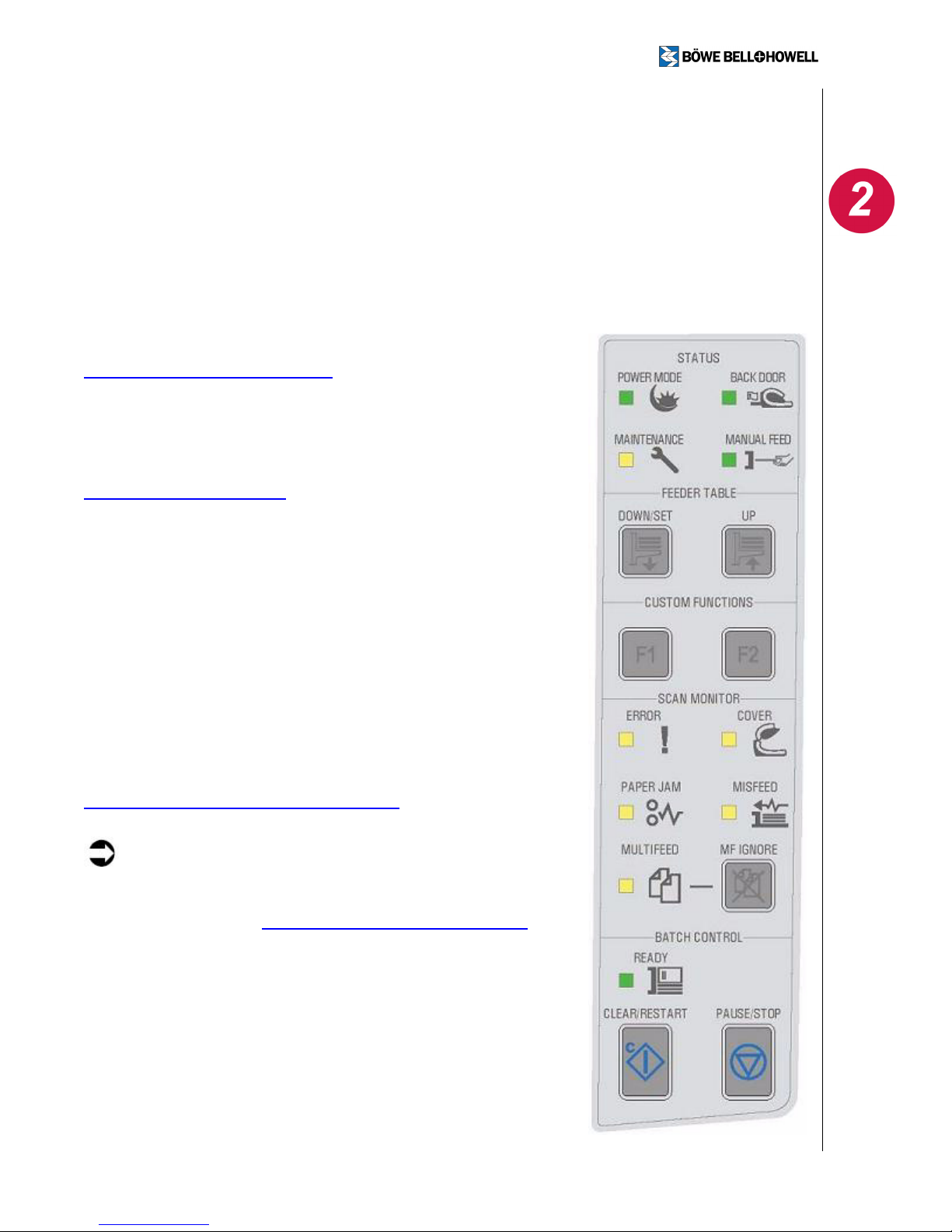
The scanner’s control panel and the Ngenuity Operator Utility are detailed in this section.
2.1 Control Panel
The control panel is located on the front of the scanner (see
”1.4.1
switches, LED indicators, universal graphics (pictogram legends),
and text legends that allow the Operator to manipulate basic
scanner controls.
Through the use of the LED indicators and audible tones (see
”2.2.3.4
notification device for the Operator as to the current state of the
scanner (e.g. power state, maintenance needed, active features,
errors, etc.). It is divided into five sections:
Scanner Front” on page 6). It is comprised of pushbutton
Audio” on page 38), the control panel also acts as a
Operating Your Scanner
•Status
• Feeder Table
• Custom Functions
• Scan Monitor
• Batch Control
Some of the functionality contained within these sections
correlates with the settings and information found in the Ngenuity
Operator Utility, which is discussed in greater detail in
”2.2
Ngenuity Operator Utility” on page 29.
OTE
N
The control panel remains powered during SLEEP mode;
however, it will be un-powered during the OFF mode, i.e.,
powered OFF (see ”2.1.1.1
more information).
Power Mode LED” on page 18 for
S008769 Rev A 17
Page 30
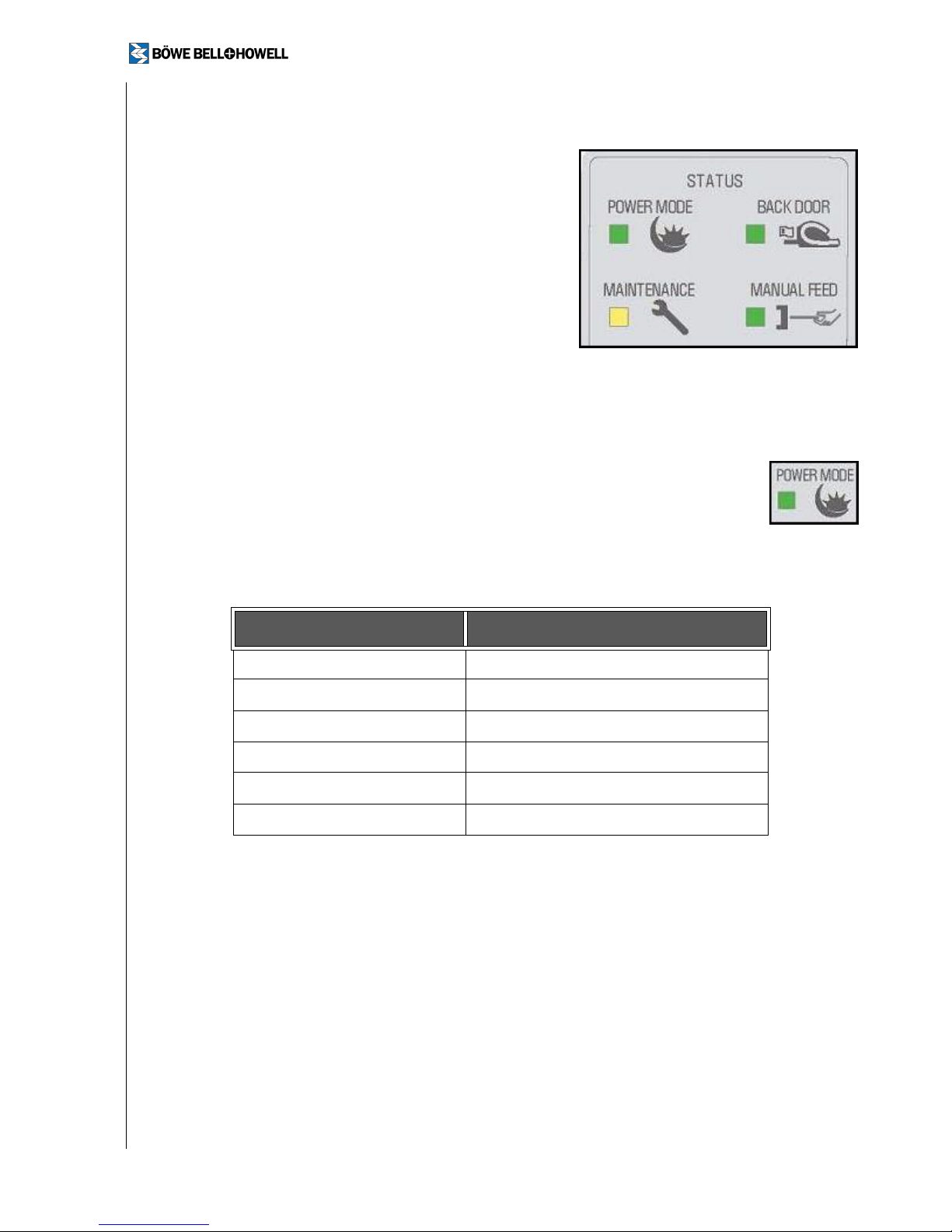
The Status area of the control panel consists of the
following LED indicators: POWER MODE; BACK DOOR;
MAINTENANCE; and MANUAL FEED.
2.1.1.1 Power Mode LED
The POWER MODE indicator uses an LED to indicate the various power states
(modes) or the transition between power modes. When lit, the POWER MODE
LED indicator is green in color.
2.1.1 Status
The table below identifies the various actions of the POWER MODE LED depending upon the
scanner’s power state:
Power State or Transition Power Mode LED
OFF Off
READY Blinking, fast rate
SLEEP > READY Blinking, fast rate
READY/ACTIVE Steady
READY > SLEEP Blinking, fast rate
SLEEP Blinking, slow rate @ 10% duty cycle
Once in SLEEP mode, the POWER MODE LED is the only indicator that will be lit; all others are
off (not lit) in order to reduce power consumption.
Depending on the current power mode, the control panel’s pushbuttons perform different actions.
The table below identifies the functionality of the control panel’s pushbuttons during the various
power modes and transitions:
Ngenuity Operator Manual
18 S008769 Rev A
Page 31

Power State or Transition Pushbutton Function
OFF N/A - control panel and scanner electronics not powered
READY Pushbuttons are ignored during this initialization transition
SLEEP > READY Pushbuttons are ignored during this initialization transition
READY/ACTIVE All pushbuttons perform their normal operational functions. Press
and hold the STOP pushbutton for 5 seconds to put the scanner
immediately to sleep
READY > SLEEP Momentary press of any pushbutton re-triggers the sleep timer and
prevents transition to SLEEP mode; scanner resumes a READY
mode
SLEEP Momentary press of any pushbutton wakes up the scanner (starts
the SLEEP > READY transition)
2.1.1.2 Back Door LED
The BACK DOOR LED indicator displays the status of the scanner’s straight passthrough door located in the back of the scanner (see ”1.4.2
page 11). When lit, the BACK DOOR LED indicator is green in color.
The table below identifies the various actions of the BACK DOOR LED depending upon the state
of the scanner’s straight pass-through door:
Scanner Back” on
Operating Your Scanner
Back Door State Back Door LED
Straight pass-through door is closed; normal
full transport path to exit tray is in use
Straight pass-through door is open; documents being scanned will be transported to
rear exit rather than normal exit tray
OFF (not lit)
STEADY ON
2.1.1.3 Maintenance LED
When lit, the MAINTENANCE LED indicates that maintenance or service
conditions exist in the scanner (see ”2.2.2.3
more information). When lit, the MAINTENANCE LED is yellow in color.
Maintenance Monitor” on page 35 for
S008769 Rev A 19
Page 32

The table below identifies the various actions of the MAINTENANCE LED depending upon the
state of the scanner:
Scanner State Maintenance LED
System OK; no maintenance currently
required
Maintenance needed (see ”2.2
Operator Utility” on page 29 for more
information)
Scanner Busy/Offline; occurs when scanner is
in off-line mode and not capable of scanning
(occurs when scanner is in a special mode
such as ADF Test, during camera calibration,
while downloading firmware, performing an
imprinter cleaning)
Self-test failure; needs service (coincides with
the reminders displayed in the Maintenance
Monitor of the Ngenuity Operator Utility (NOU)
- see ”2.2.2.3
page 35)
N
OTE
In the event a self-test failure occurs, contact your local BBH Authorized Service Provider
(ASP). A list of BBH ASPs can be found on our web site at www.bbhscanners.com
Maintenance Monitor” on
Ngenuity
OFF (not lit)
SLOW BLINKING
FAST BLINKING
STEADY ON
.
2.1.1.4 Manual Feed LED
The MANUAL FEED LED indicates whether or not the feed mode has been
changed from the normal/default ADF (Automatic Document Feed) mode to the
Manual mode. When lit, the MANUAL FEED LED is green in color.
The table below identifies the various actions of the MANUAL FEED LED depending upon the
feed mode setting on the scanner (see ”2.1.1.5
Feed Modes” on page 21 for more information):
Feed Mode Setting Manual Feed LED
ADF feed mode OFF (not lit)
Manual feed mode STEADY ON
Ngenuity Operator Manual
20 S008769 Rev A
Page 33

2.1.1.5 Feed Modes
The Ngenuity scanner has four available feed modes for feeding documents into the scanner’s
transport: ADF mode; Manual mode; Assisted Manual mode (type of Manual mode); and Test
Feed mode.
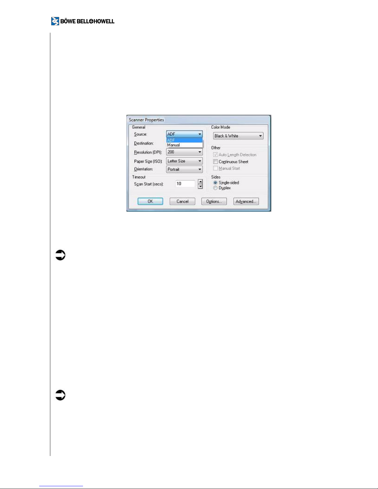
With the exception of the Test Feed mode, the type of feed mode the scanner uses is set by the
Operator through the scanner properties window that resides within the software application being
used for scanning.
ADF MODE
ADF mode is the default feed mode for the scanner. It is used for feeding batches of documents
that are similar in size and weight. After being placed on the feeder table, a batch of documents is
fed automatically into the scanner’s transport one at a time.
MANUAL MODE
Manual mode is used to feed documents that can’t tolerate the separation operation of ADF Mode
(e.g. multiple forms). In Manual mode the Operator is required to manually feed documents into
the scanner’s transport one at a time. When scanning in Manual mode, the MANUAL FEED LED
on the scanner’s control panel will be lit (see ”2.1.1.4
To scan documents using Manual mode, perform the following:
N
OTE
For demonstration purposes, VCDemo (scanning application that automatically loads with the
Ngenuity VRS Professional software) is used in the following procedure.
Manual Feed LED” on page 20).
Operating Your Scanner
1. Power ON the scanner (see 1.4.2 Scanner Back, “Power Switch” on page 11) and wait to the
scanner’s initialization sequence to complete
2. Place the skimmer in the up position (for skimmer identification, go to ”1.4.1
on page 6)
3. Boot up the host PC
4. Launch the scanning application (in this example, VCDemo)
5. Select the scanner
VRS ImageControls®-based Applications
- Bowe Bell+Howell 9000 with VRS
- Bowe Bell+Howell 9000 with VRS with AIPE
S008769 Rev A 21
Scanner Front”
Page 34
VRS ISIS-based Applications
- Kofax VRS Scanner
VRS TWAIN-based Applications
- Kofax Software VRS - TWAIN
6. Open the scanning application’s Scanner Properties window
7. Using the drop down arrow for the Source control, select Manual
8. Save the change (in the image above - VCDemo Scanner Properties window - clicking the OK
button saves the changes)
N
OTE
The MANUAL FEED LED on the scanner’s control panel does not automatically light. It will
light to signal that the scanner is in Manual mode once a scan command (single or batch) is
issued from the scanning software.
If the Operator changes the feed mode from Manual to ADF, the MANUAL FEED LED won’t turn
off until a scan command (single or batch) using ADF mode is issued from the scanning
application.
9. The feeder table will not rise to the manual feed position until a scan command is issued.
Issue a single scan command or a batch scan command, and when the feeder table is in the
full up position, begin feeding documents, one at a time, into the scanner’s transport.
Take care to feed each document far enough into the scanner so that the scanner is able to
grasp the document and feed it into and through the transport
N
OTE
Ngenuity Operator Manual
To lower the feeder table for ADF mode scanning, the Operator must lift the skimmer module
to the full up position, make sure the paper tray is empty, and change the feeding mode from
Manual to ADF in the scanning application and issue a scan command (single or batch).
When a single scan command is issued, the scanner’s transport begins to run. The Operator
is able to feed documents through the scanner (one at a time); however, because a single scan
22 S008769 Rev A
Page 35

command was issued, only the first document’s image is kept. To scan and save multiple
images, issue a batch scan command.
The scanner will stay in Manual mode until the Operator sets it back to ADF mode, or
reestablishes contact between the scanning application and the scanner.
ASSISTED MANUAL MODE
The Assisted Manual mode operates the same way as the Manual mode, with the exception of
the skimmer being in the down position (see step #2
assists the Operator in feeding the documents into the scanner so that the Operator does not
have to push or feed the documents as far into the scanner’s transport as they would in regular
Manual mode.
above). The skimmer in a down position
TEST FEED MODE
The Test Feed mode is used to test and verify the scanner’s feeding capabilities, as well as to
feed the transport cleaning sheets (see ”5.3.5
Operator or service technician to feed documents without having to generate a scan command
from the host PC.
Unlike ADF mode and Manual (Assisted) mode, the Test Feed mode is set or activated from
within the Custom Functions section of the Ngenuity Operator Utility or NOU (see ”2.2.3.3
Functions” on page 38 for more information) and is only functional when the scanner is set to ADF
mode in the scanning application.
Cleaning the Transport” on page 82). It allows the
Custom
2.1.2 Feeder Table
Operating Your Scanner
The next area of the control panel is the Feeder Table. The
Feeder Table section contains two pushbutton switches: DOWN/
SET; and UP. These two pushbutton switches control the feeder
table bottom position for ADF mode, allowing for “continuous”
batch size selection.
How it works...
• With the feeder empty, press and hold the DOWN/SET pushbutton to drive the feeder downward. Release the pushbutton and the table movement stops. This current position becomes
the new bottom table stop. If the DOWN/SET pushbutton is held indefinitely, table movement
stops at the bottom physical limit.
• With the feeder empty, press and hold the UP pushbutton to drive the feeder up. Release the
pushbutton and the feeder movement stops. This position becomes the new bottom table
position.
S008769 Rev A 23
Page 36

• With the feeder full (i.e. paper sensor covered), the UP pushbuttom performs no function. A
DOWN pushbutton press will set the current stack size and reset the feeder bottom position
accordingly.
2.1.3 Custom Functions
The next area of the control panel is labeled Custom Functions.
The Custom Functions section contains two pushbutton
switches, F1 and F2, that perform special Operator-selectable
functions.
The functions that the F1 and F2 pushbuttons perform are
assigned through the Ngenuity Operator Utility (NOU) where
there is a pre-defined list of functions that the Operator can choose from (see 2.2.3.3 Custom
Functions for more information).
2.1.4 Scan Monitor
The third area of the control panel is the Scan Monitor section
which contains error indicators in the form of LEDs that notify
the Operator that an error has occurred while scanning. The
error indicators are: ERROR; COVER; PAPER JAM; MISFEED;
and MULTIFEED.
Within the Scan Monitor section is also a pushbutton labeled MF
IGNORE. This pushbutton allows the Operator to ignore a
single multifeed occurrence
Each error indicator LED and the MF IGNORE pushbutton are
described in more detail in the following sections.
2.1.4.1 Error LED
When lit, the ERROR LED indicator is yellow in color. It is lit when any scanner
error occurs that is not handled by one of the other dedicated indicators (i.e. Paper
Jam, Cover, Misfeed, etc.).
If the ERROR LED is lit, refer to the NOU and your scanning application for more
information.
Ngenuity Operator Manual
24 S008769 Rev A
Page 37

2.1.4.2 Cover LED
When lit, the COVER LED indicator is yellow in color. It is lit when the scanner’s
transport cover is open.
If this error occurs during scanning, pressing the CLEAR/RESTART pushbutton on
the control panel is required after the open cover is closed to restart the batch and turn the
COVER LED indicator off.
When not scanning, the COVER LED indicator identifies that the transport cover is open, but
pressing the CLEAR/RESTART pushbutton is not required to turn it off.
2.1.4.3 Paper Jam LED
When lit, the PAPER JAM LED indicator is yellow in color. It is lit when a paper jam
occurs. The PAPER JAM LED indicator will light if the CLEAR/RESTART
pushbutton is pressed after a paper jam occurs, but the paper jam condition still
exists (i.e. paper is still covering one or more page-detect sensors).
To re-set (turn-off) the PAPER JAME LED, open the scanner’s transport cover and remove all
paper debris from the transport. Close the transport cover and press the CLEAR/RESTART
pushbutton.
N
OTE
While scanning documents in rotary mode (straight pass-through feature NOT being used), do
NOT open the straight pass-through door. Doing so can cause a physical paper jam and a
paper jam error.
Operating Your Scanner
When lit, the MISFEED LED indicator is yellow in color. When one of the following
errors occur it will display a solid light:
• Skimmer Timeout: Skimmer is active, but the document to be scanned does
not move out of the feeder tray (commonly due to roller slippage)
• Feeder Jam: The document to be scanned is fed from the feeder tray, but does not reach the
scanner transport within the expected transit time
S008769 Rev A 25
2.1.4.4 Misfeed LED
Page 38

2.1.4.5 Multifeed LED & MF Ignore Pushbutton
When lit, the MULTIFEED LED indicator is yellow in color. It is lit
when the scanner indicates a multifeed error or warning. It will
either light steady (remain lit), momentarily, or blink depending on
the multifeed condition.
For example:
• If the multifeed mode is set to STOP (error), the MULTIFEED LED indicator remains lit
(steady) and the scanner stops
• If the multifeed mode is set to NOTIFY (warning), the MULTIFEED LED indicator will light
momentarily, along with an audible signal or prompt for each distinct multifeed that occurs
while the scanner is running
For more information on how to set the Multifeed mode condition, refer to ”3.2.1.1
Mode” on page 46 in this manual.
OTE
N
If the scanner’s audio feature has been set to Mute (see ”2.2.3.4 Audio” on page 38), the
multifeed alarm that occurs with the Notify and Stop options will not be audible to the
Operator.
Multifeed
VRS MULTIFEED IGNORE
When scanning using VRS, if a multifeed error has already occurred (MULTIFEED LED is lit and
the batch has stopped), pressing the MF IGNORE pushbutton instructs VRS to retain the image
and restart the batch. In this instance, there is no need to press the CLEAR/RESTART
pushbutton (for more information on the CLEAR/RESTART pushbutton, go to ”2.1.5.2
Restart Pushbutton” on page 28 in this manual).
How it works...
When a multifeed occurs and the multifeed mode condition is set to STOP, the Operator has two
choices:
Delete the Multifeed Image
1. Using the Custom Function pushbutton on the control panel that is set to “Page Eject”,
eject the multifeed document from the transport (refer to ”2.2.3.3
page 38 for more information on Custom Functions)
Custom Functions” on
Clear/
2. Correct whatever it was that caused the multifeed and place the multifeed document back
in the feeder on the top of the batch of documents to be scanned
Ngenuity Operator Manual
3. Press the CLEAR/RESTART pushbutton on the scanner’s control panel to automatically
restart scanning
26 S008769 Rev A
Page 39

Retain the Multifeed Image
- Press the MF IGNORE pushbutton on the scanner’s control panel. After a couple of seconds, the scanner will automatically eject the multifeed document and continue scanning
documents, retaining the multifeed image
PREEMPTIVE MULTIFEED IGNORE
The MF (MULTIFEED) IGNORE pushbutton toggles the multifeed ignore feature on/off. When
on, the scanner will ignore the multifeed sensor during the next page fed (one page only), and the
MULTIFEED LED will blink to indicate the activated ignore state.
It works in a preemptive manner in that during batch scanning, the Operator can avoid an
impending multifeed alarm without forcing a batch stop by pressing the MF IGNORE pushbutton
during a batch scan. Doing so turns off the MF alarm detection for a single page starting with the
next leading edge seen by the page entry sensor. To turn off MF detection for a series of
documents, press and hold the MF IGNORE pushbutton.
2.1.1 Batch Control
Operating Your Scanner
The final or bottom area of the control panel is labeled Batch
Control. The Batch Control section contains an LED indicator and
two pushbuttons that deal specifically with scanning start and
stop.
2.1.5.1 Ready LED
The READY LED indicator is green in color. It is lit when the Ngenuity scanner is
ready to scan (feeder ready, no unresolved errors, and the scanner is not otherwise
busy, i.e. internal operations due to activity of Ngenuity Operator Utility).
• ADF Feed Mode - the READY LED is lit steady when the documents to be scanned are in
position and ready to feed (assuming no error conditions are active)
• Manual Feed Mode - the READY LED is lit steady when scanning can begin and during
scanning
S008769 Rev A 27
Page 40

2.1.5.2 Clear/Restart Pushbutton
The CLEAR/RESTART pushbutton is used for the following:
• To clear an error (one of the error indicators on the control panel is lit) and
resume scanning. This is only successful if whatever caused the error to
occur in the first place is resolved (i.e. paper removed from the transport which
caused a paper jam error and the PAPER JAM LED to light).
• To clear a multifeed error (when using VRS), which tells VRS to discard the multifeed image
and rescan the document
• To resume scanning after a batch pause
2.1.5.3 Pause/Stop Pushbutton
The PAUSE/STOP pushbutton is primarily used to stop the scanner’s transport.
• If there is no scan command queued, no documents in the transport, and no feeding in progress, pressing this pushbutton simply stops the transport prior to the
automatic transport timeout. This does not cause any errors
OTE
N
The automatic transport timeout is 20 seconds. The 20 seconds is not Operator adjustable.
• If the scanner is feeding documents, pressing this pushbutton once will initiate a controlled
transport motor stop (i.e. stop feeder and continue processing documents until the transport is
empty), and a host “scanner paused” error will occur
• If the PAUSE/STOP pushbutton is pressed twice or pushed and held for more than one second, a hard stop will occur (scanning stops with documents remaining in the transport) along
with a host “scanner stopped” error (this host error will not happen if the scanner is running in
Test mode). Press the Clear/Restart pushbutton to resume scanning (there is a slight delay
before scanning resumes).
N
OTE
If the Clear/Restart pushbutton is pressed before all documents are cleared from the transport
and one of those documents is covering the exit sensor (refer to images found in “
Transport Sensors” on page 76 for exit sensor location), an audible alarm on the scanner will
sound and the PAPER JAM LED will light. Clear the transport of all documents by pressing
and holding the Custom Function pushbutton that is programmed to ‘Page Eject’ (see
”2.2.3.3
scanning (there is a slight delay before scanning resumes).
Custom Functions” on page 38) and then press the Clear/Restart pushbutton to resume
Ngenuity Operator Manual
The PAUSE/STOP pushbutton is also used to immediately put the scanner in SLEEP mode by
pressing and holding the pushbutton for 5 seconds or longer. This can only be accomplished
when the scanner is fully idle (no scan commands queued) and the transport is not running).
Cleaning
28 S008769 Rev A
Page 41

2.2 Ngenuity Operator Utility
The Ngenuity Operator Utility (NOU) is a Windowsbased application that communicates with the
scanner to provide and monitor scanner connectivity,
statuses and alerts, and allows Operators to set some
of the scanner’s configuration parameters.
An Ngenuity scanner must be properly connected to
the host PC the NOU resides on and powered ON for
the NOU’s controls to be accessible and functioning.
To establish communication between the scanner and the NOU, perform the following:
Operating Your Scanner
1. Properly connect the USB cable to the back of the scanner (see 1.4.2. Scanner Back, “
Connector” on page 11) and to the host PC
OTE
N
If using the optional SCSI connection, go to ”4.2 SCSI Connection” on page 53 in this manual for
more information.
2. Power ON the scanner (see 1.4.2 Scanner Back, “Power Switch” on page 11) and wait to the
scanner’s initialization sequence to complete
3. Boot up the host PC
4. Launch the NOU by double clicking the icon located on the host PC’s Desktop (for
instructions on installing the scanner - including the NOU - refer to the Ngenuity Quick Install
Guide (S008842). A hard copy of the Ngenuity Quick Install Guide is included with the scanner, and an electronic copy exists on the scanner’s installation CD. If you are unable to
retrieve an Ngenuity Quick Install Guide from these sources, one can be downloaded from
www.bbhscanners.com
The NOU will run through an initialization sequence that includes a number of self tests.
When communication with the scanner is established, the scanner and connection type will be
displayed on the Home screen of the NOU (see ”2.2.2.1
)
Scanner Model” on page 34)
USB
S008769 Rev A 29
Page 42

If the NOU does not display that communication has been established, check
to make sure the USB cable is properly connected to both the scanner and
host PC. Power OFF the scanner and host PC, and run through the
connection procedure again. If it fails a second time, contact the BBH Help
Desk at 1-800-SCAN-495
N
OTE
Be aware that the NOU’s controls remain accessible, but are not functional after connectivity
with the scanner has been established and then the scanner is powered OFF or the USB cable
is disconnected. Any changes made to existing settings with the scanner powered OFF will
not be present at next power ON.
If the scanner is powered OFF and the NOU application closed, the scanner must be powered
ON in order to reestablish connectivity to the NOU.
If the scanner does not pass one or more of its self tests, the NOU will display an error message.
For a list of possible error messages and their resolutions, go to “
Error Messages” on page 85. If the problem persists, contact the BBH Help Desk at 1-800-
SCAN-495.
The NOU contains a menu bar across the top of the main Utility window that consists of these
menu items: Scanner; Language; and Help. Within the main Utility window are housed three
screens used to monitor and configure basic scanner parameters and tasks. They are: Home;
Settings; and Maintenance. The default screen is the Home screen which is visible when the
NOU is initially launched.
Each of the three screens use various icons and text messages to alert the Operator to the status
of the different scanner functions, as well as set parameters. The Home screen also incorporates
hyperlinks that will navigate the Operator to specific areas in the other two screens within the
NOU that require attention.
A description for all of the items mentioned above is given in more detail below.
Self Test
2.2.1 Menu Bar
The NOU contains a menu bar across the top of the main Utility window that consists of these
menu items: Scanner; Language; and Help.
Ngenuity Operator Manual
30 S008769 Rev A
Page 43

Clicking on the Scanner menu displays the following three
selections: “Details”; “Update Firmware”; and “Exit”. The
“Details” and “Update Firmware” selections are only
accessible (not grayed out) if the Ngenuity scanner is
connected to the host PC that the NOU is installed on.
Clicking “Details” from the Scanner menu will
display a dialog window containing version
information for all scanner firmware components,
along with camera information. In addition, the
scanner model identification is displayed in the
dialog window.
2.2.1.1 Menu - Scanner
Operating Your Scanner
DETAILS
N
OTE
The version information contained in the
screen shot (right) is for demonstration
purposes only and should not be used as a
reference for scanners in the field.
The “Details” dialog window also contains 3
buttons, which are: Save As...; Copy to
Clipboard; and Close.
Clicking the Save As... button opens a second dialog window from which the Operator or service
technician can save the details anywhere on the host PC or a network (if connected) as a text file
(.txt).
This function uses the default file path as that of the NOU itself, with a preselected file name of
“BBHScannerModel” (e.g. BBH9125DC). Both of these items (file path and name), can be
changed by the user; however, they both will revert back to their defaults whenever the NOU is
closed and re-started.
N
OTE
In future releases (updates) of the NOU, when launching the utility, instead of reverting to it’s
default, the file path will remember and display the last used (saved to) path. Also, the file
name will include the scanner serial number (e.g. BBH9125DC.txt will become
BBH9125DC<SerialNumber>.txt or BBH9125DC090312140040.txt).
S008769 Rev A 31
Page 44

NOTE
The file type the “Details” information is saved to is a text file format (.txt). For saving the
information in a different file type, use the Copy to Clipboard button.
Clicking the Copy to Clipboard button copies all of the displayed details to the Windows
clipboard, from which it can be pasted into any other application in the standard manner. This is
useful for sending the information via E-mail for troubleshooting purposes.
The Close button closes the “Details” dialog window.
UPDATE FIRMWARE
Selecting “Update Firmware” from the Scanner menu begins the firmware update process by
opening a standard Microsoft Windows browse dialog. If “Update Firmware” has been selected,
click the CANCEL button found in the Microsoft Windows browse dialog to close it. This feature is
only available for BBH Authorized Service Providers (ASPs). For a list of BBH ASPs, go to the
BBH web site at www.bbhscanners.com
.
EXIT
Selecting “Exit” from the Scanner menu closes the NOU application entirely. Double click the
NOU icon on the host PC’s Desktop or go to Start>Programs>Ngenuity Utilities>Scanner Utility to
launch the NOU.
Clicking on the Language menu displays a list of languages that the
text in the NOU will be converted to for viewing and operating the
NOU. This is beneficial for non-English speaking Operators. Once a
language is selected, the application’s text changes immediately.
N
OTE
The “Language” feature will not be available at the initial launch
of the scanner.
Clicking on the Help menu displays the following
Ngenuity Operator Manual
four items: “Program Help”; “View Operator
Manual”; “Product Support”; and “About Scanner
Operator Utility”.
2.2.1.2 Menu - Language
2.2.1.3 Menu - Help
32 S008769 Rev A
Page 45

PROGRAM HELP
The “Program Help” menu item launches a feature that allows Operators to search for information
describing the different functions contained in the NOU.
N
OTE
The “Program Help” feature will not be available at the initial launch of the scanner.
VIEW OPERATOR MANUAL
Selecting the “View Operator Manual” menu item launches a copy of the Ngenuity Operator
Manual in PDF file format.
OTE
N
In order to view the Ngenuity Operator Manual, Adobe Acrobat (Version 7.0 or newer) or
Microsoft Internet Explorer must be installed on the PC. Adobe Reader v8.0 will be available
on Ngenuity’s Installation CD for downloading.
PRODUCT SUPPORT
Operating Your Scanner
Selecting the “Product Support” menu item displays the Product Support
dialog window that contains technical support information and links.
The Close button closes the Product Support dialog.
ABOUT SCANNER OPERATOR UTILITY
Selecting the “About Scanner Operator Utility” opens the
About dialog window. It displays the NOU application
version and copyright information.
N
OTE
The version information contained in the screen shot
(right) is for demonstration purposes only and should not be used as a reference for scanners
in the field.
The Close button closes the About dialog.
S008769 Rev A 33
Page 46

The Home screen of the NOU provides the Scanner
Connection status, Scanner Self Test results and a
Maintenance section that displays the maintenance
status for different scanner components (i.e. optics,
rollers, imprinter ink, camera calibration, etc.). The
Home screen also incorporates hyperlinks
(underlined text that the user can click on to launch a
specific control) that will navigate the Operator to the
appropriate screen if attention is necessary.
The Home screen is the NOU’s default screen when
the application is launched.
2.2.2 Home Screen
2.2.2.1 Scanner Model
The Scanner Model displays whether or not a scanner is
connected to the PC. If connected, the icon indicates a
successful connection, and the information area displays the
product name, scanner model string, and connectivity type
(USB or SCSI).
Any optional imprinters recognized by the scanner are also reported in this section (see
”4.1
Imprinter” on page 53 for more information on how the display of the connection status
changes with an imprinter(s) installed).
2.2.2.2 Scanner Self Test
The Scanner Self Test section displays the results of internal
scanner self tests which are performed automatically by the
scanner at power ON. Internal self test failures detected by
the scanner are referred as ‘Faults’. If there are no faults
reported, the appropriate icon is displayed along with the “Self
test passed” message.
If there are one or more faults reported, the icon changes and each fault is listed on its own line.
Ngenuity Operator Manual
The Scanner Self Test area allows for three messages to be viewed. If there are more than three
messages, a scroll bar will be displayed so that the Operator can scroll down and read all of the
scanner reported messages.
34 S008769 Rev A
Page 47

If the Self Test monitor returns a fault(s), make sure the scanner is properly connected to the PC.
Power cycle the scanner and check the Scanner Self Test monitor again. If the problem persists,
contact your local BÖWE BELL + HOWELL Authorized Service Provider (ASP). A list of BBH
ASPs can be found on the web at www.bbhscanners.com
.
2.2.2.3 Maintenance Monitor
The Maintenance section (monitor) of the Home
screen easily and quickly communicates to the
Operator using a set of reminders, whether or not
the scanner requires maintenance, and identifies
what that maintenance is (the image right shows
that no maintenance is required). These
reminders display in the form of a tool icon, bar
graphs, and alert icons.
Maintenance requirements are monitored for the
Feed Rollers (Skimmer - Pick and Drive, and Separator Roller), Transport Rollers, and Optics
(Glass Flats, Cameras’ Glass Covers, and Sensors), using intervals pre-set by the Operator (see
“
Configure Maintenance Reminders” on page 41).
Operating Your Scanner
OTE
N
The Maintenance section of the Home screen also displays alerts to replace an imprinter’s ink
cartridge (front and/or back) if an optional imprinter has been installed. This alert is hard
coded and is not adjustable by the Operator. For more information on Ngenuity’s optional
imprinter, go to ”4.1
Maintenance Required
If maintenance is required, the tool icon which is normally blue (no maintenance required),
changes color and displays as yellow. . It will mimic the state of the Maintenance LED
located on the scanner’s control panel (see ”2.1.1.3
Maintenance LED is lit, the tool icon will change from blue to yellow within the Maintenance
monitor.
The Maintenance monitor also displays when or how soon specific maintenance should occur in
the form of a bar graph.
As a component’s pre-set interval decreases, the
bar graph will also shorten accordingly. The closer
the interval is to expiring, the green bar graph will
change from green, to yellow and finally red.
Imprinter” on page 53 in this manual.
Maintenance LED” on page 19). If the
S008769 Rev A 35
Page 48

When a component’s pre-set interval expires, the Maintenance LED on the scanner’s control
panel will light, the tool icon will change from blue to yellow, and that component’s bar graph will
be red. In addition, an alert for that specific component will display in the form of a triangular
yellow exclamation mark icon (see image - specifically “Clean Transport” or either “Front Camera”
or “Back Camera”).
N
OTE
The presence of a red bar graph denotes that maintenance is required for that specific
component based on the pre-set interval. The presence of a red bar graph will not disrupt or
physically stop the scanner’s normal function or operation.
Resetting the Maintenance Reminders
If a component’s maintenance interval expires triggering the maintenance reminders, a hyperlink
for that component will navigate the Operator to the reset process required to restart the interval
count. This reset process is necessary to ensure required maintenance continues to be
monitored appropriately (instructions pertaining to the function of each component’s hyperlink are
detailed fully in “
Maintenance Procedures” on page 59).
The maintenance reminders can be singularly disabled if the Operator so chooses; however BBH
does not recommend doing so.
N
OTE
The alerts for calibrating the front and back cameras are hard coded in the scanner and not
adjustable by the Operator. If an alert to calibrate the camera(s) is displayed, click the
corresponding hyperlink to reset the reminder and begin calibration. For instructions on how
to calibrate the cameras, go to
”5.3.4 Camera Calibration” on page 80 in this manual.
Ngenuity Operator Manual
36 S008769 Rev A
Page 49

Clicking the Settings button found in the
NOU displays the Settings screen.
From this screen, the Operator can
configure basic scanner settings such as
a scanner’s sleep timeout delay, adjust
the document detection range for
multifeeds, specify the functions of the F1
and F2 buttons found in the Custom
Functions section of the scanner’s control
panel, and specify and adjust the audio
features of the scanner.
The ability to configure advanced settings
(see ”2.2.3.5
on page 39), restore settings to their
previously saved state (Restore button),
and save new changes (Save button) is
also available from the Settings screen.
Advanced Settings Button”
2.2.3 Settings Screen
Operating Your Scanner
2.2.3.1 Sleep Timeout
The Sleep Timeout feature allows the Operator to set
a specific delay time in hours and minutes that the
scanner will sit idle with full power before lapsing into
a low-power Sleep Mode.
The default Sleep Timeout is 15 minutes and the
maximum time is four hours.
2.2.3.2 Multifeed
The Multifeed control allows the
Operator to adjust the scanner’s
multifeed sensitivity when scanning
normal or very thin documents. The
two settings available for the
Document Detection Range are Normal and Very Thin.
Normal: This setting encompasses documents that range from thick card stock to thin carbon
copies and should be used for the majority of documents scanned.
S008769 Rev A 37
Page 50

Very Thin: This setting is used to detect multifeeds when scanning ultra thin documents such as
rice paper. Attempting to scan any thick card stock with this setting will likely trigger the multifeed
alarm.
2.2.3.3 Custom Functions
The Custom Functions section of the Settings screen in the NOU
corresponds with the Custom Functions area of the scanner’s control
panel (see ”2.1.3 Custom Functions” on page 24).
The Operator can set each function key (F1, F2) for
a specific task that is selectable from a drop down
list in the NOU.
The available tasks are:
• None (function key performs no function)
• Feed Test Batch (key activates Test Feed mode - go to page 23
Feed mode)
• Page Eject (key invokes a brief transport turn-on to eject multifeed pages or clear the transport after a stop)
• Clean Print Head (key invokes an imprinter print head cleaning cycle)
N
OTE
The Clean Print Head task functions only if an optional imprinter has been installed. For more
information on Ngenuity’s optional imprinter, go to ”4.1
The available tasks are the same for both the F1 and F2 keys and the default setting for each
function key is ‘None’.
Imprinter” on page 53 in this manual.
for more information on Test
2.2.3.4 Audio
The Audio section of the Settings screen in the NOU
allows the Operator to set the scanner’s audio
volume, as well as the tone sequence used when a
scanner error occurs.
The volume level can be set to Mute or a volume
range of Low, Med or High by moving the slider to
the desired choice.
Ngenuity Operator Manual
One of three Error Sounds can be selected by clicking the radio button next to Sound1, Sound2,
or Sound3.
38 S008769 Rev A
Page 51

The current or active volume and error sound selection can be heard by clicking on the Play
Sound button.
2.2.3.5 Advanced Settings Button
Clicking the Advanced button in the Settings screen of
the NOU opens a separate Advanced Settings window,
from which the Operator can set and manipulate the
Border Adjust control.
BORDER ADJUST
The image boundaries or borders of a scanned image
which are determined by the autocrop process can be
modified with the controls found in the Border Adjust
tab of the Advanced Settings window.
Borders on a scanned image can be individually
adjusted, either by further cropping or by adding extra
black border.
The range of adjustment is between -0.500 to 0.500
inches; negative values crop, and positive values add
extra border. The default values are 0.000 for all
sides (the graphic image illustrates whether cropping
or extra black border will be applied to each page edge. The displayed crop or border is
approximate only; the entered values will be accurately applied to the scanned image).
Operating Your Scanner
Clicking the Save button saves any changes made and clicking the Cancel button cancels or
doesn’t save any changes made (values revert back to the previously saved settings and the
Advanced Settings window closes).
2.2.3.6 Save and Restore Buttons
If changes are made to any of the settings found in the
Settings screen of the NOU, the Operator must either
save the changes (click the Save button) or restore the
previously saved settings (click the Restore button).
If changes are made and the Operator attempts to navigate out of the Settings screen, a prompt
dialog is displayed asking to either Save or Restore the settings.
S008769 Rev A 39
Page 52

NOTE
Be aware that the NOU’s controls remain accessible, but are not functional after connectivity
with the scanner has been established and then the scanner is powered OFF or the USB cable
is disconnected. Any changes made to existing settings with the scanner powered OFF will
not be present at next power ON.
If the scanner is powered OFF and the NOU application closed, the scanner must be powered
ON in order to reestablish connectivity to the NOU.
2.2.4 Maintenance Screen
Clicking the Maintenance button found in the
NOU displays the Maintenance screen.
The Maintenance screen contains the
scanner statistics (counters) for total hours
on, total pages fed and total pages scanned.
The Maintenance screen also allows the
Operator to configure reminders for the
different maintenance tasks that are required
to ensure optimal scanner performance.
The Scanner Stats section of the Maintenance screen
displays scanner statistics for Total On Time (awake and
sleeping), Total Pages (fed), and Scanned Pages.
There is no Operator input or change control available for the Scanner Stats. The values are
automatically updated upon every entry to this screen, and while in the screen they are updated
every 30 seconds so that they are reasonably current.
The numbers displayed will not update at every page increment if feeding or scanning is in
progress.
Ngenuity Operator Manual
40 S008769 Rev A
2.2.4.1 Scanner Stats
Page 53

2.2.4.2 Configure Maintenance Reminders
The Configure Maintenance Reminders section of the
Maintenance screen allows the Operator to set and/or
adjust the interval values for triggering the reminders visible
in the Maintenance monitor of the Home screen
(”2.2.2.3
Intervals can be set for cleaning the Feed Rollers (skimmer
rollers - pick and drive, and separator roller), the Transport Rollers, the Optics, and to replace the
Feed Rollers (skimmer rollers and separator roller). The Operator can also individually enable/
disable the maintenance reminder feature for each of these components.
Assuming the reminder is enabled, when the specified interval has been reached, this feature will
light the scanner’s Maintenance LED and a maintenance reminder will display in the
Maintenance Monitor section of the NOU’s Home screen (see ”2.2.2.3
page 35).
Maintenance Monitor” on page 35).
N
OTE
Although the ability exists to disable a maintenance reminder, BBH strongly recommends that
all maintenance reminders remain enabled on your Ngenuity scanner.
Maintenance Monitor” on
Operating Your Scanner
To enable a specific maintenance reminder, click the check box next to the corresponding
component.
To set or change a specific component’s interval, use the up/down arrow keys found in the
Interval column located to the right of the component label (e.g. the image above shows an
Interval of 600,000 to trigger the “Replace Feed Rollers” maintenance reminder.
Intervals refer to the number of pages fed. The available interval settings and their defaults are:
Reminder Range Default
Clean Feed Rollers (Skimmer Rollers & Separator Roller) 1K - 50K 10K
Clean Transport Rollers 5K - 100K 50K
Clean Optics (camera glass cover, glass flats, sensors) 5K - 150K 50K
Replace Feed Rollers (Skimmer & Separator Rollers) 100K - 900K 600K
If changes are made to any of the maintenance reminder settings, the Operator must either save
the changes (click the Save button) or restore the previously saved settings (click the Restore
button).
If changes are made and the Operator attempts to navigate out of the Maintenance screen, a
prompt dialog is displayed asking to either Save or Restore the settings.
S008769 Rev A 41
Page 54

Ngenuity Operator Manual
42 S008769 Rev A
Page 55

Advanced Features
This section documents the Ngenuity scanner’s Advanced Features. The controls for operating
®
the Advanced Features are accessible within the VirtualReScan
Ngenuity scanner’s Advanced Features are:
• Multifeed
- Multifeed Mode (Notification)
- Enable Sensors
- Ignore by Size
• Document Setup
- Document Types
- Allow Large Skew
- Very Long Document
- Ignore Holes/Ragged Edges
- Front/Back Negative Image
(VRS) Interactive Viewer. The
Advanced Features
• Advanced Color
- Camera Modes
- Camera Gamma
N
OTE
When VRS is NOT installed, similar settings will be found in your direct ISIS and TWAIN
settings.
Direct ISIS and TWAIN drivers compatible with Ngenuity scanners will be available at a later
date. Please go to the BBH web site (www.bbhscanners.com
ISIS and TWAIN driver availability.
) to check for updates as to direct
3.1 Accessing Advanced Features
In order to access the VRS Interactive Viewer, Ngenuity VRS Professional software must be
loaded on the host PC that the scanner is connected to, and be active.
VRS Professional will be active once the scanning application being used is launched and a VRS
scan source is selected. There are three types of scan sources, depending on the VRS driver
used.
S008769 Rev A 43
Page 56

VRS ImageControls®-based Applications*
• Bowe Bell+Howell 9000 with VRS
• Bowe Bell+Howell 9000 with VRS with AIPE
VRS ISIS-based Applications
• Kofax VRS Scanner
VRS TWAIN-based Applications
• Kofax Software VRS - TWAIN
OTE
N
Direct ISIS and TWAIN drivers compatible with Ngenuity scanners will be available at a later
date. Please go to the BBH web site (www.bbhscanners.com
ISIS and TWAIN driver availability.
*The Ngenuity Operator Manual only documents the VRS-based scanning setup.
For scanning applications that utilize the VRS-based
driver, the VRS icon will display in the Windows Taskbar
on the host PC as soon as the scan source (scanner) is
selected.
) to check for updates as to direct
To launch the VRS Interactive Viewer, right click on the VRS Taskbar icon and select Preview.
Within the Interactive Viewer, access
Ngenuity’s Advanced Features by clicking the
Scanner Driver Settings icon (tools image).
Ngenuity Operator Manual
44 S008769 Rev A
Page 57

3.2 Ngenuity’s Advanced Features
Clicking the Scanner Driver
Settings icon opens the BBH
Advanced Properties window.
This window contains a vertical
menu tree that lists various
hyperlinked menu items.
To display the functions contained
within a menu, click the
corresponding hyperlink. The
control screen will display directly
to the right.
The Advanced Properties window
also contains three function
buttons:
Advanced Features
• OK - retains any changes made and closes the window
• Cancel - reverts the screen settings back to the last saved settings
• Help - displays a brief description of the controls located in the Advanced Properties window
N
OTE
The settings available in the Advanced Settings screen over-ride the same settings defined in
a saved Profile. For more information on scanning with VCDemo and Profiles, see the Kofax
VRS 4.2 (or newer) User Guide.
S008769 Rev A 45
Page 58

3.2.1 Multifeed Screen
The Advanced Properties Multifeed screen contains
three sets of controls: Multifeed Mode; Enable
Sensors; Ignore by Size.
3.2.1.1 Multifeed Mode
The Multifeed Mode control determines the
response of the scanner if a multifeed occurs. There
are three available options: Off; Notify; and Stop.
• Off - No multifeed detection occurs. Scanning
continues and all scanned images are retained
• Notify - Scanner responds to the occurrence of
a multifeed by sounding an audible alarm and
momentarily lighting the MULTIFEED LED on the scanner’s control panel (see
”2.1.4.5
the multifeed is ignored, and the image of the multifeed document is retained
Multifeed LED & MF Ignore Pushbutton” on page 26); however, scanning continues,
• Stop - Upon the detection of a multifeed, the scanner sounds an audible alarm, the
MULTIFEED LED on the scanner’s control panel lights steady (see ”2.1.4.5
MF Ignore Pushbutton” on page 26), and the scanner’s transport stops. The Operator then
has two choices:
Delete the Multifeed Image
1. Using the Custom Function pushbutton on the control panel that is set to “Page Eject”,
eject the multifeed document from the transport (refer to
page 38 for more information on Custom Functions)
2. Correct whatever it was that caused the multifeed and place the multifeed document back
in the feeder on the top of the batch of documents to be scanned
3. Press the CLEAR/RESTART pushbutton on the scanner’s control panel to automatically
restart scanning
Retain the Multifeed Image
- Press the MF IGNORE pushbutton on the scanner’s control panel. After a couple of sec-
onds, the scanner will automatically eject the multifeed document and continue scanning
documents, retaining the multifeed image
”2.2.3.3 Custom Functions” on
Multifeed LED &
N
OTE
Ngenuity Operator Manual
For information on using Preemptive Multifeed Ignore, go to “Preemptive Multifeed Ignore"
under ”2.1.4.5
46 S008769 Rev A
Multifeed LED & MF Ignore Pushbutton” on page 26 in this manual.
Page 59
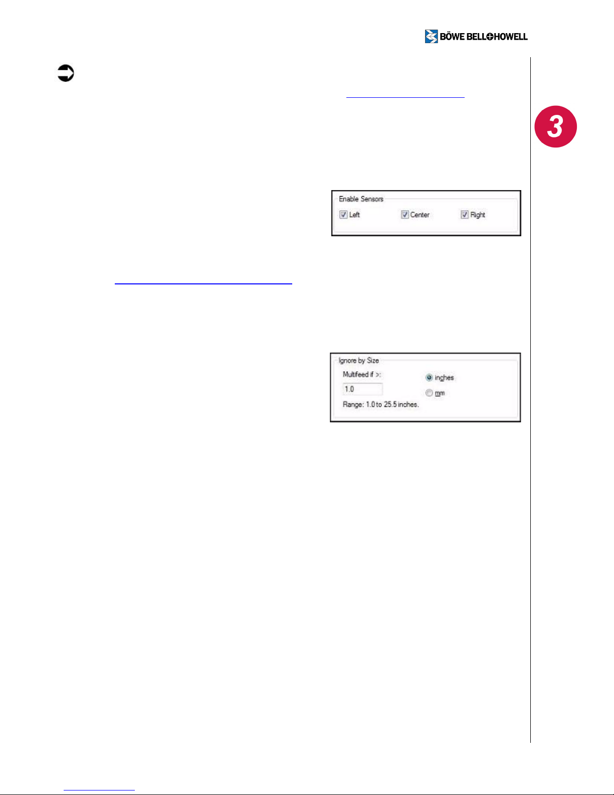
NOTE
If the scanner’s audio feature has been set to Mute (see ”2.2.3.4 Audio” on page 38), the
multifeed alarm that occurs with the Notify and Stop options will not be audible to the
Operator.
3.2.1.2 Enable Sensors
The Enable Sensors control allows the Operator to
enable or disable three individual sensors that, when
enabled, assist in triggering a multifeed alarm. The
three sensors are: Left, Center, and Right.
One or more of these three sensors can be disabled at any given time; however, if all three are
disabled, the Enable Sensors control grays out (becomes inactive) and the Multifeed Mode
control (see ”3.2.1.1
Multifeed Mode” on page 46) automatically sets itself to Off.
3.2.1.3 Ignore by Size
The Ignore by Size control allows the Operator to set
the maximum size of a multifeed that will NOT trigger a
multifeed error when scanning.
This is used to scan documents with labels (often
barcodes) or stickers (mailing labels), documents with
taped photographs or receipts - all while still having
multifeed detection active.
Advanced Features
The Ignore by Size parameter can be set in inches or millimeters (mm), with a range of 1.0 to 25.5
inches (25-647 mm). The default setting for this control is 1.0 inch (25 mm).
S008769 Rev A 47
Page 60

3.2.2 Document Setup Screen
The Advanced Properties Document Setup screen
contains the following controls: Document Types;
Allow Large Skew; Very Long Documents; Ignore
Holes/Ragged Edges; and Front/Back Negative
Image Enable.
3.2.2.1 Document Types
The Document Types area allows the Operator to
invoke changes in speed, feeding, etc., to
accommodate the needs of various document
types.
Using the drop down menu, the Operator can
choose the following:
• Normal - Standard document types - top transport speed, full
performance mode
• Fragile/Difficult - Lower transport speed - useful for delicate
documents that can easily tear
• Thick or Envelope - Thick paper or envelopes
• Tri-Fold - Tri-fold documents
N
OTE
Document types other than ‘Normal’ may under some circumstances reduce scanner speed.
3.2.2.2 Allow Large Skew
If enabled (box checked), the Allow Large Skew control maximizes image data capture for
documents that are fed into the scanner at a non-parallel angle (highly skewed), helping to
eliminate clipped or missing corners. Auto Orientation and Deskew options are then applied to
the entire image in order to adjust image orientation.
3.2.2.3 Very Long Document
When enabled (box checked), the Very Long Document control adjusts the scanner’s transport
speed in order that the scanner along with the software is able to segment a long document (more
Ngenuity Operator Manual
than 40 inches (1016 mm) in length) being scanned into individual images. The size of the
images is determined by the Paper Size setting in the scanning application.
48 S008769 Rev A
Page 61

The Very Long Document control does not support the simultaneous use of some of the other
controls offered through VRS ImageControls and Direct Drivers. Below is a table that identifies
those other controls as well as how the scanner and software handles the conflict when an
Operator attempts to use them together.
Conflicting Controls Resolution
Single Page Scan The scan is terminated and an error message is displayed. The
Very Long Document control is not supported with single page
scanning. Use the batch scan command.
VRS Administration Utility Warning Tab
On Errors QC Mode The document is scanned ignoring the On Errors QC Mode options
Every Page QC Mode The scan is terminated and an error message is displayed. The
First Page QC Mode The scan is terminated and an error message is displayed. The
Deskew and Auto Crop The document is scanned ignoring the Deskew and Auto Crop
Image Rotation of 90, 180, or
270 degrees
Auto Orientation The scan is terminated and an error message is displayed. For
The document is scanned ignoring the warning conditions that are
set. No error message is displayed.
that are set. No error message is displayed.
Very Long Document control is not supported with single page
scanning.
Very Long Document control is not supported with single page
scanning.
options that are set. No error message is displayed.
Do not select rotation options if scanning using the Very Long
Document control.
best results, do not use the Very Long Document control and the
Auto Orientation control at the same time.
Advanced Features
Picking Rectangle For best results, do not use the Very Long Document control and
the Picking Rectangle control at the same time.
Automatic Color Detection For best results, do not use the Very Long Document control and
the Automatic Color Detection control at the same time.
Advanced Clarity For best results, do not use the Very Long Document control and
the Advanced Clarity control at the same time.
3.2.2.4 Ignore Holes/Ragged Edges
The Ignore Holes/Ragged Edges control allows the
Operator to adjust the entry and exit sensors so that they
ignore holes on the leading or trailing edge of a document
(e.g. three-hole punched paper), that may cause the
scanner to detect false starting or trailing edges of a
document.
S008769 Rev A 49
Page 62

The parameter can be set using a measurement in inches or millimeters (mm) with a range of 0.0
to 1.7 inches (0 to 43 mm). Set the parameter to a width just slightly larger than the holes in the
paper (or whatever may be causing the false detection of the leading or trailing edges of a
document).
To activate or enable the Ignore Holes/Ragged Edges control, click the box next to the word
“Enable” (see image).
N
OTE
Enabling the Ignore Holes/Ragged Edges control may reduce scanning speed.
3.2.2.5 Front/Back Negative Image Enable
The controls to enable Front and/or Back Negative Image allow the Operator to request an
inverted or negative bitonal/grayscale image when scanning in black and white or grayscale only.
This control is not supported when scanning in color.
3.2.3 Advanced Color Screen
The Camera Modes control and Camera Gamma
control reside in the Advanced Color screen. The
available options for Camera Modes are: sRGB;
ICC; and Gamma.
• sRGB - uses specific camera gamma to achieve
the best approximation of sRGB color response
N
OTE
This setting applies to the camera output only;
any post-capture image processing settings
affect the final output file’s color content.
• ICC - Select this option to set up scanner
cameras to be compatible with the scanner’s
ICC color correction profile and to cause VRS to
embed ICC-compatible profile data into the image file
ICC profile data is used by some viewing or printing applications to compensate or adjust colors for optimal quality. ICC data is useful only for applications that are ICC-profile aware.
N
Ngenuity Operator Manual
50 S008769 Rev A
OTE
BBH recommends that other post-processing color adjustments NOT be used in combination
with ICC profile mode enabled as these color adjustments can conflict with how the ICC data
is used by an ICC-aware application.
Page 63

For the ICC profile data to be successfully embedded, the scanning application must:
- Be an ImageControls, Direct ISIS or Direct TWAIN application
- Be set up for color scanning
- Be set up to store TIFF, JPEG, or PDF image file types
- Not use VRS Automatic Color Detection (images may be converted to black and white)
To properly view the images, the viewing application must be ICC-profile aware.
N
OTE
Direct ISIS and TWAIN drivers compatible with Ngenuity scanners will be available at a later
date. Please go to the BBH web site (www.bbhscanners.com
ISIS and TWAIN driver availability.
• Gamma (default) - uses a specific camera gamma (1.0 - 2.5) as specified by the Operator.
The camera gamma value is either typed in or selected by moving the slider to the desired
value.
Select a lower gamma value to enhance color saturation for bright colors and a higher gamma
value to enhance color variations for dark colors.
) to check for updates as to direct
Advanced Features
For most documents, BBH recommends the camera gamma be kept at the default value of
1.3.
Selecting one of these Camera Mode options activates that option for both the front and back
camera.
S008769 Rev A 51
Page 64

Ngenuity Operator Manual
52 S008769 Rev A
Page 65

Scanner Options
This section identifies Ngenuity scanners’ two available options: Imprinters (front and back); and
SCSI connection type.
4.1 Imprinter
Both front page (pre-scan) and/or back page (post scan) imprinters are available for purchase to
use with Ngenuity scanners. These user-installable imprinters (same model/part number used for
front page and back page) include a circuit board that controls an ink-jet print head that imprints a
string of alphanumeric characters on documents as they pass through the scanner’s transport.
N
OTE
To purchase an Ngenuity Imprinter Kit, contact BBH Sales at 1-800-SCAN-494, go to the BBH
web store
available on the BBH web site - www.bbscanners.com
initial launch of the Ngenuity scanner.
, or contact a BBH Authorized Spare Parts Reseller (ASPR). A list of ASPRs is
. Imprinter kits will be available after the
Scanner Options
The same imprinter is used for both the front page (pre-scan) and back page (post-scan)
imprinting; therefore, there is only one imprinter kit (part number: ACC1300).
For imprinter Installation and Operating instructions, see Appendix A (to be included in Rev B
and newer of this manual).
4.2 SCSI Connection
The Ngenuity scanner is equipped to accommodate a SCSI connection for communication
between the scanner and host PC. The optional SCSI connection can be used in lieu of the
standard USB connection.
N
OTE
The SCSI and USB connection types cannot be used simultaneously.
To use a SCSI connection, a SCSI card and cable is required. BBH does not provide a SCSI card
or cable with the Ngenuity scanner; therefore, these items must be purchased separately. A
SCSI connection kit is not available through BBH; however, BBH has certified that Adaptec’s
29160 LP or regular profile card is compatible with Ngenuity scanners. The SCSI cable must be a
D68-pin SCSI-3 cable.
S008769 Rev A 53
Page 66

4.2.1 Installation
The following are instructions for installation of an Ngenuity scanner using a SCSI connection
type. These instructions must be followed in the order they appear:
To install and connect using a SCSI device, perform the following:
1. Follow the instructions found in the Ngenuity Quick Install Guide (S008842), taking care to follow the published safety and environmental guidelines (see ”1.2
and ”1.3
Operating Environment” on page 3 in this manual)
Safety Guidelines” on page 1
Keep the original packing material (see ”1.5
ARNING
W
The scanner weighs approximately 112 pounds (51 kg). Be sure to incorporate the appropriate
manpower (taking into consideration your lifting capabilities) before moving or lifting the
scanner.
2. Do NOT connect the scanner to the host PC. Power on the host PC and load the Ngenuity
VRS Professional software provided on the Ngenuity Installation Resource CD-ROM (do NOT
reboot the host PC after the installation)
3. Load the Ngenuity Operator Utility (NOU) on the host PC (do NOT reboot the host PC after
the installation, nor attempt to launch the NOU)
4. Power down the host PC and remove the power cord from the back of it
5. Install the SCSI card (Adaptec 29160) in the host PC
6. Connect the host PC to the scanner
7. Connect power to the scanner and reconnect power to the host PC
8. Power ON the scanner and wait for the initialization sequence to complete
9. Power on the host PC
Unpacking/Repacking” on page 12)
10. Run through the New Hardware Found wizard
11. Launch the NOU by double clicking on the application’s icon found on the host PC’s
Desktop
The NOU’s Home Screen (default) will update once all
the scanner self tests have passed and communication with the scanner has been established. The
installation is complete!
If the NOU failed to connect with the scanner, refer to
”4.2.2
Troubleshooting” on page 55 for information.
Ngenuity Operator Manual
54 S008769 Rev A
Page 67

4.2.2 Troubleshooting
The following steps should be taken if communication cannot be established between the host PC
and the scanner using a SCSI connection.
Verify cable connection and initialization sequence is correct
1. Power OFF the scanner (see 1.4.2 Scanner Back, “
2. Power down the host PC
3. Confirm the SCSI cable is securely connected to the host PC and the scanner
4. Power ON the scanner and wait for the scanner’s initialization sequence to finish completely
5. Power up the host PC
6. Verify communication between the host PC and the scanner is established (see procedure
step 11 under ”4.2.1
Verify the cable and connectors are not damaged
1. Power OFF the scanner (see 1.4.2 Scanner Back, “
2. Power down the host PC
3. Remove the SCSI cable from the host PC and the back of the scanner
4. View the connectors on the SCSI cable, host PC, and scanner. Bent pins or damaged connectors could result in communication not being established and require the replacement of
the SCSI cable, SCSI card that resides in the host PC, or the scanner controller board
Installation” on page 54)
.
.
Power Switch” on page 11)
Power Switch” on page 11)
Scanner Options
5. If the SCSI cable contains bent pins, replace the cable
a. Before reconnecting the new cable, make sure there are no damaged connectors on the
SCSI card that resides in the host PC or the connector found on the back of the scanner
b. If there is no damage, gently connect the new cable
c. If damage is found on the connectors of the SCSI card that resides in the host PC, replace
the card and ensure that the original SCSI cable that was also damaged is not re-used
d. If damage is found on the connectors of the scanner controller board (back of scanner), the
scanner controller board may need to be replaced. Replacement of the scanner controller
board requires a BBH Authorized Service Provider (ASP). A list of BBH ASPs can be found
on the BBH web site at: www.bbhscanners.com
6. Power ON the scanner and wait for the scanner’s initialization sequence to finish completely
7. Power up the host PC
8. Verify communication between the host PC and the scanner is established (see procedure
step 11 under ”4.2.1
If neither of the above troubleshooting tips results in communication being established between
the scanner and the host PC, contact your local BBH ASP. A list of ASPs can be found on the
BBH web site: www.bbhscanners.com
Installation” on page 54)
.
S008769 Rev A 55
Page 68

Ngenuity Operator Manual
56 S008769 Rev A
Page 69

Maintenance
Keeping the scanner’s hardware and software versions current, along with performing routine
maintenance such as cleaning and replacing worn parts, will ensure optimal image quality and
prolong the life of your scanner.
5.1 Version Numbers
To maintain optimal scanner performance and image quality, it is important to make sure the
scanner is being operated using the most current versions of software and firmware that are
available for it.
C
AUTION
Use only firmware and/or software received from BÖWE BELL + HOWELL Scanners (BBH).
Firmware and/or software obtained from other sources are not BBH certified to work with
Ngenuity scanners; therefore, serious functional issues may arise. BBH will not support
firmware and/or software that is obtained from resources other than BBH.
Maintenance
To view the version numbers found on your scanner, go to the Details section of ”2.2.1.1 Menu -
Scanner” on page 31, in this manual for more information.
Current software version information can be obtained by visiting our web site at
www.bbhscanners.com
the BBH Help Desk at 1-800-SCAN-495, or by contacting your local BBH Authorized Service
Provider (ASP) - a list of ASPs can be found on the BBH web site at www.bbhscanners.com
. Scanner firmware version information can be obtained by contacting the
.
5.1.1 Update Firmware
Updating your scanner firmware requires a BBH Authorized Service Provider (ASP). For a list of
BBH ASPs, go to the BBH web site at www.bbhscanners.com
.
5.2 Maintenance Schedule
Ngenuity scanners allow the Operator to easily follow the BBH recommended maintenance
schedule through the use of the Maintenance monitor found in the NOU
”2.2.2.3
Maintenance Monitor” on page 35).
(see
S008769 Rev A 57
Page 70

Once the intervals are set, the Maintenance monitor will display reminders for the Operator on the
host PC as to when scanner maintenance will be, or is required (for more information on setting
maintenance reminders in the Maintenance screen, see ”2.2.4.2
Configure Maintenance
Reminders” on page 41).
Based on the intervals set, and in addition to the reminders displayed by the NOU, the
Maintenance LED (see ”2.1.1.3
Maintenance LED” on page 19) on the scanner’s control panel
will also light, acting as additional notification to the Operator.
To turn the MAINTENANCE LED off and to reset the interval count so future reminders will
display, the Operator must perform a quick confirmation in the NOU after each maintenance
procedure is completed. Instructions on how to do this accompany the instructions for each
maintenance procedure documented within this section.
Below is a table that contains the BBH recommended schedule for performing basic yet important
maintenance functions, along with symptoms that signify maintenance is required. If a symptom
is occurring and the Maintenance Reminder set in the NOU has not yet been triggered, the
interval for the Maintenance Reminder should be adjusted accordingly.
The environment the scanner is operated in, along with the type of documents and volume of
documents being scanned, may require that some of these procedures be performed more
frequently. The Range column defines the range of different settings the Operator can specify in
the Maintenance screen of the NOU if something other than the Recommended setting is needed:
Maintenance Recommended Range Symptoms
Clean Feed Rollers (Pick, Drive,
and Separator Rollers)
Clean Transport Rollers 50,000 pages 5K - 100K
Clean Optics (glass flats, cameras glass covers, sensors)
10,000 pages 1K - 50K
50,000 pages 5K - 150K
CAUTION
For Ngenuity scanners,
the label ‘Optics’ does
NOT include lamps. The
lamps (LEDs) on Ngenuity
scanners should NOT be
cleaned or wiped with any
type of wipes and/or
solvent
Ngenuity Operator Manual
Camera Calibration Every 1200 hours n/a
(factory set)
- Skewed documents
- Multifeeds
- Feeder jams
- Multifeeds
- Transport jams
- Elongated images
Glass Covers / Flats
- Streaks in the image
- Reduced OCR/ICR/Barcode recognition rates
- Blurred images
Page Sensors
- Entry/exit sensor errors
Feeder Sensors
- Feed table doesn’t lower
when out of paper
Poor color image quality (e.g.
white tinted green, red, or
blue)
58 S008769 Rev A
Page 71

Maintenance Recommended Range Symptoms
- Noticeably worn rollers
- Page skewing, multifeeds
Replace Feed Rollers 600,000 pages 100K - 900K
Approx. 34,000
pages (can vary
Ink Cartridge(s) - only relevant if
optional imprinter(s) installed
depending on
number of char-
acters per page
and font used,
etc.)
n/a
(factory set)
and paper jams continue to
occur after cleaning is
performed
Poor print quality
5.2.1 Items Needed
The following items are required for performing routine maintenance on your Ngenuity scanner:
• Ngenuity Roller Kit
• Ngenuity Cleaning Kit
Maintenance
-Blower Brush
- Transport Cleaning Sheets
- Roller and Glass Cleaner (to be used on transport rollers and glass items only)
- Lint-free Cleaning Cloths
- Cleaning Wipes (to be used on skimmer and separator rollers only)
- Swabs
N
OTE
Ngenuity scanners use their own Roller and Cleaning kits. The items contained therein are
specific to Ngenuity scanners. To purchase a Ngenuity Roller or Cleaning Kit, go to our online store at www.bbhscanners.com
available for purchase through BBH Authorized Service Providers (ASPs), and Authorized
Spare Parts Resellers (ASPRs). A list of ASPs and ASPRs is available at
www.bbhscanners.com
.
or call BBH Sales at 1-800-SCAN-494. Kits are also
5.3 Maintenance Procedures
The maintenance procedures documented in the following sections should be performed
following the BBH recommended time intervals or sooner if necessary (see ”5.2
Schedule” on page 57 above).
S008769 Rev A 59
Maintenance
Page 72

Should you have any questions about the following procedures, please contact the BBH Help
Desk at 1-800-SCAN-495. Questions about cleaning supplies and kits should be directed
Scanner Sales at 1-800-SCAN-494.
W
ARNING
Before performing any maintenance procedures, power OFF the scanner.
WARNING
Before performing any maintenance procedures on the scanner, remove all jewelry or any
items from hands or wrists that could become caught on internal scanner components.
5.3.1 Feed Rollers
The Skimmer (Pick and Drive) and Separator Rollers make up what is referred to as the Feed
Rollers.
All Feed Rollers should be cleaned and/or replaced at the same time to ensure optimal scanner
function. Maintenance reminder intervals (both cleaning and replacing) are based on all Feed
Rollers having the same life cycle (see ”2.2.4.2
Configure Maintenance Reminders” on page 41).
5.3.1.1 Skimmer Rollers
The skimmer module is comprised of two rollers; the pick roller and the drive roller (same part
number). Both rollers contain two, removable rubber tires (four total). One outer edge of each tire
contains at least 3 markers. These markers are used as a point of reference for correctly
installing the tires on the roller and also the rollers into the skimmer housing. If the tires are
installed incorrectly or the rollers installed in the skimmer housing incorrectly, the skimmer module
will not function properly.
If replacing tires, all four tires should be replaced at the same time. When replacing tires, also
replace the separator roller (see “
Replacing the Separator Roller” on page 67).
Ngenuity Operator Manual
60 S008769 Rev A
Page 73

.
Transport Cover Open
(view from front)
Pick Roller
Skimmer
Assembly
Tire Tire
Pick Roller
Release Lever (blue)
Maintenance
Drive Roller
Tire Tire
Right Drive Roller
Shaft (spring loaded)
CLEANING THE SKIMMER ROLLERS
Over time the tires on the skimmer rollers (pick and drive rollers) will become dirty and may begin
to slip on paper or cause multifeeds. To prevent feeding problems and avoid rubber tire
replacements, BBH recommends cleaning the skimmer rollers (tires) every 10,000 pages fed or
as needed. Different document types, the condition of the documents being scanned, and the
volume of scanning may require more frequent cleanings.
Always remove the rollers from the scanner for cleaning to ensure best results.
Item(s) Needed
• Cleaning Wipes
To clean the skimmer rollers, perform the following:
1. Power OFF the scanner (see 1.4.2 Scanner Back, “
Power Switch” on page 11)
2. Open the scanner’s transport cover (see 1.4.1 Scanner Front, “
and “
Transport Cover Release Levers” on page 7)
3. Remove the pick roller
- Hold the pick roller with your left hand
- With your right thumb, flip the blue pick roller release lever up towards the top of the scan-
ner so that the lever clears the pick roller and the roller can be moved all the way to the far
right (as viewed from the front of the scanner).
- Once in the far right position, the left side of the pick roller should clear the left gear shaft
and can be lifted out and away from the scanner (note
swings out and away from the scanner for easier removal and replacement of the roller)
S008769 Rev A 61
Transport Cover” on page 7
- the pick roller’s right roller shaft
Page 74

4. Using the Cleaning Wipe, scrub the roller tires in a side to side
(<------->) motion, taking care to rotate the roller, cleaning the
entire surface. Re-install the clean pick roller back into the scanner
- With the pick roller positioned so that the markers located on
the end of the roller tires are visible on the left side, slide the
roller onto the right pick roller shaft (note
- if the pick roller is
installed with the markers (red dots) on the wrong side, the
Markers on
Left Side
roller/skimmer will not function properly)
- Angle the left side down or back towards the skimmer housing and then all the way left,
onto the left pick roller shaft (note
- the right side of the roller should now be clear of the
pick roller release lever)
- Bring the pick roller release lever down over the roller shaft and lock (snap) into place,
securing the pick roller
5. Remove the drive roller
- Position the index finger of your left hand on the left side of the drive roller. Push the roller
as far right as possible and hold it there
- The right drive roller shaft which works on a spring, will shift along with the roller and pro-
trude out of the right side of the scanner’s upper tray. Position the index finger of your
right hand on the area of the drive roller shaft that is protruding out from the right side of
the scanner’s upper tray and hold the shaft there, in place
Left Drive
Roller Shaft
Drive Roller in
far right position
(must be held
there...)
- While holding the right drive roller shaft in place, grasp the entire drive roller with your left
hand, ease it off of the remaining part of the right drive roller shaft, and remove it from the
scanner
- Slowly remove your right index finger from the right drive roller shaft, easing it back into its
fully engaged position
Ngenuity Operator Manual
Right Drive
Roller Shaft
(extended)
62 S008769 Rev A
Page 75

6. Using the Cleaning Wipes, scrub the drive roller tires in a side to
side (<------->) motion taking care to rotate the roller, cleaning
the entire surface of the tires
7. Re-install the clean, drive roller back into the scanner
- Hold the back drive roller between your thumb and index
finger of your left hand with the markers on the roller tires
visible on the left side (note
markers on the wrong side, the roller/skimmer will not
function properly)
- Angle the right side of the drive roller onto the right drive roller shaft. Push the roller onto
the shaft and push the roller and shaft far enough to the right so that the left side of the
roller can be positioned onto the left drive roller shaft
- Once the left side of the drive roller is properly aligned onto the left drive roller shaft, allow
the spring action of the right drive roller shaft to push the drive roller into place
- if the roller is installed with the
Markers on
Left Side
Maintenance
8. After cleaning both skimmer rollers, clean the separator roller (see “
Roller” on page 66)
9. Close the scanner’s transport cover
10. Once both the skimmer rollers and separator
rollers are cleaned, reset the maintenance
reminder for cleaning the Feed Rollers located in
the Maintenance Monitor section of the NOU’s
Home Screen
- With the NOU active and communicating with
the scanner (see ”2.2
Utility” on page 29), click on the Clean
hyperlink associated with “Clean Feed
Rollers” in the Maintenance monitor of the
Home screen
- A confirmation dialog window will display.
Confirm the Feed Rollers have been cleaned
by clicking the YES button. This will reset the
reminder to begin monitoring for the next
required maintenance session
Ngenuity Operator
Cleaning the Separator
With proper cleaning, BBH estimates the tire life of each skimmer roller (pick and drive) to equate
to approximately 600,000 pages fed. Different document types, the condition of the documents
being scanned, and the volume of scanning may alter that number slightly.
If replacing tires, all four tires should be replaced at the same time. When replacing tires, also
replace the separator roller (see “
S008769 Rev A 63
REPLACING TIRES
Replacing the Separator Roller” on page 67).
Page 76

To replace the pick and drive roller tires, perform the following:
1. Power OFF the scanner (see 1.4.2 Scanner Back, “
2. Open the scanner’s transport cover (see 1.4.1 Scanner Front, “
Transport Cover Release Levers” on page 7)
and “
3. Remove the skimmer rollers (see “Cleaning the Skimmer Rollers” on page 61)
4. With the skimmer rollers removed, make note of the position the old tires are in, i.e. what side
the markers are on (in the image, the markers are red in color)
- Work the old tires off of the shaft with your fingers, leaving the
shaft in the same position as a reference for putting on the
new tires
- Another point of reference for correctly installing the tires is:
the side of the tire containing the markers should also be on
the same side that the metal clutch of the roller is visible on
(the opposite side of the roller shaft contains a plastic bushing) - this applies for both tires for each roller (drive and pick)
5. Dispose of the old tires
6. Install new tires with tire markers facing the same side the metal clutch is visible on, taking
care to position the tires flush against the inside lip of the plastic hub
7. Install the skimmer rollers (see “
8. Replace the separator roller (see “
Cleaning the Skimmer Rollers” on page 61)
Replacing the Separator Roller” on page 67)
Power Switch” on page 11)
Transport Cover” on page 7
9. Close the scanner’s transport cover
10. Once all four tires and separator roller have been
replaced, reset the maintenance reminder for
replacing the Feed Rollers located in the
Maintenance Monitor section of the NOU’s Home
Screen
- With the NOU active and communicating with
the scanner (see ”2.2
Utility” on page 29), click on the Replace
hyperlink associated with “Replace Feed
Rollers” in the Maintenance monitor of the
Home screen
- A confirmation dialog window will display.
Confirm the Feed Rollers have been replaced
by clicking the YES button. This will reset the
reminder to begin monitoring for the next
required maintenance session
Ngenuity Operator
Ngenuity Operator Manual
64 S008769 Rev A
Page 77

5.3.1.2 Separator Roller
The separator roller is comprised of one separator brake assembly-1, one roller-2, two o-rings-3,
and two spacers-4.
OTE
N
Unlike the drive and pick rollers, the separator roller does not include replaceable tires.
Maintenance
Exploded View
4
3
2
1
3
4
Assembled View
The separator roller sits on a spring-loaded pivot assembly inside the scanner and is accessed
through the separator door. The separator door is hinged at the bottom near the feeder tray and
opens outward towards the font of the scanner to expose the separator roller. The scanner’s
transport cover must be opened in order to open the separator door.
Bottom or
Back Page
Tray
Separator
Door
Separator Roller
S008769 Rev A 65
Feeder Table
Page 78
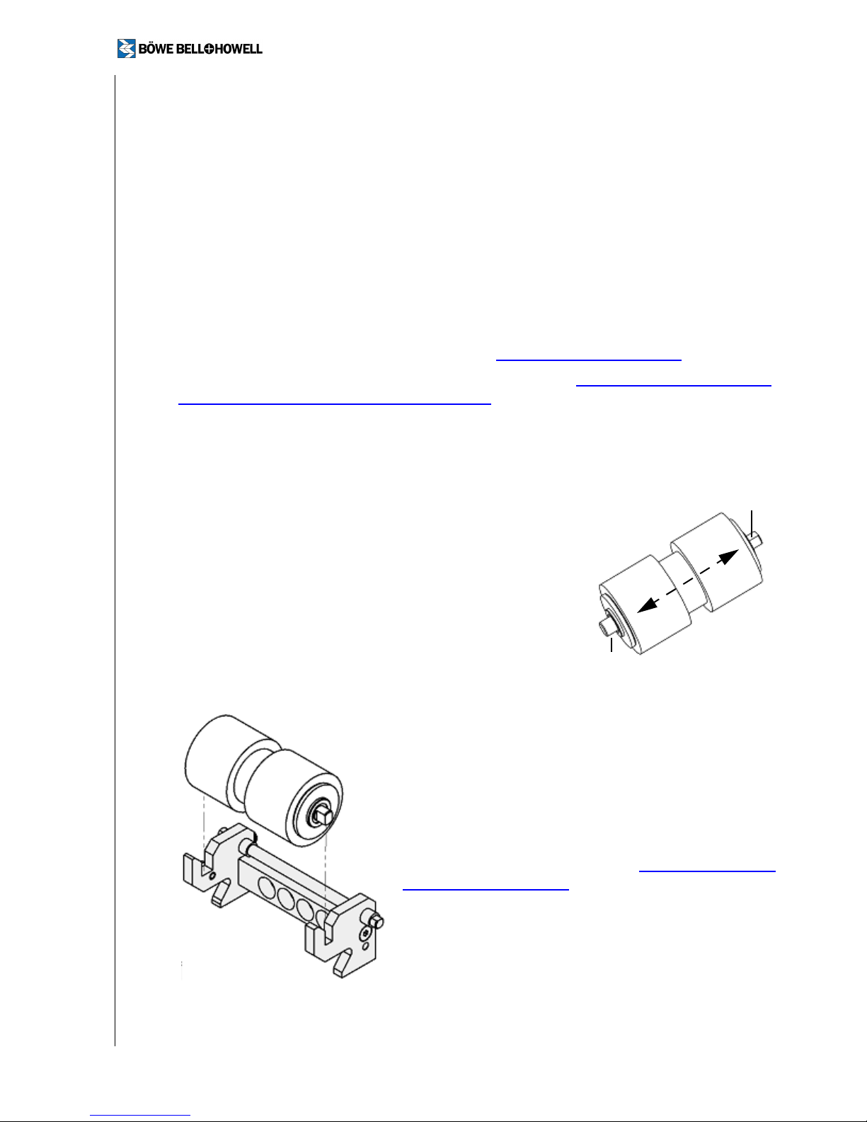
CLEANING THE SEPARATOR ROLLER
Over time the separator roller will become dirty and may begin to cause multifeeds. To prevent
feeding problems, BBH recommends cleaning the separator roller every 10,000 pages fed or as
needed. Different document types, the condition of the documents being scanned, and the
volume of scanning may require more frequent cleanings.
Always remove the separator roller from the scanner for cleaning to ensure best results.
Item(s) Needed
• Cleaning Wipes
To clean the separator roller, perform the following:
1. Power OFF the scanner (see 1.4.2 Scanner Back, “
2. Open the scanner’s transport cover (see 1.4.1 Scanner Front, “
and “
Transport Cover Release Levers” on page 7)
3. Open the separator roller door by pulling the door towards the front of the scanner, exposing
the separator roller
4. Lift the separator roller out of the scanner
5. Using the Cleaning Wipes, scrub the separator roller in a side
to side (<------->) motion, taking care to rotate the roller, cleaning the entire surface
6. Install the clean, separator roller back into the scanner
- Hold open the separator door
- Note the two ends of the separator roller, particularly the
shaft that protrudes from each side; one is flat, the other
rounded. Position the separator roller so that the flat end
is on the right side (as viewed from the front of the scanner)
-Place the roller so that the shaft on each side of the
roller rests within the slots in the pivot assembly (pivot
assembly is stationary inside the scanner), taking care
that the flat end of the shaft on the right side sits flush
within the plastic bracket.
Power Switch” on page 11)
Transport Cover” on page 7
Flat end
Round end
Ngenuity Operator Manual
66 S008769 Rev A
-Close the separator door to confirm the proper
placement of the separator roller
7. Clean the skimmer rollers (see “
mer Rollers” on page 61)
Cleaning the Skim-
Page 79

8. Once the separator roller and the skimmer rollers have been cleaned, reset the maintenance
reminder for cleaning the Feed Rollers located in the Maintenance Monitor section of the
NOU’s Home Screen
- With the NOU active and communicating with
the scanner (see ”2.2
Utility” on page 29), click on the Replace
hyperlink associated with “Clean Feed
Rollers” in the Maintenance monitor of the
Home screen
- A confirmation dialog window will display.
Confirm the Feed Rollers have been cleaned
by clicking the YES button. This will reset the
reminder to begin monitoring for the next
required maintenance session
Ngenuity Operator
REPLACING THE SEPARATOR ROLLER
Maintenance
With proper cleaning, BBH estimates the life of the separator roller to equate to approximately
600,000 pages fed. Different document types, the condition of the documents being scanned,
and the volume of scanning may alter that number slightly.
For optimal performance, if having to replace the separator roller, replace the tires of the skimmer
rollers (pick and drive - 4 tires total) at the same time (see 5.3.1 Feed Rollers, “
on page 63).
To replace the separator roller, perform the following:
1. Power OFF the scanner (see 1.4.2 Scanner Back, “
2. Open the scanner’s transport cover (see 1.4.1 Scanner Front, “
Transport Cover Release Levers” on page 7)
and “
3. Remove the separator roller (see “Cleaning the Separator Roller” on page 66)
4. Remove the roller itself from the rest of the assembly as shown in the Exploded View image
of the separator roller found under ”5.3.1.2
5. Reassemble the components using a new roller, duplicating the assembly shown in the
Exploded View image of the separator roller found under ”5.3.1.2
page 65
6. Reinstall the separator roller into the scanner (see “Cleaning the Separator Roller” on
page 66)
Separator Roller” on page 65
Power Switch” on page 11)
Transport Cover” on page 7
Separator Roller” on
Replacing Tires”
7. Discard the old roller
S008769 Rev A 67
Page 80

8. After replacing the separator roller, replace the skimmer roller tires (4 total) (see 5.3.1 Feed
Rollers, “
9. Once the separator roller and all four skimmer
roller tires have been replaced, reset the
maintenance reminder for replacing the Feed
Rollers located in the Maintenance Monitor
section of the NOU’s Home Screen
- With the NOU active and communicating with
- A confirmation dialog window will display.
Replacing Tires” on page 63))
the scanner (see ”2.2
Utility” on page 29), click on the Replace
hyperlink associated with “Replace Feed
Rollers” in the Maintenance monitor of the
Home screen
Confirm the feed rollers have been replaced
by clicking the YES button. This will reset the
reminder to begin monitoring for the next
required maintenance session
Ngenuity Operator
5.3.2 Optics
Glass Flats, Cameras’ Glass Covers, and Sensors are the scanner components that make up the
group known as the “Optics” for maintenance purposes. BBH recommends that for optimal
performance, the scanner’s Optics should be cleaned as a group, i.e. at the same time. If one
component is to be cleaned, then every component that makes up the scanner’s Optics should be
as well.
After all of the components that make up the Optics are cleaned, the Optic’s maintenance
reminder in the NOU needs to be reset (see ”2.2
reminders will display (including the MAINTENANCE LED on the scanner’s control panel).
Instructions on how to do this accompany the instructions for each of the Optics’ maintenance
procedures.
AUTION
C
For Ngenuity scanners, the label ‘Optics’ does NOT include lamps. The lamps (LEDs) on
Ngenuity scanners should NOT be cleaned or wiped with any type of wipes and/or solvent.
Ngenuity Operator Utility” on page 29) so future
5.3.2.1 Glass Flats
There are two glass flats in the Ngenuity scanner; one located in the bottom (back page) transport
tray and one in the top (front page) transport tray. They are securely set inside black, plastic
Ngenuity Operator Manual
frames. When removing a glass flat for cleaning or replacement, the entire assembly (glass flat
and frame) are removed and replaced as one piece.
68 S008769 Rev A
Page 81

The cameras’ glass covers are part of the Optics group (see ”5.3.2 Optics” on page 68 above).
W
ARNING
Never attempt to remove the glass flat from its frame. Doing so can cause the glass flat to
crack or break and could cause injury to the person holding it.
WARNING
Before performing any maintenance procedures, power OFF the scanner.
WARNING
Before performing any maintenance procedures on the scanner, remove all jewelry or any
items from hands or wrists that could become caught on internal scanner components.
CLEANING GLASS FLATS
Over time the glass flats will become dirty with smudges and/or paper dust which can case
streaks in images, reduced OCR/ICR/Barcode recognition rates, blurred images, etc.
Maintenance
To prevent these problems, BBH recommends cleaning the glass flats every 50,000 pages fed or
as needed. Different document types, the condition of the documents being scanned, and the
volume of scanning may require more frequent cleanings.
For best results, remove the glass flats and clean both sides of each.
Item(s) Needed
• Roller and Glass Cleaner
• Lint Free Cloth
C
AUTION
Never spray the Roller and Glass Cleaner into the scanner.
To clean the bottom (back page) glass flat, perform the following:
1. Power OFF the scanner (see 1.4.2 Scanner Back, “
2. Open the scanner’s transport cover (see 1.4.1 Scanner Front, “
and “
Transport Cover Release Levers” on page 7)
3. Remove the bottom (back page) glass flat
Power Switch” on page 11)
Transport Cover” on page 7
S008769 Rev A 69
Page 82

Glass Flat
Fastening Clips (2)
Frame
Guides (5)
Left Side
Right Side
Glass
- Locate the 2 fastening clips that secure the glass flat in the scanner. They are located
along the back, horizontal edge of the glass flat (closest to the back of the scanner), one
on the far left side and the other on the far right. Gently pull the clips with your index finger
towards the front of the scanner to release the glass flat from its position
- Holding the left and right sides of the frame around the glass flat, lift the back half of the
glass flat up and slide the entire assembly towards the back of the scanner to release the
glass flat’s frame from the transport (there are 5 guides attached to the glass flat’s frame
that sit beneath the transport tray)
4. Spray the Roller and Glass Cleaner on the Lint Free Cloth, taking care that any overspray
does not fall inside the scanner
5. Wipe down the both sides of the glass flat, taking care not to touch the cleaned glass with your
fingers
6. Re-insert the cleaned glass flat into the scanner
- Hold the frame of the glass flat on the left and right side so that the fastening clips (2) are
on the back side of the glass flat (side closest to the back of the scanner). Position the
glass flat over the top and slightly behind the opening in the transport tray, centering the
glass flat over the opening
- Slide the guides (5) under the transport tray towards the feeder table
Bottom (back page) Tray - Inserting the Glass Flat
(as viewed from left side)
Back of scanner Front of Scanner
Fastening
Ngenuity Operator Manual
Clips (2)
Glass Flat
70 S008769 Rev A
Five guides slide underneath the transport tray
Page 83

- Ease the back side of the glass flat (side with 2 fastening clips) down into place (the fastening clips should marry up with corresponding indentations in the transport tray)
Tray indentations for glass flat clips
Glass Flat Removed
Bottom (back page) tray as viewed from the top looking down
- Secure the glass flat in place by gently pushing the 2 fastening clips back towards the
back of the scanner until they snap into place
7. Perform the same exercise for the upper (front page) glass flat
8. Clean all the items in the scanner’s Optics group (glass flats, cameras’ glass covers, sensors)
9. Close the scanner’s transport cover
10. Once all the items that make up the scanner’s
Optics have been cleaned, reset the Optics maintenance reminder in the NOU
Maintenance
- With the NOU active and communicating with
the scanner (see ”2.2
Utility” on page 29), click on the Clean
hyperlink associated with “Clean Optics” in the
Maintenance monitor of the Home screen
- A confirmation dialog window will display.
Confirm the Optics have been cleaned by
clicking the YES button. This will reset the
reminder to begin monitoring for future,
required maintenance
Ngenuity Operator
REPLACING GLASS FLATS
Although it is necessary to clean the glass flats on a regular basis, replacing a glass flat is only
required if one becomes scratched or chipped.
To replace a glass flat, perform the following (instructions refer to the bottom (back page)
glass flat):
1. Power OFF the scanner (see 1.4.2 Scanner Back, “
Power Switch” on page 11)
S008769 Rev A 71
Page 84

2. Open the scanner’s transport cover (see 1.4.1 Scanner Front, “Transport Cover” on page 7
and “
Transport Cover Release Levers” on page 7)
3. Remove the bottom (back page) glass flat (see “Cleaning Glass Flats” on page 69)
4. Clean the new, bottom (back page) glass flat (see “
5. Insert the new, bottom (back page) glass flat (see “
Cleaning Glass Flats” on page 69)
Cleaning Glass Flats” on page 69)
5.3.3.2 Cameras’ Glass Covers
The cameras in Ngenuity scanners contain a glass cover (not to be confused with the glass flat)
that protect the camera from dust and paper particles getting inside of it. They are located directly
beneath the glass flats, between and below the LED lamps.
The cameras’ glass covers are part of the Optics group (see ”5.3.2
Bottom or Back Page
Tray (as viewed from
top, left)
Glass flat removed
Back camera’s glass cover
Optics” on page 68).
Bottom or back page
tray
LEDs
AUTION
C
The cameras’ glass covers should never be replaced. Do NOT attempt to remove a camera’s
glass cover. They should be cleaned only.
Ngenuity Operator Manual
Front of scanner
72 S008769 Rev A
Page 85

CLEANING THE CAMERAS’ GLASS COVERS
Dust on the cameras’ glass covers can cause streaks or make images fuzzy; therefore, the glass
covers require cleaning. BBH recommends cleaning the cameras’ glass covers every 50,000
pages fed or as needed. Different document types, the condition of the documents being
scanned, and the volume of scanning may require more frequent cleanings. A good rule of thumb
to follow is, anytime the glass flats are cleaned the cameras’ glass covers should be cleaned at
the same time.
Item(s) Needed
•Swab
To clean the cameras’ glass covers, perform the following (the following instructions pertain
to the back camera’s glass cover):
W
ARNING
Before performing any maintenance procedures, power OFF the scanner.
Maintenance
WARNING
Before performing any maintenance procedures on the scanner, remove all jewelry or any
items from hands or wrists that could become caught on internal scanner components.
1. Power OFF the scanner (see 1.4.2 Scanner Back, “Power Switch” on page 11)
2. Open the scanner’s transport cover (see 1.4.1 Scanner Front, “
Transport Cover Release Levers” on page 7)
and “
Transport Cover” on page 7
3. Remove the bottom (back page) glass flat (see “Cleaning Glass Flats” on page 69)
4. Using a clean dry Swab, gently wipe across the glass cover to remove any accumulated dust
particles
Do not spray any solvent on the Swab, except in the event where the dry Swab will not
remove residue on the glass (e.g. grease, dried liquid, etc.). In the event a solvent is required
to thoroughly clean the camera’s glass cover, use the supplied Glass and Roller cleaner.
C
AUTION
Spray the Glass and Roller cleaner directly on the Swab - NOT IN THE SCANNER. When
spraying the swab, spray the Glass and Roller cleaner away from the inside of the scanner so
as to avoid getting any overspray inside the scanner.
If using a swab moistened with the supplied Glass and Roller cleaner, take care not to wipe the
swab on the LEDs.
Do not re-use Swabs; doing so introduces the dirt from one scanner into another
S008769 Rev A 73
Page 86

5. Once the glass cover is clean, re-insert the glass flat (see “Cleaning Glass Flats” on page 69)
6. Perform the same procedure for the front page camera’s glass cover
7. Clean all the items in the scanner’s Optics group (glass flats, cameras’ glass covers, sensors)
8. Close the scanner’s transport cover
9. Once all the items that make up the scanner’s
Optics have been cleaned, reset the Optics maintenance reminder in the NOU
- With the NOU active and communicating with
the scanner (see ”2.2
Utility” on page 29), click on the Clean
hyperlink associated with “Clean Optics” in the
Maintenance monitor of the Home screen
- A confirmation dialog window will display.
Confirm the Optics have been cleaned by
clicking the YES button. This will reset the
reminder to begin monitoring for future,
required maintenance
Ngenuity Operator
5.3.3.3 Cleaning the Sensors
There are seven sensors on the Ngenuity scanner that will require regular cleaning: the feeder
sensor (1); the gap sensor (1); the page entry sensor (3); the straight pass-through sensor (1);
and the exit sensor (1). The gap, page entry, straight pass-through, and exit sensors are referred
to as the “transport sensors”. BBH recommends cleaning all of these sensors every 50,000
pages fed or as needed. Different document types, the condition of the documents being
scanned, and the volume of scanning may require more frequent cleanings.
The sensors are part of the Optics group (see ”5.3.2
C
AUTION
Avoid using any type of cotton swab or any item that may leave lint behind. These types of
cleaning items can cause further problems with sensors functioning properly.
Use the supplied blower brush to clean these sensors. If problems continue to occur, the use of
forced air (not supplied) may be required to properly clean the sensors.
W
ARNING
Make sure to power OFF the scanner before applying forced air to the sensors.
Optics” on page 68).
Ngenuity Operator Manual
74 S008769 Rev A
Page 87

CAUTION
If using forced air to clean the sensors, do NOT turn the can of forced air upside down or tip it
sideways more than 40 degrees while using. The extension tube can be bent so as to avoid
having to tip the can.
CLEANING THE FEEDER SENSOR
The feeder sensor detects paper on the feeder table. Dust and small particles of paper may build
up on the sensor, causing the feeder table not to lower after the last page fed. Regular cleaning
of the feeder sensor will reduce this problem.
Feeder Sensor
Separator
Roller Door
Cork Pad
Maintenance
Feeder Table
Item(s) Needed
•Blower Brush
• Forced Air (optional, not supplied)
C
AUTION
Avoid using any type of cotton swab or any item that may leave lint behind. These types of
cleaning items can cause further problems with sensors functioning properly.
WARNING
Make sure to power OFF the scanner before applying forced air to the sensors.
S008769 Rev A 75
Page 88

CAUTION
If using forced air to clean the sensors, do NOT turn the can of forced air upside down or tip it
sideways more than 40 degrees while using. The extension tube can be bent so as to avoid
having to tip the can.
To clean the feeder sensor, perform the following:
1. Power OFF the scanner (see 1.4.2 Scanner Back, “
2. Using the supplied blower brush, squeeze the blower brush to push short bursts of air into the
opening for the feeder sensor. At the same time, sweep the brush end down into the opening
of and across the feeder the sensor
3. When finished, open the transport cover (see 1.4.1 Scanner Front, “
page 7 and “Transport Cover Release Levers” on page 7) and clean the remaining sensors
4. Clean all the items in the scanner’s Optics group (glass flats, cameras’ glass covers, sensors)
5. Close the scanner’s transport cover
6. Once all the items that make up the scanner’s
Optics have been cleaned, reset the Optics maintenance reminder in the NOU
- With the NOU active and communicating with
the scanner (see ”2.2
Utility” on page 29), click on the Clean
hyperlink associated with “Clean Optics” in the
Maintenance monitor of the Home screen
- A confirmation dialog window will display.
Confirm the Optics have been cleaned by
clicking the YES button. This will reset the
reminder to begin monitoring for future,
required maintenance
Ngenuity Operator
Power Switch” on page 11)
Transport Cover” on
The transport sensors consist of the gap (1), page entry (3), pass thru (1), and exit (1) sensors.
To view these sensors, open the scanner’s transport cover. All of the transport sensors are
located in the scanner’s top or front page assembly. With the exception of the exit sensor, all the
transport sensors can be viewed by standing in front of the scanner.
To view the exit sensor, move to the right side of the scanner so as to view the very back of the
front transport tray (due to the shape/bend of the front transport tray, the exit sensor actually faces
Ngenuity Operator Manual
the back of the scanner).
76 S008769 Rev A
CLEANING TRANSPORT SENSORS
Page 89

Dust or small pieces of paper may accumulate on these sensors, causing the miss-detection of
the leading or trailing edge of a document, which can cause errors in the scanner. Regular
cleaning of the transport sensors will prevent this from occurring.
ARNING
W
Before performing any maintenance procedures, power OFF the scanner.
WARNING
Before performing any maintenance procedures on the scanner, remove all jewelry or any
items from hands or wrists that could become caught on internal scanner components.
Maintenance
S008769 Rev A 77
Page 90

Top or Front Page Tray Assembly
(as viewed from front - transport cover open)
Pass Thru
Sensor (1)
Gap Sensor (1)
Page Entry
Sensors (3)
Left Side View - Transport Cover Open
Top or Front Page Assembly - Covers Removed
Front of
Scanner
Location of Exit Sensor
View from
bottom right
looking up
Ngenuity Operator Manual
Exit Sensor
T
Transport Cover
Hinge
78 S008769 Rev A
Page 91

Item(s) Needed
•Blower Brush
• Forced Air (optional, not supplied)
C
AUTION
Avoid using any type of cotton swab or any item that may leave lint behind. These types of
cleaning items can cause further problems with sensors functioning properly.
WARNING
Make sure to power OFF the scanner before applying forced air to the sensors.
CAUTION
If using forced air to clean the sensors, do NOT turn the can of forced air upside down or tip it
sideways more than 40 degrees while using. The extension tube can be bent so as to avoid
having to tip the can.
To clean the transport sensor, perform the following:
Maintenance
1. Power OFF the scanner (see 1.4.2 Scanner Back, “
2. Open the scanner’s transport cover (see 1.4.1 Scanner Front, “
and “
Transport Cover Release Levers” on page 7))
3. Using the supplied blower brush, squeeze the blower brush to push short bursts of air into the
opening for the sensors. At the same time, sweep the brush end down into the opening of and
across each of the sensors
4. Clean all the items in the scanner’s Optics group (glass flats, cameras’ glass covers, sensors)
5. Close the scanner’s transport cover
6. Once all the items that make up the scanner’s
Optics have been cleaned, reset the Optics maintenance reminder in the NOU
- With the NOU active and communicating with
the scanner (see ”2.2
Utility” on page 29), click on the Clean
hyperlink associated with “Clean Optics” in the
Maintenance monitor of the Home screen
- A confirmation dialog window will display.
Confirm the Optics have been cleaned by
clicking the YES button. This will reset the
reminder to begin monitoring for future,
required maintenance
Ngenuity Operator
Power Switch” on page 11)
Transport Cover” on page 7
S008769 Rev A 79
Page 92

5.3.4 Camera Calibration
Camera calibration is important for maintaining consistent image quality. Calibrating the cameras
resets the white level and balance, as well as the black level and balance in the scanner. It
performs red, green, blue (RGB) color balance and gain setting, and horizontal light level
correction. The final measurement results in a correction function which levels the brightness
over the complete scan width.
Two white calibration sheets are used for the camera calibration procedure. These sheets are a
part of the camera calibration kit that is included with the scanner. Additional kits can be
purchased from our on-line store at www.bbhscanners.com
494. Kits are also available for purchase through BBH Authorized Service Providers (ASPs), and
Authorized Spare Parts Resellers (ASPRs). A list of ASPs and ASPRs is available at
www.bbhscanners.com
The Ngenuity scanner’s cameras can be calibrated independently or together; however, BBH
strongly recommends that cameras always be calibrated together. The duration of the calibration
process when calibrating both cameras should take approximately 4-7 minutes.
N
OTE
Before calibrating the camera(s), make sure to clean scanner optics to ensure a successful
calibration with the best possible results (see ”5.3.2
.
or call BBH Sales at 1-800-SCAN-
Optics” on page 68).
NOTE
Before calibrating the camera(s), make sure full power is applied to the scanner (not in Sleep
mode) for at least 5 minutes.
Item(s) Needed
• Two, clean camera calibration sheets, free of folds, tears, marks or any other matter that could
cause less than ideal calibration results
To calibrate the cameras, perform the following:
1. Establish communication between the scanner and the NOU (see ”2.2
Utility” on page 29)
2. Within the NOU, click on one of the Calibrate
links found in the Maintenance section of the
NOU’s Home page
Cameras can be calibrated individually; however, BBH strongly recommends that both
cameras always be calibrated at the same
time.
Ngenuity Operator
Ngenuity Operator Manual
80 S008769 Rev A
Page 93

3. Clicking on either one of the Calibrate links (front or back)
will display the Select Cameras screen. From this screen
the user should select the ‘Both’ option for calibrating both
cameras and then click the START button
The prompt to lift the skimmer and manually feed the
calibration sheets into the scanner will display.
Maintenance
4. Lift the skimmer. The scanner will automatically go into manual mode (see “
Manual Mode” on
page 21). The feeder table will rise and the transport will begin to run
5. When the feeder table rises to the full up position, feed the stack of 2 calibration sheets into
the transport in landscape orientation
6. The calibration process begins and the NOU will
display the following dialog
A counter and a progress bar will mark the
progress of the calibration steps.
C
AUTION
Do NOT shut down the scanner while calibration is in progress.
Do NOT open the scanner’s transport cover while calibration is in progress.
Do NOT attempt to shut down the host PC while calibration is in progress.
Do NOT manipulate any software applications on the host PC or other host PC controls while
calibration is in progress.
Performing any of the above mentioned acts during the calibration process could result in
calibration failure.
7. When the calibration function has completed all
steps successfully, a confirmation screen will display. Click the CLOSE button. The calibration
sheets will be automatically ejected from the
scanner
N
OTE
If the confirmation screen states that the calibration was unsuccessful, power OFF the
scanner, shut down the host PC, clean the scanner’s optics and begin the procedure again.
If the calibration is unsuccessful a second time, contact the BBH Help Desk at 1-800-SCAN495 or your local BBH Authorized Service Provider (ASP). A list of ASPs can be found on the
BBH web site at www.bbhscanners.com
S008769 Rev A 81
.
Page 94

5.3.5 Cleaning the Transport
Over time, the transport assembly components will become dirty and may feed documents
erratically or skew the documents as they enter the scanner. To prevent erratic feeding, clean the
transport every 50,000 pages fed or as needed. Different document types, the condition of the
documents being scanned, and the volume of scanning may require more frequent cleanings.
Item(s) Needed
• Transport Cleaning Sheets
N
OTE
BBH recommends cleaning the glass flats after cleaning the transport in the event the
transport cleaning sheets have left any residue on the glass flats which could cause image
issues.
To clean the transport, perform the following:
1. Establish communication between the scanner and the NOU (see ”2.2
Utility” on page 29)
2. Within the NOU, make sure one of the Custom Functions is set to “Feed Test Batch” (see
”2.2.3.3
3. Press the F1 or F2 key on the scanner’s control panel (see ”2.1 Control Panel” on page 17),
depending on which key the Custom Function of “Feed Test Batch” was set to in the NOU
(see ”2.2.3.3
4. Feed one, new transport cleaning sheet into the scanner’s transport (landscape)
5. After it exits the transport, run it through the scanner again
6. Flip the transport cleaning sheet over and run it through two times (repeat steps 4 and 5)
7. Press and hold the PAUSE/STOP button on the scanner’s control panel until the
transport stops running (about 2-3 seconds)
8. Press the CLEAR/RESTART button on the scanner’s control panel
9. Discard the used transport cleaning sheet.
Custom Functions” on page 38)
Custom Functions” on page 38), to start the scanner’s transport
Ngenuity Operator
N
OTE
After cleaning the transport, BBH recommends cleaning both glass flats, as residue from the
Ngenuity Operator Manual
transport cleaning sheets can sometimes come loose and remain on the glass (see
”5.3.2.1
82 S008769 Rev A
Glass Flats” on page 68).
Page 95

5.3.6 Lamps (LEDs)
CAUTION
The LEDs on Ngenuity scanners should NOT be cleaned or wiped with any type of wipes and/
or solvent
NOTE
The LED illumination system on Ngenuity scanners should last the life of the scanner with
normal use. If something happens that requires the replacement of the LEDs, contact the BBH
Help Desk at 1-800-SCAN-495 or your local BBH Authorized Service Provider (ASP). A list of
BBH ASPs can be found on the BBH web site at www.bbhscanners.com
.
5.3.7 Feeder Cork Pad Replacement
The cork pad located on the feeder table should not need cleaning; however, it may wear over
time and require replacement for optimal feeding performance (for more information about the
cork pad, see 1.4.1 Scanner Front - “
Cork Pad” on page 6).
Maintenance
Feeder Sensor
Separator
Roller Door
Cork Pad
Feeder Table
Item(s) Needed
•New cork pad
To replace the cork pad, perform the following:
1. Power OFF the scanner (see 1.4.2 Scanner Back, “
Power Switch” on page 11)
S008769 Rev A 83
Page 96

2. Using a small, flat blade screw driver gently lift the cork pad from the feeder table, taking care
not to scratch the feeder table in the process. Make sure all remnants of the old cork pad are
removed
3. Remove the clear cover from the adhesive strip on the back of the new cork pad
4. Position the new cork pad in the well found on the feeder table and apply gentle, but firm
pressure to assist in securing it to the surface
Ngenuity Operator Manual
84 S008769 Rev A
Page 97

Troubleshooting
The following section offers some helpful hints for troubleshooting your Ngenuity scanner should
the need arise.
Should you have any questions about the information contained within this section, contact the
BBH Help Desk at 1-800-SCAN-495. If your problem(s) persist, contact your local BBH
Authorized Service Provider (ASP). A list of BBH ASPs can be found on our web site at
www.bbhscanners.com
.
6.1 Preliminary Troubleshooting Procedures
Installation/Setup/Connectivity
Symptom Cause Remedy
Found New Hardware wizard
appears when connecting
with USB on a PC that’s
already had communication
established with the scanner
Kofax errors displayed on
host PC when attempting to
install and use the USB
connection with a SCSI card
installed
The USB cable was
unplugged from one port on
the host PC to another after
communication had been
established with the scanner
using the original port.
Presence of the SCSI card
conflicting with the USB
function
Move the USB cable back to the
original port on the host PC or
complete the Found New
Hardware wizard
Uninstall the SCSI card from the
host PC
Troubleshooting
OTE
N
For information on troubleshooting your SCSI connection, see ”4.2.2 Troubleshooting” on
page 55 under ”4.2 SCSI Connection” on page 53 in this manual.
Self Test Error Messages
Error Message Possible Cause Possible Remedy
Feeder Table Fault Can be caused by placing too
Internal Communication Fault The machine control
S008769 Rev A 85
heavy a load on the feeder
table
processor has lost
communication with one or
more of the following:
Imprinters, Sensor Processor,
or the Control Panel
Remove any heavy load and
power cycle the scanner
Service required. Contact your
local BBH Authorized Service
Provider (ASP). A list of ASPs
can be found on the BBH web site
at www.bbhscanners.com
Page 98

Error Message Possible Cause Possible Remedy
Bad or Missing Front Camera The front (top) camera is not
communicating
Bad or Missing Back Camera The back (bottom) camera is
not communicating
Front and/or Back Imprinter
Self Test Failed
Sensor Fault One or more sensors could
Bad or Missing Control Panel
(Front Panel)
An imprinter was detected
and enabled, but is no longer
communicating
not be calibrated
The scanner’s control panel is
not communicating
Service required. Contact your
local BBH Authorized Service
Provider (ASP). A list of ASPs
can be found on the BBH web site
at www.bbhscanners.com
Service required. Contact your
local BBH Authorized Service
Provider (ASP). A list of ASPs
can be found on the BBH web site
at www.bbhscanners.com
Check that the cable is
undamaged and the connector
firmly seated
Check that paper was not left in
the transport at power ON, and
that sensors are clean and not
blocked (see ”5.3.3.3
the Sensors” on page 74)
Service required. Contact your
local BBH Authorized Service
Provider (ASP). A list of ASPs
can be found on the BBH web site
at www.bbhscanners.com
Cleaning
CGA Port Not Responding ... Service required. Contact your
Corrupt or Missing MC
Firmware
... Service required. Contact your
Image and Feeding
Symptom Cause Remedy
Streaks in the image
Reduced bard code
recognition rates
Ngenuity Operator Manual
Blurred images
Glass flat(s) and/or cameras’
glass cover(s) need to be
cleaned
Camera(s) need to be
calibrated
local BBH Authorized Service
Provider (ASP). A list of ASPs
can be found on the BBH web site
at www.bbhscanners.com
local BBH Authorized Service
Provider (ASP). A list of ASPs
can be found on the BBH web site
at www.bbhscanners.com
- Clean the glass flats “
Glass Flats” on page 69
- Clean the cameras’ glass covers
“
Cleaning the Cameras’ Glass
Covers” on page 73
Cleaning
Artifacts in the image
86 S008769 Rev A
- Calibrate the camera(s)
”5.3.4
Camera Calibration” on
page 80
Page 99

Symptom Cause Remedy
Skewed documents
Multifeeds
Feeder jams
Transport jams
Page frame errors
Entry/exit sensor errors Transport sensors need
Feeder table doesn’t
automatically lower after last
page is fed
Image is too dark Camera(s) need to be
Feeder needs cleaning
Skimmer rollers need
cleaning
Transport needs cleaning
Page sensors need cleaning
cleaning
Feeder sensor needs
cleaning
calibrated
Clean the skimmer rollers
“
Cleaning the Skimmer Rollers”
on page 61
Clean the separator roller
“
Cleaning the Separator Roller”
on page 66
Clean the transport area
”5.3.5
Cleaning the Transport” on
page 82
Clean the transport sensors
“
Cleaning Transport Sensors” on
page 76
Clean the transport sensors
“
Cleaning Transport Sensors” on
page 76
Clean the feeder sensor
“
Cleaning the Feeder Sensor” on
page 75
Calibrate the camera(s)
”5.3.4
Camera Calibration” on
page 80
Troubleshooting
Slippage of documents or
multifeeds
Color image lacks fidelity Camera(s) need to be
Scanner throughput has
decreased
Host PC displays a
“Peripheral Malfunction” error
Front skimmer roller (pick
roller) is worn out
Skimmer needs cleaning
calibrated
Tires on skimmer rollers (pick
and drive rollers) installed
incorrectly
Most easily described as a
type of multifeed not handled
by an Autoresolve. Occurs at
the feeding stage of the scan.
VRS catches the error and
communicates with the
scanner that an error
occurred. The scanner quits
feeding documents, but the
transport continues to run
until the automatic timeout of
20 seconds occurs. An error
light does NOT display on the
scanner’s control panel.
Clean and or replace the skimmer
rollers ”5.3.1.1
on page 60
Calibrate the camera(s)
”5.3.4
Camera Calibration” on
page 80
Confirm skimmer rollers (pick and
drive rollers) are installed properly
“
Replacing Tires” on page 63
Click through (resolve) the error
displayed on the Host PC, confirm
last image saved, and rescan
documents beginning with first
document’s image missed (since
one or two documents may get
fed after the error occurs, there
may be multiple images missed).
Skimmer Rollers”
S008769 Rev A 87
Page 100

Symptom Cause Remedy
Dog-earring pages Most common cause is the
straight pass-through door is
not fully or completely closed.
Confirm the straight pass-through
door is fully closed. If problem
persists, contact your local BBH
Authorized Service Provider
(ASP). A list of ASPs can be
found on the BBH web site at
www.bbhscanners.com
Ngenuity Operator Manual
88 S008769 Rev A
 Loading...