

Page 1
KODAK PROFESSIONAL LED II Pr inter 20R
Operator’s Guide Part No. 6B6192
Page 2

© Eastman Kodak Company, 2000
All rights reserved. Contents of this publication may not be reproduced in any form
without permission from Eastman Kodak Company.
Page 3
Regulatory Information
Radio Frequency Interference
The United States (47 CFR Part 15 Subpart B, FCC Class A, EMC)
This equipment has been tested and found to comply with the limits for a Class A
digital device, pursuant to Part 15 of the FCC Rules. These limits are designed to
provide reasonable protection against harmful interference when the equipment is
operated in a commercial environment. This equipment generates, uses, and can
radiate radio frequency energy and, if not installed and used in accordance with
the instruction manual, may cause harmful interference to radio communications.
Operation of this equipment in a residential area is likely to cause harmful
interference in which case the user will be required to correct the interference at
his own expense.
IMPORTANT: Changes or modifications to the product that are not authorized by
Eastman Kodak Company could void the FCC Certification and
negate your authority to operate this product.
Canada (ICES-003 Issue 2 Rev1 Canada, Class A, EMC)
This Class A digital apparatus meets all requirements of the Canadian
Interference-Causing Equipment Regulations.
Cet appareil numerique de la classe A respecte toutes les exigences du
Reglement sur le materiel brouilleur du Canada.
European Union (EU, CE Marking, EMC)
This equipment has been type tested and found to comply with the requirements
for electromagnetic compatibility as established by European Communities
Council Directive 89/336/EEC and Low Voltage Directive (Product Safety)
73/23/EEC.
Japan (VCCI, Class 1 EMC)
The following is a translation of the above statement:
“This equipment is in the Class 1 category (information to be used in commercial
and/or industrial areas. Consequently, when used in a residential area or in an
adjacent area thereto, radio interference may be caused to radios and TV
receivers, etc. Read the instructions for correct handling”.
Page 4

Safety Regulations
IMPORT ANT: This equipment incorporates high-voltage components. Adequate safeguards and interlocks
have been designed into this equipment to reduce the risk of injury during normal operation.
As with any electrical equipment of this kind, adequate ventilation must be provided to
minimize exposure to heat, dust , ozone, and othe r emis sions. The following labels will be
found on the product. The exclamation point symbol (A) indicates that the user should refer
to this guide for safety information. The hot symbol (B) indicates a hot surface area on the
printer that should not be touched. The electrical hazard/shock warning symbol (C)
identifies the possibilit y of electrica l shock inside an area that should only be accessed by
Kodak CES personnel.
CAUTION: Before connecting or disconnecting the SCSI cable or terminator, tur n off the power
for the printer and the host computer. Also, if you replace the SCSI cable, remove the
Ferrite bead from the existing SCSI cable and install it on the new SCSI cable.
Environmental Regulations
IMPORTANT: Always adhere to your local ordinances and regulations for disposal of paper, chemicals,
filters, cleaning supplies, etc.
A B C
Page 5

Warranty Information
The following warranty information pertains to equipment that is installed in the United States
only. For equipm ent installed in countr i es ot he r t han the Uni ted S tates, the terms and conditions
of the new equipment warranty will be provided by the Kodak company in the country in which
the sale is finalized, or by a Kodak-appointed distributor in those countries where Kodak does
not have direct sales representation.
Warranty Period
Kodak warrants new equipment to function properly for 90 days from the date of initial
installation. This warranty covers the purchaser of this equipment as well as anyone else who
owns i t during the warranty period.
Warranty Repair Coverage
If this equipment does not function properly during the warranty period, a Kodak Customer
Equipment Services Field Engineer will repair the equipment without charge during Kodak’s
normal working hours (usually 8:00 a.m. to 5:00 p.m., Monday through Friday). Such repair
service will include any adjustments and/or replacement of parts required to maintain your
equipment in good working order. Supply items are billed as required.
Off-hours services are available at overtime rates.
How to Obtain Service
For techn i cal support, service, repai r and fuse repl ace men t i nfo r mat ion, contact E ast m an Kodak
Company’s Technical Assistance Center at 1-800-822-1414.
Limitations
Warranty Service is limited to areas within Kodak’s established marketing centers in the
contiguous United States, the island of Oahu in Hawaii, and certain areas of Alaska.
This warranty does not cover circumstances beyond Kodak’s control; service or parts for any
attachments, accessories, or alterations not marketed by Kodak, nor to correct problems
resulting from their use.
Damaged caused by failure to meet electrical specifications in this manual will not be covered
under the warranty or service agreement claim.
Damage to the imaging shoe as a result of customer misuse or abuse will not be covered under
the warranty or service agreement claim. Do not use sharp objects to clear paper in this area.
Kodak makes no other warranties, express, implied or of merchantability, for this
equipment.
Repair or repl a cem ent without charge is Kodak’s only obligation under this warranty. Kodak will
not be responsible for any consequential or incidental damages resulting from the sale, use or
improper functioning of this equipment, even if loss or damage is caused by the negligence or
other fault of Kodak.
Such damages, for which Kodak will not be responsible, include, but are not limited to, loss of
revenue of profit, downtime costs, loss of use of the equipment, cost of any substitute
equipment, facilities or services or claims of your customers for such damages.
This limitation of liability will not apply to claims for injury to persons or damage to property
caused by the sole negligence or fault of Kodak or by persons under its direction or control.
Kodak Service Agreements
For information on Kodak Service Agreements, call Kodak Service Marketing Operations
at 1-800-645-6325.
Page 6

Page 7

September 2000 vii
Table Of Contents
About This Guide................................................................................................................. ................... . xiii
Using This Guide.................................................................................................................... xiii
About Other Publications .............................................................................. ....... ............ ..... xiv
Software Included With the Printer........................................................................................ xiv
Getting Help from Kodak........................................................................................................ xv
1 Introducti on......................... .......... ......... ................... .......... ................... ......... ........... ........................... 1-1
Product Description............................................................................................................... 1 - 1
SCSI Interface ................................................................................................................ 1-1
KODAK PROFESSIONAL LED II Prin te r 2 0R.............. .......... ......... ................... .......... .. 1-1
Installation and Service ...................... .......... ......... ................... .......... ................... ......... 1-1
Equipment Overview............ ......... .......... ................... ......... ................... .......... ......... ............ 1-2
2 Using the System ............. ................... ......... ................... .......... ................... ......... .......... ..................... 2-1
Starting up the Printer........................................................................................................... 2- 1
Calibrat i ng th e Prin ter .................................. ......... ................... .......... .................. .......... ....... 2 -2
Obtaining Densities ........................................................................................................ 2-5
Obtaining Densi ties from a File .......... ................... .......... ................... ......... .......... ...2-5
Using the Densitometer to Read Densities ..............................................................2-5
Completing the Calibration ............................................................................................. 2-6
Making Prints ........................................................................................................................ 2-8
Shuttin g Down the Printer.................. ................... .......... ................... ......... ................... ....... 2-8
Soft Shutdo w n........ ......... ................... .......... ................... ......... .......... ................... ......... 2-8
Hard Shutdown............................................................................................................... 2-9
3 Operating Procedures .......................................................................................................................... 3-1
Operator Control Panel (OCP).............................................................................................. 3-2
OCP Key/Light Descriptions........................................................................................... 3-3
Menu ........................................................................................................................3-4
Taking the Printer Offline .........................................................................................3-4
Cancelling Jobs ........................................................................................................3-4
Printing Deferred or Buffered Jobs ...........................................................................3-4
Status Messages ..................................... ............ ....... ......... ............ ....... ....... ............ ..... 3-5
Loading Paper Into the Supply Cassette............................................................................... 3-6
Removing the Supply Ca sse tte ...... ......... ................... ......... ................... ................... ..... 3-6
Loading the Paper .......................................................................................................... 3-7
Attaching a Digital Paper Saver.................................................................................... 3-10
Installing the Loaded Paper Supply Into the Printer ..................................................... 3-12
Installing the Takeup Cassette............................................................................................ 3-14
Preparing the Takeup Cassette.................................................................................... 3-14
Installing the Takeup Cassette ..................................................................................... 3-15
Cinching the Media to the Cardboard Core.................................................................. 3-17
Unloading the Paper from the Printer.................................................................................. 3-19
Reaching the End of Roll of Paper...................................................................................... 3-19
Removing the Takeup Cassette.......................................................................................... 3-20
Removing Exposed Paper from the Takeup Cassette.................................................. 3-21
Adjusting the Pape r Hol e Punchers.......................... ......... ................... .......... ................... 3-22
Page 8

viii September 2000
Using the Printe r Fea tu re s........................... ......... ................... .......... .................. .......... ..... 3-23
Accessing the Menu..................................................................................................... 3-23
Unloading Paper........................................................................................................... 3-23
Unloading the Supply and Takeup .........................................................................3-23
Unloading the Takeup and Rethread .....................................................................3-23
Shutdown and Restart.................................................................................................. 3-24
Shutdown ...............................................................................................................3-24
Restart ....................................................................................................................3-24
Selecting a Loading Option .......................................................................................... 3-24
Paper Loading Options ................................................................... ....... .......... ......3-25
Selecting the Paper Load Option . . .........................................................................3-25
Changing the Paper Loading Option ......................................................................3-26
Additional Paper Loss ............................................................................ ............ ....3-26
Changing the Length of Paper Remaining on the Supply Roll ..................................... 3-26
Setting the Length of the Paper Trailer......................................................................... 3-27
Setting the Punches ..................................................................................................... 3-27
Determinin g the Loc at ion of the Cut and Order Punches ...... ................... .............3-28
Using the Automatic Roll ID.......................................................................................... 3-29
Using Page Starts......................................................................................................... 3-29
Setting the Page Sta r ts Value ............................. ......... ................... .......... ......... ....3-30
Producing Borderless Prints ...................................................................................3-30
Resetting the Defaults.................................................................................................. 3-31
Resetting the Parameters ................ .......... .................. .......... ................... ......... ....3-31
Resetting the Pr inting LUTs ........................... .......... ................... ......... ..................3-31
Resetting the Copyright Detection LUTs ................................................................3-32
Selecting the SCSI Ports.............................................................................................. 3-32
Setting the Target Pad Reads...................................................................................... 3-32
Selecting A Modem .... .................................................................................................. 3-33
Resetting the Modem Por t ........................... ................... ......... ................... .......... .3-33
Checking the Modem Presence .............................................................................3-33
Setting the Time and Date............................................................................................ 3-33
Setting the Current Time ........................................................................................3-33
Setting the Current Date ........................................................................................3-33
Setting the Current Day .......................................................................................... 3-34
Setting the Amount of Space Between Images ............................................................ 3-34
Changing the Units of Measurement for Paper Sizes................................................... 3-35
Changing the Gutter Width........................................................................................... 3-35
Accessing the Software Version Number..................................................................... 3-35
Setting the Copyright Detection Feature ...................................................................... 3-36
Handling and Storing the Paper.......................................................................................... 3-37
Storing Paper by Using the Soft Shutdown Feature..................................................... 3-37
About Printing...................................................................................................................... 3-37
Image Size....... ......... .......... ................... ......... ................... .......... ......... ................... ..... 3-37
Buffered and Unbuffered Jobs (or Deferred and Immediate) ....................................... 3-37
Host Software Functions Supported By the Printer...................................................... 3-38
Bar Coding ............... ................... .......... ................... ......... ................... .......... ........3-38
Pixel Doubling ........................................................................................................3-38
Page 9

September 2000 ix
4 Maintaining the Equipment................................................................................................................... 4-1
Maintaining the Printer........... .......... ................... ......... .......... ................... ......... ................... 4-1
Daily Maintenance.......................................................................................................... 4-1
Calibrat i ng th e Prin ter .................................... .......... ................... ......... ................... .4-1
Removing the Punch Chad ......................................................................................4-2
Periodic Maintenance..................................................................................................... 4-3
Replacing the Air Filter .............................................................................................4-3
5 Diagnostics and Troubleshooting ......................................................................................................... 5-1
Printer Error Messages......................................................................................................... 5-1
Manual or Automatic Reinitialization............................................................................... 5-1
Printer Paper Path.......................................................................................................... 5-2
Printer Error Messages................................................................................................... 5-3
Miscellaneous Printer Error Messages............................................ ..... .. ....... ..... ....... ..... 5-8
Clearing Pap er Jams.......... ......... .......... ................... ......... ................... ......... ................. 5-9
Troubleshooting Observable Errors.............................................................................. 5-11
Additional Troubleshooting Tips for the Printer............................................................. 5-13
Calibration Troubleshooting ....................................... .. ....... ....... ..... ....... ....... ....... ..... ....... ... 5-14
Calibrat i on Grap h ................... .......... ................... ......... ................... .......... ................... 5-14
Numbered Error Messages .......................................................................................... 5-14
Non-Numeric Error Messages...................................................................................... 5-21
Getting Additional Help ....................................................................................................... 5-22
Appendix A: Ordering Supplies .............................................................................................................. A-1
Accessories.......................................................................................................................... A-1
Supplies ............................................................................................................................... A-1
Standard (U.S.) Paper............... ......... ................... .......... ................... ......... ......... ................ A-2
Metric Paper ......................................................................................................................... A-2
Leaders and Splice Tape . . ................................................................................................... A-3
Publications.......................................................................................................................... A - 3
Appendix B: Specifications..................................................................................................................... B-1
Printer Specifications ........................................................................................................... B-1
Dimensions and Weight................................................................................................. B-1
Acoustic Specifications.................................................................................................. B-1
Site Requireme n ts......... ................... ......... ................... .......... ................... ......... .......... ........ B-2
Operator and Service Access........................................................................................ B-2
Floor Require men ts........................ ......... ................... ......... ................... .......... ............. B-2
Electrical........................................................................................................................ B-3
Power Cords.... ................... ......... ................... .......... ................... ......... ................... ...... B-3
Power Outlet s......................... ................... .......... ................... ......... ................... .......... . B-4
Line Frequency.............................................................................................................. B-4
Line Voltage................................................................................................................... B-5
Power Receptacles (U.S. and Canada) ......................................................................... B-6
Printer Power Receptacles (Europe)............................................................................. B-7
Telephone line ............................................................................................................... B-8
Densitometer ................................................................................................................. B-8
SCSI Cable.................................................................................................................... B-8
Operatin g Envi r o n men t.............. ......... .......... ................... ......... ................... .......... ........ B-8
Page 10

x September 2000
Appendix C: Additional Calibration Information...................................................................................... C-1
Installing the Calibration Software........................................................................................ C-1
System Requireme n ts............................... .......... ................... ................... ......... ........... C-1
Installation Procedure........... .......... ................... ......... ................... ......... ................... .... C-2
Kodak Device Calibration Software...................................................................................... C-4
Application Window Definitions ..................................................................................... C-4
Starting the Kodak Device Calibration Software............................................................ C-6
Adding a Device ............................................................................................................ C-6
Editing th e Log Settings........................... ................... ......... ................... .......... ............. C-8
Updating a Device ......................................................................................................... C-9
Deleting a Device ........................................................................................................ C-10
Advanced Features of the LED II Calibration Software...................................................... C-11
Viewing Graphs.............................. ......... ................... ......... ................... .......... ........... C-11
Sending LUTs...................................................................... ..... ....... ..... ....... .. .......... .. .. C-16
Sending Targets .............................................................................. ..... ....... ....... ....... .. C-17
Editing the Calibration Configuration........................................................................... C-20
Editing Information on the Procedure Tab ............................................................C-22
Editing Information on the Density Source Tab .....................................................C-24
Editing Information on the Aim Tab .......................................................................C-25
Editing Information on the History Tab ..................................................................C-26
Editing Information on the Paper Tab ....................................................................C-27
Editing Information on the DP2 (Windows NT) or KPIS (Macintosh) Tab .............C-27
Completing the Edit Configuration ........................................................................C-31
Creating a Density File for Use with Calibration.......................................................... C-32
File Format s................. ......... ................... .......... .................. .......... ................... ......... .. C-32
Installing the Densitometer................................................................................................. C-33
Appendix D: Using the Image Print Server Software.............................................................................. D-1
Installing the IPS Software................................................................................................... D-1
Hardware Requirements. ............................................................................................... D-1
Software Requirements................................................................................................. D-1
Installing the Software ................................................................................................... D-2
Using the Image Print Server............................................................................................... D-2
Inserting Images into the Print Queue........................................................................... D-2
Source Direc to ry In se r ti o n .............. ................... ......... ................... ................... .......D-2
Menu Bar Insertion ..................................................................................................D-2
Suspending and Resuming .......................................... ..... ....... ..... .. ..... ....... .. ..... ....... .... D-3
Failed Jobs .................................................................................................................... D-3
Attended Operation .... ................................................................................................... D-3
Enqueue Example ......................................................................................................... D-4
Dialog Boxes and Print Options........................................................................................... D-6
Option Descriptions....................................................................................................... D-7
Enqueue Dialog Box...................................................................................................... D-8
Option Descriptions .................................................................................................D-8
Source Directo r y Pr e fe re n ce s Dia l o g Box......... ......... ......... ................... ................... .... D-9
Option Descriptions .................................................................................................D-9
Initialize Default Parameters Dialog Box..................................................................... D-10
Description ............................................................................................................ D-10
File Format Details ...................................................................................................... D-10
Supported Tags........................................................................................................... D-10
LZW Compression........... .......... ................... ................... ......... ................... .......... ...... D-10
Page 11

September 2000 xi
Appendix E: Using the PHOTOSHOP Expo rt Mod ule............................................................................ E-1
Installing the Export Module................................................ ....... ............ ............ ............ ...... E-1
Hardware Requirements. ............................................................................................... E-1
Software Requirements................................................................................................. E-1
Installing the Software ................................................................................................... E-2
Printing Images .................................................................................................................... E-3
Dialog Boxes and Print Options........................................................................................... E-6
KODAK LED Main Dialog Box....................................................................................... E-6
Option Descriptions .................................................................................................E-6
Other options ...........................................................................................................E-7
Punch Attributes ..................... ................... .......... ................... ......... .......... ................... . E-7
Option Descriptions .................................................................................................E-7
Page Layout Attri b u te s............................. .......... ................... ......... .......... ................... . E-8
Option Descriptions .................................................................................................E-8
Select an LED Printer Dialog Box.................................................................................. E-8
Option Descriptions....................................................................................................... E-9
Printer Status Dialog Box .............................................................................................. E-9
Option Descriptions..................................................................................................... E-10
Troubleshooting ................................................................................................................. E-10
Error messages ........................................................................................................... E-10
General err or messages ......... ................... ......... ......... ................... .......... ............E-10
Other Problems .....................................................................................................E-11
Index.................................................................................................................................................. Index-1
Page 12

Page 13

September 2000 xiii
About This Guide
This is a User’s Guide for the KODAK PROFESSIONAL LED II Printer 20R. It
provides step-by-step instructions for the operations you perform while using the
Printer. It also includes procedures and information for operating, maintaining,
troubleshooting, and calibrating the printer.
Also included in this guide are instructions for installing and using the various
software packages needed.
This guide is intended for personnel who operate this system. It assumes that you
can perform basic computer operations.WINDOWS NT and MACINTOSH
Platforms are supported in this guide.
Using This Guide
This guide is organized as follows:
Chapter 1 Introduction—describes and illustrates th e KODAK
PROFESSIONAL L ED II P rinter 2 0R. This chapter i ncludes
general and introductory information for all of the equipment.
Chapter 2 Using the System—explains how to use the printer. It
includes the step-by-step instructions for daily operation,
from startup to shutdown.
Chapter 3 System Operating Procedures—provides an overview of
the OCP and all of the procedures for operating the Printer.
Chapter 4 Maintaining the Equipment—includes the information that
you need to properly maintain the printer. All maintenance
procedures are categorized by frequency.
Chapter 5 Diagnostics and Troubleshooting—provides an error
code listing, solutions to common operational problems for
the printer and calibration. It also provides information for
obtaining additional help.
Appendix A Ordering Equipment, Accessories, and Supplies—
provides ordering information for many associated items. It
includes information such as size, quantities, and catalog
numbers.
Appendix B Specifications—provides specifications, site
requirements, and environmental information for the syst em.
Appendix C Calibrating the Printer—describes the calibration
functions for the KODAK Calibration Software as well as
Printer Calibration Software.
Appendices D-F Software—explains how to install and use the software that
is included with the printer.
Page 14

About This Guide
xiv September 2000
About Other Publications
The following publication is included with the printer:
Quick Reference Guide for the KODAK PROFESSIONAL LED II Printer 20R
and the KODAK PROFESSIONAL LED II Processor 20R–provides quick and
easily accessible information for operating and maintaining the printer as well as
answers to common printer problems and hints for operating the processor. Keep
the Quick Reference Guide close to your printer.
Software Included With the Printer
The compact disc (CD) included with the KODAK PROFESSIONAL LED II Printer
20R contains the KODAK Calibration Software and the Printer Calibration
Software for WINDOWS NT and MACINTOSH Host Computers. It also includes
additional applications the printer can interface with.
This software is usually installed by a Kodak representative. However, install ation
instructions are included in this Operator’s Guide.
A PDF file of this Operator’s Guide is also included on the CD.
You can find the latest software and documentation for the KODAK
PROFESSIONAL LED II Printers on the Kodak Web site: www.kodak.com.
Page 15

About This Guide
September 2000 xv
Getting Help from Kodak
Your Kodak sales representative is the best source for information about setting
up and operating your printer and for obtaining accessories and supplies. Please
contact your Kodak sales representative if you have any questions.
In addition, for technical support in the U.S., call 1-800-3Kodak3 between
8:00 a.m. and 11:00 p.m. Eastern Standard Time on regular business days.
Telephone numbers for help outside the United States are in the Chapter 5,
Diagnostics and Troubleshooting.
You can also use the technical support number for information on:
• operating the printer
• how or where to obtain supplies
• how to obtain service
• the warranty
• other Kodak products
If you are calling for technical support, please know your printer’s K-Number. The
K-Number label is attached to the front of the printer, next to the operator
control panel.
Product Li te rat ure
The faxback number for product literature is 1-800-508-1531. You may call this
number 7 days a week, 24 hours a day.
Representative’s Telephone Number:_____________________
Kodak Sales Representative:___________________________
K-Number:_________________________________________
Page 16

Page 17

September 2000 1-1
1 Introduction
This chapter includes the following information about the KODAK
PROFESSIONAL LED II Printer 20R:
Product Description ...........................................................................................1-1
SCSI Interface .............................................................................................1-1
KODAK PROFESSIONAL LED II Prin te r 2 0R ........ ......... ................... ........1-1
Installation and Service .......................... ................... ......... .......... ...............1-2
Equipment Overview ......................... .......... ................... ......... ................... ........1-2
Product Description
The KODAK PROFESSIONAL LED II 20R printing system offers a combination of
printing options that produces photographic quality output of digital images. The
images are printed at a resolution of 250 dpi and at sizes varying from 8 x 10 in. to
20 x 33 in.
Images printed with this system are comparable to images produced on an optical
printer. By using KODAK PROFESSIONAL Digital Paper with proper color
management, the 20R printer provides the “look” of VPS fil m on KO DAK PORT RA
or SUPRA Paper, or GOLD Film on KODAK EKTACOLOR Edge Paper.
The system consists of a MACINTOSH or PC host computer to manage and
manipulate the digital source image, a SCSI interface to transfer the digital image
to the printing system, and the KODAK PROFESSIONAL LED II Printer 20R to
expose the digital image.
You can use a variety of software applications (such as KODAK Image Print
Server Software) to manage and manipulate the digital images.
SCSI Interface
A SCSI cable connects the host computer to the KODAK PROFESSIONAL LED II
Printer 20R. This interface transfers the digital i mage data f rom the host computer
to the printer.
KODAK PROFESSIONAL LED II Printer 20R
The KODAK PROFESSIONAL LED II Printer 20R exposes digital images on
photographic quality paper using a sophisticated technology involving Light
Emitting Dio des ( LEDs). Th e pr inte r use s KO DAK P ROFESSI ONAL Digit al Paper,
in 10, 11, 12, 20 inch and A4 widths to create prints of 6.5 x 10 in. to 20 x 33 in.
The images are wound onto a takeup roll which is then taken to an RA-4
processor for developing.
Installation and Service
The KODAK PROFESSIONAL LED II Printer 20R printer must be installed and
serviced by a qualified Kodak service representative.
Page 18
Introduction
1-2 September 2000
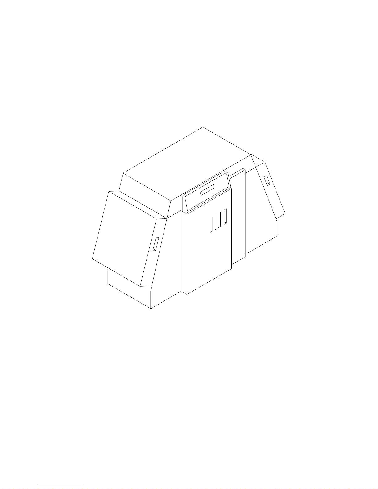
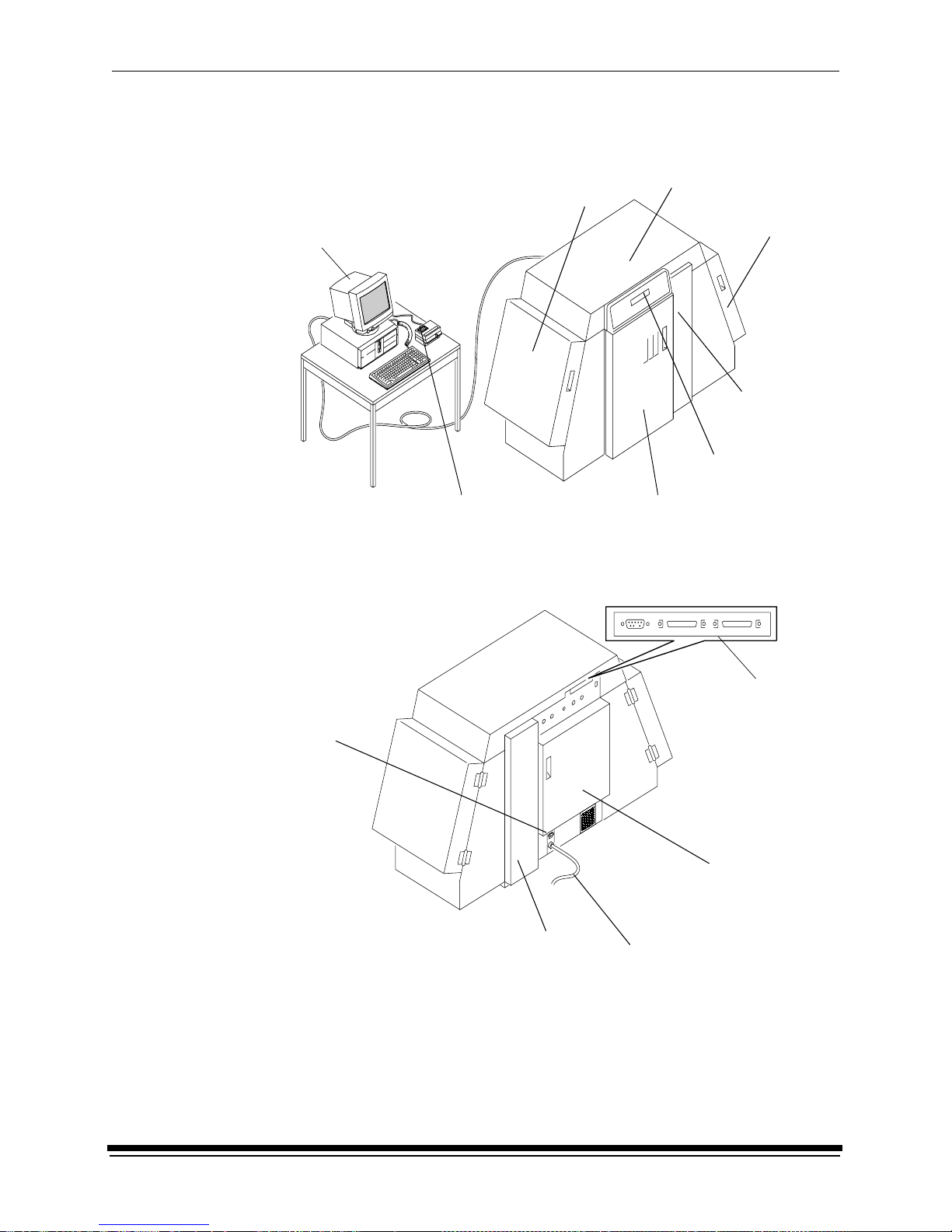
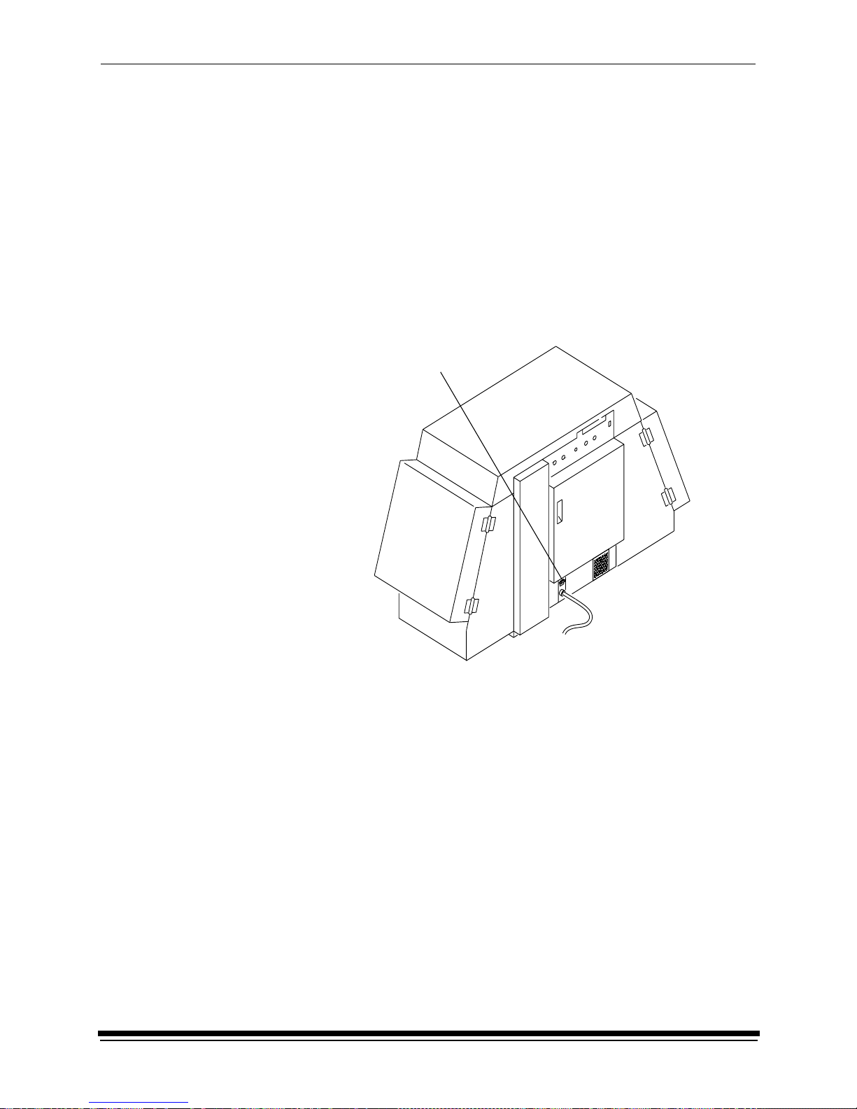
Equipment Overview
host computer and SCSI cable
Front View
densitometer (not included)
front door
paper supply
prin t e r
door
control panel
operator
paper takeup
door
front
slack loop
door
(not included)
Rear View
back door
power cord
ports
connector
circuit
breaker
back slack loop door
Page 19

September 2000 2-1
2 Using the System
This chapter explains how to use the KODAK PROFESSIONAL LED II Printer
20R. It takes you from startup to shutdown. T opics include:
Starting up the Printer ........................................................................................2-1
Calibrat i ng th e Prin ter ........... .......... ................... ......... ................... .......... ..........2-2
Obtaining Densities .....................................................................................2-4
Completing the Calibration ..........................................................................2-6
Making Prints .....................................................................................................2-7
Shuttin g Down the Printer ............................... .......... ................... ................... ...2-8
Soft Shutdo w n.......... ................... .......... ......... ................... ......... .......... ........2-8
Hard Shutdown ...........................................................................................2-9
Starting up the Printer
1. If needed, turn the circuit breaker on the back of the printer on.
2. Press the Start key on the OCP to begin the printer initialization process.
If paper is loaded, when initialization is complete (3 to 4 minutes) the
message “Status: ON LINE - Ready” appears on the OCP . S tartup is complete
and the printer is ready to print. Turn the host computer on; then go to the next
page and calibrate the printer.
If paper is not loaded, the message “Out of paper, open supply door
to load” appears on the OCP. Do the procedures below.
• “Loading Paper Into the Supply Cassette” on page 3-6
• “Installing the Takeup Cassette” on page 3-14
When “On-line and Ready” is displayed, turn the host computer on. Go to
the next page and calibrate the printer.
Page 20
Using the System
2-2 September 2000
Calibrating the Printer
You need to calibrate the printer when you start the system up each day. You also
need to calibrate the printer when:
• you change paper
• print quality is questionable
• the temperature at the site changes more than 5° F (2.8° C)
• if running more than one shift, at the beginning of each shift
If you are calibrating at any time other than during the daily startup procedure:
Before you begin, make sure the printer is not receiving printing commands from
the host.
NOTE: Most windows displayed in this section are from the Windows NT version
of the software. The windows for the Macintosh version of the software are
similar.
For information about editing the calibration settings (for example, you may want
to display a calibration graph only if calibration is out of tolerance), see “Editing
the Calibration Configuration” on page C-20.
To calibrate the printer:
1. Check that:
• the densitometer is connected and calibrated
• the printer status is “Online and Ready”
• the processor is in control
• the calibration application is running
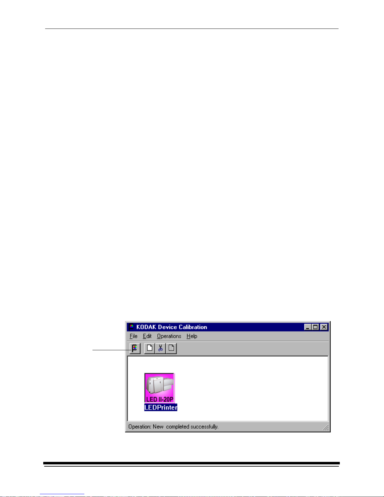
2. Select the icon for the LED Printer on the KODAK Device Calibration screen
and click the Calibrate icon. The calibration software needs complete control
of the printer to successfully calibrate the printer.
IMPORT ANT:If no icon appears on the KODAK Device Calibration screen, you
need to add a calibration device. See “Adding a Device” on
page C-6.
Calibrate
icon
Page 21
Using the System
September 2000 2-3
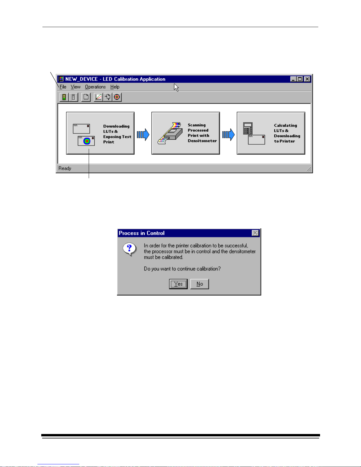
The LED Calibration screen appears.
3. Click Go to start the calibration cycle .
Downloading LUTs and Sending Test Print highlights.
If the configuration file specifies to Ask if processor is in control, the
Process In Control dialog box appears.
The processor is critical to printer calibration. You can calibrate the printer
only if the processor is in control. Densitometers require calibration at regular
intervals. Refer to your densitometer’s manual for instructions on how to
calibrate your densitometer.
4. Click Yes.
Go icon
This icon highlights after
you select Go
Page 22
Using the System
2-4 September 2000
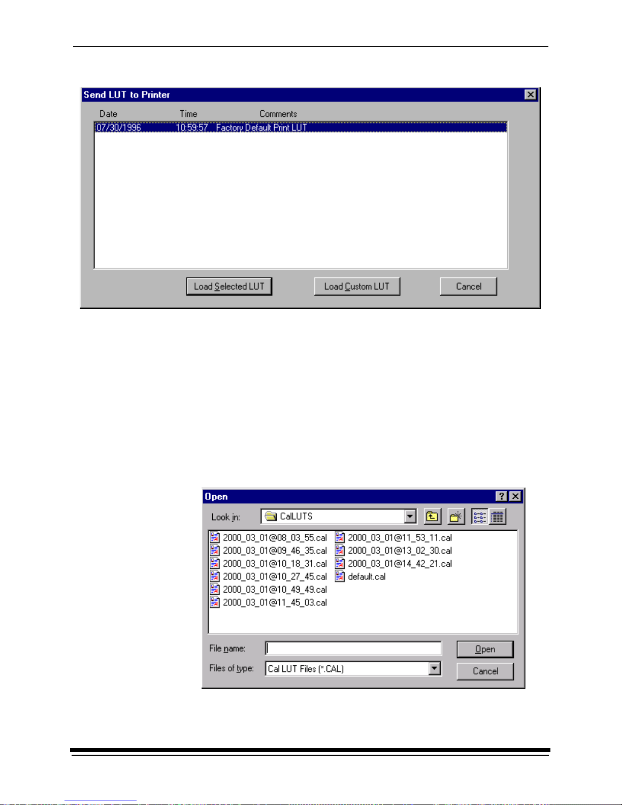
The Send LUT to Printer screen appears.
NOTE: The highlighted LUT in the dialog box above is the most recent
calibration LUT.
5. Click either Load Selected LUT or Load Custom LUT (or Cancel to cancel
the calibration process).
If you click Load Selected LUT, the system automatically downloads the
highlighted LUT to the printer to create a test print.
When the test print has been sent, the Scanning Processed Print with
Densitometer status icon on the LED Printer Calibration screen is
highlighted.
Go to “Obtaining Densities” on page 2-5.
6. If you selected Load Custom LUT in step 5, the Open dialog box appears.
Select or type the name of the LUT file you want and click Open.
Page 23
Using the System
September 2000 2-5
The system automatically downloads the LUT file to the printer to create a test
print. When the test print has been sent to the printer, the Scanning
Processed Print with Densitometer status icon on the KODAK LED Printer
Calibration screen is highlighted.
Obtaining Densities
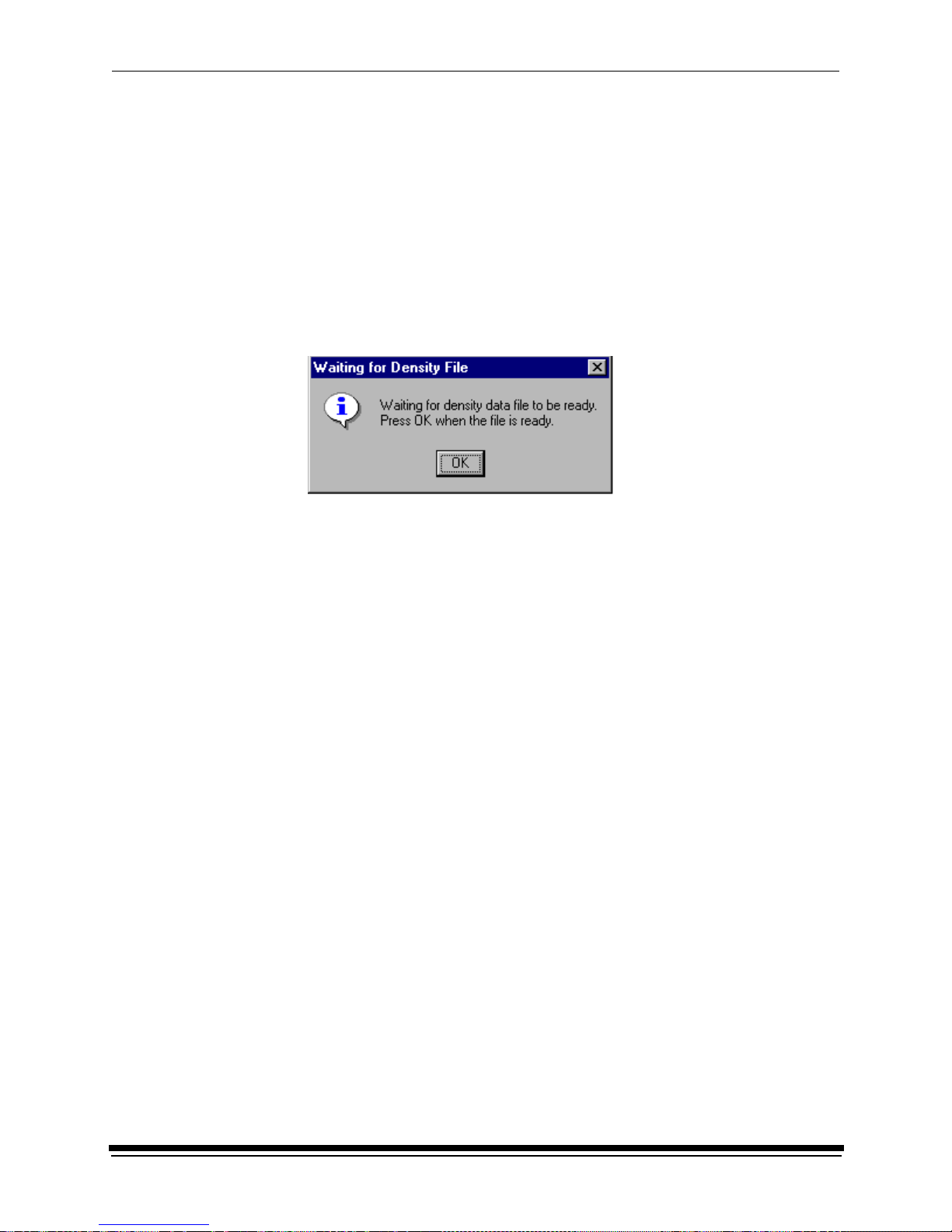
Obtaining Densities from a File
If the configuration settings include obtaining the density data from a file, the
Waiting for Density File dialog box appears. Otherwise, go to “Using the
Densitometer to Read Densities.”
NOTE: T o create a density file, see “Creating a Density File fo r Use with Calibration”
on page C-32.
1. Click OK to continue with the calibration process.
2. Go to “Completing the Calibration” on page 2-6.
Using the Densitometer to Read Densities
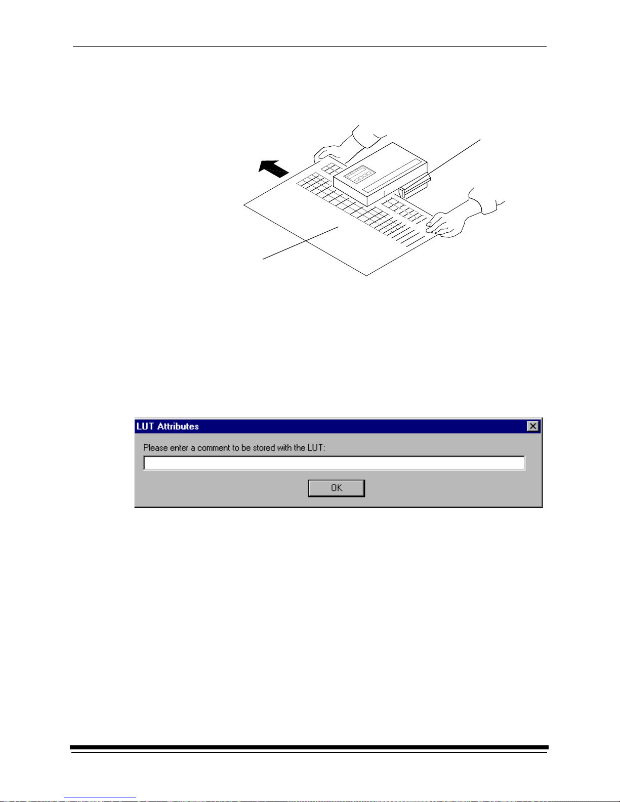
Do the following to scan the neutral (gray) patches on the processed test print into
the densitometer (refer to your densitometer manual for detailed instructions on
using the densitometer):
1. Slide the lever on the densitometer to position 15. Align the edge of the test
print with the lever on the densitometer. Gently feed the test print through the
densitometer to scan the patches labeled “even”.
2. Slide the lever on the densitometer to position 20. Align the edge of the test
print with the lever on the densitometer. Gently feed the test print through the
densitometer to scan the patches labeled “odd”.
Page 24
Using the System
2-6 September 2000
3. Slide the lever on the densitometer to position 30. Align the edge of the test
print with the lever on the densitometer. Gently feed the test print through the
densitometer to scan the patches labeled “both”.
If the test print is read successfully, several messages will appear in the status
bar; the final message indicates that the densitometer values have been
successfull y recei ve d . Go to “Completing the Calibration.”
If the test print is not read successfully, refer to “Calibration Troubleshooting”
on page 5-14.
Completin g th e Calib r ati on
1. If calibration is in tolerance, the LUT Attributes dialog box appears.
a. E n ter a n ame or comment in the dialog b ox . The commen t you en t er w ill
appear on the Send LUT to Printer screen to identify the LUT file with a
name that is meaningful to you (up to 75 characters).
b. Click OK.
The new printing LUT is calculated and downloaded. “Calibration
Complete” appears in the status bar. The calibration is complete.
Test print
Lever
Page 25
Using the System
September 2000 2-7
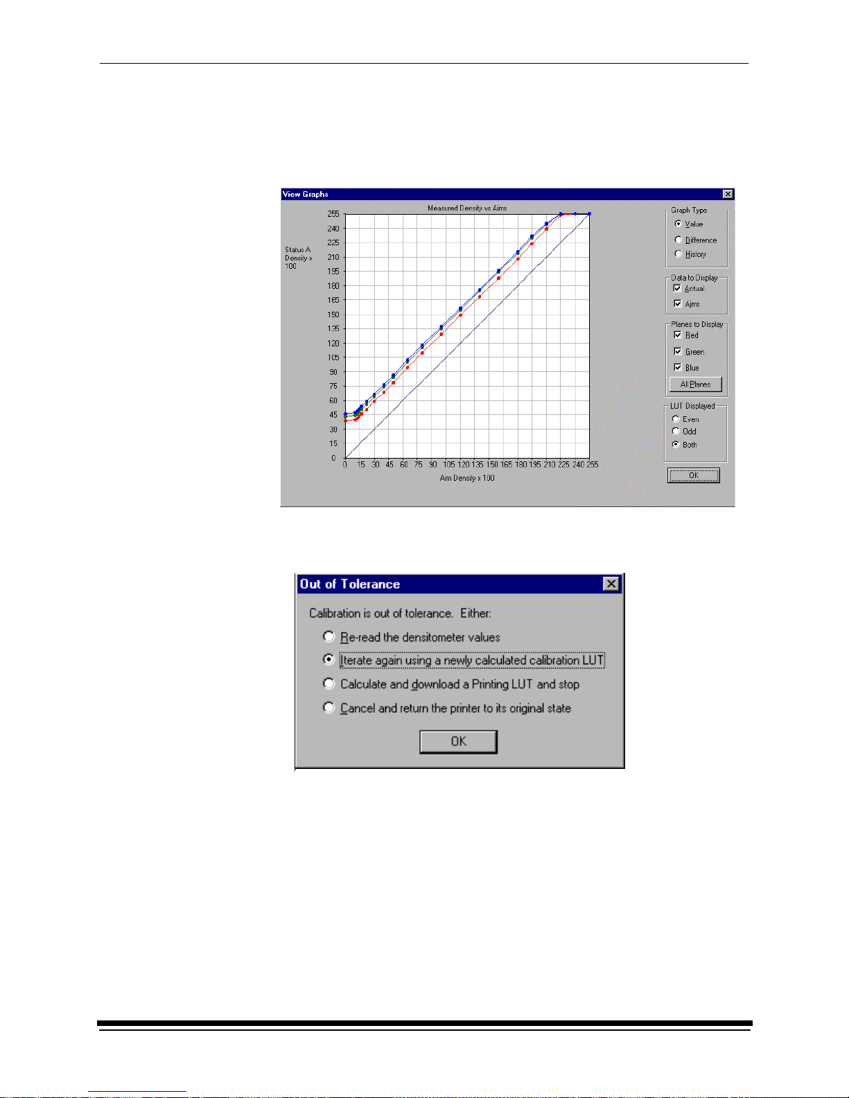
2. If cal ibrati o n is out of toleran ce, it ma y be necessar y to r un four or more
iterations o f the cal ibra tion cycle to achieve a successful cali br at i on.
If the print densities are out of tolerance, a graph appears, allowing you to
select the type of data and planes that you want to see displayed.
a. Click OK.
The following list of options appears.
Re-read the densitometer values is the most useful when the graphs
show an unusual plot. Rereading the test print lets you validate the graph,
then returns you to the Out of Tolerance dialog box.
Iterate again using a newly calculated calibration LUT allows you to
keep printing test prints with the newly created LUT without having to save
the LUT table.
Calculate and download a printing LUT and stop: When you select this
option, the file is saved and given the same creation date and time as the
name.
Cancel and return the printer to its original state saves nothing. Any
corrupted data created after you saved the last time is thrown away.
Page 26

Using the System
2-8 September 2000
b. Select one of the four options to try to complete the calibration
successfully.
• If th e Out of Toleranc e dialog box appears again, repeat this step until
you get a successful calibration; go to step 1.
• If you cannot get a successful calibration, request help from a system
administrator or service person.
Making Prints
You can make prints using the LED Printer 20R with a wide variety of applications
that run on WINDOWS NT Computers and MACINTOSH Computers. One
application that is widely used for printing is the KODAK PROFESSIONAL
Imaging System.
Two applications that you may wish to print from are included with the system.
You can use the KODAK PROFESSIONAL Image Print Server for WINDOWS NT
to print TIFF images. You can use the Export Module for ADOBE PHOTOSHOP
that runs on MACINTOSH Computers to print images from the PHOTOSHOP
application.
For more information about these applications, see the appropriate Appendix in
this guide.
Shutting Down the Printer
There are two methods for shutting down the printer. The soft shutdown method is
the recommended way to shut down the printer overnight or for a period of several
hours. The hard shutdown method should be used for shutting down the printer
for an extended period of time (several days or longer).
Soft Shutdown
IMPORTANT: The soft shutdown method ensures that all printer information is
saved and that the print head is safely turned off if paper is loaded
in the printer.
1. Check that all jobs in the print queue are printed.
2. Press the O n /Off Line k e y on the OCP to tak e th e printe r o ffline.
3. Press the Menu button on the OCP to access the menu.
4. Select “Shutdown” in the message displ ay.
5. Press the Start key.
6. Select “Shutdown now” in the message display.
7. Press the Select key to begin the shutdown.
NOTE: If any jobs are not complete, you will be asked if you want to delete the
remaining jobs before you can select Shutdown.
Page 27
Using the System
September 2000 2-9
Hard Shutdown
Use this method for shutting down the printer for an extended period of time
(several days or longer).
1. Do a soft shutdown. See “Soft Shutdown” on page 2-8.
CAUTION: T urn off the cir cuit breaker only after doing the soft shutdown.
Otherwise, you could lose printer status information and will
cause dark lines to appear in the middle of the prints if paper
is loaded.
2. Turn off the circuit breaker on the back of the printer.
circuit breaker
Page 28

Page 29

September 2000 3-1
3 Operating Procedures
This section provides the information you need to operate the KODAK
PROFESSIONAL LED II Printer 20R. Topics include:
Operator Control Panel (OCP) ...........................................................................3-2
OCP Key/Light Descriptions ........................................................................3-3
Status Messages ............................................................................ ....... ......3-5
Loading Paper Into the Supply Cassette ...........................................................3-6
Removing the Supply Ca sse tte........ ................... ................... ................... ...3-6
Loading the Paper .......................................................................................3-7
Attaching a Digital Paper Saver ................................................................ 3-10
Installing the Loaded Paper Supply Into the Printer ..................................3-12
Installing the Takeup Cassette ........................................................................3-14
Preparing the Takeup Cassette ................................................................3-14
Installing the Takeup Cassette .................................................................. 3-15
Cinching the Media to the Cardboard Core ...............................................3-17
Unloading the Paper from the Printer ..............................................................3-19
Reaching the End of Roll of Paper ..................................................................3-19
Removing the Takeup Cassette ......................................................................3-20
Removing Exposed Paper From the Takeup Cassette .............................3-21
Adjusting the Pape r Hole Punchers ............. ................... ......... ................... ....3-22
Using the Printe r Fea tu re s .......................... ......... ................... ......... ................3-23
Accessing the Me nu ............................... ................... ......... ................... ....3-23
Unloading Paper .......................................................................................3-23
Shutdown and Restart ...............................................................................3-24
Selecting a Loading Option .......................................................................3-24
Changing the Length of Paper Remaining on the Supply Roll ..................3-26
Setting the Length of the Paper Trailer .....................................................3-27
Setting the Punches ..................................................................................3-27
Using the Automatic Roll ID ......................................................................3-29
Using Page Starts .....................................................................................3-29
Resetting the Defaults .......................... ................... ......... ................... ......3-31
Selecting the SCSI Ports ...........................................................................3-32
Setting the Targ e t Pa d Reads ..................... ................... ......... ..................3-32
Selecting A Modem ...................................................................................3-33
Setting the Time and Date ........................................................................ 3-33
Setting the Amount of Space Between Images . ........................................ 3-34
Changing the Units of Measurement for Paper Sizes ...............................3-35
Changing the Gutter Width ........................................................................3-35
Accessing the Software Version Number ..................................................3-35
Setting the Copyright Detection Fea tu r e ......... .......... ................... ......... ....3-36
Handling and Storing the Paper .......................................................................3-37
Storing Paper by Using the Soft Shutdown Feature .................................3-37
About Printing ..................................................................................................3-37
Image Size ................. ......... .......... .................. .......... ................... ......... ....3-37
Buffered and Unbuffered Jobs (or Deferred and Immediate) ....................3-37
Host Software Functions Supported By the Printer ...................................3-38
Page 30
Operating Procedures
3-2 September 2000
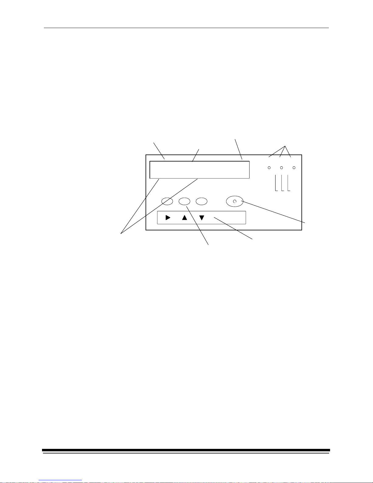
Operator Control Panel (OCP)
The operator control panel (OCP) for the printer allows you to view and control:
• current status of the printer
• current time of day
• paper specifications
• error and power status
• cancel, on/off line and menu functions
• parameters of the printer
• error messages
The display on the OCP is a 4 line by 40 character liquid crystal display (LCD). An
audible beeper is installed to the right of the LCD display. Each of the function
keys also operates as the arrow key (selector) directly below it when Menu has
been pressed. LED indicator lights illuminate to indicate power, error, and standby
statuses.
The operator control panel (OCP) displays the current status of the printer,
includin g the following in f or mation:
• Pages Waiting – the number of printing jobs that are waiting in the print
queue/buffer
• Paper Supply – the approximate amount of paper left in the paper cassette.
This information is input by you and is for your convenience only
• Paper Width – the width of the current roll of paper that is installed in the
printer
• Paper Takeup – the amount of paper that has been fed into the takeup
(“**” will appear in this field if the paper is not cinched in the takeup cassette)
2:43
0
100Paper Width:
Paper Length:Paper Length:
Paper Width:
Status: Initializing
Power Error Standby
Cancel On/Off Line Menu
Start
Select
current status
printing information
time of day
LED indica tor
function keys
Up, Down, and Right
lights
LCD display
select keys
Select
key
Status: Initializing
Pages Waiting: Paper Width:
Paper Supply: Paper Takeup:
Page 31

Operating Procedures
September 2000 3-3
OCP Key/Light Descriptions
Key/Light
Key /LED
Indicat or Li gh t
Description/Function
Start Key The Start key turns on the power for the printer when the printer has
been shut down through the OCP. When using the OCP menu, the
Start key functions as a Select key to select the highlighted item
from the OCP menu.
Cancel Key Pressing Cancel causes the job that is currently printing to quit. In
addition, the printer automatically goes into the Offline mode after
the current printing job has quit.
On/Off Line Key This key toggles between the Online and Offline modes. If you press
this key when the printer is in the Online mode, the printer goes into
the Offline mode. If you press this key when the printer is in the
Offline mode, the printer goes into the Online mode.
Menu Key Pressing this key activates the menu for the OCP when the printer
is in the Offline mode.
Arrow Keys When using the OCP menu, the Cancel k ey functions as a Right
Arrow, the On/Off Line key functions as an Up Arrow , and the
Menu key functions as a Down Arrow.
Select Key When using the OCP menu, the Start key functions as a Select key
to select the highlighted item from the OCP menu.
Power Lig ht The pow er ligh t illu m inates to ind ic ate that the main po w er for the
printer is on.
Error Light The error light illuminates to indicate that a printer error occurred.
Standby Light The standby light illuminates to indicate that the printer has been
shut down from the OCP and is now in the Standby mode, waiting
for Start to be pressed.
Start
Cancel
On/Off Line
Menu
Select
Power
Error
Standby
Page 32

Operating Procedures
3-4 September 2000
Menu
The menu allows you to access other printer features.
NOTE: To access the menu, the print queue must not have any pages waiting to
be printed.
1. Press On/Off Line to take the printer offline.
2. Press Menu.
Taking the Printer Offline
This feature is useful when you need to access the printer OCP menu.
When the printer is offline, it cannot send jobs to the processor or accept jobs
from the host.
To take the printe r o ffl ine, pre ss On/Off Line on the OCP. If a job is printing when
you take the printer offline, the job will complete printing.
Online Mo de
The Online mode is the normal mode and must be activated for the printer to
accept print jobs from the host computer.
Offline Mode
When the printer is in the Offline mode it cannot accept print jobs from the host
computer. When an error occurs, the printer is automatically placed into the
Offline mode.
Cancelling Job s
To cancel the sheet currently being printed, press Cancel on the O CP. After the
sheet has been cancelled, the printer automatically toggles to the Offline mode.
To cancel all jobs wait ing to be printed:
1. Press Cancel on the OCP to cancel the sheet that is currently printing.
2. Press Menu twice.
Printing Deferred or Buffered Jobs
“Pages Deferred” displays on the OCP and a number other than zero displays in
the Pages Waiting field when one or more jobs are waiting to be printed.
1. Press On/Off Line to take the printer offline.
2. Press Menu.
3. Press Start to print the jobs.
Page 33

Operating Procedures
September 2000 3-5
Status Message s
Status messages display on the LCD display of the OCP to indicate the status or
current state of the printer.
Status Message/Printer State Definition
status: ON LINE – Ready The printer is idle and ready to accept jobs.
status: ON LINE – Processing The printer is cu rrent ly downl oad ing or proces sing a
job.
status: ON LINE – Pages Deferr ed Pages are waiting and nothi ng is being
downloaded. If jobs were sent with the “Def er Pr in t”
or “Buffer” option, the printer is waiting for more
data to fill the frame store.
status: ON LINE – Printing The printer is prin ti ng and m ay also be processing
more jobs.
status: OFF LINE – Idle The printer is curr entl y offline. No jobs exist in the
printer. “Idle” is used instead of “Ready” because
the printer is actually idle (not doing anything) and
will not accept jobs.
status: OFF LINE – Processing The printer is off line but a job is being downloaded.
A print cycle will not be initiated.
status: OFF LINE – Pages Deferred The printer is offline but there are jobs in the printer
that are waiting to be print ed. A print cycle will not
be initiated.
status: OFF LINE – Printing The printer will com plete the current print cycle and
then pause.
status: OFF LINE – Cancelling Cancel was pressed when the printer was printing.
The sheet that was printi ng was immediately
terminated. This message is also displayed when
you select “Yes” to the prompt to cancel all
remaining jobs when you enter the menu.
status: In it ializing The print er is powering up (after Standby has been
pressed or the printer has been turned on).
status: ON LINE – Resetting The print engine is bei ng reset because of an error
or operator inter vention. The prin ter will return to the
“ON LINE – Ready” state after the machine reset is
complete (even if the printer was offline because of
an error or key that was pressed before the reset).
status: Print er Er ror :
<Error Message>
A printer error (su ch as a paper jam) has occurred.
The error message is di splayed on the second line
of the display. For a complete list of error
messages, see “Printer Error Messages” on
page 5-1.
Page 34

Operating Procedures
3-6 September 2000
Loading Paper Into the Supply Cassette
WARNING: Mo ve the supply cassette from the printer to a table to load or
unload pap e r.
One 10- to 20-inch supply cassette and one 10- to 20-inch takeup cassette are
included with the printer and are designed to hold rolls of paper that are 10-, 11-,
12-, 20-inch, and A4 widths.
The supply cassette and takeup cassette are not interchangeable.
Removing the Supply Cassette
1. Open the paper supply door.
2. Unlock the cassette clamp for the supply cassette.
3. Remove the empty supply cassette.
clamp
cassette
supply cassette
door
paper supply
Page 35

Operating Procedures
September 2000 3-7
Loading the Paper
1. Unlock the supply cassette locks.
2. Open the supply cassette.
3. If necessary, remove paper scraps from the core support assembly.
4. Remove the old core and support assembly from the supply cassette.
NOTE: Keep the felt surfaces clean to prevent scratches on the paper.
5. Remove the screw lock and the old cardboard core from the core support
assembly.
6. Pull the metal spring for the screw adjuster away from the gear and slide the
screw adjuster to the correct posi tion until it locks into place in the detent .
supply cassette locks
felt
felt
old core and core support assembly
gear
screw lock
screw adjuster
cardboard core
core support
assembly
Page 36

Operating Procedures
3-8 September 2000
TIP: Practice the following steps in the light with an empty cardboard core
before you load a new roll of paper in the dark.
CAUTION: Loading paper into the paper cassette must be completed in
a darkroom with the lights off.
7. Position the paper so that the lead edge of the paper is away from you.
8. Insert the core support assembly from the left side into the roll of paper as
shown.
9. Push the cardboard core toward the gear until it engages the detent.
10. Install the screw lock onto the core support assembly and ensure that it is
snug.
11. Place the core support assem bly with the full paper roll into the supply
cassette.
IMPORT ANT :Make sure that the right and left edges of the paper on the paper
roll remain aligned. Do not allow the roll of paper to slide or
“telescope”.
detent
cardboard core
screw lock
Page 37

Operating Procedures
September 2000 3-9
12. Feed the lead edge of the paper through the slotted opening in the paper
cassette.
13. Close the supply cassette and latch the supply cassette locks.
NOTE: Be sure that the core support assembly rotates freely in the supply
cassette and that the paper feeds freely.
NOTES: – When the paper cassette is locked, you can turn on the room lights.
– See page 3-10 for instructions on how to install a digital printer
paper saver.
IMPORT ANT:When moving the supply cassette, pick up and carry the cassette
by both handles to prevent the paper from sliding or “telescoping”
to one side.
slotted op eni ng
lead edge of the paper
core support assembly
image or emulsion
(side without the gear)
side
supply cassette lock
Page 38

Operating Procedures
3-10 September 2000
Attaching a Digita l Paper Saver
To save paper that is lost during the paper loading process when using the
“1-Step Normal” paper loading option, you may install a digital printer paper saver
(leader) to the lead edge of the roll of paper. Using the digital printer paper saver
reduces the amount of paper lost from threading the printer by 5.5 feet as shown
in the table below.
*For additional paper saving, see “Selecting a Loading Option” on page 3-24.
To order digital printer paper savers and splice tape, see “Leaders and Splice
Tape” on page A-3.
NOTE: The digital printer paper saver may be used many times.
CAUTION: To prevent spots or scratches on images, keep the digital printer
paper saver away from surfaces that have dust and dirt on them.
1. Load the paper into the supply cassette. See “Loading Paper Into the Supply
Cassette” on page 3-6.
2. If necessary, cut a straight edge on the lead edge of the paper that is coming
through the slotted opening in the supply cassette.
3. Cut a piece of splice tape that is approximately 2 inches longer than the width
of the supply cassette.
4. Set the splice tape on the supply cassette with the adhesive side facing up.
5. Place the lead edge of the paper onto the splice tape.
6. Place the trail edge of the digital printer paper saver (the edge without the
hole) on the splice tape.
NOTE: If the digital printer paper saver is new, wipe it with a damp cloth to
remove dust and static electricity.
IMPORT ANT:The digital printer paper saver must be the same width as the
paper. Also, the curl of the digital printer paper saver and the curl
of the paper must match.
Threading Meth od Amount of Unprintable Paper*
Paper Leader 9 feet
Digital Printer Paper Saver 3.5 feet
lead edge
paper saver
digital printer
lead edge of th e
of the paper
splice tape
Page 39

Operating Procedures
September 2000 3-11
7. Fold the edges of the splice tape over the digital printer paper saver and the
paper.
8. Cut a second piece of splice tape that is slightly smaller than the width of the
paper.
9. Install the second piece of splice tape over the paper and the digital printer
paper saver.
10. Turn the core support assembly to rewind the paper and digital printer paper
saver into the supply cassett e .
NOTE: Do not wind the entire digital printer paper saver into the supply
cassette.
second piece of
splice tape
Page 40

Operating Procedures
3-12 September 2000
Installing the Lo aded Pap er Supply Into the P rinter
1. Open the paper supply door.
2. Empty the punch chad tray. See “Removing the Punch Chad” on page 4-2.
3. Align the slot on the bottom of the supply cassette with the plate on the bottom
of the shelf and slide the supply cassette into place on the shelf.
4. Check that the gear on the supply cassette aligns and meshes with the gear
on the printer.
5. Lock the clamp to secure the paper cassette into place.
6. If you are not using the digital printer paper saver, check that the cut on the
lead edge of the paper is straight.
NOTE: Use scissors to cut the paper. Knives and razor blades will shred the
paper.
7. Adjust the right punch to the correct paper width (10, 11, 12 or 20 inch
and A4). See “Adjusting the Paper Hole Punchers” on page 3-22.
8. Press Start on the OCP.
9. Enter the number of feet on the roll of paper when prompted and if necessary,
enter the roll ID. See “Using the Automatic Roll ID” on page 3-29.
plate
shelf
Emulsion
(image) side of
paper (or paper saver)
cassette clamp
slot
Page 41

Operating Procedures
September 2000 3-13
10. When the mess age “Feed paper into printer...” appears, pull the lead edge of
the paper (or digital printer paper saver) out of the paper cassette and place
the lead edge of the paper into the punch slots.
1 1. Slide the lead edge of the paper under the feed roller and static brushes using
both hands. Keep the paper flat until you feel it being pulled into the printer.
Keep the left edge of the paper against the paper alignment guide.
NOTE: The sound from the printer will change when the printer is ready to
advance the paper.
CAUTION: If the paper does not load properly or a paper jam occurs,
press Cancel on the OCP. Remove any paper from the shoe
area and repeat steps 7 through 10. If you are not using a digital
printer paper saver, make sure the lead edge is cut square and
does not have any bends or dings. If necessary , install a new
digital printer paper saver.
12. Close the paper supply door. If a 1-step load option is selected, the paper
automatically advances to the takeup cassette. When this is complete, a
message on the OCP prompts you to load the paper into the takeup cassette.
If a 2-step load option is selected, the prompt to cinch paper appears after the
appropriate length of images has been printed. See “Installing the Takeup
Cassette” on page 3-14.
NOTE: For additional paper saving methods, see “Selecting a Loading Option”
on page 3-24.
cassette
gear on the
lead edge of
the pa per
cassette
printer
gear on the
clamp
(or paper saver)
right hole puncher
guide
paper alig n ment
Page 42

Operating Procedures
3-14 September 2000
Installing the Takeup Cassette
Preparing the Takeup Cassette
1. Unlatch the takeup cassette locks and open the takeup cassette.
2. Remove the core support assembly.
3. Move the screw adjuster to the correct position for the paper size that you are
loading. Pull the metal spring for the screw adjuster away from the gear and
slide the screw adjuster to the correct position until it locks into place in the
detent.
4. Slide the correct size cardboard core onto the core support assembly. Push
the cardboard core toward the flange until it engages the detent.
5. Install the flanged nut (when using 10-, 11-, 12-inch and A4 paper) or the
screw lock (for 20-inch paper) onto the core support assembly. The core
support assembly uses left hand threads. The threaded parts are color coded
to prevent confusion.
NOTE: Make sure the screw lock or flanged nut is secure.
6. Place three rubber bands over the cardboard core.
IMPORTANT:The rubber bands must have the same thickness and must not
be twisted or wrinkled when installed.
core support
assembly
cardboard core
rubber bands
screw
lock
flang e d nut
gear
screw adjuster
Page 43

Operating Procedures
September 2000 3-15
7. Install the core support assembly into the takeup cassette. See the
instructions on the label on the top of the takeup cassette.
NOTE: Make sure that the core support assembly is installed correctly in the
cutouts of the takeup cassette.
8. Close the takeup cassette and latch the takeup cassette locks.
NOTE: Be sure the core support assembly rotates freely in the takeup cassette.
Installing the Takeup Cassette
1. Open the takeup door.
If the takeup cassette is in the printer and has paper in it, remove it.
See “Removing the Takeup Cassette” on page 3-20 or “Removing Exposed
Paper from the Takeup Cassette” on page 3-21.
2. If necessary, move the adjustable cassette support arm to accommodate the
size of the cas s et te y ou will b e us in g. To move the adjusta b le a r m:
a. Unscrew the clamping knob.
b. Move the arm to the correct position.
c. Reinstall the clamping knob and tighten.
core support assembly
takeup
cassette
locks
cutout
Page 44

Operating Procedures
3-16 September 2000
3. Install the takeup cassette onto the cassette support arms.
IMPORT ANT:Check that the bearings on the cassette are seated in the support
arms.
adjustable cassette
support arm
clamping knob
Page 45

Operating Procedures
September 2000 3-17
Cinching the Media to the Cardboard Core
Do the following to cinch (attach) the media (paper or digital printer paper saver)
to the cardboard core:
Cinching Paper to the
Cardboa rd Core
Cinching the Digital Printer
Paper Saver to the
Cardboa rd Core
(a) Hold the lead edge of the paper against the
cardboard core and close to the flange.
NOTE: Align the right edge of the paper with the
flange, making sure that the paper is not
skewed.
(a) Hold the lead edge of the digital printer paper
saver against the cardboard core and close to
the flange.
NOTE: Align the right edge of the digital printer
paper saver with the flange, making sure
that the paper saver is not skewed.
(b) Make a 3 inch cut in the lead edge of the
paper at a 45
o
angle to form a small flap.
(c) Pull t he rubber band that is in the middle of the
cardboard core through the cut in the paper
and push the flap under the rubber band.
(b) Pull the rubber band that is in the middle of the
cardboard core into the slot on the lead edge
of the digital printer paper saver.
correct (paper edge is not skewed) incorrect (paper edge is skewed)
rubber
band
cut
rubber
slot
band
Page 46

Operating Procedures
3-18 September 2000
(d) Turn the flange on the core support assembly
until you have wrapped enough paper around
the cardboard core to cinch it to the core.
(e) Check that the right edge of the paper is still
aligned with the flange and close to it.
(f) Close and lock both sides of the takeup
cassette.
NOTE: The closed takeup cassette should move
freely when you press down on the front
of it. If necessary, reposition the takeup
cassette to move free ly.
(c) Turn the flange on the core support assembly
until you have wrapped enough digital printer
paper saver around the cardboard core to
cinch it to the core.
(d) Check that the right edge of the paper is still
aligned with the flange and close to it.
(e) Close and lock both sides of the takeup
cassette.
NOTE: The closed takeup cassette should move
freely when you press down the front of it.
If necessary, reposition the takeup
cassette to move free ly.
Cinching Paper to the
Cardboa rd Core
Cinching the Digital Printer
Paper Saver to the
Cardboa rd Core
correct incorrect
correct position
cassette is in
cassette moves
up and down
freely
cassette will
not move up
and down
cassette is not in
correct position and
needs to be reseated
in the support arms
Page 47

Operating Procedures
September 2000 3-19
Unloading the Paper from the Printer
The menu provides two options for unloading paper before the end of the roll is
detected:
• Unload Supply and Takeup—Automa ti ca lly makes a cut between the
exposed paper and the unexposed paper. The printer then winds the exposed
paper and trailer into the takeup cassette and rewinds the unexposed paper
into the supply cassette.
NOTE: Approximately 27 inches of unexposed paper will not be rewound into
the supply cassette.
• Unload Takeup and Rethread—Automat ically makes a cut between the
exposed paper and the unexposed paper. The printer then winds the exposed
paper and trailer into the takeup cassette. Paper is then advanced as
appropriate for the loading option selected. See “Selecting a Loading Option”
on page 3-24.
NOTE: Y ou can determine the amount of trailer . See “Setting the Length of the
Paper Trailer” on page 3-27.
To choose one of the above options, see “Unloading Paper” on page 3-23.
Reaching the End of Roll of Paper
When the end of the roll is detected, the remainder of the paper is wound into the
takeup cassette and the message “Out of Paper .. .” is displayed on the OCP. See
“Removing Exposed Paper from the Takeup Cassette” on page 3-21 and “Loading
Paper Into the Supply Cassette” on page 3-6.
If an error has occurred and/or a door has been opened or closed after the printer
reached the end of the roll, the message “Out of Paper...” may display even
though paper is still partially threaded. To completely wind the paper into the
takeup cassette, either reinitialize the printer or see “Unloading the Paper from the
Printer” above.
Page 48

Operating Procedures
3-20 September 2000
Removing the Takeup Cassette
WARNING: Mo ve the takeup cassette from the printer to a table to load or
unload pap e r.
1. Open the takeup door.
2. Remove the takeup cassette from the printer by lifting it off of the support
arms by the cassette handles.
CAUTION: Move the takeup cassette to a darkroom before removing the
exposed paper. See “Removing Exposed Paper from the
Takeup Cassette” o n page 3-21.
cassette handle (2)
support
arm (2)
takeup cassette
Page 49

Operating Procedures
September 2000 3-21
Removing Exposed Paper from the Takeup Cassette
1. Remove the takeup cassette from the printer. See “Unloading the Paper from
the Printer” on page 3-19.
CAUTION: The following steps must be completed in a darkroom.
2. Unlatch the locks on the takeup cassette.
3. Open the takeup cassette.
4. Tape the edge of the paper to the paper roll to prevent the paper from
unwinding.
5. Remove the roll of paper from the takeup cassette.
NOTE: Keep the roll in the horizontal position to prevent it from “telescoping”.
lock (2)
tape
Page 50

Operating Procedures
3-22 September 2000
6. Remove:
• screw lock or flange
• exposed paper from the core support assembly
NOTE: After removing the screw lock, tap the screw lock end of the core to
loosen the paper roll and make it easier to remove from the core support
assembly.
CAUTION: Keep the exposed pape r in a darkroom or a dark bag until you
process it.
Adjusting the Paper Hole Punchers
1. Lift the arm for the right paper hole puncher.
2. Move the right paper hole puncher to the correct location. The hole puncher
falls into a detent on the sliding bar when it is in the correct location.
NOTE: The punch positions for A4 and 12 inch paper are very close together
and can be easily mistaken for each other. Make sure you set the paper
hole puncher to the correct position for the paper you are using.
flange
screw lock
right hole puncher
Page 51

Operating Procedures
September 2000 3-23
Using the Printer Features
The following features are available from the menu on the OCP.
Accessing the Menu
1. Press On/Off line to take the printer offline.
2. Press Menu.
NOTE: If there are jobs waiting to be printed, the following options are available:
• “Cancel” – exit
• “Start” – prints jobs in the print queue and then accesses the menu
• “Menu” – del etes jobs in the print queue and then accesse s the
menu
Unloading P aper
Follow one of the following procedures to unload paper. For more information
about these procedures, see “Unloading the Paper from the Printer” on page 3-19.
Unloading the Supply and Takeup
1. Select “Unload Paper” from the main menu on the OC P.
2. Select “Unload Supply and T akeup” from the main menu on the OCP.
3. Select “Unload Supply and Takeup NOW?”
The printer enters its unload paper sequence. When the unload paper
sequence is complete, the OCP returns to the main menu.
4. Select “Exit” to return to the OCP display. You will be prompted to load
another roll of paper into the printer.
Unloading the Takeup and Rethread
1. Select “Unload Paper” from the main menu on the OC P.
2. Select “Unload Supply and Rethread” from the main menu on the OCP.
3. Select “Unload Supply and Rethread NOW?”
The printer enters its unload paper sequence and you will be prom pt ed to
recinch the takeup cassette. When the unload paper sequence is complete,
the OCP returns to the main menu.
4. Select “Exit” to return to the OCP display.
Page 52

Operating Procedures
3-24 September 2000
Shut down and Restart
Shutdown
1. Select “Shutdown” from the main menu on the OCP.
2. Select “Shutdown NOW?”
This causes the printer to shut down operations and enter the standby mode.
Restart
1. Select “Restart” from the main menu on the OCP.
2. Select “Restart NOW?”
This causes the printer to immediately shut down operations and reboot.
NOTE: This shutdown is not a soft shutdown and does not save the parameter
settings that have been made since the previous startup. Also, using
this feature may cause a black line on the paper in the shoe.
Selecting a Loading Option
The optional paper loading feature, available on the OCP’s main menu, allows
you to choose a loading option depending on your needs. The option you choose
determines how much paper is used during the load and whether or not the first
images from the shoe have cut or order punches.
NOTE: Do not use this feature if you are using a digital printer paper saver.
The four load options are:
• 1-Step Normal (factory default)—The first image exposure will be made on
the paper that was stored before the paper punch when the takeup cassette
was loaded. All images have the appropriate cut and order punches.
• 1-Step Save—Since the paper in the shoe is still unexposed, it is used for the
first image exposure. However, since the paper i s threaded through the printer
during loading, the images on the first exposure are not individually punched.
• 2-Step Dark—the room is completely dark while the paper is being cinched
onto the takeup cassette. When loading, the paper is only partially advanced
through the printer. You must then expose some images and when prompted,
cinch the paper to the takeup cassette in the dark. The first exposure may or
may not be punched, depending on whether you loaded a new roll of paper or
are rethreading an existing roll. This option provides the least amount of
waste.
• 2-Step Light—the room is light while the paper is being cinched onto the
takeup cassette. When loading, the paper is only partially advanced through
the printer. You must then expose some images and when prompted, cinch
the paper to the takeup cassette in the light. The first exposure may or may
not be punched, depending on whether you loaded a new roll of paper or are
rethreading an existing roll.
Page 53

Operating Procedures
September 2000 3-25
Paper Loading Options
NOTE: For options in which the first exposure is not individually punched, the first
exposure will use 33 inches of paper. To minimize paper waste, the size of
the images for the first exposure should total 33 inches whenever possible.
Selecting the Paper Load Option
1. Select “Setup” from the main menu on the OCP .
2. Select “Printer”.
3. Select “Paper Load”.
4. Use the Up and Do wn Arrows to select the desired paper load option.
5. Press Select to select/set the new value.
6. Select “Exit” to return to the previous menu on the OCP.
2-Step Paper Loading
The 2-step paper loading process is used when you choose the “2-Step Dark” or
“2-Step Light” option for paper loading. This process minimizes paper waste by
printing on the paper before the paper is threaded to the takeup area and you
cinch it onto the takeup cassette.
The 2-step loading process is different than the 1-step loading process that is
used for loading paper under “1-Step Normal” or “1-Step Save” conditions. When
you choose “1-Step Light” or “1-Step Save”, the paper is threaded through the
shoe and cinched onto the takeup cassette before images are printed.
Load Op tion
Lead Edge P aper
Waste
Paper Punches
1-Step Normal
(factory default)
108 inches at all images
1-Step Save 62 inches at all images after the
first exposure
2-Step Dark
(new load)
35 inches at all images
2-Step Dark
(rethread)
18 inches at all images after the
first exposure
2-Step Light
(new load)
47 inches at all images
2-Step Light
(rethread)
47 inches at all images after the
first exposure
Page 54

Operating Procedures
3-26 September 2000
Changing the Paper Loading Option
When using the Paper Loading Feature, you should select the paper load option
before you load paper into the printer. However, you can change the paper load
option at any time. If you change the loading option:
• before selecting “Unload Takeup and Rethread” from the main menu on the
OCP, the paper will follow the rethreading procedure for the loading option
that you selected.
• after the paper is loaded but before the first exposure is made, the paper
loading process will not be affected. If you are using the “2-Step Dark” option
and the paper is not cinched, you will still be prompted to “go dark” when it is
time to cinch the paper.
When you change the paper loading option from “1-Step Normal” or “1-Step Save”
or “2-Step Dark” or “2-Step Light”, the printer will print the first exposure on the
paper that is already positioned i n the shoe. Similarly , when you change the paper
loading option from “1-Step Subdued”, “2-Step Dark” or “2-Step Light” to “1-Step
Light”, the first exposure will not be made on the paper in the shoe and all images
will be punched appropriately.
Additional Paper Loss
(For 1-Step Save and 2-Step Rethread Paper Loading Only)
Only one exposure is made on the paper that is in the shoe after loading. Some
paper may be wasted if the total size of the images on the first exposure does not
fully use the paper in the shoe (33 inches). If “Automatic Roll ID” is enabled, the
first image on the roll (for the Roll ID) is 6.5 inches long. This leaves 22.5 inches
available for additional images.
If the first image for the second exposure is less than 12.5 inches,12 inches of
paper between the first and second exposure may be wasted.
If the printer is reinitialized before the first exposure, additional paper is advanced
and all images are individually punched.
Changing the Length of Paper Remaining on the
Supply Roll
The value displayed is the length of paper that is left on the supply roll or in the
takeup cassette. This number should be edited when a new or partially used
paper roll is installed in the printer. You will normally receive a prompt to enter this
number when a new roll is being loaded into the printer. The value should only
need to be modified here if there is a need to change the number. The range for
paper is 0 to 999.
1. Select “Setup” from the main menu on the OCP .
2. Select “Paper”.
3. Select “Supply Length”.
4. Select “Takeup Length”.
5. Use the Up and Do wn Arrows to select a new length for the paper.
6. Press Select to select/set the new value.
7. Select “Exit” to return to the previous menu on the OCP.
Page 55

Operating Procedures
September 2000 3-27
Setting the Length of the Paper Trailer
This value determines the amount of unexposed paper to be added to the trail
edge of the paper wound into the takeup cassette when you send an “Unload
Takeup and Rethread” command.
1. Select “Setup” from the main menu on the OCP .
2. Select “Printer”.
3. Select “Trailer”.
4. Use the Up and Down Arrows to select a new trailer length (from 0 to 3000
pixels).
5. Press Select to select/set the new value.
6. Select “Exit” to return to the previous menu on the OCP.
Settin g th e Pu nc he s
The printer has two paper punches, the back paper punch (closest to the back of
the printer) and the front paper punch (closest to the front of the printer). The f ront
paper punch can be adjusted to accommodate the width of the paper.
The printer is capable of three types of paper punches:
Cut Punc h—occurs automatically between each print. This punch can be made
by either the back or front paper punch.
Order Pu nch —controlled by a command that is sent from the host computer. This
punch can be made by either the back or front paper punch.
Page 56

Operating Procedures
3-28 September 2000
Gutter Punch—controlled by a command sent from the host computer. See
“Changing the Gutter Width” on page 3-35. This punch is on the same side as the
cut punch and is 0.25 to 1.0 in. inside of the image (depending on the value of the
gutter width).
NOTE: All three types of paper punches are made at the trail edges of the print.
Determining the Location of the Cut and Order Punches
1. Select “Setup” from the main menu on the OCP .
2. Select “Printer”.
3. Select “Cut Punches” or “Order Punches”.
4. Select “<>Punch Position”.
5. Select “front” or “back”.
6. Select “<> Punch Enabled”.
Cut and Order Punc hes on Same Side of t he P a per
Gutter Punches With Cut and Order Punches on Opposite Sides of the Paper
Cut and Order Punches on Opposite Sides of the Paper
gutter width 0.25 in.
0.25 in.
cut punches
order punch
white
0.25 in.
white
front of the printer
cut punches
order punch
gutter punches
cut punc hes
order punch
order punch
outline of paper
outline of image
Page 57

Operating Procedures
September 2000 3-29
Using the Automatic Roll ID
The printer has the ability to automatically print a roll identification (roll ID) at the
beginning of each roll.
When this feature is enabled, the roll id will be printed every time paper is loaded
into the printer and every time the paper is rethreaded (for example: when
“Unload Takeup and Rethread” is selected).
The roll ID includes the date, time, and roll ID number. The date and time are the
date and time that the roll of paper was loaded. The roll ID is a three digit number.
This number will automatically increment each time a new roll is loaded. During
loading, this number will be displayed on the OCP. The operator can change the
number or accept the incremented number.
If the printer runs out of paper while printing a job, an asterisk (*) will be printed
after the roll ID on the following roll to indicate that the first print(s) on this roll of
paper belong with the print(s) of the last job that was printed on the previous roll of
paper.
1. Select “Setup” from the main menu on the OCP .
2. Select “Printer”.
3. Select “More”.
4. Select “Roll ID”.
5. Select “Printer ID”. The printer ID will be printed with each roll ID and will not
change.
6. Select “Roll ID Enabled” and toggle to:
• “Yes” if you want a roll ID to be printed at the beginning of each roll
or
• “No” to not print a roll ID.
Using Page St arts
The v alue for “Page Starts” indicates the number of pixels between the back wall
of the printer and the edge of the image. For example, when the printer begins to
print, it moves the print head to the back wall of the printer and then advances it
toward the front of the printer by the number of pixels specified in the “page starts”
parameter (value).
The “page starts” value is set so that the edge of the image closest to the back of
the printer will print off of the paper and will then be borderless on the back edge
of the print.
NOTE: If the image size is wider than the paper, the front edge of the image will
also be borderless.
Page 58

Operating Procedures
3-30 September 2000
Setting the Page Starts Value
1. Select “Setup” from the main menu on the OCP .
2. Select “Printer”.
3. Select “Page Starts”.
4. Select the Page Start you want to modify.
5. Use the Up and Down Arrows to select a new Page Start value.
6. Press Select to select the new value.
7. Select “Exit” to return to the previous menu on the OCP.
Producing Borderless Prints
To achieve borderless prints on both the front and back edges of the paper, you
must set the Page Starts value to adjust the location of the image so that both
edges of the image will print off of the paper.
NOTE: The image width must be at least 76 pixels wider than the width of the paper
to ensure a borderless print. For example:
If white borders are present on either the front or back edge of the print:
1. Measure the white border at both the lead (distance A) and the trail edge
(distance B) and determine its average width.
2. Convert the average width of the white border to a pixel value.
Paper Size Image Width in Pixels
10 inch 2576
11 inch 2826
12 inch 3076
20 inch 5076
A4 3000
outline of the paper
outline of the image
back edge
page start
front edge
Page 59

Operating Procedures
September 2000 3-31
3. Adjust the page starts value to the calculated pixel value. If the white border is
on the:
• back edge—reduce the page start value by the pixel value
• front edge—increase the page start value by the pixel value
IMPORTANT: The page start value for each paper width is different.
Resetting the Defaults
Resetting the Parameters
This procedure resets the parameters of the printer to the factory setup (default)
values. To indicate that the values have been reset to the factory setup values, the
word “done” is displayed in parenthesis after “Reset Param e ters To Fa c tory” on
the menu.
NOTE: Diagnostic parameters are not reset by this action.
1. Select “Setup” from the main menu on the OCP .
2. Select “Defaults”.
3. Select “Reset Parameters to Factory”.
4. Select “Exit” to return to the previous menu on the OCP.
Resetting the Printing LUTs
This procedure resets the Printing LUTs stored in nvram to the factory setup
(default) values. To indicate that the values have been reset to the factory setup
values, the word “done” is displayed in parenthesis after “Reset Printing LUTs To
Factory” on the menu .
1. Select “Setup” from the main menu on the OCP .
2. Select “Defaults”.
3. Select “Reset Printing LUTs to Factory”.
4. Select “Exit” to return to the previous menu on the OCP.
cut edge
cut edge
distance A
distance B
Page 60

Operating Procedures
3-32 September 2000
Resetting the Copyright Detection LUTs
This procedure resets the Copyright Detection LUTs stored in nvram to the factory
setup (default) values. To indicate that the values have been reset to the factory
setup values, the word “done” is displayed in parenthesis after “Reset Copyright
LUTs To Factory” on the menu.
1. Select “Setup” from the main menu on the OCP .
2. Select “Defaults”.
3. Select “Reset Copyright LUTs to Factory”.
4. Select “Exit” to return to the previous menu on the OCP.
Selecting th e SCSI Ports
1. Select “Setup” from the main menu on the OCP .
2. Select “Ports”.
3. Select “SCSI”.
4. Select “SCSI Target ID”.
5. Use the Up and Down Arrows to select a new SCSI ID. Valid SCSI IDs are 0,
1, 2, 3, 4, 5, 6, 7.
NOTE: Make sure the number you select for the SCSI ID has not been assigned
to another device.
6. Press Select to select/set the new value.
7. Select “Exit” to return to the previous menu on the OCP.
Setting the Target Pad Reads
1. Select “Setup” from the main menu on the OCP .
2. Select “Ports”.
3. Select “SCSI”.
4. Select “Target Pad Reads”.
5. Use the Up and Down Arrows to select “Yes” or “No” to indicate whether or
not the SCSI device driver will pad initiator read requests with zeros to the
requested length or simply terminate the SCSI read transaction when it has
sent only the data it has to send.
6. Press Select to select/set the new value.
7. Select “Exit” to return to the previous menu on the OCP.
Page 61

Operating Procedures
September 2000 3-33
Selecting A Modem
Resetting the Modem Port
1. Select “Setup” from the main menu on the OCP .
2. Select “Ports”.
3. Select “Modem (Diag)”.
4. Select “Reset Port”.
5. Select “Reset Modem P ort Now”.
NOTE: This causes the modem port to be set to its original factory setting.
6. Select “Exit” to return to the previous menu on the OCP.
Checking the Modem Presence
NOTE: This causes the printer to query the modem port for the presence of a
modem.
1. Select “Setup” from the main menu on the OCP .
2. Select “Ports”.
3. Select “Modem (Diag)”.
4. Select “Check Presence”.
5. Select “Check Mod em Pres ence Now ”.
6. Select “Exit” to return to the previous menu on the OCP.
Setting the Time and Date
Settin g the Current Time
1. Select “Setup” from the main menu on the OCP .
2. Select “Time”.
3. Select “Current Time”.
4. Use the Up and Down Arrows to select a new time.
5. Press Select to select/set the new value.
6. Select “Exit” to return to the previous menu on the OCP.
Setting the Current Date
1. Select “Setup” from the main menu on the OCP .
2. Select “Time”.
3. Select “Current Date”.
4. Use the Up and Down Arrows to select a new date.
5. Press Select to select/set the new value.
6. Select “Exit” to return to the previous menu on the OCP.
Page 62

Operating Procedures
3-34 September 2000
Setting the Current Day
1. Select “Setup” from the main menu on the OCP .
2. Select “Time”.
3. Select “Day”.
4. Use the Up and Down Arrows to select a new day.
5. Press Select to select/set the new value.
6. Select “Exit” to return to the previous menu on the OCP.
Setting the Amount of Space Between Images
The Page Spacing feature allows you to determine the amount of white space the
printer adds between the images. Having this space between the images
maximizes the image area of each print by centering the cut and order punches
(that will be r emoved late r by a cut t er ) in t h is spac e.
1. Select “Setup” from the main menu on the OCP .
2. Select “Printer”.
3. Select “Page S pacing”.
4. Select “Page S pacing Enabled”.
5. Use the Up and Do wn Arrows to select either “On”, “Off” or “Host Select”.
6. Press Select to select/set the new value.
7. Select “Page Spacing (pixels)”.
8. Use the Up and Do wn Arrows to select the valu e for number o f pixels tha t
you would like for the width of the space between the images.
NOTE: This value must be a multiple of 8 between 8 and 248.
9. Press Select to select/set the new value.
10. Select “Exit” to return to the previous menu on the OCP.
NOTE: Another way to maximize the image area of each print is to overfill
(enlarge) the images through the host software before sending them
to the printer.
Host Select On Off
The amount of space
between the images is
determined by the
input from the host.
If the host does not
specify a value for
page spacing, space is
not inserted between
the images.
The Page Spacing
feature is on and the
amount of space
between the images is
determined by the
value specified in the
“Page Spacing (pixels)”
field.
If the host specifies a
value, this value is
used in place of the
value specified in the
“Page Spacing (pixels)”
field.
The Page Spacing
feature is off.
Space is not inserted
between the images.
Page spacing
information from the
host is not used by the
printer.
Page 63

Operating Procedures
September 2000 3-35
Chang ing the Units o f Measurement for Paper Sizes
1. Select “Setup” from the main menu on the OCP .
2. Select “Printer”.
3. Select “More”.
4. Select “Units”.
5. Select “Units” again.
6. Use the Up and Down Arrows to select either “English” or “Metric”.
7. Press Select to select/set the new value.
8. Select “Exit” to return to the previous menu on the OCP.
Chang ing the Gutter Width
This feature allows you to change the location of the gutter punch that is s ent by a
command from the host computer. The gutter punch is made in the trail edge of
the image. See “Setting the Punches” on page 3-27.
1. Select “Setup” from the main menu on the OCP .
2. Select “Printer”.
3. Select “More”.
4. Select “More”.
5. Select “Gutter: # ”.
6. Use the Up and Down Arrows to select th e valu e f or num ber of pixel s that
you would like the gutter width to be.
NOTE: This value must be between 62 and 250.
7. Press Select to select/set the new value.
8. Select “Exit” to return to the previous menu on the OCP.
Accessing the Software Version Number
1. Select “Setup” from the main menu on the OCP .
2. Select “Printer”.
3. Select “More”.
4. Select “Version” to view the version number for the FEE, PEC and OPC
circuit boards.
5. Select “Exit” to return to the previous menu on the OCP.
Page 64

Operating Procedures
3-36 September 2000
Setting the Copyright Detection Feature
The Copyright Detection feature is designed to protect the copyrighted images of
professional photographers. This feature is applied to copyrighted images to
prevent images from being duplicated.
1. Select “Setup” from the main menu on the OCP .
2. Select “Printer”.
3. Select “Copyright Detection”.
4. Use the Up and Down Arrows to select “Always On”, “Always Off” or “Host
Select”.
5. Press Select to select/set the setting for the new option.
6. Select “Exit” to return to the previous menu on the OCP.
Host Select Always On Always Off
Copyright Detection
can be enabled or
disabled by the host on
a print by print basis
for each image that is
downloaded to the
printer.
Copyright Detection is
enabled and will be
applied to every image
that is downloaded to
the printer.
Copyright Detection is
disabled for every
image that is
downloaded to the
printer.
Page 65

Operating Procedures
September 2000 3-37
Handling and Storing the Paper
Follow the instructions included with the paper for storing and handling the paper
properly.
IMPORTANT: Avoid storing paper in low humidity conditions.
Storing Paper by Using the Soft Shutdown Feature
The Soft Shutdown feature (see “Soft Shutdown” on page 2-8) causes the rollers
to automatically reverse to rewind the lead edge of the paper to the first metering
roller during the soft shutdown process.
About Printing
• A print job is not printed until it is completely downloaded to the printer.
• Print jobs are printed in the order they are received.
• If multiple copies of a print job are requested, they are positioned next to each
other down the length of the roll, regardless of the width of the image.
• It takes the same amount of time to print (expose the paper) a length of 6.5
inches as it does to print 33 inches.
Image Size
The minimum image length is 6.5 inches (1625 pixels). White space will
automatically be added to images smaller than 6.5 inches to increase the image
size to this minimum.
The maximum image length is approximately 33 inches (8248 pixels).
Buffere d an d Unb u ffe re d Jo bs (or Def er red and
Immediate)
Jobs can be stored in memory when downloaded from the host until enough jobs
are downloaded to maximize the printing that occurs during the print cycle.
Most host applications have an option to indicate whether to print the job as soon
as it completes downloading to the printer or to wait until the printer has a full
buffer to print.
If the print job is sent down to the printer with the Unbuffered/Immediate option,
the job will be printed as soon as it completes downloading to the printer.
Regardless of the number of (or size of) the jobs in the printer waiting to print, jobs
sent down with this option will be printed separately.
Page 66

Operating Procedures
3-38 September 2000
In the printer , t he paper is punched before the print job is printed. Since the punch
is upstream of the printing, the first job of the next print cycle may be punched
when positioning the paper for the current print cycle (to reduce waste). If the print
job is sent down to the printer with the Buffered/Deferred option, this indicates to
the printer to wait until it has a full buffer before printing. A full buffer is 26.5 to 33
inches. A print job sent with this option w ill be print ed when:
• the next print job received will not fit within the full buffer length
• the next print job received is requested to be printed unbuffered/immediate
(the job received this way is printed by itself)
• the buffer is forced to be printed (see below)
• the buffer is full and the next print job has started to be downloaded to the
printer
NOTE: If your host application needs to wait until a print job has been completely
downloaded to the printer before it can begin processing the next print job,
this option should not be used with larger widt h p aper . It will slow down t he
productivity of your system.
To print deferr ed or buffered jobs:
“Pages Deferred” displays on the OCP and a number other than zero displays in
the Pages Waiting field when one or more jobs are waiting to be printed.
1. Press On/Off Line to take the printer offline.
2. Press Menu.
3. Press Start to print the jobs.
Host Software Functio n s Supported By the Printer
The printer supports the following functions that may be available through your
host software. Check the documentation for your host software to see if these
functions are available and how to activate them.
Bar Coding
The bar coding function can be used for order tracking, package cutting (for
example type 208), etc.
Pixel Doubling
The pixel doubling function can be used to double the size of an image.
Page 67

September 2000 4-1
4 Maintaining the Equipment
This chapter includes information you will need to maintain the KODAK
PROFESSIONAL LED II Printer 20R. The topics are as follows:
Maintaining the Printer ........................... ......... ................... .......... ................... ...4-1
Daily Maintenance .......................................................................................4-1
Calibrat ing th e Prin ter ..... .......... ......... ................... .......... ................... ...4-1
Removing the Punch Chad ...................................................................4-2
Periodic Maintenance ..................................................................................4-3
Replacing the Air Filter .........................................................................4-3
Maintaining the Printer
Daily Maintenance
Calibrating the Printer
Calibrate the printer after every 8 to 10 hours of operation or when you change
paper emulsions.
NOTE: If the environmental temperature changes more than 5
o
Fahrenheit
(3
o
Celsius) s in c e the printer was las t c alib ra t ed , a cali b ra ti o n w ill be
necessary to maintain the image quality of the prints.
Follow the instructions for calibrating the printer (see “Calibrating the Printer” on
pag e 2-2).
Page 68

Maintaining the Equipment
4-2 September 2000
Removing the Punch Chad
Remove and dispose of the punch chad from the punch chad tray in the paper
supply area every time you add a new roll of paper to the printer.
punch chad tray
Page 69

Maintaining the Equipment
September 2000 4-3
Periodic Maintenance
Replacing the Air Fi lter
The air filter under the shoe should be replaced approximately every 3 months.
1. Open the front door of the printer.
2. Pull back the spring fingers.
3. Remove the air filter.
4. Install a new air filter. For parts ordering information, see “Supplies” on
page A-1.
front door
shoe
air filter
spring finger
Page 70

Page 71

September 2000 5-1
5 Diagnostics and Troubleshooting
This chapter describes the error messages for the KODAK PROFESSIONAL
LED II Printer 20R and offers information for troubleshooting. The information in
this chapter includes:
Printer Error Messages ......................................................................................5-1
Manual or Automatic Reinitialization ...........................................................5-1
Printer Paper Path .......................................................................................5-2
Printer Error Messages ...............................................................................5-3
Miscellaneous Printer Error Messages ................................................. ..... .5-8
Clearing Pap er Jams ....................... ................... ......... ................... .......... ...5-9
Troubleshooting Observable Errors ..........................................................5-11
Additional Troubleshooting Tips for the Printer .........................................5-13
Calibration Troubleshooting .............................................................................5-14
Calibration Graph ...................................................... ....... .. ....... ..... ..... ......5-14
Numbered Error Messages .......................................................................5-14
Non-Numeric Error Messages ...................................................................5-21
Getting Additional Help ....................................................................................5-22
Printer Error Messages
The following messages appear on the printer’s OCP when an equipment
problem occurs:
• Error Messages–indicate an error condition that needs to be corrected
or resolved before you can resume operating the equipment.
(For example: “OUT OF PAPER”, “SUPPLY DOOR OPEN”)
Some error conditions may be easily corrected and some may require the
attention of a high level operator or even a service person.
• Miscellaneous Error Messages–indicates a problem with the printer has
occurred that may or may not require you to call your service person.
More than one problem can occur at a time, however, only the message for the
first error will appear.
Manual or Automatic Reinitialization
The printer will reinitialize when you correct the problem that caused the error
code and press the Start key on the OCP within 30 seconds after closing the
printer door(s).
If you do not press the Start key within 30 seconds after closing the printer
door(s), the error message will disappear and the printer will automatically
reinitialize when you begin to print.
The reinitialization process includes:
• Mechanical Self Check—A self-check of all mechanical systems in the
printer occurs.
• Paper Check—A cut is made across the lead edge of the paper roll to ensure
a clean straight cut. The paper is then repositioned in the shoe.
Page 72

Diagnostics and Troubleshooting
5-2 September 2000
Printer Paper Path
The paper path through the printer is illustrated below. Use this information when
troubleshooting the printer.
WARNING: Do not touch the carriage. Use the translator knob to move the
carriage.
CAUTION: Do not use sharp objects on the shoe.
Rotate the flop preventer knob to move the flop preventer out of the way
before moving the carriage with the translator knob.
takeup cassette
cassette
paper supply
flop preventer knob
metering roller
shoe exit roller
translat o r k no b
knife
shoe
shoe exit nip
EOL
(End of Line)
carriage
(Start of Line)
SOL
motor knob
shoe exit
rotor
tensio n
roller
roller kn ob
metering
takeup
cassette
punch
assembly
Page 73

Diagnostics and Troubleshooting
September 2000 5-3
Printer Er ror Messages
If the error message continues to occur after implementing the possible solutions
from the table below, call your service person.
Error
Code
Error Message Possible Cause Possible Solution
1 not initial ized Attempting to perform a function
before the printer has initialized.
Reinitialize the printer.
2 initiali zing err Attempting to perform a function
during the initialization process.
Wait for initialization to complete and
try the function again.
3 busy Attempting t o perform a function
while the printer is busy perfo rming
another funct ion.
Wait for t he previous function to
complete and try th e function again.
4 out of paper Paper cassette is empty and the
paper pa th sensors do not detect
paper.
Load a full paper cassette into the
printer.
5 end of roll at supply Printer has run out of p aper an d the
tail end of the paper has been
rewound to the paper supply area.
Remove the tail end of the paper at
the supply door and lo ad a ful l supply
cassette into the printer.
6 paper already loaded “Load Paper” was selected when
paper was already loaded.
Solu t i on not required.
7 supply door open,
please close
The paper supp ly door was left
open.
Close the paper supp ly door.
8 front door open, please
close
The front door was left open. Close the front door.
9 back door open, please
close
The back door was left open. Close the back door.
10
takeup door open,
please close
The takeup door was left open. Close the takeup door.
12 motor busy A low level motor move command
was issued while the tim er motor
was in use.
Wait for the mot o r m o ve to co m p le te
or stop the motor and reissue the
command.
13 motor setup invalid A low level motor move command
was issued while the tim er motor
was in use.
Wait for the mot o r m o ve to co m p le te
or stop the motor and reissue the
command.
14 bad printer state The printer can not execute the
requested command.
Reinitialize the printer.
15 timers busy A low level motor move command
was issued while the tim er motor
was in use.
Wait for the mot o r m o ve to co m p le te
or stop the motor and reissue the
command.
16 timer spuri ous interrupt
code
A spurious (false) timer interrupt
has occurred.
No solution required.
17 command not
implemented
The function re quested is not
supported in this software release.
No solution required.
Page 74

Diagnostics and Troubleshooting
5-4 September 2000
18 unexpected OCP reply The 300 boar d sent an unexpected
message to the 200 board.
Call for serv ic e .
20 pec service mode The service swit ch for the 200
board is on, enabling on-board
LEDs that can cause fogging.
Call for serv ic e .
21 opc service mode The service swit ch for the 300
board is on, enabling on-board
LEDs that can cause fogging.
Call for serv ic e .
23 in error state A previous error has not been
cleared.
Reinitialize the printer.
24 middle of load At tempting to perform a function
while paper is being loaded.
Wait until paper loading is complete
and perform the function again.
26 slack loop back door
open
The back slack loop door was left
open.
Close the back slack loop door.
27 slack loop front door
open
The front slack loop door was
left open
.
Close the front sheet slack loop door.
28 unit does not fit The sum of all the unit set up s since
the last print start exceeds 33
inches.
Begin printing.
30 unexpected knife
neither limit
Knife not detected at either end. Call for service.
31
operation fa il ed due to
door open
The door was opened and closed
and paper was fogged.
Reinitialize the printer.
32
need to cinch paper in
takeup
The paper is not cinched correctly
in the takeup cassette.
• Cinch the paper in the takeup
cassette
• Check that the takeup cassette is
installed correctly,
33
end of roll detected The supply paper cassette is
empty.
Remove the paper from the takeup
cassette and inst al l a new r oll of pa per
in the supply cassette.
35
printer needs to cinch
takeup
The paper is not cinched correctly
in the takeup cassette.
• Cinch the paper in the takeup
cassette
• Check that the takeup cassette is
installed correctly.
36
cinch cancell ed, paper
not cinched
Paper loading was can celled after
the prompt to cinch paper.
• Cinch the paper in the takeup
cassette
• Check that the takeup cassette is
installed correctly,
37
error occurred in sheet
transport
An error occurr ed in t he sheet
transport area.
Reinitialize the printer.
64 bad msg checksum A problem with a prom has
occurred.
Call for serv ic e .
Error
Code
Error Message Possible Cause Possible Solution
Page 75

Diagnostics and Troubleshooting
September 2000 5-5
66 paper jam in shoe Jam detect sensor detected
jammed paper at the shoe
entrance.
• Remove jammed paper and un load
the takeup cassette.
• If you are using a digit al printer
paper saver and the paper jammed
before it was cinched in the takeup
cassette, wipe the p aper saver with
a damp, cloth to remove dus t and
static electricity .
• Reload the paper.
67 rotor not up to spee d An obstruction in t he shoe area
prevented the ro tor from achieving
the correct sp eed in the expected
amount of time.
Wait for at least 1 minute, then clear
the obstruction in the shoe and
confirm that all doors are closed.
68 xltr hard limi t detected Either the front or back hard limit
switch was actuat ed.
• Move the translat or off the front or
back hard limit switch. Use the
translator knob.
• Call for serv ic e .
69 unexpected xlator front
limit
The translat or fro nt limit swi tch was
detected unexpectedly.
Confirm that all door s are closed and
reinitialize the printer.
70 xlator front l imit not
detected
The translat or fro nt limit swi tch was
not detected af ter moving translat or
to the front of the pr int er.
Confirm that all door s are closed and
reinitialize the printer.
71 unexpected xlator back
limit
The transl ator back limi t swi tch was
detected unexpectedly.
Confirm that all door s are closed and
reinitialize the printer.
72 xlator back l imit not
detected
The transl ator back limi t swi tch was
not detected af ter moving translat or
to the back of the printer.
Confirm that all door s are closed and
reinitialize the printer.
74 paper present not
detected
Paper was detected at the 11- and
20-inch paper sensors but not at
the 10-inch paper sensors.
Check that the paper is loaded and
threaded proper ly.
75 unexpected 11 inch
paper
Paper was detected at the 11-inc h
paper sensor but not at the 10- or
20-inch paper sensors.
Check that the paper is loaded and
threaded proper ly.
76 1 1 inch paper not
detected
Paper was detected at the
10-inch paper, 20-inch paper, shoe
entrance, and the knif e sensors but
not at the 11-inch pape r sensor.
Check that the paper is loaded and
threaded proper ly.
77
unexpected 20 inch
paper
Paper was detected at the 20- inch
paper sensor but not at the 10- or
1 1-inch paper sensor s.
Check that the paper is loaded and
threaded proper ly.
79 unexpected paper at
shoe entr.
Paper was detected at the shoe
entrance sensor but not at the
paper widt h sensor.
Remove any paper from the shoe.
Error
Code
Error Message Possible Cause Possible Solution
Page 76

Diagnostics and Troubleshooting
5-6 September 2000
80 paper at shoe entr not
detected
During paper loading, the lead
edge of the pape r was not det ect ed
at the shoe entrance sensor within
the expected amount of time.
Load the paper in le ss ti m e.
81 unexpected paper at
knife
• Paper jam occurred as paper
was be ing rev ersed from the
knife to the end of roll and paper
was detected at t he knife instead
of at the shoe entrance.
• Paper sensor at knife or shoe is
not functio ning correctly.
Check that the paper is loaded and
threaded proper ly. Check for a paper
jam at the knife area.
82 paper at knif e not
detected
• Paper was not detect ed at th e
knife when it should have been.
• Paper jam occurred .
• Paper sensor at knife or shoe is
not functio ning correctly.
Check that the paper is loaded and
threaded proper ly. Check for a paper
jam at the knife area.
85 slack loop err, takeup
paper cinched?
The printer was unab le t o takeup
the slack loop bec ause the paper
was not properly cinched.
Check that the paper is pr operly
attached to the cardboard core in the
takeup cassette.
86 slack loop high not
detected
Unable to detect slac k loop. Check that the paper is properly
attached to the cardboard core in the
takeup cassette.
87 timeout waiting to cinch
takeup
The printer door was not closed
within the normal amount of time.
Open the takeup door, atta ch the
paper to the cardboard core in the
takeup cassette and close the takeup
door.
89 unexpected deflector
nip up not detecte d
The deflector nip up swi tch was
detected after moving the deflector
to the down position.
• Check for a paper jam at the sheet
transport area.
• Reinitialize the printer.
90 knife front not det ected The fr ont switch for the knife was
not d etecte d af ter mo ving from front
to back.
Check for a paper jam at the kni fe
area.
91 deflector nip up not
detected
The deflector nip up switch was not
detected after moving the deflector
from the down position to the up
position.
• Check for paper at the sheet
transport area.
• Reinitialize the printer.
• Call for serv ic e .
92 knife back not detected Knifeback swit ch was not detected
after moving kni fe from front to
back.
Check for a paper jam at the kni fe
area.
93 translat or power fault
error
A power faul t w as detected by t h e
translat or puck.
Close all doors and rei nit ialize the
printer.
95 unexpected shoe exit
nip detected
The shoe exit nip made switch was
detected after moving t he shoe exit
nip to the nip unmade position.
Check for a paper jam in the shoe exit
nip area.
Error
Code
Error Message Possible Cause Possible Solution
Page 77

Diagnostics and Troubleshooting
September 2000 5-7
96 shoe exit nip made not
detected
The shoe exit nip made switch was
not detected af ter moving the shoe
exit nip to the nip made posi tion.
Check for a paper jam in the shoe exit
nip area.
97 unexpected deflector
nip made
The deflector nip made switch was
detected after moving the deflector
to the up position.
Check for a paper j am in the deflector
nip area.
98 deflector nip made not
detected
The deflector nip made switch was
not detected af ter moving the
deflector to the up position.
Check for a paper j am in the deflector
nip area.
99 timeout clearing data
patch
The rotor was not able to be
properly st arted.
Call for serv ic e .
100 xlator start failed The translator failed to start. Call for service.
101 shoe exit nip start failed The shoe exit nip fail ed to start. Call for service.
102 deflector start failed The deflector failed to start. Call for service.
109 sheet xport ready
timeout
The sheet transport area remains
busy or initializing process is taking
longer than expected.
Call for serv ic e .
1 10 paper detected in
machine
Paper was detected i n the pr inter
while attemptin g to load a new rol l
of paper.
Remove all paper from the prin ter and
reload the new roll of paper.
1 11 xlator home failed The translator could not find its
home position after several
attempts.
Call for serv ic e .
1 12 invalid paper width
sensor coverage
The paper is not laying flat over the
paper width sensors or the end of
roll has been reached.
Open the supply door and move the
paper to the correct position.
128 back checksum 0 ROM test failed at powerup. Reinitialize the pri nter and call for
service.
129 bad checksum 1 RAM test failed at powerup. Call for service.
130 rotor not stopping Rotor will not turn off. T urn off the pri nter and call for service.
131 xlator at both limits Both the front and back translator
soft limit swi tches are actuated.
Call for serv ic e .
132 knife at both limits Both the front and back knife limit
switches are actuated.
Call for serv ic e .
133 timeout sheet xport
reply
The 300 b oard do es n ot re pl y to the
200 board within the expected
amount of time.
Call for serv ic e .
134 duart self test fai led Duart test failed when the printer
was turned on.
Call for serv ic e .
192 –
219
Various software error
messages.
A software problem has occurred. Shut down and restart the printer.
Call for serv ic e .
Error
Code
Error Message Possible Cause Possible Solution
Page 78

Diagnostics and Troubleshooting
5-8 September 2000
Miscellaneous Printer Error Messages
Miscellaneous error messages indicate that a problem with the printer has
occurred that may or may not require you to call your service person.
Error
Code
Error Message Possi ble Cause Possible S olution
256 door open, please close The paper supply door was left
open.
Close all doors.
257 machine control initialize
error
The printer did not initialize. Reinitialize the printer and call for
service.
258 machine control initialize
timeout
The printer did not initialize in
time.
Reinitialize the printer and call for
service.
259 machine control reply
timeout
A machine control
communications error occurred.
Reinitialize the printer and call for
service.
261 time out waiting t o feed
paper
• Paper did not feed in time
during loading.
• Paper was loaded incor rectly .
• Reload the paper.
• Reinitialize the printer and call for
service.
262 bad communicat ions -
call service
A communications err or has
occurred.
Reinitialize the printer and call for
service.
263 DMA timeout Dat a being sent to the printhead
did not arrive in the spe cified
amount of time.
Reinitialize the printer and call for
service.
264 FIFO empty interrup t Data was sent to the pr inthead to o
quickly.
Reinitialize the printer and call for
service.
265 machine control state
timeout
A message from machine control
did not arrive in tim e.
Reinitialize the printer and call for
service.
266 failure creating test
image
The test image could not be
created.
Follow the instruct ions on the OCP.
267 paper/width mismatch,
end of roll
The end of the paper roll was
detected
.
Load a new roll of paper.
Page 79

Diagnostics and Troubleshooting
September 2000 5-9
Clearing Paper Jams
1. Open the paper supply door.
2. Cut the paper with a scissors or knife.
3. Open the takeup door.
4. If the paper has not already been cut at the takeup cassette area, cut the
paper with a scissors in front of the takeup cassette.
5. Move the right paper punch away from the paper.
cut here
cut here
Page 80

Diagnostics and Troubleshooting
5-10 September 2000
6. Pull the paper out of the printer from the paper supply area.
NOTE: Follow the instructions for clearing paper jams on the paper supply door
label.
CAUTION: Do not use sharp objects when clearing paper jams.
Do not leave small pieces of paper in the printer.
7. If necessary, wind the paper into the takeup cassette.
8. Reload the paper.
9. Close the paper supply door.
CAUTION: To avoid damage to the printer and the digital printer paper
saver, do not send a command that will cut the paper unless
you have removed the digital printer paper saver or you are
certain that it is on the takeup side of the knife.
Page 81

Diagnostics and Troubleshooting
September 2000 5-11
Troubleshooting Observable Erro rs
Observation Pos s ible Cause Possible Solution
A print has a line on it. The circuit breaker was turned off
when paper was in the shoe.
• Do not turn off the circuit breaker when
paper is in the sh oe.
• Do a shutdown pri or to turning off the circuit
breaker.
The printer was disturbed or
bumped during the prin t cycle.
Do not disturb or bump the pri nter during the
print cycle .
The prints have a
repeated unfocused
pattern on the edges.
The roll of paper was dropped on
its edge.
Load a new roll of paper.
The edges are out of
focus.
The relative humidity level is too
low for the paper t o be store d in the
cassette for more than one day.
Increase the humidity level in the room or store
the paper in a sealed plastic bag when it is not
being used.
The prints have a light
leak exposure on the m.
The opening for the control strip
feed box is open.
Store and carry the cassette with the opening
facing down.
The rotor is hi tt in g th e
paper in the printer and
causing noise.
The paper is not loaded correctly. Reload the paper.
The vacuum reduction
insert is damaged and
causing noise i n the
printer.
• The vacuum reduction i nsert
was not installed properly and
has become damaged.
• A damaged vacuum reduction
insert was inst alled.
Properly install an undamaged vacuum
reduction insert.
The paper is being
creased and crumpled
when feeding into the
printer.
The lead edge of the paper has not
been squarely trimm ed and is
being pulled at an angle or
unevenly or it is bei ng loaded at an
angle into the rollers.
1. Pull the paper out of the printer from the
paper supply area.
2. Recut the lead edge of the paper squarely.
3. Reload the paper. Wait for a message and
the push the paper evenly and slowly.
NOTE: If necessar y, remove the curl in the
paper by roll ing the paper on an
empty core in the opposite direction
of the curl.
The paper jams
repeatedly.
Small strips or pie ces of paper are
caught in the printer from the
previous paper jam.
Remove small pieces of paper from the printer.
The splice tape was only installed
on one side of the digital printer
paper saver and the paper.
Apply splice tape to both sides of the paper
and the digital printer paper saver. See
“Attaching a Digital Paper Saver” on
page 3-10.
The prints have not been
cut correctl y by your
cutter.
• The cutter may not be set
correctly.
• The punch marks line up with
the ends of the image.
• Readjust the cut ter.
• Check the positi on of t he paper punch.
Page 82

Diagnostics and Troubleshooting
5-12 September 2000
The boarders on t he print s
are not the right siz e.
The host software’s image
positioning is not correct.
Refer to the instructions for image positioning
in the manual for the host software.
The page start parameter may be
incorrect.
See “Using Page Starts” on page 3-29.
The edge(s) of the prints
are damaged and the
image is skewed.
• The paper is not loaded cor rectly
in the paper casset te.
• The paper supply cassette
clamp is not secured cor rectly .
• The paper supply cassette was
not aligned with the pin when
installed on the shelf.
• The paper supply cassette was
not picked up or carr ied c orrect ly
and the paper has “telescoped”.
• Paper was not straight when it
was fed into the printer.
• The Punch assembly is not
adjusted correc tl y.
• Paper was not fed correctly into
the punch slots.
1. Reload the paper in the paper supply
cassette.
2. Position the paper suppl y cassette on the
pin of the shelf.
3. Close the clamp to lock the paper supply
cassette in to po s it io n .
NOTE: Always carr y the paper cassette with
two hands to prevent the paper from
sliding to one end or “telescoping”.
4. When loading paper into the printer:
• cut the corners of the lead edges of the
paper at a 45
o
angle
• wait for a message to feed
• push the paper slowly into the printer’s
rollers, keeping the paper taut between
the cassette and t he rol lers.
NOTE: Push the paper evenly so that the
paper remains flat and does not
buckle and do not push the paper t oo
hard against the paper alignment
guide.
The edge of the paper i s
damaged in the takeup
area.
• The paper was not straight when
cinched.
• The paper was not centered
when cinched.
• The bearings on the ta keup
cassette were not seated
correctly when the takeup
cassette was placed on the
arms.
Make sure that the takeup cassette is seated
correctly on the arms and can move up and
down a few degrees when you push on the top
of it.
The text on the paper has
flare.
• The text density is too hi gh.
• The processor is not in control.
• The printer is not calibrated
correctly.
• Calibrate the printer.
• Download the latest calibration software
from Kodak’s Web site and then calibrate
the printer.
The host does not
recognize the printer
An error was made during the
power up sequence.
1. Turn off the host computer.
2. Turn off the printer.
3. Power up the printer and wait for it to
initialize.
4. Power up the host computer.
The SCSI IDs are differen t. 1. Change the SCSI ID through the OCP.
2. Turn off the host computer.
3. Turn off the printer.
4. Power up the printer and wait for it to
initialize.
5. Power up the host computer.
Observation Pos s ible Cause Possible Solution
Page 83

Diagnostics and Troubleshooting
September 2000 5-13
Additional Troubleshooting Tips for the Printer
• Be careful to correctly load, seat, and thread the paper into the paper
cassettes.
• Be careful to correctly close all doors prior to printing. Doors ajar or interlock
switches that are not closed will prevent the printer from printing.
• Be sure to follow the proper instructions when installing the digital printer
paper saver.
• Before connecting or disconnecting the SCSI cable or terminator, turn off the
power for the printer and the host computer. Also, if you replace the SCSI
cable, remove the Ferrite bead from the existing SCSI cable and install it on
the new SCSI cable.
The supply or takeup door
will not close.
The latch on the door was pushed
in (flush with the door) when the
door was closed with too much
force.
Pull the latch back to it s normal position with
scissors and cl ose the door with a normal
amount of force.
Observation Pos s ible Cause Possible Solution
latch
Page 84

Diagnostics and Troubleshooting
5-14 September 2000
Calibration Troubleshooting
This section describes the problems that you may occasionally have when using
the KODAK Device Calibration Software or the Calibration Software for the
KODAK PROFESSIONAL LED II Printer. It also identifies the probable causes for
these problems and provides solutions for correcting these problems.
Calibr at io n Gr ap h
The graph below is an indication that the calibration performed was out of
tolerance.
This may be result from invalid densitometer readings. It is necessary to perform
another calibration cycle if you see a graph that looks like the one above.
Numbered Error Messages
Error
Code
Error Code /Status
Message
Possible Cause/Subsystem Possible Solution
1 The fo llo wing file is
locked:_filename_.
The system is trying to access a
file that is currentl y in use.
Close any other applicat ions that
may be accessing the file.
2 The fo llo wing file is
protected:_filename_.
The system is trying to access a
file that is protected.
Change the protections on the file
to grant access to the user.
3 The following file was not
found:_filename_.
The system was trying to access
a file that it could not find.
Verify th at the filename on one of
the configur ation dialog windows is
correct.
4 Error:_oserror_occurred
during operat ion:_operation_
on file:_filename_.
An operating system er ror
occurred.
• Rerun the application.
• Reboot the operating system
5 The fo llo wing file is in an
incorre c t fo rma t:_filename_.
The file does not conform to t he
application specification.
Verify the file format.
Page 85

Diagnostics and Troubleshooting
September 2000 5-15
6 The following file already
exists:_filename_.
The system is trying to save to a
file that already exists.
• Delete the existing file.
• Change the filename.
7 There is not enough sp ace to
create:_filename_.
The system is tryi ng to save a file
but there is not enough disk
space.
Remove any unnecessary files to
increase free disk space.
8 There are too many files to
open _filename_.
Too many files open. Close som e fi les and or
applications.
9 You do not have permission
to open file _filename_.
The file permission i s invalid. Rerun the application.
10 Error copying print LUT to
DP2 folder (can’t open
_filename_.
Folder doesn’t exist or is readonly.
Modify protection on folder.
1 1 Error cr eating DP2 LUT
folder
A folder of the same name may
exist.
Change the selected fo lder name.
101 No response from
device:_devicename_.
The device is not responding to
the system.
Ver ify that the device i s connected
and on-line.
102 Device not
found:_devicename_.
The system was trying to access
a device that it could not fi nd.
Ver ify that the dev ice name on one
of the configurati on dialog
windows is correct.
103 The following device is
indicating it is not
ready:_devicename_.
The device is not ready. Wait several minutes and try the
activity again.
104 The following device is
busy:_devicename_.
The device is busy. Wait several minutes and try the
activity again.
105 The following device is not a
TTY p ort:_devicename_.
The port name in the
configuration file does not ref er to
a valid serial port.
Change the port name in the
configuration file to a valid serial
port.
106 The following device is
closed:_devicename_.
The serial port closed during
system readin g.
• Ver if y that no other application
is accessing the port.
• Restart the application.
107 No data on
device:_devicename_.
No data is available for the
system to read data on th e seri al
port.
• Verify that the densitometer is
connected correctly .
• Restart the application.
108 Error:_oserror_occurred
during operat ion:
_operation_ on device:
_devicename_.
An operating system er ror
occurred.
• Rerun the application.
• Reboot the operating system
• If problem continues, call for
service.
109 Invalid De vice ID:
_devicename_.
Created a new device with an
incorrect device ID.
• Edit th e d e v ice ID to reflect the
correct device ID.
110 Unable to perform operation:
_operation_
Status Message:_statmsg_
Error Message:_errmsg_.
An unknown device error
occurred.
Use the information in the status
message and error mess age to
resolve the device err or.
Error
Code
Error Code /Status
Message
Possible Cause/Subsystem Possible Solution
Page 86

Diagnostics and Troubleshooting
5-16 September 2000
111 There is insufficient memory
for the requested operation
on dev ice:_devicename_.
The application does not have
enough memory to complete the
operation.
Close the other applications and
unnecessary windows.
1 12 A communications time- out
occurred duri ng operation on
device:_devicename_.
The connection between the
printer and host computer was
lost.
Check that all of the cables are
properly connect ed.
113 A device driver for the
following devi ce could no t be
found:_devicename_.
The application could not find the
necessary device sof tware to
communicate with the printer.
Make sure that the Calibration
Application and ASPI SCSI device
driver are installed correctly.
1 14 An error occurred during
comm unications to the
follo w ing dev i c e:
_devicename_.
• The cable between the printer
and the host computer is worn.
• One or more of the
connections between the
printer and the host computer
has malfunctione d.
• Check that all of the cables are
properly connect ed.
• Check the cables and
connections bet ween the pri nter
and the host computer for wear
and if necessary, replace them.
115 An operation error occurred
during communications to
the following device:_
devicename_.
• The cable between the printer
and the host computer is worn.
• One or more of the
connections between the
printer and the host computer
has malfunctione d.
• Check that all of the cables are
properly connect ed.
• Check the cables and
connections bet ween the pri nter
and the host computer for wear
and if necessary, replace them.
116 A software warn ing has been
issued by the foll owing
device: _devicename_ Error
Message: _errmsg_
A software error has occur red on
the printer.
Resolve printer err or condition.
117 A software error has been
detected by the following
device: _devicename_ Error
Message: _errmsg_
An error has occurred on the
printer.
Resolve printer err or condition.
118 A SCSI ID for the following
device was not found:
_devicename_.
SCSI driver not found. Reinstall SCSI driver on host
computer.
119 The wrong SCSI ID was
specified for the following
device: _devicename_.
SCSI ID is incorrect. Set Target SCSI ID to printer SCSI
ID.
120 This devi ce has been setup
for the wrong model of
printer: _devicename_.
Device chosen has not been
found.
Ver if y device chosen matches the
printer model.
121 Unable to read ST A TUS fr om
device: _devicename_.
Unable to see the printer. Check SCSI cable connections.
122 The selected LUT contains
data that exceeds the limits
of this printer.
Trying to send a 12-bit LUT to a
10-bit printer.
Select a 10-bit LUT file.
201 An error occurred while
trying to all oc a te m e mo ry.
The system is trying to allocate
memory, however, no memory is
available.
Close any unnecessary
applications.
Error
Code
Error Code /Status
Message
Possible Cause/Subsystem Possible Solution
Page 87

Diagnostics and Troubleshooting
September 2000 5-17
202 The following parameter is
invalid:_parametername:
_parametervalue_.
An internal er ror occur red wi th t he
software.
• Restart the application.
• If problem continues, call for
service.
203 The funct ion is not suppor ted
by the class.
An internal er ror occur red wi th t he
software.
• Restart the application.
• If problem continues, call for
service.
204 This functi on has not been
implemented.
An internal er ror occur red wi th t he
software.
• Restart the application.
• If problem continues, call for
service.
205 Must enter the following
field:_field_.
The operator left a blank
configuration fi eld.
Enter information in the blank
configuration field.
301 The following key was not
found _key_.
• An internal error occurred with
the software.
• One of the files was edited
manually and a key was
changed.
• Restart the application.
• Restore the key to its previous
value.
• If problem continues, call for
service.
302 The following grouper was
not found:_grouper_.
• An internal error occurred with
the software.
• One of the files was edited
manually and a grouper was
changed.
• Restart the application.
• Restore the grouper to its
previous value.
• If problem continues, call for
service.
303 The call depends on a
current grouper, but the
current gr ouper has not bee n
set.
An internal er ror occur red wi th t he
software.
• Restart the application.
• If problem continues, call for
service.
501 An error occurred while
applying the data.
601 A bad count was entered.
The expected count
was:_count_.
• A file was edited manually and
an incorrect number of rows
was entered.
• An inte rn a l s of tw a re e rro r
occurred.
• Manually enter the correct
number of rows in the file.
• If problem continues, call for
service.
602 An error occurred during the
calculation process.
An internal er ror occur red wi th t he
software.
• Restart the application.
• If problem continues, call for
service.
701 Patch _patch_, column
_column_, value _value_ is
beyond tolerance
_tolerance_ for aim _aim_.
A density patch was out of
tolerance.
Perform another calibration cycle.
702 Patch _patch_ has a spread
of _spread_ which is out of
range _range_.
The spread between color s for a
given density pa tch is out of
tolerance.
Perform another calibration cycle.
703 CalToleranceFile can only be
initiali zed once.
An internal er ror occur red wi th t he
software.
• Restart the application.
• If problem continues, call for
service.
Error
Code
Error Code /Status
Message
Possible Cause/Subsystem Possible Solution
Page 88

Diagnostics and Troubleshooting
5-18 September 2000
704 CalToleranceFile::
initializ e mus t b e called first.
An internal er ror occur red wi th t he
software.
• Restart the application.
• If problem continues, call for
service.
801 Could not find row:_row_. An internal error occur red wi th t he
software.
• Restart the application.
• If problem continues, call for
service.
802 Could not find
column:_column_.
An internal er ror occur red wi th t he
software.
• Restart the application.
• If problem continues, call for
service.
803 Could not find elem ent -
column:_column_.
row:_row_.
An internal er ror occur red wi th t he
software.
• Restart the application.
• If problem continues, call for
service.
804 Row value was not set
before using.
An internal er ror occur red wi th t he
software.
• Restart the application.
• If problem continues, call for
service.
805 Column value was not set
before using.
An internal er ror occur red wi th t he
software.
• Restart the application.
• If problem continues, call for
service.
806 Error deleting row:_row_. An internal er ror occurre d wit h t he
software.
• Restart the application.
• If problem continues, call for
service.
807 Element at row:_row_;
column:_col_
value:_val_ failed audit.
An input file had incor rectly
formatted dat a in i t at the location
indicated.
• Ver if y that you are using the
correct file.
• Edit the file and correct the
format.
910 Configuration file
field:_filename_is invalid.
Calibration wi ll be cancelled.
The user manually edited a fi eld
in a configurati on file and entered
an incorrect value.
• Manually enter the correct
value.
• Reinstall the application.
• If problem continues, call for
service.
911 Error_errcode_occurred.
Processing stopped.
An internal er ror occur red wi th t he
software.
Restart the application.
919 Error occurr ed preparing to
handle exit from Kodak
Calibration. Will not perform
cleanup at exit.
An internal er ror occur red wi th t he
software.
Restart the application.
921 Unable to retur n the pr inter
to its original state. Fix
printer problem and recalibrate.
The application was trying to
cancel but r eceiv ed a n err or when
sending the original LUT back to
the printer.
Printer is in an unknown state.
Correct any printer problems and
restart the appli cation.
922 There is already a printer
open. Please cl ose the open
printer first.
User tried to open a printer when
the printer was already open.
Close the open printer.
Error
Code
Error Code /Status
Message
Possible Cause/Subsystem Possible Solution
Page 89

Diagnostics and Troubleshooting
September 2000 5-19
923 An error occurred during the
loading of a printer. Please
check to make sure the fi le
chosen was of the correct
type and/or format.
An error occurred durin g the
loading of a printer.
Check that the file chosen was of
the correct format or type.
924 No printer loa ded. The operator has not yet opened
a printer.
Open a printer.
941 The height and width values
do not agree with the size of
the target file.
The specified size d oes not matc h
the file size.
Enter the correct file size.
942 Unable to configure
densitometer. Densitometer
configuration file may be
corrupt or lost.
The file CalDevDensGen2.cfg is
corrupt or lost.
Restart the application. If problem
continues, cal l f or service.
1003 Unable to load defaul t
configuration file:_filename_.
The default configuration file was
deleted or renamed or moved.
Restore the file manually or
reinstall th e soft ware.
1004 Unable to set values
in new configuration file.
An internal er ror occur red wi th t he
software.
Restart the application.
1005 Unable to save configurati on
file:_filename_.
The system is tryi ng to save a file
but there is not enough disk
space.
Remove any unnecessary files to
increase free disk space.
1006 Configuratio n file field:_field_
is invalid.
The user manually edited a fi eld
in a configurati on file and entered
an incorrect value.
• Manually enter the correct
value.
• Reinstall the application.
1007 Unable to remove
directory:_directory_.
User does not have update
authority on the dire ctory.
Ver if y that the user has authority
on the directory.
1101 Density DMIN/D MA X poin ts
are invalid.
Density point s are i nvalid. Reread density values on
densitometer or make a new
calibration pri nt.
1102 Density data is not
monotonic increasing.
Density data is invalid. Reread density values on
densitometer or make a new
calibration pri nt.
1103 Exceeded maxim um nu mber
of allowabl e data errors.
Density data is invalid. Reread density values on
densitometer or make a new
calibration pri nt.
1104 Asymmetric Density
Groupings are invalid.
Density data is invalid. Reread density values on
densitometer or make a new
calibration pri nt.
1201 Unknown response fr om
densitometer.
The application received an
unknown response from the
densitometer dur ing
initialization.
Ver if y that the baud rate of the
densitometer matc hes the
applications configuration.
Error
Code
Error Code /Status
Message
Possible Cause/Subsystem Possible Solution
Page 90

Diagnostics and Troubleshooting
5-20 September 2000
1202 Error:_error_from
densitometer.
Unexpected error was returned
from the densitometer.
Calibrate the densitometer . If the
problem continues, check the
manual for the densitometer.
1203 Error: Number of patches
seen by densitometer is
incorrect.
Unable densities on densitometer. Tr y adjusting frame counts or
reread the density patches on the
densitometer.
1300 V alues have not been loaded Matrix file mi ssing. Create a new device.
1301 Data or Matrix files hav e no t
yet been loaded
Matrix file missing. Create a new device.
1302 Data cannot be saved, must
first apply the matrix
Matrix file missing. Create a new device.
Error
Code
Error Code /Status
Message
Possible Cause/Subsystem Possible Solution
Page 91

Diagnostics and Troubleshooting
September 2000 5-21
Non-Numeric Error Messages
Error Message Possible Cause/Subsystem Possible Solution
An underrun error occurred during
communications to the following
device.
• The cable between the printer
and the host computer i s worn.
• One or more of the connections
between the printer and the host
computer has malfunctioned.
• Check that all of the cables are
properly connected.
• Check the cables and
connections between the printer
and the host computer for wear
and if necessary, replace them.
An UNKNOWN error occurred
during communications to the
following device .
An unknown error occur red i n the
application.
• Restart t he calibration application.
• If the problem con ti nues, make
sure you have the Calibration
Application and ASPI SCSI
device driver installed correctly.
Device not found. The host computer attempted to
contact the printer at the specified
SCSI ID but did not get a response.
• Make sure that the printer is
turned on and is on-line.
• Make sure the Calibration
Application and ASPI SCSI
device driver are installed
correctly.
Invalid Device ID. The host computer attempted to
contact the printer at the specified
SCSI ID but did not get a response.
Make sure that the printer is turned
on and is on-line
The following devic e is busy. The printer at the specified SCSI ID
is busy.
Check that all of the cables are
properly connected.
The following device is closed. The connection between the printer
and host computer wa s lost.
Check that all of the cables are
properly connected.
Page 92

Diagnostics and Troubleshooting
5-22 September 2000
Getting Additional Help
Your Kodak Sales Representative is the best source for information about the
KODAK PROFESSION AL LED II Printer 20R.
In addition, technical support is also available in the United States. Call Kodak’s
Technical Assistance Center at 1-800-3Kodak3 from 8:00 a.m. to 11:00 p.m.
Eastern Standard Time on regular business days.
Have your printer’s K-Number ready. The K-Number label is attached to the front
of the printer, next to the operator control panel.
Help numbers for the Asia/Pacific and European regions are listed on the
next page.
Asia/Pacific Region
European Region
Country Country Code Helpline Number
Australia 61 1800-034487
Hong Kong 85 2-5649387
Indonesia 62 21-430-4527
Japan 81 0120-451-881
Korea 82 02-708-5471-4
Malaysia 60 3-757-2722
New Zealand 60 0800500135
Philippines 63 2-816-67-18
Singapore 65 4769-688
Taiwan 88 6-2-893-8234
Thailand 66 2-271-3040-x396
Country Country Code Helpline Number
Belgium 32 02/2632400
Denmark 45 43/717111
Finland 358 90/87071
France 33 1/4989-0083
Germany 49 0711/406-5561
Italy 39 02/66028454
Netherlands 31 03405/99704
Norway 47 02/818181
Spain 34 91/6267100
Sweden 46 08/58023663
UK 44 044261122 Ext.44239
Page 93

September 2000 A-1
Appendix A: Ordering Supplies
This appendix includes ordering information for Kodak accessories, supplies,
paper, leaders and splice tape, and publications.
Accessories
Purchase these items through Kodak.
* Order through you Kodak Sales Representative
Supplies
Purchase these items through your dealer or distributor.
Item Qty/Size
Catalog
Number
X-RITE DTP—36 Densitometer 1 196–1119
US ROBOTICS-SPORTSTER 28.8 Modem 1 873–3743
10 - 20 Inch Paper Cassette 1 159–2971
10/11 Inch Paper Cassette 1 164–0978
10 - 20 Inch Take-up Cas set te 1 861-2079
10/11 Inch Take-up Cassette 1 871-1665
SCSI Interface Kit 1 *
Item Qty/Size
Catalog
Number
Printer Air Filter 1 833-3247
Page 94

Ordering Supplies
A-2 September 2000
Standard (U.S.) Paper
Purchase these items through your Kodak representative.
* NOTE: 12 in. x 574 ft. paper is not supported.
Metric Paper
Purchase these items through your Kodak representative.
*Surface Types
F = smooth, glossy
E = fine grained, lustre
N = smooth, semi-matte
Item
Surface
Types*
Size
KODAK PROFESSION AL Dig ital Paper E, F, or N 10 in. x 262 ft.
KODAK PROFESSION AL Dig ital Paper E, F, or N 10 in. x 574 ft.
KODAK PROFESSIONAL Digital Paper E, F, or N 11 in. x 262 ft.
KODAK PROFESSIONAL Digital Paper E, F, or N 11 in. x 574 ft.
KODAK PROFESSION AL Dig ital Paper E, F, or N 12 in. x 262 ft.*
KODAK PROFESSION AL Dig ital Paper E, F, or N 20 in. x 262 ft.
Item
Surface
Type*
Size
KODAK PROFESSION AL Dig ital Paper E, F, or N 25.4 cm x 80 m
KODAK PROFESSIONAL Digital Paper E, F, or N 25.4 cm x 175 m
KODAK PROFESSIO NAL Dig ital Paper E, F, or N 27.9 cm x 80 m
KODAK PROFESSIONAL Digital Paper E, F, or N 27.9 cm x 175 m
KODAK PROFESSIO NAL Dig ital Paper E, F, or N 29.7 cm x 80 m
(A4)
KODAK PROFESSION AL Dig ital Paper E, F, or N 30.5 cm x 80 m
KODAK PROFESSION AL Dig ital Paper E, F, or N 50.8 cm x 50 m
KODAK PROFESSION AL Dig ital Paper E, F, or N 50.8 cm x 80 m
Page 95

Ordering Supplies
September 2000 A-3
Leaders and Splice Tape
Purchase these items through the appropriate vendor.
* Call 1-800-572-3600 in the United States to order items through Liberty Photo
Products.
Publications
Purchase these items through Kodak Parts Services at 1-800-431-7278.
Item Qty Vendor
Catalog
Number
KODAK 1-Inch Splice Tape 2 Kodak 168-1311
10-Inch Digital Printer Paper Saver 10 Liberty Photo
Products*
L-1210
11-Inch Digital Printer Paper Saver 10 Li berty Photo
Products*
L-1211
20-Inch Digital Printer Paper Saver 10 Liberty Photo
Products*
L-1220
Item Qty/Size
Part Number/
Catalog Number
Operator’s Guide for the:
KODAK PROFESSIONAL LED II Printer 20R
1 Part No. 6B1625
Quick Reference Guide for the:
KODAK PROFESSIONAL LED II Printer 20R
1 Part No. 6B1626
Page 96

Page 97

September 2000 B-1
Appendix B: Specifications
This appendix includes specifications and site requirements information for the
printer.
Printer Specifications
Dimens ions and W eight
To move the printer through a 91 cm (36 in.) doorway, the following parts will be
removed by a Kodak representative:
• front printer door
• rear printer door
• sheet transport module door
• operator control panel
To move the printer through a 71.2 cm (28 in.) doorway, the following parts will be
removed by a Kodak representative (in addition to the above parts):
• enclosures
• covers
• subassemblies for the paper supply module
• knife and sheet transport module
Acoustic Specifications
NOTE: These specifications apply to the Kodak Professional LED II Printer 20R
only.
Width Length Weight
102 cm (40 in.) 149 cm (58.5 in.) 499 kg (1100 lbs)
517kg (1140 lbs)–with paper
Operator
Position
Sound Pressure
Level (L
A
)
Instantaneous
Peak >
130 dB(C)
Sound Power
Level (L
WA
)
Standby 51.3dB(A) NA 66.1dB(A)
Full Syst em
Operating
55.7dB(A) None 71.0dB(A)
Page 98

Specifications
B-2 September 2000
Site Requirements
Operator and Service Access
When fully assembled the equipment requires a minimum of 91 cm
(36 in.) on each side to allow sufficient access for normal operator maintenance
and for service.
Floor Requirements
The equipment should be installed on a smooth, hard, and level floor surface.
Carpet is not recommended.
The floor pitch should not exceed 1 inch in 5 feet.
minimum
minimum
minimum
.91 meters (36 in.)
.91 meters (36 in.)
.91 meters (36 in.)
minimum
.91 meters (36 in.)
1.5 meters (60 in.)
15A
(114 in.)
2.9 meters
3.7 meters (146.5 in.)
Printer
SCSI-2 connection from host here
*
__
2.2 meters + .3 meters (86 in. + 12 in.)
*
3.8 meters (149 in.)
Page 99

Specifications
September 2000 B-3
Electrical
The KODAK PROFESSIONAL LED II Printer 20R is manufactured to operate
within one of the following sets of power constraints or can be configured to do so
by a Kodak representative:
* Phase selection must be completed at the factory or by a trained Kodak
representative.
* *Outside the U.S. and Canada, amperage for the printer is 16A.
Consult with your electrical co ntract or or utility company to ensure that on-s ite
wiring complies with the printer specifications and that wall outlets use isolated
grounds and comply with codes. Further information is provided in the following
sections.
If the equipment is to be permanently connected, then the equipment must be
provided with its own circuit breaker that is located near the equipment within
easy reach of the operator and marked as the disconnecting device for the
equipment.
The unit is an Insulation Category Type II machine, and operates in a Pollution
Degree 2 environment in accordance with IEC 664 (Normal Office Environment).
For technical support, service, repair and fuse replacement information, contact
Eastman Kodak Company’s Technical Assistance Center at 1-800-822-1414.
Power Cords
A 2.4 m (8 ft.), grounded power cord with a special three prong plug is provided
with your printer. The printer conforms to the NEMA N6/15 Printer Plug
Specification.
Special plugs and cords may be required outside of the United States and
Canada. These plugs and cords w ill be prov ided by the Kodak dis tr ibutor (the
power cord provided for international locations must have at least 14 gauge wire).
The power cord should be certified and approved by a national test house.
CAUTION: Make certain nothing obstructs or is placed on power cords. Do
not use extension cords; they can cause voltage loss which may
result in unreliable equipment performan ce or equip men t
damage.
Nominal Voltage/Frequency Voltage Range
Power
Consumption
200 - 240V, 15A, 50/60 Hz,
1 phase*
190 - 254V, 47 - 63 Hz,
1phase, 15 A (Automatic
Sensing)**
Less than
2.4kVA
Page 100

Specifications
B-4 September 2000
Power Outlets
A separate, dedicated power line with a 208 V, 15 amp dedicated receptacle is
required for the printer.
The outlets should meet the following standards:
Line Frequency
In most cases, the electric utility company is responsible for maintaining the
proper frequency of the alternating current in its distribution network. If the
building is supplied with power by its own motor-generator, make certain that the
governor that controls the frequency is capable of delivering power within the
required operating frequency range.
Item Printer Standard
amperage 15 amp
wire size 14 gauge or larger
phase 1 (single)
receptacle NEMA5—N6/15
impedance between ground and
neutral wires
less than 2 ohms
voltage drop across the circuit
breaker
less than 0.1 volts
distance between receptacle and
equipment
1.5 m (5.0 ft.)
or less
 Loading...