

Page 1
{SiteSp ecifications}{Production}{ KodakServiceSup port}
KODAK PROFESSIONAL LED II PRINTERS 20P/20R
SITE SPECIFICATIONS
for the
Publication No. SS2616-1
23NOV99
Supersedes SS2616-1
15JUL97
KODAK PROFESSIONAL LED II PROCESSOR 20P
G130_1000HA
© Eastman Kodak Company, 2000
Page 2

PLEASE NOTE The information containe d herein is based on the experience and knowledge relating to the
subject matter gained by Eastman Kodak Company prior to publication.
No patent license is grante d by this information.
Eastman Kodak Company reserves the right to change this information without notice, and
makes no warranty, express or implie d, with respect to this information. Kodak shall not be
liable for any loss or damage, including consequential or special damages, resulting from any
use of this information, even if loss or damage is caused by Kodak’s negligence or other fault .
Table of Contents
Description Page
Site Specifications . . . . . . . . . . . . . . . . . . . . . . . . . . . . . . . . . . . . . . . . . . . . . . . . . . . . . . . 3
Space Requirements
Operating Environment
Electrical Requirements
Plumbing Requirements
Venting Requirements
Other
. . . . . . . . . . . . . . . . . . . . . . . . . . . . . . . . . . . . . . . . . . . . . . . . . . . . . . . . . . . . . . 7
. . . . . . . . . . . . . . . . . . . . . . . . . . . . . . . . . . . . . . . . . . . . . . . . . . 3
. . . . . . . . . . . . . . . . . . . . . . . . . . . . . . . . . . . . . . . . . . . . . . . . 3
. . . . . . . . . . . . . . . . . . . . . . . . . . . . . . . . . . . . . . . . . . . . . . . 4
. . . . . . . . . . . . . . . . . . . . . . . . . . . . . . . . . . . . . . . . . . . . . . . 7
. . . . . . . . . . . . . . . . . . . . . . . . . . . . . . . . . . . . . . . . . . . . . . . . . 7
2 23NOV99 – SS2616-1
Page 3
Site Specifications
Section 1: Site Specifications
Space Requirements
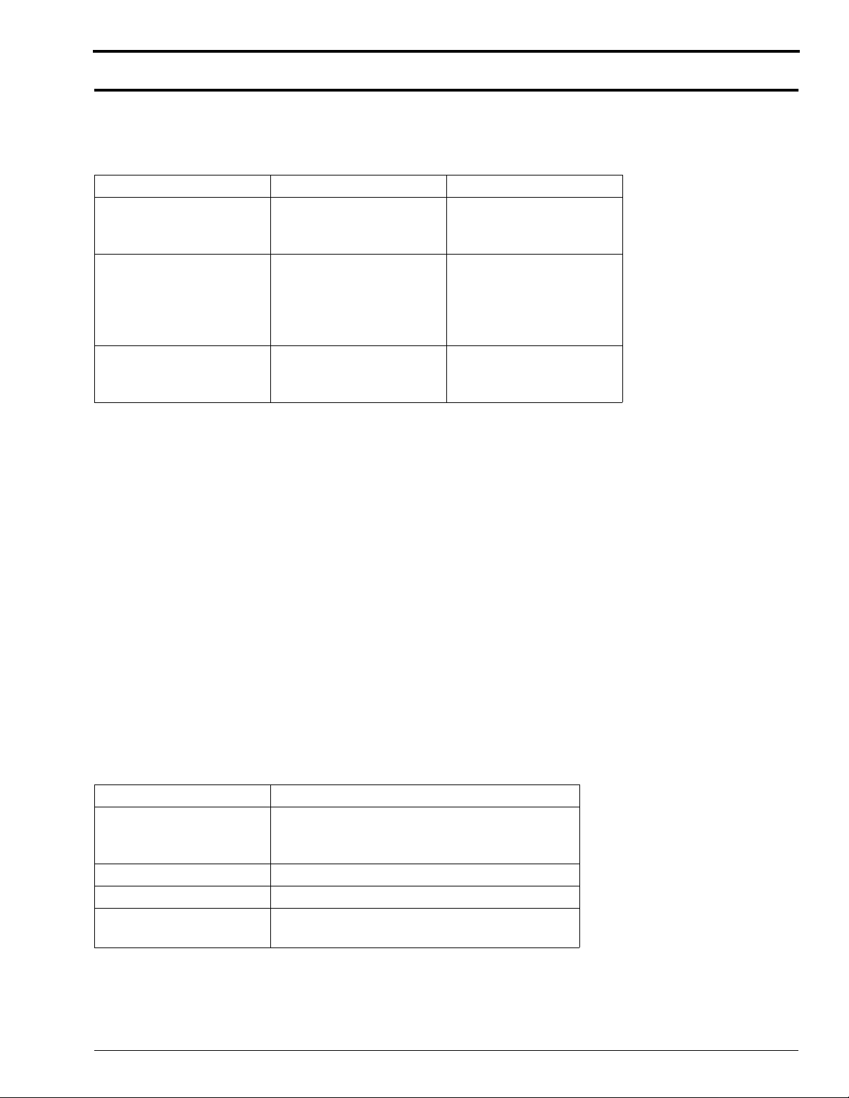
Dimens ions and Weight (Uncrated)
Width Length Weight
Printer:
102 cm (40 in.)
Processor:
87.6 cm (34.5 in.)
Roll-to-roll Printer:
102 cm (40 in.)
Site Access:
Doorways to the site should be 91centimetr es (36 inches) wide, or larger. The front and rear PRINTER FRAME
DOORS, SHEET TRANSPORT MODULE DOORS, and the OPERATOR CONTROL PANEL (OCP) must be
removed to move the PRINTER through a 36 inch doorway.
Minimum acceptable door size is 71.2 centimetres (28 inches). The enclosures, covers, and subassemblies for the
PAPER SUPPLY MODULE, the KNIFE AND SHEET TRANSPORT MODULE, and the TAKE-UP MODULE†
must be removed to move the PRINTER through a 28 inch doorway.
† Roll-to-roll system only.
Operato r and Service Access:
When fully assembled, the sys tem requir es a minim um of 91 cm (36 in .) on each si de to a llow ac cess for se rvic e and
operator maintenance .
Floor:
The system should be installed on a smooth, hard, and level floor surface. Floor pi tch should not exceed 1 inch in 5
feet.
149 cm (58.5 in.) 420 kg (925 lbs)
429 kg (945 lbs) with
paper.
130 cm (51 in.)
without removable print
rack.
198 cm (78 in.) with print
rack installed.
189 cm (74.5 in.) 510 kg (1125 lbs)
172 kg (380 lbs)
312 kg (471 lbs) with
processing chemicals.
519 kg (1145 lbs) with
paper.
Operating Environment
The unit to be installed is an Insul ation Catagor y Type II machi ne and operates in a Pollut ion Degree 2 environment
in accordance with IEC 664 ( Normal Office Environment ).
Description Specification
Temperature* 15.5-26.6°C (60-80° F) for unplum bed
systems15.5-30° C (60-86° F) for plumbed
systems
Relative Humidity 15-76%
Altitude 0-2000 metres (6562 feet)
Lighting maximum of 325 lux **
(30.2 foot-candles)
* Room temperature changes of more than 5 degrees during operation will require recalibra tion of the PRINTER.
**Although the PRINTER an d PROCES SOR operate in normal room lighting, access to a darkroom is required for
loading paper into cassettes.
SS2616-1 – 23NOV99 3
Page 4

SITE SPECIFICATIONS
Electrical Requirements
Power
Voltage Range/
Frequency*** Power Consumption
Roll-to-processor Printer: 200-254V,
47-63Hz, 1phase, 15A
Processor: 208-254V,
47-63Hz, 1phase or 3
phase**, 30A
Roll-to-roll 200-254V, 47-63Hz,
1phase, 15A
** Phase selection must be completed by CES personnel.
*** Outside the U.S. and Canada, amperage for the PRINTER is 16A, and the amperage for the PROCESSOR is
32A.
Note
To prevent processor failur es caused by power fluctuations, purcha se a Square-D Buck and Boost Transformer
(Model #500SV43F) EK Catalog #869-7799. Other transformers may not provide satisf actory results.
Less than 9.12kVA.
Less than 2.4kVA.
Within the US and Canada, the PRINTER is supplied with a 2.4-met re (8-foot) POWER CORD. The power
receptacle m ust be lo cated within 1. 2 me tres 30 cm ( 4 feet 1 foot) of the re ar of the PRINTER. This powe r r ecept acle
should be a dedicated line with a separate CIRCUIT BREAKER. The receptacle must accept a PLUG which
conforms to NEMA N6/15 (printer plug specif ication). Outside the US and Canada, the regi on will supply the
appropriate locally approved POWER CORD and PLUG. The POWER CORD s hould be cretified and approved by
a national test house.
Within the US and Canada, the PROCESSOR is supplied with a 2.4-metre (8-foot) POWER CORD which enters the
cabinet from below. The power receptacle must be located within 2.4 metres 30 cm (4 feet 1 foot) of the rear of the
PROCESSOR. This power receptacle should be a dedicated line with a separate CIRCUIT BREAKER. The
receptacle must accep t a PLUG which conforms to NEMA L6-30P (processor plug specification). Outside the US
and Canada, the region will supply the appropriate locally approve d POWER CORD and PLUG.
A PROTECTIVE EARTH GROUND must be supplied when installing the PROCESSOR.
4 23NOV99 – SS2616-1
Page 5

Space requirements for a roll-to-processor system
Site Specifications
3.5 meters + .3 meters (138 in. + 12 in.)
2.2 meters + .3 meters (86 in. + 12 in.)
1.5 meters (60 in.)
.91 meters (36 in.)
minimum
__
.91 meters (36 in.)
.91 meters (36 in.)
_
minimum
*
Printer
minimum
15A
_
30A
2.9 meters
(114 in.)
Processor
.91 meters (36 in.)
minimum
SCSI−2 connection from host here
*
External modem connection here
G130_0600DA
4.5 meters (179 in.)
SS2616-1 – 23NOV99 5
Page 6

SITE SPECIFICATIONS
Space requi re m ent s for a roll-to - ro ll sys te m
2.2 meters + .3 meters (86 in. + 12 in.)
__
1.5 meters (60 in.)
15A
.91 meters (36 in.)
minimum
2.9 meters
(114 in.)
*
G130_0601DA
.91 meters (36 in.)
minimum
.91 meters (36 in.)
3.8 meters (149 in.)
SCSI−2 connection from host here
*
External modem connection here
Printer
minimum
.91 meters (36 in.)
minimum
SCSI Co nnection to Ho st Computer:
The proper configurat ion of the SCSI-2 connection will depend on the distance of the host computer from the
PRINTER.
A single-ended connection can be used if the total dista nce is less than 6 metres (19.7 feet). The customer must supply
a SCSI-2 data CABLE (FAST 20 type) and a SCSI-2 TERMINATOR for single-ended connection. An active FPT
type (forced perfect termination) SCSI-2 TERMINATOR is recommended.
A differential connection must be used if the distanc e is between 6 a nd 22.9 metres ( 19.7 and 75 fe et). The customer
must supply a SCSI- 2 data CABLE and a SCSI-2 TERMINATOR for differential connection. A differential SCSI2 TERMINATOR is required.
Switching from a single-ende d to a differential SCSI-2 connecti on requires a reconfiguration of the FEE BOARD.
Refer to the INSTALL INSTRUCTIONS for detailed information on how to do this.
Locate SCSI-2 CABLES away from any source of electrical interference (e.g. transformers, fluorescent light ballast).
6 23NOV99 – SS2616-1
Page 7

Site Specifications
Plumbing Requirements
Water Supply:
Adequate water supply and drainag e is the cust omer’s responsibility, and must be installed to specifications by the
customer before installation of the PROCESSOR begins.
A WATER SUPPLY PANEL for plum bed systems is available from Kreonite (WPS-A), and is recommended.
Kodak will install fle xible supply line to PROCESSOR and an elect rical connection to th e SOLENOID. The WATER
SUPPLY PANEL should be wall-mounted within 4.9 metres (16 feet) of the rear of the PROCESSOR.
Technical support and warran ty of WATER SUPPLY PANEL is the responsibility of Kreonite.
Water to a plumbed system must meet the following speci fications:
Flow rate: 3.8-20 liters per minute (1-5 gallons per minute)
Temperature: Hot- 59 C (120 F) minimum temperature . Col d-27 C (80 F) maximum temperature. Practically, the
water temperature shoul d be adjusted to ≥35C (95 F) to minimize the time necessary to bring the PROCESSOR to
operating temperature .
Waste Wate r:
A floor drain should be located convenient to the PROCESSOR.
The drain system should conform to local specifications for silver-laden bleach-fix, and stabilizer or waste water.
Kodak will insta ll a flexible drain TUB E to the PROCESSOR. The customer will be responsible for connection of
the flexible drain TUBE to a locally appr oved drain system.
In unplumbed systems, the PROCESSOR is supp lied with 10-lit re CONTAINERS for eas y transpo rt of waste to the
site waste faciliti es. Waste CONTAINERS will be located under the PROCESSOR.
A sink, 61 cm (24 in.)wide or larger, located near the PROCESSOR, is recom mended for use during cleanup.
Venting Requirements
For a roll-to-processor system, 10 complete changes of air in the room per hour are required.
For a roll-to-roll printer, no venting is required.
Other
Telephone: The customer must s upply a telephone line (with RJ11C modular phone jac k) within 3 metres (10 f eet)
of the PRINTER to allow remote diagnostic suppor t via modem. A high-grade analog service line is recommende d.
Densitometer: An X-Rite DTP-36 densit ometer is strongly recommended for calibr ation of the PRINTER and for
process control.
SS2616-1 – 23NOV99 7
Page 8

Printed in U.S.A . • ss2616_1_23nov99.fm
EASTMAN KODAK COMPANY
Rochester, NY 14650
Kodak is a trademark.
 Loading...