

Page 1

Publication No. XP3210-006
Repairing the
LASER PRINTER KEYPAD
a component of the
3230 Kodak Ektascan 2180 LASER PRINTER,
3226 Kodak Ektascan 1120 LASER PRINTER,
3210 Kodak Ektascan LASER PRINTER
Model 100 XLP,
3222 Kodak Ektascan LASER PRINTER
Model 100 XLP Upgrade,
18JUL97
3140 Kodak Ektascan IMAGE MANAGER
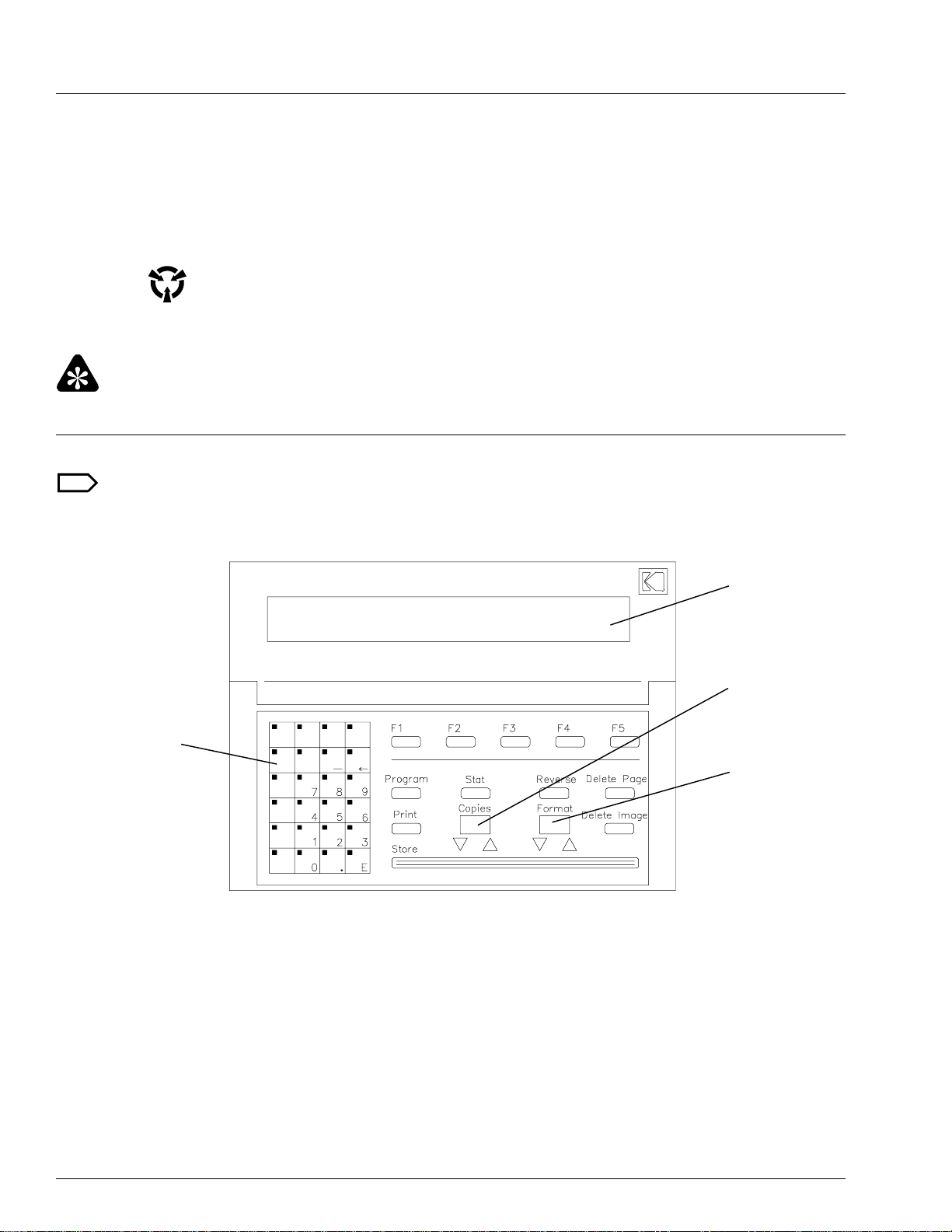
Purpose: Use this procedure to repair only the KEYPAD with the tilting MESSAGE DISPLAY, identified by
the figure below.
Order a replacement KEYPAD only if the KEYPAD cannot be repaired.
HEALTH IMAGING
© Eastman Kodak Company
H027_2527AA
Page 2

MISCELLANEOUS PUBLICATION
Repair Time: Approximately 30 minutes maximum
Special Tools: PUMP, VACUUM DESOLDER TL-3314 or WICK, SOLDER 1C8129
Parts Status: Available from Service Parts Management
Parts Requirements: KEYPAD Repair Kit, Part Number 9B1510
Note: Order the Repair Kit once and order replacement parts. Feedback
information about the parts to SCAN.
KEYPAD Repair kit, Part Number 9B1510
(Parts are available separately)
Item Part Number Description Qty.
1 981821 DC-DC CONVERTER (incl. adhesive pad) 2
2 911355 MESSAGE DISPLAY BOARD 1
3 2B6808 KEYPAD OVERLAY/BOARD ASSEMBLY 1
4 9B1506 STANDOFF, hex, male/female 6
5 9B1507 BUSHING, hex, threaded, female/female 6
6 914278 SHORT STANDOFF 6
7 914279 LONG STANDOFF 6
8 914276 SPACER, plastic 6
9 914287 SHORT SCREW, plastic 6
10 914288 LONG SCREW, plastic 6
11 575822 WASHER, metal 6
12 1C8148 LOCKTITE 414 ADHESIVE, 1 oz. bottle 1
13 6C5726 CASE and PART BOX 1
2 18JUL97 – XP3210-006
Page 3
PLEASE NOTE The information contained herein is based on the experience and knowledge relating to the
subject matter gained by Eastman Kodak Company prior to publication.
No patent license is granted by this information.
Eastman Kodak Company reserves the right to change this information without notice, and
makes no warranty, express or implied, with respect to this information. Kodak shall not be
liable for any loss or damage, including consequential or special damages, resulting from any
use of this information, even if loss or damage is caused by Kodak’s negligence or other fault.
This equipment includes parts and assemblies sensitive to damage from electrostatic
discharge. Use caution to prevent damage during all service procedures.
Important
Use qualified personnel to make the repair.
Diagnosing the KEYPAD Malfunction
Note
The PRINTER and INTERFACE must be ON and in the READY mode before you diagnose the KEYPAD.
You cannot diagnose the KEYPAD correctly if the PRINTER and INTERFACE are in the START-UP or SELFTEST modes.
MESSAGE
DISPLAY
’COPIES’
DISPLAY
NUMERIC
KEYPAD
’FORMAT’
DISPLAY
H027_2508BCB
H027_2508BA
[1] Check that the KEYPAD CABLE is connected correctly.
[2] Press the Format ▲ key several times. As you press the key, observe the illumination of the NUMERIC
KEYPAD and listen for a beep each time the key is pressed.
[3] Study the following and check for incorrect or erratic displays:
• MESSAGE DISPLAY
• NUMERIC KEYPAD
• ‘COPIES’ DISPLAY
• ‘FORMAT’ DISPLAY
3 18JUl97 – XP3210-006
Page 4

MISCELLANEOUS PUBLICATION
6 SCREWS
BACK COVER
H027_2522ACA
H027_2522AC
SCREWS
ESD
Possible damage from electrostatic discharge.
[4] If the KEYPAD does not operate correctly,
remove the six screws and BACK COVER from
the MESSAGE DISPLAY.
[5] Check that the CONNECTOR on the RIBBON
CABLE engages the MESSAGE DISPLAY
BOARD.
ESD
Possible damage from electrostatic discharge.
H027_2516ACA
H027_2516AC
MESSAGE
DISPLAY
RIBBON
CABLE
FOOTSWITCH
BOARD
KEYPAD DISPLAY
RIBBON CABLE
KEYPAD OVERLAY/
BOARD AY
GROUND CABLE
HEX NUT
WASHER
H027_2524ACA
H027_2524AC
[6] Remove the four SCREWS and WASHERS from
the back of the KEYPAD. Turn the KEYPAD
over.
[7] Carefully lift the KEYPAD OVERLAY/
CIRCUIT BOARD ASSEMBLY out of the
KEYPAD.
Caution
Be careful not to damage the wires and ribbon cables
attached to the ASSEMBLY.
[8] Check that the CONNECTORS on the following
CABLES and BOARDS are engaged:
• MESSAGE DISPLAY RIBBON CABLE
• KEYPAD DISPLAY RIBBON CABLE
• RIBBON CABLE between the KEYPAD
OVERLAY and CIRCUIT BOARD
• FOOTSWITCH BOARD
4 18JUL97 – XP3210-006
Page 5

[9] Use Steps 2 and 3 to check the KEYPAD operation again.
[10] Use the following table to help you select the correct repair procedure.
Probable Cause/
Malfunction Description
The NUMERIC KEYPAD is not illuminated.
The COPIES and FORMAT DISPLAYS are not illuminated.
The MESSAGE DISPLAY is not illuminated.
Corrective Action Procedure Reference
The DC-DC
CONVERTER might
have failed. Check and
replace.
The MESSAGE DISPLAY is not illuminated or the
illumination is not uniform.
The NUMERIC KEYPAD is illuminated.
The COPIES and FORMAT DISPLAYS are illuminated.
The KEYPAD operation or response is erratic.
The KEYPAD illumination is incorrect or erratic.
The MESSAGE
DISPLAY BOARD
might have failed. Check
and replace.
The KEYPAD
OVERLAY/BOARD
AY might have failed.
Check and replace.
Replacing the DC-DC
CONVERTER, page 6.
Replacing the
MESSAGE DISPLAY
BOARD, page 11.
Replacing the
KEYPAD/OVERLAY
BOARD AY, page 13.
XP3210-006 – 18JUL97 5
Page 6

MISCELLANEOUS PUBLICATION
Replacing the DC-DC CONVERTER
SCREWS
H027_2516ACA
H027_2516AC
KEYPAD OVERLAY
CIRCUIT BOARD
ESD
Possible damage from electrostatic discharge.
[1] Remove the four SCREWS and WASHERS from
the back of the KEYPAD. Keep the SCREWS and
WASHERS.
[2] Carefully lift the KEYPAD OVERLAY/
CIRCUIT BOARD ASSEMBLY out of the
KEYPAD.
PLASTIC
STANDOFFS
H027_2517ACA
H027_2517AC
Caution
Be careful not to damage the wires and ribbon cables
attached to the ASSEMBLY.
[3] Check the KEYPAD OVERLAY/BOARD
ASSEMBLY for damage.
Note
There are plastic STANDOFFS between the KEYPAD
OVERLAY and CIRCUIT BOARD. If only one or two
STANDOFFS are broken, continue with the next step.
If more than two of the plastic STANDOFFS are
broken, you should replace the KEYPAD OVERLAY/
CIRCUIT BOARD ASSEMBLY. Advance to the
procedure Replacing the KEYPAD OVERLAY/
CIRCUIT BOARD ASSEMBLY on page 13.
6 18JUL97 – XP3210-006
Page 7

H027_2528ACA
H027_2528AC
KEYPAD
OVERLAY/
BOARD AY
DC-DC CONVERTER
[4] Locate the DC-DC CONVERTER.
Important
There are 2 styles of DC-DC CONVERTER. You can
replace the DC-DC CONVERTER
style as the DC-DC CONVERTER replacement, Part
Number 981821, in the KEYPAD Repair Kit.
[5] Compare the DC-DC CONVERTER on the
CIRCUIT BOARD to the replacement DC-DC
CONVERTER in the Repair Kit.
[6] If the DC-DC CONVERTER on the CIRCUIT
BOARD is the same style as the replacement part,
advance to Step 7.
If the DC-DC CONVERTER is
as the replacement part, you
KEYPAD OVERLAY/CIRCUIT BOARD
ASSEMBLY. Advance to the procedure
Replacing the KEYPAD OVERLAY/
CIRCUIT BOARD ASSEMBLY on page 13.
only if it is the same
not the same style
must replace the
C36 CAPACITOR
PIN 2
PIN 1
VOLT-OHM
METER
GROUND LEAD
PIN 3
DC-DC
CONVERTER
H027_2518ACA
H027_2518AC
[7] Use the following table to help you measure the
input and output voltages of the DC-DC
CONVERTER. The KEYPAD must be energized
to check the voltage.
Caution
Be careful not to cause a short circuit between any of
the pins on the DC-DC CONVERTER.
Voltmeter Connections
Black
Red
Pin 1 C36 > +7.0 Volts (Input)
Pin 3 C36 5.0 +/- 0.1 Volts (Output)
[8] If the input and output voltages are correct,
advance to the procedure Replacing the
KEYPAD OVERLAY/BOARD ASSEMBLY
on page 13.
[9] If either voltage is
next step.
(ground) Requirement (VDC)
not correct, continue with the
XP3210-006 – 18JUL97 7
Page 8

MISCELLANEOUS PUBLICATION
RIBBON
CABLE
H027_2519ACA
H027_2519AC
DC-DC
CONVERTER
CIRCUIT BOARD
KEYPAD
OVERLAY
DC-DC CONVERTER
BUSHINGS
PINS
[10] De-energize the LASER PRINTER or IMAGE
MANAGER.
[11] Loosen and remove the plastic BUSHINGS from
the back of the CIRCUIT BOARD. Keep the
BUSHINGS.
[12] Separate the KEYPAD OVERLAY from the
CIRCUIT BOARD. Be careful not to damage the
RIBBON CABLE between them.
[13] Remove the solder from the pins connecting the
DC-DC CONVERTER to the CIRCUIT BOARD.
Important
Two of the pins on the DC-DC CONVERTER are
wider at one end and the third pin is uniformly narrow.
Insert the narrow pin into the hole at the edge of the
BOARD.
[14] Insert the pins of the new DC-DC CONVERTER
through the correct holes in the CIRCUIT
BOARD.
[15] Solder the pins of the DC-DC CONVERTER to
the CIRCUIT BOARD.
CIRCUIT
BOARD
H027_2520GCA
H027_2520GC
[16] Remove the paper from the adhesive pad on the
back of the DC-DC CONVERTER.
[17] Bend the pins and press the DC-DC
CONVERTER so that the adhesive pad adheres to
the CIRCUIT BOARD.
Caution
Be careful not to cause a short circuit between the pins.
[18] Energize the LASER PRINTER or IMAGE
MANAGER.
8 18JUL97 – XP3210-006
Page 9

[19] Measure the input and output voltages of the new
DC-DC CONVERTER and compare these
voltages to the table. If the voltages are
not
correct, advance to the procedure Replacing the
KEYPAD OVERLAY/BOARD ASSEMBLY
on page 13.
[20] If the input and output voltages of the new DC-DC
CONVERTER are correct and none of the
STANDOFFS are broken, assemble the
KEYPAD OVERLAY and the CIRCUIT
BOARD using the 4 BUSHINGS. Advance to
Step 26.
CIRCUIT
BOARD
EXISTING
STANDOFFS
KEYPAD
OVERLAY
H027_2521ACA
H027_2521AC
NEW STANDOFF
BUSHING
PREPARED
SURFACE
[21] If 1 or 2 STANDOFFS are broken, remove any
pieces of the old STANDOFFS from the back of
the KEYPAD OVERLAY. The area where you
attach the new STANDOFFS must be flat.
Sandpaper or a file can be used to make the area
flat.
A broken STANDOFF could be repaired with
adhesive if the pieces can be aligned.
[22] Install each new STANDOFF and BUSHING.
Warning
Do not allow adhesive to contact skin.
[23] Place
[24] Assemble the KEYPAD OVERLAY and
[25] Apply pressure to the KEYPAD OVERLAY/
one drop of Loktite 414 ADHESIVE to the
end of each new STANDOFF.
CIRCUIT BOARD. Attach and tighten
BUSHINGS to the existing STANDOFFS.
CIRCUIT BOARD ASSEMBLY for 60 seconds
until the ADHESIVE is dry enough to handle.
Important
Handle the ASSEMBLY carefully. The ADHESIVE
does not reach full strength for 24 hours.
[26] Place the KEYPAD OVERLAY/BOARD
ASSEMBLY into the KEYPAD. Be careful not to
damage the RIBBON CABLES and other wires.
[27] Inset the four screws and washers into the back of
the KEYPAD and tighten them. If any SCREWS
are broken, replace them.
XP3210-006 – 18JUL97 9
Page 10

MISCELLANEOUS PUBLICATION
[28] Use the procedure Diagnosing the KEYPAD
Malfunction on page 3 to check for the correct
operation of the KEYPAD.
[29] Use any available diagnostics or equipment to
check the correct operation of all the KEYPAD
components and functions. For example, on some
equipment you can use the “KEYPAD LED/Tone
Test” and “KEYPAD Recognition Test” under the
Diagnostic Functions of the Interface CES Main
Menu.
[30] If the KEYPAD does not operate correctly,
replace it.
10 18JUL97 – XP3210-006
Page 11

Replacing the MESSAGE DISPLAY BOARD
BACK COVER
H027_2522ACA
H027_2522AC
SPACERS
H027_2523ACA
H027_2523AC
6 SCREWS
MESSAGE
DISPLAY
BOARD
2 LONG
STANDOFFS
2 SHORT
STANDOFFS
[1] De-energize the LASER PRINTER or IMAGE
MANAGER.
[2] Disconnect the KEYPAD CABLE from the back
of the KEYPAD.
[3] If there is a FOOTSWITCH connected to the
KEYPAD, disconnect the FOOTSWITCH
CABLE from the back of the KEYPAD.
ESD
Possible damage from electrostatic discharge.
[4] Remove the six SCREWS from the back of the
MESSAGE DISPLAY. Keep the SCREWS.
[5] Remove the BACK COVER.
[6] Disconnect the RIBBON CABLE from the
MESSAGE DISPLAY BOARD.
Note
Some KEYPADS might have a metal strip between the
RIBBON CABLE and MESSAGE DISPLAY
BOARD.
[7] Loosen and remove the plastic STANDOFFS
from the MESSAGE DISPLAY BOARD. Keep
the STANDOFFS.
[8] Carefully pry the MESSAGE DISPLAY BOARD
from the KEYPAD and keep the SPACERS.
[9] Install the new MESSAGE DISPLAY BOARD
and the SPACERS. Be sure the CONNECTOR
SOCKET of the MESSAGE DISPLAY BOARD
is on the correct side.
[10] Attach and tighten the four plastic STANDOFFS.
Important
There are 2 styles of STANDOFFS. Insert the longer
STANDOFFS in the top holes.
[11] Attach the RIBBON CABLE to the MESSAGE
DISPLAY BOARD.
[12] Install the BACK COVER and secure it with the
six SCREWS.
[13] Connect the KEYPAD CABLE to the KEYPAD.
[14] If there is a FOOTSWITCH, connect the
FOOTSWITCH CABLE to the KEYPAD.
XP3210-006 – 18JUL97 11
Page 12

MISCELLANEOUS PUBLICATION
[15] Energize the LASER PRINTER or IMAGE
MANAGER.
[16] Use the procedure Diagnosing the KEYPAD
Malfunction on page 3 to check for the correct
operation of the KEYPAD.
[17] Use any available diagnostics or equipment to
check the correct operation of all the KEYPAD
components and functions. For example, on some
equipment you can use the “KEYPAD LED/Tone
Test” and “KEYPAD Recognition Test” under the
Diagnostic Functions of the Interface CES Main
Menu.
[18] If the KEYPAD does not operate correctly,
replace it. Remove the new MESSAGE
DISPLAY BOARD from the broken KEYPAD
and keep it.
12 18JUL97 – XP3210-006
Page 13

Replacing KEYPAD OVERLAY/BOARD ASSEMBLY
[1] De-energize the LASER PRINTER or IMAGE
MANAGER.
[2] Disconnect the KEYPAD CABLE from the back
of the KEYPAD.
[3] If there is a FOOTSWITCH connected to the
KEYPAD, disconnect the FOOTSWITCH
CABLE from the back of the KEYPAD.
ESD
Possible damage from electrostatic discharge.
MESSAGE
DISPLAY
RIBBON
CABLE
FOOTSWITCH
BOARD
KEYPAD DISPLAY
RIBBON CABLE
KEYPAD OVERLAY/
BOARD AY
GROUND CABLE
HEX NUT
WASHER
H027_2524ACA
H027_2524AC
[4] Remove the four SCREWS and WASHERS from
the back of the KEYPAD. Keep the SCREWS and
WASHERS.
[5] Remove the KEYPAD OVERLAY/BOARD
ASSEMBLY from the KEYPAD.
[6] Disconnect the MESSAGE DISPLAY RIBBON
CABLE from the CIRCUIT BOARD.
[7] Disconnect the KEYPAD RIBBON CABLE from
the CIRCUIT BOARD.
[8] Loosen and remove the HEX NUT from the
GROUND CABLE stud inside the KEYPAD.
[9] Remove the LOCK WASHER and CIRCUIT
BOARD GROUND CABLE.
[10] Carefully pry the FOOTSWITCH BOARD from
the ADHESIVE PAD.
Note
Some KEYPAD styles do not have the FOOTSWITCH
feature and will
FOOTSWITCH CONNECTOR inside. The
replacement KEYPAD OVERLAY/BOARD AY will
operate correctly in all KEYPADS.
[11] If the KEYPAD does
FOOTSWITCH feature, advance to Step 15.
not have a FOOTSWITCH BOARD or
not have the
XP3210-006 – 18JUL97 13
Page 14

MISCELLANEOUS PUBLICATION
FLANGES
FOOTSWITCH
CONNECTOR
H027_2525ACA
H027_2525AC
FOOTSWITCH
BOARD
Important
Observe the position of the flanges on the
FOOTSWITCH WIRE CONNECTOR. The flanges
might be up or down. You must attach the
CONNECTOR to the new FOOTSWITCH BOARD in
the same position or the FOOTSWITCH will not
operate.
[12] Disconnect the FOOTSWITCH WIRE
CONNECTOR from the FOOTSWITCH
BOARD.
[13] Attach the FOOTSWITCH WIRE CONNECTOR
to the FOOTSWITCH BOARD on the new
KEYPAD OVERLAY/BOARD ASSEMBLY.
Be sure that the flanges on the connector are in the
same position as they were on the old
FOOTSWITCH BOARD.
[14] If the old adhesive pad is attached to the bottom of
the KEYPAD base, remove it.
[15] Remove the paper from the adhesive pad on the
back of the new FOOTSWITCH BOARD.
[16] Place the new FOOTSWITCH BOARD into the
correct position in the KEYPAD and press it
down.
H027_2526ACA
H027_2526AC
STUD
LOCK WASHER
FOOTSWITCH
GROUND
CIRCUIT BOARD
GROUND
STRAP
HEX NUT
[17] Attach the CIRCUIT BOARD GROUND
CABLE to the STUD using the LOCK WASHER
and HEX NUT. See the figure.
[18] Connect the KEYPAD RIBBON CABLE and the
MESSAGE DISPLAY RIBBON CABLE.
[19] Assemble the KEYPAD OVERLAY/BOARD
ASSEMBLY and the KEYPAD.
Caution
Be careful not to damage the RIBBON CABLES and
other wires.
[20] Inset the four SCREWS with WASHERS into the
back of the KEYPAD and tighten them.
[21] Connect the KEYPAD CABLE to the KEYPAD.
[22] If there is a FOOTSWITCH, connect the
FOOTSWITCH CABLE to the KEYPAD.
[23] Energize the LASER PRINTER or IMAGE
MANAGER.
[24] Use the procedure Diagnosing the KEYPAD
Malfunction on page 3 to check for the correct
operation of the KEYPAD.
14 18JUL97 – XP3210-006
Page 15

[25] If there is a FOOTSWITCH, check that it operates
correctly. If it does not, the FOOTSWITCH
CONNECTOR might be incorrectly connected to
the FOOTSWITCH BOARD in the KEYPAD.
[26] Use any available diagnostics or equipment to
check the correct operation of all the KEYPAD
components and functions. For example, on some
equipment you can use the “KEYPAD LED/Tone
Test” and “KEYPAD Recognition Test” under the
Diagnostic Functions of the Interface CES Main
Menu.
[27] If the KEYPAD does not operate correctly,
replace it. Remove the new KEYPAD
OVERLAY/BOARD ASSEMBLY from the
broken KEYPAD and keep it.
XP3210-006 – 18JUL97 15
Page 16

Publication Change Notice Table
Print Date Pub. No. ECO No. Affected Pages File Name Notes
JUL 97 XP3210-6 2632-349 All xp3210_6_18jul97.doc new publication
xp3210_6_18jul97.doc
Printed In USA
Kodak and Ektascan are trademarks
EASTMAN KODAK COMPANY
HEALTH IMAGING
● ROCHESTER, N.Y. 14650
 Loading...