

Page 1

User Guide
for the
KODAK EKTASCAN 160 Laser Imager
with the
KODAK X-OMAT 2000 Processor
Health Imaging
EASTMAN KODAK COMP ANY
June 2000
Page 2

Credits and Trademarks
KODAK, Ektascan, and X-Omat are trademarks of the Eastman
Kodak Company.
Other trademarked names may be used throughout this manual.
Instead of listing all the names and companies that own these
trademarks, or inserting a trademark symbol with each occurrence
of the trademarked name, Eastman Kodak Company states that
these names are used for editorial purposes, with no intent to
infringe upon trademarks.
CAUTION: Federal law restricts this device to sale to, by, or
on order of a physician.
The information contained herein is based on the experience and
knowledge relating to the subject matter gained by Eastman
Kodak Company prior to publication.
No patent license is granted by this information.
Eastman Kodak Company reserves the right to change this infor-
mation without notice and makes no warranty , express or implied,
with respect to this information. Kodak shall not be liable for any
loss or damage, including consequential or special damages,
resulting from the use of this information, even if loss or damage
is caused by Kodak’s negligence or other fault.
Pub. No. 5E2234
© Eastman Kodak Company, 2000
Printed in U SA
HEAL TH IMAGING
EASTMAN KODAK COMPANY
Rochester, NY 14650
Page 3
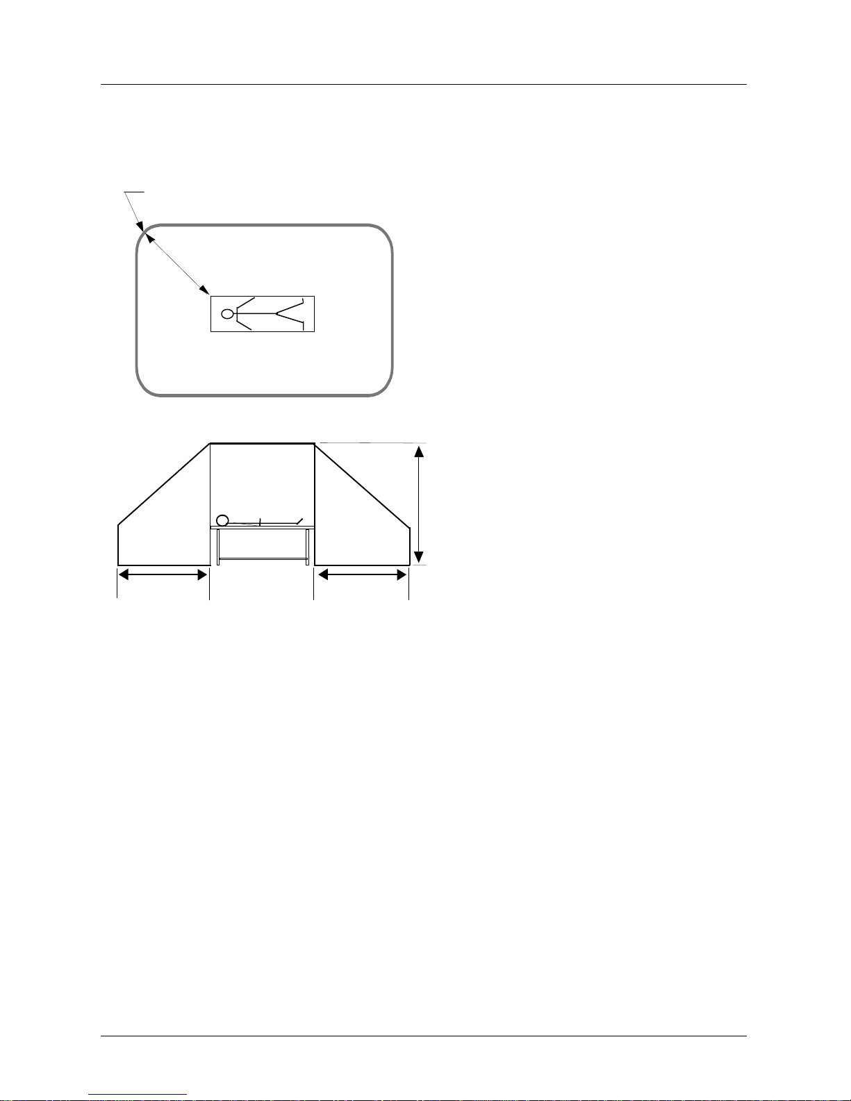
Medical Device Directive (MDD)
m
m
1,83
2,5m
1,83m
1,83
English
This device is not medica l equipment a ccording to EN 6 0 601-1 and mus t therefore not e nter
the Patient Environment as defined in EN 60 601-1-1. The following requirements have to
be met:
1. Distance from devi ce to Pat ien t Cont act Equi pment (see il lustrat ion). H orizon tal = 1,83
metres; Vertical = 2,5 metres above the floor under the patient.
2. Contact of patient and device simultaneously by caregiver not allowed.
3. NO direct electrical connection between device and Patient Contact Equipment is
allowed.
AUTHORISED AGENT:
Manager, Product Safety; Kodak AG; Hedelfingerstr. 54-56; 70327 Stuttgart, GERMANY.
Page 4

Dansk
Denne enhed klacificeres ikke som medicinsk udstyr jævnfør standarden EN 60 601-1 og
må derfor ikke komme i nærheden af patientomgivelserne, som beskrevet i EN 60 601-1-1.
Følgende krav skal være opfyldt:
1. Afstanden fra enheden til p atientlejet (se tegningen). V and ret = 1,83 meter; Lo dret = 2,5
meter over gulvet under patienten.
2. Personalet må ikke berøre enheden og patienten samtidigt.
3. Der må IKKE forekomme direkte elektrisk forbindelse mellem enheden og patientlejet.
AUTORISERET FORHANDLER:
Manager, Product Safety; Kodak AG; Hedelfingerstr. 54-56; 70327 Stuttgart, TYSKLAND
Deutsch
Dieses Gerät ist kein medizinisches Gerät nach dem Standard EN 60 601-1 und darf sich
daher nicht in der Umgebung des Patienten, die durch den Standard EN 60 601-1-1 festgelegt ist, befinden. Die folgenden Anforderungen müssen erfüllt sein:
1. Abstand vom Gerät zum Patient Contact Equipment, d. h. zu mit dem Patienten in
Berührung stehenden Gerätschaften (siehe Abbildung). Horizontal = 1,83 Meter; Vertikal = 2,5 Meter über dem Boden unter dem Patienten.
2. Gleichzeitige Berührung von Patient und Gerät durch das Pflegepersonal nicht zuläs-
sig.
3. KEINE direkte elektrisc he Verbindung zwischen Gerät und Pati ent Cont act Equi pment
zulässig.
AUTORISIERTE VERTRETUNG:
Manager, Produktsicherheit; Kodak AG; Hedelfingerstr. 54-56; 70327 Stuttgart,
DEUTSCHLAND.
Español
Este dispositi vo no constituye un equipo médi co según el estándar EN 60 601 -1, por lo tanto
no necesita cumplir las normas para el entorno del paciente definidas en
EN 60 601-1-1. Deben cumplirse los siguientes requisitos:
1. Distancia del dispositivo al equipo de contacto con el paciente (véase diagrama). Hor-
izontal = 1,83 metros; Vertical = 2,5 metros por encima del suelo debajo del paciente.
2. No debe permitirse el contacto del asistente con el paciente y el dispositivo al mismo
tiempo.
3. NO debe permitirs e la conex ión eléc trica direc ta entre e l disposi tivo y el e quipo de co n-
tacto con el paciente.
AGENTE AUTORIZADO:
Gerente, Seguridad de producto; Kodak AG; Hedelfingerstr. 54-56; 70327 Stuttgart,
ALEMANIA.
Page 5

Français
Ce dispositif n' est p as assimil é à un équip ement méd ical comm e défini p ar l'EN 60 6 01-1 et
ne doit donc pas se conformer aux exigences d'environnement du patient que définit
l'EN 60 601-1-1. Les exigences suivantes doivent être respectées:
1. Distance ent re le dispositif et l'é qui pem en t en con t ac t av ec le p a tie nt (v oir i llu stration):
horizontalement = 1,83 mètres ; verticalement = 2,5 mètres au-dessus du sol sous le
patient.
2. Interdiction stric te au soigna nt d'être simult anémen t en cont act avec le patient et le di s-
positif.
3. INTERDICTION d' établi r une conn exion éle ctrique di recte entre le dispo sitif et l' équipe-
ment en contact avec le patient.
AUTORISATION:
Directeur, Contrôle sécurité; Kodak AG; Hedelfingerstr. 54-56; 70327 Stuttgart,
ALLEMAGNE.
Italiano
Questo disposi tivo non è un 'appa recchiat ura medica le ai sens i di EN 60 601 -1 e quindi n on
deve essere posta in prossimità del paziente, come definito in EN 60 601-1-1. Devono
essere soddisfati i requisiti elencati nel segui to:
1. Distanza tra il dispositivo e le attrezzature a contatto del paziente (vedere la figura).
Orizzonta le = 1,83 metri; V erticale = 2 ,5 metri sopra i l livello del pavimen to del pazi ente.
2. Non deve essere consentito al personale il contatto diretto contemporaneo con il
paziente ed il dispositivo.
3. NON deve esistere alcun contatto elettrico diretto tra il dispositivo e le attrezzature a
contatto del paziente.
AGENTE AUTORIZZATO:
Manager, Sicurezza Prodotto; Kodak AG; Hedelfingerstr. 54-56; 70327 Stuttgart,
GERMANIA.
Lietuviðkai
Ðis prietaisas nëra medicinos prietaisas pagal EN 60 601-1 ir todël privalo nepatekti á
paciento aplinkà, apibrëþtà EN 60 601-1. Bûtina laikytis ðiø reikalavimø:
1. Atstumas nuo prietaisas iki su pacientu kontaktuojanèios árangos (þr. paveikslà): hori-
zontaliai - 1.83 m; vertikaliai - 2.5 m virð grindø, po pacientu.
2. Pacientà priþiûrinèiam asmeniui vienu metu prie paciento ir prie prietaisas liestis
neleidþiama.
3. NELEIDÞIAMAS tiesioginis elektros kontaktas tarp prietaisas ir su pacientu susil-
ieèianèios árangos.
ÁGALIOTASIS ATSTOVAS:
Produkcijos saugos vadybininkas; Kodak AG; Hedelfingerstr. 54-56; 70327 Stuttgart,
VOKIETIJA.
Page 6

Nederlands
Deze app araat i s geen medisc he app ara tuu r volge ns EN 60 601-1 en ma g d aarom nie t bi nnen de behandelingsomgeving van de patiënt staan zoals bepaald is in EN 60 601-1-1. Er
moet aan de volgende eisen worden voldaan:
1. Afstand vanaf apparaat tot behandelinstallatie patiënt (zie afbeelding). Horizontaal =
1,83 meter; Verticaal = 2,5 meter boven de vloer vanaf de vloer onder de patiënt.
2. Gelijktijdig contact met patiënt en apparaat door verzorger is niet toegestaan.
3. Directe elektrische verbinding tussen apparaa t en behandelinstallatie patiënt is NIET
toegestaan.
GEVOLMACHTIGD VERTEGENWOORDIGER:
Manager, Productveiligheid; Kodak AG; Hedelfingerstr. 54-56; 70327 Stuttgart, Duitsland.
Norsk
Denne enheten betegnes i kke som medi sinsk ut styr i henhold ti l EN 60 601-1, og m å derfor
ikke settes inn i pasientmiljø som definert i EN 60 601-1-1. Følgende krav må overholdes:
1. Avstand fra enheten til utstyr i kontakt med pasient (se illustrasjon). Horisontalt = 1,83
meter, vertikalt = 2,5 meter over gulvet under pasienten.
2. Personalet må ikke ha samtidig kontakt med pasient og enheten.
3. INGEN direkte e lek tris k forbindelse mellom enheten og ut sty r i k ontakt med pasient er
tillatt.
AUTORISERT FORHANDLER:
Leder, produktsikkerhet; Kodak AG; Hedelfingerstr. 54-56; 70327 Stuttgart, TYSKLAND.
Português
De dispositiv o aco rdo com o dete rmina do em EN 6 0 601-1 , este proce ssad or não é con siderado equipamento médico e como tal não tem que obedecer às normas definidas em EN
60 601-1-1. Têm que ser cumpridos os seguintes requisitos:
1. Distância do dispositivo ao equipamento de contacto com o paciente (ver ilustração).
Horizontal = 1,83 metros; Vertical = 2,5 metros acima do chão debaixo do paciente.
2. Não é permitido o contacto simultâneo entre o assistente, o paciente e o dispositivo.
3. NÃO é permitida a ligação eléctrica directa entre o dispositivo e a equipa de contacto
com o paciente.
AGENTE AUTORIZADO:
Gerente, Segurança do Produto; Kodak AG; Hedelfingerstr. 54-56; 70327 Stuttgart,
ALEMANHA.
Page 7

Suomeksi
Tämä laite e i ole sairaan hoi tol aitt eis too n kuuluva laite siten kuin st andardissa EN 60 601-1
asia määritellään ja siksi sitä ei tule viedä standardin EN 60 601-1-1 mukaiseen potilasympäristöön. Seuraavat vaatimukset on täytettävä:
1. Etäisyys laitteesta potilaan kanssa kosketuksessa olevaan laitteistoon (ks. piirros).
Vaakatasossa = 1,83 metriä; pystytasossa = 2,5 metriä potilaan alla olevan lattian
yläpuolella.
2. Hoitohenkilö ei saa koskettaa potilasta samanaikaisesti kun hän koskettaa laitetta.
3. Laite EI saa olla s uorassa s ähköises sä kosk etukses sa potilaa n kanssa kosketuk sessa
olevaan laitteistoon.
VALTUUTETTU EDUSTAJA:
Johtaja, Product Safety; Kodak AG; Hedelfingerstr. 54-56; 70327 Stuttgart, SAKSA.
Svenska
Denna enheten utgör ej medicinsk utrustning enligt EN 60 601-1 och får därför ej införas i
patientnära miljö såsom denna definieras i EN 60 601-1-1. Följande krav måste vara uppfyllda:
1. Avstånd från enhete n till u trustni ng med pat ientko nta kt (se fi guren). Ho risont ellt = 1,8 3
m; vertikalt = 2,5 m ovanför golvet under patienten.
2. Vårdgivande person får ej samtidigt vidröra patienten och enheten.
3. INGEN direkt elektrisk förbindelse mellan framkallare och utrustning med patientkon-
takt får enheten.
AUKTORISERAT OMBUD:
Manager , Product Safety ; Kodak AG; Hedelfingerstr . 54-56; D-70327 S tuttgart , TYSKLAND.
Pub. No. 5E2234 Health Imaging
© Eastman Kodak Company, 2 000 EASTMAN KODAK COMPANY
Printed in USA, June 2000 Rochester, New York 14653
Page 8

Page 9

1
Safety
••••••••
In this chapter
Responsibility of the Manufacturer ....................... 1-2
General Information.............................................. 1-3
1-1
Page 10

Safety
Responsibility of the Manufacturer
IMPORTANT: To meet Electromagnetic Compatibility
requirements at a frequency of 50 Hz, the 160 Laser
Imager and the Medical Image Manager 200 were connected to the Power Kit/for KODAK PACS Link Medical
Image Managers, Catalog No. 198 4160. Please refer to
“Safety Standards and Regulatory Approvals” in the Site
Specifications for the KODAK EKTASCAN 160 Laser
Imager, Publication No. 5E2235.
The manuf actur er is re sponsi ble for the effects on safety,
reliability, and performance of the 160 Laser Imager when
the following conditions are followed:
Assembly operations, extensions, readjustments,
modifications or repairs are carried out by persons
authorized by the manufacturer.
The electrical installation of the site complies with the
site specifica tio n requ ir em ents.
Operation of the 160 Laser Imager complies with the
instructions for use in the User Guide.
NOTE: Please refer to the Site Specifications for
the KODAK EKTASCAN 160 Laser Imager,
Publication No. 5E2235, for site preparation
information.
1-2 5E2234 June 2000
Page 11
General Information
DANGER: Read and understand all instructions before using the KODAK EKTASCAN
160 Laser Imager.
Do not use the Laser Imager for direct patient contact.
Do not use the Laser Imager within a 6 ft. radius of an
immobilized patient.
Do not use the Laser Imager in an explosive environ-
ment.
Safety
Use of controls or adjustments or performance of pro-
cedures other than those specified herein may result
in hazardous radiation exposure.
CAUTION: This device is intended for use
only by professional, trained personnel.
5E2234 June 2000 1-3
Page 12
Safety
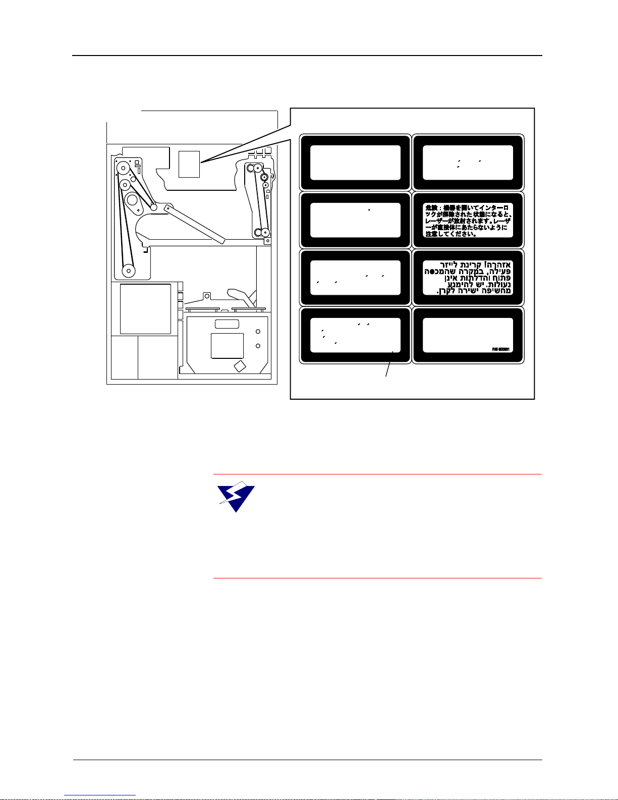
BACK VIEW
H178_0141HCA
H178_0141HC
Laser radiation when open
Danger:
and interlocks defeated. Avoid
direct exposure to beam.
Laserstrahlung bei
Achtung:
geoffnetem Gerat und
a b g e s h a l t e t e n
Sicherheitsvorrichtungen. Setzen
Sie sich nicht direkt dem
Laserstrahl aus.
Attention:
lorsque l’appereil est ouvert et les
verrouillages de securite sont
desactives. Eviter toute exposition
directe au faisceau.
Peligro:
esta abierto y los enclavamientos
estan desactivados. Evite la
exposicion directa al haz.
Rayonnement laser
Radiacion laser cuando
Uwaga: Niewidzialne promieniowanie
laserowe po otwarciu i pokonaniu
zabezpieczen. Unikac wystawiania
sie na bezposrednie dzialanie
promienia lasera.
INVISIBLE LASER DANGER LABEL
1-4 5E2234 June 2000
W ARNING: Danger, avoid laser beam. This
equipment uses an invisible infrared laser.
Laser Radiation can be present when the
machine is operated with the panels off and the interlocks defeated. Avoid direct exposure to the laser
beam.
Page 13

Safety
CAUTION
Remove the wall plug before servicing equipment.
This equipment is operated with hazardous voltage
that can shock, burn, or cause death.
Do not pull the cord from the outlet. Grasp the plug
and pull to disconnect.
Do not operate equipment with a damaged power
cord. Position the power cord so that it will not be
tripped over or accidentally pulled.
Do not use extension cords to power the Laser
Imager. Connect the equipment to grounded outlets.
Refer to the Site Specifications for the KODAK
EKTASCAN 160 Laser Imager, Publication No.
5E2235 for additional details.
This equipment generates, uses, and can radiate
radio frequency energy. If not installed and used in
accordance with the instruction manual, it may cause
interference with radio communications.
This equipment has been tested and found to be
exempt from the limits for a Class A computing device
pursuant to Part 15, Subpart J of FCC Rules. This is
designed to provide reasonable protection against
such interference when operated in a commercial
environment.
Operation of this equipment in a residential
environment is likely to cause interference, in which
case the user, at the user’s own expense, will be
required to take whatever measures may be required
to correct the interference.
5E2234 June 2000 1-5
Page 14
Safety
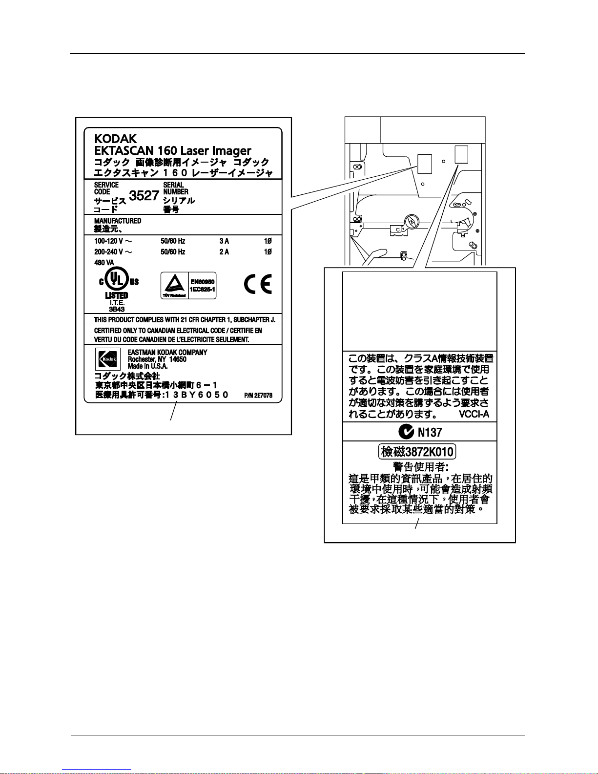
This device complies with the RFI requirements of
EN55011, Class A.
This device complies with Part 15 of the FCC rules.
Operation is subject to the following two conditions:
(1) This device may not cause harmful interference,
and (2) this device must accept any interference
received, including interference that may cause
undesired operation.
This Class A digital apparatus complies with Canadian
ICES-003.
Cet appareil numérique de la classe A est conforme
à la norme NMB-003 du Canada.
H178_0063DCA
H178_0063DC
DATA PLATE LABEL
EMC LABEL
1-6 5E2234 June 2000
Page 15
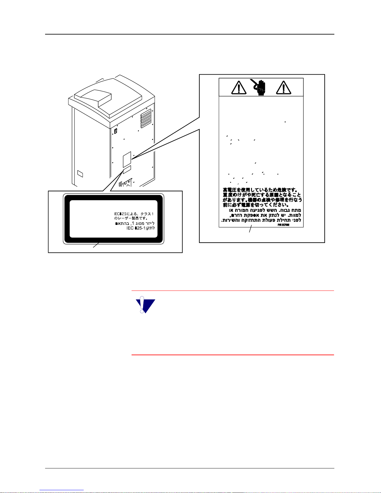
Hazardous Voltage.
Can cause severe injury or death. Disconnect
power supply before servicing machine.
Hochspannung.
Verletzungsund Lebensgefahr. Schalten Sie die
Stromversorgung ab, bevor Sie das Gerat warten.
Tension dangereuse.
Peut provoquer des blessures graves ou la mort.
Debrancher le cordon d’alimentation avant de
proceder a toute operation de maintenance ou
de reparation sur la machine.
Voltaje peligroso.
Puede producir lesiones graves o la muerte.
Desconecte el suministro de corriente antes de
hacer funcionar la maquina.
Niebezpieczne napiecie.
Moze spowodowac powazne obrazenia albo
nawet smierc. Przed wykonywaniem napraw
nalezy odlaczyc zasilanie.
Safety
CLASS 1 LASER PRODUCT
ACCORDING TO IEC 825-1
KLASSE 1 LASER PRODUKT
ENTSPRECHEND IEC 825-1
APPAREIL A RAYONNEMENT
LASER DE CLASSE-1
‘‘PRODCUTO LASER TIPO UNO’’
SEGUN NORMATIVA 825 DE LA C.E.I.-1
CLASS 1 LABEL
PRODUCKT LASEROWY KLASY 1
ZGODNIE IEC 825-1
HAZARDOUS VOLTAGE LABEL
IMPORTANT: The KODAK EKTASCAN 160
Laser Imager is a Class 1 device. To protect the
user against electrical shock, this device complies with the ground requirements as specified in the
KODAK EKSTASCAN Site Specifications for the 160
Laser Imager, Publication No. 5E2235.
H178_0064HCA
H178_0064HC
5E2234 June 2000 1-7
Page 16

Safety
1-8 5E2234 June 2000
Page 17

2
Overview
••••••••
In this chapter
Product Description .............................................. 2-2
System Configuration ........................................... 2-3
Single Input .................................................... 2-3
Multiple Input and Network.............................2-4
Using the Control Panel........................................ 2-5
Features......................................................... 2-8
Screen Types............................................... 2-10
Main Display Screen............................................2-11
Using the “Setup Menu” and “Configure Display”2-14
2-1
Page 18
Overview
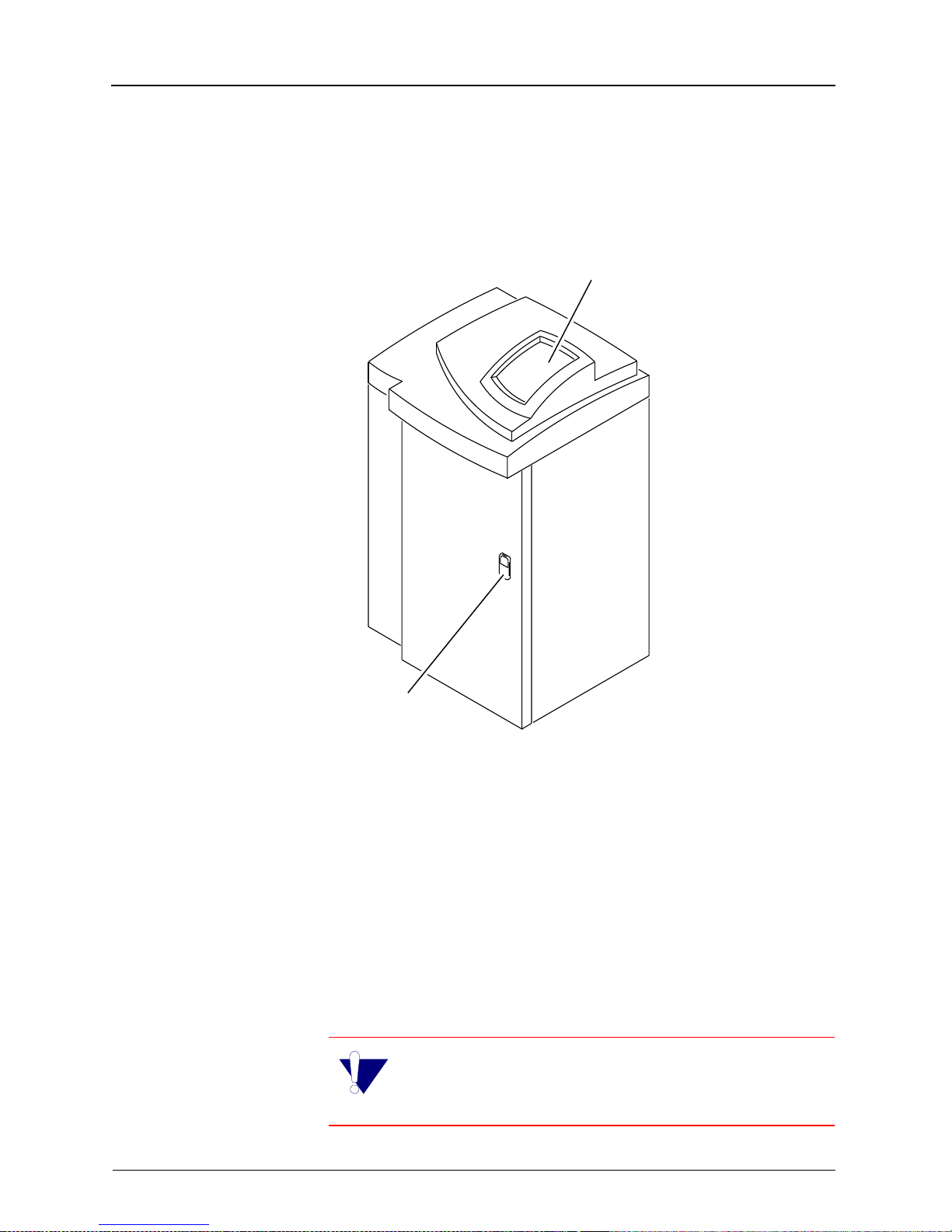
Product Description
160 Laser Imager
Control Panel
ront Door Latch
H178_0008GCA
H178_0008GC
The KODAK EKTASCAN 160 Laser Imager (Laser Imager) is a
high quality di gital laser image r intended for diagnost ic hardcopy
applications. The Laser Imager can be used as a stand-alone
unit (as illustrated above) or with direct docking to a KODAK XOMAT 2000 Processor. The Laser Ima ger use s EIR- 23 (blu ebase) IR film in roomlight loadable 35 x 43 cm (14 x 17 in.) cartridges. The dig ital image d ata for the Las er Imager are prov ided
by a dedicated network connection to the KODAK PACS Link
Medical Image Manager (MIM).
IMPORTANT: See the User Guide for the
KODAK P ACS Link Medical Image Manager 200
Publication No. 5E9764 for more information.
2-2 5E2234 June 2000
Page 19
System Configuration
There are many different system configurations for the
160 Laser Imager. Two examples of system configurations are shown.
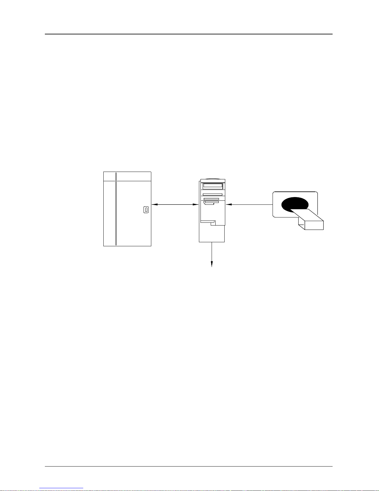
Single Input
160 Laser
Imager
MIM
Overview
Imaging
Device
121BC
100BaseT
Ethernet
Modem Line (optional)
The diagram above illustrates the stand-alone Laser
Imager in a Single Input configuration. In the Single Input
configuration only one Imaging Device is connected to the
KODAK PACS Link Medical Image Manager (MIM). Using
either an internal digital or video interface the MIM
acquires medical images from the Imaging Device.
The MIM formats the input signal (digitizes the video
input, for example) and transfers the data over a
100BaseT Ethernet Network. The operator sends printing
commands to the Laser Imager from the MIM keypad, or
if autofilming is supported, from the Imaging Device.
5E2234 June 2000 2-3
Page 20

Overview
Multiple Input and Network
Imaging
Device
Imaging
Device
MIM
TCP/IP
Imaging
Device
DICOM
Network
H178_0016HC
2000
Processor
160 Laser
Imager
MIM
100baseT
Ethernet
Modem Line (optional)
Imaging
Device
Imaging
Device
The diagram above illustrates the Laser Imager docked to
the KODAK X-OMAT 2000 Processor in a Multiple Input
configuration and in a DICOM (Digital Imaging and Communications in Medicine) Network. The MIM can acquire
DICOM medical images directly from the Imaging Device
over the network or directly connected through a medical
Imaging Device.
2-4 5E2234 June 2000
In the Multiple Input configuration, up to 2 Imaging
Devices and a DICOM Network can be connected to a single MIM. Using an internal video or digital interface, the
MIM formats the input signal (digitizes the video input signal, for example) and transfers the data over a dedicated
100BaseT Ethernet network.
Remote service access may be provided through a
modem in any MIM on the network.
Page 21
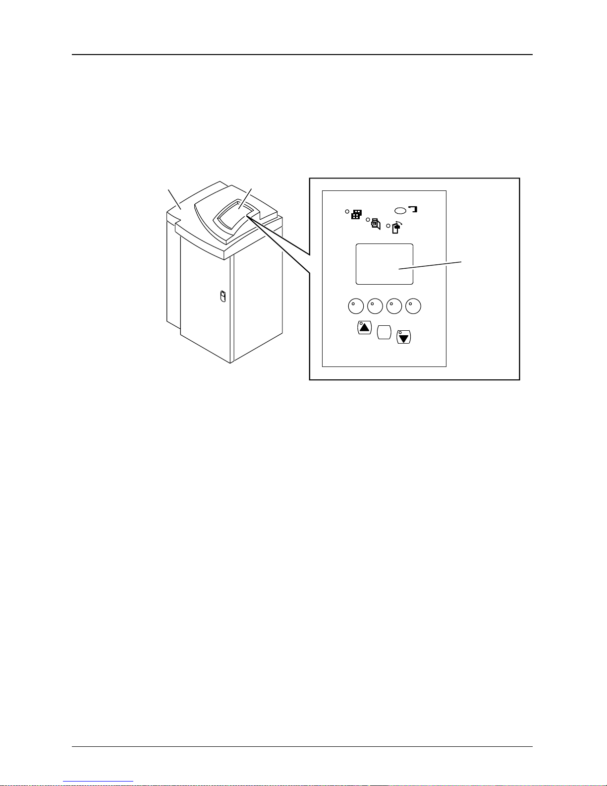
Using the Contro l Panel
The Control Panel allows the user to enter commands and
view the status of the Laser Imager.
Overview
160 Laser Imager
H178_0127BCA
H178_0127BC
Control Panel
x
Main Display
Screen
F2F1 F3 F4
MENU
5E2234 June 2000 2-5
Page 22
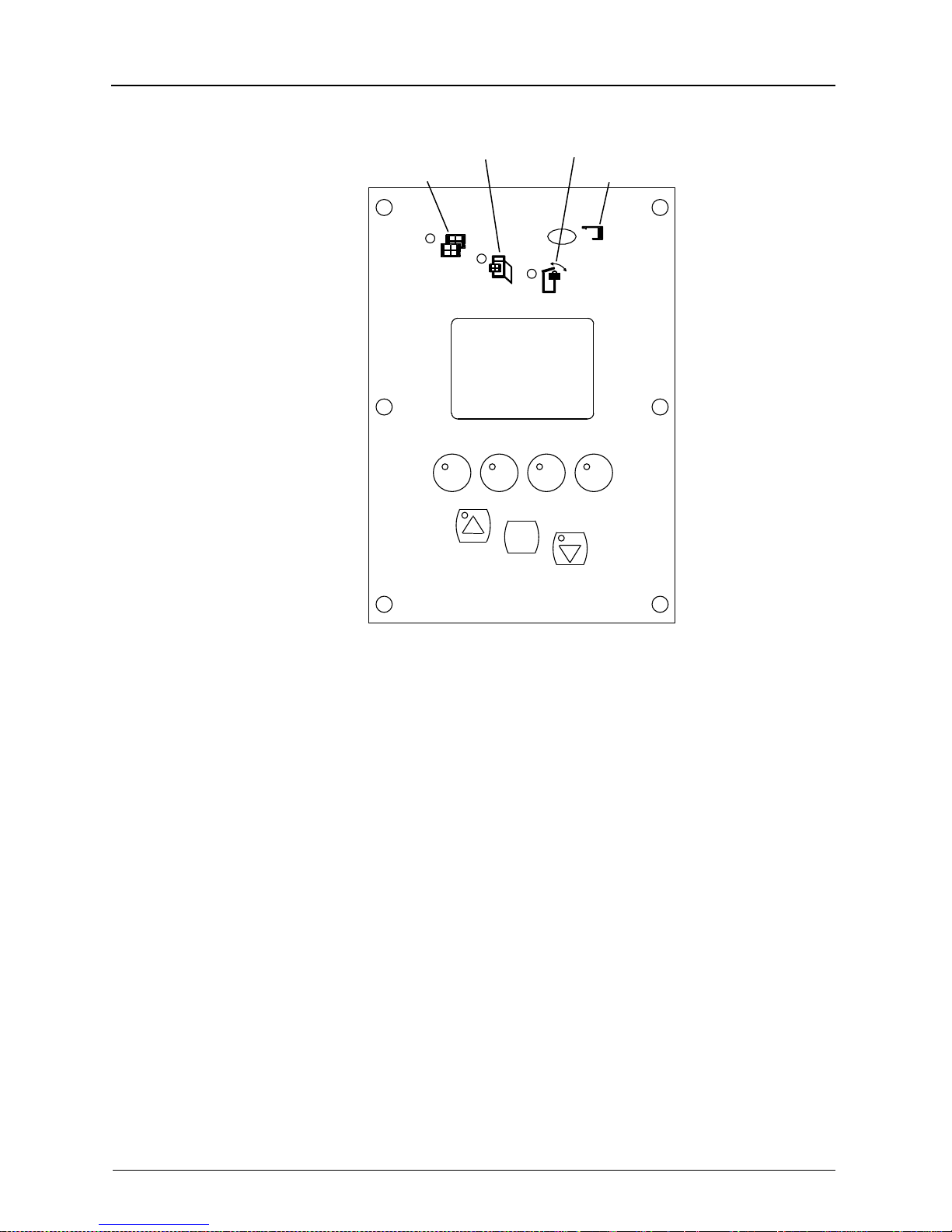
Overview
Indicator Functions
ACCESS FILM SUPPLY
FILM
F2F1 F3 F4
ACCESS RECEIVE
ERROR
x
H178_0017GCA
H178_0017GC
MENU
2-6 5E2234 June 2000
Page 23

Overview
Access
Receive
Access
Film Supply
The LED is on steady when the Receive
Magazine is safe to access. The illumination of the Access Receive Indicator does
not ensure safe access of the Film Supply Cartridge. See the Access Supply
Indicator. WARNING: DO NOT OPEN
THE TOP COVER UNTIL THE ACCESS
RECEIVE INDICAT OR IS ILLUMINATED.
FOGGED FILM WILL RESULT.
The LED is on steady to indicate to the
operator when the Laser Imager film
path, including the film supply cartridge
and the receive magazine, may be safely
accessed. WARNING: DO NOT OPEN
THE FILM SUPPLY UNTIL THE
ACCESS FILM SUPPLY INDICATOR IS
ILLUMINATED. FOGGED FILM WILL
RESULT.
Film When illuminated, indicates to the opera-
tor that the Laser Imager is out of film or
the receive magazine is full.
Error Illuminates whenever a Laser Imager
error occurs. The Error Indicator is turned
off either after the operator has cleared
the error from the Error Recover Screen
or when the Laser Imager software
senses that the Laser Imager has been
accessed.
5E2234 June 2000 2-7
Page 24
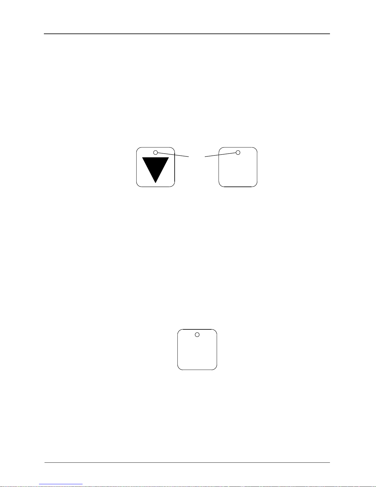
Overview
Features
The Control Panel consists of an LCD display, four F1
through F4 Buttons, Menu Button,
▲ and ▼ Buttons and
four LED functions.
LEDs
Menu
H178_0125ACA
H178_0125AC
The Button LEDs indicate whether the Button is enabled
(illuminated) or disabled (not illuminated).
Menu
2-8 5E2234 June 2000
H178_0126AC
The Menu Button allows you to select a menu option or
complete an operation.
Page 25
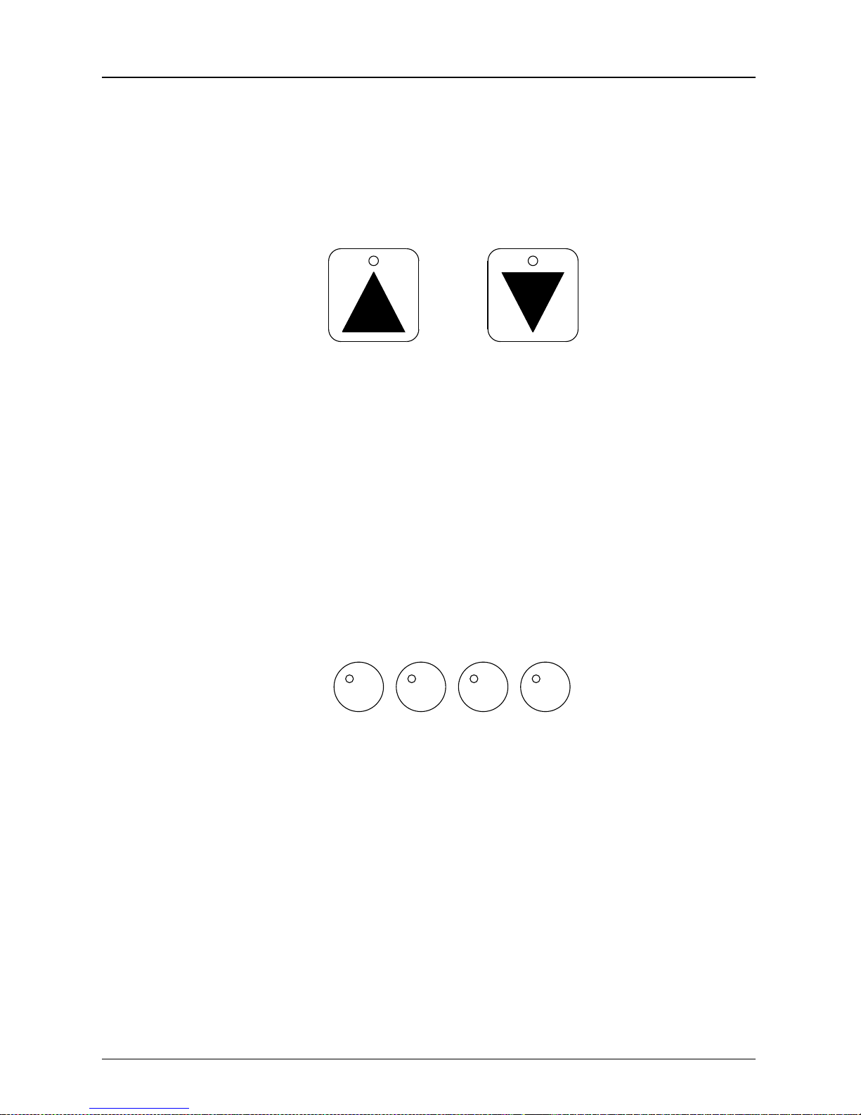
Overview
Each time you press the Menu Button, with the cursor on
an Exit Menu row, the previous screen appears.
H178_0124AC
The Up and Down Arrow Buttons allow you to scroll
through items on the screen. Press the up “
scroll up, press the down “
Press the up “
▲” Button to increment, press the down“▼”
Button to decrement
H178_0132AC
.
▼” Button to scroll down.
F4F3F1 F2
▲” Button to
5E2234 June 2000 2-9
The F1 - F4 Buttons allow you to move directly to the
main display screen by pressing any function button that
is not programmed.
Page 26
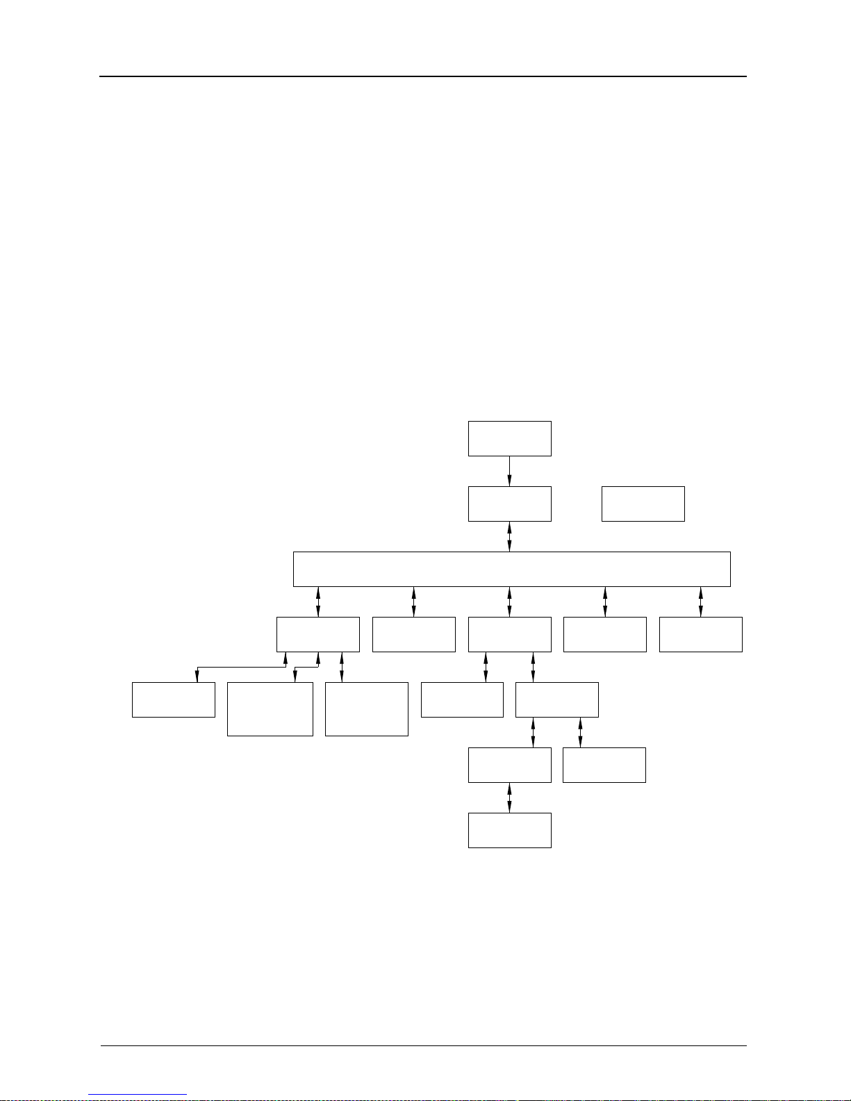
Overview
Screen Types
To move directly to a screen of your choice you have to
program a function button to display to that screen:
Navigate to the screen.
Press and hold the function button for two seconds.
When you hear one beep, the button is programmed.
When you press the function key, the screen displays.
Initialization
Actuations
H178_9001HC
View
Setup Menu
Changing
Decimal Point
Convention
* This screen will appear when docked to a 2000 Processor.
*
Destination
Adjusting
Screen
Contrast
Film
Main Display
Main Menu
Print Cal
Film
Calibrate
Printer
Calibration
Density
Values
Data Entry
Film Supply
Data
Calibration
Recovery
Access
Compute
Error
Access
Receive
2-10 5E2234 June 2000
Page 27

Main Display Screen
The Main Display Screen is displayed most of the time
during normal operation.
Overview
Film Base
Film Destination
H178_0006BCA
H178_0006BC
Ready
Blue Film
Receive
The screen is divided into two sections. The top section of
the screen displays the Laser Imager Status and the bottom section of the screen is the Command and Data Section.
Status Section
34
Command/Data Section
5E2234 June 2000 2-11
Page 28

Overview
Status Section
Initializing
Printing
Not Printing
Ready
Testing
The Laser Imager is in the process of
warming up.
The Laser Imager is in the process of
printing films. The Laser Imager is also
accepting commands and data from the
MIM.
The Laser Imager has stopped printing
films. Any pages that are already in
progress will finish printing. The Laser
Imager accepts commands and data in
this state.
The Laser Imager is ready to print. The
Laser Imager accepts commands and
data in this state.
The Laser Imager is not printing films
from the imaging devices, but is printing
test films or transporting films. The
Laser Imager is accepting commands
and data from the MIM.
Offline
The off li ne co nd i ti o n is sho wn in a r i gh tjustified position on the Status Line.
When offline, the Laser Imager is not
accepting commands or data from the
MIM. The offline condition may exist
during power-up diagnostics and initialization, after certain errors and when
diagnostics are run by a Service Representative.
2-12 5E2234 June 2000
Page 29

Command/Data Section
In the bottom portion of the screen is the data and menu
information.
Data screen: the data displayed on the bottom of the
screen will be preceded by “
ence of more data, the down arrow Button will be
active.
Menu screen: the selection cursor “>” precedes the
active menu item. Undisplayed menu items at the top
and bottom of the screen are indicated by “
“
▼” respectively.
The Main Display Screen displays the following:
Overview
▼” indicating the pres-
▲“ and
Laser Imager Status
The film base and level of the loaded cartridge - if no
cartridge is loaded this line is blank
Possible film destinations with the currently selected
destination highlighted. If the selected destination is
the Receiv e Magazine , the level of film in the R eceive
Magazine is displayed.
IMPORTANT: To disable the Laser Imager during operation select “Access Receive” or
“Access Film Su pply “. W ai t for the stea dy il lumi -
nation of the Indicator then open the Top Cover.
5E2234 June 2000 2-13
Page 30

Overview
Using the “Setup Menu” and
“Configure Display”
Description
Using the screen
The Setup Menu screen allows
viewing actuation count, changing
the number convention for the decimal point and adjusting the display
screen contrast.
Press the “▼” to move the “>” Exit
Menu. The Exit Menu returns to the
Main Menu Screen.
Press the Menu Button to select
your choice. You are automatically
moved to the screen of your
choice.
To exit, use the arrow Button to
move to the Exit Menu.
2-14 5E2234 June 2000
Page 31

3
Operation
••••••••
In this chapter
Start up and Shutdown ......................................... 3-2
System Start up.............................................. 3-2
Laser Imager Startup Screen......................... 3-3
System Shutdown .......................................... 3-4
Loading Film......................................................... 3-5
Film Supply Cartridge..................................... 3-6
Accessing the Receive Magazine......................... 3-8
Store and Print Images....................................... 3-10
Changing the Film Destination............................ 3-10
Viewing the Laser Imager Actuation Count ........3-12
Changing the Decimal Point Convention............3-13
Adjusting the Screen Contrast............................ 3-14
3-1
Page 32

Operation
Start up and Shut do wn
System Start up
2000 Processor
160 Laser Imager
Power Switch
H178_0130BCA
H178_0130BC
Power Switch
IMPORTANT: To avoid poor image quality, do
not send images to the Laser Imager until the
Processor has warmed up. The Processor takes
approximately 30 minutes to warm up.
1. Turn on the Processor. Wait approximately 30 min-
utes for the Processor to warm up.
2. Turn on the Laser Imager.
NOTE: The Laser Imager, as a stand-alone unit,
takes le ss than 10 minu tes to initia lize. When the
Laser Imager is docked to a 2000 Processor, the
Processor must warm up approximately 30 minutes
before initializing the Laser Imager.
3-2 5E2234 June 2000
Page 33

See the Service Manual for the KODAK PACS Link
Medical Image Manager 200, Publication No. 2H7443, for
more start up information.
Laser Imager Startup Screen
Operation
Initializing
Offline
KODAK EKTASCAN
160 Laser Imager
~xxx seconds remain
H178_0122AC
The Laser Imager initially displays this screen with the
prompt “Initializing” at power up. The screen will display
the approximate number of seconds remaining until the
Laser Imager is “Ready”.
5E2234 June 2000 3-3
NOTE: During in it i al iz at i on , no ke ys ar e ac tive.
When initializa tio n is compl ete, the Mai n Menu
Screen will appear.
Page 34

Operation
System Shutdown
1. Wai t for all films to be printed. You ca n look at the MIM
Print Screen to see the source, pages, total films, and
status of the studies in the Print Queue. There are no
films waiting to be printed if the Laser Imager state in
the upper left-hand corner of the Display Screen is
“Ready”.
CAUTION: Do not open the Front Door
when you turn off the Laser Imager. The
Film Supply Cartridge is open. T o prevent
exposure to the film, press “Access Supply” and
wait for the Indicator to light before you turn off
the Laser Imager.
2. Turn off the Laser Imager by moving the Main Power
Switch to the “
0” position.
3-4 5E2234 June 2000
Page 35

Loading Film
Film Types
Operation
IMPORTANT: For film recommendations,
consult your Kodak Sales Representative.
The KODAK EKTASCAN 160 Laser Imager uses KODAK
EKT ASCAN IR Laser Imaging Films. Each box contains
4 cartridges of 125 sheets each.
IMPORTANT: The Film Supply Cartridge for the
Laser Imager is packaged similar to the KODAK
969 Laser Imager. The Laser Imager accepts
only EIR-23 film. Check that you are using the correct film
supply cartridge.
KODAK EKTASCAN IR Laser Imager Film
Film Code Color Description
EIR-23 Bluebase Roomlight Load
5E2234 June 2000 3-5
Page 36

Operation
Film Supply Cartridge
1. Remove the Film Supply Cartridge from the box.
2. From the Main Menu, select “Access Film Supply”
and press the Menu Button. Wait for steady
illumination of the Indicator.
Ready
Exit Menu
Access Receive
>Access Film Supply
Calibrate Printer
Setup Menu
Film Destination
W ARNING: Do not open the Film Supply until
the “Access Film Supply” Indicator is illumi-
nated. Fogged film may result.
3-6 5E2234 June 2000
Page 37

Film Supply
Cartridge
LASER IMAGING FILM
Ektascan
Kodak
Operation
H178_0020HCB
H178_0020HC
Film Supply
3. Lift and rotate the Front Door Latch counterclockwise
to pull open the Front Door.
4. Remove the empty Film Supply Cartridge if present.
5. Slide the cartridge into the Film Supply with the Bar
Code down. See the illustration for the correct orientation of the Film Supply Cartridge.
6. Close the Front Door.
7. Rotate the Front Door Latch clockwise. Push down
the Latch.
5E2234 June 2000 3-7
Page 38

Operation
Accessing the Receive Magazine
Top Cover
Top Cover
Latch
Receive
H178_0011GCB
H178_0011GC
Magazine
WARNING: Do not open the Top Cover until
the “Access Receive Magazine” Indicator is
lit. Fogged film may result.
1. From the Main Menu select “Access Receive” and
press the Menu Button. Wait for steady illumination of
the Indicator.
Ready
Exit Menu
>Access Receive
Access Supply
Calibrate Printer
Film Destination
Setup Menu
3-8 5E2234 June 2000
2. Open the T op Cover and engage the T op Cover Latch.
Page 39

Operation
3. Remove the Receive Magazine by lifting the Handle
and pulling toward you.
4. In a darkroom pull down on the top of each Latch to
open the Receive Magazine and remove the film.
5. Engage each Latch to close the Receive Magazine.
6. Place the Receive Magazine into the Magazine Slot
and verify that the Magazine is securely in place.
7. Disengage the Top Cover Latch and close the Top
Cover.
5E2234 June 2000 3-9
Page 40

Operation
Store and Print Images
See the User Guide for the KODAK PACS Link Medical
Image Manager 200, Publication No. 5E9764, on how to
store and print images.
Changing the Film Destination
Do the following to change the Film Destination from the
Receive Magazine to the Processor, or from the
Processor to the Receive Magazine.
1. From the Main Menu press the ”▼” to move the “>” to
”Film Destination”. Press the Menu Button. The Laser
Imager displays the initial Film Destination Screen.
Ready
Receive Magazine
Last calibrated on
13-Dec-1998 07:24
>Exit Menu
Change Destination
IMPORTANT: For a new film destination,
advance to Step 2. For more information on
calibrating the Laser Imager, see Chapter 4,
“Calibration”.
3-10 5E2234 June 2000
Page 41

Operation
2. Press the “▼” to move the “>” to “Change Destina-
tion”. Pressing the M enu Button toggles the destination. The Calibrate Printer menu item appears on the
screen.
Ready
Processor
Last calibrated on
13-Dec-1998 07:24
Exit Menu
>Change Destination
Calibrate Printer
3. Use the “▲” to move the “>” to Exit Menu. Press the
Menu Button twice to return to the Main Display.
5E2234 June 2000 3-11
Page 42

Operation
Viewing the Laser Imager Actuation Count
1. From the Main Display press the Menu Button. The
Main Menu is displayed.
2. Use the “▼” to move the “>” to “Setup Menu”.
Ready
Exit Menu
Access Receive
Access Supply
Calibrate Printer
>Setup Menu
Film Destination
3. Press the Menu Button. The Setup Menu Screen is
displayed.
Ready
Actuations: 5,567
>Exit Menu
0.00 to 0,00
Screen Contrast (7)
4. Use the “▲” or “▼” to move the “>” to Exit Menu.
Press the Menu Button to return to the Main Display.
3-12 5E2234 June 2000
Page 43

Operation
Changing the Decimal Point Convention
To comply with local conventions, change the convention
for the decimal point from a “.” to a “,”. For example 0.00
to 0,00. To change the convention, do the following:
1. From the Main Display, press the Menu Button. The
Main Menu is displayed.
Ready
>Exit Menu
Access Receive
Access Supply
Calibrate Printer
Setup Menu
Film Destination
2. Use the “▼” to move the “>” to “Setup Menu”. Press
the Menu Button. The Setup Menu Screen is displayed.
Ready
Actuations: 5,567
>Exit Menu
0.00 to 0,00
Screen Contrast (7)
3. Use the “▼” to move the “>” to “0.00 to 0,00”. The
menu selection appears with the currently selected
decimal point in the number to the left of “to”. Pres s
the Menu Button to change to the desired symbol.
4. Use the ”▲” to move the “>” to Exit Menu. Press the
Menu Button 2 times to return to the Main Display.
5E2234 June 2000 3-13
Page 44

Operation
Adjusting the Screen Contrast
1. From the Main Display press the Menu Button. The
Main Menu is displayed.
2. Use the “▼” to move the “>” to “Setup Menu”. Press
the Menu Button. The Setup Menu Screen is displayed.
Ready
Exit Menu
Access Receive
Access Supply
Calibrate Printer
>Setup Menu
Film Destination
3. Use the “▼” to move the “>” to “Screen Contrast”.
Press the Menu Button to select the desired contrast
setting.
Ready
Actuations: 5,567
>Exit Menu
0.00 to 0,00
Screen Contrast (7)
4. Use the ”▲” to move the “>” to Exit Menu. Press the
Menu Button to return to the Main Display.
3-14 5E2234 June 2000
Page 45

4
Calibration
••••••••
In this chapter
Introduction........................................................... 4-2
When to Calibrate............... ...... ....... ...... ...... ....... .. 4-3
Performing the Calibration.................................... 4-4
4-1
Page 46

Calibration
Introduction
Calibration is the method of ensuring consistent image
appearance by compensating for variations in laser
power, differences between film emulsions and other
process variables .
IMPORTANT: When the Laser Imager is docked
to a 2000 Processor, separate calibration is
required for the docked 2000 Processor and the
Receive Magazine.
You will do the following during calibration:
1. If the 2000 Processor is docked to the Laser Imager,
2. Print and process the calibration film.
3. Read the densities of the film and enter the density
4. Compute the Calibration.
Calibration Screens
Calibrate Printer Prints the calibration film and
Calibration Data Allows viewing and modification
select “Film Destination”.
values.
Screen Function
allows access to calibration data
of Laser Imager calibration data
4-2 5E2234 June 2000
Calibration Densities Allows viewing and modification
of Laser Imager calibration densities
Page 47

When to Calibrate
For optimum image quality, the Laser Imager should be
re-calibrated whenever there is any change in the following conditions:
new film emulsion
the processing environment - for example, the
processor chemistry , processor temperature or different processor
Film Box Label - Emulsion Number
Calibration
Kodak
4
Ektascan IR Laser Imaging Film
35 x 43 cm
561992 025 03
LOT
REF
CAT 880-0013
4-125 Sht. Cartridges
EIR
2001-10
H178_0165ACA
H178_0165AC
To determine if the emulsion number has changed, check
the 3-digit emulsion number on the side of the film box.
Emulsion Number
5E2234 June 2000 4-3
Page 48

Calibration
Performing the Calibration
NOTE: This calibration procedure can be per-
formed on a stand-alone Laser Imager or when
docked to a 2000 Processor.
1. From the Main Display, check the selected Film Des-
tination. If it is not the desired destination, change the
selected Film Destination.
2. From the Main Display, press the Menu Button. The
Main Menu is displayed.
Ready
>Exit Menu
Access Receive
Access Film Supply
Calibrate Printer
Setup Menu
Film Destination
3. Use the “▼” to move the ">" to “Calibrate Printer”.
Press the Menu Button. The Calibrate Printer Screen
is displayed.
Ready
Exit Menu
Access Receive
Access Supply
>Calibrate Printer
Setup Menu
Film Destination
The Calibrate Printer Screen displays the calibration
time and date for the currently selected destination.
4-4 5E2234 June 2000
Page 49

Calibration
4. Use the “▼” to select Print Cal Film. Press the
Menu Button.
Ready
Receive Magazine
Last calibrated on
19-Jun-2000 14:24
Exit Menu
>Print Cal Film
Calibration Data
5. The Printing Cal Film Screen is displayed.
Printing Cal Film
Receive Magazine
Last calibrated on
19-Jun-2000 14:02
Exit Menu
Print Cal Film
Calibration Data
6. Retrieve the film from the Receive Magazine or the
Processor Receive Bin. Refer to Chapter 3
“Operation”.
7. Process the film.
5E2234 June 2000 4-5
Page 50

Calibration
Calibration Image
21-step
5
10-step
H178_0038GC
1098761234
IMPORTANT: The 21-step density data on the
Calibration Test Film can be used for process
control.
8. Measure the 10-step density data by using a
Densitometer.
a. Prepare the Densitometer for use.
b. Measure the density at the center of each grey
step on the Calibration Image.
4-6 5E2234 June 2000
c. Record the data.
9. Enter the film densities from the Calibrate Printer
Screen.
Page 51

Calibration
10. Use the “▼” to select “Calibration Data”. Press the
Menu Button. The Calibration Data Screen is dis-
played.
Ready
Receive Magazine
Last calibrated on
13-Dec-1998 07:24
Exit Menu
Print Cal Film
> Calibration Data
11. Use the “▼” to select “Density Values”. Press the
Menu Button. The Calibration Densities Screen is
displayed.
Ready
Receive Magazine
Last Calibrate on
13-Dec-1998 07:24
Exit Menu
>Density Values
Compute Calibration
12. Use the “▼” to select each density to be changed.
Press the Menu Button .
Ready
Calibration Densities
>Exit Menu
1) 0.25
2) 0.32
3) 0.69
4) 1.31
▼ 5) 1.95
5E2234 June 2000 4-7
Page 52

Calibration
13. Press the Menu Button at the density value to be
changed. The cursor will flash, which will allow you to
change the values. Use the “
▼” or “▲“ to change the
value. Press the Menu Button to accept the change.
Ready
Density Step 1
>0.14 _
Exit
Cancel Change
Menu to change
14. Use the “▼” to move the “>” to Exit. Press the Menu
Button.
15. Repeat steps 12 - 14 for all densities to be changed.
16. Use the “▲“ to move the “>” to Exit. Press the Menu
Button to return to the Calibration Densities Screen.
Ready
Receive Magazine
Last Calibrate on
13-Dec-1998 07:24
>Exit
Density Values
Compute Calibration
17. Use the “▼” to select “Compute Calibration”.
18. Press the Menu Button to complete the calibration.
The calibration information is erased from the screen
display, and is replaced by “Computing Film Model”. If
the calibration is not successful, see Chapter 5
“Tro ubleshooting” for more information.
19. Use the “▲“ to move the “>” to Exit. Press the Menu
Button 2 times to return to the Main Menu.
Ready
Receive Magazine
Calibration Complete
13-Dec-1998 07:24
>Exit
Density Values
Compute Calibration
4-8 5E2234 June 2000
Page 53

5
Troubleshooting
••••••••
In this chapter
Overview............................................................... 5-2
Clearing Film Jams............................................... 5-3
Clearing a Film Jam in the Laser Imager ....... 5-3
Clearing a Film Jam in the Processor ............ 5-5
Replacing the Receive Magazine Latches............ 5-6
Error Codes and Messages.................................. 5-7
General Information ....................................... 5-7
Error Recovery............................................. 5-26
Preventive Maintenance..................................... 5-27
Cleaning the 160 Laser Imager.................... 5-27
Replacing the Air Filter................................. 5-28
Streaks on the Film ...................................... 5-29
5-1
Page 54

Troubleshooting
Overview
This chapter will provide suggestions for what to do if
problems arise. After an overview of the path that the film
takes through the Laser Imager, this chapter will give you
guidance for clearing film jams.
In order to clear f ilm jams, you must ope n the Film D oor of
the Laser Imager.
Before opening the Film Door, read the Safety Information
that is provided at the beginning of this User Guide and
note the location of the laser beam in the Laser Imager.
5-2 5E2234 June 2000
Page 55

Clearing Film Jams
Clearing a Film Jam in the Laser Imager
If a film jam occurs during normal operation, the Laser
Imager will stop printing. An Error Message will be displayed on the Control Panel. Follow the instructions on
Page 5-5 to clear the error and return to normal operation.
If the problem persists, record the error message number
and call your Kodak Service Representative.
Troubleshooting
5E2234 June 2000 5-3
Page 56

Troubleshooting
Film Path of the Laser Imager
2000 Processor
Processor Entrance
Upper Film Path
Middle Film Path
Lower Film Path
Exposure Optics Module
Receive Magazine Film Path
Receive Magazine
Picker Assembly
Film Supply
Optics Door Latch
H178_0134HCA
H178_0134HC
Optics Module Door
W ARNING: Do not open the Film Supply until
the “Access Film Supply” Indicator is illuminated. Fogged film will result.
5-4 5E2234 June 2000
Page 57

Troubleshooting
When a Film Jam occurs, do the following:
1. From the Main Menu, press “Access Film Supply”.
Wait for the indicator to illuminate steady before pro-
ceeding.
2. Open the Front Door of the Laser Imager.
3. Open the Top Cover.
4. If necessary, pull the Optics Door Latch out to open
the Optics Door.
5. Check the film path to locate the jam.
6. Carefully remove the film and check that all the films
are removed from the Laser Imager.
7. Empty all the film from the Receive Magazine before
inserting the empty Magazine into the Laser Imager.
This will ensure a correct film count in the Receive
Magazine for the next session.
8. Close the Optics Door.
9. Close the Top Cover and the Front Door.
10. If the film jam persists, call your local Kodak Service
Representative.
Clearing a Film Jam in the Processor
See the User Manual for the KODAK X-OMAT 2000
Processor, Publication Number 7C8770, for more information.
5E2234 June 2000 5-5
Page 58

Troubleshooting
Replacing the Receiv e Magazine Latches
The 2 Receive Magazine Latches can be replaced. Contact your local Kodak Representative to order the
Replacement Latch / for KODAK EKTASCAN 160 Laser
Imager Receive Magazine, Catalog Number 109-3004.
Screwdriver
H178_0133ACA
Latch
1. Insert a screwdriver between the Latch and the
H178_0133AC
Magazine to loosen and remove the Latch.
2. Install the new Latch.
5-6 5E2234 June 2000
Page 59

Error Codes and Messages
General Information
During normal operation, the Laser Imager will provide
feedback to the user . If an error occurs, the LCD displays
an Error Message. See the Error Messages T able for a list
of error messages and suggested action to clear these
error messages.
Wait for the “Access Film Supply” Indicator to illuminate
steadily before opening the Top Cover or the Film Supply.
Troubleshooting
5E2234 June 2000 5-7
Page 60

Troubleshooting
Error Messages
MESSAGE DESCRIPTION ACTION
7001 - 7006
System Software Error
7125
7150
7155 - 7157
7250 - 7251
7260 - 7261
7270
7280 - 7282
7300 - 7302
7343 - 7346
7351
7394 - 7395
7040 - 7043 Mechanical Control Error
1. Press “Access Film
Supply”. Turn off the
Laser Imager.
2. Turn on the Laser
Imager.
3. If the above actions do
not solve the problem,
record the Error Message number displa ye d
and call your Kodak Service Representative.
1. Press "Access Film
Supply".
2. Turn off the Laser
Imager.
3. Turn on the Laser
Imager.
7050 Initialization Error
4. If the above actions do
not solve the problem,
record the Error Message number displa ye d
and call your Kodak Service Representative.
1. Press "Access Film
Supply".
2. Turn off the Laser
Imager.
3. Turn on the Laser
Imager.
4. If the above actions do
not solve the problem,
record the Error Message number displa ye d
and call your Kodak Service Representative.
5-8 5E2234 June 2000
Page 61

Troubleshooting
MESSAGE DESCRIPTION ACTION
7075 CAL Density Error
7076 - 7077
Calibration Error
7320
1. Enter the Density Value
again. See Chapter 4
“Calibration.
2. Calibrate the Laser
Imager, see Chapter 4
“Calibration”.
3. If the above actions do
not solve the problem,
record the Error Message number displa ye d
and call your Kodak Service Representative.
1. Calibrate the Laser
Imager, see Chapter 4,
“Calibration”.
2. If the above action does
not solve the problem,
record the Error Message number displa ye d
and call your Kodak Service Representative.
7078 - 7079 Calibration Software Error
1. Press "Access Film
Supply".
2. Turn off the Laser
Imager.
3. Turn on the Laser
Imager.
4. If the above actions do
not solve the problem,
record the Error Message number displa ye d
and call your Kodak Service Representative.
5E2234 June 2000 5-9
Page 62

Troubleshooting
MESSAGE DESCRIPTION ACTION
7100 - 7102 Image Data Transfer Error
7210 Connection Error
1. Press "Access Film
Supply".
2. Turn off the Laser
Imager.
3. Turn on the Laser
Imager.
4. If the above actions do
not solve the problem,
record the Error Message number displa ye d
and call your Kodak Service Representative.
1. Press "Access Film
Supply".
2. Turn off the Laser
Imager.
3. Turn on the Laser
Imager.
7310
7311
7312
7313
7314
Mechanism Error
4. If the above actions do
not solve the problem,
record the Error Message number displa ye d
and call your Kodak Service Representative.
1. Press "Access Film
Supply".
2. Turn off the Laser
Imager.
3. Turn on the Laser
Imager.
4. If the above actions do
not solve the problem,
record the Error Message number displa ye d
and call your Kodak Service Representative.
5-10 5E2234 June 2000
Page 63

Troubleshooting
MESSAGE DESCRIPTION ACTION
7315 No Cartridge
7316 Cartridge Empty
1. Install the Film Supply
Cartridge. See
Chapter 3, “Film Supply
Cartridge”.
2. If the error is still present,
record the Error Message number displa ye d
and call you Kodak Service Representative.
1. Install the new Film Sup-
ply Cartridge. See Chapter 3, “Film Supply
Cartridge”.
2. If the erro r is still presen t,
record the Error Message number displa ye d
and call your Kodak Service Representative.
7317
7318
7319
7382
7349
Barcode Error
1. Press "Access Film
Supply".
2. Open the Front Door.
3. Install new Film Supply
Cartridge. V erify th at the
correct film is installed,
EIR-23.
4. Close the Front Door.
5. If the above actions do
not solve the problem,
record the Error Message number displa ye d
and call your Kodak Service Representative.
5E2234 June 2000 5-11
Page 64

Troubleshooting
MESSAGE DESCRIPTION ACTION
7321 Clear All Film
7322 Film Jam at Cartridge
1. Press "Access Film
Supply".
2. Open the Front Door.
3. Locate and remove the
film jam. See Chapter 5,
“Clearing a Film Jam”.
4. Close the Front Door.
5. If the above actions do
not solve the problem,
record the Error Message number displa ye d
and call your Kodak Service Representative.
1. Press "Access Film
Supply".
2. Open Front Door.
3. Locate and remove the
film jam in the Film Supply. See Chapter 5,
“Clearing a Film Jam”.
4. Close the Front Door.
5. If the above actions do
not solve the problem,
record the Error Message number displa ye d
and call your Kodak Service Representative.
5-12 5E2234 June 2000
Page 65

Troubleshooting
MESSAGE DESCRIPTION ACTION
7323 Film Jam at Exposure
7324 Film Jam at Transport
1. Press "Access Film
Supply".
2. Open Front Door.
3. Open the Optics Door.
4. Check the Exposure
Optics Module and
remove the film jam. See
Chapter 5, “Clearing a
Film Jam”.
5. Close the Front Door.
6. If the above actions do
not solve the problem,
record the Error Message number displa ye d
and call your Kodak Service Representative.
1. Press "Access Film
Supply".
2. Open Front Door.
3. Check the Lower Film
Path, Middle Film Path
and Upper Film Path to
locate and remove the
film jam. See Chapter 5,
“Clearing a Film Jam”.
4. Close the Front Door.
5. If the above actions do
not solve the problem,
record the Error Message number displa ye d
and call your Kodak Service Representative.
5E2234 June 2000 5-13
Page 66

Troubleshooting
MESSAGE DESCRIPTION ACTION
7325 Film Jam at Unload
1. Press "Access Film
Supply".
2. Open the Front Door.
3. Open the Optics Module
Door.
4. Check the Exposure
Optics Module Film Path
to locate and remove the
film jam. See Chapter 5,
“Clearing a Film Jam”.
5. Close the Optics Module
Door.
6. Close the Front Door.
7. If the above actions do
not solve the problem,
record the Error Message number displa ye d
and call your Kodak Service Representative.
5-14 5E2234 June 2000
Page 67

Troubleshooting
MESSAGE DESCRIPTION ACTION
7326 Cannot Open Cartridge
1. Press "Access Film
Supply".
2. Turn off the Laser
Imager.
3. Open Front Door.
4. Manually rotate the
Rollback Roller to open
the Cartridge.
5. Check the Film Cartridge
for a film jam and remove
the film jam. See Chapter
5, “Clearing a Film Jam”.
6. Close the Front Door.
The top films in the cartridge will be fogged.
7. Turn on the Laser
Imager.
8. If the above actions do
not solve the problem,
record the Error Message number displa ye d
and call your Kodak Service Representative.
5E2234 June 2000 5-15
Page 68

Troubleshooting
MESSAGE DESCRIPTION ACTION
7327 Cannot Close the Cartridge
1. Press "Access Film
Supply".
2. Open Front Door.
3. Check the Film Cartridge
for a film jam and remove
the film jam. See Chapter
5, “Clearing a Film Jam”.
4. Manually rotate the
Rollback Roller to close
the Film Cartridge.
5. Close the Front Door.
The top films in the cartridge will be fogged.
6. If the above actions do
not solve the problem,
record the Error Message number displa ye d
and call your Kodak Service Representative.
7328 Service Override Switch Failure
1. Press "Access Film
Supply".
2. Turn off the Laser
Imager.
3. Turn on the Laser
Imager.
4. If the above actions do
not solve the problem,
record the Error Message number displa ye d
and call your Kodak Service Representative.
5-16 5E2234 June 2000
Page 69

Troubleshooting
MESSAGE DESCRIPTION ACTION
7329 Film Jam at Transport Sensor
1. Press "Access Film
Supply".
2. Open the Front Door.
3. Check the Middle and
Upper path and remove
the film jam.
4. Close the Front Door.
5. If the above actions do
not solve the problem,
record the Error Message number displa ye d
and call your Kodak Service Representative.
5E2234 June 2000 5-17
Page 70

Troubleshooting
MESSAGE DESCRIPTION ACTION
7330 Film Jam at Receive Magazine
1. Press "Access
Receive".
2. Open the Top Cover.
3. Remove the Receive
Magazine.
4. Remove the film jam
without opening the
Receive Magazine
Cover.
5. Process any films in the
Receive Magazine to
ensure a correct film
count in the Receive
Magazine for the next
session.
6. Install the Receive
Magazine.
7. Close the Top Cover.
8. If the above actions do
not solve the problem,
record the Error Message number displa ye d
and call your Kodak Service Representative.
5-18 5E2234 June 2000
Page 71

Troubleshooting
MESSAGE DESCRIPTION ACTION
7331 Film Jam at Processor
1. Press "Access Film
Supply".
2. Open the Front Door.
3. Check the Upper Film
Transport and remove
the film jam.
4. If necessary, open the
Processor Top Cover and
check for a film jam at the
Entrance Roller.
5. Close the Front Door
6. If the above actions do
not solve the problem,
record the Error Message number displa ye d
and call your Kodak Service Representative.
7332 - 7337
7339 - 7342
7350
Optics Error
1. Press "Access Film
Supply".
2. Turn off the Laser
Imager.
3. Turn on the Laser
Imager.
4. If the above actions do
not solve the problem,
record the Error Message number displa ye d
and call your Kodak Service Representative.
5E2234 June 2000 5-19
Page 72

Troubleshooting
MESSAGE DESCRIPTION ACTION
7338 Waiting for Film Model
7347
7348
Diagnostics Error
Diagnostics Error
1. Press “Menu” to con-
tinue.
2. If necessary, press
“Access Film Supply”.
3. Turn off the Laser
Imager.
4. Turn on the Laser
Imager.
5. If the above actions do
not solve the problem,
record the Error Message number displa ye d
and call your Kodak Service Representative.
1. Press "Access Film
Supply".
2. Turn off the Laser
Imager.
3. Turn on the Laser
Imager.
4. If the above actions do
not solve the problem,
record the Error
Message number displayed and call your
Kodak Ser vice Representative.
5-20 5E2234 June 2000
Page 73

Troubleshooting
MESSAGE DESCRIPTION ACTION
7380 The film cartridge is empty
1. Press "Access Film Supply".
2. Install the new Film Supply
Cartridge. See
Chapter 3, “Film Supply
Cartridge”.
3. If the error is still present,
record the Error
Message number displayed and call you Kodak
Service Representative.
7381 The film cartridge is nearly empty There will be a warning when
there are less than 10 films left
in the cartridge. You can
replace the film cartridge at
that time or wait until the Error
7380 indicates the cartridge is
empty.
7389 The receive magazine is nearly full There will be a warning when
there is room for 10 or fewer
films in the Receive Magazine.
A full magazine can hold 50
films. You can empty the
Receive Magazine at that time
or wait until the Error 7390
indicate the Receive Magazine
is full.
7390 The receive magazine is full
1. Press “Access Receive”
and wait for the indicator to
illuminate steady before
proceeding.
2. Open the Top Cover and
remove the Receive
Magaine.
3. Empty the Receive Magazine and process the film.
4. Install the Receive Magazine.
5E2234 June 2000 5-21
Page 74

Troubleshooting
MESSAGE DESCRIPTION ACTION
7392 Film Fogged
7393 Top Cover Open
1. Check that the Front
Door is completely
closed.
2. Run at least 4 films to
eliminate the fogged
films. Do Step 1-Step 3
on page 5-29 to run the
films.
3. If the above actions do
not solve the problem,
record the Error Message number displa ye d
and call your Kodak Service Representative.
1. Check tha t the T op Cover
is completely closed.
2. If the above actions do
not solve the problem,
record the Error Message number displa ye d
and call your Kodak Service Representative.
7426 - 7428 Operator Interface Error
1. Press "Access Film
Supply".
2. Turn off the Laser
Imager.
3. Turn on the Laser
Imager.
4. If the above actions do
not solve the problem,
record the Error Message number displa ye d
and call your Kodak Service Representative.
5-22 5E2234 June 2000
Page 75

Troubleshooting
MESSAGE DESCRIPTION ACTION
7435 Cartridge Not Closed
1. Press "Access Film
Supply".
2. Open Front Door.
3. Check the Film Cartridge
for a film jam and remove
the film jam. See Chapter
5, “Clearing a Film Jam”.
4. Manually rotate the Roll-
back Roll er to close the
Film Cartridge.
5. Close the Front Door.
The top films in the cartridge will be fogged.
6. If the above actions do
not solve the problem,
record the Error Message number displa ye d
and call your Kodak Service Representative.
5E2234 June 2000 5-23
Page 76

Troubleshooting
MESSAGE DESCRIPTION ACTION
7900 Trouble opening the film cartridge
1. Press "Access Film
Supply".
2. Turn off the Laser
Imager.
3. Open Front Door.
4. Manually rotate the Roll-
back Roller to open the
Cartridge.
5. Check the Film Cartridge
for a film jam and remove
the film jam. See Chapter
5, “Clearing a Film Jam”.
6. Close the Front Door.
The top films in the cartridge will be fogged.
7. Turn on the Laser
Imager.
8. If the above actions do
not solve the problem,
record the Error Message number displa ye d
and call your Kodak Service Representative.
5-24 5E2234 June 2000
Page 77

Troubleshooting
MESSAGE DESCRIPTION ACTION
7901 Trouble closing the film cartridge
1. Press "Access Film
Supply".
2. Open Front Door.
3. Check the Film Cartridge
for a film jam and remove
the film jam. See Chapter
5, “Clearing a Film Jam”.
4. Manually rotate the Roll-
back Roll er to close the
Film Cartridge.
5. Close the Front Door.
The top films in the cartridge will be fogged.
6. If the above actions do
not solve the problem,
record the Error Message number displa ye d
and call your Kodak Service Representative.
5E2234 June 2000 5-25
Page 78

Troubleshooting
Error Recovery
The Error Recovery Screen appears when the Laser
Imager detects an error. The screen that is currently displayed is suspended. You will be able to view the error
message(s).
Error Recovery Screen
Not Printing
***ERROR 7900***
07-APR-2000 08:19:47
Trouble Opening the
Film Cartridge
▼xxxx more
The menu items on the Error Recover Screen are:
Log entry title (Error) and a four-digit identifier
(number)
Date and time the error occurred
Up to three lines of description of the log entry
▼xxxx more - indicates how many more errors may
be viewed by pressing the down arrow button. Only
errors that have occurred since the current display of
the Error Recovery screen are available to be viewed.
Use the down arrow button to view the next error, if one
exists. The up arrow button is not active.
Press the Menu Button to exit the screen and return to
the suspended screen.
5-26 5E2234 June 2000
Page 79

Preventive Maintenance
Cleaning the 160 Laser Imager
WARNING: Use caution around openings
and electrical connections. When soil is
removed, wipe external surfaces dry with
clean soft cloth.
Do the following to clean the Laser Imager:
1. Turn off the Laser Imager and disconnect the Power
Cord.
Troubleshooting
2. Immerse a clean, soft cloth in an appropriate non-
abrasive cleaning solution.
3. Wring cloth to remove excess fluid.
4. Wipe the external surfaces free of soil.
5E2234 June 2000 5-27
Page 80

Troubleshooting
Replacing the Air Filter
Optics
Module
Door
H178_0065ACC
H178_0065AC
Air Filter
NOTE: It is recommended that you replace the
Air Filter once a year.
Every six months it is recommended that you carefully remove the Air Filter and rotate the Air Filter 180°. Do not change the direction of the Air
Filter when you install it back in the Laser Imager. This will prevent dust
from accumulating in the Laser Imager. Do the following to access the
Air Filter.
1. From the Main Menu, press “Access Film Supply”.
Wait for the indicator to illuminate steady before proceeding.
2. Turn off the Laser Imager.
3. Open the Front Door of the 160 Laser Imager.
4. Open the Optics Module Door.
5. Remove the Air Filter and replace if necessary.
Contact Kodak Distribution to order a new Air Filter/
for KODAK EKTASCAN 160 Laser Imager Catalog
Number 116-1272.
5-28 5E2234 June 2000
6. Close the Front Door.
7. Turn on the Laser Imager.
Page 81

Streaks on the Film
Streaks can be caused by debris on the Processor Rollers. This can occur when the system is inactive. To eliminate the streaks, run 3 films to the Processor before
normal operation.
1. From the Main Display, press the Menu Button. The
2. Use the “▼” to move the ">" to “Calibrate Printer”.
Troubleshooting
IMPORTANT: Do not use this film for calibrating
the Laser Imager. This procedure is to be done
only to eliminate streaks on the film.
Main Menu is displayed.
Press the Menu Button. The Calibrate Printer Screen
is displayed.
The Calibrate Printer Screen displays the calibration
time and date for the currently selected destination.
Ready
Exit Menu
Access Receive
Access Supply
>Calibrate Printer
Setup Menu
Film Destination
3. Use the “▼” to select Print Cal Film. Press the
Menu Button.
Ready
Processor
Last calibrated on
13-Dec-1998 07:24
Exit Menu
>Print Cal Film
Calibration Data
5E2234 June 2000 5-29
4. Retrieve the film from the Processor Receive Bin.
5. Return to normal operation.
Page 82

Troubleshooting
5-30 5E2234 June 2000
Page 83

6
Glossary
••••••••
100BaseT
Calibration
Default
Density
DICOM
D-Max
D-Min
Ethernet
100 MHz/baseband/twisted pair. IEEE standard for 24 gauge,
unshielded twisted pair Ethernet.
A process of adapting the Laser Imager to compensate for variations in the laser power, the film and processing conditions in
order to produce consistent image quality.
A preset value that is automatically assigned to a filed/parameter when no value is specified.
A measure of how black the film is.
The Digital Imaging and Communications in Medicine imaging
standard.
The maximum optical density found on a film.
The minimum optical density found on a film in an unexposed
region.
A passive coaxial cable that transmits digital signals for a net-
work in which the interconnections contain active elements.
Image
Imaging Device
IP Address
LAN
Laser
Each picture that you take of a patient through an imaging
device is called an image.
A generic term for the imaging system (imaging device) that
may include the scanner, imaging computer, and operator
workstation.
Internet Protocol. IP part of the TCP/IP protocol, which routes a
message across networks.
Local Area Network. A combination of computer hardware and
software that interconnects numerous computers and peripherals to provide communication and access to shared data.
Light Amplification by Stimulated Emission of Radiation.
6-1
Page 84

Glossary
Menu
MIM
Option
Prompt
RJ-45
Screen
Scroll bar
TCP/IP
A list of related options that you select to perform an action.
KODAK Medical Image Manager
A function that is listed on a menu that performs a certain
action.
Symbol, text or questions which asks/allows a user to enter a
command or response.
Eight wire modular connectors for Ethernet twisted-pair wiring.
The visible area on the display of a data terminal.
Located on a screen that contains a list of items, the scroll bar
shows the position of the items relative to the entire list.
Transmission Control Protocol/Internet Protocol. Set of commu-
nication protocols developed for the Defense Advanced
Research Projects Agency (DARPA) to connect dissimilar systems. The TCP protocol controls the transfer of the data, and
the IP protocol provides the routing mechanism.
Throughput
Twisted Pair
Wiring
The number of sheets of film that can be printed in one hour.
Wiring used in telephone systems and many networks. It con-
sists of a pair of copper wires twisted around each other to
counteract the effects of noise. Commonly used in lieu of coaxial Ethernet in network applicati ons . Usuall y uns hi eld ed; however, the more expensive shielded version supports greater
distance with less risk of electrical interference.
UTP
Unshielded Twisted Pair. See Twisted Pair Wiring.
Publication History
Print
Date
6/27/00 5E2234 2662-011 All om3527book_1 _ jun00 First Printing
9/15/00 5E2234 2662-050 4-7, 4-8
Pub.
No.
ECO No. Affected
Pages
5-21, 5-22
6-1, 6-2
File Name Notes
om3527book_ 1 _ jun00 Internal Page
Replacements
6-2 5E2234 June 2000
 Loading...