

Kodak Ektascan 1220 Service manual
Publication No. SM3226-1
Supersedes SM3226-1
SERVICE MANUAL
for the
Kodak Ektascan 1120 LASER PRINTER
29AUG97
10FEB97
HEALTH IMAGING
H129_0710AC
© Eastman Kodak Company
PLEASE NOTE The information contained herein is based on the experience and knowledge relating to the
subject matter gained by Eastman Kodak Company prior to publication.
No patent license is granted by this information.
Eastman Kodak Company reserves the right to change this information without notice, and
makes no warranty, express or implied, with respect to this information. Kodak shall not be
liable for any loss or damage, including consequential or special damages, resulting from any
use of this information, even if loss or damage is caused by Kodak’s negligence or other fault.
This equipment includes parts and assemblies sensitive to damage from electrostatic
discharge. Use caution to prevent damage during all service procedures.
Important
Use qualified personnel to service this equipment.
Warning
DANGER - Infrared Laser Beam is not visible. Laser radiation when open, avoid direct exposure to infrared
beam. Use of controls or adjustments or performance of procedures other than those specified herin may result in
hazardous radiation exposure.
2 29AUG97 – SM3226-1

ge
Table of Contents
Description Pa
Service Requirements . . . . . . . . . . . . . . . . . . . . . . . . . . . . . . . . . . . . . . . . . . . . . . . . . . . . 1-1
Safety. . . . . . . . . . . . . . . . . . . . . . . . . . . . . . . . . . . . . . . . . . . . . . . . . . . . . . . . . . . . . . 1-2
Special Tools. . . . . . . . . . . . . . . . . . . . . . . . . . . . . . . . . . . . . . . . . . . . . . . . . . . . . . . . 1-3
Removals . . . . . . . . . . . . . . . . . . . . . . . . . . . . . . . . . . . . . . . . . . . . . . . . . . . . . . . . . . . . . . 2-1
Covers . . . . . . . . . . . . . . . . . . . . . . . . . . . . . . . . . . . . . . . . . . . . . . . . . . . . . . . . . . . . . 2-2
Right, Left and Back Control Unit Covers. . . . . . . . . . . . . . . . . . . . . . . . . . . . . . 2-2
Circuit Boards . . . . . . . . . . . . . . . . . . . . . . . . . . . . . . . . . . . . . . . . . . . . . . . . . . . . . . . 2-7
Memory Board/6MB or 20MB. . . . . . . . . . . . . . . . . . . . . . . . . . . . . . . . . . . . . . . 2-7
Control Unit Components . . . . . . . . . . . . . . . . . . . . . . . . . . . . . . . . . . . . . . . . . . . . . . 2-26
Exhaust Fans . . . . . . . . . . . . . . . . . . . . . . . . . . . . . . . . . . . . . . . . . . . . . . . . . . . . 2-26
Image Unit Components . . . . . . . . . . . . . . . . . . . . . . . . . . . . . . . . . . . . . . . . . . . . . . . 2-29
Optical Unit. . . . . . . . . . . . . . . . . . . . . . . . . . . . . . . . . . . . . . . . . . . . . . . . . . . . . 2-29
Front Control Unit Cover . . . . . . . . . . . . . . . . . . . . . . . . . . . . . . . . . . . . . . . . . . 2-2
Right and Back Image Unit Covers . . . . . . . . . . . . . . . . . . . . . . . . . . . . . . . . . . 2-3
Left Image Unit Cover . . . . . . . . . . . . . . . . . . . . . . . . . . . . . . . . . . . . . . . . . . . . 2-3
Sequence Board Shield . . . . . . . . . . . . . . . . . . . . . . . . . . . . . . . . . . . . . . . . . . . . 2-4
Supply Magazine Door, Receive Magazine Door, and User Access Door. . . . . 2-4
Top Cover . . . . . . . . . . . . . . . . . . . . . . . . . . . . . . . . . . . . . . . . . . . . . . . . . . . . . . 2-5
Right Inside Cover . . . . . . . . . . . . . . . . . . . . . . . . . . . . . . . . . . . . . . . . . . . . . . . 2-6
Left Inside Cover . . . . . . . . . . . . . . . . . . . . . . . . . . . . . . . . . . . . . . . . . . . . . . . . 2-6
System Controller Board . . . . . . . . . . . . . . . . . . . . . . . . . . . . . . . . . . . . . . . . . . 2-8
Print Controller Board . . . . . . . . . . . . . . . . . . . . . . . . . . . . . . . . . . . . . . . . . . . . 2-10
Driver Board . . . . . . . . . . . . . . . . . . . . . . . . . . . . . . . . . . . . . . . . . . . . . . . . . . . . 2-12
JUMPERS . . . . . . . . . . . . . . . . . . . . . . . . . . . . . . . . . . . . . . . . . . . . . . . . . . 2-13
SWITCHES. . . . . . . . . . . . . . . . . . . . . . . . . . . . . . . . . . . . . . . . . . . . . . . . . 2-13
The Replacement of a Driver Board with a Universal Driver Board . . . . . 2-14
2-Phase Pulse Motor Driver Boards (2PMD) . . . . . . . . . . . . . . . . . . . . . . . . . . . 2-17
5-Phase Pulse Motor Driver Boards (5PMD) . . . . . . . . . . . . . . . . . . . . . . . . . . . 2-18
Sequence Board . . . . . . . . . . . . . . . . . . . . . . . . . . . . . . . . . . . . . . . . . . . . . . . . . 2-19
Slow Scan Motor Board . . . . . . . . . . . . . . . . . . . . . . . . . . . . . . . . . . . . . . . . . . . 2-22
Laser Diode Power Supply Board . . . . . . . . . . . . . . . . . . . . . . . . . . . . . . . . . . . 2-23
Backplane Board . . . . . . . . . . . . . . . . . . . . . . . . . . . . . . . . . . . . . . . . . . . . . . . . 2-25
Intake Fans . . . . . . . . . . . . . . . . . . . . . . . . . . . . . . . . . . . . . . . . . . . . . . . . . . . . . 2-27
Main Power Supply . . . . . . . . . . . . . . . . . . . . . . . . . . . . . . . . . . . . . . . . . . . . . . 2-28
Optical Unit Components . . . . . . . . . . . . . . . . . . . . . . . . . . . . . . . . . . . . . . . . . . 2-33
R Transportation Roller Assembly . . . . . . . . . . . . . . . . . . . . . . . . . . . . . . . . . . . 2-34
S Transportation Roller Assembly . . . . . . . . . . . . . . . . . . . . . . . . . . . . . . . . . . . 2-35
Outlet Guide Plate Assembly . . . . . . . . . . . . . . . . . . . . . . . . . . . . . . . . . . . . . . . 2-36
Slow Scan and Encoder Assembly . . . . . . . . . . . . . . . . . . . . . . . . . . . . . . . . . . . 2-39
Slow Scan Assembly Components . . . . . . . . . . . . . . . . . . . . . . . . . . . . . . . . . . . 2-41
Supply Magazine Open/Close Assembly with Separation Unit . . . . . . . . . . . . . 2-42
Supply Magazine Open/Close Assembly Components . . . . . . . . . . . . . . . . . . . 2-44
Separation Assembly . . . . . . . . . . . . . . . . . . . . . . . . . . . . . . . . . . . . . . . . . . . . . 2-44
Separation Assembly Components . . . . . . . . . . . . . . . . . . . . . . . . . . . . . . . . . . . 2-46
Receive Magazine Open/Close Assembly . . . . . . . . . . . . . . . . . . . . . . . . . . . . . 2-48
R Magazine Storing Case . . . . . . . . . . . . . . . . . . . . . . . . . . . . . . . . . . . . . . . . . . 2-49
Locating Film Transportation Components . . . . . . . . . . . . . . . . . . . . . . . . . . . . 2-51
Receive Roller Motor . . . . . . . . . . . . . . . . . . . . . . . . . . . . . . . . . . . . . . . . . . . . . 2-52
Transport Roller Motor . . . . . . . . . . . . . . . . . . . . . . . . . . . . . . . . . . . . . . . . . . . 2-53
Supply Roller Motor . . . . . . . . . . . . . . . . . . . . . . . . . . . . . . . . . . . . . . . . . . . . . . 2-54
SM3226-1 – 29AUG97 –3

SERVICE MANUAL
Diagnostic Check Procedures . . . . . . . . . . . . . . . . . . . . . . . . . . . . . . . . . . . . . . . . . . . . . 3-1
Setting up the Optical Power Meter . . . . . . . . . . . . . . . . . . . . . . . . . . . . . . . . . . . . . . 3-2
Measuring the Laser Power. . . . . . . . . . . . . . . . . . . . . . . . . . . . . . . . . . . . . . . . . . . . . 3-4
Checking Vacuum Pressure . . . . . . . . . . . . . . . . . . . . . . . . . . . . . . . . . . . . . . . . . . . . 3-10
Operation Adjustments . . . . . . . . . . . . . . . . . . . . . . . . . . . . . . . . . . . . . . . . . . . . . . . . . . 4-1
Calibration. . . . . . . . . . . . . . . . . . . . . . . . . . . . . . . . . . . . . . . . . . . . . . . . . . . . . . . . . . 4-2
Overview. . . . . . . . . . . . . . . . . . . . . . . . . . . . . . . . . . . . . . . . . . . . . . . . . . . . . . . 4-2
When to Calibrate . . . . . . . . . . . . . . . . . . . . . . . . . . . . . . . . . . . . . . . . . . . . . . . 4-3
Calibrating the Printer . . . . . . . . . . . . . . . . . . . . . . . . . . . . . . . . . . . . . . . . . . . . 4-4
Measuring and Entering Density Data . . . . . . . . . . . . . . . . . . . . . . . . . . . . . . . . 4-6
Using a Stand-alone DENSITOMETER . . . . . . . . . . . . . . . . . . . . . . . . . . . . 4-6
Calibration Errors . . . . . . . . . . . . . . . . . . . . . . . . . . . . . . . . . . . . . . . . . . . . . . 4-7
Using the Kodak Process Control DENSITOMETER as a Stand-alone
DENSITOMETER . . . . . . . . . . . . . . . . . . . . . . . . . . . . . . . . . . . . . . . . . . . . . 4-9
Checking Stored Calibration Settings . . . . . . . . . . . . . . . . . . . . . . . . . . . . . . 4-11
Recovering from a Calibration Error . . . . . . . . . . . . . . . . . . . . . . . . . . . . . . . . . 4-12
Tone Scaling . . . . . . . . . . . . . . . . . . . . . . . . . . . . . . . . . . . . . . . . . . . . . . . . . . . 4-13
Checking Film Transport . . . . . . . . . . . . . . . . . . . . . . . . . . . . . . . . . . . . . . . . . . 4-14
Setting Film Density - Beam Splitter Pulse Settings . . . . . . . . . . . . . . . . . . . . . 4-16
Printing a Flat Field Image . . . . . . . . . . . . . . . . . . . . . . . . . . . . . . . . . . . . . . . . . 4-21
CES Hidden Mode Setup Procedure . . . . . . . . . . . . . . . . . . . . . . . . . . . . . . . . . 4-22
Adjustment of the Right and Left Film Guides . . . . . . . . . . . . . . . . . . . . . . . . . 4-24
Electrical Adjustments . . . . . . . . . . . . . . . . . . . . . . . . . . . . . . . . . . . . . . . . . . . . . . . . . . 5-1
Circuit Boards . . . . . . . . . . . . . . . . . . . . . . . . . . . . . . . . . . . . . . . . . . . . . . . . . . . . . . . 5-2
Driver Board - Versions 1, 2, & 3 and Serial No. Range 500025-500389 . . . . . 5-2
DC/DC Converter Output Voltage . . . . . . . . . . . . . . . . . . . . . . . . . . . . . . . 5-2
Clock Frequency for Electromagnetic Pump . . . . . . . . . . . . . . . . . . . . . . . 5-4
Film Sensor Adjustments . . . . . . . . . . . . . . . . . . . . . . . . . . . . . . . . . . . . . . 5-6
Emitter Intensity of Film Sensors IL1, IL2, and IL3 . . . . . . . . . . . . . . . . . 5-7
Output Voltage for Receivers PT1, PT2, and PT3 . . . . . . . . . . . . . . . . . . . 5-9
Temporary Emitter Pulse Cycle . . . . . . . . . . . . . . . . . . . . . . . . . . . . . . . . . 5-13
No Film Signal Holding Time . . . . . . . . . . . . . . . . . . . . . . . . . . . . . . . . . . 5-15
Permanent Emitter Pulse Cycle. . . . . . . . . . . . . . . . . . . . . . . . . . . . . . . . . . 5-17
Emitter Pulse Duty Ratio for IL1, IL2, and IL3 . . . . . . . . . . . . . . . . . . . . . 5-19
Driver Board - Versions 4, 5, 6 & Universal and Serial No. Range 500390-500898,
600133-600306 . . . . . . . . . . . . . . . . . . . . . . . . . . . . . . . . . . . . . . . . . . . . . . . 5-21
DC/DC Converter Output Voltage . . . . . . . . . . . . . . . . . . . . . . . . . . . . . . . 5-21
Clock Frequency for Electromagnetic Pump . . . . . . . . . . . . . . . . . . . . . . . 5-22
Film Sensor Adjustments . . . . . . . . . . . . . . . . . . . . . . . . . . . . . . . . . . . . . . 5-24
Emitter Intensity of Film Sensors IL1, IL2, and IL3 . . . . . . . . . . . . . . . . . 5-25
Output Voltage for Receivers PT1, PT2, and PT3 . . . . . . . . . . . . . . . . . . . 5-27
No Film Signal Holding Time . . . . . . . . . . . . . . . . . . . . . . . . . . . . . . . . . . 5-31
Permanent Emitter Pulse Cycle . . . . . . . . . . . . . . . . . . . . . . . . . . . . . . . . . 5-35
Emitter Pulse Duty Ratio for Sensors IL1, IL2, and IL3 . . . . . . . . . . . . . . 5-38
Driver Board - Versions 6 & Higher and Serial No. Range 500899-present, 600307-
present . . . . . . . . . . . . . . . . . . . . . . . . . . . . . . . . . . . . . . . . . . . . . . . . . . . . . . 5-41
DC/DC Converter Output Voltage . . . . . . . . . . . . . . . . . . . . . . . . . . . . . . . 5-41
Film Sensor Adjustments . . . . . . . . . . . . . . . . . . . . . . . . . . . . . . . . . . . . . . 5-42
Output Voltage for Receivers PT1, PT2, and PT3 . . . . . . . . . . . . . . . . . . . 5-43
Emitter Pulse Duty Ratio for Sensors IL1, IL2, and IL3 . . . . . . . . . . . . . . 5-47
Sequence Board . . . . . . . . . . . . . . . . . . . . . . . . . . . . . . . . . . . . . . . . . . . . . . . . . 5-48
Beam Detector Signal Offset Voltage . . . . . . . . . . . . . . . . . . . . . . . . . . . . 5-48
5-Phase Pulse Motor Boards for the Transport Motor Voltages (5PMD) . . . . . 5-52
2-Phase Pulse Motor Board (2PMD), Slide Base Motor Voltage . . . . . . . . . . . 5-57
Laser Diode Control Board . . . . . . . . . . . . . . . . . . . . . . . . . . . . . . . . . . . . . . . . 5-60
Setting Laser Diode Control for D-Min . . . . . . . . . . . . . . . . . . . . . . . . . . . 5-60
Fluctuation of the Laser Diode Reference Current . . . . . . . . . . . . . . . . . . 5-64
Control Panel Board . . . . . . . . . . . . . . . . . . . . . . . . . . . . . . . . . . . . . . . . . . . . . . 5-68
–4 29AUG97 – SM3226-1

Sensors. . . . . . . . . . . . . . . . . . . . . . . . . . . . . . . . . . . . . . . . . . . . . . . . . . . . . . . . . . . . . 5-70
Sucker Pad Height . . . . . . . . . . . . . . . . . . . . . . . . . . . . . . . . . . . . . . . . . . . . . . . . 5-70
PHF Film Suction Sensor . . . . . . . . . . . . . . . . . . . . . . . . . . . . . . . . . . . . . . . . . . 5-74
PHS1 S Magazine Open Sensor . . . . . . . . . . . . . . . . . . . . . . . . . . . . . . . . . . . . . 5-76
PHS2 S Magazine Close Sensor . . . . . . . . . . . . . . . . . . . . . . . . . . . . . . . . . . . . . 5-78
PH3 S Magazine Door Sensor . . . . . . . . . . . . . . . . . . . . . . . . . . . . . . . . . . . . . . 5-80
CHS1 Slide Base Position Sensor Reference Position . . . . . . . . . . . . . . . . . . . . 5-81
PHR1 R Magazine Open Sensor . . . . . . . . . . . . . . . . . . . . . . . . . . . . . . . . . . . . 5-86
PHR2 R Magazine Close Sensor . . . . . . . . . . . . . . . . . . . . . . . . . . . . . . . . . . . . 5-88
PH4 R Magazine Door Sensor . . . . . . . . . . . . . . . . . . . . . . . . . . . . . . . . . . . . . . 5-90
Receive Side Stopper Position . . . . . . . . . . . . . . . . . . . . . . . . . . . . . . . . . . . . . . 5-91
CHT1 Supply Roller Position Sensor . . . . . . . . . . . . . . . . . . . . . . . . . . . . . . . . . 5-93
CHT2 Receive Roller Position Sensor . . . . . . . . . . . . . . . . . . . . . . . . . . . . . . . . 5-97
Preventive Maintenance Checklist . . . . . . . . . . . . . . . . . . . . . . . . . . . . . . . . . . . . . . . . . 6-1
SM3226-1 – 29AUG97 –5

SERVICE MANUAL
–6 29AUG97 – SM3226-1

Section 1: Service Requirements
ge
Table of Contents
Description Pa
Safety. . . . . . . . . . . . . . . . . . . . . . . . . . . . . . . . . . . . . . . . . . . . . . . . . . . . . . . . . . . . . . 1-2
Special Tools. . . . . . . . . . . . . . . . . . . . . . . . . . . . . . . . . . . . . . . . . . . . . . . . . . . . . . . . 1-3
Service Requirements
SM3226-1 – 29AUG97 1–1

SERVICE MANUAL
H129_0800AC
H129_0800ACA
LABELS
LASER SAFETY
Safety
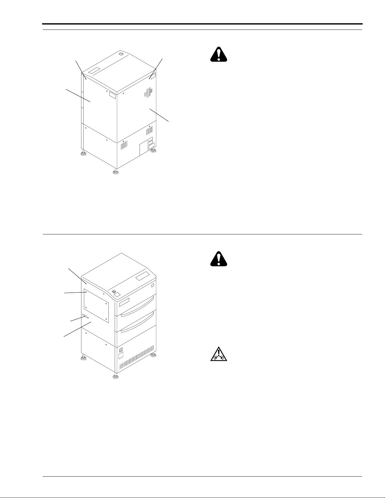
Use the following figures to locate the LASER SAFETY LABELS on the LASER PRINTER. For your safety,
warnings are also included in the adjustment and removal procedures.
Warning
When doing a removal procedure, de-energize the LASER PRINTER.
LASER SAFETY
LABEL
H129_0700ACA
LASER SAFETY
LABEL
H129_0700AA
H129_2901ACA
H129_2901AC
1–2 29AUG97 – SM3226-1

Special Tools
Table 1–1 Special Tools for the LASER PRINTER
Part Number Description
TL-3590 BNC TEE
*
*
TL-4219 RS-232 Cable (9-25DB)
TL-4238 RS-232 Null Modem Adapter
TL-4368 DENSITOMETER X331
TL-4371 Tool Kit, PORTABLE COMPUTER Compartment and Tools
* To be supplied before training class.
Table 1–2 Optical Cleaning
Epson NB3 PORTABLE COMPUTER
Epson NB3 Power Adapter
Part Number Description
P/N 263632 Air Brush
TL-1216 Lens Paper
Cat# 116-8277 Spectro•Grade Acetone (Lens/Mirror Cleaner)
Service Requirements
Table 1–3 Metric Tools
Part Number Description
TL-3450 Metric, Largest
TL-3523
TL-3789 Metric Hex Wrench (Ball) Set
TL-3833 Metric, (50 mm)
TL-3834 Metric, (77 mm)
TL-3835 Metric, (Larger)
Metric Chapman Set
SM3226-1 – 29AUG97 1–3

SERVICE MANUAL
Table 1–4 Miscellaneous Tools
Part Number Description
TL-1171 Magnifier Loop
TL-2074 10X Probe
TL-2094 Red Test Lead, banana to mini•grabber
TL-2095 Black Test Lead, banana to mini•grabber
TL-2431 Air Flow Meter
TL-2579 IR Phosphor Probe
TL-2887 Replacement Tip for 10X Probes
TL-2963 IC Insertion/Extraction Tool
TL-3348 Oscilloscope
TL-3349 Anti•Static Bag 18X18
TL-3832 Anti•Static Spray
TL-3942 Touch•up Paint, Greige
TL-3972 Extender Board
TL-4360 Optical Power Meter
TL-4603 Protective Eyewear
TL-4586 Vacuum Gauge
TL-4587 Adapter for Vacuum Gauge
TL-4715 Pulse Cycle Test Tool
TL-4717 Memory Board Expansion Puller
182590 Wire Tie, 4 inch
182915 Wire Tie, 6 inch
* Plastic Ruler, 6 inch
* To be supplied in training class.
1–4 29AUG97 – SM3226-1

Section 2: Removals
ge
Table of Contents
Description Pa
Covers . . . . . . . . . . . . . . . . . . . . . . . . . . . . . . . . . . . . . . . . . . . . . . . . . . . . . . . . . . . . . 2-2
Right, Left and Back Control Unit Covers. . . . . . . . . . . . . . . . . . . . . . . . . . . . . . 2-2
Front Control Unit Cover . . . . . . . . . . . . . . . . . . . . . . . . . . . . . . . . . . . . . . . . . . 2-2
Right and Back Image Unit Covers . . . . . . . . . . . . . . . . . . . . . . . . . . . . . . . . . . 2-3
Left Image Unit Cover . . . . . . . . . . . . . . . . . . . . . . . . . . . . . . . . . . . . . . . . . . . . 2-3
Sequence Board Shield . . . . . . . . . . . . . . . . . . . . . . . . . . . . . . . . . . . . . . . . . . . . 2-4
Supply Magazine Door, Receive Magazine Door, and User Access Door. . . . . 2-4
Top Cover . . . . . . . . . . . . . . . . . . . . . . . . . . . . . . . . . . . . . . . . . . . . . . . . . . . . . . 2-5
Right Inside Cover . . . . . . . . . . . . . . . . . . . . . . . . . . . . . . . . . . . . . . . . . . . . . . . 2-6
Left Inside Cover . . . . . . . . . . . . . . . . . . . . . . . . . . . . . . . . . . . . . . . . . . . . . . . . 2-6
Circuit Boards . . . . . . . . . . . . . . . . . . . . . . . . . . . . . . . . . . . . . . . . . . . . . . . . . . . . . . . 2-7
Memory Board/6MB or 20MB. . . . . . . . . . . . . . . . . . . . . . . . . . . . . . . . . . . . . . . 2-7
System Controller Board . . . . . . . . . . . . . . . . . . . . . . . . . . . . . . . . . . . . . . . . . . 2-8
Print Controller Board . . . . . . . . . . . . . . . . . . . . . . . . . . . . . . . . . . . . . . . . . . . . 2-10
Driver Board . . . . . . . . . . . . . . . . . . . . . . . . . . . . . . . . . . . . . . . . . . . . . . . . . . . . 2-12
2-Phase Pulse Motor Driver Boards (2PMD) . . . . . . . . . . . . . . . . . . . . . . . . . . . 2-17
5-Phase Pulse Motor Driver Boards (5PMD) . . . . . . . . . . . . . . . . . . . . . . . . . . . 2-18
Sequence Board . . . . . . . . . . . . . . . . . . . . . . . . . . . . . . . . . . . . . . . . . . . . . . . . . 2-19
Slow Scan Motor Board . . . . . . . . . . . . . . . . . . . . . . . . . . . . . . . . . . . . . . . . . . . 2-22
Laser Diode Power Supply Board . . . . . . . . . . . . . . . . . . . . . . . . . . . . . . . . . . . 2-23
Backplane Board . . . . . . . . . . . . . . . . . . . . . . . . . . . . . . . . . . . . . . . . . . . . . . . . 2-25
Control Unit Components . . . . . . . . . . . . . . . . . . . . . . . . . . . . . . . . . . . . . . . . . . . . . . 2-26
Exhaust Fans . . . . . . . . . . . . . . . . . . . . . . . . . . . . . . . . . . . . . . . . . . . . . . . . . . . . 2-26
Intake Fans . . . . . . . . . . . . . . . . . . . . . . . . . . . . . . . . . . . . . . . . . . . . . . . . . . . . . 2-27
Main Power Supply . . . . . . . . . . . . . . . . . . . . . . . . . . . . . . . . . . . . . . . . . . . . . . 2-28
Image Unit Components . . . . . . . . . . . . . . . . . . . . . . . . . . . . . . . . . . . . . . . . . . . . . . . 2-29
Optical Unit. . . . . . . . . . . . . . . . . . . . . . . . . . . . . . . . . . . . . . . . . . . . . . . . . . . . . 2-29
Optical Unit Components . . . . . . . . . . . . . . . . . . . . . . . . . . . . . . . . . . . . . . . . . . 2-33
R Transportation Roller Assembly . . . . . . . . . . . . . . . . . . . . . . . . . . . . . . . . . . . 2-34
S Transportation Roller Assembly . . . . . . . . . . . . . . . . . . . . . . . . . . . . . . . . . . . 2-35
Outlet Guide Plate Assembly . . . . . . . . . . . . . . . . . . . . . . . . . . . . . . . . . . . . . . . 2-36
Slow Scan and Encoder Assembly . . . . . . . . . . . . . . . . . . . . . . . . . . . . . . . . . . . 2-39
Slow Scan Assembly Components . . . . . . . . . . . . . . . . . . . . . . . . . . . . . . . . . . . 2-41
Supply Magazine Open/Close Assembly with Separation Unit . . . . . . . . . . . . . 2-42
Supply Magazine Open/Close Assembly Components . . . . . . . . . . . . . . . . . . . 2-44
Separation Assembly . . . . . . . . . . . . . . . . . . . . . . . . . . . . . . . . . . . . . . . . . . . . . 2-44
Separation Assembly Components . . . . . . . . . . . . . . . . . . . . . . . . . . . . . . . . . . . 2-46
Receive Magazine Open/Close Assembly . . . . . . . . . . . . . . . . . . . . . . . . . . . . . 2-48
R Magazine Storing Case . . . . . . . . . . . . . . . . . . . . . . . . . . . . . . . . . . . . . . . . . . 2-49
Locating Film Transportation Components . . . . . . . . . . . . . . . . . . . . . . . . . . . . 2-51
Receive Roller Motor . . . . . . . . . . . . . . . . . . . . . . . . . . . . . . . . . . . . . . . . . . . . . 2-52
Transport Roller Motor . . . . . . . . . . . . . . . . . . . . . . . . . . . . . . . . . . . . . . . . . . . 2-53
Supply Roller Motor . . . . . . . . . . . . . . . . . . . . . . . . . . . . . . . . . . . . . . . . . . . . . . 2-54
Removals
JUMPERS . . . . . . . . . . . . . . . . . . . . . . . . . . . . . . . . . . . . . . . . . . . . . . . . . . 2-13
SWITCHES. . . . . . . . . . . . . . . . . . . . . . . . . . . . . . . . . . . . . . . . . . . . . . . . . 2-13
The Replacement of a Driver Board with a Universal Driver Board . . . . . 2-14
SM3226-1 – 29AUG97 2–1

SERVICE MANUAL
S
L
)
H129_0701AC
H129_0701ACA
COVER
UNIT
CONTROL
LEFT
SCREW (2)
Covers
Right, Left and Back Control Unit Covers
Warning
Dangerous Voltage.
[1] De-energize the LASER PRINTER.
[2] Loosen the 2 SCREWS for the COVER being removed by rotating each SCREW 90° counterclockwise.
[3] Pull out on the top of the COVER and lift the bottom of the COVER to disengage it from the LASER PRINTER.
[4] Remove the COVER.
SCREW (2
CREW (2)
RIGHT
CONTROL
UNIT
COVER
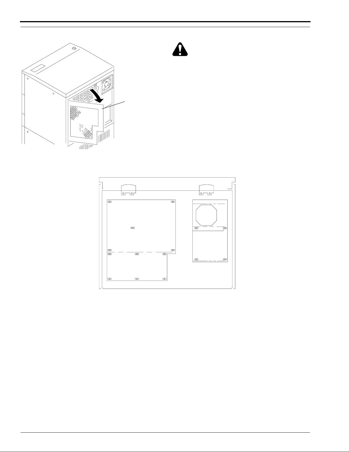
Front Control Unit Cover
BACK
CONTRO
UNIT
COVER
H129_0800ACB
H129_0800AC
LATCH (2)
Warning
Dangerous Voltage.
[1] De-energize the LASER PRINTER.
[2] Rotate each of the 2 SCREWS 30°.
[3] Disengage the FRONT CONTROL UNIT
COVER from the LATCHES.
[4] Lift up and remove the FRONT CONTROL
UNIT COVER.
FRONT CONTROL
UNIT COVER
2–2 29AUG97 – SM3226-1
SCREW (2)
H129_0600ACA
H129_0600AC
Right and Back Image Unit Covers
Removals
SCREW (2)
RIGHT
IMAGE
UNIT
COVER
SCREW (2)
BACK
IMAGE
UNIT
COVER
H129_0800ACC
H129_0800AC
Warning
Dangerous Voltage.
[1] De-energize the LASER PRINTER.
[2] Loosen the 2 SCREWS for the COVER being
removed by rotating each SCREW 90°
counterclockwise.
[3] Lift the bottom of the COVER to disengage it
from the LASER PRINTER.
[4] Remove the COVER.
Left Image Unit Cover
SCREW (2)
BLIND
COVER
SCREW (2)
P/J750
LEFT
IMAGE
UNIT
COVER
H129_0701ACB
H129_0701AC
Warning
Dangerous Voltage. Possible damage to eyes from
invisible laser beam.
[1] De-energize the LASER PRINTER.
[2] Remove the 4 BLIND COVER SCREWS.
[3] Disconnect the CONNECTOR J750.
[4] Loosen the 2 SCREWS for the LEFT IMAGE
UNIT COVER by rotating each SCREW 90°
counterclockwise.
Caution
Do not remove the LEFT IMAGE UNIT COVER until
J750 has been disconnected.
[5] Lift the bottom of the COVER to disengage it
from the LASER PRINTER.
[6] Remove the COVER.
SM3226-1 – 29AUG97 2–3

SERVICE MANUAL
E
E
E
Sequence Board Shield
SEQUENC
BOARD
SHIELD
H129_0601ACA
H129_0601AC
Warning
Dangerous Voltage.
[1] De-energize the LASER PRINTER.
[2] Remove the BACK IMAGE UNIT COVER.
[3] Open the SEQUENCE BOARD SHIELD.
Supply Magazine Door, Receive Magazine Door and User Access Door
RECEIVE
MAGAZIN
DOOR
USER
ACCESS
DOOR
SUPPLY
MAGAZIN
DOOR
H129_0701ACC
H129_0701AC
2–4 29AUG97 – SM3226-1

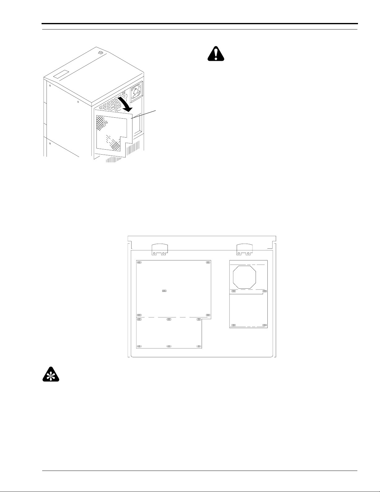
Top Cover
E
)
Removals
TOP
COVER
USER
ACCESS
DOOR
RECEIVE
MAGAZIN
DOOR
H129_0701ACD
H129_0701AC
[1] Open the RECEIVE MAGAZINE DOOR and the
USER ACCESS DOOR.
Warning
Dangerous Voltage. Possible damage to eyes from
invisible laser beam.
(a) Energize the LASER PRINTER.
(b) Wait about 1 minute for the PRINTER to
complete a system self-check.
Note
If no magazines are present, proceed to Step (e).
(c) Press the MAGAZINE DOOR OPEN/
CLOSE SWITCH.
(d) Wait until the LATCH SOLENOID
releases.
(e) Open the RECEIVE MAGAZINE DOOR.
(f) Press down the USER ACCESS DOOR
LATCH to open the USER ACCESS
DOOR.
[2] De-energize the LASER PRINTER.
[3] Remove the BACK IMAGE UNIT COVER. If
necessary, use the procedure on Page 2–3.
J230
J510
SCREW (4
H129_0602ACA
H129_0602AC
[4] Remove the 2 SCREWS from the front of the TOP
COVER and the 2 SCREWS from the back of the
TOP COVER.
[5] Disconnect J510 and J230.
[6] Lift and remove the COVER.
SM3226-1 – 29AUG97 2–5

SERVICE MANUAL
Right Inside Cover
SCREW (14)
RIGHT
INSIDE
COVER
H129_0603ACA
H129_0603AC
[1] Remove the RIGHT CONTROL UNIT COVER.
If necessary, see the procedure on Page 2–2.
[2] Loosen the 14 SCREWS.
[3] Lift and remove the RIGHT INSIDE COVER.
Left Inside Cover
LEFT
INSIDE
COVER
SCREW (14)
H129_0604ACA
H129_0604AC
[1] Remove the LEFT CONTROL UNIT COVER. If
necessary, see the procedure on Page 2–2.
[2] Loosen the 14 SCREWS.
[3] Lift and remove the LEFT INSIDE COVER.
2–6 29AUG97 – SM3226-1

Removals
Circuit Boards
Memory Board/6MB or 20MB
Warning
Dangerous Voltage.
Note
This board is called the Memory Management Board in the Wiring Diagrams.
[1] De-energize the LASER PRINTER.
[2] Remove the FRONT CONTROL UNIT COVER. If necessary, see the procedure on Page 2–2.
Caution
Possible damage from electrostatic discharge.
[3] Loosen the 2 SCREWS of the Kodak Ektascan 1120 MEMORY BOARD/6MB or 20MB located in SLOT 2.
[4] Remove the MEMORY BOARD/6MB or 20MB by sliding it forward.
MEMORY BOARD/6MB or
MEMORY BOARD/20MB
CARD
RACK
H129_1701BCA
H129_1701BC
SM3226-1 – 29AUG97 2–7

SERVICE MANUAL
C
BOARD
System Controller Board
Warning
Dangerous Voltage.
[1] De-energize the LASER PRINTER.
[2] Remove the FRONT CONTROL UNIT COVER.
If necessary, see the procedure on Page 2–2.
Caution
Possible damage from electrostatic discharge.
[3] Disconnect the CONNECTOR from the
SYSTEM CONTROLLER BOARD.
ONNECTOR
SCREW (2)
SYSTEM
CONTROLLER
CARD
RACK
H129_1700ACC
H129_1700AC
Note
A white dot is silk-screened on the circuit board next to pin position 1 for each jumper.
[4] Loosen the 2 SCREWS.
[5] Remove the SYSTEM CONTROLLER BOARD.
JUMPERS
[6] Check that the following Jumpers have been be installed:
J1-1 to J1-2
J2-1 to J2-2
J3-3 to J3-4
J4-3 to J4-4
J5-1 to J5-2, J5-4 to J5-5, J5-7 to J5-8, J5-10 to J5-11
J8-2 to J8-3
J9-1 to J9-2
J11-1 to J11-2
J12-1 to J12-2
J14-3 to J14-4
J15-1 to J15-2, J15-3 to J15-4
J16-1 to J16-2, J16-3 to J16-4, J16-5 to J16-6
J17-1 to J17-2
J18-1 to J18-3, J18-4 to J18-6, J18-5 to J18-7
J19-3 to J19-5, J19-4 to J19-6
J21-1 to J21-2
2–8 29AUG97 – SM3226-1
Install EPROMS
Caution
Possible damage from electrostatic discharge. Use correct procedures and equipment to prevent damage.
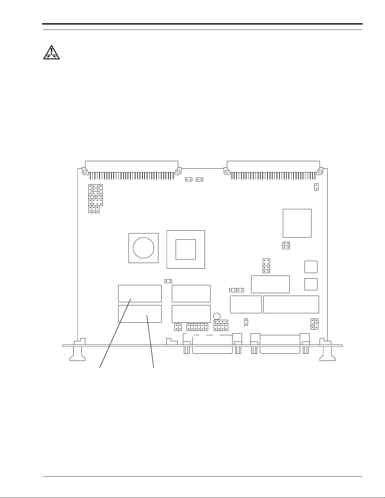
[1] Move the 2 EPROMS from the existing SYSTEM CONTROLLER BOARD to the new SYSTEM
CONTROLLER BOARD.
SYSTEM CONTROLLER BOARD
J22
J19
J18
J17
J16
J21
J20
Removals
EPROM
SYS EVEN
U22
J12
EPROM
SYS ODD
U1
J15
J14
J11
J10
J1
J2
J3
J4
J5
J6
J8
J9
H129_1712DCE
H129_1712DC
SM3226-1 – 29AUG97 2–9

SERVICE MANUAL
Print Controller Board
Warning
Dangerous Voltage.
[1] De-energize the LASER PRINTER.
[2] Remove the FRONT CONTROL UNIT COVER. If necessary, see the procedure on Page 2–2.
Caution
Possible damage from electrostatic discharge.
[3] Disconnect the CONNECTOR from the PRINT CONTROLLER BOARD, located in SLOT 3 of the CARD
RACK.
[4] Remove the 2 SCREWS.
[5] Remove the PRINT CONTROLLER BOARD by sliding it forward.
PRINT
CONTROLLER
BOARD
CARD
RACK
H129_1702BCA
H129_1702BC
2–10 29AUG97 – SM3226-1
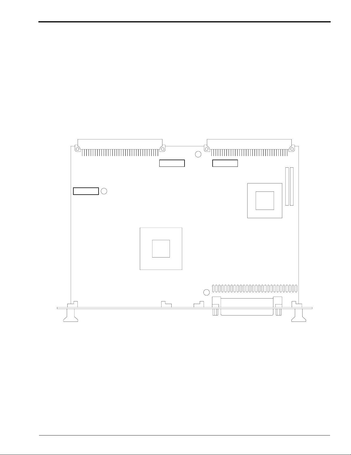
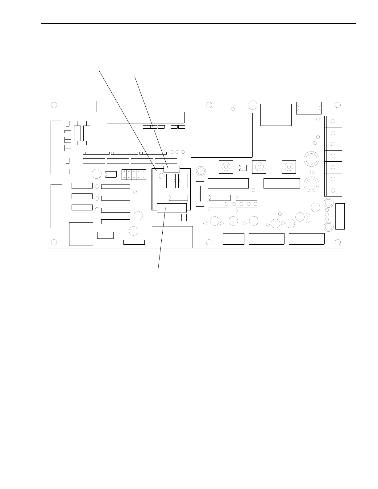
SWITCHES
[6] When installing a new PRINT CONTROLLER BOARD, check the following SWITCHES:
S1: Positions 1, 2, 3, 4, 6, and 8 are ON.
S2: Position 2 is ON.
S3: Position 7 is ON.
PRINT CONTROLLER BOARD
Removals
S1
S3
S2
H129_1713DC
SM3226-1 – 29AUG97 2–11
SERVICE MANUAL
E
Driver Board
SEQUENC
BOARD
SHIELD
H129_0601ACA
H129_0601AC
Warning
Dangerous Voltage.
[1] De-energize the LASER PRINTER.
[2] Remove the BACK IMAGE UNIT COVER. If
necessary, see the procedure on Page 2–3.
[3] Open the SEQUENCE BOARD SHIELD.
SEQUENCE BOARD
DRIVER BOARD (DRV)
FAN
(FAN)
SLOW SCAN
DRIVE (SSD)
H129_0802BC
2–12 29AUG97 – SM3226-1

Removals
29
30
39
40
1
2
1
2
H129_1706DC
1
2
22
21
1
2
23
24
H129_1706DCH
JP3
JP2
JP1
DSW1
RSW3
RSW2
RSW1
JUMPERS
[4] When installing a new DRIVER BOARD, check that the following JUMPERS are installed in the normal
position:
JP1
JP2
JP3
SWITCHES
[5] When installing a new DRIVER BOARD, check the following SWITCHES:
DSW1: Position 1 is ON
RSW1: Position 8 is ON
RSW2: Position 8 is ON
RSW3: Position 8 is ON
DRIVER BOARD
SM3226-1 – 29AUG97 2–13

SERVICE MANUAL
The Replacement of a Driver Board with a Universal Driver Board
When there is a need for a replacement for the DRIVER BOARD, install a UNIVERSAL DRIVER BOARD 696120.
Use the following table and figures to check for the correct JUMPER positions on the UNIVERSAL DRIVER
BOARD.
Note
If the DAUGHTER BOARD is removed from the UNIVERSAL DRIVER BOARD, return the DAUGHTER
BOARD to Part Services.
Printer Serial Number Daughter Board Jumper Pin P302 Connection
500025 - 500248 Used No Jumper
500259 - 500480
600001 - 600003
500481 and Up
600004 and Up
Not Used 1 to 2
3 to 4
5 to 6
Not Used No Jumper
2–14 29AUG97 – SM3226-1
UNIVERSAL DRIVER BOARD with DAUGHTER BOARD
DAUGHTER
BOARD
P301
Removals
2
34
30
1
33
2
1
29
1
2
18
A40
17
B40
10
1
1
1
6
5
1
10
A1
B1
5
10
2
2
1
2
11
12
1
22
1
21
24
23
P302
H129_1726DCC
H129_1726DC
SM3226-1 – 29AUG97 2–15

SERVICE MANUAL
UNIVERSAL DRIVER BOARD without DAUGHTER BOARD
P301
2
1
34
33
21
29
30
1
2
18
A40
17
B40
10
15
1
6
15
1
10
A1
B1
10
1
2
11
2
1
12
2
22
21
1
24
23
P302
H129_1725DCA
H129_1725DC
2–16 29AUG97 – SM3226-1

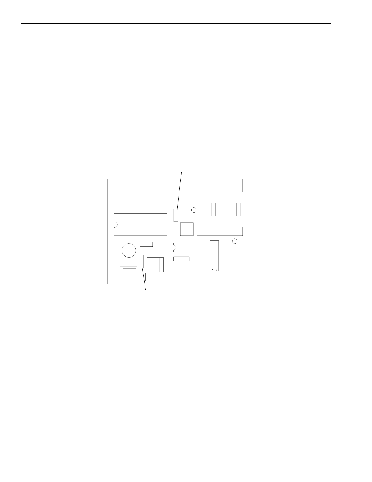
2-Phase Pulse Motor Driver Boards (2PMD)
Installation Notes
The LASER PRINTER has 2, 2-PHASE PULSE MOTOR DRIVER BOARDS (2PMD):
• the BEAM SPLITTER BOARD (2PMD-B)
• the SLIDE BASE MOTOR BOARD (2PMD-F)
• When replacing the BEAM SPLITTER BOARD, remove the HEAT SINK.
• When replacing the SLIDE BASE MOTOR BOARD, do not remove the HEAT SINK.
Install JUMPERS
[1] Check that the following JUMPERS are installed:
(a) BEAM SPLITTER BOARD
1. J1-1 to J1-2
2. J2-1 to J2-2
(b) SLIDE BASE MOTOR BOARD
1. J1-2 to J1-3
2. J2-1 to J2-2
Removals
2-PHASE PULSE MOTOR DRIVER BOARD (2PMD)
J2
J1
HEAT SINK
H129_1704BCB
H129_1704BC
SM3226-1 – 29AUG97 2–17
SERVICE MANUAL
J2
J1
5-Phase Pulse Motor Driver Boards (5PMD)
The LASER PRINTER has 3, 5-PHASE PULSE MOTOR DRIVER BOARDS (5PMD):
• the TRANSPORT ROLLER MOTOR BOARD (5PMD-T)
• the RECEIVE ROLLER MOTOR BOARD (5PMD-R)
• the SUPPLY ROLLER MOTOR BOARD (5PMD-S)
Install JUMPERS
[1] Check that the following JUMPERS are installed for each of the boards being installed:
1. J1-2 to J1-3
2. J2-2 to J2-3
[2] When installing a new board, do the adjustment procedure on Page 5–52.
5-PHASE PULSE MOTOR DRIVER BOARD (5PMD)
H129_1703BCB
H129_1703BC
2–18 29AUG97 – SM3226-1
Sequence Board
E
SEQUENC
BOARD
SHIELD
H129_0601ACA
H129_0601AC
Removals
Warning
Dangerous Voltage.
[1] De-energize the LASER PRINTER.
[2] Remove the BACK IMAGE UNIT COVER. If
necessary, see the procedure on Page 2–3
[3] Open the SEQUENCE BOARD SHIELD.
FAN
SEQUENCE BOARD
DRIVER BOARD (DRV)
(FAN)
SLOW SCAN
DRIVE (SSD)
Important
JUMPER information is subject to change with software updates and hardware changes.
H129_0802BC
SM3226-1 – 29AUG97 2–19

SERVICE MANUAL
3
4
5
JUMPERS
[4] Check JUMPER locations listed below with the board being replaced to ensure that no changes have been made.
[5] When installing a new SEQUENCE BOARD, check that the following JUMPERS are installed:
SJ1-1 to SJ1-2
SJ2-1 to SJ2-2
SJ3-1 to SJ3-2
SJ4-2 to SJ4-3
SJ5-2 to SJ5-3
*
SJ6-1 to SJ6-9, SJ6-2 to SJ6-10, SJ6-3 to SJ6-11, SJ6-4 to SJ6-12, SJ6-5 to SJ6-13, SJ6-6
to SJ6-14,
SJ6-8 to SJ6-16
SJ7-1 to SJ7-2.
*
For printers with serial number 500369 and above, SJ6-6 is open, along with the NEW GUIDE PLATE.
SEQUENCE BOARD
SJ6
SJ7
SJ1
SJ2
EPROM
ODD
EPROM
EVEN
SJ
SJ
SJ
H129_1705DCB
H129_1705DC
2–20 29AUG97 – SM3226-1
 Loading...