

Page 1
{InstallationInstructs} {P ro duction}{Health Group}{Int ern al}
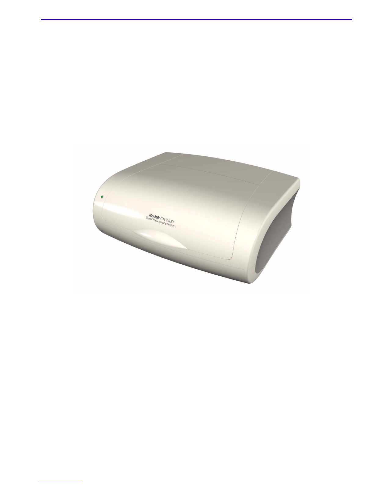
KODAK CR 7400 Digital
Radiography System
Installation Guide
Page 2

INSTALLATION INSTRUCTIONS
Carestream Health, Inc.
Dental Business
150 Verona St.
Rochester, NY 14608
Exclusive manufacturer of Kodak dental systems.
© Carestream Health, Inc., 2007
The Kodak trademark and trade dress are used under license from Kodak
6H4130_en
2 September 2007 – 6H4130
Page 3

KODAK CR 7400 Digital Radiography System Installation Manual
Document Part Number: 6H4130-00
Copyright Carestream Health, Inc., 2007
All rights reserved. No part of this manual may be reproduced or copied in any form by any means — graphic,
electronic or mechanical, including photocopying, typing, or information retrieval systems — without written
permission of Carestream Health, Inc.
Use of Manual
The Kodak CR 7400 digital radiography system is designed to meet international safety and performance standards.
Personnel operating the unit must have a thorough understanding of the proper operation of the system. This manual
has been prepared to aid medical and technical personnel to understand and operate the system. Do not operate the
system before reading this manual and gaining a clear understanding of the operation of the system. If any part of
this manual is not clear, please contact a representative for clarification.
US and Canada: Toll-free: 1-800-944-6365
www.kodakdental.com
6H4130 – September 2007 3
Page 4

INSTALLATION INSTRUCTIONS
Table of Contents
Description Page
Safety. . . . . . . . . . . . . . . . . . . . . . . . . . . . . . . . . . . . . . . . . . . . . . . . . . . . . . . . . . . . . . . . .5
Laser Safety Instructions
CR7400 System Requirements
Installing the User Interface Software of the KODAK CR 7400 system
Installing Microsoft.NET
Installing the Kodak CR 7400 driver for the WINDOWS Vista Operating System
Installing the Kodak CR 7400 driver for WINDOWS 2000 and WINDOW XP Operating
Systems . . . . . . . . . . . . . . . . . . . . . . . . . . . . . . . . . . . . . . . . . . . . . . . . . . . . . . . . . 13
KODAK CR 7400 System Setup
Initial setup
Selecting and Naming Rooms
Selecting Intraoral and Extraoral Preferences
Fine Tuning the CR7400
Items Required
. . . . . . . . . . . . . . . . . . . . . . . . . . . . . . . . . . . . . . . . . . . . . . . . . . . . . . . . . 17
. . . . . . . . . . . . . . . . . . . . . . . . . . . . . . . . . . . . . . . . . . . . . . 5
. . . . . . . . . . . . . . . . . . . . . . . . . . . . . . . . . . . . . . . . . . . . . 7
. . . . . . . . . . . . . . . 9
. . . . . . . . . . . . . . . . . . . . . . . . . . . . . . . . . . . . . . . . . . . . . . . 10
. . . . . . . . . . . . . . . . . . . . . . . . . . . . . . . . . . . . . . . . . . . . 17
. . . . . . . . . . . . . . . . . . . . . . . . . . . . . . . . . . . . . . . . . . 19
. . . . . . . . . . . . . . . . . . . . . . . . . . . . . . 20
. . . . . . . . . . . . . . . . . . . . . . . . . . . . . . . . . . . . . . . . . . . . . . 21
. . . . . . . . . . . . . . . . . . . . . . . . . . . . . . . . . . . . . . . . . . . . . . . . . . 21
. . . 12
Unit Setup
Intraoral Gain Verification
Extraoral Gain Verification
Gain Tuning Procedure
Appendix A: Tuning Process Results Form
. . . . . . . . . . . . . . . . . . . . . . . . . . . . . . . . . . . . . . . . . . . . . . . . . . . . . . 21
. . . . . . . . . . . . . . . . . . . . . . . . . . . . . . . . . . . . . . . . . . 22
. . . . . . . . . . . . . . . . . . . . . . . . . . . . . . . . . . . . . . . . . 23
. . . . . . . . . . . . . . . . . . . . . . . . . . . . . . . . . . . . . . . . . . . 25
. . . . . . . . . . . . . . . . . . . . . . . . . . . . . . . . . . . . 27
4 September 2007 – 6H4130
Page 5

Section 1: Safety
Caution
LIFTING HAZARD
• The Kodak CR 7400 unit weighs 18Kg (39.6lbs).
• Lifting heavy equipment may result in serious injury to personnel and/or damage to equipment. Do not try to lift
the unit by yourself.
CautionCaution
The Kodak CR 7400 digital radiography unit is a CLASS 1 Laser product.
• Do not remove the unit cover.
• Cover removal should be done only by authorized service personnel.
Laser Safety Instructions
During normal operation, the unit should always be enclosed in its protective cover to pr event the su rr oundin g a rea
from being exposed to the laser.
Cover removal should be performed for service purposes only and by an authorized technician.
6H4130 – September 2007 5
Page 6

INSTALLATION INSTRUCTIONS
6 September 2007 – 6H4130
Page 7

Section 2: CR7400 System Requirements
The system requirements for the CR7400 System is as follows:
• Intel pentium IV 3.2 GHZ or faster
•I GB RAM
• 80 GB hard drive
• CD-ROM drive
• Ethernet 10/100/1000 Network Card
• Standard CRT/LCD monitor with a minimum 1024 x 768 screen resolution
• 64MB graphic adapter (no graphics on board)
You can install the CR700 system on the following operating systems:
• Windows 2000 Professional SP4
• Windows XP Professional SP2
• Windows Vista Business 32-bit
Before installing the software, please review the system requirements at http://www.kodakdental.com/
documentation/sysReqs/KDSIS.pdf.
Important
Plug the CR7400 unit into a USB connector on the back of the PC. If you experience a data-transfer problem, install
an additional PCI-USB2 card. We recommend the D-Link DUB-2 card. When installing the card, leave at least 2 PCIslots empty between the PCI card and any graphic card you have installed. If using a laptop and experience
problems, install a PCMCIA-USB2 card. We recommend the Belkin USB 2.0 Notebook card.
6H4130 – September 2007 7
Page 8

INSTALLATION INSTRUCTIONS
8 September 2007 – 6H4130
Page 9
Section 3: Installing the User Interface Sof tware of the KODAK CR
7400 system
Important
Before installing the software, please review the system requirements at http://www.kodakdental.com/
documentation/sysReqs/KDSIS.pdf.
CautionCaution
Do not connect the CR7400 USB cable to your computer while installing the software.
After installing the Kodak dental imaging software (version 6.6.3 and up), proceed to the steps below.
• Microsoft.NET installation. This may already be installed on the computer, in which case it is automatically
skipped.
• User interface installation
• WIBU-Key installation (Microsoft Windows 2000 and XP operating system users skip this step)
• Continuation of installation
[1] Insert the user interface software CD for the Kodak CR 7400 system into the computer disk drive.
The installation begins automatically.
Note
If the installation does not begin automatically:
• Click My Computer.
• Click CD RW drive.
• Double-click the autorun.exe file.
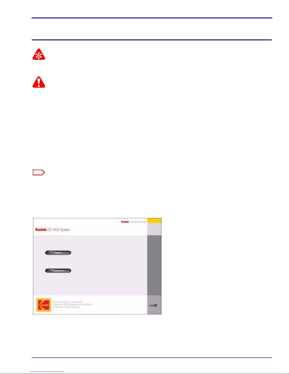
When the installation begins, the Kodak CR7 400 System Installation screen appears:
Starting Installation
6H4130 – September 2007 9
Page 10

INSTALLATION INSTRUCTIONS
Installing Microsoft.NET
[1] Click Install.
Allow the setup screens to start the procedure automatically.
• If Microsoft.NET has already been installed on the computer, the setup automatically skips ahead.
• If Microsoft.NET has not yet been installed, a Setup window is displayed, then the Microsoft.NET license
agreement appears.
[2] Click I agree, then click Install.The Installing Compo nen ts screen appears. When the installation is complete,
a Setup message is displayed.
[3] Click OK.
The installation continues and the following screens appear:
User interface installation continuing
[4] The InstallShield Wizard opens. Do one of the following:
• If you are installing the software on the Windows Vista operating system, the WIBU-KEY installation begins
and the WIBU-KEY Setup welcome screen appears. Complete steps 5
• If you are installing the software on the Windows 2000 through Windows XP operating systems, skip to step
12
.
[5] Click Next to continue. The WIBU-KEY tools are installed. A setup message appears.
[6] Click Yes to create a folder.
[7] Click Next to continue. A list of components to be installed appears.
[8] Click Next to install the components. A list of component to be installed appear s.
[9] Click Next to install the components. The WIBU-KEY Setup Complete screen appears.
[10] Uncheck Yes, I want to view the Readme text now, then click Finish. A successful installation message
appears.
[11] Click OK to complete the WIBU-KEY installation.
[12] Click Next. The Kodak CR7400 Install Shield Wizard appears.
[13] Click Continue. The Destination Folder screen appears.
10 September 2007 – 6H4130
through 10.
Page 11

[14] To install the software and images in the C:\Program files\Kodak\KodakQC folder, click Next; to change the
location of the program file or image folder click Change and enter the new destination.
Note
It is recommended that you install the software and images in the C:\Program files\Kodak\KodakQC folder.
The Ready to Install the Program screen appears:
Ready to Install the Program screen
[15] Click Install to begin installation. The software is installed.
[16] When the process is complete, click Finish to complete the installation.
The following screen confirms the installation of the user interface for Windows 2000 and Window XP users:
KODAK QC screen showing successful installation
The first part of the installation is completed.
[17] Continue to the next section, “Installing the Kodak CR 7400 Driver.”
6H4130 – September 2007 11
Page 12

INSTALLATION INSTRUCTIONS
Installing the Kodak CR 7400 driver for the WINDOWS Vista Operating
System
After you install the software, keep the user interface software CD-ROM in the computer disk drive and install the
Kodak CR 7400 driver as described below:
[1] Connect the power cable to the back of the Kodak CR 7400 unit.
USB connection
Fuse for erase lamps
On/off switch
Power cable connection and main fuse
Back view of unit
[2] Connect the power cable to the main outlet.
[3] Power on the unit by turning the on/off switch to “on.”
[4] Connect the USB2 cable from the unit to the computer. The Update Drive Software - Unknown Device screen
appears.
[5] Select Browse my computer for drive software. The Found New Hardware - Unknown Device screen
appears.
[6] Select Browse my computer for driver software (advanced). Indicate where to search for the software,
usually E:\Driver (where E: is the CD drive), and click Next. The driver software is installed.
[7] When the installation is complete, click Close. This completes the software installation for the Kodak CR 7400
unit. Proceed to the KODAK CR 7400 System Setup.
12 September 2007 – 6H4130
Page 13

Installing the Kodak CR 7400 driver for WINDOWS 2000 and WINDOW XP
Operating Systems
After you install the software, keep the user interface software CD-ROM in the computer disk drive and install the
Kodak CR 7400 driver as described below:
[1] Connect the power cable to the back of the Kodak CR 7400 unit.
USB connection
Fuse for erase lamps
On/off switch
Power cable connection and main fuse
Back view of unit
[2] Connect the power cable to the main outlet.
[3] Power on the unit by turning the on/off switch to “on.”
[4] Connect the USB2 cable from the unit to the computer. The Found New Hardware Wizard appears.
Found New Hardware Wizard
[5] Select No, not this time and click Next. The following screen appears:
6H4130 – September 2007 13
Page 14

INSTALLATION INSTRUCTIONS
New Hardware Wizard software search screen
[6] Select Install from a list or specific location and click Next. The following screen appears:
Software search location screen
[7] Indicate where to search for the software, usually E:\Driver\ (where E: is the CD drive), and click Next. When
the hardware is found, the following screen appears:
14 September 2007 – 6H4130
Page 15

Windows Logo warning
[8] Click Continue Anyway. An installation complete screen appears.
[9] Click Finish. This completes the software installation for the Kodak CR 7400 unit. Proceed to the KODAK CR
7400 System Setup.
6H4130 – September 2007 15
Page 16

INSTALLATION INSTRUCTIONS
16 September 2007 – 6H4130
Page 17

Section 4: KODAK CR 7400 System Setup
During all phases of Kodak CR 7400 system setup, the unit must be turned on and the USB cable connected between
the unit and the computer.
Initial setup
[1] Click on the Kodak Dental Software icon on the computer desktop.
[2] Select a patient and click “imaging” to access the imaging window.
[3] Click the CR icon.
The user interface screen appears:
Info/setup
button
User interface screen
To start scanning, choose and set your preferences as follows:
[4] Click the Info/Setup button.
[5] Select Technician Settings. The login screen appears:
[6] Enter the password “1331” in the password field, and click Login.
6H4130 – September 2007 17
Page 18

INSTALLATION INSTRUCTIONS
The Technician (level 1) screen appears with the Anatomical tab open:
Anatomical tab
18 September 2007 – 6H4130
Page 19

Selecting and Naming Rooms
In the Room Configuration area, select which rooms (up to four rooms) you want to make available on the Main
Screen. You may also change the names of the rooms.
[1]
[2]
Room Configuration area of Anatomical tab
[1] Select a room, then type over the existing name to change to the room name that you want.
[2] Choose whether to show or hide the room on the Main Screen.
[3] Click Apply to save your settings and continue to another tab.
[4] When you are finished making changes, click OK to save the settings and return to the Main Screen.
The Main Screen appears with your selections applied. The names and their show/hide preferences may be
changed at any time.
Main Screen with selections applied
Room name you assigned
Active room
Room 4 hidden because
“hide” was selected
6H4130 – September 2007 19
Page 20

INSTALLATION INSTRUCTIONS
Selecting Intraoral and Extraoral Preferences
[1] On the Main screen, click the Info/Setup button and log in as before.
[2] Select the Setup tab.
The Setup tab appears:
Plate configuration area
Setup tab
[3] In the Plate Configuration area of the Setup tab, select the pla tes you want to make ava ilable to each r oom.
Only the plates you select will appear on the Main Screen. Each room may have either intraoral or extraoral
plates, or both. You may change the settings at any time.
Select a room
Select an examination procedure
Selecting plate configuration
[4] Select a room from the Configuration Set drop-down menu.
[5] Select Intraoral or Extraoral from the Image type drop-down menu.
A list of available holders appears in the holders field on the left side:
20 September 2007 – 6H4130
Page 21

Available holders
Selecting plate configuration (continued)
[6] Select a holder, then click Add.
The holder moves from the list of available holders on the left to the list of selected holders on the right.
[7] Click Apply on the bottom of the Setup tab to save and apply your selection.
[8] Perform steps 3–6 to configure intraoral, extraoral, or both image types as you wish them to be associated with
the particular room.
[9] Click OK to return to the Main Screen.
Fine Tuning the CR7400
All Kodak CR 7400 systems pass calibration and tuning procedures before leaving the factory. Perform the following
procedures in the clinic after installation to verify unit calibration.
Items Required
• System: Kodak dental imaging software, version 6.6 or later, and Kodak CR7400 digital radiography system
user interface software, version 2.1 or later.
• Extraoral cassette with Kodak plate
• Intraoral holder for size 0-2 plate
• Intraoral plate size #2
• Intraoral tuning tool: square AL plate, 6-mm thick; part number SK-14009, SPBD681, SKU-CR140097, or
CAT #1817469
• Panoramic tuning tool: square AL plate, 15-mm thick; part number SK-0 00005, SKU00 0005, or SPCX05 0.
Unit Setup
[1] In the Acquisition window, click .
[2] Select Technician Settings, type 1331, and click Login.
[3] Click the Setup tab, and in the Diagnostic section check Load image viewer after scan.
[4] Click Apply, and click OK.
Note
After you tune the unit, repeat these steps and uncheck Load image viewer after scan.
6H4130 – September 2007 21
Page 22

INSTALLATION INSTRUCTIONS
Intraoral Gain Verification
[1] In the Acquisition window, set the button to Intraoral.
[2] Select High Speed scanning mode and select holder size 0-2.
[3] Type the x-r ay setting used in your practice for adult p atient s. See “
Tune the CR7400 unit.” on Page 27 for the factory setting for tuning a unit in production.
[4] Place an intraoral size #2 plate behind the 6mm phantom, aligned to the field center.
Table 1: Factory X-ray Parameters Used to
Gain Tuning Exposure
[5] Make an x-ray exposure. Wait 2 minutes after exposing the plate.
[6] Load the intraoral plate to the holder on slot #3 and click Scan. As the scan is completed, the image viewer
appears.
[7] Verify that No-Correction is selected in the Data correction method field.
[8] Place the cursor in the center of the image and read the pixel value.
[9] Verify the pixel value reaches 2900+
100.
[10] If the pixel value is within specifications, click Exit.
Important
If the pixel value is outside the range of 2900+100, perform the “Gain Tuning Procedure” on Page 25.
[11] Uncheck Load image viewer after scan.
22 September 2007 – 6H4130
Page 23

Extraoral Gain Ve r ification
[1] In the Acquisition window, set the button to Extraoral.
[2] Select High Speed scanning mode.
[3] Type the x-ray setting used in your practice for adu lt patient s. See Table 1 for the factory setting for tuning a unit
in production.
[4] Load a freshly erased plate into the cassette.
[5] Do one of the following:
• If using cephalometric imaging mode, attach 6mm-thick AL phan tom on the center of the cassette and insert
it into the cassette slot on the ceph x-ray machine.
Note
Using masking tape to secure the phantom.
If using panoramic imaging mode, attache 15mm-thick AL phantom on the secondary collimator slot of
the panoramic x-ray machine and the panoramic cassette into the cassette slot as detailed in the
following diagram.
[6] Make an x-ray exposure, and wait 2 minutes after exposing the plate.
[7] Load the plate into the CR7400 drum and click Scan. As the scan is completed, the image is displayed in the
image diagnostic viewer.
[8] Verify that No-Correction is selected in the Data correction method field.
[9] Do one of the following:
• If using cephalometric imaging mode, measure the pixel value in the center of the image.
• If using panoramic mode, measure the pixel value at the end quarters.
6H4130 – September 2007 23
Page 24

INSTALLATION INSTRUCTIONS
Image Viewer Window
[10] Verify that the pixel value reaches 2900+
100.
[11] If the pixel value is within specifications, the procedure is complete.
• Exit the image viewer.
• Click the Setup tab and deselect Load image viewer after scan.
• Click OK.
Important
If the pixel value is outside the range of 2900+100, perform the “Gain Tuning Procedure” on Page 25.
24 September 2007 – 6H4130
Page 25

Gain Tuning Procedure
[1] If the pixel value needs adjustment, proceed as follows:
• To increase the pixel value, type a value in the Simulate PM Gain box lower than the value that appears
in the Scanned PM Gain box.
• To decrease the pixel value, type a value in the Simulate PM Gain box higher than the value that appears
in the Scanned PM Gain box.
[2] Click the Process button, and check the pixel value in the center of the image.
Enter new values here
Pixel Value
Gain setting section of Image Viewer screen
[3] Repeat steps 1 and 2 until the target pixel value is obtained.
[4] Record the simulated PM gain, and click Exit.
[5] Launch the CR Acquisition window setup and click the Anatomical tab on the Scanner setup screen.
[6] Type the recorded simulated PM gain from step 4 in the PM in the Room Configuration section of the screen,
and select the correct room.
[7] If the pixel value is correct, click Accept and Exit.
Important
If the pixel value is not correct perform either the “Intraoral Gain Verification” on Page 22 or “Extraoral Gain
Verification” on Page 23
[8] Uncheck Load image viewer after scan.
6H4130 – September 2007 25
Page 26

INSTALLATION INSTRUCTIONS
26 September 2007 – 6H4130
Page 27

Section 5: Appendix A: Tuning Process Results Form
Table 1: Factory X-ray Parameters Used to Tune the CR7400 unit.
IMAGING MODE X-RAY TUBE SID EXPOSURE TIME
Intraoral 70kV, 8mA 12” 0.16s
cephalometric 70kV, 10mA 150cm 0.17s
Panoramic 70kV, 8mA 45.5cm 12s
Tuning Process Results
Machine Serial Number:
Software version:
Date:
Tested by:
Signature:
X-ray Exposure Conditions:
Intraoral cephalometric Panoramic
Parameter
Units
Factory Actual Factory Actual Factory Actual
X-ray tube voltage
and current
Exposure time 0.16 0.75 12 sec.
FSFD 12 in. 150 cm 45.5 cm Data C3
Screen identification Data C4
Screen format 31 x 41 Ceph Pan mm x mm
70; 8 70; 10 70; 8 kVp; mA
6H4130 – September 2007 27
Page 28

INSTALLATION INSTRUCTIONS
Tuning Results
Pixel value
Intraoral cephalometric c
e
Extraoral
p
h
a
l
o
m
e
t
r
i
c
Required Measured Required Measured Required Measured
Required 2900±100 2900±100 2900±100
PM gain set at
>40 >40 >40
the end of tuning
process
28 September 2007 – 6H4130
 Loading...