

Page 1

{IllustratedPartsList}{ Production}{Carestream H ealth Inc.}{None}
Publication No. 6H4869
17MAR2010
Supersedes 6H4869-01
23DEC09
Service Manual
for the
KODAK Point-of-Care CR 360 System
Important
• Qualified service personnel must install this modification.
• See the Service Portal for possible updates before doing this modification.
• When doing the procedures in this document, yo u must use safe work practices and wear the correct personal
protective equipment (for example, safety eyewear) according to your company’s standard operating
procedures.
None
© CARESTREAM HEALTH, INC. 2010
Page 2

Service Guide
KODAK Point-of-Care CR 360 System Service Manual
Publication Number: 6H4869
© Carestream Health, Inc., 2010
US FEDERAL LAW RESTRICTS THIS DEVICE TO SALE BY OR ON THE ORDER OF A PHYSICIAN ONLY.
All rights reserved. No part of this manual may be repr oduced or copied in any form by any means–graphic, electronic
or mechanical, including photocopying, typing, or informati on retrieval systems–without written permission of
Carestream Health, Inc.
Use of Manual
The KODAK Point-of-Care CR 360 System is designed to meet international safety and performance standards.
Personnel operating the unit must have a thorough understanding of th e proper operation of the system. This manual
has been prepared to aid medical and t echnical personnel to understand and operate the system. Do not operat e the
system before reading this manual and gaining a clear understanding of the operation of the system. If any part of
this manual is not clear, please contact your Carestream Health representative for clarification.
Authorized European Representative
Carestream Health France
LES MERCURIALES
40, rue Jean Jaures
93176 BAGNOLET CEDEX
France
The Kodak trademark and trade dress are used under license f rom Kodak.
Carestream Health, Inc.
150 Verona Street
Rochester, NY 14608
2 6H4869
Page 3

Table of Contents
Description Page
Safety and Regulatory Information. . . . . . . . . . . . . . . . . . . . . . . . . . . . . . . . . . . . . . . . . . . 9
Introduction
General Safety Guidelines
Electrical Hazards
Explosion and Implosion Hazards
Overheating
Laser Safety Instructions
Recycling the Unit
Labelling Summary
IEC Symbols Used
Device-specific Safety Information
Regulatory Information
System Description
Introduction
Operational Principles
System Overview
Component Description
Service Procedures
Service Tools
Removing the Scanner Cover
Installing the Scanner Cover
Activating the Scanner Without the Cover
Replacing the Power Line Filter Module
Replacing the Fuses
Replacing the Controller Board
. . . . . . . . . . . . . . . . . . . . . . . . . . . . . . . . . . . . . . . . . . . . . . . . . . . . . . . . . 9
. . . . . . . . . . . . . . . . . . . . . . . . . . . . . . . . . . . . . . . . . . . . . 9
. . . . . . . . . . . . . . . . . . . . . . . . . . . . . . . . . . . . . . . . . . . . . . . . . . . . 10
. . . . . . . . . . . . . . . . . . . . . . . . . . . . . . . . . . . . . . . 10
. . . . . . . . . . . . . . . . . . . . . . . . . . . . . . . . . . . . . . . . . . . . . . . . . . . . . . . . 10
. . . . . . . . . . . . . . . . . . . . . . . . . . . . . . . . . . . . . . . . . . . . . . 10
. . . . . . . . . . . . . . . . . . . . . . . . . . . . . . . . . . . . . . . . . . . . . . . . . . . . 11
. . . . . . . . . . . . . . . . . . . . . . . . . . . . . . . . . . . . . . . . . . . . . . . . . . . 11
. . . . . . . . . . . . . . . . . . . . . . . . . . . . . . . . . . . . . . . . . . . . . . . . . . . 11
. . . . . . . . . . . . . . . . . . . . . . . . . . . . . . . . . . . . . . . 12
. . . . . . . . . . . . . . . . . . . . . . . . . . . . . . . . . . . . . . . . . . . . . . . . 12
Introduction
CE Conformity
USA Regulations
Component Names and Descriptions
Views of the Point-of-Care CR 360
Power Line Filter Module
IMCS Board
Linear Slide Assembly
Overview
Two Types of Linear Screws
Linear Motor
Optical Head Assembly
Photo Multiplier Assembly (PM)
Loader Stepper Assembly
Roller Drive Motor Assembly
Right and Left Limit Sensors
Activation Procedures
Activating the Scanner Without the Cover (Laser Deactivated)
Before Service Operations
After Service Operations
Activating the Scanner without the Cover (Laser Activated)
Before Service Operations
After Service Operations
Tools Required
Removing the Power Line Filter Module
Installing the Power Line Filter Module
Tools Required
Procedure
Tools Required
. . . . . . . . . . . . . . . . . . . . . . . . . . . . . . . . . . . . . . . . . . . . . . . . . . . . . 12
. . . . . . . . . . . . . . . . . . . . . . . . . . . . . . . . . . . . . . . . . . . . . . . . . . 12
. . . . . . . . . . . . . . . . . . . . . . . . . . . . . . . . . . . . . . . . . . . . . . . . 12
. . . . . . . . . . . . . . . . . . . . . . . . . . . . . . . . . . . . . . . . . . . . . . . . . . . . . . . 13
. . . . . . . . . . . . . . . . . . . . . . . . . . . . . . . . . . . . . . . . . . . . . . . . . . . . . . . . . 13
. . . . . . . . . . . . . . . . . . . . . . . . . . . . . . . . . . . . . . . . . . . . . . . . . 13
. . . . . . . . . . . . . . . . . . . . . . . . . . . . . . . . . . . . . . . . . . . . . . . . . . . . 14
. . . . . . . . . . . . . . . . . . . . . . . . . . . . . . . . . 14
. . . . . . . . . . . . . . . . . . . . . . . . . . . . . . . . . . . 16
. . . . . . . . . . . . . . . . . . . . . . . . . . . . . . . . . . . . . . . . . . . . . . . 18
. . . . . . . . . . . . . . . . . . . . . . . . . . . . . . . . . . . . . . . . . . 18
. . . . . . . . . . . . . . . . . . . . . . . . . . . . . . . . . . . . . . . . . . . . . . . . . . . . 18
. . . . . . . . . . . . . . . . . . . . . . . . . . . . . . . . . . . . . . . . . . . . 19
. . . . . . . . . . . . . . . . . . . . . . . . . . . . . . . . . . . . . . . . . . . . . . . . . . . 19
. . . . . . . . . . . . . . . . . . . . . . . . . . . . . . . . . . . . 19
. . . . . . . . . . . . . . . . . . . . . . . . . . . . . . . . . . . . . . . . . . . . . . . . . . . . 20
. . . . . . . . . . . . . . . . . . . . . . . . . . . . . . . . . . . . . . . . . . . 20
. . . . . . . . . . . . . . . . . . . . . . . . . . . . . . . . . . . . . 21
. . . . . . . . . . . . . . . . . . . . . . . . . . . . . . . . . . . . . . . . . 22
. . . . . . . . . . . . . . . . . . . . . . . . . . . . . . . . . . . . . . . 22
. . . . . . . . . . . . . . . . . . . . . . . . . . . . . . . . . . . . . . . . 23
. . . . . . . . . . . . . . . . . . . . . . . . . . . . . . . . . . . . . . . . . . . . . . . . . . . . . . 24
. . . . . . . . . . . . . . . . . . . . . . . . . . . . . . . . . . . . . . . . . . . . . . . . . . . . . . . 24
. . . . . . . . . . . . . . . . . . . . . . . . . . . . . . . . . . . . . . . . . . . 25
. . . . . . . . . . . . . . . . . . . . . . . . . . . . . . . . . . . . . . . . . . . . 25
. . . . . . . . . . . . . . . . . . . . . . . . . . . . . . . . . 26
. . . . . . . . . . . . . . . . . . . . . . . . . . . . . . . . . . . . . . . . . . . . . 26
. . . . . . . . . . . . . . . . . . . . . . . . . . . . . . . . . . . . . 26
. . . . . . . . . . . . . . . . . . . . . . . . . . . . . . . . . . . . . . . 27
. . . . . . . . . . . . . . . . 27
. . . . . . . . . . . . . . . . . . . . . . . . . . . . . . . . . . . . . 27
. . . . . . . . . . . . . . . . . . . . . . . . . . . . . . . . . . . . . . . 27
. . . . . . . . . . . . . . . . . . . . . . . . . . . . . . . . . . . 28
. . . . . . . . . . . . . . . . . . . . . . . . . . . . . . . . . . . . . . . . . . . . . . . . . . 28
. . . . . . . . . . . . . . . . . . . . . . . . . . . . . . . 28
. . . . . . . . . . . . . . . . . . . . . . . . . . . . . . . . 29
. . . . . . . . . . . . . . . . . . . . . . . . . . . . . . . . . . . . . . . . . . . . . . . . . . 30
. . . . . . . . . . . . . . . . . . . . . . . . . . . . . . . . . . . . . . . . . . . . . . . . . . 30
. . . . . . . . . . . . . . . . . . . . . . . . . . . . . . . . . . . . . . . . . . . . . . . . . . . . . . 30
. . . . . . . . . . . . . . . . . . . . . . . . . . . . . . . . . . . . . . . . . . 32
. . . . . . . . . . . . . . . . . . . . . . . . . . . . . . . . . . . . . . . . . . . . . . . . . . 32
. . . . . . . . . . . . . 26
6H4869 3
Page 4

Service Guide
Removing the Controller Board . . . . . . . . . . . . . . . . . . . . . . . . . . . . . . . . . . . . . 32
Installing the Controller Board
Replacing the IMCS Board
Tools Required
. . . . . . . . . . . . . . . . . . . . . . . . . . . . . . . . . . . . . . . . . . . . . 36
. . . . . . . . . . . . . . . . . . . . . . . . . . . . . . . . . . . . . . . . . . . . . . . . . . 36
Removing the IMCS Board
Separating the Sensor Board from the Motion Board
Installing the IMCS Board
Replacing the Photo Multiplier Board
Tools Required
. . . . . . . . . . . . . . . . . . . . . . . . . . . . . . . . . . . . . . . . . . . . . . . . . . 39
Removing the PM Board
Installing the PM Board
Replacing the Photo Multiplier Assembly
Tools Required
. . . . . . . . . . . . . . . . . . . . . . . . . . . . . . . . . . . . . . . . . . . . . . . . . . 41
Removing the PM Tube
Installing the PM Tube
. . . . . . . . . . . . . . . . . . . . . . . . . . . . . . . . . . . . . . . . . . . . 43
Replacing the Optical Head Assembly
Tools Required
. . . . . . . . . . . . . . . . . . . . . . . . . . . . . . . . . . . . . . . . . . . . . . . . . . 45
Removing the Optical Head Assembly
Installing the Optical Head Assembly
Replacing the Linear Screw Type A
Tools Required
. . . . . . . . . . . . . . . . . . . . . . . . . . . . . . . . . . . . . . . . . . . . . . . . . . 48
Removing the Linear Screw Type A
Installing the Linear Screw Type A
Replacing the Linear Screw Type B
Tools Required
. . . . . . . . . . . . . . . . . . . . . . . . . . . . . . . . . . . . . . . . . . . . . . . . . . 50
Removing the Linear Screw Type B
Installing the Linear Screw Type B
Test Procedure
. . . . . . . . . . . . . . . . . . . . . . . . . . . . . . . . . . . . . . . . . . . . . . . . . . 53
Replacing the Linear Motor Type A
Tools Required
. . . . . . . . . . . . . . . . . . . . . . . . . . . . . . . . . . . . . . . . . . . . . . . . . . 54
Removing the Linear Motor Type A
Installing the Linear Motor Type A
Replacing the Linear Motor Type B
Tools Required
. . . . . . . . . . . . . . . . . . . . . . . . . . . . . . . . . . . . . . . . . . . . . . . . . . 58
Removing Type B Linear Motor
Installing the Linear Motor Type B
Replacing the Roller Drive Motor Assembly
Tools Required
. . . . . . . . . . . . . . . . . . . . . . . . . . . . . . . . . . . . . . . . . . . . . . . . . . 64
Removing the Drive Roller Motor Assembly
Installing the Roller Drive Motor
Replacing the Loader Stepper Assembly
Tools Required
. . . . . . . . . . . . . . . . . . . . . . . . . . . . . . . . . . . . . . . . . . . . . . . . . . 67
Removing the Loader Stepper Assembly
Installing the Loader Stepper Assembly
Replacing the Laser Board
Tools Required
. . . . . . . . . . . . . . . . . . . . . . . . . . . . . . . . . . . . . . . . . . . . . 69
. . . . . . . . . . . . . . . . . . . . . . . . . . . . . . . . . . . . . . . . . . . . . . . . . . 69
Removing the Laser Board
Installing the Laser Board
Replacing the Power Supply
Tools Required
. . . . . . . . . . . . . . . . . . . . . . . . . . . . . . . . . . . . . . . . . . . . . . . . . . 71
Removing the Power Supply Unit
Installing the Power Supply Unit
Replacing the Erase Lamps Assembly
Tools Required
. . . . . . . . . . . . . . . . . . . . . . . . . . . . . . . . . . . . . . . . . . . . . . . . . . 77
Removing the Erase Lamps Assembly
Installing the Erase Lamps Assembly
Replacing the Erase Lamps Fuse
Tools Required
. . . . . . . . . . . . . . . . . . . . . . . . . . . . . . . . . . . . . . . . . . . . . . . . . . 80
Installing the Erase Lamps Fuse
. . . . . . . . . . . . . . . . . . . . . . . . . . . . . . . . . . . . . . 34
. . . . . . . . . . . . . . . . . . . . . . . . . . . . . . . . . . . . . . . . . 36
. . . . . . . . . . . . . . . . . . . . 37
. . . . . . . . . . . . . . . . . . . . . . . . . . . . . . . . . . . . . . . . . . 38
. . . . . . . . . . . . . . . . . . . . . . . . . . . . . . . . . . . . . 39
. . . . . . . . . . . . . . . . . . . . . . . . . . . . . . . . . . . . . . . . . . 39
. . . . . . . . . . . . . . . . . . . . . . . . . . . . . . . . . . . . . . . . . . . 40
. . . . . . . . . . . . . . . . . . . . . . . . . . . . . . . . . . 41
. . . . . . . . . . . . . . . . . . . . . . . . . . . . . . . . . . . . . . . . . . . 41
. . . . . . . . . . . . . . . . . . . . . . . . . . . . . . . . . . . . 45
. . . . . . . . . . . . . . . . . . . . . . . . . . . . . . . . 45
. . . . . . . . . . . . . . . . . . . . . . . . . . . . . . . . . 46
. . . . . . . . . . . . . . . . . . . . . . . . . . . . . . . . . . . . . . 48
. . . . . . . . . . . . . . . . . . . . . . . . . . . . . . . . . . 48
. . . . . . . . . . . . . . . . . . . . . . . . . . . . . . . . . . . 49
. . . . . . . . . . . . . . . . . . . . . . . . . . . . . . . . . . . . . . 50
. . . . . . . . . . . . . . . . . . . . . . . . . . . . . . . . . . 50
. . . . . . . . . . . . . . . . . . . . . . . . . . . . . . . . . . . 52
. . . . . . . . . . . . . . . . . . . . . . . . . . . . . . . . . . . . . . 54
. . . . . . . . . . . . . . . . . . . . . . . . . . . . . . . . . . 54
. . . . . . . . . . . . . . . . . . . . . . . . . . . . . . . . . . . 56
. . . . . . . . . . . . . . . . . . . . . . . . . . . . . . . . . . . . . . 58
. . . . . . . . . . . . . . . . . . . . . . . . . . . . . . . . . . . . . 58
. . . . . . . . . . . . . . . . . . . . . . . . . . . . . . . . . . . 61
. . . . . . . . . . . . . . . . . . . . . . . . . . . . . . . . 64
. . . . . . . . . . . . . . . . . . . . . . . . . . . . 64
. . . . . . . . . . . . . . . . . . . . . . . . . . . . . . . . . . . . . 65
. . . . . . . . . . . . . . . . . . . . . . . . . . . . . . . . . . 67
. . . . . . . . . . . . . . . . . . . . . . . . . . . . . . 67
. . . . . . . . . . . . . . . . . . . . . . . . . . . . . . . 67
. . . . . . . . . . . . . . . . . . . . . . . . . . . . . . . . . . . . . . . . . 69
. . . . . . . . . . . . . . . . . . . . . . . . . . . . . . . . . . . . . . . . . . 70
. . . . . . . . . . . . . . . . . . . . . . . . . . . . . . . . . . . . . . . . . . . 71
. . . . . . . . . . . . . . . . . . . . . . . . . . . . . . . . . . . . 71
. . . . . . . . . . . . . . . . . . . . . . . . . . . . . . . . . . . . . 75
. . . . . . . . . . . . . . . . . . . . . . . . . . . . . . . . . . . 77
. . . . . . . . . . . . . . . . . . . . . . . . . . . . . . . 77
. . . . . . . . . . . . . . . . . . . . . . . . . . . . . . . . 78
. . . . . . . . . . . . . . . . . . . . . . . . . . . . . . . . . . . . . . . 80
. . . . . . . . . . . . . . . . . . . . . . . . . . . . . . . . . . . . 80
4 6H4869
Page 5

Test Procedure. . . . . . . . . . . . . . . . . . . . . . . . . . . . . . . . . . . . . . . . . . . . . . . . . . 80
Replacing the Erase Lamp Board
Tools Required
. . . . . . . . . . . . . . . . . . . . . . . . . . . . . . . . . . . . . . . . . . . . . . . . . . 81
Removing the Erase Lamp Board
Installing the Erase Lamp Board
Replacing the Erase Lamps Inverter Board
Tools Required
. . . . . . . . . . . . . . . . . . . . . . . . . . . . . . . . . . . . . . . . . . . . . . . . . . 82
Removing the Erase Lamps Inverter Board
Installing the Erase Lamps Inverter Board
Replacing the Roof Assembly and Tray Assembly
Introduction
Tools Required
. . . . . . . . . . . . . . . . . . . . . . . . . . . . . . . . . . . . . . . . . . . . . . . . . . . . . 83
. . . . . . . . . . . . . . . . . . . . . . . . . . . . . . . . . . . . . . . . . . . . . . . . . . 83
Removing the Roof Assembly
Removing the Tray Assembly
Installing the Tray Assembly and the Roof Assembly
Test Procedure
. . . . . . . . . . . . . . . . . . . . . . . . . . . . . . . . . . . . . . . . . . . . . . . . . . 87
Replacing the Right and Left Limit Sensors
Tools Required
. . . . . . . . . . . . . . . . . . . . . . . . . . . . . . . . . . . . . . . . . . . . . . . . . . 88
Removing the Right Limit Sensor
Installing the Right Limit Sensor
Removing the Left Limit Sensor
Installing the Left Limit Sensor
Replacing the LED Indicator
Tools Required
. . . . . . . . . . . . . . . . . . . . . . . . . . . . . . . . . . . . . . . . . . . . . . . . . . 91
Removing the LED Indicator
Installing the LED Indicator
LED Indicator Test Procedure
Replacing the Cassette Status Sensors
Tools Required
. . . . . . . . . . . . . . . . . . . . . . . . . . . . . . . . . . . . . . . . . . . . . . . . . . 93
Removing the Cassette Status Sensors
Installing the Cassette Status Sensors
Cassette Status Sensors Test Procedure
Replacing the Cassette Fixation Lever Assembly
Tools Required
. . . . . . . . . . . . . . . . . . . . . . . . . . . . . . . . . . . . . . . . . . . . . . . . . . 95
Removing the Cassette Fixation Lever Assembly
Installing the Casette Fixation Lever Assembly
Replacing the W0 Sensor
Tools Required
. . . . . . . . . . . . . . . . . . . . . . . . . . . . . . . . . . . . . . . . . . . . . . 98
. . . . . . . . . . . . . . . . . . . . . . . . . . . . . . . . . . . . . . . . . . . . . . . . . . 98
Removing the W0 Sensor
Installing the W0 Sensor
W0 Sensor Test Procedure
Replacing the Z0 Sensor
Tools Required
. . . . . . . . . . . . . . . . . . . . . . . . . . . . . . . . . . . . . . . . . . . . . . 101
. . . . . . . . . . . . . . . . . . . . . . . . . . . . . . . . . . . . . . . . . . . . . . . . . . 101
Removing the Z0 Sensor
Installing the Z0 Sensor
Z0 Sensor Test Procedure
Installing the IGUS Energy Chain
Tools Required
Procedure
. . . . . . . . . . . . . . . . . . . . . . . . . . . . . . . . . . . . . . . . . . . . . . . . . . 103
. . . . . . . . . . . . . . . . . . . . . . . . . . . . . . . . . . . . . . . . . . . . . . . . . . . . . . 103
Testing and Closing the Scanner Cover
Replacing the Barcode Reader
Tools Required
. . . . . . . . . . . . . . . . . . . . . . . . . . . . . . . . . . . . . . . . . . . . . . . . . . 110
Removing the Barcode Reader
Installing the Barcode Reader
Calibrations
Introduction
Origin Calibration
6H4869 5
. . . . . . . . . . . . . . . . . . . . . . . . . . . . . . . . . . . . . . . . . . . . . . . . . . . . . . . . . . . . . 114
. . . . . . . . . . . . . . . . . . . . . . . . . . . . . . . . . . . . . . . . . . . . . . . . . . . . . . . . . 114
The Calibrations Tab
Equipment Required
. . . . . . . . . . . . . . . . . . . . . . . . . . . . . . . . . . . . . . . . . . . . . 114
. . . . . . . . . . . . . . . . . . . . . . . . . . . . . . . . . . . . . . . . . . . . . . 114
. . . . . . . . . . . . . . . . . . . . . . . . . . . . . . . . . . . . . . . . . . . . . . . . . . . . 115
. . . . . . . . . . . . . . . . . . . . . . . . . . . . . . . . . . . . . . . . 81
. . . . . . . . . . . . . . . . . . . . . . . . . . . . . . . . . . . . 81
. . . . . . . . . . . . . . . . . . . . . . . . . . . . . . . . . . . . . 81
. . . . . . . . . . . . . . . . . . . . . . . . . . . . . . . . 82
. . . . . . . . . . . . . . . . . . . . . . . . . . . . 82
. . . . . . . . . . . . . . . . . . . . . . . . . . . . . 82
. . . . . . . . . . . . . . . . . . . . . . . . . . . 83
. . . . . . . . . . . . . . . . . . . . . . . . . . . . . . . . . . . . . . 83
. . . . . . . . . . . . . . . . . . . . . . . . . . . . . . . . . . . . . . . 85
. . . . . . . . . . . . . . . . . . . . . 86
. . . . . . . . . . . . . . . . . . . . . . . . . . . . . . . . 88
. . . . . . . . . . . . . . . . . . . . . . . . . . . . . . . . . . . . 88
. . . . . . . . . . . . . . . . . . . . . . . . . . . . . . . . . . . . . 89
. . . . . . . . . . . . . . . . . . . . . . . . . . . . . . . . . . . . . 89
. . . . . . . . . . . . . . . . . . . . . . . . . . . . . . . . . . . . . . 90
. . . . . . . . . . . . . . . . . . . . . . . . . . . . . . . . . . . . . . . . . . . . 91
. . . . . . . . . . . . . . . . . . . . . . . . . . . . . . . . . . . . . . . . 91
. . . . . . . . . . . . . . . . . . . . . . . . . . . . . . . . . . . . . . . . . 91
. . . . . . . . . . . . . . . . . . . . . . . . . . . . . . . . . . . . . . 92
. . . . . . . . . . . . . . . . . . . . . . . . . . . . . . . . . . . 93
. . . . . . . . . . . . . . . . . . . . . . . . . . . . . . . 93
. . . . . . . . . . . . . . . . . . . . . . . . . . . . . . . . 93
. . . . . . . . . . . . . . . . . . . . . . . . . . . . . . 94
. . . . . . . . . . . . . . . . . . . . . . . . . . . 95
. . . . . . . . . . . . . . . . . . . . . . . 95
. . . . . . . . . . . . . . . . . . . . . . . . . 97
. . . . . . . . . . . . . . . . . . . . . . . . . . . . . . . . . . . . . . . . . . 98
. . . . . . . . . . . . . . . . . . . . . . . . . . . . . . . . . . . . . . . . . . . 99
. . . . . . . . . . . . . . . . . . . . . . . . . . . . . . . . . . . . . . . . 100
. . . . . . . . . . . . . . . . . . . . . . . . . . . . . . . . . . . . . . . . . . 101
. . . . . . . . . . . . . . . . . . . . . . . . . . . . . . . . . . . . . . . . . . . 101
. . . . . . . . . . . . . . . . . . . . . . . . . . . . . . . . . . . . . . . . . 102
. . . . . . . . . . . . . . . . . . . . . . . . . . . . . . . . . . . . . . . . 103
. . . . . . . . . . . . . . . . . . . . . . . . . . . . . . . 109
. . . . . . . . . . . . . . . . . . . . . . . . . . . . . . . . . . . . . . . . . . 110
. . . . . . . . . . . . . . . . . . . . . . . . . . . . . . . . . . . . . 110
. . . . . . . . . . . . . . . . . . . . . . . . . . . . . . . . . . . . . . 111
Page 6

Service Guide
Offset Calibration . . . . . . . . . . . . . . . . . . . . . . . . . . . . . . . . . . . . . . . . . . . . . . . . . . . . 116
System Gain Tuning
Purpose
. . . . . . . . . . . . . . . . . . . . . . . . . . . . . . . . . . . . . . . . . . . . . . . . . . . . . . . 117
System Gain Tuning Procedure
OCPC Process Calibration
Purpose
. . . . . . . . . . . . . . . . . . . . . . . . . . . . . . . . . . . . . . . . . . . . . . . . . . . . . . . 118
OCPC Process Calibration Procedure
Adjustments
. . . . . . . . . . . . . . . . . . . . . . . . . . . . . . . . . . . . . . . . . . . . . . . . . . . . . . . . . . . . 120
Adjusting the Cassette Release Mechanism
Tools Required
Adjustment Procedure
Auto-loop Solenoid Test
Introduction
Tools Required
Solenoid Off Test (Go/No Go)
Solenoid On Test (Touch/No Touch)
Adjusting the Plate Pusher
Tools Required
Adjustment Procedure
Preventive Maintenance
Cleaning the Rollers
Roller Cleaning Cycles
Roller Cleaning Procedure
Dismissing the Roller Cleaning Reminder
Cleaning the Phosphor Screens
Introduction
Cleaning the Phosphor Screens
Cleaning the Scanner
Key Operator Settings
Accessing Advanced Settings
User Tab
Setup Tab
. . . . . . . . . . . . . . . . . . . . . . . . . . . . . . . . . . . . . . . . . . . . . . . . . . . . . . . . . . 136
. . . . . . . . . . . . . . . . . . . . . . . . . . . . . . . . . . . . . . . . . . . . . . . . . . . . . . . . . . 138
Anatomical Tab
Diagnostics Tab
SW Update & Backup Tab
. . . . . . . . . . . . . . . . . . . . . . . . . . . . . . . . . . . . . . . . . . . . . . . . . . 117
. . . . . . . . . . . . . . . . . . . . . . . . . . . . . . . . . . . . . 117
. . . . . . . . . . . . . . . . . . . . . . . . . . . . . . . . . . . . . . . . . . . . . 118
. . . . . . . . . . . . . . . . . . . . . . . . . . . . . . . . 118
. . . . . . . . . . . . . . . . . . . . . . . . . . . . . . . 120
. . . . . . . . . . . . . . . . . . . . . . . . . . . . . . . . . . . . . . . . . . . . . . . . . . 120
. . . . . . . . . . . . . . . . . . . . . . . . . . . . . . . . . . . . . . . . . . . . 120
. . . . . . . . . . . . . . . . . . . . . . . . . . . . . . . . . . . . . . . . . . . . . . . 124
. . . . . . . . . . . . . . . . . . . . . . . . . . . . . . . . . . . . . . . . . . . . . . . . . . . . . 124
. . . . . . . . . . . . . . . . . . . . . . . . . . . . . . . . . . . . . . . . . . . . . . . . . . 124
. . . . . . . . . . . . . . . . . . . . . . . . . . . . . . . . . . . . . . 125
. . . . . . . . . . . . . . . . . . . . . . . . . . . . . . . . . 128
. . . . . . . . . . . . . . . . . . . . . . . . . . . . . . . . . . . . . . . . . . . . . 129
. . . . . . . . . . . . . . . . . . . . . . . . . . . . . . . . . . . . . . . . . . . . . . . . . . 129
. . . . . . . . . . . . . . . . . . . . . . . . . . . . . . . . . . . . . . . . . . . . 129
. . . . . . . . . . . . . . . . . . . . . . . . . . . . . . . . . . . . . . . . . . . . . . . . . . . 130
. . . . . . . . . . . . . . . . . . . . . . . . . . . . . . . . . . . . . . . . . . . . . . . . . . 130
. . . . . . . . . . . . . . . . . . . . . . . . . . . . . . . . . . . . . . . . . . . . 130
. . . . . . . . . . . . . . . . . . . . . . . . . . . . . . . . . . . . . . . . . 130
. . . . . . . . . . . . . . . . . . . . . . . . . . . . . 133
. . . . . . . . . . . . . . . . . . . . . . . . . . . . . . . . . . . . . . . . 134
. . . . . . . . . . . . . . . . . . . . . . . . . . . . . . . . . . . . . . . . . . . . . . . . . . . . . 134
. . . . . . . . . . . . . . . . . . . . . . . . . . . . . . . . . . . . . 134
. . . . . . . . . . . . . . . . . . . . . . . . . . . . . . . . . . . . . . . . . . . . . . . . . 134
. . . . . . . . . . . . . . . . . . . . . . . . . . . . . . . . . . . . . . . . . . . . . . . . . . . . 135
. . . . . . . . . . . . . . . . . . . . . . . . . . . . . . . . . . . . . . . . . . 135
. . . . . . . . . . . . . . . . . . . . . . . . . . . . . . . . . . . . . . . . . . . . . . . . . . . . . 140
. . . . . . . . . . . . . . . . . . . . . . . . . . . . . . . . . . . . . . . . . . . . . . . . . . . . . 141
. . . . . . . . . . . . . . . . . . . . . . . . . . . . . . . . . . . . . . . . . . . . . 144
. . . . . . . . . . . . . . . . . . . . . . . . . . . . . . . . . . . . . . . . . . . . . . . . . . . . . . . . . . . . . . 144
Backing Up (Export) Scanner and Anatom Settings
To Restore (Import) Scanner and Anatom settings:
Updating Firmware, FPGA, and NIOS Settings
Calibration Tab
Admin Tab
About Tab
. . . . . . . . . . . . . . . . . . . . . . . . . . . . . . . . . . . . . . . . . . . . . . . . . . . . . . 146
. . . . . . . . . . . . . . . . . . . . . . . . . . . . . . . . . . . . . . . . . . . . . . . . . . . . . . . . . 147
. . . . . . . . . . . . . . . . . . . . . . . . . . . . . . . . . . . . . . . . . . . . . . . . . . . . . . . . . . 148
DICOM Settings—Settings Tab
DICOM Settings—Destinations Tab
Electrical Diagrams
. . . . . . . . . . . . . . . . . . . . . . . . . . . . . . . . . . . . . . . . . . . . . . . . . . . . . . 152
Block Diagram #1: Modular Power Supply
Block Diagram #2
Block Diagram #3
Block Diagram #4
Block Diagram #5
Block Diagram #6
Block Diagram #7
Block Diagram # 8
Block Diagram #9
Troubleshooting
. . . . . . . . . . . . . . . . . . . . . . . . . . . . . . . . . . . . . . . . . . . . . . . . . . . . . . . . . 161
Observable Conditions
Hardware Error Messages
Introduction
. . . . . . . . . . . . . . . . . . . . . . . . . . . . . . . . . . . . . . . . . . . . . . . . . . . . . . . . 163
. . . . . . . . . . . . . . . . . . . . . . . . . . . . . . . . . . . . . . . . . . . . . . . . 153
. . . . . . . . . . . . . . . . . . . . . . . . . . . . . . . . . . . . . . . . . . . . . . . . 154
. . . . . . . . . . . . . . . . . . . . . . . . . . . . . . . . . . . . . . . . . . . . . . . . 155
. . . . . . . . . . . . . . . . . . . . . . . . . . . . . . . . . . . . . . . . . . . . . . . . 156
. . . . . . . . . . . . . . . . . . . . . . . . . . . . . . . . . . . . . . . . . . . . . . . . 157
. . . . . . . . . . . . . . . . . . . . . . . . . . . . . . . . . . . . . . . . . . . . . . . . 158
. . . . . . . . . . . . . . . . . . . . . . . . . . . . . . . . . . . . . . . . . . . . . . . 159
. . . . . . . . . . . . . . . . . . . . . . . . . . . . . . . . . . . . . . . . . . . . . . . . 160
. . . . . . . . . . . . . . . . . . . . . . . . . . . . . . . . . . . . . . . . . . . . . . . . 161
. . . . . . . . . . . . . . . . . . . . . . . . . . . . . . . . . . . . . . . . . . . . . . . . . 163
. . . . . . . . . . . . . . . . . . . . . . . . . . . . . . . . . . . . . . . . . 149
. . . . . . . . . . . . . . . . . . . . . . . . . . . . . . . . . . . . . . 151
. . . . . . . . . . . . . . . . . . . . . . . . . . . . . 152
. . . . . . . . . . . . . . . . . . . . . 145
. . . . . . . . . . . . . . . . . . . . . . 145
. . . . . . . . . . . . . . . . . . . . . . . . . 145
6 6H4869
Page 7

Hardware Error Message Index . . . . . . . . . . . . . . . . . . . . . . . . . . . . . . . . . . . . . . . . . 163
Hardware Error Messages
Scenario
. . . . . . . . . . . . . . . . . . . . . . . . . . . . . . . . . . . . . . . . . . . . . . . . . . . . . . . 164
Recommended Action by Field Engineer
Scenario
. . . . . . . . . . . . . . . . . . . . . . . . . . . . . . . . . . . . . . . . . . . . . . . . . . . . . . . 165
Recommended Actions for Field Engineer
Scenario
. . . . . . . . . . . . . . . . . . . . . . . . . . . . . . . . . . . . . . . . . . . . . . . . . . . . . . . 166
Recommended Actions for Field Engineer
Scenario
. . . . . . . . . . . . . . . . . . . . . . . . . . . . . . . . . . . . . . . . . . . . . . . . . . . . . . . 167
Recommended Actions for Field Engineer
Scenario
. . . . . . . . . . . . . . . . . . . . . . . . . . . . . . . . . . . . . . . . . . . . . . . . . . . . . . . 168
Recommended Actions for Field Engineer
Scenario
. . . . . . . . . . . . . . . . . . . . . . . . . . . . . . . . . . . . . . . . . . . . . . . . . . . . . . . 169
Recommended Actions for Field Engineer
Scenario
. . . . . . . . . . . . . . . . . . . . . . . . . . . . . . . . . . . . . . . . . . . . . . . . . . . . . . . 170
Recommended Actions for Field Engineer
Scenario
. . . . . . . . . . . . . . . . . . . . . . . . . . . . . . . . . . . . . . . . . . . . . . . . . . . . . . . 171
Recommended Actions for Field Engineer
Scenario
. . . . . . . . . . . . . . . . . . . . . . . . . . . . . . . . . . . . . . . . . . . . . . . . . . . . . . . 172
Recommended Actions for Field Engineer
Scenario
. . . . . . . . . . . . . . . . . . . . . . . . . . . . . . . . . . . . . . . . . . . . . . . . . . . . . . . 173
Recommended Actions for Field Engineer
Scenario
. . . . . . . . . . . . . . . . . . . . . . . . . . . . . . . . . . . . . . . . . . . . . . . . . . . . . . . 174
Recommended Actions for Field Engineer
Scenario
. . . . . . . . . . . . . . . . . . . . . . . . . . . . . . . . . . . . . . . . . . . . . . . . . . . . . . . 175
Recommended Actions for Field Engineer
Scenario
. . . . . . . . . . . . . . . . . . . . . . . . . . . . . . . . . . . . . . . . . . . . . . . . . . . . . . . 176
Recommended Actions for Field Engineer
Scenario
. . . . . . . . . . . . . . . . . . . . . . . . . . . . . . . . . . . . . . . . . . . . . . . . . . . . . . . 177
Recommended Actions for Field Engineer
Scenario
. . . . . . . . . . . . . . . . . . . . . . . . . . . . . . . . . . . . . . . . . . . . . . . . . . . . . . . 178
Recommended Actions for Field Engineer
Scenario
. . . . . . . . . . . . . . . . . . . . . . . . . . . . . . . . . . . . . . . . . . . . . . . . . . . . . . . 179
Recommended Actions for Field Engineer
Scenario
. . . . . . . . . . . . . . . . . . . . . . . . . . . . . . . . . . . . . . . . . . . . . . . . . . . . . . . 180
Recommended Actions for Field Engineer
Controller and IMCS Embedded Software Update
Updating the Controller Files
Updating Firmware and FPGA
Updating the IMCS Embedded Files
Using the SC Shell Application
Introduction
. . . . . . . . . . . . . . . . . . . . . . . . . . . . . . . . . . . . . . . . . . . . . . . . . . . . . 185
Installing the SC Shell Application
. . . . . . . . . . . . . . . . . . . . . . . . . . . . . . . . . . . . . . . . . . . . . 164
. . . . . . . . . . . . . . . . . . . . . . . . . . . . . . 164
. . . . . . . . . . . . . . . . . . . . . . . . . . . . . 165
. . . . . . . . . . . . . . . . . . . . . . . . . . . . . 166
. . . . . . . . . . . . . . . . . . . . . . . . . . . . . 167
. . . . . . . . . . . . . . . . . . . . . . . . . . . . . 168
. . . . . . . . . . . . . . . . . . . . . . . . . . . . . 169
. . . . . . . . . . . . . . . . . . . . . . . . . . . . . 170
. . . . . . . . . . . . . . . . . . . . . . . . . . . . . 171
. . . . . . . . . . . . . . . . . . . . . . . . . . . . . 172
. . . . . . . . . . . . . . . . . . . . . . . . . . . . . 173
. . . . . . . . . . . . . . . . . . . . . . . . . . . . . 174
. . . . . . . . . . . . . . . . . . . . . . . . . . . . . 175
. . . . . . . . . . . . . . . . . . . . . . . . . . . . . 176
. . . . . . . . . . . . . . . . . . . . . . . . . . . . . 177
. . . . . . . . . . . . . . . . . . . . . . . . . . . . . 178
. . . . . . . . . . . . . . . . . . . . . . . . . . . . . 179
. . . . . . . . . . . . . . . . . . . . . . . . . . . . . 180
. . . . . . . . . . . . . . . . . . . . . . . . . . . . . . 181
. . . . . . . . . . . . . . . . . . . . . . . . . . . . . . . . . . . . . . . . . . . 181
. . . . . . . . . . . . . . . . . . . . . . . . . . . . . . . . . . . . . . 181
. . . . . . . . . . . . . . . . . . . . . . . . . . . . . . . . . 182
. . . . . . . . . . . . . . . . . . . . . . . . . . . . . . . . . . . . . . . . . . 185
. . . . . . . . . . . . . . . . . . . . . . . . . . . . . . . . . . . 185
Establishing Communication Between the Host Computer and the IMCS Board
VSP Option
Direct Cable Option
Creating a Communication Terminal in the SC Shell Application
Opening the Communication Terminal in the SC Shell Application
Loading Custom Commands
Downloading Firmware
Verifying the Firmware Download
Downloading Macros
Verifying the Macro Download
Downloading Parameters
Verifying Parameters Download
Measuring the Linear Motor Current
Acceptance Test Procedure
Scope
. . . . . . . . . . . . . . . . . . . . . . . . . . . . . . . . . . . . . . . . . . . . . . . . . . . . . . . . . 204
. . . . . . . . . . . . . . . . . . . . . . . . . . . . . . . . . . . . . . . . . . . . . . . . . 185
. . . . . . . . . . . . . . . . . . . . . . . . . . . . . . . . . . . . . . . . . . 186
. . . . . . . . . . . . 187
. . . . . . . . . . 188
. . . . . . . . . . . . . . . . . . . . . . . . . . . . . . . . . . . . . . . 189
. . . . . . . . . . . . . . . . . . . . . . . . . . . . . . . . . . . . . . . . . . . . 191
. . . . . . . . . . . . . . . . . . . . . . . . . . . . . . . . . . . . 193
. . . . . . . . . . . . . . . . . . . . . . . . . . . . . . . . . . . . . . . . . . . . . 194
. . . . . . . . . . . . . . . . . . . . . . . . . . . . . . . . . . . . . . 196
. . . . . . . . . . . . . . . . . . . . . . . . . . . . . . . . . . . . . . . . . . 197
. . . . . . . . . . . . . . . . . . . . . . . . . . . . . . . . . . . . . 199
. . . . . . . . . . . . . . . . . . . . . . . . . . . . . . . . . . 199
. . . . . . . . . . . . . . . . . . . . . . . . . . . . . . . . . . . . . . . . . . . . . . . . 204
185
6H4869 7
Page 8

Service Guide
Tools Required. . . . . . . . . . . . . . . . . . . . . . . . . . . . . . . . . . . . . . . . . . . . . . . . . . 204
Preparing the Unit for Testing
Dark Noise
. . . . . . . . . . . . . . . . . . . . . . . . . . . . . . . . . . . . . . . . . . . . . . . . . . . . . 205
System Response and Linearity
Uniformity and Artifacts
. . . . . . . . . . . . . . . . . . . . . . . . . . . . . . . . . . . . . . 204
. . . . . . . . . . . . . . . . . . . . . . . . . . . . . . . . . . . . . 206
. . . . . . . . . . . . . . . . . . . . . . . . . . . . . . . . . . . . . . . . . . . 207
Multiple Test Tools: Resolution Grid, Step Wedge, and Contrast Resolution
Inspecting the Spatial Resolution
. . . . . . . . . . . . . . . . . . . . . . . . . . . . . . . . . . . . 209
Inspecting the Low Contrast Resolution
Inspecting the Step Wedge
Erasure Efficiency
Image Quality Results Reporting
Appendix
. . . . . . . . . . . . . . . . . . . . . . . . . . . . . . . . . . . . . . . . . . . . . . . . . . . . . . . . . . . . . . 212
Calibration Results Report
. . . . . . . . . . . . . . . . . . . . . . . . . . . . . . . . . . . . . . . . . . . . . . . 209
. . . . . . . . . . . . . . . . . . . . . . . . . . . . . . . . . . . . . . . . 209
. . . . . . . . . . . . . . . . . . . . . . . . . . . . . . . . . . . . 210
. . . . . . . . . . . . . . . . . . . . . . . . . . . . . . . . . . . . . . . . . . . . . 212
Test Target Tool for Barcode Alignment Procedure
Publication History
. . . . . . . . . . . . . . . . . . . . . . . . . . . . . . . . . . . . . . . . . . . . . . . . . . . . . . . 214
. . 208
. . . . . . . . . . . . . . . . . . . . . . . . . . . . . . 209
. . . . . . . . . . . . . . . . . . . . . . . . . . 213
8 6H4869
Page 9

Safety and Regulatory Information
Section 1: Safety and Regulatory Information
Introduction
The information contained herein is based on the experience and knowledge relating to the subject matter gained by
Carestream Health prior to publication. No patent license is granted by t his information.
Carestream Health reserves the right to change this information with out not ice, and make s no war rant y, express or
implied, with respect to this information. Carestream Health shall not be liable for any loss or damage, including
consequential or special damages, resulting from any use of this information, even if loss or damage is caused by
Carestream Health's negligence or other fault.
Caution
Cautions point out procedures that you must follow precisely to avoid damage to the system or any of its components,
yourself or others, loss of data or corruption of files in software applica tions.
Note
Notes provide additional information, such as expanded explanations, hints, or remin ders.
Important
Importants highlight critical policy information that affects how you use this guide and this product.
General Safety Guidelines
• This product was designed and manufactured to ensure maximum safety of operation. Operate and maintain it
in strict compliance with the safety precautions and operating instru ctions contained in this guide.
• This product meets all the safety requirements applicable to medical equip ment. However, anyone attempting to
operate the system must be fully aware of potential safety hazards.
• There are no user serviceable parts in this system. The product must be installed, maintained, and serviced by
qualified service personnel according to procedures and preventive maintenance schedules in the product
service manual. If your product does not operate as expected, contact your Service Representative.
• The product in whole or in part shall not be modifie d in any way without prior written approval from Carestream
Health, Inc.
• Personnel operating and maintaining this system should receive training and be familiar with all aspects of
operation and maintenance.
• To ensure safety, read all user guides carefully before using the system and observe all Cautions, Importants,
and Notes located throughout the guide.
• Keep this guide with the equipment. Reading this guide does not qualify you to operate, test, or calibrate this
system.
• Unauthorized personnel shall not be allowed access to the system.
• If the product does not operate properly or fails to respond to t he controls as described in this guide:
– Follow the safety precautions as specified in this guide.
– Stop using the system and prevent any changes to it.
– Immediately contact the service office, report the pro blem, and await further instructions.
• Use only legally marketed cassettes. Periodically check the quality of the cassettes, an d replace if any defects
are apparent.
• The images provided by this system are intended as tools for the trained user. They are explicitly not to be
regarded as a sole incontrovertible basis for clinical diagnosis.
• Be aware of the product specifications and of system accuracy and stability limitations. Consider these limitations
before making a decision based on quantitat ive values. If you have any doubts, consult the Sales Representative.
• This system is Class I continuous operated stationary equipment without ap plied parts and has one signal input/
output part.
6H4869 9
Page 10

Service Guide
Electrical Hazards
Caution
• Do not remove or open system covers or plugs. Internal circuits use high voltage capable of causing serious
injury.
• Fuses blown within 36 hours of being replaced by a qualified technician may indicate malfunctioning electrical
circuits within the system. Have the system checked by qualified service personnel. Do not attempt to replace
any fuse.
• Fluids that seep into the active circuit components of the system may cause short circuits that can result in
electrical fires. Therefore, do not place any liquid or food on any part of the system.
Explosion and Implosion Hazards
CautionCaution
• Do not operate the equipment in the presence of explosive liquids, vapors, or gases.
• Do not plug in or turn on the system if hazardous substances are detected in the environment. If these
substances are detected after the system has been turned on, do not attempt to turn off the unit or unplug it.
Evacuate and ventilate the area before turning off the system.
Overheating
Do not block the air circulation around the scanner. Always maintain at least 6 inches (15 cm) clearance ar ound the
scanner to prevent overheating and damage to the system.
Laser Safety Instructions
• During nominal operation, the unit is closed and sealed with a protective cover for safety reasons.
• During nominal operation, the cover should not be removed. Removing of the cover shall be done only for service
purposes, and by a qualified technician for service operations.
• Service operations that do not require the laser should b e done without activa ting the la ser un it. Switchin g OFF
the DIP switch on the laser board will disconnect the power supply to the laser, and deactivate the laser unit for
service operations.
• In case the laser must be operated during service operation, the ser vice technician shall make sure that the
optical unit is located within the scanner drum, where the laser beam is blocked.
Laser Warning
When a service operation is taking place with the cover removed, disconnect the laser according to the procedur e in
Activating the Scanner Without the Co ver (L aser Deact ivated )
service procedure, wear protective safety glasses at all times. The required laser safety eyewear must be intended
for HeliumNeon/PDT lasers, have an optical density of 4-5 wavelengths of 610-695 nm, and be marked as having
CE approval.
on Page 26. If the laser must be activated during the
10 6H4869
Page 11
Safety and Regulatory Information
Recycling the Unit
In the European Union, this symbol indicates that when the last user wishes to discard this
product, it must be sent to appropriate facilities for recovery and recycling.
Contact your local Carestream Health representative or refer to http://recycle.carestreamhealth.com for additional
information on the collection and recovery programs available for this product.
Labelling Summary
Safety Labels Consignes de Sécurité
Laser
Laser-emitting product
Class 3B laser product inside scanner Rayonnement de laser évitez l’exposition au
High voltage Haut voltage
Laser
Appareil émetant de laser
faisceau laser de la classe 3B. Appareil à laser
de classe 3B a l’intérieur du scanner.
Chassis ground stud Point de mise en terre du chassis
Attention: Consult accompanying documents Attention: consulter les documents joints
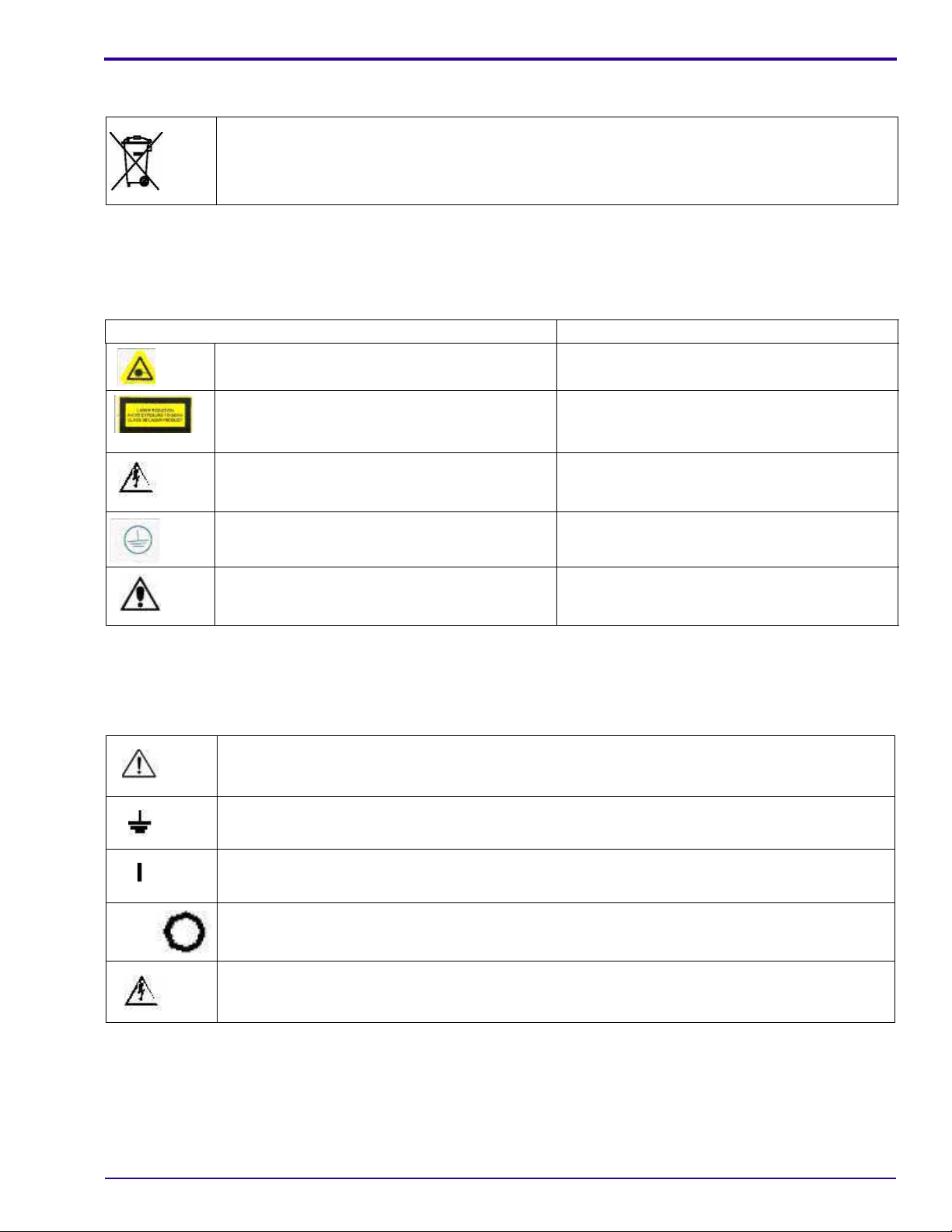
IEC Symbols Used
The system may have labels with one or more of the following symbols. These symbols indicate the IEC standards
to which the system conforms.
Warning, Caution – consult accompanying documents
Protective ground points
Power ON
Power OFF
Caution – Electrical shock hazard
6H4869 11
Page 12
Service Guide
Device-specific Safety Information
Safety Information Consignes de Sécurité
LIFTING HAZARD
DANGER POIDS LOURD
The KODAK Point-of-Care CR 360 scanner
weighs 39 kg (86 lb). Do not try to lift the scanner
by yourself. Always seek assistance from another
person. Lifting equipment that is too heavy may
result in injury to personnel and/or da mag e t o th e
scanner.
WARNING
The KODAK Point-of-Care CR 360 scanner is a
CLASS 1 Laser product.
• Do not remove the scanner cover.
• Cover removal shall be done only by
authorized service personnel!
Le scanner KODAK Point-of-Care CR 360 pèse
39 kg (86 lb). N’essayez pas de porter le scanner
par vous-même. Demandez toujours de l’aide
d’une autre personne. Porter un équipement trop
lourd peut provoquer des dommages physiques
et/ou endommager le matériel.
ATTENTION
Le scanner KODAK Point-of-Care CR 360 est un
produit laser de la Classe 1.
• Ne pas retirer le couvercle du scanner.
• Le retrait du couvercle doit s’effectuer
uniquement par un personnel compétent.
Regulatory Information
Introduction
This product conforms to the following safety standards: IEC 601–1 Medical Electrical Equipment General
Requirements for Safety, EN60601–1–2 Medical Electrical Equipment Electro-Magnetic Compatibility Requirements
and Tests, IEC 60825-1 Safety of Laser Products.
This device complies with 21CFR 1040.10.
CE Conformity
This product conforms to the requirements of council directive 93/42/EEC. The KODAK Point-of-Care CR 360 is a
Class I medical device. The KODAK Point-of-Care CR 360 bears the following mark of conformity:
The name and address of the CE represent ative appears on the back of the front page of this manual.
USA Regulations
The FDA cleared the system for sale in the USA.
Caution
Federal US law restricts this device for sale by or on the order of a physician.
12 6H4869
Page 13

System Description
Section 2: System Description
Introduction
Throughout this manual the KODAK Point-of-Care CR 360 System will be referred to as the Point-of-Care CR 360.
The Point-of-Care CR 360 is designed for the reading of phosphor X-ray screens (CR) by medical professionals.
The system consists of the Point-of-Care CR 360 scanner and the software package that includes:
• The KODAK QC Software that operates the scanner.
• An image viewing and archiving software package t hat supports t he DICOM 3.1 st andard and was approved b y
Carestream Health.
• The system features 8 x 10 in., 10 x 12 in., 14 x 17 in., 9.5 x 9.5 in., 11 x 14 in., 14 x 14 in., 14 x 33 cm, 24 x 30 cm,
and 15 x 30 cm digital image reading and viewing archive.
Note
Throughout this manual Front of the unit ref ers to the side where the cassettes are inserted. Right and Left are as
viewed when facing the front of the unit.
Operational Principles
The Point-of-Care CR 360 is a digital imaging system for image acquisition and processing of static projection
radiography that uses a phosphor screen with energy storage capability as an X-ray image receptor.
After exposure, a laser beam, which stimulates luminescence proportional to the local X-ray exposure, reads the
screen. The luminescence signal is digitized. The data is then subjected to digital image processing.
The Point-of-Care CR 360 enables the user t o read a screen quickly, and then erase it to be ready fo r the next scan.
The scanner is compact and easy to use.
Using the Point-of-Care CR 360 enables medical professionals to “go digital” without changing their work practices
or X-ray equipment.
6H4869 13
Page 14

Service Guide
System Overview
Component Names and Descriptions
Part Name Description
Controller Board The controller board is the main board on the scanner. The controller board
connects the scanner to the host PC workstation via the USB port. The
controller board runs the firmware, and receives operational commands from
the host PC workstation via the USB cable, and transforms the commands to
the appropriate scanner hardware commands. The controller board generates
the +/- 15 Vac to the DPMT and the +/- 12 Vac to the IMCS. It builds the
scanned images and sends them via the same USB cable to the PC
workstation. The controller board serves as the link between all peripherals in
the scanner (i.e., Erase lamp, IMCS, Laser Board, and DPMT)
Integrated Motion Control
System (IMCS) Board
Linear Slide Assembly The linear slide assembly moves the optical head and PM assembly along the
Optical Head Assembly The optical head assembly includes the laser module and the rotation motor
Photo Multiplier Assembly (PM) The photo multiplier (PM) tube collects the photons emitted from the screen and
Roof Assembly and Tray
Assembly
Power Supply The AC/DC power supply provides DC power to the scanner components.
Loader Stepper Assembly The loader stepper assembly extracts the phosphor screen from th e cassette in
Roller Drive Motor Sub-System The roller drive motor pulls the phosphor screen, when loading the phosphor
Laser The laser beam stimulates the phosphor screen.
Laser Board The laser board activates the optical head assembly. The laser board receives
Barcode Reader The barcode reader reads the screen size after th e cassett e is inse rt ed into t he
The motion (IMCS) board controls and drives the four motors:
• Loader motor
• Linear motor
• Rotation motor
• Roller drive motor
The IMCS board receives feedback from the encoders and sensors.
The sensor board is a plug-in board in the IMCS board.
X-axis (slow scan) during the scan.
that rotates the laser tube and a mirror during scanning. The laser module’s
beam is reflected by the revolving mirror to different points on the phosphor
screen inside of the drum. Simultaneously, the optical he ad travels along a
linear axis, so the laser beam covers the full area of the screen one line at a
time (fast scan). Another mirror collects and reflects the light returned from the
screen to the PM assembly window.
transforms the light into a current, which is then converted to voltage and
digitized to pixel value by an ADC.
These two interconnected components receive and direct the cassette into
position in preparation for loading into the drum.
preparation for insertion into the drum, and assists in inserting the phosphor
screen into the cassette. It is powered by the loader motor which works in an
open loop (no encoder).
screen into the drum, and pulls the phosphor screen back into the cassette
when unloading the phosphor screen back into the cassette. The roller motor
has a closed loop control which enables you to change the motor speed and
thus control the erase time.
rotation motor phases and laser power, and enables laser signals. It transfers
the rotation motor encoder signals to th e controller board.
scanner and locked into place.
14 6H4869
Page 15

System Description
Part Name Description
LED Indicator The LED indicator indicates the scanner’s main status such as ready for scan,
erasing, and so on.
Erase Lamps Assembly The erase lamps assembly brightly illuminates the phosphor screen after
scanning, to erase the image so that the screen is ready to be used again.
Erase Lamps Inverter Board The erase lamps inverter board converts the 21 VDC input to high voltage
output which drives the erase lamps (CCFL tubes).
CCFL Board The CCFL board monitors the erase lamps current (CCFL tubes) and the erase
lamps assembly temperature.
Sensor Board The sensor board is a plug-in board in the IMCS board.
Sensors
Roller Motor Forward Limit
Sensor (J502)
Forward limit sensor that stops the roller motor upon reaching th e end of travel
during screen loading.
Autoloop Sensor (J504) Detects that the auto-loop mechanism is in activated position.
Left and Right Limit Sensors
(J515/J516)
Left and right limit sensors indicate that the linear slide assembly has reached
the end of its travel. The right limit sensor (J516) is Home position.
W0 Sensor (J511) The W0 sensor determines the activation and deactivati on of the rollers
according to screen presence at the entrance to the drum.
Z0 Sensor (J505) Detects the presence of the screen in th e drum.
Loader Back Sensor (J508) Back limit sensor that stops the roller motor when moving in a backwards
direction.
Cover Safety Interlock
Sensor (J510)
Detects presence of system cover. When the cover is not detected, the system
motors, laser, and erase assembly will not work.
15x30 Sensor (J512) Detects if the 15 x 30 in. dental adapter is installed.
Cassette In Place Sensor
(J513)
Cassette Hold Sensor
(J514)
Signals to the control system when the cassette is inserted and locked into the
scanner.
Reverse limit sensor that stops the loader motor upon re aching the end of travel
position in a forward direction.
6H4869 15
Page 16
Service Guide
Views of the Point-of-Care CR 360
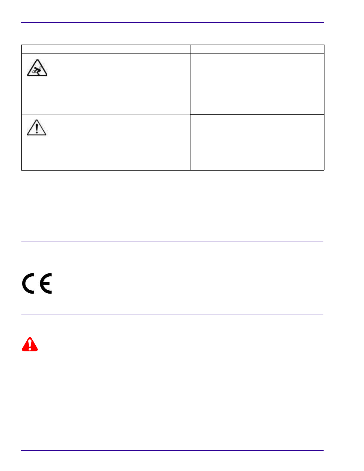
Scanner Front View
Lead screw
LED indicator
Drum
Laser board
Roof assembly
Tray assembly
Scanner Rear View
Erase lamps
inverter board
Erase lamp
board
Off/On switch
Power cord
socket
Connector panel
Controller board
USB outlet
16 6H4869
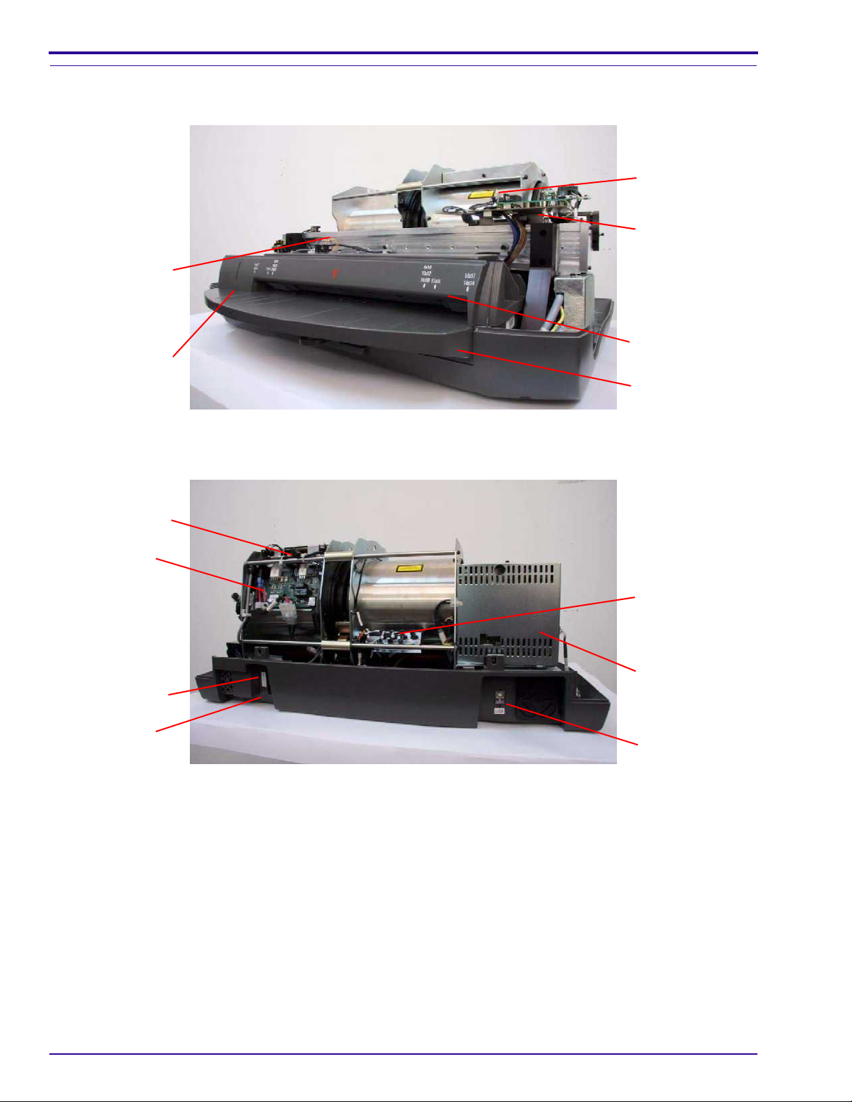
Page 17
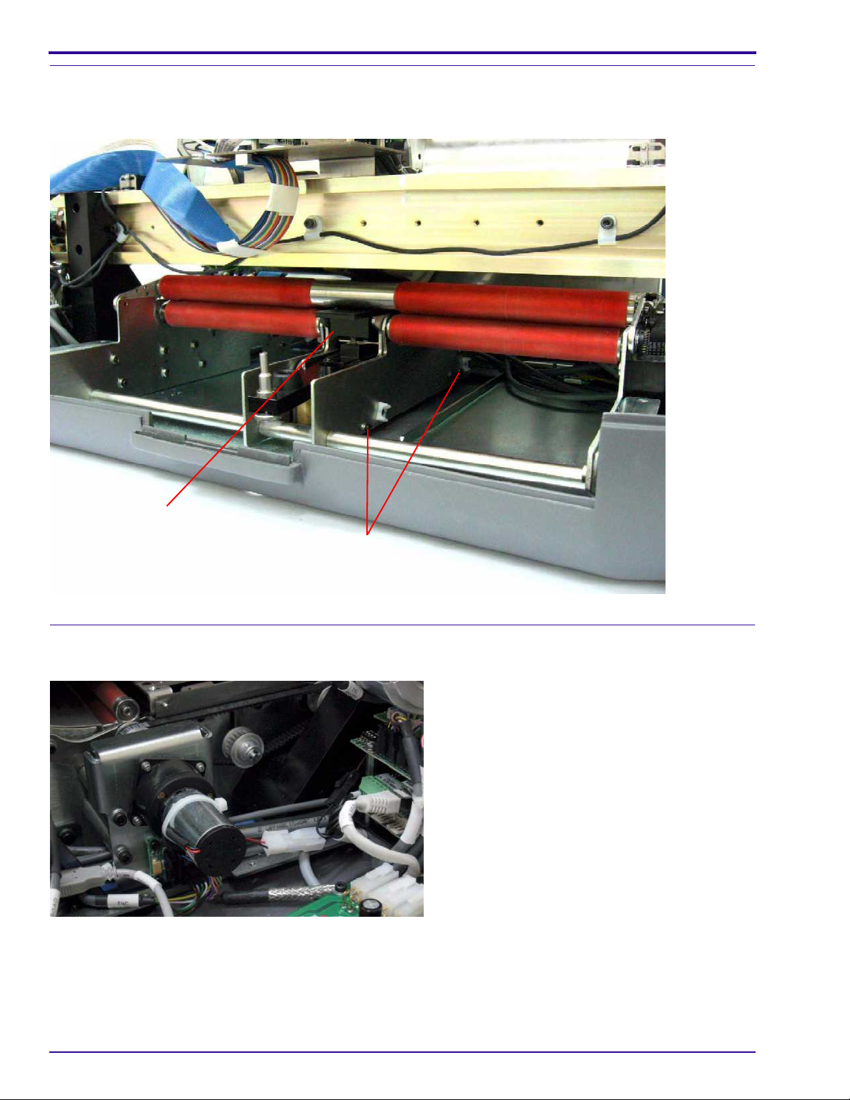
Scanner Left View
PM tube
System Description
Linear motor
Roller drive motor
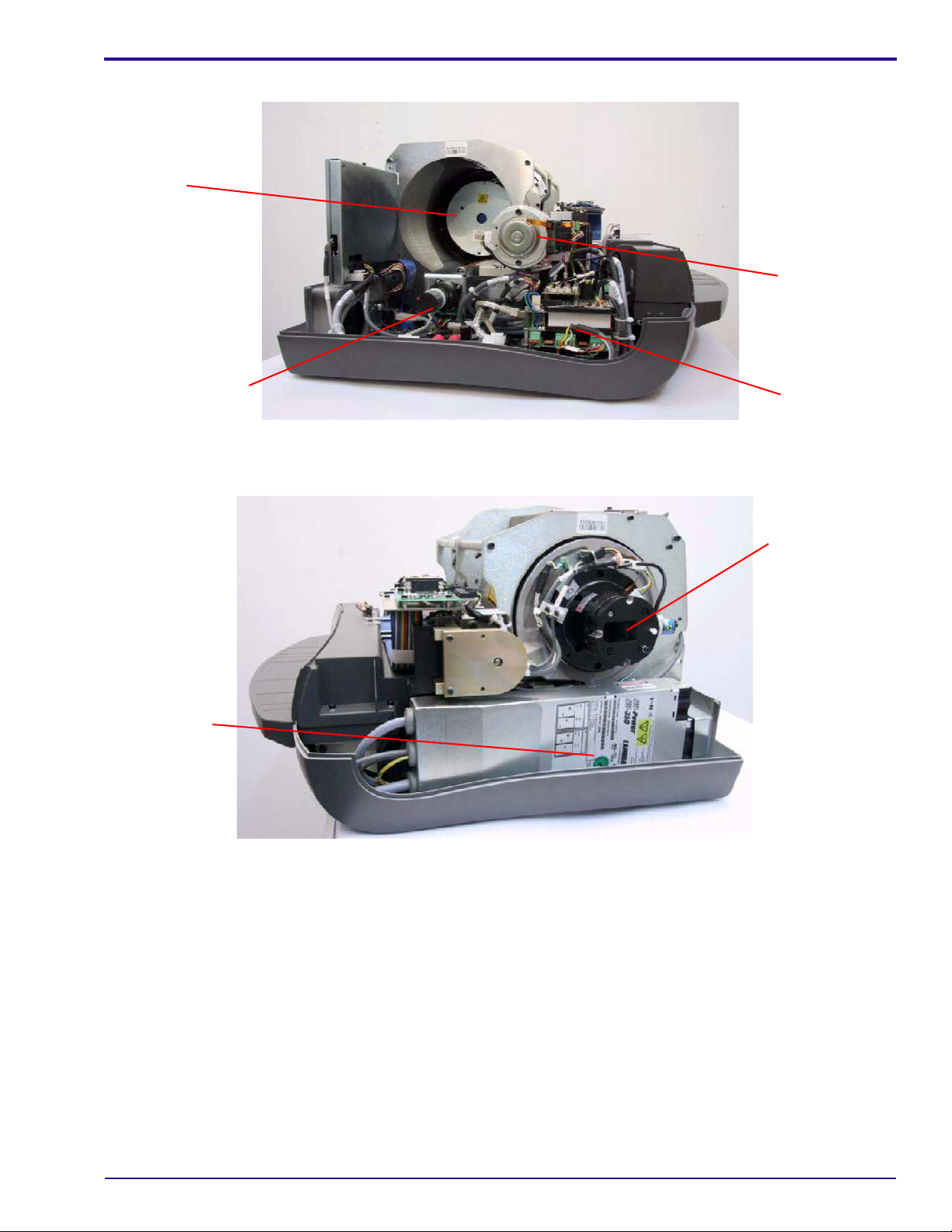
Scanner Right View
Power supply
unit
IMCS board
Laser unit
6H4869 17
Page 18
Service Guide
Component Description
Power Line Filter Module
The power line filter module filters the AC supply to the scanner. The power inlet socket, ON-OFF switch, and two
fuses are located on the module.
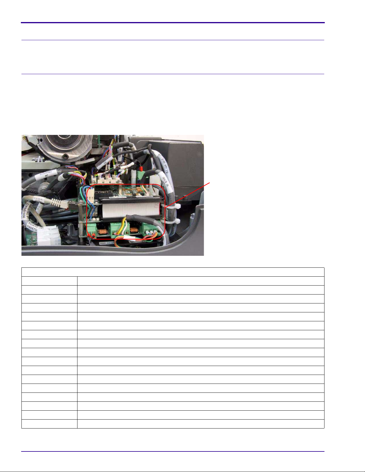
IMCS Board
The IMCS board is a module stacked in four layers. It comprises the motion boar d and the sensor bo ard, which is on
the top layer. The IMCS board controls all four scanner motors and is responsible for all scanner sequences: loading,
scanning, erasing, unloading, and ejecting the cassette.
The motion board and sensor board can be replaced ei ther separately or as a single component. The supplied
replacement unit is an entire IMCS board assembly. If you need to replace one of these boards separately you must
first separate the replacement board from the replacement unit.
Motion board
Sensor Board Connectors
J501 Reserved
J502 Roller Forward Sensor
J503 Reserved
J504 Loop Solenoid
J505 Screen Carriage Sensor (Z0)
J506 Reserved
J507 Reserved
J508 Loader Back Position
J510 Cover Sensor
J511 W0 Sensor
J512 15 x 30 Cassette Adapter Sensor
J513 Cassette Presence Sensor
J514 Cassette Hold Sensor
J515 Left Limit Sensor
J516 Right Limit Sensor (Home Sensor)
J517 Reserved
J519 Reserved
18 6H4869
Page 19
System Description
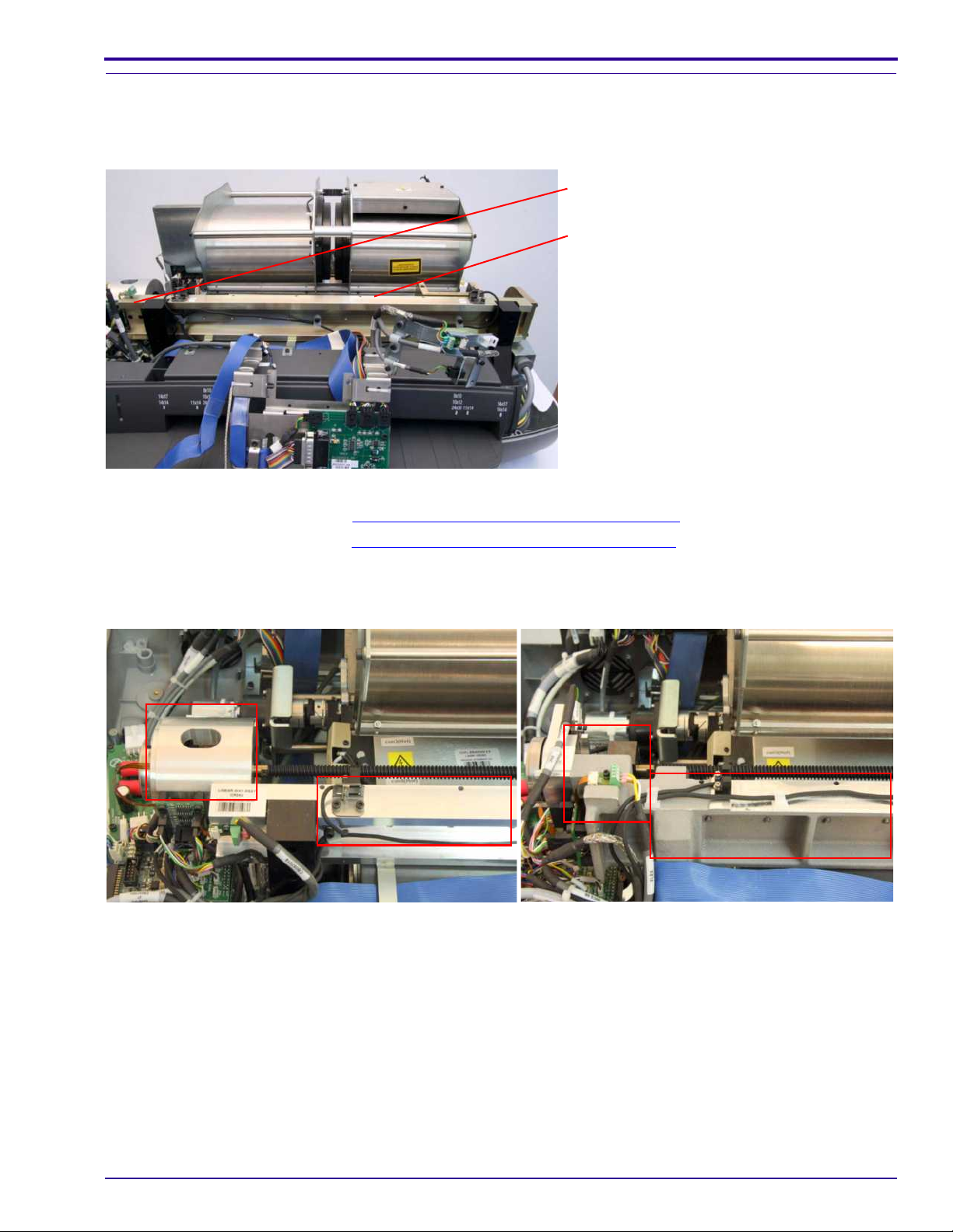
Linear Slide Assembly
Overview
The linear slide assembly moves the PM assembly and the laser within the drum to read the phosphor screen.
Linear motor
Linear screw
There are two replacement procedures for the linear slide assembly:
• Linear screw replacement. See Replacing the Linear Screw Type A
• Linear motor replacement. See Replacing the Linear Motor
Type A on Page 54.
on Page 48.
Two Types of Linear Screws
Type A Type B
6H4869 19
Page 20
Service Guide
Linear Motor
The linear motor operates the linear slide assembly.
Two Types of Linear Motors
Type A
Type B
Optical Head Assembly
The optical head assembly controls the laser module beam. The laser module beam emits the light to energize the
phosphor screen.
Optical head
assembly
Optical head
connector bracket
Laser board
20 6H4869
Page 21
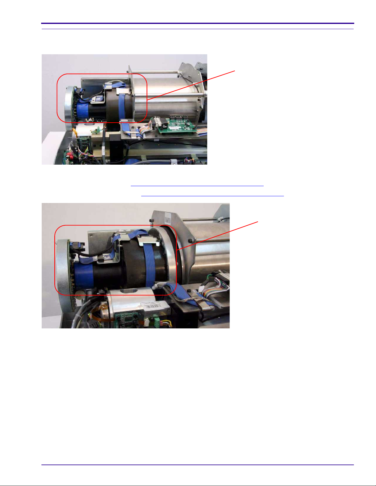
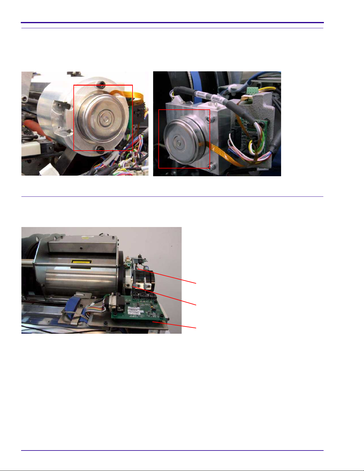
Photo Multiplier Assembly (PM)
The photo multiplier (PM) tube collects the photons emitted from the screen.
PM tube
There are two replacement procedures for the photo multiplier:
• PM board replacement. See Replacing the Photo Multiplier Board
• PM assembly replacement. See Replacing the Photo Multiplier Assembly
on Page 39.
System Description
on Page 41.
Photo Multiplier
assembly
6H4869 21
Page 22
Service Guide
Loader Stepper Assembly
The loader stepper assembly extracts the screen from the cassette and assists in inserting the screen into the
cassette.
Loader pusher
Retainer screws
Roller Drive Motor Assembly
The roller drive motor assembly pulls the phosphor screen from the cassette into the drum.
22 6H4869
Page 23
System Description
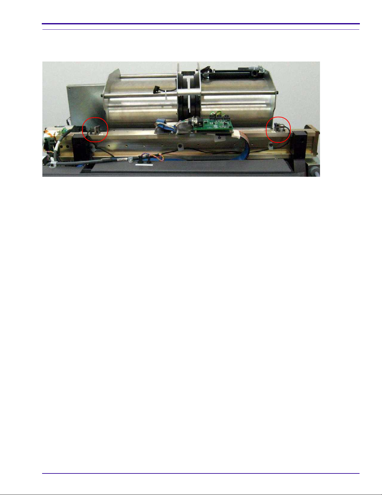
Right and Left Limit Sensors
The right and left limit sensors control the maximum left/ri ght (X-axis) movement of the linear motor of the PM
mounted on the slide.
6H4869 23
Page 24

Service Guide
Section 3: Service Procedures
Service Tools
The following is a list of tools required for service operations:
• Phillips (cross-head) screwdriver (medium)
• Flat screwdriver
• Allen wrenches (metric): 0.89, 1.5, 2, 2.5, 3, 3.5, 4, 5
• Open-ended wrenches (metric): 5.5, 7
• Wire cutters
• Long-nose pliers
• Multi-meter / avo (DVM)
• Safety activation key (SK000100)
• Scanning head alignment gauge (SK00009 9 )
• Trolley roller gauge (0.3 mm and 0.4 mm) (SK000024)
• Safety eyewear (The required laser safety eyewear must be intended for HeliumNeon/PDT lasers, have an
optical density of 4-5 wavelengths of 610-695 nm, and be mar ked as having CE approval.)
24 6H4869
Page 25
Service Procedures
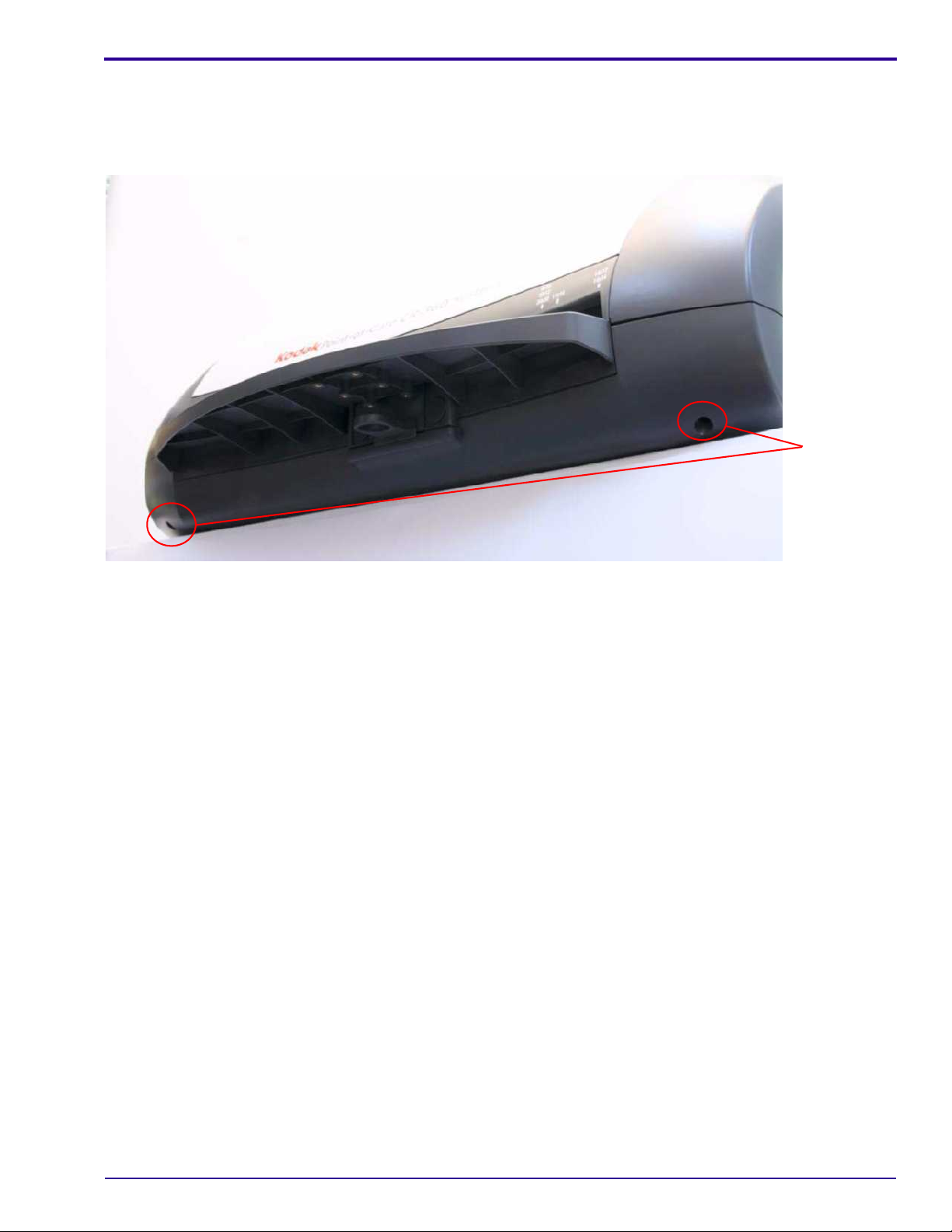
Removing the Scanner Cover
[1] Switch OFF the scanner.
[2] With the system upright, pull the scanner to the edge of the table so that the front side is e xtended slightly o v er
the table edge.
Scanner
cover
screws
[3] Remove the 2 scanner cover screws using a 5 mm Allen wrench.
[4] Remove the 2 scanner co v er screw s at the bac k of the scanner (o ne on each side) using a 5 mm Allen wre nch.
[5] Lift off the cover.
Installing the Scanner Cover
[1] Check (in this order):
a. The scanner is switched OFF.
b. The safety interlock key is not in the interlock.
c. The laser board DIP switch is switched ON.
[2] Install the scanner cover.
[3] Install the 4 scanner cover screws.
[4] Switch ON the scanner.
6H4869 25
Page 26
Service Guide
Activating the Scanner Without the Cover
Activation Procedures
Laser Warning
Do not operate the unit while the la ser is co nnected without proper eye pr otection. Safe ty glasses (see Laser Safety
Instructions on Page 10) must be worn by all personnel in the ar ea of the unit! Only authorized per sonnel may remove
the cover. Before operating the unit without the cove r, disconn ect the laser (see Activating the Scanner Without the
Cover (Laser Deactivated) on Page 26).
When the scanner cover is removed, the safety electrical interl ock switch disconn ects th e er asing CCF L asse mbly,
the laser, and all motors.
To activate the scanner without the cover, use the applicable procedure:
• If the laser is not needed. See Activating the Scanner Without the Cover (Laser Deactivated)
• If the laser is needed. See Activating the Scanner without the Cover (Laser Activated)
on Page 27.
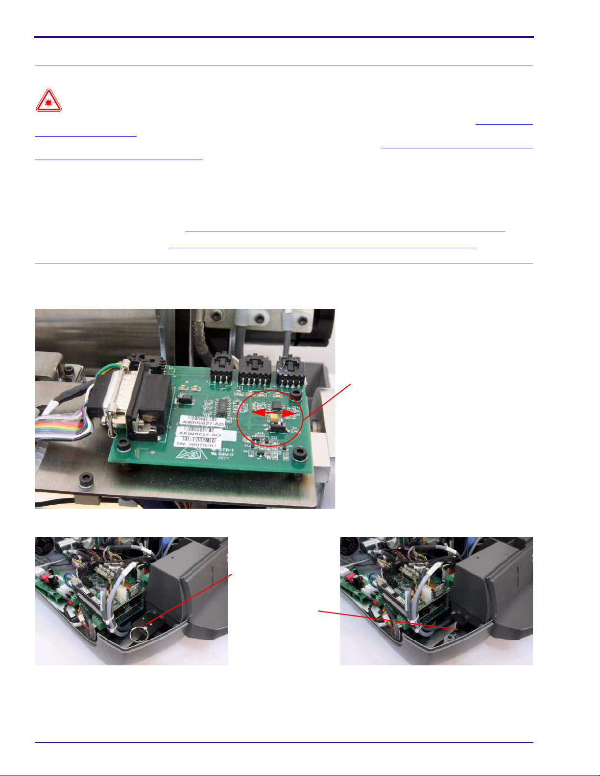
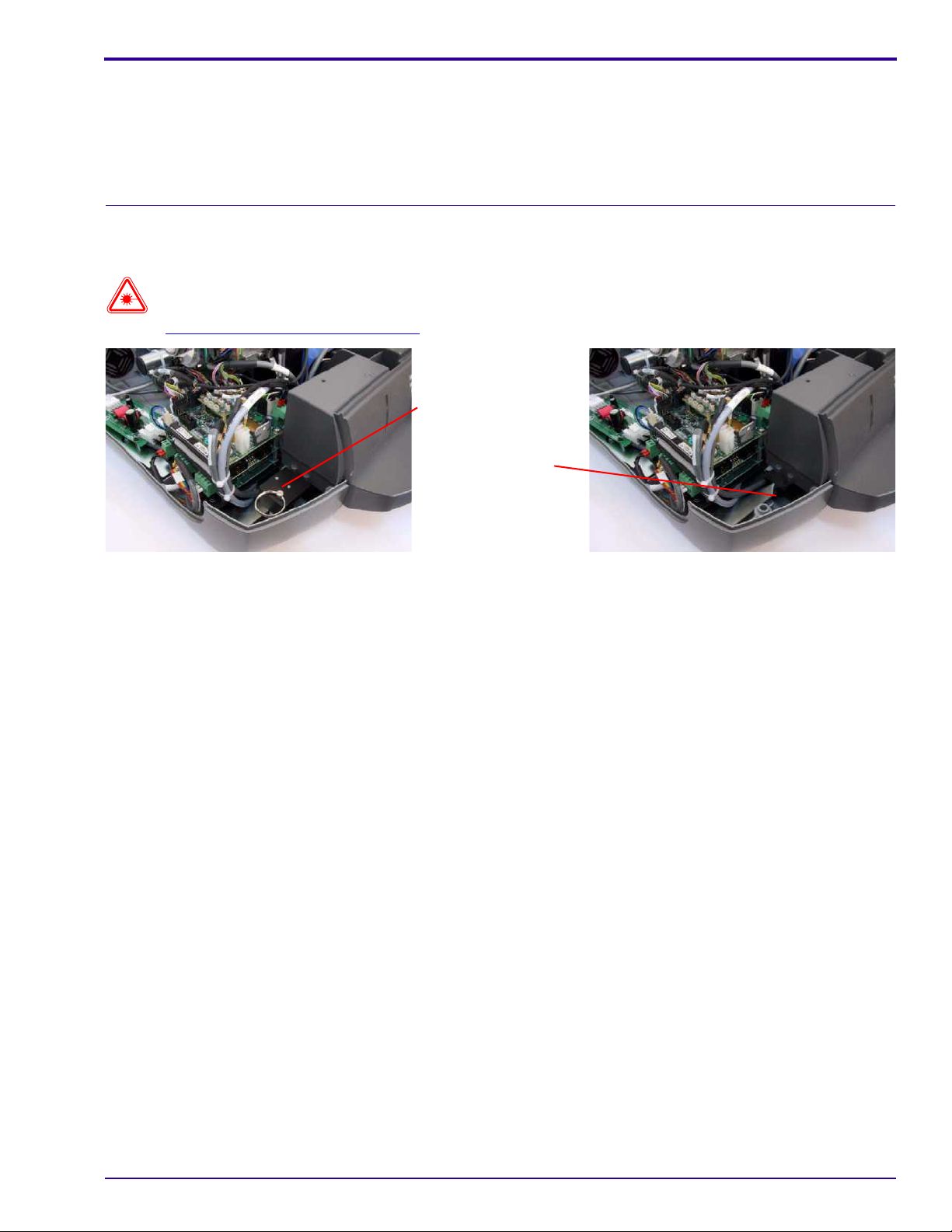
Activating the Scanner Without the Cover (Laser Deactivated)
Before Service Operations
on Page 26.
[1] Switch OFF the DIP switch on the laser board.
Activation key
inserted
Laser board DIP switch
Activation key
not inserted
[2] Insert the safety interlock activation key into the safety interlock to the left of the roof assembly.
[3] Switch ON the scanner and perform the necessar y ope r atio n s.
26 6H4869
Page 27
After Service Operations
After performing service operations, before installing the scanner cover:
[1] Switch OFF the scanner.
[2] Remove the safety interlock activation key from the safety interlock.
[3] Switch ON the DIP switch on the laser board.
Activating the Scanner without the Cover (Laser Activated)
Before Service Operations
Laser Warning
Refer to Laser Safety Instructions on Page 10.
Activation key
inserted
Activation key
not inserted
Service Procedures
[1] Insert the safety interlock activation key into the safety interlock.
[2] Switch ON the scanner and perform the necessary operations.
[3] If the laser is no longer needed, switch OFF the DIP switch.
After Service Operations
After performing service operations, before installing the scanner cover:
[1] Switch OFF the scanner.
[2] Remove the safety interlock activation key from the safety interlock.
[3] If the DIP switch on the laser board is OFF, switch it ON.
6H4869 27
Page 28
Service Guide
Replacing the Power Line Filter Module
Tools Required
• Socket wrench
• 2.0 mm Allen wrench
• 2.5 mm Allen wrench
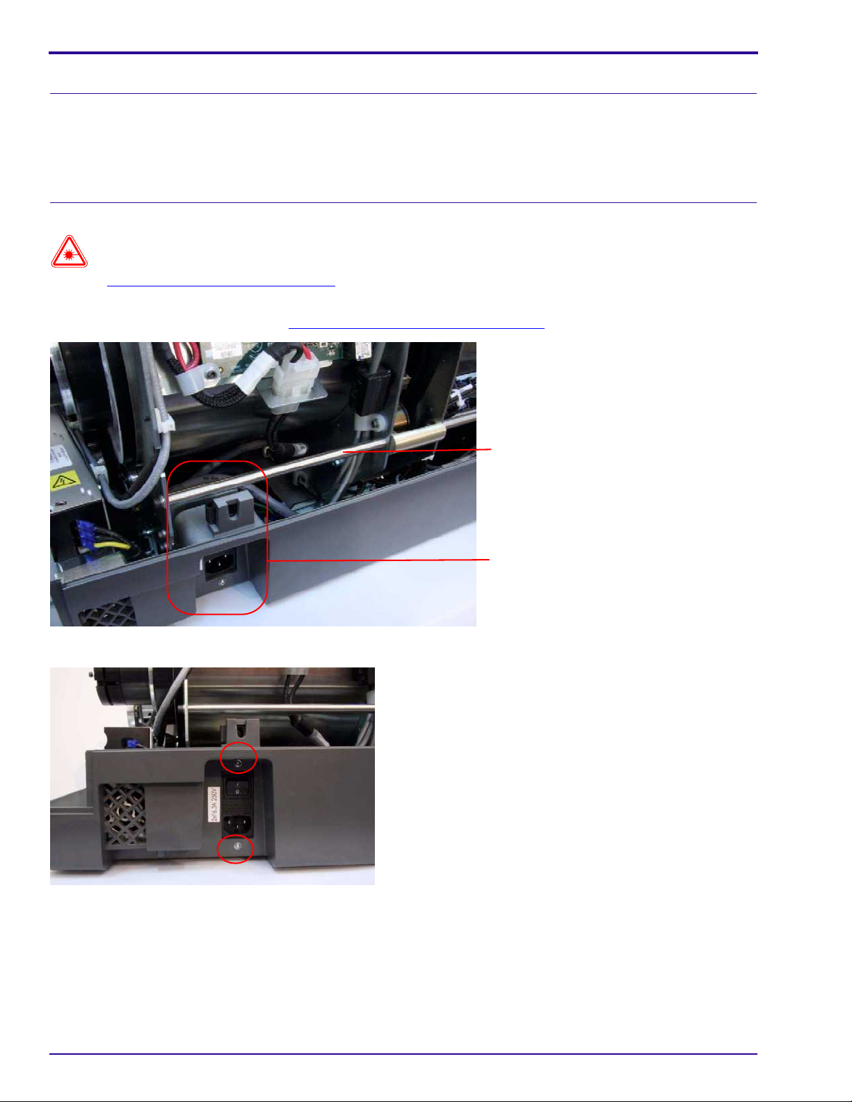
Removing the Power Line Filter Module
Laser Warning
.Refer to Laser Safety Instructions on Page 10.
[1] Switch OFF the power and disconnect the power cable from the power inlet socket of the scanner.
[2] Remove the scanner cover. (See Removing the Scanner Co ver
on Page 25.)
[3] Remove the lower left structure bar using a 2.5 mm Allen wrench.
Structure bar
Power line filter module
[4] Remove the 2 screws above and below the ON/OFF switch using a 2 mm Allen wrench.
28 6H4869
Page 29
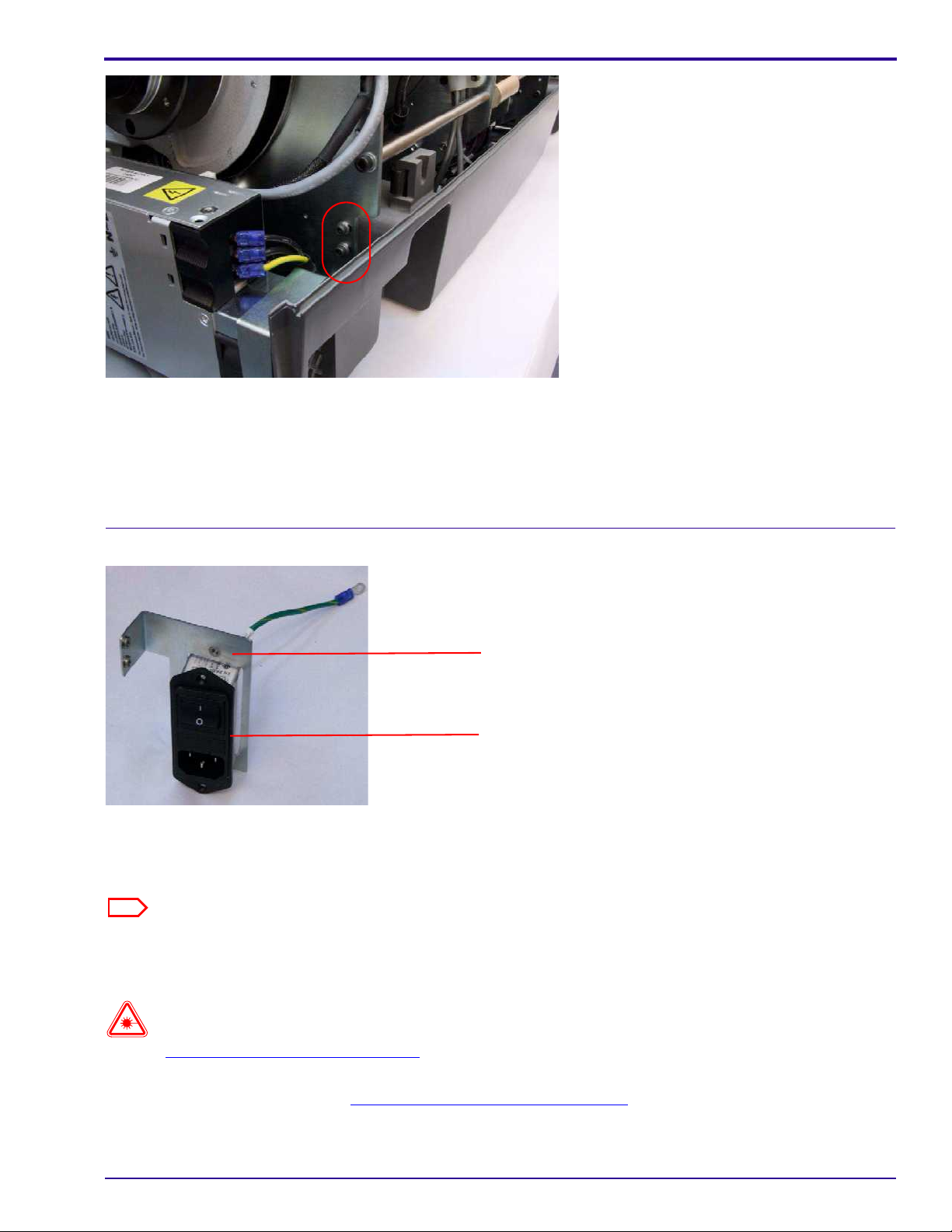
[5] Remove the 2 screw s retaining the module bracket using the 2.5 mm Allen wrench.
[6] Remove the nuts retaining the ground cables to the ground stud using a socket wrench.
[7] Remove the ground cable of the power line filter from the stud.
[8] Disconnect the 2 power connectors.
[9] Remove the module together with the module bracket from the scanner.
Service Procedures
Installing the Power Line Filter Module
Module bracket
Power line filter module
[1] Set the new power line f ilter module into the module bracket.
[2] Insert the module into the scanner.
[3] Connect the 2 power connectors to the module.
Note
Connect black wire No. 1 to P and black wire No. 2 to N.
[4] Connect the 3 ground wires to the stud and tighten the nut.
[5] Insert the bracket screws.
Laser Warning
Refer to Laser Safety Instructions on Page 10.
[6] Connect the system to the main power and confirm that the system is operating properly.
[7] Install the scanner cover. See Installing the Scanner Cover
6H4869 29
on Page 25.
Page 30
Service Guide
Replacing the Fuses
Tools Required
• Flat screwdriver
• Replacement fuses (2)
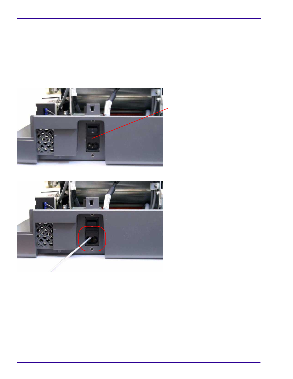
Procedure
[1] Switch OFF the scanner.
[2] Disconnect the scanner from the main power.
Fuse drawer
[3] Locate the fuse drawer on the power inlet module.
[4] Open the drawer using a flat screwdriver, prying gently from the plastic tab.
30 6H4869
Page 31

[5] Remove the blown fuse.
[6] Install a new fuse.
[7] Close the fuse drawer.
[8] Turn on the system.
[9] Verify that the system functions properly.
Service Procedures
6H4869 31
Page 32

Service Guide
Replacing the Controller Board
Tools Required
• 2.5 mm Allen wrench
• 5 mm Allen wrench
Removing the Controller Board
Important
When changing the controller board, first back up the scanne r settings, if it is possible to do so, by copying the Calib
folder to a secure location.
[1] Disconnect the scanner from the main power.
[2] Remove the scanner cover. (See Removing the Scanner Cover
on Page 25.)
[3] Remove the 2.5 mm Allen retaining screw from the top of the controller board housing bracket.
[4] Remove the controller board housing bracket.
[5] Move the PM assembly all the way to the right in order to reach the controller board connectors.
32 6H4869
Page 33

Service Procedures
Cable on right side
of the controller board
Cables on the back
of the controller board
Note
Unfasten the clips on the sides of the wide blue cable to remove it.
Hold the cables by their connectors when remo ving them, not by the cables themselves.
[6] Disconnect the cables from the back of the controller board (accessible from the front side of the scanner).
[7] Disconnect the cables from the right and left sides of the contr oller board.
6H4869 33
Page 34

Service Guide
[8] Remove the 4 screws from the corners of the controller board that fasten it to the bracket using the 2.5 mm Allen
wrench.
[9] Remove the controller board.
Installing the Controller Board
[1] Position t he controller board in the brac ket and install the 4 scre ws connecting the controller boa rd to the brack et
using the 2.5 mm Allen wrench.
[2] Connect the connectors on the left side of th e controller board.
[3] Connect the cable on the right side and the cables at the back of the controller board.
[4] Install the housing bracket and the retainer screw.
[5] Connect the scanner to the PC:
(a) Connect the scanner to the same PC as before.
(b) Switch ON the scanner.
(c) The EEPROM screen appears. Choose Copy disk file to EEPROM, then click OK.
Laser Warning
.Refer to Laser Safety Instructions on Page 10.
34 6H4869
Page 35

Service Procedures
[6] Before installing the scanner cover, perform a test scan. Check that the system functions properly. The preview
image should be black.
[7] Check (in this order):
a. The safety interlock key is not in the interlock.
b. The laser DIP switch is switched ON.
[8] Position the scanner cover without installing the scanner cover screws.
[9] Switch ON the scanner.
[10] Perform a test scan. The preview image should be white.
[11] Install the scanner cover screws.
[12] Go to Settings>Calibration and check that the calibration values are marked with a green check mark. If not
perform a full calibration. (See Calibrations
on Page 114.)
[13] Go to Settings>About and check that all version numbers of the hardware and software are correct.
6H4869 35
Page 36

Service Guide
Replacing the IMCS Board
Tools Required
• 2.5 mm Allen wrench
• 5 mm Allen wrench
• Phillips (cross-head) screwdriver
• Wire cutter
Note
If you replace only the motion board or only the sensor board, return the unused board together with the replaced
board to your Service Representative, noting clear ly which is new and which was replaced.
Removing the IMCS Board
[1] Disconnect the scanner from the main power.
[2] Remove the scanner cover. (See Removing the Scanner Cover
on Page 25.)
Allen screw
[3] Disconnect the connectors from the IMCS board.
[4] Cut the plastic ties.
[5] Remove the four 2.5 mm Allen screws retaining the IMCS board.
[6] Lift the board from the scanner.
36 6H4869
Page 37

Separating the Sensor Board from the Motion Board
[1] Disconnect the scanner from the main power.
[2] Remove the scanner cover. (See Removing the Scanner Cover
[3] Remove the 2 Phillips screws from the sensor board.
Service Procedures
on Page 25.)
Sensor board
[4] Lift the sensor board without disconnecting its connectors and position it on its side.
[5] Remove the connectors from the motion board.
[6] Cut the plastic ties.
[7] Remove the four 2.5 mm Allen screws retaining the motion board and lift the board from the scanner.
6H4869 37
Page 38

Service Guide
Installing the IMCS Board
[1] Connect the connectors to the back of the motion board.
[2] Insert the IMCS board in to the scanner housing.
[3] Install the 4 retaining screws.
[4] Install new plastic ties.
[5] Connect the rest of the connectors to the board.
Note
The connectors on the right are identical. Each connector socket on the board is has a connector number.
[6] If you replaced only the motion board, then attach the sensor board to the motion board by inserting the 2
retaining screws.
Laser Warning
.Refer to Laser Safety Instructions on Page 10.
[7] Before installing the scanner cover, activate the scanner and:
(a) Insert the safety interlock activation key into the safety interlock.
(b) Switch ON the scanner.
(c) Perform a scan to verify that the IMCS board functions properly and that all systems move freely.
(d) Switch OFF the scanner.
(e) Check that the safety interlock key is not in the interlock.
(f) Check that the laser DIP Switch is switched ON.
[8] Install the scanner cover.
[9] Install the scanner cover screws.
[10] Switch ON the scanner.
[11] Perform a scan to verify that the IMCS board functions properly and that all systems move freely.
38 6H4869
Page 39

Replacing the Photo Multiplier Board
Tools Required
• Replacement PM tube
• 3.0 mm right-angle Allen wrench
• 3.5 mm right-angle Allen wrench
Removing the PM Board
Service Procedures
[1] In Settings>Diagnostics, move the linear slide assembly to the left limit.
[2] Disconnect the scanner from the main power.
[3] Remove the scanner cover. (See Removing the Scanner Cover
[4] Disconnect the blue ribbon cable on the PM board.
[5] Remove the two 2.5 mm Allen screws and the 5.5 mm nut retaining the PM board cover.
[6] Remove the cover.
on Page 25.)
Nut
6H4869 39
Page 40

Service Guide
[7] Remove the top bolt screw and the ground connector.
The ground connector
is behind the board
[8] Remove the PM board.
Installing the PM Board
[1] Position the PM board in correct alignment to fit with the PM tube pins.
[2] Install the PM board and the ground connector.
[3] Install the PM board cover and tighten the screws.
[4] Connect the blue PM ribbon.
[5] Check (in this order):
a. The scanner is switched OFF.
b. The safety interlock key is not in the interlock.
c. The laser DIP switch is switched ON.
[6] Install the scanner cover.
[7] Install the scanner cover screws.
[8] Switch ON the scanner.
[9] Perform an offset calibration and a PM gain calibration. (See Offset Calibration
Tuning Procedure on Page 117.)
[10] Perform a scan on a phantom object.
on Page 116 and System Gain
40 6H4869
Page 41

Replacing the Photo Multiplier Assembly
Tools Required
• Replacement PM assembly
• 2.5 mm Allen wrench
• 3.0 mm right-angle Allen wrench
• 3.5 mm right-angle Allen wrench
• Scanning head alignment gauge
Removing the PM Tube
Service Procedures
[1] In Settings>Diagnostics move the linear slide assembly to the left limit.
[2] Disconnect the scanner from the main power.
[3] Remove the scanner cover. (See Removing the Scanner Cover
[4] Disconnect the ground wire connector from the PM board using a 2.5 mm wrench.
[5] Cut the plastic ties retaining the ground wire to the bracket.
[6] Disconnect the blue ribbon cable from the PM board.
[7] Loosen the Allen screws holding the blue ribbon cable in position.
[8] Remove the ribbon cable.
on Page 25.)
Ribbon connector
Allen screws
Ground wire connector
6H4869 41
Page 42

Service Guide
Bracket 2Bracket 1
[9] Loosen Brack et 1 and Brac ket 2 holding the cab les to the PM assem bly using a 3 mm Alle n wrench and 2.5 mm
Allen wrench.
[10] Remove the blu e ribbon cable and ground cable from the PM assembly.
Laser board bracket
screws
Laser board
[11] To remove the PM assembly bracket arm, first remove the 4 screws retaining the laser board bracket to the
linear slide assembly.
[12] Remove the 4 screws that hold the PM assembly bracket arm to the linear slide assembly using a 3 mm Allen
wrench.
Bracket arm
Caution
Stand the PM assembly on the wider end or on the side to prevent damage.
[13] Carefully remove the PM assembly.
42 6H4869
Page 43

Service Procedures
Installing the PM Tube
[1] Insert but do not tighten the 3.5 mm bottom bracket retaining screw.
[2] Insert but do not tighten the 3.5 mm right-side bracket retaining screw.
[3] Move the PM tube forward towards the drum by man ually turning the lead scre w unt il the scre ws align with the
holes.
[4] Insert but do not tighten the retaining screws.
[5] Align the PM with the edge of the drum.
Alignment
gauge
[6] Insert the scanning head alignment gauge with the narr ow parts of the pr ongs betw een the PM t ube and the
drum.
[7] Hold the PM tube against the alignment gauge and tighten the screws.
[8] Move the linear slide assemb ly to the right unt il the gauge is released from between the PM tube an d the drum.
[9] Connect the blue ribbon cable to the top of the PM board.
6H4869 43
Page 44

Service Guide
[10] Install the blue ribbon cable an d the ground cable into the bracket and plastic clip on the PM tube.
[11] Attach to the PM assembly the brackets and plastic clip that hold the blue ribbon cable and the ground cable.
[12] Connect the ground wire connector to the slide body.
[13] Check (in this order):
a. The scanner is switched OFF.
b. The safety interlock key is not in the interlock.
c. The laser DIP switch is switched ON.
[14] Install the scanner cover.
[15] Install the scanner cover screws.
[16] Switch ON the scanner.
[17] Perf orm an offset calibr ation, PM gain calibr ation, and OCPC calibr ation. ( See Offset Calibration
System Gain Tuning P
rocedure on Page 117, and OCPC Process Calibration Procedure on Page 118.)
on Page 116,
[18] Perform a scan on a phantom object.
44 6H4869
Page 45

Replacing the Optical Head Assembly
Tools Required
• Replacement optical head ass em b ly
• 2.0 mm Allen wrench
• 2.5 mm Allen wrench
• 3.0 mm Allen wrench
• Scanning head alignment gauge
Removing the Optical Head Assembly
[1] Disconnect the scanner from the main power.
[2] Move the optical head assembly to the right.
Service Procedures
Laser board
bracket
screws
Laser board
[3] Remove the 4 screws that fasten the laser board bracket to the linear slide assembly.
[4] Disconnect the encoder reader cable CB0570710.
[5] Disconnect the ribbon cable and remove it from the plastic holder.
[6] Disconnect the laser cable at the bracket and the laser cable clamp.
3.0 mm screw
6H4869 45
Page 46

Service Guide
[7] Remove the 3.0 mm Allen screw holding the cable bracket.
3.0 mm screw
Optical head bracket arm
Linear slide assembly end wall
Wrench access
[8] Remove the four 3.0 mm screws retaining the optical head bracket arm. Use a long wrench extended through
the linear slide assembly end wall.
[9] Remove the optical head assembly.
Installing the Optical Head Assembly
Note
Do not touch the blue surface or the stainless surface of the optical head assembly.
[1] Install the optical head assembly and insert the four M4 x 12 screws loosely.
Scanning
head
alignment
gauge
Bracket arm screws
46 6H4869
Page 47

Service Procedures
[2] Insert the thin ends of the alignment gauge prongs between the optical head assembly and the drum.
[3] Tighten the screws.
[4] Manually move the linear slide assembly to the left until the alignment gauge is released from between the
optical head assembly and the drum.
[5] Attach the optical head assembly connector bracket.
[6] Connect:
a. The ribbon cable to the driver.
b. The encoder cable to the encoder.
c. The laser board cable to the laser board.
[7] Install the laser board bracket.
[8] Check (in this order):
a. The scanner is switched OFF.
b. The safety interlock key is not in the interlock.
c. The laser DIP switch is switched ON.
[9] Install the scanner cover.
[10] Install the scanner cover screws.
[11] Switch ON the scanner.
[12] Perform an offset calibration, PM gain calibration, and OCPC calibration. (See Offset Calibration
System Gain Tuning P
rocedure on Page 117, and OCPC Process Calibration Procedure on Page 118.)
on Page 116,
[13] Perform a scan on a phantom object.
6H4869 47
Page 48

Service Guide
Replacing the Linear Screw Type A
Tools Required
• 1.5 mm Allen wrench
• 2.0 mm Allen wrench
• 2.5 mm Allen wrench
Removing the Linear Screw Type A
[1] Disconnect the scanner from the main power.
[2] Remove the scanner cover. (See Removing the Scanner Cover
on Page 25.)
[3] Move the scanning head to the middle of the drum.
Coupling screw
[4] Loosen the coupling screws that secu re the linear scre w using a 1.5 mm Alle n wrench. Chec k that the scre w is
free by turning it while holding the motor.
Angular
contact screws
48 6H4869
Page 49

Service Procedures
[5] Remove the 4 screws from the angular contact using a 2.0 mm Allen wrench.
Side wall screws
[6] Remove the side wall screws .
[7] Move the scanning head to the right together with the linear screw.
[8] Carefully remove the linear screw by mo ving it to the left while holding the scanning head in place. Slightly rotate
the flexure and the scr ew to let it pass freely though the base of the scanning head.
Installing the Linear Screw Type A
Perf orm Removing the Linear Screw Type A on Page 48 in reverse order:
Caution
Do not damage the linear screw’s TEFLON coating while inserting it!
[1] Install the left side wall and secure the screws.
[2] Install the flexure screws.
[3] Install the four angular contact screws.
[4] Install the coupling screw and fasten the nut.
6H4869 49
Page 50

Service Guide
Replacing the Linear Screw Type B
Tools Required
• 1.5 mm Allen wrench
• 2.5 mm Allen wrench
• 3.0 mm Allen wrench
• 4.0 mm Allen wrench
• Alignment gauge
Removing the Linear Screw Type B
[1] Disconnect the scanner from the main power.
[2] Remove the scanner cover. (See Removing the Scanner Cover
on Page 25.)
[3] Remove the two 2.0 mm Allen screws closest to the linear screw that secure the linear motor coupling.
Motor
flex cable
Encoder reader
cable
[4] Disconnect the motor flex cable.
50 6H4869
Page 51

[5] Disconnect the encoder reader cable (J1).
Positioning pins
Note
When removing the linear motor, make sure the positioning pins are in place.
[6] Remove the two 4.0 mm Allen screws securing the linear motor and gently remove the motor.
Service Procedures
[7] Remove the 3.0 mm Allen screw on the flexure.
6H4869 51
Page 52

Service Guide
[8] Remove the two 5.0 mm mounting screws securing the linear screw assembly to the side block.
[9] Gently pull out the linear screw with its components.
Installing the Linear Screw Type B
Caution
To avoid damaging the linear screw, make sure it does not contact other parts of the system.
[1] Gently insert the new linear screw in its position:
(a) Position the flexure so the hole is facing up. (See figure s ab ov e.)
(b) Align the bearing on the right side of the linear screw with the hole in the slide block.
[2] Insert but do not tighten the two 5.0 mm mounting screws to the mounting block.
[3] Take the positioning pins from the motor holder. (See Step 6
gauge.
[4] Align the gauge with the edge of the side block.
[5] Insert the alignment gauge and secure the two 4.0 mm Allen screw s, securing the mounting block.
on page 51) and place them in the alignment
[6] Remove the alignment gauge.
[7] Secure the flexure with the 3. 0 mm Allen screw.
[8] Replace the linear motor and secure it with the two 4.0 mm Allen screws.
Note
Make sure the positioning pins are in place.
[9] Secure the coupling with the two 2.0 mm Allen screws.
[10] Connect:
(a) Flex cable
(b) Encoder reader cable (J1)
52 6H4869
Page 53

Service Procedures
Test Procedure
Laser Warning
When a service operation is taking place with the cover r emoved, disconnect the lase r according to the procedur e in
Activating the Scanner Without the Cover (Laser Deactivated)
service procedure, wear protective safety glasses at all times.
Before installing the scanner cover, confirm that the left and right limit sensors function properly:
on Page 26. If the laser must be activated during the
[1] Go to Settings>Diagnostics>Motion.
[2] In the Linear Motor section, enter 5 in Required Speed field.
[3] Click Set.
[4] In the Linear Motor section, click << to activate the linear motor until it reaches the left limit sensor.
[5] Click >> to move the motor until it reaches the right limit sensor.
[6] Verify that the indicator light illuminates.
[7] In the Linear Motor section, enter 10 in the Required Speed field.
[8] Repeat Step 3
- Step 6.
6H4869 53
Page 54

Service Guide
Replacing the Linear Motor Type A
Tools Required
• 3.0 mm Allen wrench
• 2.0 mm Allen wrench
• 1.5 mm Allen wrench
• 0.89 mm Allen wrench
Removing the Linear Motor Type A
[1] Disconnect the scanner from the main power.
[2] Remove the scanner cover. (See Removing the Scanner Cover
on Page 25.)
Motor flex cable
[3] Disconnect the motor flex cable.
[4] Disconnect the encoder reader cable.
Allen screws
Encoder reader cable
[5] Remove the two 2.0 mm Allen screws from the encoder reader connector.
54 6H4869
Page 55

Service Procedures
[6] Remove the encoder reader.
Coupling screws
[7] Remove the tw o 1.5 mm Allen scre ws fr om the linear motor coupling. Che c k that the moto r revolves freely and
independently of the lead screw.
[8] Remove the two 3.0 mm retaining screws.
[9] Remove the linear motor.
[10] Remove the 0.89 mm Allen screw from the encoder.
[11] Remove the encoder from the linear motor axis.
6H4869 55
Page 56

Service Guide
Installing the Linear Motor Type A
1.5 mm gap
[1] Install the old encoder on the new linear motor. Before tightening the 0.89 mm Allen screw, position the encoder
with a 1.5 mm gap between the encoder and the motor body. Use the 1.5 mm Allen wrench to set the gap.
[2] Install the linear motor on the scanner and secure the 3.0 mm Allen screws.
[3] Install the linear encoder board to the linear slide assembly.
[4] Secure the coupling screws.
[5] Attach the encoder reader. Make sure that the reader is positioned in the center before fastening the 2.0 mm
Allen screws.
[6] Attach the linear motor flex cable.
[7] Before replacing the scann er cover, perform this test:
(a) Go to Settings>Diagnostics>Motion.
(b) Click the linear motor left and right arrows to move the slide from side to side.
(c) Check that the optical head assemb ly mo v es smoo thly and th at there is no interference in the movement
of the wires.
[8] Check (in this order):
a. The scanner is switched OFF.
b. The safety interlock key is not in the interlock.
c. The laser DIP switch is switched ON.
[9] Install the scanner cover.
[10] Install the scanner cover screws.
[11] Switch ON the scanner.
56 6H4869
Page 57

Service Procedures
[12] After replacing the scanner cover:
(a) Go to Settings>Diagnostics>Motion.
(b) Click the linear motor left and right arrows to move the slide from side to side.
(c) Check that the optical head a ssembly moves smoothly and that there is no interference in the movement
of the wires.
[13] Perform a flat field scan and check the origin. If the image is not centered, perform an origin calibration. (See
Origin Calibration
on Page 115.)
[14] After performing the origin calibration perform a flat field scan to verify that the calibration was successful.
6H4869 57
Page 58

Service Guide
Replacing the Linear Motor Type B
Tools Required
• 3.0 mm Allen wrench
• 2.0 mm Allen wrench
• 1.5 mm Allen wrench
• 0.89 mm Allen wrench
Removing Type B Linear Motor
[1] Disconnect the scanner from the main power.
[2] Remove the scanner cover. (See Removing the Scanner Cover
Linear motor ribbon
on Page 25.)
[3] Disconnect the encoder cable.
[4] Disconnect the linear motor ribbon.
Encoder cable
[5] Remove the 2 screws securing the coupling to the linear screw using the 1.5 mm Allen wrench.
58 6H4869
Page 59

Service Procedures
[6] Remove the 2 screws securing the mot or assembly to the linear slide assembly using the 3 mm Allen wrench.
Encoder reader
[7] Gently pull out the linear motor assembly.
[8] Remove the 2 scre ws securing the encod er re ade r to t he linear m ot or asse mbly using the 2 mm Allen wrench.
[9] Remove the encoder reader from the linear motor assembly.
6H4869 59
Page 60

Service Guide
[10] Remove the 2 screws securing the coupling adjacent to the encoder disc using the 1.5 mm Allen wrench.
[11] Remove the coupling.
[12] Loosen the screw securing the encoder disc to the motor using the 0.89 Allen wrench.
[13] Remove the encoder disc.
60 6H4869
Page 61

[14] Remove the 3 screws securing the linear motor to the bracket using the 2 mm Allen wrench.
Service Procedures
[15] Remove the linear motor from the bracket.
Installing the Linear Motor Type B
[1] Install the new linear motor.
[2] Install the 3 screws securing the linear motor to the bracket using the 2 mm Allen wrench.
[3] Install the encoder disc, pulley side face down, as shown in the figure above .
Note
Do not tighten the screw securing the encoder disc to the motor.
6H4869 61
Page 62

Service Guide
[4] Install the encoder reader.
Aligned disc
Note
The encoder disc should be aligned with but not touch the encoder reader.
[5] Install the 2 screws securing the encoder reader to the linear motor assembly using the 2 mm Allen wrench.
[6] Tighten the screw securing the encoder disc to the mo to r usin g the 0. 89 Allen wren ch .
Note
Keep the encoder disc as centered as possible so that it does not touch any surface.
[7] Install the coupling.
[8] Tighten the 2 screws securing the coupling adjacent to the encoder disc using the 1.5 mm Allen wrench.
[9] Install the linear motor assembly.
[10] Install the 2 screws securing the linear motor assembly to the linear slide assembly using the 3 mm Allen
wrench.
[11] Tighten the 2 screws securing the coupling to the linear screw using the 1.5 mm Allen screw.
[12] Connect the encoder cable.
[13] Connect the linear motor ribbon.
[14] Before replacing the scanner cover, perform this test:
Linear Slide Test
(a) Go to the Settings>Diagnostics>Motion.
(b) Click the linear motor left and right arrows to move the slide from side to side.
(c) Check that the optical head assemb ly mo v es smoo thly and th at there is no interference in the movement
of the wires.
62 6H4869
Page 63

Service Procedures
[15] Check (in this order):
1. The scanner is switched OFF.
2. The safety interlock key is not in the Interlock.
3. The laser DIP switch is switched ON.
[16] Install the scanner cover.
[17] Install the scanner cover screws.
[18] Switch ON the scanner.
[19] After replacing the scanner cover:
(a) Go to the Settings>Diagnostics>Motion.
(b) Click the linear motor left and right arrows to move the slide from side to side.
(c) Check that the optical head a ssembly moves smoothly and that there is no interference in the movement
of the wires.
[20] Perform a flat field scan and check the origin. If the image is not centered, perform an origin Calibration. (See
Origin Calibration
on Page 115.)
[21] After performing the origin calibration perform a flat field scan to verify that the calibration was successful.
6H4869 63
Page 64

Service Guide
Replacing the Roller Drive Motor Assembly
Tools Required
• 3.0 mm Allen wrench
• 1.0 mm Allen wrench
Removing the Drive Roller Motor Assembly
[1] Disconnect the scanner from the main power.
[2] Remove the scanner cover. (See Removing the Scanner Cover
[3] Move the PM assembly into the drum.
Screw
on Page 25.)
[4] Disconnect the white roller drive motor connector from the connector panel.
Note
There are two types of washers, flat and spring. The washers must be removed and installed in order.
Motor encoder board
64 6H4869
Page 65

Service Procedures
[5] Remove the three 3.0 mm screws from th e base of the roller drive motor assembly and pull ba ck the roller drive
motor assembly.
Roller motor connector
Motor encoder board
Roller motor bracket
[6] Disconnect the 2 connectors from the motor encoder board.
Installing the Roller Drive Motor
[1] Connect the 2 motor encoder board connectors.
[2] Install the roller drive motor. The roller drive motor cog drive mechanism must fit into the drive adapter.
[3] Install the three 3.0 mm Allen screws.
[4] Connect the white roller drive motor connector to the connector panel.
[5] Before replacing the scanner cover:
(a) Go to Setup>Diagnostic>Motion.
(b) Operate the rollers forward and backward (Load, Unload).
(c) Load a cassette into the scanner and check that the scanner loads and unloads the cassette correctly.
6H4869 65
Page 66

Service Guide
[6] Check (in this order):
a. The scanner is switched OFF.
b. The safety interlock key is not in the interlock.
c. The laser DIP switch is switched ON.
[7] Install the scanner cover.
[8] Install the scanner cover screws.
[9] Switch ON the scanner.
[10] Load and unload a cassette a few times to verify that the rollers are functioning properly.
66 6H4869
Page 67

Service Procedures
Replacing the Loader Stepper Assembly
Tools Required
• Cassette Loader Kit
• Long-shaft 2.5 mm Allen wrench
• 2.5 mm x 100 mm cable ties
• Wire cutters
•Tape
Removing the Loader Stepper Assembly
[1] Disconnect the scanner from the main power.
[2] Remove the scanner cover. (See Removing the Scanner Cover
[3] Remove the roof assembly and the tray assembly. (See Removing the Roof Assembly
Removing the Tray Assembly
[4] Disconnect the stepper motor cable CB0 57022.
[5] Disconnect sensor CB057040 from J508 on the connector panel.
[6] Remove the 4 screw s that attach the loader stepper assembly to the loader frame using the 2.5 mm Allen
wrench.
on Page 85.)
on Page 25.)
on Page 83 and
Caution
Be sure to remove the cables carefully.
[7] Pull the loader stepper assembly towards the front of the unit and carefully remove it from the unit.
Installing the Loader Stepper Assembly
[1] Pass the stepper motor cables under the drum.
[2] Install the two Allen screws in the back.
[3] Install the loader stepper assembly into the motor frame.
[4] Insert but do not tighten the front two 2.5 mm screws.
[5]
Connect the sensor cable to the sensor board and the motion cab le to the motion board and f asten the cable tie s.
[6] Adjust the loader pusher position. (See Adjustment Procedure on Page 129.)
[7] Before replacing the scanner cover:
(a) Go to Setup>Diagnostic>Motion.
(b) Operate the rollers forward and backward (Load/unload).
(c) Load a cassette into the scanner and check that the scanner loads and unloads the cassette correctly.
6H4869 67
Page 68

Service Guide
[8] Check (in this order):
a. The scanner is switched OFF.
b. The safety interlock key is not in the interlock.
c. The laser DIP switch is switched ON.
[9] Install the scanner cover.
[10] Install the scanner cover screws.
[11] Switch ON the scanner.
[12] Load/unload a cassette a few times to verify that the rollers are functioning properly.
68 6H4869
Page 69

Replacing the Laser Board
Tools Required
• 2.5 mm Allen wrench
Removing the Laser Board
[1] Disconnect the scanner from the main power.
[2] Remove the scanner cover. (See Removing the Scanner Cover
Service Procedures
on Page 25.)
[3] Disconnect the connectors on the laser board.
[4] Remove four 2.5 mm screws from the laser board.
[5] Remove the laser board.
6H4869 69
Page 70

Service Guide
Installing the Laser Board
[1] Place the new laser board in position and install the four 2.5 mm screws.
[2] Connect the connectors to the laser board.
Laser Warning
See Laser Safety Instructions on Page 10.
[3] Before installing the scanner cover, perform a scan. Make sure that the laser unit is functioning properly and
that a steady beam is produced.
[4] Check (in this order):
a. The scanner is switched OFF.
b. The safety interlock key is not in the interlock.
c. The laser DIP switch is switched ON.
[5] Install the scanner cover.
[6] Install the scanner cover screws.
[7] Switch ON the scanner.
[8] After installing the scanner cover , perf orm a scan. Make sure that the laser unit is functioning properly and that
a steady beam is produced.
[9] Perform a scan on a phantom object to check that the quality of the scan is good.
70 6H4869
Page 71

Service Procedures
Replacing the Power Supply
Tools Required
• Power supply kit (SK000088)
• Long-shaft 7 mm socket wrench
• Long-shaft 2.5 mm Allen wrench
• Phillips (cross-head) screwdriver
Removing the Power Supply Unit
Note
After installation of the new power supply, mark the number 1 in the modification label located at the back of the
scanner.
[1] Disconnect the scanner from the main power.
[2] Remove the scanner cover. (See Removing the Scanner Cover
on Page 25.)
Allen screw
[3] Loosen the 2 Allen screws retaining the U bracket.
[4] Slide the bracket to the side.
[5] Remove the black plastic cover.
U bracket
Plastic
cover
Allen screw
6H4869 71
Page 72

Service Guide
[6] Unscrew the 3 power cable lugs with a cross-head screwdriver.
Caution
Make sure not to lose any screws or washers in the machine.
Each screw has a spring (locking) washer and a regular washer.
[7] Remove the two 7 mm nuts using a long-shaft socket wrench.
[8] Remove the 2 nuts with the 4 washers.
[9] Remove the 2 plastic cable holders.
72 6H4869
Page 73

[10] Pull the cables out of the way.
[11] Remove the 2.5 mm Allen screw (set screw) and washer.
[12] Remove the 2.5 mm Allen screw (cone).
[13] Remove the cover of the power supply cable terminal.
[14] Gently lift the power supply out of the scanner.
Service Procedures
6H4869 73
Page 74

Service Guide
[15] Remove all 7 cables connected to the power supply, while ensuri ng that no wa shers or scre ws have be en lost
in the system.
[16] Turn the power supply on its underside and remove the four 2.5 mm Allen screws (cone).
[17] Slide the power supply out of the power supply housing bracket.
74 6H4869
Page 75

Installing the Power Supply Unit
[1] Slide the new power supply into the power supply housing bracket.
[2] Turn over the power supply and install the four 2.5 mm Allen screws (cone).
CB057003
Number-1
and the
Ground cable
CB057003
Number-3
Service Procedures
CB057003
Number-2
CB057003
Number-4
CB057058
Number-1
CB057058
Number-2
[3] Install the 7 cables, while ensuring that no washers or screws have been lost in the system.
Fan grill
Caution
Be careful not to damage the fan grill when sliding the new power supply into its housing.
[4] Gently install the power supply into the scanner.
6H4869 75
Page 76

Service Guide
[5] To install the cover of the power supply cable terminal:
a. Install the 2.5 mm Allen screw (set screw) and washer.
b. Install the 2.5 mm Allen screw (cone).
[6] Place the cables back in the two plastic cable holders and close the two cable holders.
[7] Install the two 7 mm nuts with a long-shaft socket wrench.
Cable 1
[8] Replace the 3 power cables with a cross-head screwdriver.
Note
• The first (top) cable is marked 1.
• The second cable is marked 2.
• The third cable is ground.
[9] Install the black plastic cover.
[10] Slide the bracket back in its place.
[11] Install the 2 Allen screws holding the bracket.
[12] Install the scanner cover.
76 6H4869
Page 77

Replacing the Erase Lamps Assembly
Tools Required
• 2.5 mm Allen wrench
• 3.0 mm Allen wrench
• 2.5 x 100 mm cable ties
• Wire cutters
Removing the Erase Lamps Assembly
[1] Disconnect the scanner from the main power.
[2] Remove the scanner cover. (See Removing the Scanner Cover
[3] Bring the drive head to the middle.
Service Procedures
on Page 25.)
J4
J3
[4] Disconnect cable CB000024 from the erase lamp board (J3, J4).
Con 3
Con 4
Con 5
Con 6
[5] Disconnect cable CB000023 (connectors 3, 4, 5, and 6) from the erase lamps inverter board.
Note
Do not remove the cable from the cable holders on the erase lamps assembly.
[6] Remove the erase lamp cable from the cable holders on the base of the scanner.
[7] Cut the wire ties holding the cable with the wire bundles on the base of the scanner.
6H4869 77
Page 78

Service Guide
[8] Move the optical head assembly all the way to the right.
Erase lamps
assembly bracket
Erase lamps assembly bracket
retaining screws
[9] Remove the two 2.5 mm retaining screws from the left side of the erase lamps assembly.
[10] Remove the erase lamps assembly retainer bracket from the left side.
[11] Pull the erase lamps assembly out of the drum from the lef t side of the scanner.
Installing the Erase Lamps Assembly
[1] Install the erase lamps assembly into the drum. Make sure that the pins on the right side fit into the bracket..
[2] Install the retainer bracket:
(a) Slide it between the assembly side and the belt.
(b) Install the two 2.5 mm Allen screws holding it in position.
[3] Secure the cables with wire ties to the wire bundles and cable holders.
[4] Connect cable CB000023 to the erase lamps inverter board (make sure to insert the connectors by number).
[5] Connect cable CB000024 from the erase lamp board (J3, J4).
Laser Warning
See Laser Safety Instructions on Page 10.
78 6H4869
Page 79

[6] Before replacing the scanner cover:
(a) Perform a scan. Check that all the motors are functioning properly.
Service Procedures
(b) Go to Settings>Diagnostic>Erasing.
(c) Activate each set of erase lamps and check that a current is generated.
[7] Check (in this order):
a. The scanner is switched OFF.
b. The safety interlock key is not in the interlock.
c. The laser DIP switch is switched ON.
[8] Install the scanner cover.
[9] Install the scanner cover screws.
[10] Switch ON the scanner.
[11] Perform this test procedure:
(a) Go to Settings>Diagnostics>Erasing.
(b) Activate erase lamps Group 1. Check that the current reading is between 2800 mA and 3600 mA.
6H4869 79
Page 80

Service Guide
Replacing the Erase Lamps Fuse
Tools Required
• Flat screwdriver
Installing the Erase Lamps Fuse
[1] Remove the scanner cover. (See Removing the Scanner Cover on Page 25.)
[2] Locate the fuse housing and open the fuse housing cup.
[3] Press and turn the fuse housing cup with the flat screwdriver to remove it.
[4] Remove the old fuse.
[5] Insert the new fuse.
[6] Replace the fuse housing cup.
[7] Check (in this order):
a. The scanner is switched OFF.
b. The safety interlock key is not in the interlock.
c. The laser DIP switch is switched ON.
[8] Install the scanner cover.
[9] Install the scanner cover screws.
[10] Switch ON the scanner.
Test Procedure
Perfo rm this test procedure:
[1] Go to Settings>Diagnostics>Erasing.
[2] Activate erase lamp s Group 1 . Chec k that th e current rea ding is betw een 2800 mA and 3600 mA. (See Step b
on page 79
.)
80 6H4869
Page 81

Replacing the Erase Lamp Board
Tools Required
• Allen 2.5 mm wrench
Removing the Erase Lamp Board
Caution
High Voltage! Do not proceed without disconnecting the scanner from the main power.
[1] Disconnect the scanner from the main power.
[2] Remove the scanner cover. (See Removing the Scanner Cover
on Page 25.)
Inverters
Retainer
screws
Service Procedures
Connectors
[3] Disconnect all the connectors from the erase lamp board.
[4] Remove the three 2.5 Allen screws from the erase lamp board and remove the board.
Installing the Erase Lamp Board
[1] Install the 3 retainer screws connecting the board to the drum.
[2] Connect the connectors. (Note that the conn ector numbers must be the same as the Con numbers.)
[3] Before installing the scanner cover:
(a) Go to Settings>Diagnostic>Erasing.
(b) Activate erase lamps Group 1
(c) Check that the current reading is between 2800 mA and 3600 mA. (See Step b
[4] Check (in this order):
a. The scanner is switched OFF.
b. The safety interlock key is not in the interlock.
c. The laser DIP switch is switched ON.
[5] Install the scanner cover.
[6] Install the scanner cover screws.
[7] Switch ON the scanner.
on page 79.)
6H4869 81
Page 82

Service Guide
Replacing the Erase Lamps Inverter Board
Tools Required
• Allen 2.5 mm wrench
Removing the Erase Lamps Inverter Board
CautionCaution
High Voltage
[1] Disconnect the scanner from the main power.
[2] Remove the scanner cover. (See Removing the Scanner Cover
on Page 25.)
Erase lamps board
[3] Disconnect the connectors from the erase lamps inverter board.
[4] Remove the 4 Allen screws from the erase lamps inverter board and remove the board.
Installing the Erase Lamps Inverter Board
[1] Install the 4 Allen screws into the erase lamps inverter board.
[2] Connect the connectors.
[3] Before installing the scanner cover:
(a) Go to Settings>Diagnostic>Erasing.
(b) Activate erase lamps Group 1.
(c) Check that the current reading is between 2800 mA and 3600 mA. (See Step b
[4] Check (in this order):
a. The scanner is switched OFF.
b. The safety interlock key is not in the interlock.
c. The laser DIP switch is switched ON.
[5] Install the scanner cover.
[6] Install the scanner cover screws.
[7] Switch ON the scanner.
on page 79.)
82 6H4869
Page 83

Replacing the Roof Assembly and Tray Assembly
Introduction
Remove the roof assembly:
• If it needs to be replaced.
• To replace the auto-loop solenoid assembly.
• To replace the LED indicator.
• To remove the tray assembly.
Remove the tray assembly:
• If it needs to be replaced.
• To replace the W0 sensor.
• To replace the barcode reader.
• To replace:
– J512 - 15x30 adapter sensor
– J513 - Cassette presence sensor
– J514 - Cassette lock sensor
– J510 - Cover sensor
Service Procedures
Tools Required
• 1.5 mm Allen wrench
• 2.5 mm Allen wrench
• 3.0 mm Allen wrench
• 2.5 x 100 mm cable ties
• Wire cutters
• 7 mm socket wrench
Removing the Roof Assembly
Laser Warning
When a service operation is taking place with the cover r emoved, disconnect the lase r according to the procedur e in
Activating the Scanner Without the Cover (Laser Deactivated)
service procedure, wear protective safety glasses at all times.
[1] Disconnect the scanner from the main power.
[2] Remove the scanner cover. (See Removing the Scanner Cover
on Page 26. If the laser must be activated during the
on Page 25.)
6H4869 83
Page 84

Service Guide
[3] Remove the solenoid cable plastic ties and disconnect the solenoid connectors.
Short screws (right side)
Long screws (left side)
Caution
First remove all 4 screws. Then pull the roof assembly towards you before lifting it.
[4] Remove the four 3.0 mm screws connecting the roof assembly to the unit.
84 6H4869
Page 85

Service Procedures
[5] Turn the roof assembly over.
[6] Remove the plastic clip of the LED display board cable.
[7] Disconnect the LED display board connector (CB 057011 ). The roof assembly is now disconnected.
Removing the Tray Assembly
Note
Before performing this procedure you must first remove the roof assembly. (See Removing the Roof Assembly on
Page 83.)
[1] Remove the eight 4.0 mm tray assembly retainer screws using the 3.0 Allen wrench.
[2] Move the blu e ribbon cable aside and carefully remove the tray from its position.
[3] Turn up the front end in order to remove the connectors. (See Step 7
[4] Cut the cable ties under the drum.
[5] Disconnect from the connector panel:
• CB057045 from J514
• CB057044 from J512
• CB057056 from J513
on page 86.)
6H4869 85
Page 86

Service Guide
[6] Disconnect CB057012 (barcode reader cable) from J6 on the controller board.
[7] Disconnect the interlock sensor and the barcode reader (J6) from the underside of the tray assembly.
[8] Using a size 7 wrench, disconnect the gro und wire nut betwee n the tra y assembly and the scanner bottom from
the scanner bottom.
Important
To prevent damage guide the cables slowly and carefully underneath the drum.
[9] Carefully remove the tray assembly.
Installing the Tray Assembly and the Roof Assembly
[1] Connect the barcode reader and the interlock cover sensor to the underside of the tray assembly.
[2] Connect the ground cable.
[3] Guide the sensor cables unde r the drum.
[4] Connect J6, J512, J513, and J514 sensors to the controller board and connector board.
[5] Insert the tray assembly into its position. The flap under the assembly must fit in behind the body wall.
[6] Install the tray assembly screws.
[7] Connect the LED cable to the display board and install the roof assembly.
[8] Before installing the scanner cover, perform Step 1
[9] Check (in this order):
a. The scanner is switched OFF.
b. The safety interlock key is not in the interlock.
c. The laser DIP switch is switched ON.
[10] Install the scanner cover.
[11] Install the scanner cover screws.
[12] Switch ON the scanner.
[13] Perform Step 3
[14] Perform the cassette release mechanism adjustment procedure . (See Adjustment Procedure
in the test procedures.
and Step 2 in the test procedure.
on Page 120.)
86 6H4869
Page 87

Service Procedures
Test Procedure
Laser Warning
When a service operation is taking place with the cover r emoved, disconnect the lase r according to the procedur e in
Activating the Scanner Without the Cover (Laser Deactivated)
service procedure, wear protective safety glasses at all times.
on Page 26. If the laser must be activated during the
[1] Before installing the scanner cover, go to Settings>Diagnostics>Motion.
[2] Load/unload a screen a fe w times using the diagnostic controls and chec k to see that the indicator lights s witch
on and off according to the position of the screen. Ensure that:
(a) There is no unusual noise during the pr oc ess.
(b) The screen is unloaded all the way into the cassette.
(c) The screen is loaded/unloaded straight.
[3] After installing the scanner cover, l oad/unload a screen a few times using the diagnostic controls and check to
see that the indicator lights switch on and off according to the position of the screen. Ensure that:
(a) There is no unusual noise during the pr oc ess.
(b) The screen is unloaded all the way into the cassette.
(c) The screen is loaded/unloaded straight.
6H4869 87
Page 88

Service Guide
Replacing the Right and Left Limit Sensors
Tools Required
• 2.0 mm Allen wrench
• 2.5 x 100 mm cable ties
• Wire cutters
Removing the Right Limit Sensor
Laser Warning
When a service operation is taking place with the cover removed, disconnect the laser according to the procedur e in
Activating the Scanner Without the Co ver (L aser Deact ivated )
service procedure, wear protective safety gla ss es at all time s.
[1] Disconnect the scanner from the main power.
[2] Remove the scanner cover. (See Removing the Scanner Cover
[3] If necessary, move the laser board to the left to expose the right limit sensor.
[4] Mark the position of the sensor on the bracket.
on Page 26. If the laser must be activated during the
on Page 25.)
[5] Disconnect the right limit sensor cable from the sensor board.
[6] Remove the two 2.0 mm retaining screws from the sensor.
[7] Remove the sensor from the sensor bracket.
88 6H4869
Page 89

Service Procedures
Installing the Right Limit Sensor
[1] Install the right limit sensor into the sensor board.
[2] Position the sensor on the sensor bracket according to the marking made during the removal procedure.
[3] Install the two 2.0 mm retaining screws.
Note
The sensor bracket head must be adjusted so the sensor screen is in the middle of the sensor bracket, with equal
spacing between the two sides of the sensor screen and the bracket.
Laser Warning
When a service operation is taking place with the cover r emoved, disconnect the lase r according to the procedur e in
Activating the Scanner Without the Cover (Laser Deactivated)
service procedure, wear protective safety glasses at all times.
on Page 26. If the laser must be activated during the
[4] Before replacing the scanner cover:
(a) Go to Settings>Diagnostics>Motion.
(b) In the Linear Motor section, click << or >> to activate the linear motor.
(c) The carrier begins to move, and should enter the sensor area causing the indicator light to illuminate.
[5] Install the scanner cover.
Removing the Left Limit Sensor
[1] Disconnect the scanner from the main power.
[2] Remove the scanner cover. (See Removing the Scanner Cover
[3] Mark the position of the sensor on the bracket.
[4] Disconnect the left limit sensor cable from the sensor board.
[5] Remove the two 2.0 mm retaining screws from the sensor.
[6] Remove the sensor from th e sensor bracket.
6H4869 89
on Page 25.)
Page 90

Service Guide
Installing the Left Limit Sensor
[1] Install the left limit sensor into the sensor board.
[2] Position the sensor on the sensor bracket according to the marking made during the removal procedure.
[3] Install the two 2.0 mm retaining screws.
Note
The sensor bracket head must be adjusted so the sensor screen is in the middle of the sensor bracket, with equal
spacing between the two sides of the sensor screen and the bracket.
Laser Warning
When a service operation is taking place with the cover removed, disconnect the laser according to the procedur e in
Activating the Scanner Without the Co ver (L aser Deact ivated )
service procedure, wear protective safety gla ss es at all time s.
on Page 26. If the laser must be activated during the
[4] Before replacing the scanner cover:
(a) Go to Settings>Diagnostics>Motion.
(b) In the Linear Motor section, click << or >> to activate the linear motor.
(c) The carrier begins to move, and should enter the sensor area causing the indicator light to illuminate.
[5] Check (in this order):
a. The scanner is switched OFF.
b. The safety interlock key is not in the interlock.
c. The laser DIP switch is switched ON.
[6] Install the scanner cover.
[7] Install the scanner cover screws.
[8] Switch ON the scanner.
[9] Perform an origin calibration. (See Origin Calibration
90 6H4869
on Page 115.)
Page 91

Service Procedures
Replacing the LED Indicator
Tools Required
• 3.0 mm Allen wrench
Removing the LED Indicator
Laser Warning
When a service operation is taking place with the cover r emoved, disconnect the lase r according to the procedur e in
Activating the Scanner Without the Cover (Laser Deactivated)
service procedure, wear protective safety glasses at all times.
[1] Perform Step 1
to Step 4 of Removing the Roof Assembly on Page 83.
on Page 26. If the laser must be activated during the
[2] Turn the roof assembly over.
[3] Remove the plastic clip on the cable of the LED sensor.
[4] Disconnect the LED connector.
[5] Remove the 4 LED Indicator retainer screws using the 3 mm Allen wrench.
Installing the LED Indicator
[1] Install the 4 LED indicator retainer screws.
[2] Install the LED connector and the plastic clip holding it in place.
[3] Reassemble the roof assembly according to the procedure outlined in Installing the Tra y Assembly and the Roof
Assembly on P age 86.
6H4869 91
Page 92

Service Guide
LED Indicator Test Procedure
Laser Warning
When a service operation is taking place with the cover removed, disconnect the laser according to the procedur e in
Activating the Scanner Without the Co ver (L aser Deact ivated )
service procedure, wear protective safety gla ss es at all time s.
on Page 26. If the laser must be activated during the
[1] Perf orm the Test Procedure outlined in the Replacing the Tr ay Assembly and t he Roof Assembly Test Procedure
on Page 87.
[2] While performing the test procedure, check that the LED indicator is functioning properly.
The LED indicator can appear orange or green, and the color can be blinking or steady.
LED System Status
Orange Powering up and Homing
Orange blinking Error
Green Ready for Scan
Green blinking Scanning
92 6H4869
Page 93

Service Procedures
Replacing the Cassette Status Sensors
Tools Required
• 2.5 x 100 mm cable ties
• 2.5 mm Allen wrench
• Wire cutters
Removing the Cassette Status Sensors
Laser Warning
When a service operation is taking place with the cover r emoved, disconnect the lase r according to the procedur e in
Activating the Scanner Without the Cover (Laser Deactivated)
service procedure, wear protective eyewear at all times.
[1] Remove the roof assembly. (See Replacing the Roof Assembly and Tray Assembly
[2] Remove the tray assembly. (See Replacing the Roof Assembly and Tray Assembly
on Page 26. If the laser must be activated during the
on Page 83.)
on Page 83.)
J513
[3] Remove the sensor that needs to be replaced:
• Cassette in place sensor J513
• Cassette lock sensor J514
Installing the Cassette Status Sensors
[1] Install the sensor(s) that need to be replaced.
[2] Install the tray assembly.
[3] Install the roof assembly.
[4] Check (in this order):
a. The scanner is switched OFF.
b. The safety interlock key is not in the interlock.
c. The laser DIP switch is switched ON.
[5] Install the scanner cover.
[6] Install the scanner cover screws.
[7] Switch ON the scanner.
J514
6H4869 93
Page 94

Service Guide
Cassette Status Sensors Test Procedure
Laser Warning
When a service operation is taking place with the cover removed, disconnect the laser according to the procedur e in
Activating the Scanner Without the Co ver (L aser Deact ivated )
service procedure, wear protective safety gla ss es at all time s.
[1] Perf orm the Test Procedure outlined in Replacing the Tra y Assembly and the Roof Assemb ly Test Procedure
Page 87.
[2] Both before and after installing the scanner cover, while performing the Test Procedure, load cassettes of all
sizes and make sure that the cassette status sensors read them correctly.
on Page 26. If the laser must be activated during the
on
94 6H4869
Page 95

Replacing the Cassette Fixation Lever Assembly
Tools Required
• Replacement cassette fixation lever assembly kit (SK00091)
• 4 Flat screwdrivers
Removing the Cassette Fixation Lever Assembly
[1] Disconnect the scanner from the main power.
[2] Remove the scanner cover. (See Removing the Scanner Cover
[3] Remove the roof assembly. (See Replacing the Roof Assembly and Tray Assembly
[4] Remove the tray assembly. (See Replacing the Roof Assembly and Tray Assembly
on Page 25).
Service Procedures
on Page 83.)
on Page 83.)
[5] Remove the 2 Phillips screws located on top of the tray.
Gray handle
Springs
Cassette fixation lever assembly
[6] Separate the cassette fixation lever assembly from the gray handle:
(a) Release the springs from the left and right side of the bracket.
(b) Push down the bracket.
6H4869 95
Page 96

Service Guide
(c) Position a fla t screwdriver underneath each top flap and slightly lift up the flaps.
Gray handle
Top flaps
Important
To avoid breaking the flaps, do not apply any force. If the handle breaks, use the new handle supplied in the
replacement assembly kit.
Side flaps
(d) Gently position a flat screwdriver between the lever and side flaps and push the flaps out.
(e) Gently release the gray handle using your thumb.
96 6H4869
Page 97

[7] Remove the cassette lever fixation assembly.
[8] Remove the spring from the cassette lever fixation assembly.
Installing the Casette Fixation Lever Assembly
[1] Install the spring on the new cassette fixation lever assembly.
Service Procedures
Spring
Protruding gray knob
[2] Position the new lever assembly in place.
Note
The spring must encircle the protruding gray knob.
[3] Secure the lever assembly with its 2 Phillips screws located on the top of the tray.
6H4869 97
Page 98

Service Guide
[4] Turn the tray on its underside and push the gray handle into its position until you hear a click.
[5] Perform the cassette release mechanism adjustment procedure. (See Adjustment Procedure
Replacing the W0 Sensor
Tools Required
on Page 120).
• 2.5 x 100 mm cable ties
• 2.5 mm Allen wrench
• Wire cutters
Removing the W0 Sensor
Laser Warning
When a service operation is taking place with the cover removed, disconnect the laser according to the procedur e in
Activating the Scanner Without the Co ver (L aser Deact ivated )
service procedure, wear protective safety gla ss es at all time s.
[1] Remove the roof assembly. (See Replacing the Roof Assembly and Tray Assembly
[2] Remove the tray assembly. (See
Replacing the Roof Assembly and Tray Assembly on Page 83.)
on Page 26. If the laser must be activated during the
on Page 83.)
J511
[3] Remove the W0 sensor (J511).
98 6H4869
Page 99

Installing the W0 Sensor
[1] Install the W0 sensor.
[2] Install the tray assembly.
[3] Install the roof assembly.
[4] Perform the test procedures in the following section.
Service Procedures
6H4869 99
Page 100

Service Guide
W0 Sensor T est Procedure
Laser Warning
When a service operation is taking place with the cover removed, disconnect the laser according to the procedur e in
Activating the Scanner Without the Co ver (L aser Deact ivated )
service procedure, wear protective safety gla ss es at all time s.
on Page 26. If the laser must be activated during the
[1] Go to Settings>Diagnostics>Motion.
[2] Load/unload a screen a few times using the diagnostic controls and check to see that the W0 Indicator lights
up and switches off according to the position of the screen. Ensure that:
(a) There is no unusual noise during the process.
(b) The screen is unloaded all the way into the cassette.
(c) The screen is loaded/unloaded straight.
100 6H4869
 Loading...