

Page 1

{ServiceManual}{Produ ction}{Health Group}{In ternal}
Important
Publication No. 6H4866-02
JUN2008
Service Manual
for the
Kodak Point-of-Care CR 120/140 Systems
When doing the procedures in this document, you must use safe work practices and wear the correct Personal
Protective Equipment (i.e. SAFETY EYEWEAR) according to your Company’s Standard Operating Procedures.
© CARESTREAM HEALTH, INC. 2008
Page 2

Point-of-Care CR 120/140 Service Manual
Publication Number: 6H4866-02
© Carestream Health, Inc. 2008
All rights reserved. No part of this manual may be reproduced or copied in any form by any means -graphic, electronic
or mechanical, including photocopying, typing, or information retrieval systems -without written pe rmission of
Carestream Health.
Use of the Guide
The Kodak Point-of-Care CR 120/140 System is designed to meet international safety and performance stan dards.
Personnel operating the unit must have a thorough understanding of the proper o peration of the system. This manual
has been prepared to aid medical and technical p ersonnel to understand and operate the system. Do n ot operate the
system before reading this manual and gaining a clear understanding of the operation of the system. If any part of
this manual is not clear, please contact your Carestream Health representative for clarification.
Authorized European Representative
Carestream Health France
LES MERCURIALES
40, rue Jean Jaures
93176 BAGNOLET CEDEX
France
CARESTREAM is a trademark of Carestream Health.
KODAK is a trademark of Kodak used under license.
Carestream Health, Inc.
150 Verona Street
Rochester, NY 14608
2 6H4866-02
Page 3

Description Page
Table of Contents
Safety and Regulatory Information. . . . . . . . . . . . . . . . . . . . . . . . . . . . . . . . . . . . . . . . . . . 11
Introduction
General Safety Guidelines
Electrical Hazards
Explosion and Implosion Hazards
Overheating
Laser Safety Instructions
Recycling the Unit
Labelling Summary
IEC Symbols Used
Device-specific Safety Information
Regulatory Information
System Description
Introduction
Operational Principles
System Overview
Component Description
Service Procedures
Service Tools
Removing the Service Panel and Scanner Cover
Disconnecting the Laser
Replacing the Fuses
Power Inlet Module Replacement
USB Board Replacement
Motion Board Replacement
Sensor Board Replacement
PM Tube and PM Board Replacement
Laser Board Replacement
Roller Motor Replacement
Linear Slide Assembly Replacement
Loader Stepper Motor Replacement
Power Supply Assembly Replacement
Erase Lamps Assembly Replacement
Erase Lamps Inverters Replacement
Erase Lamps Sensors Replacement
Left Limit Sensor Replacement
Right Limit Sensor Replacement
Screen Size Sensor Replacement
Roller Sensor Replacement
Z0 Sensor Replacement
W0 Sensors Replacement (Top/Receiver and Bottom/Transmitter)
Screen Guide Replacement for non Auto-loop systems
Auto-loop Key Assembly Replacement
Auto-loop Solenoid Replacement
Tray Assembly Replacement for non Auto-loop Systems
Tray Assembly Replacement for Auto-loop Systems
Calibrations
Nominal Calibration
Facility Calibrations for Kodak QC Version 2.1.2/2.4.2 Software
Gain Tuning Calibration Process for Kodak QC Version 2.5
Adjustments
Auto-loop Solenoid Adjustment
Screen Guide Adjustment (non Auto-loop)
Loader Pin and Loader Pusher Adjustments
. . . . . . . . . . . . . . . . . . . . . . . . . . . . . . . . . . . . . . . . . . . . . . . . . . . . . . . . . 11
. . . . . . . . . . . . . . . . . . . . . . . . . . . . . . . . . . . . . . . . . . . . . 11
. . . . . . . . . . . . . . . . . . . . . . . . . . . . . . . . . . . . . . . . . . . . . . . . . . . . 12
. . . . . . . . . . . . . . . . . . . . . . . . . . . . . . . . . . . . . . . 12
. . . . . . . . . . . . . . . . . . . . . . . . . . . . . . . . . . . . . . . . . . . . . . . . . . . . . . . . 12
. . . . . . . . . . . . . . . . . . . . . . . . . . . . . . . . . . . . . . . . . . . . . . 12
. . . . . . . . . . . . . . . . . . . . . . . . . . . . . . . . . . . . . . . . . . . . . . . . . . . . 12
. . . . . . . . . . . . . . . . . . . . . . . . . . . . . . . . . . . . . . . . . . . . . . . . . . . 13
. . . . . . . . . . . . . . . . . . . . . . . . . . . . . . . . . . . . . . . . . . . . . . . . . . . 13
. . . . . . . . . . . . . . . . . . . . . . . . . . . . . . . . . . . . . . . 14
. . . . . . . . . . . . . . . . . . . . . . . . . . . . . . . . . . . . . . . . . . . . . . . . 14
. . . . . . . . . . . . . . . . . . . . . . . . . . . . . . . . . . . . . . . . . . . . . . . . . . . . . . . 15
. . . . . . . . . . . . . . . . . . . . . . . . . . . . . . . . . . . . . . . . . . . . . . . . . . . . . . . . . 15
. . . . . . . . . . . . . . . . . . . . . . . . . . . . . . . . . . . . . . . . . . . . . . . . . 15
. . . . . . . . . . . . . . . . . . . . . . . . . . . . . . . . . . . . . . . . . . . . . . . . . . . . 15
. . . . . . . . . . . . . . . . . . . . . . . . . . . . . . . . . . . . . . . . . . . . . . . 20
. . . . . . . . . . . . . . . . . . . . . . . . . . . . . . . . . . . . . . . . . . . . . . . . . . . . . . 41
. . . . . . . . . . . . . . . . . . . . . . . . . . . . . . . . . . . . . . . . . . . . . . . . . . . . . . . 41
. . . . . . . . . . . . . . . . . . . . . . . . . . . 41
. . . . . . . . . . . . . . . . . . . . . . . . . . . . . . . . . . . . . . . . . . . . . . . 44
. . . . . . . . . . . . . . . . . . . . . . . . . . . . . . . . . . . . . . . . . . . . . . . . . . 45
. . . . . . . . . . . . . . . . . . . . . . . . . . . . . . . . . . . . . . . . 46
. . . . . . . . . . . . . . . . . . . . . . . . . . . . . . . . . . . . . . . . . . . . . . 48
. . . . . . . . . . . . . . . . . . . . . . . . . . . . . . . . . . . . . . . . . . . . 50
. . . . . . . . . . . . . . . . . . . . . . . . . . . . . . . . . . . . . . . . . . . . 51
. . . . . . . . . . . . . . . . . . . . . . . . . . . . . . . . . . . . 52
. . . . . . . . . . . . . . . . . . . . . . . . . . . . . . . . . . . . . . . . . . . . . 54
. . . . . . . . . . . . . . . . . . . . . . . . . . . . . . . . . . . . . . . . . . . . . 56
. . . . . . . . . . . . . . . . . . . . . . . . . . . . . . . . . . . . . 59
. . . . . . . . . . . . . . . . . . . . . . . . . . . . . . . . . . . . . . 63
. . . . . . . . . . . . . . . . . . . . . . . . . . . . . . . . . . . . 66
. . . . . . . . . . . . . . . . . . . . . . . . . . . . . . . . . . . . 70
. . . . . . . . . . . . . . . . . . . . . . . . . . . . . . . . . . . . . 73
. . . . . . . . . . . . . . . . . . . . . . . . . . . . . . . . . . . . . 75
. . . . . . . . . . . . . . . . . . . . . . . . . . . . . . . . . . . . . . . . . . 77
. . . . . . . . . . . . . . . . . . . . . . . . . . . . . . . . . . . . . . . . 79
. . . . . . . . . . . . . . . . . . . . . . . . . . . . . . . . . . . . . . . 80
. . . . . . . . . . . . . . . . . . . . . . . . . . . . . . . . . . . . . . . . . . . . 82
. . . . . . . . . . . . . . . . . . . . . . . . . . . . . . . . . . . . . . . . . . . . . . . 83
. . . . . . . . . . . . . . 85
. . . . . . . . . . . . . . . . . . . . . . . 89
. . . . . . . . . . . . . . . . . . . . . . . . . . . . . . . . . . . 94
. . . . . . . . . . . . . . . . . . . . . . . . . . . . . . . . . . . . . . . . 97
. . . . . . . . . . . . . . . . . . . . . 98
. . . . . . . . . . . . . . . . . . . . . . . . . 103
. . . . . . . . . . . . . . . . . . . . . . . . . . . . . . . . . . . . . . . . . . . . . . . . . . . . . . . . . . . . . 107
. . . . . . . . . . . . . . . . . . . . . . . . . . . . . . . . . . . . . . . . . . . . . . . . . . 107
. . . . . . . . . . . . . . . 115
. . . . . . . . . . . . . . . . . . . 123
. . . . . . . . . . . . . . . . . . . . . . . . . . . . . . . . . . . . . . . . . . . . . . . . . . . . . . . . . . . . 127
. . . . . . . . . . . . . . . . . . . . . . . . . . . . . . . . . . . . . . . . . 127
. . . . . . . . . . . . . . . . . . . . . . . . . . . . . . . . . 129
. . . . . . . . . . . . . . . . . . . . . . . . . . . . . . . 132
6H4866-02 3
Page 4

Electric Schematic Diagrams
Description Page
Preventive Maintenance
Publication History
List of Figures
Block Diagram of the Point-of-Care CR 120/140. . . . . . . . . . . . . . . . . . . . . . . . . . . . . . . . 17
Roller Sensor Adjustment . . . . . . . . . . . . . . . . . . . . . . . . . . . . . . . . . . . . . . . . . . . . . 135
. . . . . . . . . . . . . . . . . . . . . . . . . . . . . . . . . . . . . . . . . . . . . . . 137
. . . . . . . . . . . . . . . . . . . . . . . . . . . . . . . . . . . . . . . . . . . . . . . . . . . 145
Cleaning the Rollers
Cleaning the Phosphor Screens
. . . . . . . . . . . . . . . . . . . . . . . . . . . . . . . . . . . . . . . . . . . . . . . . . . 145
. . . . . . . . . . . . . . . . . . . . . . . . . . . . . . . . . . . . . . . . 149
. . . . . . . . . . . . . . . . . . . . . . . . . . . . . . . . . . . . . . . . . . . . . . . . . . . . . . . 155
Scanner Front View
Scanner Rear View
Scanner Left View
Scanner Right View
USB Board
Motion Board
Sensor Board
PM and PM Board
Laser Board
Laser
Roller Motor
Roller Motor Connector
Linear Slide Assembly
Linear Slide Stepper Motor Connector
Carriage Stepper Motor
Carriage Stepper Motor Wiring
Power Supply Assembly
. . . . . . . . . . . . . . . . . . . . . . . . . . . . . . . . . . . . . . . . . . . . . . . . . . . . . . . . . . . . . 20
. . . . . . . . . . . . . . . . . . . . . . . . . . . . . . . . . . . . . . . . . . . . . . . . . . . . . . . . . . . . 25
. . . . . . . . . . . . . . . . . . . . . . . . . . . . . . . . . . . . . . . . . . . . . . . . . . . . . . . . . . . . . . . . . 26
. . . . . . . . . . . . . . . . . . . . . . . . . . . . . . . . . . . . . . . . . . . . . . . . . . . . . . . . . . . . 27
. . . . . . . . . . . . . . . . . . . . . . . . . . . . . . . . . . . . . . . . . . . . . . . . . . . . . . 18
. . . . . . . . . . . . . . . . . . . . . . . . . . . . . . . . . . . . . . . . . . . . . . . . . . . . . . 18
. . . . . . . . . . . . . . . . . . . . . . . . . . . . . . . . . . . . . . . . . . . . . . . . . . . . . . . 19
. . . . . . . . . . . . . . . . . . . . . . . . . . . . . . . . . . . . . . . . . . . . . . . . . . . . . . 19
. . . . . . . . . . . . . . . . . . . . . . . . . . . . . . . . . . . . . . . . . . . . . . . . . . . . . . . . . . . 21
. . . . . . . . . . . . . . . . . . . . . . . . . . . . . . . . . . . . . . . . . . . . . . . . . . . . . . . . . . . 22
. . . . . . . . . . . . . . . . . . . . . . . . . . . . . . . . . . . . . . . . . . . . . . . . . . . . . . . 24
. . . . . . . . . . . . . . . . . . . . . . . . . . . . . . . . . . . . . . . . . . . . . . . . . . . 27
. . . . . . . . . . . . . . . . . . . . . . . . . . . . . . . . . . . . . . . . . . . . . . . . . . . . 28
. . . . . . . . . . . . . . . . . . . . . . . . . . . . . . . . . . . . . . . . 28
. . . . . . . . . . . . . . . . . . . . . . . . . . . . . . . . . . . . . . . . . . . . . . . . . . . 29
. . . . . . . . . . . . . . . . . . . . . . . . . . . . . . . . . . . . . . . . . . . . . 29
. . . . . . . . . . . . . . . . . . . . . . . . . . . . . . . . . . . . . . . . . . . . . . . . . . 30
Auto-loop Key Assembly and Tray Assembly
Auto-loop Key Assembly
Erase Lamps
Erase Lamp Assembly
Erase Lamps Inverter Assembly
Inverter Assembly Connections
Erase Lamp Sensor
Erase Lamp Sensor Connectors
Left Limit Sensor
Right Limit Sensor
Screen Size Sensor
Roller Sensor
4 6H4866-02
. . . . . . . . . . . . . . . . . . . . . . . . . . . . . . . . . . . . . . . . . . . . . . . . . . . . . . . . . . . 32
. . . . . . . . . . . . . . . . . . . . . . . . . . . . . . . . . . . . . . . . . . . . . . . . . . . . . . . . 35
. . . . . . . . . . . . . . . . . . . . . . . . . . . . . . . . . . . . . . . . . . . . . . . . . . . . . . . 35
. . . . . . . . . . . . . . . . . . . . . . . . . . . . . . . . . . . . . . . . . . . . . . . . . . . . . . . . . . . 37
. . . . . . . . . . . . . . . . . . . . . . . . . . . . . . . . . . . . . . . . . . . . . . . . . . 31
. . . . . . . . . . . . . . . . . . . . . . . . . . . . . . . . . . . . . . . . . . . . . . . . . . . . 32
. . . . . . . . . . . . . . . . . . . . . . . . . . . . . . . . . . . . . . . . . . . . 33
. . . . . . . . . . . . . . . . . . . . . . . . . . . . . . . . . . . . . . . . . . . . . 33
. . . . . . . . . . . . . . . . . . . . . . . . . . . . . . . . . . . . . . . . . . . . . . . . . . . . . . 34
. . . . . . . . . . . . . . . . . . . . . . . . . . . . . . . . . . . . . . . . . . . . 34
. . . . . . . . . . . . . . . . . . . . . . . . . . . . . . . . . . . . . . . . . . . . . . . . . . . . . . 36
. . . . . . . . . . . . . . . . . . . . . . . . . . . . . . . . . . 31
Page 5

Z0 Sensor. . . . . . . . . . . . . . . . . . . . . . . . . . . . . . . . . . . . . . . . . . . . . . . . . . . . . . . . . . . . . . 38
Top WO Sensor
Bottom W0 Sensor
Service Panel Screws
Access to Cover Screws
Cover Screws
Laser Connector on the Laser Board
Location of Fuses
Nuts Securing the Module
Line Filter Wire Attached to Ground
. . . . . . . . . . . . . . . . . . . . . . . . . . . . . . . . . . . . . . . . . . . . . . . . . . . . . . . . . 39
. . . . . . . . . . . . . . . . . . . . . . . . . . . . . . . . . . . . . . . . . . . . . . . . . . . . . . . 39
. . . . . . . . . . . . . . . . . . . . . . . . . . . . . . . . . . . . . . . . . . . . . . . . . . . . . 41
. . . . . . . . . . . . . . . . . . . . . . . . . . . . . . . . . . . . . . . . . . . . . . . . . . . 42
. . . . . . . . . . . . . . . . . . . . . . . . . . . . . . . . . . . . . . . . . . . . . . . . . . . . . . . . . . . 42
. . . . . . . . . . . . . . . . . . . . . . . . . . . . . . . . . . . . . . . . . 44
. . . . . . . . . . . . . . . . . . . . . . . . . . . . . . . . . . . . . . . . . . . . . . . . . . . . . . . . 45
. . . . . . . . . . . . . . . . . . . . . . . . . . . . . . . . . . . . . . . . . . . . . . . . . 46
. . . . . . . . . . . . . . . . . . . . . . . . . . . . . . . . . . . . . . . . . . 47
Side View of Power Module Showing Connection Tabs
USB Cover
USB Board Connectors
Motion Board Bracket Screws
Motion Board Connectors
Sensor Board Connections
Sensor Board Screws
PM Ground Wire
. . . . . . . . . . . . . . . . . . . . . . . . . . . . . . . . . . . . . . . . . . . . . . . . . . . . . . . . . . . . . 48
. . . . . . . . . . . . . . . . . . . . . . . . . . . . . . . . . . . . . . . . . . . . . . . . . . . 48
. . . . . . . . . . . . . . . . . . . . . . . . . . . . . . . . . . . . . . . . . . . . . . 50
. . . . . . . . . . . . . . . . . . . . . . . . . . . . . . . . . . . . . . . . . . . . . . . . . . 50
. . . . . . . . . . . . . . . . . . . . . . . . . . . . . . . . . . . . . . . . . . . . . . . . . 51
. . . . . . . . . . . . . . . . . . . . . . . . . . . . . . . . . . . . . . . . . . . . . . . . . . . . . 51
. . . . . . . . . . . . . . . . . . . . . . . . . . . . . . . . . . . . . . . . . . . . . . . . . . . . . . . . . 52
. . . . . . . . . . . . . . . . . . . . . . . . . . . 47
Connector to the PM Board
PM Assembly Screw (one side shown)
PM Assembly Lower Screw
Laser Board Connectors
Laser Board Screws
Laser Operation
. . . . . . . . . . . . . . . . . . . . . . . . . . . . . . . . . . . . . . . . . . . . . . . . . . . . . . 54
. . . . . . . . . . . . . . . . . . . . . . . . . . . . . . . . . . . . . . . . . . . . . . . . . . . . . . . . . 55
Roller Motor Connector
Roller Motor Screws
. . . . . . . . . . . . . . . . . . . . . . . . . . . . . . . . . . . . . . . . . . . . . . . . . . . . . . 56
Roller Motor Drive retaining screw
Roller Motor Drive
Drive Adaptor
. . . . . . . . . . . . . . . . . . . . . . . . . . . . . . . . . . . . . . . . . . . . . . . . . . . . . . . . 57
. . . . . . . . . . . . . . . . . . . . . . . . . . . . . . . . . . . . . . . . . . . . . . . . . . . . . . . . . . . 57
Operating the Roller Motor
Connector to USB Board
Laser Board Cable and Connectors
. . . . . . . . . . . . . . . . . . . . . . . . . . . . . . . . . . . . . . . . . . . . . . . . 52
. . . . . . . . . . . . . . . . . . . . . . . . . . . . . . . . . . . . . . . 53
. . . . . . . . . . . . . . . . . . . . . . . . . . . . . . . . . . . . . . . . . . . . . . . . 53
. . . . . . . . . . . . . . . . . . . . . . . . . . . . . . . . . . . . . . . . . . . . . . . . . . . 54
. . . . . . . . . . . . . . . . . . . . . . . . . . . . . . . . . . . . . . . . . . . . . . . . . . . 56
. . . . . . . . . . . . . . . . . . . . . . . . . . . . . . . . . . . . . . . . . . . 57
. . . . . . . . . . . . . . . . . . . . . . . . . . . . . . . . . . . . . . . . . . . . . . . . . 58
. . . . . . . . . . . . . . . . . . . . . . . . . . . . . . . . . . . . . . . . . . . . . . . . . . 59
. . . . . . . . . . . . . . . . . . . . . . . . . . . . . . . . . . . . . . . . . . 59
Stepper Motor and Left Limit Sensor Connectors
Right Limit Sensor Connector
Screw Attaching the Ground Wire
. . . . . . . . . . . . . . . . . . . . . . . . . . . . . . . . . . . . . . . . . . . . . . . 60
. . . . . . . . . . . . . . . . . . . . . . . . . . . . . . . . . . . . . . . . . . . 60
. . . . . . . . . . . . . . . . . . . . . . . . . . . . . . . 60
Slide Assembly Attaching Screws
Slide Assembly
Linear Slide Test
. . . . . . . . . . . . . . . . . . . . . . . . . . . . . . . . . . . . . . . . . . . . . . . . . . . . . . . . . . 61
. . . . . . . . . . . . . . . . . . . . . . . . . . . . . . . . . . . . . . . . . . . . . . . . . . . . . . . . . 62
Connector J505 on the Connector Board
6H4866-02 5
. . . . . . . . . . . . . . . . . . . . . . . . . . . . . . . . . . . . . . . . . . . 61
. . . . . . . . . . . . . . . . . . . . . . . . . . . . . . . . . . . . . . 63
Page 6

Stepper Motor Cable . . . . . . . . . . . . . . . . . . . . . . . . . . . . . . . . . . . . . . . . . . . . . . . . . . . . . 63
Bottom of Unit
Pulling the Carriage Down
. . . . . . . . . . . . . . . . . . . . . . . . . . . . . . . . . . . . . . . . . . . . . . . . . . . . . . . . . . 64
. . . . . . . . . . . . . . . . . . . . . . . . . . . . . . . . . . . . . . . . . . . . . . . . . 64
Carriage Assembly Attaching Screws
Loader Assembly with Stepper Motor
Power Supply Assembly
. . . . . . . . . . . . . . . . . . . . . . . . . . . . . . . . . . . . . . . . . . . . . . . . . . 66
Power Supply Screws on Unit Bottom
Cable Connection to USB Board
Connectors on the Motion Board
Ground Wire Screw
Main Ground Stud
Fuse Connector
Erase Lamp Connectors
. . . . . . . . . . . . . . . . . . . . . . . . . . . . . . . . . . . . . . . . . . . . . . . . . . . . . . 68
. . . . . . . . . . . . . . . . . . . . . . . . . . . . . . . . . . . . . . . . . . . . . . . . . . . . . . . 69
. . . . . . . . . . . . . . . . . . . . . . . . . . . . . . . . . . . . . . . . . . . . . . . . . . . . . . . . . 69
. . . . . . . . . . . . . . . . . . . . . . . . . . . . . . . . . . . . . . . . . . . . . . . . . . 70
Erase Lamp Sensor Connector
W0 Upper Sensor Cable Connector
Erase Lamp Assembly Screws
. . . . . . . . . . . . . . . . . . . . . . . . . . . . . . . . . . . . . . . . . . . . 67
. . . . . . . . . . . . . . . . . . . . . . . . . . . . . . . . . . . . . . . . . . . . 68
. . . . . . . . . . . . . . . . . . . . . . . . . . . . . . . . . . . . . . . . . . . . . 70
. . . . . . . . . . . . . . . . . . . . . . . . . . . . . . . . . . . . . . . . . . 71
. . . . . . . . . . . . . . . . . . . . . . . . . . . . . . . . . . . . . . . . . . . . . 71
Erase Lamp Assembly Wiring Harness
Inverter Cover Screws
. . . . . . . . . . . . . . . . . . . . . . . . . . . . . . . . . . . . . . . . . . . . . . . . . . . . 73
. . . . . . . . . . . . . . . . . . . . . . . . . . . . . . . . . . . . . . . . 64
. . . . . . . . . . . . . . . . . . . . . . . . . . . . . . . . . . . . . . . . 65
. . . . . . . . . . . . . . . . . . . . . . . . . . . . . . . . . . . . . . . . 67
. . . . . . . . . . . . . . . . . . . . . . . . . . . . . . . . . . . . . . . 72
Erase Lamp Connectors
Inverter Attaching Screws
Checking the Erase Lamps
Flex Cable Bracket
Erase Lamp Sensor
Erase Lamp Sensor Screws
Checking the Erase Lamps
Left Limit Sensor Connector
Left Limit Sensor Screws
Linear Motor Section of Diagnostics Screen
Right Limit Sensor
Linear Motor Section of Diagnostics Screen
Screen Size Sensor (1 of 4)
. . . . . . . . . . . . . . . . . . . . . . . . . . . . . . . . . . . . . . . . . . . . . . . . . . 73
. . . . . . . . . . . . . . . . . . . . . . . . . . . . . . . . . . . . . . . . . . . . . . . . . 74
. . . . . . . . . . . . . . . . . . . . . . . . . . . . . . . . . . . . . . . . . . . . . . . . 74
. . . . . . . . . . . . . . . . . . . . . . . . . . . . . . . . . . . . . . . . . . . . . . . . . . . . . . . 75
. . . . . . . . . . . . . . . . . . . . . . . . . . . . . . . . . . . . . . . . . . . . . . . . . . . . . . 75
. . . . . . . . . . . . . . . . . . . . . . . . . . . . . . . . . . . . . . . . . . . . . . . . 76
. . . . . . . . . . . . . . . . . . . . . . . . . . . . . . . . . . . . . . . . . . . . . . . . 76
. . . . . . . . . . . . . . . . . . . . . . . . . . . . . . . . . . . . . . . . . . . . . . . . 77
. . . . . . . . . . . . . . . . . . . . . . . . . . . . . . . . . . . . . . . . . . . . . . . . . . 77
. . . . . . . . . . . . . . . . . . . . . . . . . . . . . . . . . . . 78
. . . . . . . . . . . . . . . . . . . . . . . . . . . . . . . . . . . . . . . . . . . . . . . . . . . . . . . 79
. . . . . . . . . . . . . . . . . . . . . . . . . . . . . . . . . . . 79
. . . . . . . . . . . . . . . . . . . . . . . . . . . . . . . . . . . . . . . . . . . . . . . . 80
Screen Guide Passing Under Screen Size Sensor
Z0 Light
Screen Guide
Roller Sensor
. . . . . . . . . . . . . . . . . . . . . . . . . . . . . . . . . . . . . . . . . . . . . . . . . . . . . . . . . . . . . . . 81
. . . . . . . . . . . . . . . . . . . . . . . . . . . . . . . . . . . . . . . . . . . . . . . . . . . . . . . . . . . 81
. . . . . . . . . . . . . . . . . . . . . . . . . . . . . . . . . . . . . . . . . . . . . . . . . . . . . . . . . . . 82
. . . . . . . . . . . . . . . . . . . . . . . . . . . . . . 80
Z0 Sensor
Z0 Light
Screen Guide
Top W0 Sensor in the Drum
6 6H4866-02
. . . . . . . . . . . . . . . . . . . . . . . . . . . . . . . . . . . . . . . . . . . . . . . . . . . . . . . . . . . . . . 83
. . . . . . . . . . . . . . . . . . . . . . . . . . . . . . . . . . . . . . . . . . . . . . . . . . . . . . . . . . . . . . . 84
. . . . . . . . . . . . . . . . . . . . . . . . . . . . . . . . . . . . . . . . . . . . . . . . . . . . . . . . . . . 84
. . . . . . . . . . . . . . . . . . . . . . . . . . . . . . . . . . . . . . . . . . . . . . . . 85
Page 7

W0 Top Sensor . . . . . . . . . . . . . . . . . . . . . . . . . . . . . . . . . . . . . . . . . . . . . . . . . . . . . . . . . 86
Scanner tipped on its back
W0 Bottom Sensor
. . . . . . . . . . . . . . . . . . . . . . . . . . . . . . . . . . . . . . . . . . . . . . . . . . . . . . . 87
Black Probe Attachment Point
Disconnect the Flex Cable
Remove the Silver Bracket
Remove the L Bracket
Disconnect the Flex Cable
Release the Key Assembly screws
Pull the Key Assembly towards you
Remove the Allen screws from the Screen Guide Bracket
Install the New Screen Guide to the Key Assembly
Stick Adhesive Tape to the Screen Guide
Rotate the Rollers Manually
Install the L Bracket
. . . . . . . . . . . . . . . . . . . . . . . . . . . . . . . . . . . . . . . . . . . . . . . . . . . . . . 93
Disconnect flex cable
. . . . . . . . . . . . . . . . . . . . . . . . . . . . . . . . . . . . . . . . . . . . . . . . . 86
. . . . . . . . . . . . . . . . . . . . . . . . . . . . . . . . . . . . . . . . . . . . . . 88
. . . . . . . . . . . . . . . . . . . . . . . . . . . . . . . . . . . . . . . . . . . . . . . . . 89
. . . . . . . . . . . . . . . . . . . . . . . . . . . . . . . . . . . . . . . . . . . . . . . . . 89
. . . . . . . . . . . . . . . . . . . . . . . . . . . . . . . . . . . . . . . . . . . . . . . . . . . . 90
. . . . . . . . . . . . . . . . . . . . . . . . . . . . . . . . . . . . . . . . . . . . . . . . . 90
. . . . . . . . . . . . . . . . . . . . . . . . . . . . . . . . . . . . . . . . . . 90
. . . . . . . . . . . . . . . . . . . . . . . . . . . . . . . . . . . . . . . . . . 91
. . . . . . . . . . . . . . . . . . . . . . . . . 91
. . . . . . . . . . . . . . . . . . . . . . . . . . . . . . 92
. . . . . . . . . . . . . . . . . . . . . . . . . . . . . . . . . . . . . 92
. . . . . . . . . . . . . . . . . . . . . . . . . . . . . . . . . . . . . . . . . . . . . . . . 93
. . . . . . . . . . . . . . . . . . . . . . . . . . . . . . . . . . . . . . . . . . . . . . . . . . . . . 94
Disconnect the Connectors from the Sensor board and Motion board
Release the screws securing the Auto-loop Key Assembly
. . . . . . . . . . . . . . . . . . . . . . . . 95
. . . . . . . . . . . . . . . . 94
Pull the Auto-loop Key Assembly towards you
Pass the cable around to the Motion card (1)
Pass the cable around to the Motion card (2)
Pass the cable around to the Motion card (3)
Auto-loop Solenoid
Auto-loop adaptation identification
System Serial Number
Remove J513 and J514 sensors
Remove J513 and J514 tie wraps
Remove the silver bracket.
. . . . . . . . . . . . . . . . . . . . . . . . . . . . . . . . . . . . . . . . . . . . . . . . . . . . . . . 97
. . . . . . . . . . . . . . . . . . . . . . . . . . . . . . . . . . . . . . . . . . . 98
. . . . . . . . . . . . . . . . . . . . . . . . . . . . . . . . . . . . . . . . . . . . . . . . . . . . 98
. . . . . . . . . . . . . . . . . . . . . . . . . . . . . . . . . . . . . . . . . . . . 99
. . . . . . . . . . . . . . . . . . . . . . . . . . . . . . . . . . . . . . . . . . . 99
. . . . . . . . . . . . . . . . . . . . . . . . . . . . . . . . . . . . . . . . . . . . . . . . . 99
. . . . . . . . . . . . . . . . . . . . . . . . . . . . . . . . . . 95
. . . . . . . . . . . . . . . . . . . . . . . . . . . . . . . . . . . 96
. . . . . . . . . . . . . . . . . . . . . . . . . . . . . . . . . . . 96
. . . . . . . . . . . . . . . . . . . . . . . . . . . . . . . . . . . 96
Remove the two screws retaining the black L-bra cke t
Release the flex cable from the connector
. . . . . . . . . . . . . . . . . . . . . . . . . . . . . . . . . . . . . 100
Remove the four screws retaining the Key assembly.
Pull out the Key assembly
Remove the ground strap.
Remove Tray Assembly screws
Plate sides mounting screws
. . . . . . . . . . . . . . . . . . . . . . . . . . . . . . . . . . . . . . . . . . . . . . . . . 101
. . . . . . . . . . . . . . . . . . . . . . . . . . . . . . . . . . . . . . . . . . . . . . . . . 101
. . . . . . . . . . . . . . . . . . . . . . . . . . . . . . . . . . . . . . . . . . . . . 101
. . . . . . . . . . . . . . . . . . . . . . . . . . . . . . . . . . . . . . . . . . . . . . . 102
. . . . . . . . . . . . . . . . . . . . . . . . . . . . 100
. . . . . . . . . . . . . . . . . . . . . . . . . . . . 100
Remove Tray Assembly sensors
Remove the four screws retaining the Key assembly.
Remove the ground strap.
Remove Tray Assembly screws
6H4866-02 7
. . . . . . . . . . . . . . . . . . . . . . . . . . . . . . . . . . . . . . . . . . . . 103
. . . . . . . . . . . . . . . . . . . . . . . . . . . . 103
. . . . . . . . . . . . . . . . . . . . . . . . . . . . . . . . . . . . . . . . . . . . . . . . . 104
. . . . . . . . . . . . . . . . . . . . . . . . . . . . . . . . . . . . . . . . . . . . . 104
Page 8

Plate sides mounting screws . . . . . . . . . . . . . . . . . . . . . . . . . . . . . . . . . . . . . . . . . . . . . . . 104
Set Origin on Calibration Tab
Exposure Settings
. . . . . . . . . . . . . . . . . . . . . . . . . . . . . . . . . . . . . . . . . . . . . . . . . . . . . . . 107
New X and Y Coordinates
Origin Calibration Field
Selecting Set Offset
. . . . . . . . . . . . . . . . . . . . . . . . . . . . . . . . . . . . . . . . . . . . . . . . . . . . . . 108
Insert Cassette Message
Push Cassette Message
Offset Calibration Completed
Position of the Dosimeter
. . . . . . . . . . . . . . . . . . . . . . . . . . . . . . . . . . . . . . . . . . . . . . . 107
. . . . . . . . . . . . . . . . . . . . . . . . . . . . . . . . . . . . . . . . . . . . . . . . . 108
. . . . . . . . . . . . . . . . . . . . . . . . . . . . . . . . . . . . . . . . . . . . . . . . . . . . 108
. . . . . . . . . . . . . . . . . . . . . . . . . . . . . . . . . . . . . . . . . . . . . . . . . . 109
. . . . . . . . . . . . . . . . . . . . . . . . . . . . . . . . . . . . . . . . . . . . . . . . . . 109
. . . . . . . . . . . . . . . . . . . . . . . . . . . . . . . . . . . . . . . . . . . . . . . 109
. . . . . . . . . . . . . . . . . . . . . . . . . . . . . . . . . . . . . . . . . . . . . . . . . . 111
Placing the Copper and Aluminum sheets
Calibration Tab
Find PM Gain
Calibration Successful Screen
Calibration Failed
Setup Tab
. . . . . . . . . . . . . . . . . . . . . . . . . . . . . . . . . . . . . . . . . . . . . . . . . . . . . . . . . . 112
. . . . . . . . . . . . . . . . . . . . . . . . . . . . . . . . . . . . . . . . . . . . . . . . . . . . . . . . . . 113
. . . . . . . . . . . . . . . . . . . . . . . . . . . . . . . . . . . . . . . . . . . . . . 114
. . . . . . . . . . . . . . . . . . . . . . . . . . . . . . . . . . . . . . . . . . . . . . . . . . . . . . . . 114
. . . . . . . . . . . . . . . . . . . . . . . . . . . . . . . . . . . . . . . . . . . . . . . . . . . . . . . . . . . . . . 115
Screen Image in the Image Viewer screen
Image Viewer Selections
. . . . . . . . . . . . . . . . . . . . . . . . . . . . . . . . . . . . . . . . . . . . . . . . . . 117
. . . . . . . . . . . . . . . . . . . . . . . . . . . . . . . . . . . . . 111
. . . . . . . . . . . . . . . . . . . . . . . . . . . . . . . . . . . . 116
Centered Histogram
Histogram Too Much to the Left (Over Exposed)
Decrease PM Gain Value and Save
Histogram Too Much to the Right (Under Exposed)
Increase PM Gain and Save
Real Organ Image in Image Viewer Screen
. . . . . . . . . . . . . . . . . . . . . . . . . . . . . . . . . . . . . . . . . . . . . . . . . . . . . . 118
. . . . . . . . . . . . . . . . . . . . . . . . . . . . . . . . 118
. . . . . . . . . . . . . . . . . . . . . . . . . . . . . . . . . . . . . . . . . 119
. . . . . . . . . . . . . . . . . . . . . . . . . . . . . 119
. . . . . . . . . . . . . . . . . . . . . . . . . . . . . . . . . . . . . . . . . . . . . . . 120
. . . . . . . . . . . . . . . . . . . . . . . . . . . . . . . . . . . . 120
Image Appearing Four Way Split Screen in the Image Viewer
Choosing Filter Types from the Filter Menu
Save Cv Filter Setting Screen
X-ray setup
. . . . . . . . . . . . . . . . . . . . . . . . . . . . . . . . . . . . . . . . . . . . . . . . . . . . . . . . . . . . . 123
Set Image and Diagnostic settings
. . . . . . . . . . . . . . . . . . . . . . . . . . . . . . . . . . . . . . . . . . . . . . 122
. . . . . . . . . . . . . . . . . . . . . . . . . . . . . . . . . . . . . . . . . . . 124
Measure Pixel Value in Center of Field
Change the PM Value
Save PM settings
Loop solenoid error message
. . . . . . . . . . . . . . . . . . . . . . . . . . . . . . . . . . . . . . . . . . . . . . . . . . . . 124
. . . . . . . . . . . . . . . . . . . . . . . . . . . . . . . . . . . . . . . . . . . . . . . . . . . . . . . . 125
. . . . . . . . . . . . . . . . . . . . . . . . . . . . . . . . . . . . . . . . . . . . . . . 127
Resistance measuring points on Auto-loop assembly
Plastic gap jigs
. . . . . . . . . . . . . . . . . . . . . . . . . . . . . . . . . . . . . . . . . . . . . . . . . . . . . . . . . . 128
. . . . . . . . . . . . . . . . . . . . . . . . . . . . . . . . . . . . 121
. . . . . . . . . . . . . . . . . . . . . . . . . . . . . . . . . . . . . . . 124
. . . . . . . . . . . . . . . . . . . . . . . . . . . . 127
. . . . . . . . . . . . . . . . . . . . . 121
Facilitate final stroke position
Screen Guide tool
Diagnostic tab
Loader Position
8 6H4866-02
. . . . . . . . . . . . . . . . . . . . . . . . . . . . . . . . . . . . . . . . . . . . . . . . . . . . . . . 129
. . . . . . . . . . . . . . . . . . . . . . . . . . . . . . . . . . . . . . . . . . . . . . . . . . . . . . . . . . 129
. . . . . . . . . . . . . . . . . . . . . . . . . . . . . . . . . . . . . . . . . . . . . . . . . . . . . . . . . 130
. . . . . . . . . . . . . . . . . . . . . . . . . . . . . . . . . . . . . . . . . . . . . . . 128
Page 9

Disconnect the Flex Cable . . . . . . . . . . . . . . . . . . . . . . . . . . . . . . . . . . . . . . . . . . . . . . . . . 130
Remove the Silver Bracket
Loosen the L Bracket screws
. . . . . . . . . . . . . . . . . . . . . . . . . . . . . . . . . . . . . . . . . . . . . . . . . 130
. . . . . . . . . . . . . . . . . . . . . . . . . . . . . . . . . . . . . . . . . . . . . . . 131
Direction of Screen Guide movement under L Bracket
Tray Gauge
Trolley Roller Gauge
Diagnostics Screen Loader Control
Checking Pin Height (Go)
Checking Pin Height (No Go)
Diagnostics Screen -activate erase lamps
Inserting the Trolley Roller
Insert the 0.4 mm Adjustment Screen
Screen inserted between the rollers
Sensor LED active and inactive
Main Schematics
USB and Motion Schematics
Sensors Schematics
PM, Laser Schematics
. . . . . . . . . . . . . . . . . . . . . . . . . . . . . . . . . . . . . . . . . . . . . . . . . . . . . . . . . . . . . 132
. . . . . . . . . . . . . . . . . . . . . . . . . . . . . . . . . . . . . . . . . . . . . . . . . . . . . . 132
. . . . . . . . . . . . . . . . . . . . . . . . . . . . . . . . . . . . . . . . . . 132
. . . . . . . . . . . . . . . . . . . . . . . . . . . . . . . . . . . . . . . . . . . . . . . . . . 133
. . . . . . . . . . . . . . . . . . . . . . . . . . . . . . . . . . . . . . . . . . . . . . . 133
. . . . . . . . . . . . . . . . . . . . . . . . . . . . . . . . . . . . . 134
. . . . . . . . . . . . . . . . . . . . . . . . . . . . . . . . . . . . . . . . . . . . . . . . . 134
. . . . . . . . . . . . . . . . . . . . . . . . . . . . . . . . . . . . . . . . 135
. . . . . . . . . . . . . . . . . . . . . . . . . . . . . . . . . . . . . . . . . . 136
. . . . . . . . . . . . . . . . . . . . . . . . . . . . . . . . . . . . . . . . . . . . . 136
. . . . . . . . . . . . . . . . . . . . . . . . . . . . . . . . . . . . . . . . . . . . . . . . . . . . . . . . 137
. . . . . . . . . . . . . . . . . . . . . . . . . . . . . . . . . . . . . . . . . . . . . . . 138
. . . . . . . . . . . . . . . . . . . . . . . . . . . . . . . . . . . . . . . . . . . . . . . . . . . . . 139
. . . . . . . . . . . . . . . . . . . . . . . . . . . . . . . . . . . . . . . . . . . . . . . . . . . 140
. . . . . . . . . . . . . . . . . . . . . . . . . . . 131
Lamps Board Schematics
PS, Lamps Schematics
Grounding Schematics
User Tab
. . . . . . . . . . . . . . . . . . . . . . . . . . . . . . . . . . . . . . . . . . . . . . . . . . . . . . . . . . . . . . . 146
Insert Cleaning Tray Message
. . . . . . . . . . . . . . . . . . . . . . . . . . . . . . . . . . . . . . . . . . . . . . . . . . 141
. . . . . . . . . . . . . . . . . . . . . . . . . . . . . . . . . . . . . . . . . . . . . . . . . . . 142
. . . . . . . . . . . . . . . . . . . . . . . . . . . . . . . . . . . . . . . . . . . . . . . . . . . 143
. . . . . . . . . . . . . . . . . . . . . . . . . . . . . . . . . . . . . . . . . . . . . . 146
Removing the Protective Strips
Inserting the Cleaning Tray
. . . . . . . . . . . . . . . . . . . . . . . . . . . . . . . . . . . . . . . . . . . . . . . . 147
Pull Out Cleaning Plate Message
Disconnecting the Cleaning Tray
Extraction Tool
Installing the Extraction Tool
Extracting the Screen
Releasing the Extraction Tool
Installing the Screen
. . . . . . . . . . . . . . . . . . . . . . . . . . . . . . . . . . . . . . . . . . . . . . . . . . . . . . . . . . 149
. . . . . . . . . . . . . . . . . . . . . . . . . . . . . . . . . . . . . . . . . . . . . . . 150
. . . . . . . . . . . . . . . . . . . . . . . . . . . . . . . . . . . . . . . . . . . . . . . . . . . . . 150
. . . . . . . . . . . . . . . . . . . . . . . . . . . . . . . . . . . . . . . . . . . . . . . 150
. . . . . . . . . . . . . . . . . . . . . . . . . . . . . . . . . . . . . . . . . . . . . . . . . . . . . . 153
. . . . . . . . . . . . . . . . . . . . . . . . . . . . . . . . . . . . . . . . . . . . . 147
. . . . . . . . . . . . . . . . . . . . . . . . . . . . . . . . . . . . . . . . . . . . 148
. . . . . . . . . . . . . . . . . . . . . . . . . . . . . . . . . . . . . . . . . . . . 148
6H4866-02 9
Page 10

Page 11

Safety and Regulatory Information
Caution
Note
Important
Section 1: Safety and Regulatory Information
Introduction
The information contained herein is based on the experience and knowledge relating to the subject matter gained by
Carestream Health prior to publication. No patent license is granted by this information.
Carestream Health reserves the right to change this information without notice, and makes no warranty, express or
implied, with respect to this information. Carestream Health shall not be liable for any loss or damage, including
consequential or special damages, resulting from any use of this information, even if loss or damage is caused by
Carestream Health's negligence or other fault.
Cautions point out procedures that you must follow precisely to avoid damage to the system or any of its components,
yourself or others, loss of data or corruption of files in software applications.
Notes provide additional information, such as expanded explanations, hints, or reminders.
Important highlights critical policy information that affects how you use this guide and this product
General Safety Guidelines
• This product is designed and manufactured to ensure maximum safety of operation. Operate and maintain it in
strict compliance with the safety precautions and operating instructions contained in this guide.
• This product meets all the safety requirements applicable to medical equipment. However, anyone attempting to
operate the system must be fully aware of potential safety hazards
• There are no user serviceable parts in this system. The product must be installed, maintained, and serviced by
qualified service personnel according to procedures and preventive maintenance schedules in the product
service guide. If your product does not operate as expected, contact your Service Representative.
• The product in whole or in part may not be modified in any way without prior written approval from Carestream
Health.
• Personnel operating and maintaining this system should receive training and be familiar with all aspects of
operation and maintenance.
• To ensure safety, read all user guides carefully before using the system and observe all Cautions, “Importants”,
and Notes located throughout the guide.
• Keep this guide with the equipment. Reading this guide does not qualify you to operate, test, or calibrate this
system.
• Unauthorized personnel are not allowed access to the system.
• If the product does not operate properly or fails to respond to the controls as described in this guide:
– Follow the safety precautions as specified in this guide.
– Stop using the system and prevent any changes to it.
– Immediately contact the service office, report the problem, and await further instructions.
• Use only legally marketed cassettes. Check periodically the quality of the cassettes, and replace if any defects
are apparent.
• The images provided by this system are intended as tools for the trained user. They are explicitly not to be
regarded as a sole incontrovertible basis for clinical diagnosis.
• Be aware of the product specifications and of system accuracy and stability limitations. Consider these limitations
before making a decision based on quantitative values. If you have any doubts, consult the Sales Re presentative.
• This system is Class I continuous operated stationary equipment without applied parts and has one signal input/
output part.
6H4866-02 11
Page 12
Electrical Hazards
Caution
Caution
Laser Warning
• Do not remove or open system covers or plugs. Internal circuits use high voltage capable of causing serious
injury.
• Fuses blown within 36 hours of being replaced by a qualified technician may indicate malfunctioning electrical
circuits within the system. Have the system checked by qualified service personnel. Do not attempt to replace
any fuse.
• Fluids that seep into the active circuit components of the system may cause short circuits that can result in
electrical fires. Therefore, do not place any liquid or food on any part of the system.
Explosion and Implosion Hazards
• Do not operate the equipment in the presence of explosive liquids, vapors, or gases.
• Do not plug in or turn on the system if hazardous substances are detected in the environment. If these
substances are detected after the system has been turned on, do not attempt to turn of the unit or unplug it.
Evacuate and ventilate the area before turning off the system.
Overheating
Do not block the air circulation around the unit. Always maintain at least 6 inches (15 cm) clearance around the unit
to prevent overheating and damage to the system
Laser Safety Instructions
• During nominal operation, the Scanner is closed and sealed with a protective cover for safety reasons.
• During nominal operation, the cover should not be removed. Removing of the cover shall be done only for service
purposes, and by a qualified technician for service operations.
• Service operations that do not require the Laser should be done without activating the Laser unit. Disconnecting
the relevant connector on the Laser Board will disconnect the power supply to the Laser, and deactivate the
Laser unit for service operations.
• In case the Laser must be operated during service operation, the service technician shall make sure that the
optical unit is located within the Scanner Drum, where the laser beam is blocked.
When a service operation is taking place with the cover removed, disconnect the Laser according to the procedure
in “
Disconnecting the Laser” on Page 44. If the Laser must be activated during the service procedure, wear protective
safety glasses at all times. The required laser safety eye wear must be intended for HeliumNeon/PDT lasers, have
an optical density of 4-5 wavelengths of 610-695 nm, and be marked as having CE approval.
Recycling the Unit
In the European Union, this symbol indicates that when the last user wishes to discard
this product, it must be sent to appropriate facilities for recovery and recycling.
Contact your local Carestream Health representative or refer to www.kodak.com/go/
recycle for additional information on the collection and recovery programs available for
this product.
12 6H4866-02
Page 13
Labelling Summary
Safety Labels Consignes de Sécurité
Laser
Laser-emitting product
Safety and Regulatory Information
Laser
Appareil émetant de laser
Class 3B laser product
inside Scanner
High voltage Haut voltage
Chassis ground stud Point de mise en terre du chassis
Attention: consult
accompanying documents.
Rayonnement de laser évitez l’exposition
au faisceau laser de la classe 3B.
Appareil à laser de classe 3B a l’intérieur
du Scanner.
Attention: consulter les documents joints.
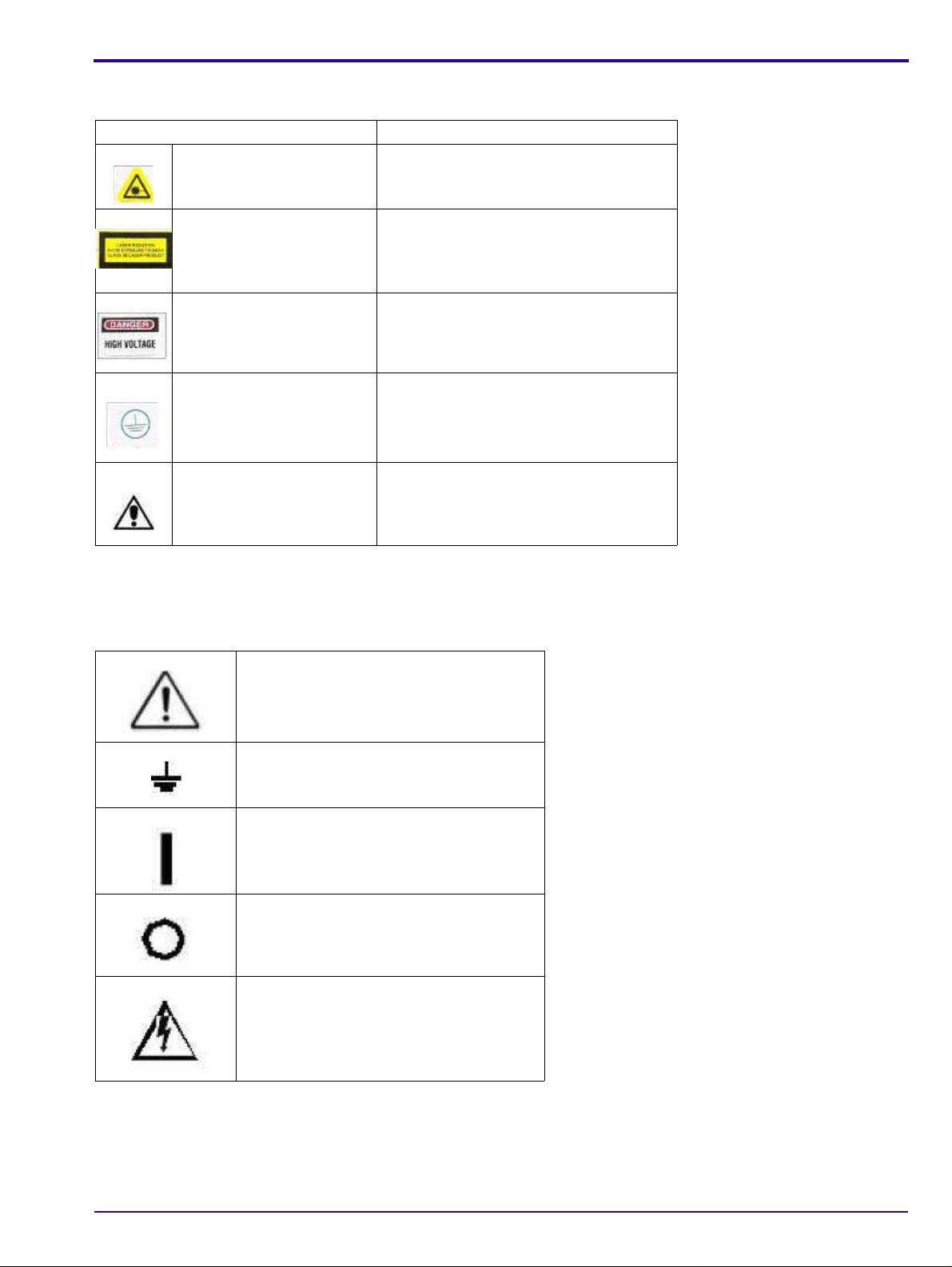
IEC Symbols Used
The system may have labels with one or more of the following symbols. These symbols indicate the IEC standards
to which the system conforms.
Warning, Caution – consult accompanying
documents
Protective ground points
Power ON
Power OFF
Caution – Electrical shock hazard
6H4866-02 13
Page 14
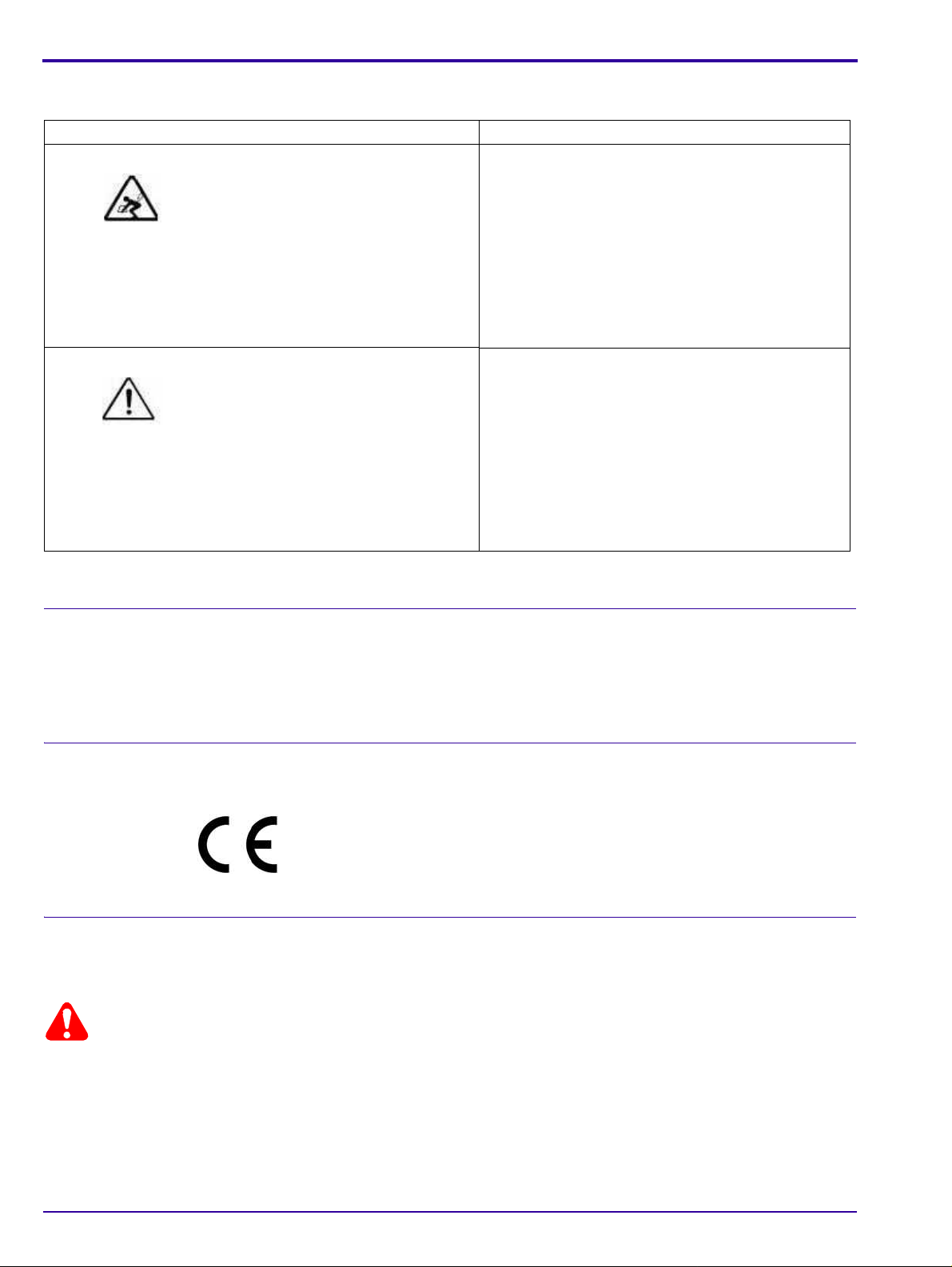
Device-specific Safety Information
Caution
Safety Information Consignes de Sécurité
LIFTING HAZARD
DANGER POIDS LOURD
The Kodak Point-of-Care 120/140
Scanner weighs 40 Kg (88lb). Do
not try to lift the Scanner by
yourself. Always seek assistance
from another person. Lifting
equipment that is too heavy may
result in injury to personnel and/or
damage to the Scanner.
WARNING
The Kodak Point-of-Care 120/140
Scanner is a CLASS 1 Laser
product.
• Do not remove the Scanner
cover.
• Cover removal shall be done
only by authorized service
personnel!
Le Scanner Kodak Point-of-Care 120/140 pèse 40
kg (88lb). N’essayez pas de porter le Scanner par
vous-même. Demandez toujours de l’aide d’une
autre personne. Porter un équipement trop lourd
peut provoquer des dommages physiques et/ou
endommager le matériel.
ATTENTION
Le Scanner Kodak Point-of-Care 120/140 est un
produit laser de la Classe 1.
• Ne pas retirer le couvercle du Scanner.
• Le retrait du couvercle doit s’effectuer
uniquement par un personnel compétent.
Regulatory Information
Introduction
This Product conforms to the following safety standards: IEC 601-1 Medical Electrical Equipment General
Requirements for Safety, EN60601-1-2 Medical Electrical Equipment Electro-Magnetic Compatibility Requirements
and Tests, IEC 60825-1 Safety of Laser Products.
This device complies with 21CFR 1040.10.
CE Conformity
This product conforms to the requirements of council directive 93/42/EEC. The Point-of-Care CR 120/140 is a Class
I medical device. The Point-of-Care CR 120/140 bears the following mark of confor mit y.
The name and address of the CE representative appears on th e back of the front page of this manual.
USA Regulations
The FDA cleared the system for sale in the USA.
Federal US law restricts this device for sale by or on the order of a physician.
14 6H4866-02
Page 15

System Description
Section 2: System Description
Introduction
Throughout this manual the Kodak Point-of-Care CR 120/140 Systems will be referred to as the
Point-of-Care CR 120/140.
The Point-of-Care CR 120/140 is designed for the reading of phosphor x-ray screens (CR) by medical professionals.
The system consists of the Point-of-Care CR 120/140 unit and the software package that includes:
•The Kodak QC software that operates the unit.
• An image viewing and archiving software package that su pports the DICOM 3.1 stand ard and was appr oved by
Carestream Health.
• The system features 8 x 10 in.; 10 x 12 in.; 14 x17 in.; 9.5 x 9.5 in. digital image reading and viewing archive.
Operational Principles
The Point-of-Care CR 120/140 is a digital imaging system for image acquisition and processing of static projection
radiography that uses a phosphor screen with energy storage capability as an x-ray image receptor.
After exposure, a laser beam, which stimulates luminescence proportional to the local x-ray exposure, reads the
screen. The luminescence signal is digitized. The data is then subjected to digital image processing.
The Point-of-Care CR 120/140 enables the user to read a screen quickly, and erase it to be ready for the next scan.
The unit is compact and easy to use.
Using the Point-of-Care CR 120/140 enables medical professionals to “go digital” without changing their work
practices or x-ray equipment.
System Overview
System Components
The Point-of-Care CR 120/140 consists of 17 major assemblies as well as sensors, which may be replaced in the
field:
USB Board Erase Lamps Assembly
Motion Board Erase Lamps Inverter Assembly
Sensor Board Sensors:
Photo Multiplier Assembly W0 Sensor
Optic Head Assembly Z0 Sensor
Roller Motor Assembly Rollers Sensor
Linear Slide Assembly Screen Size Sensors
Loader Stepper Motor Assembly R-Limit (Home) Sensor
Key Assembly and Tray Assembly L-Limit Sensor
Power Supply Assembly Loader Back Sensor
Cassette Lock Cassette Present
Auto-loop
6H4866-02 15
Page 16

Component Names and Descriptions
Part Name Description
USB Board The USB Board receives operational commands from the host PC workstation via
the USB port, and sends the commands to the appropriate Scanner component. It
also transmits image data from the Scanner to the PC.
Motion Board The Motion Board controls the Loader and Roller Motors and Erase Lamps. It reads
the scanner sensors and passes the information to the USB Board.
Linear Slide Assembly The Linear Slide Assembly moves the PM and the Optical Head Assemblies back and
forth within the Drum.
Optical Head Assembly The Optical He ad Assembly includes the Laser Module and the Rotational Motor th at
rotates the Laser Tube and a mirror during scanning. The Laser Module’s beam
illuminates the Phosphor screen and the mirror collects the light reflected from the
phosphor screen and directs it to the Photo Multiplier.
Photo Multiplier Tube
(PMT)
Key Assembly and Tray
Assembly
Power Supply The AC/DC power supply provides DC power to the Scanner components.
Loader Stepper Motor
Assembly
Roller Motor Assembly The Roller Motor Assembly pulls the phosphor screen from the cassette into the
Erase Lamps Assembly The Erase Lamps Assembly brightly illuminates the phosphor screen after scanning,
Erase Lamps Inverters
Assembly
Sensor Board The Sensor Board is a through board used to connect the sensors to the Motion
Sensors
Eraser Lamps Sensor The Erase Lamp Sensor detects an Erase Lamp failure.
Left and Right Limit
Sensors
Roller Sensor Detects when the screen enters and exits the Rollers.
W0 Sensors Top and
Bottom
Z0 Sensor Detects the presence of the screen in the Drum.
Screen Size Sensors There are four Screen Size Sensors that determine the size of the CR screen by the
15 x 30 Presence
Sensor
The Photo Multiplier (PM) Tube collects the photons emitted from the screen.
These complementary assemblies guide the cassette into the scanner and secure it
in position for the duration of the scanning process. The Auto-loop mechanism which
is attached to the Key Assembly, controls the distance that the screen is returned
into the cassette at the end of the process.
The Loader Stepper Motor Assembly extracts the phosphor screen from the cassette
in preparation for insertion into the drum and assists in inserting the screen into the
cassette.
Drum.
to erase the image so that the screen is ready to be used again.
The Erase Lamps Inverter Assembly converts the 15 VDC input to high voltage
output to power the Erase Lamps.
Board.
The Left and Right Limit Sensors indicate the end of travel of the Linear Assembly
movement.
The W0 Sensor determines the activation and deactivation of the rollers according to
screen presence at the entrance to the Drum.
location of the screen guide that is positioned by the screen as it is inserted into the
drum.
Installed in the Key Assembly, this Sensor detects the presence of a 15 x 30 in
cassette adapter.
16 6H4866-02
Page 17
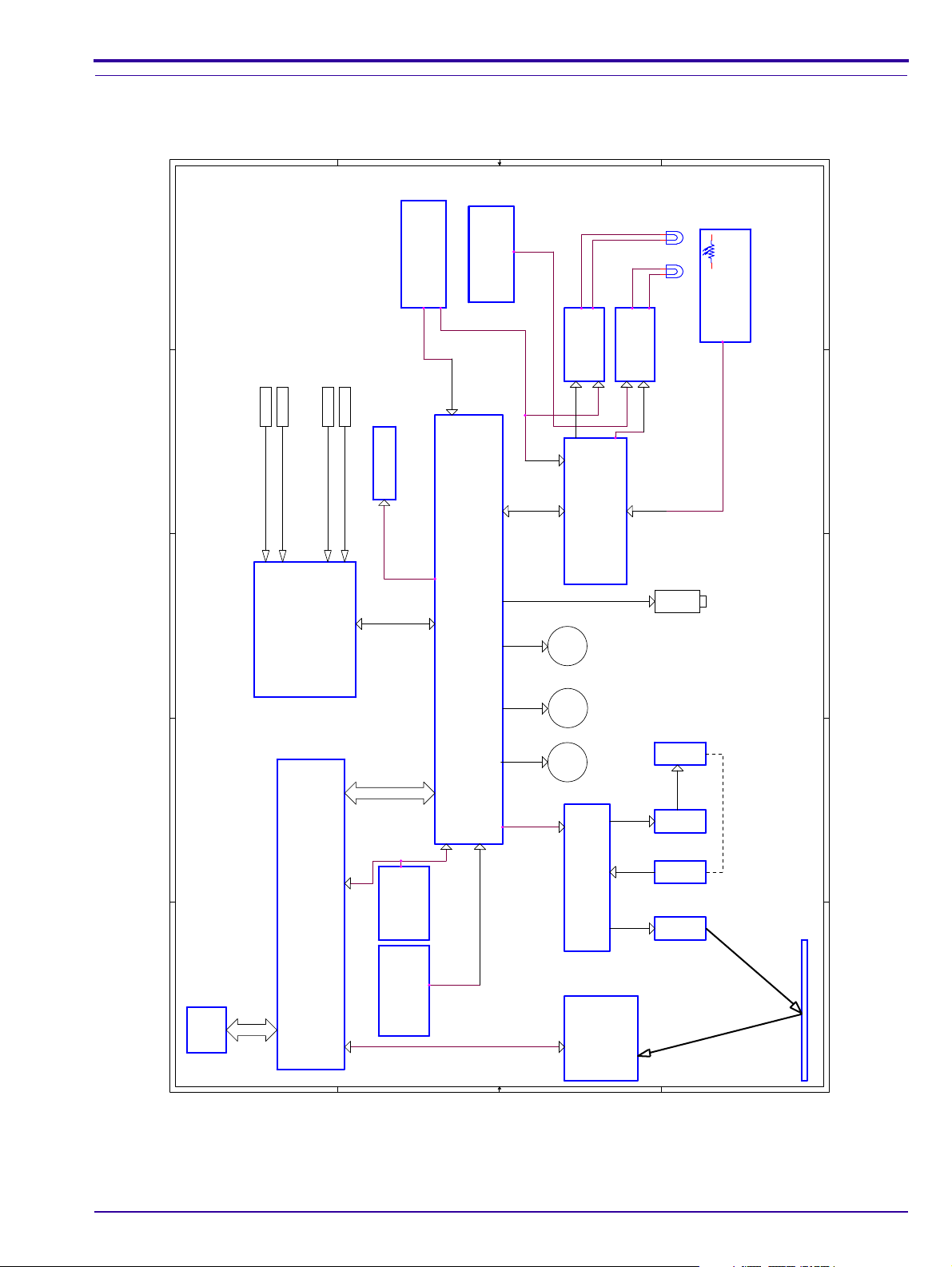
Block Diagram of PoC 120/140
1
1
2
2
3
3
4
4
5
5
A A
B B
C C
D D
J2 J4
J3
J5
J1
J500
PC
P1
USB Board
Motion Board
Sensor
Board
J501
J502
J515
J516
...
Power Supply
+5V / +12V
Power Supply
+12V
(Rotation Motor)
Carrier - Laser
PM Board
Sensor
Sensor
Sensor
Sensor
...
Power Supply
+15V
Group No. 2
Lamps Board
Inverters
Group
No. 1
Laser
Encoder
Rotation
Driver
Rotation
Motor
J300 J305 J304
U211
J213
J200
J203 J206 J204J201
J208
J211
J202
J205
J1 J401
J403
J404 J402
Roller
Motor
Load/UnloadLinear
DC
SMSM
Power Supply
+15V Lamps
(Motors+Lamps)
Group No. 1
Lamp Sensors
Board
CB090064
CB090064
Inverters
Group
No. 2
LED Panel
LAMPx8 LAMPx6
J212
Solenoid
LP9-14LP9-14LP1-8LP1-8
Block Diagram of the Point-of-Care CR 120/140
System Description
6H4866-02 17
Page 18
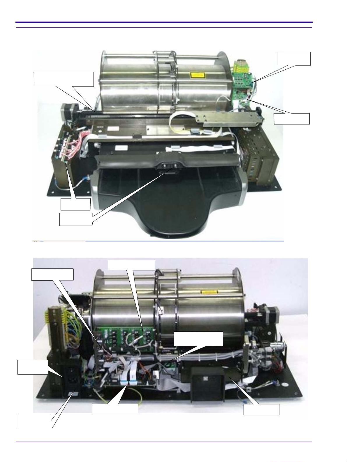
Views of PoC 120/140
LED Panel
Motor Driver
Laser Board
Inverters
Linear Slide Assembly
Sensor Board
Loader
Stepper Motor
USB Board
Motion Board
Erase Lamp
Fuses
Power Cord
Socket
On/Off
Switch
Scanner Front View
Scanner Rear View
18 6H4866-02
Page 19
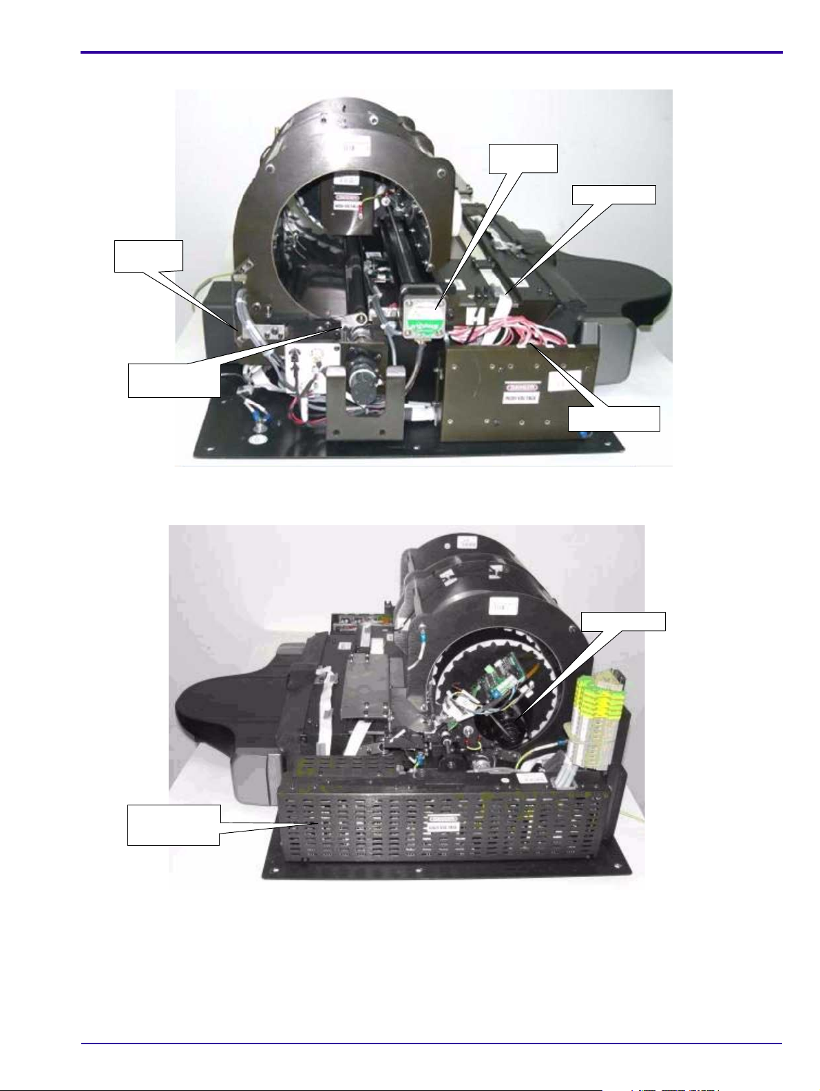
Scanner Left View
Linear
Motor
Erase Lamp
Inverters
Roller
Sensor
Roller
Motor
Laser Unit
Power Supply
Unit
System Description
Scanner Right View
6H4866-02 19
Page 20
Component Description
1
2
3
4
5
6
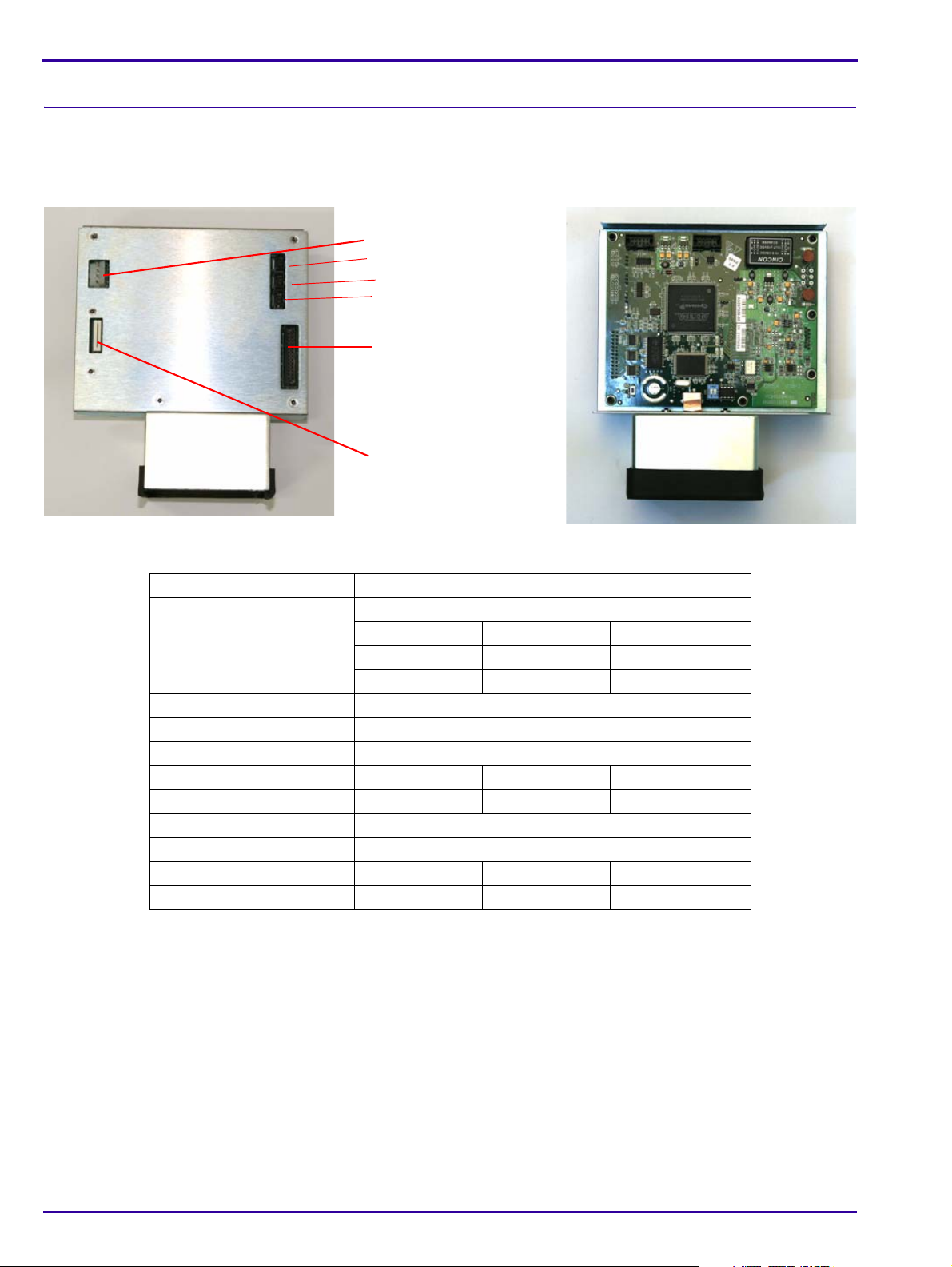
USB Board
The USB Board receives operational commands from the host PC workstation via the USB port, and sends the
commands to the appropriate Unit component. It also transmits image data from the Unit to the PC.
USB Board
USB Board Connections
Connector Destination
Connector 1 J7 5 V/12 V Power Supply
Connector 2 J3 Flat cable to J1 on PM Board
Connector 3 J1 Flex cable to J200 on Motion Board
Connector 4 J11 Barcode Connection
Connector 5 J6 Not in use
Connector 6 J4 Barcode Connection
Pin 1 White 5 V
Pin 2 Brown GND
Pin 4 Green 12 V
Pin 1 Red 5V
Pin 2 Black Gnd
Pin 1 Purple Signal
Pin 2 Brown Signal
20 6H4866-02
Page 21
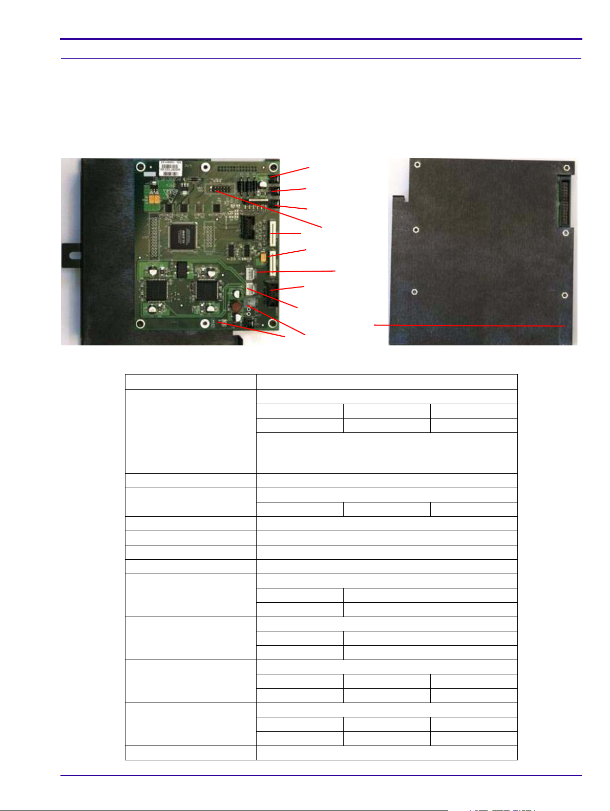
Motion Board
1
2
3
4
6
8
7
5
9
10
11
12
The Motion Board has the following functions:
• Controls the Loader and Roller Motors
• Controls the Erase Lamps
• Reads the Unit sensors and passes the information to the USB Board
Motion Board
System Description
Motion Board Connections
Connector Destination
Connector 1 J206 Connectors Panel (Rollers Motor)
Pin 1 orange 12 V
Pin 2 pink GND
Rollers forward +12 V
Rollers backwards -12 V
Rollers stop 0 V
Connector 2 J212 J212 on the Auto-loop Assemb ly
Connector 3 J213 12 V Power Supply
Pin 1 red 12 V
Connector 4 J205 J1 on Front Panel LED Board
Connector 5 J203 J401 on Laser Board
Connector 6 J208 J500 on Sensor Board
Connector 7 J202 J2 on Erase Lamps Inverters Assembly
Connector 8 J204 Loader carrier
Orange + blue 130 Hz load/unload
Red + yellow 130 Hz load/unload
Connector 9 J201 Stepper Motor
Connector 10 J211 15 V Power Supply
Connector 11 J215 5 V Power Supply
Connector 12 J302 on USB Board
6H4866-02 21
Yellow + green 11 KHz moving left/right; 0 KHz stop
Brown+ white 11 KHz moving left/right; 0 KHz stop
Pin 1 black 1 GND
Pin 2 black 2 15 V
Pin 1 brown GND
Pin 2 white 5 V
Page 22
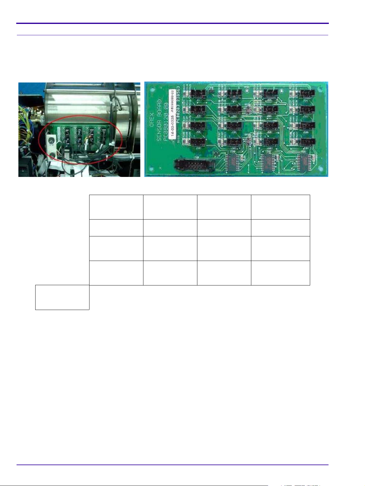
Sensor Board
Sensor Board Connections
The Sensor Board is a through board used to connect the sensors to the Motion Board.
Sensor Board
Sensor Board Connections
J500
To J208 on Motion
Board
J513
Cassette
Presence Sensor
J509
Roller Sensor
J505
Sensor 1 on the
Drum
J501
Sensor 4 on the
Drum
J514
Cassette Lock
Sensor
J510 J511
J506
Sensor 2 on the
Drum
J502
Sensor 5 on the
Drum
J515
Right Limit Sensor
W0 Sensor
J507
Sensor 3 on the
Drum
J503 J504 Auto-loop
J516
Left Limit Sensor
J512 15 x 30
Cassette Sensor
J508
Loader Sensor in
Back Position
Sensor
22 6H4866-02
Page 23
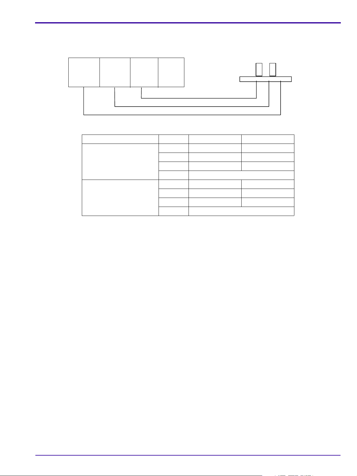
Typical Sensor Connections
1
(Brown)
5 V
2
(White)
Signal
3
(Blue)
GND
4
Not in
use
Connector
Sensor
Sensor Wiring Colors
Sensor Wire No. Wire Color Signal
Sensor On
(Flag in Sensor)
Sensor Off
(Flag not in sensor)
System Description
1 Brown 5 V always
2White 0 V
3 Blue GND always
4 Not in use
1 Brown 5 V always
2White 5 V
3 Blue GND always
4 Not in use
Measuring voltage:
1. All sensors except J511: measure between pin 2 & 3 and insert object between sensors.
2. For J511 only: measure between pin 2 & pin 3 and insert a scr een to system. The voltage shou ld be between 4.5
- 5 V.
6H4866-02 23
Page 24
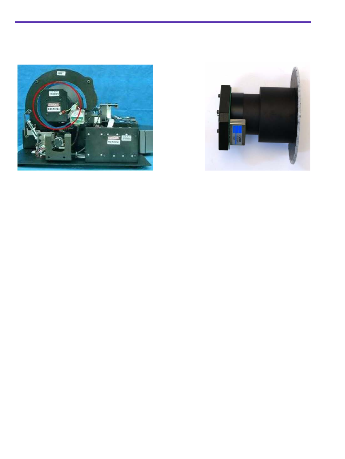
PM Assembly
The Photo Multiplier (PM) Tube collects the photons emitted from the screen.
PM and PM Board
24 6H4866-02
Page 25
System Description
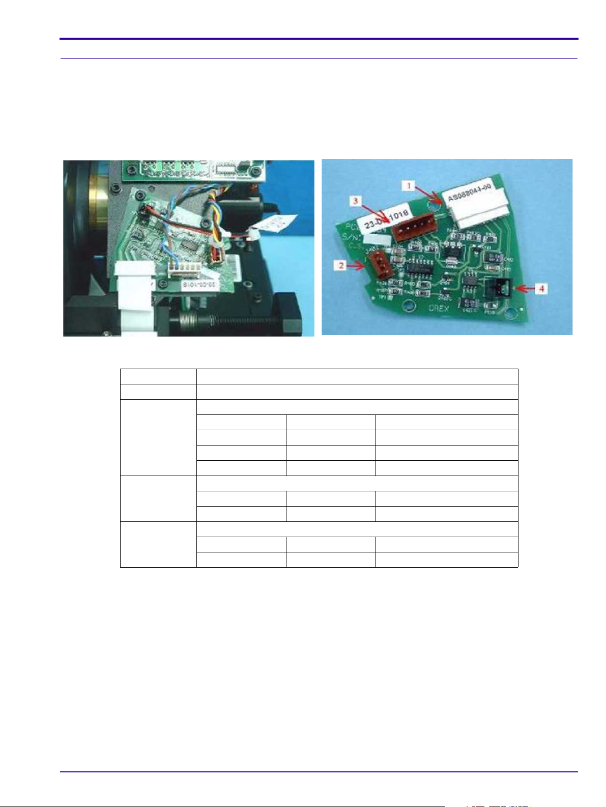
Optical Head Assembly
The Optical Head Assembly includes the Laser Module and the Rotational Motor that rotates the Laser Tube and a
mirror during scanning. The Laser Module’s beam illuminates the Phosphor screen and the mirror collects the light
reflected from the phosphor screen and directs it to the Photo Multiplier.
Laser Board
Laser Board
Laser Board Connections
Connector Destination
1 J401 on Motion Board CB080008
2 J402 Encoder Reader CB090014
Pin 1 Red GND
Pin 2 Black Index 41 ±0.5 Hz
Pin 3 Blue Encoder 41 ± 0.5 KHz
Pin 4 Yellow 5 V
3 J403 Rotation Motor Board CB090040
Pin 1 Blue GND
Pin 2 Brown 12 V Rotation Motor - On
4 J404 Laser Assembly CB090029
Pin 1 Red Laser On 3.3 V
Pin 2 Black GND
Laser Tube
The Laser Tube emits the light to energize the phosphorus screen.
6H4866-02 25
Page 26
Laser
26 6H4866-02
Page 27
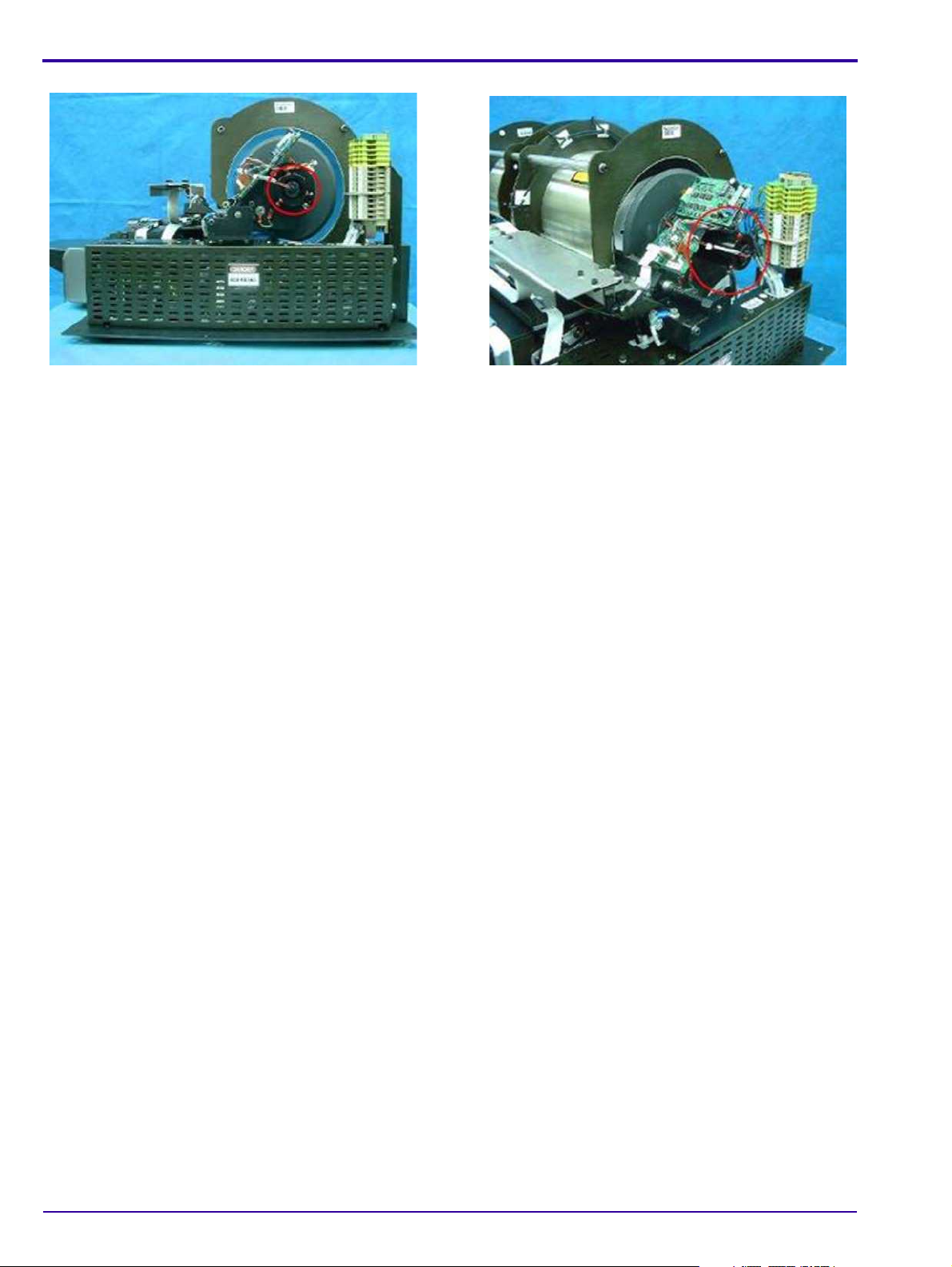
Roller Motor Assembly
Note
The Roller Motor Assembly pulls the phosphor screen from the Cassette into the Drum.
Roller Motor
Roller Motor Connector
System Description
Measure the voltage when the rollers are turning at full speed.
Roller Motor Connector
Connector Panel to the Roller Motor
Pin 1 Orange Rollers forward +15V
Rollers backwards -15 V
Rollers stop 0 V
Pin 2 Brown GND
6H4866-02 27
Page 28
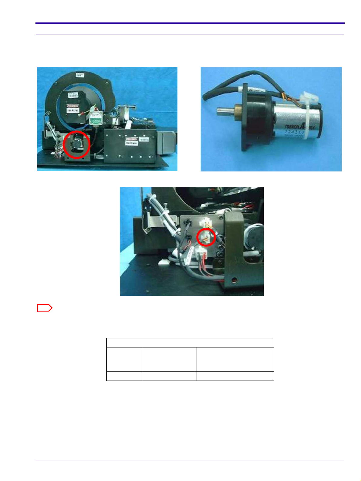
Linear Slide Assembly
The Linear Slide Assembly moves the PM and the Laser within the Drum to read the Phosphor Screen.
Linear Slide Assembly
Linear Slide Stepper Motor Connector
Slide Stepper Motor Connector
Connector Panel to the Slide Stepper Motor CB 090077
Pin 1 White Phase A
Pin 2 Orange Phase A
Pin 3 Yellow Phase B
Pin 4 Black Phase B
28 6H4866-02
Page 29
System Description
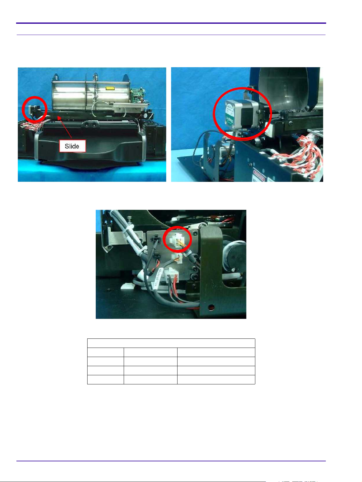
Loader Stepper Motor Assembly
The Loader Stepper Motor Assembly operates the mechanism which extracts the phosphor screen from the cassette
and assists in inserting the screen into the cassette.
Carriage Stepper Motor
Carriage Stepper Motor Wiring
Loader Stepper Motor Wiring
J204 on Motion Board
Orange + blue 130 Hz load/unload
Red + yellow 130 Hz load/unload
Black + white not in use
6H4866-02 29
Page 30
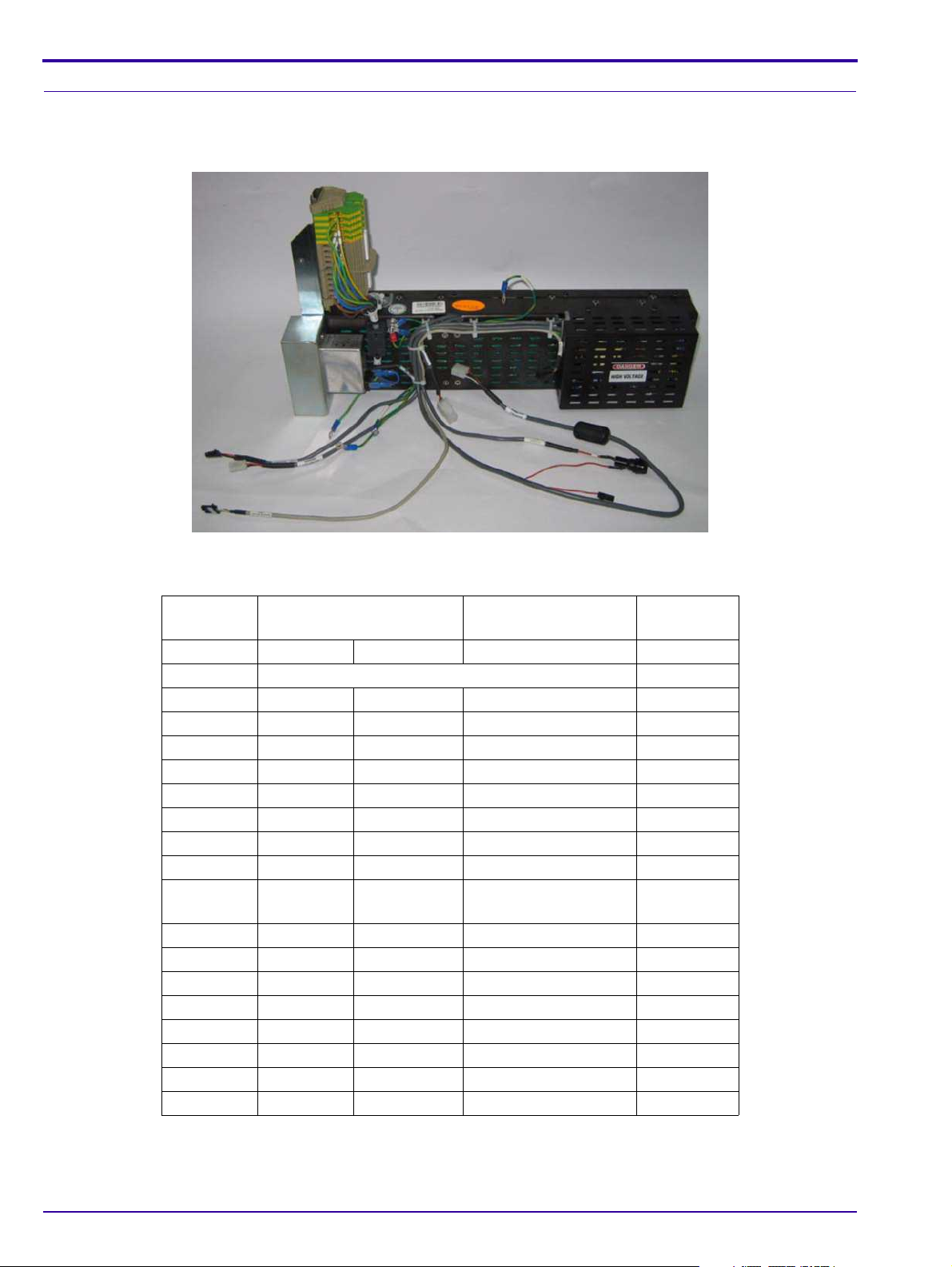
Power Supply Assembly
The AC/DC Power Supply provides DC power to the components of the unit.
Power Supply Assembly
Power Supply Connectors
Pin
Number System Type Destination Function
Pin 1 Red Black 1 15 V
Pin 2 Black 2 GND 0 V
Pin 1 Black 1 12 V
Pin 3 Red Brown 5 V
Pin 5 Black White GND 0 V
Pin 1 Red White 12 V
Pin 2 Black Brown 5 V
Pin 4 White Green GND 0 V
Pin 1 Red Black 1 15 V
Pin 2 Black Black 3 GND
Pin 3 White Black 2 15 V
Pin 4 Green Black 4 GND 0 V
ACL2/4 PoC120/140
Source: AC INPUT POWER
CB090065 CB090137 J211 on Motion Board
CB090071 CB 090141_a J213 on Motion Board
CB090064 CB090136-a J215 on Motion Board
CB090064 CB 090064_b J305 on USB Board
(power input)
CB090065 CB 090065_b Fuses Connector
30 6H4866-02
Page 31

System Description
Auto-loop Solenoid
Key Assembly
Tray Assembly
Key Assembly and Tray Assembly
These complementary assemblies guide the cassette into the sca nner and secure it in position for the duration of the
scanning process. The Auto-loop mechanism which is attached to the Key Assembly, controls the distance that the
screen is returned into the cassette at the end of the process.
Auto-loop Key Assembly and Tray Assembly
Auto-loop Key Assembly
6H4866-02 31
Page 32

Erase Lamps Assembly
3 2 4 1 3
The Erase Lamps brightly illuminate the phosphor screen to erase the image so that the screen is ready to be used
again.
Erase Lamps
Erase Lamp Assembly
Erase Lamp Voltages
Connector Destination
1 W0 Top to Connectors panel CB 090138
Pin 1 Brown 5 V
Pin 2 White GND 0 V
2 J1 CB 090140 Destination: Inverters
Pin 1 White 5 V
Pin 2 Brown Lamp on 0 V
Lamp off 2.5-5 V
Pin 3 Green Lamp on 0 V
Lamp off 2.5-5 V
Pin 4 Yellow GND
3Inverters
AC high voltage
4Not in use
32 6H4866-02
Page 33

System Description
Erase Lamps Inverter Assembly
The Inverter Assembly converts the 15 VDC input to a high voltage output to power the Erase Lamps.
Erase Lamps Inverter Assembly
Inverter Assembly Connections
Inverter Assembly Voltages
Connector Destination
1 J1 ON Lamp Sensor Board
Pin 1 White 5 V
Pin 2 Brown Lamp on 0 V
Lamp off 2.5 - 5 V
Pin 3 Green Lam p on 0 V
Lamp off 2.5 - 5 V
Pin 4 Yellow GND
2 J2 to J202 on Motion Board
3 P2 on 15 V power supply
Pin 1 Red 15 V
Pin 2 Black GND
4 AC - High voltage to Erase Lamps
6H4866-02 33
Page 34

Erase Lamp Sensor
2
1
The Erase Lamp Sensor detects an Erase Lamp failure.
Erase Lamp Sensor
Erase Lamp Sensor Connectors
Erase Lamp Sensor Voltages
1 Connected to Erase Lamp Board on the Inverter
Assembly
Pin 1 White 5 V
Pin 2 Brown Sensor 1 Lamp on 0 V
Lamp off 2.5 - 5 V
Pin 3 Green Sensor 2 Lamp on 0 V
Lamp off 2.5 - 5 V
Pin 4 Yellow Ground
2 Not in use
34 6H4866-02
Page 35

Left Limit Sensor and Right Limit Sensor
Refer to “Sensor Board Connections” on Page 22 for information on wiring connections.
Left Limit Sensor
System Description
Refer to “
Right Limit Sensor
Sensor Board Connections” on Page 22 for information on wiring connections.
6H4866-02 35
Page 36

Screen Size Sensor
There are four Screen Size Sensors that determine the size of the CR screen by the location of the screen guide that
is positioned by the screen as it is inserted into the drum.
Screen Size Sensor
Refer to “
Sensor Board Connections” on Page 22 for information on wiring connections.
36 6H4866-02
Page 37

Roller Sensor
The Roller Sensor detects when the screen enters and exits the rollers.
Roller Sensor
System Description
6H4866-02 37
Page 38

ZO Sensor
Z0 Sensor
The Z0 Sensor detects the presence of the screen in the Drum.
Refer to “
Z0 Sensor
Sensor Board” on Page 22 for information on wiring connections.
38 6H4866-02
Page 39

System Description
Top W0 Sensor
(receiver)
Bottom W0 Sensor
(transmitter)
WO Sensor
The W0 Sensor determines the activation and deactivation of the rollers according to screen presence at the
entrance to the Drum. The sensor has two parts, the Transmitter below the screen path which is accessible from the
bottom Service Panel; and the Receiver above the screen path which is inside the Drum.
Refer to “
Top WO Sensor
Sensor Board” on Page 22 for information on wiring connections.
Bottom W0 Sensor
6H4866-02 39
Page 40

Page 41

Section 3: Service Procedures
Service Tools
The following is a list of tools required for service operations:
• Phillips (cross) screwdriver (medium)
• Allen wrenches (metric): 1.5, 2, 2.5, 3, 4
•Cutters
• Long-nose pliers
• Digital voltmeter (DVM)
• ROM Chip (flash) extractor
Removing the Service Panel and Scanner Cover
Tools Required
Phillips screwdriver (medium)
Removing the Service Panel
Service Procedures
[1] Switch OFF the Unit.
[2] Remove the power cord from the Main Socket.
[3] Detach the Power Cord from the back of the Unit.
[4] Detach the USB cable.
Service Panel Screws
[5] Remove the screws securing the Service Panel on the rear of the unit, and remove the Service Panel.
6H4866-02 41
Page 42

Removing the Scanner Cover
Laser Warning
Caution
Do not operate the unit while the laser is connected without proper eye protection. Safety glasses, (see “Laser Safety
Instructions” on Page 12) must be worn by all personnel in the area of the unit! Authorized personnel only may
remove the cover. Before operating the unit without the cover, disconnect the lase r. (See “
on Page 44.)
[1] Pull the scanner to the edge of the t able so tha t one side is exten ded over the t able edge to gai n access to the
cover screws on that side and remove them.
[2] Pull the scanner to another side of the table, and remove the screws on that side; and so on, until all fourteen
screws are removed.
To remove screws from the bottom of the unit, do not turn it on its back. Move the unit to the edge of the worktable
to gain access from below.
Access to Cover Screws
Disconnecting the Laser”
Cover Screws
[3] Lift the cover off.
42 6H4866-02
Page 43

Reinstalling the Scanner Cover and Service Panel
[1] Reverse the above steps to reinstall the cover.
Service Procedures
6H4866-02 43
Page 44

Disconnecting the Laser
Important
The Laser must be disconnected befo re per fo rm in g an y pr oc ed ures that do not demand a functioning las er duri ng
servicing.
[1] Remove the Main Cover, (see See “
Laser Connector on the Laser Board
Removing the Service Panel and Scanner Cover” on Page 41.).
[2] Disconnect the Laser Connector from the Laser Board. Depress the latch of the connector firmly to release it.
[3] Reconnect the Laser only after all repairs are complete.
[4] Reinstall the Main Cover.
44 6H4866-02
Page 45

Replacing the Fuses
Pry out gently from
this plastic tab.
Tools Required
• Flat screwdriver
• Replacement fuse
Procedure
[1] Switch OFF the power and remove the power connector from the system.
[2] Locate the Fuse Drawer on the power inlet module.
Location of Fuses
Service Procedures
[3] Open the drawer using flat screw driver, prying gently from the plastic tab.
[4] Remove the blown fuse and replace it with a new one.
[5] Close the Fuse Drawer.
[6] Turn on the system and verify that it functions properly.
6H4866-02 45
Page 46

Power Inlet Module Replacement
Laser Warning
Important
Tools Required
• 5.5 mm Socket wrench
• 7.0 mm Socket wrench
• 2.5 x 75 mm flat screwdriver
Procedure
To avoid possible eye damage, before performing this procedure di sconnect the Laser as described in “Laser Board
Replacement” on Page 54. For additional laser precautions see “Disconnecting the Laser” on Page 44.
Before performing this procedure:
• Switch off the Scanner.
• Remove the power cord from the main socket.
• Detach the Power Cord from the back of the Scanner.
[1] Remove the Back Panel and the Main Cover (See “
Page 41.)
Removing the Service Panel and Scanner Cover” on
Nuts Securing the Module
[2] Open:
• Nuts on the side of the module
• Nut on the ground stud and remove the Line Filter Wire from the stud. Do not try to detach it from the Power
Module. (See Figure “
Nuts Securing the Module” on Page 46.)
46 6H4866-02
Page 47

Line Filter Wire Attached to Ground
Power Inlet
Module
[3] Disconnect the black numbered wires from the line filter on the input module.
[4] Remove the module and install the new one.
Side View of Power Module Showing Connection Tabs
Service Procedures
[5] Connect:
• Black numbered wires to the connection tabs of the new module.
• Yellow ground wire to the ground stud and tighten the nut
[6] Secure the input module to its location with the two nuts.
[7] Close the covers.
[8] Connect the system to the main power and confirm that the system is operating properly.
6H4866-02 47
Page 48

USB Board Replacement
Tools Required
2.0 mm Allen wrench
Removing the USB Board
[1] Disconnect the Scanner from the main power.
[2] Remove the Service Panel (see “
USB Cover
Removing the Service Panel and Scanner Cover” on Page 41).
[3] Remove the 2 USB cover screws.
USB Board Connectors
[4] Pull the USB Board out and disconnect the cables from the bottom of the board.
[5] Slide the USB Board out of the scanner.
Replacing the USB Board
[1] Slide the USB Board into the scanner.
[2] Reconnect the connectors.
[3] Insert the USB cover and fasten the USB cover screws.
[4] Perform the test procedures in the section below before assembling the Scanner Cover.
48 6H4866-02
Page 49

Service Procedures
Laser Warning
[5] Assemble the Service Panel.
[6] Perform calibration as outlined in “
Calibrations” on Page 10 7.
Test Procedure
When a service operation is taking place with the cover removed, disconnect the Laser according to the procedure
in “
Laser Board Replacement” on Page 54. If the Laser must be activated during the servic e procedure, wear
protective safety glasses at all times.
[1] Confirm that the USB Board functions by performing the following test:
(a) Make sure that the computer recognizes that a USB device has been connected. The USB device icon
should appear in the system tray in the lower right corner of the screen.
(b) Perform:
• Scan without the cover in place. The preview imag e sh ou ld be bla ck.
• Scan with the cover in place, without tightening the screws. The preview image should be white.
(c) Tighten the screws.
(d) Perform a scan with an actual image and check image quality and position.
(e) Open the “About” screen in Setup, and check that the version number of the hardware and software are
correct.
6H4866-02 49
Page 50

Motion Board Replacement
Tools Required
2.0 mm Allen wrench
Removing the Motion Board
[1] Disconnect the Scanner from the main power.
[2] Remove the service panel (see See “
Motion Board Bracket Screws
Removing the Service Panel and Scanner Cover” on Page 41.).
[3] Remove the two 2.5 mm Allen screws securing the Motion Board bracket and pull the Motion Board forward
Motion Board Connectors
[4] Disconnect the cables from the Motion Board.
Replacing the Motion Board
[1] Slide the Motion Board into the scanner housing.
[2] Reconnect the connectors to the Motion Board.
[3] Insert the two Motion Board retaining screws.
[4] Assemble the Service Cover.
Test Procedure
[1] Verify that the Motion Board functions properly by operating the system.
50 6H4866-02
Page 51

Service Procedures
Note
Sensor Board Replacement
Tools Required
2 mm Allen wrench
Removing the Sensor Board
[1] Remove the Service Panel (see See “Removing the Service Panel and Scanner Cover” on Page 41.).
Sensor Board Connections
[2] Remove the electrical connectors from the Sensor Board.
Sensor Board Screws
[3] Remove the four 2.5 mm Allen screws securing the Sensor Board.
Replacing the Sensor Board
[1] Insert the four Sensor Board retaining screws.
[2] Insert the connectors to the Sensor Board.
Each connector is marked with a number to indicate its location.
[3] Assemble the Service Cover.
Test Procedure
[1] Verify that the Motion Board functions properly by operating the system.
6H4866-02 51
Page 52

PM Tube and PM Board Replacement
Laser Warning
Tools Required
3.5 mm Allen wrench
Removing the PM Tube
To avoid possible eye damage, be fore operating the unit witho ut the cover, disconnect the laser (see “Disconnecting
the Laser” on Page 44). For additional laser precautions see “Laser Safety Instructions” o n Page 12. Only authorized
personnel may remove the cover.
[1] In the Diagnostic tab and move the optical head to the left position.
[2] Remove the scanner Main Cover (see “
PM Ground Wire
Removing the Service Panel and Scanner Cover” on Page 41).
[3] Disconnect the 3.0 mm Ground wire connector to the Slide body from the PM Tube.
Connector to the PM Board
[4] Disconnect the flex cable from its connector at the bottom of the PM Board.
52 6H4866-02
Page 53

Service Procedures
Note
PM Assembly Screw (one side shown)
[5] Remove the 4.0 mm retaining screws securing the PM Assembly to the bracket.
[6] Remove the PM Tube.
PM Assembly Lower Screw
Replacing the PM Tube
Bracket retaining screws: There are two sizes of screw; the right-side screw is long, and the bottom screw is short.
[1] Insert the short 4.0 mm Bottom Bracket retaining screw, but do not tighten it yet.
[2] Insert and leave loose the long 4.0 mm right-side bracket retaining screw.
[3] Push the PM Tube forward towards the Drum until the screws line up with the holes, and tighten the retaining
screws.
[4] Reconnect the Blue Ribbon USB Connector to the bottom of the PM Tube.
[5] Insert the Blue Ribbon USB Cable into the plastic clip on the PM Tube.
[6] Reconnect the 3.0 mm ground wire connector to the Slide body.
[7] Test Procedure (1): perform a scan, and make sure that the image is completely black with the cover off.
[8] Assemble:
• Scanner Cover
• Service Panel
[9] Test Procedure(2): perform a scan, and make sure that the image is completely white with the cover in place.
[10] Test Procedure (3): perform an Offset Calibration as outlined in “
sure you get a “Calibration successfully completed” message.
Nominal Calibration” on Page 107 and make
6H4866-02 53
Page 54

Laser Board Replacement
Laser Warning
Tools Required
2.5 mm Allen wrench
To avoid possible eye damage, be fore operating the unit witho ut the cover, disconnect the laser (see “Disconnecting
the Laser” on Page 44). For additional laser precautions see “Laser Safety Instructions” o n Page 12. Only authorized
personnel may remove the cover.
Removing the Laser Board
[1] Disconnect the Scanner from the main power.
[2] Remove the Main Cover (see “
Laser Board Connectors
Removing the Service Panel and Scanner Cover” on Page 41).
[3] Disconnect the cables from the Laser Board.
Laser Board Screws
[4] Remove the three3.0 mm Allen screws securing the Laser Board, and remove the board.
54 6H4866-02
Page 55

Service Procedures
Laser Warning
Replacing the Laser Board
[1] Insert the three 3.0 mm retaining screws.
[2] Reconnect the cables to the Laser Board.
[3] Perform the test procedures in the section below, before replacing the Scanner Cover.
[4] Assemble:
• Scanner Cover
• Service Panel
Test Procedure
If the Laser must be activated during the service procedure, wear protective safety glasses at all times.
[1] Confirm that the Laser tube functions by the following test:
(a) Check that the red line on the tube is in line with the red sign on the Rotation Motor Bracket
(b) Log in to Technician mode.
(c) Click the “Diagnostics” tab in “Setup.”
(d) Perform a scan with the Cover open. Make sure that the Laser unit is functioning properly and that a
steady beam is produced.
[2] Perform the following test to confirm that the board is functioning properly.
(a) Login in Technician mode.
(b) Click the “Diagnostics” tab in Setup.
Laser Operation
(c) Activate:
• Laser unit by clicking [On] (See Figure “
• Rotational motor by clicking [On]
(d) Make sure that the value 40±0.5 appears in the speed window.
Laser Operation” on Page 55.)
6H4866-02 55
Page 56

Roller Motor Replacement
Tools Required
1.5 mm Allen wrench
2.5 mm Allen wrench
Cutter
2.5 mm x 100 mm plastic ties
Removing the Roller Motor
[1] Disconnect the Scanner from the main power.
[2] Remove the Service Panel and Scanner Cover. (see “
Page 41).
[3] Cut the plastic cable ties tying the Roller Motor cable.
[4] Disconnect the white Roller Motor Connector from the Connector Panel.
Roller Motor Connector
Removing the Service Panel and Scanner Cover” on
[5] Remove the four 2 mm screws from the base of the Roller Motor and pull back the Roller Motor.
Roller Motor Screws
56 6H4866-02
Page 57

[6] Remove the Drive Adaptor from between the Motor Drive and the Roller Drive.
Roller Driver
Drive Adapter
Motor Drive Retaining
Screw
alignment
channel
Roller Motor Drive retaining screw
Service Procedures
[7] Loosen the 3.0 mm retaining screw on the Motor Drive, and pull the Roller Motor out from the Motor Drive.
Replacing the Roller Motor
Roller Motor Drive
[1] Insert:
• Roller Motor into the Motor Bracket
Drive Adaptor
• Motor Drive into the Roller Motor completely, and tighten the 3.0 mm retaining screw
[2] Place the Drive Adaptor on to the Roller Drive.
[3] Align the Roller Drive, the Adaptor, and the Motor Drive, by turn ing the Roller Drive.
6H4866-02 57
Page 58

[4] Attach the top 2.00 mm Roller Motor retaining screw in to the top of the bracket.
[5] Realign the Roller Drive, and insert the remaining three 2.00 mm Motor ret aining scre ws and tighten them into
place.
[6] Reconnect the Roller Motor Cable to the Connector Panel, and fasten the cable ties.
[7] Perform the test procedure in the section before replacing the Scanner Cover.
[8] Assemble:
• Scanner Cover
• Service Panel
Test Procedure
Operating the Roller Motor
[1] Confirm that the Roller Motor functions by the following test:
(a) Go to the Kodak QC diagnostic screen and operate the rollers forward and backward.
(b) Load a Cassette into the Scanner and check that the Scanner loads and unloads the screen correctly.
58 6H4866-02
Page 59

Linear Slide Assembly Replacement
Tools Required
Allen wrench
Removing the Linear Slide Assembly
[1] Using the user interface Diagnostic tab, move the Optical Head to the middle of the drum.
[2] Remove the main cover (see “
Connector to USB Board
Removing the Service Panel and Scanner Cover” on Page 41).
Service Procedures
[3] Disconnect the flex cable from the USB Board.
Laser Board Cable and Connectors
[4] Disconnect the Laser Board flex cable from the Motion Board.
[5] Release the two flex cables, until they can be taken out freely along with the Slide Assembly.
6H4866-02 59
Page 60

Stepper Motor and Left Limit Sensor Connectors
[6] Disconnect the Slide Stepper Motor Cable and the Left Limit Sensor Cable from the Connector Panel.
Right Limit Sensor Connector
[7] Disconnect the Right Limit Sensor Cable from its connecto r and remove the connector from its bracket
Screw Attaching the Ground Wire
60 6H4866-02
Page 61

Service Procedures
[8] Disconnect the ground wire from the slide, by removing the screw; then, removing the ground wire.
Slide Assembly Attaching Screws
[9] Remove the four screws holding the Slide Assembly to the system (two on each side).
[10] Remove the Slide Assembly from the system by pulling it to the left, until it is out of the drum. While pulling it
out, pay attention to the location of the flex cables.
Slide Assembly
Replacing the Slide Assembly
[1] Insert the new Slide Assembly into the drum from the left.
[2] Install the four screws that hold the Slide Assembly to the system.
[3] Attach the ground wire to the Slide.
[4] Attach:
Right Limit Sensor
Left Limit Sensor
Slide Stepper Motor cable
Laser Board flex cable
USB board flex cable
[5] Insert the flex cables into their holder brackets.
[6] Perform the following test procedure before replacing the Scanner Cover.
(a) Go to the “Diagnostics” tab.
6H4866-02 61
Page 62

Linear Slide Test
(b) Click the left and right arrows to move the slide from side to side.
(c) Check that the optical head moves smoothly and that the wires are not stuck during movement.
[7] Assemble the Scanner Cover and Service Panel.
62 6H4866-02
Page 63

Loader Stepper Motor Replacement
Tools Required
3.0 mm Allen wrench
2.5 x 100 mm cable ties
Cutter
Removing the Loader Stepper Motor Carriage
[1] Using the user interface “Diagnostic” screen, move the Optical Head to the middle of the drum.
[2] Remove the Main Cover (see “
Connector J505 on the Connector Board
Removing the Service Panel and Scanner Cover” on Page 41).
Service Procedures
[3] Disconnect connector J505 on the Sensors Board; making sure that the wire is free.
Stepper Motor Cable
[4] Disconnect the Stepper Motor Cable from the Motion Board J204 (Loader) connector.
6H4866-02 63
Page 64

Bottom of Unit
[5] Place the unit on its back, and open the door on the bottom.
Pulling the Carriage Down
[6] Pull the Carriage down.
Carriage Assembly Attaching Screws
[7] Remove the four screws attaching the Carriage Assembly to the system, and pull the Carriage Assembly out.
64 6H4866-02
Page 65

Loader Assembly with Stepper Motor
4 Attaching Screws (M3)
Stepper Motor
Frame
Coupling Screw
Service Procedures
[8] Loosen the coupling screw closest to the motor.
[9] Remove the four screws that attach the motor to the loader asse mbly.
[10] Carefully remove the motor from the assembly.
Replacing the Stepper Motor
[1] Attach the Stepper Motor to the Carriage, connect the 4 M3 attaching screws and the coupling screw.
[2] Attach:
• Stepper Motor unit into the Motor Frame
• Four 3.0 mm screws
• Sensor Cable
• Motion Board Cable
[3] Close the Bottom Service Access Panel and return the Scanner on to its base.
[4] Reconnect the Sensor Cable to the Sensor Board and the Motion Cable to the Motion Board and fasten the
cable ties.
[5] Perform the test procedures in “
Scanner Cover.
[6] Attach:
• Scanner Cover
• Service Panel
Loader Pin and Loader Pusher Adjustments” on Page 132 before replacing the
6H4866-02 65
Page 66

Power Supply Assembly Replacement
Laser Warning
Ground Wire
Power Connector
Power Input Module
Ground Wires
Terminal Connectors
Introduction
When a service operation is taking place with the cover removed, disconnect the Laser according to the procedure
in “
Laser Board Replacement” on Page 54. If the Laser must be activated during the service procedure, wear
protective safety glasses at all times.
The Power Supply Assembly distributes and converts main electricity to the Scanner.
Power Supply Assembly
Tools Required
Replacement Power Supply Assembly
3.0 mm Allen wrench
7 mm spanner
2.5 x 100 mm cable ties
Cutter
Removing the Power Supply Unit
[1] Disconnect the Scanner from the main power.
[2] Disconnect the main supply cable from the Power Supply.
[3] Remove the Main Cover (see “
66 6H4866-02
Removing the Service Panel and Scanner Cover” on Page 41).
Page 67

Service Procedures
Power Supply Screws on Unit Bottom
[4] Pull the system to the edge of the table, and open the six screws th at attach the Power Supply assembly to the
base of the unit.
Cable Connection to USB Board
[5] Disconnect the power cable from the USB Board.
6H4866-02 67
Page 68

Connectors on the Motion Board
J211
J215
J213
[6] Disconnect connectors J211, J213 and J215 from the Motion Board.
Ground Wire Screw
[7] Remove the 3.5 mm screw which attaches the ground wire to the slide.
68 6H4866-02
Page 69

Main Ground Stud
[8] Remove from the stud:
• 7 mm nut
• main ground wires
Service Procedures
Fuse Connector
[9] Disconnect the fuse connector.
[10] Remove the power supply assembly.
Replacing the Power Supply Assembly
[1] Connect the fuse connector to the new Power Supply assembly.
[2] Install the Power Supply assembly and insert the six screws that attach the Power Supply assembly to the base
of the unit.
[3] Install the main ground wires and the 7 mm nut onto the stud.
[4] Install the 3.5 mm Allen screw attaching the ground wire to the slide.
[5] Connect connectors J213, J211 and U211 to the Motion Board.
[6] Disconnect the power cable from the USB Board.
[7] Perform this Test Procedure: Connect the system to the main power and confirm that the system is operating
properly.
[8] Close the Scanner Cover.
6H4866-02 69
Page 70

Erase Lamps Assembly Replacement
Laser Warning
To avoid possible eye damage, be fore operating the unit witho ut the cover, disconnect the laser (see “Disconnecting
the Laser” on Page 44). For additional laser precautions see “Laser Safety Instructions” o n Page 12. Only authorized
personnel may remove the cover.
[1] Remove the Main Cover (see “
[2] Remove the Slide (see “
Erase Lamp Connectors
Removing the Service Panel and Scanner Cover” on Page 41).
Linear Slide Assembly Replacement” on Page 59).
[3] Disconnect the Lamp Cables from the Inverters.
Erase Lamp Sensor Connector
[4] Disconnect the Erase Lamp Sensor Cable from the Inverter Assembly.
70 6H4866-02
Page 71

Service Procedures
W0 Upper Sensor Cable Connector
[5] Disconnect the W0 Upper Sensor Cable from the Connector Panel, and re move the conn ector fro m the p an el.
Erase Lamp Assembly Screws
[6] Remove the three screws that attach the Erase Lamp Assembly, two on the left side, one on the right side.
6H4866-02 71
Page 72

Erase Lamp Assembly Wiring Harness
[7] Remove the Erase Lamps Assembly through the drum front opening. The Erase Lamp Assembly includes all
the wiring, as shown in the image above.
[8] Reverse the above steps to install the Erase Lamp Assembly.
72 6H4866-02
Page 73

Erase Lamps Inverters Replacement
Tools Required
Allen wrench
Removing the Erase Lamps Inverters
[1] Remove the Main Cover (see “Removing the Service Panel and Scanner Cover” on Page 41).
Inverter Cover Screws
Service Procedures
[2] Remove the four screws securing the Inverter Cover.
Erase Lamp Connectors
[3] Disconnect the Erase Lamps Connectors from the Inverters.
[4] Disconnect the cables from the Erase Lamp Board.
6H4866-02 73
Page 74

Inverter Attaching Screws
Laser Warning
[5] On the bottom of the unit, remove the screws that attach to the Inverter Assembly.
[6] Remove the Inverter Assembly.
Replacing the Erase Lamps Inverters Assembly
[1] Insert the Erase Lamps Inverter Assembly.
[2] On the bottom of the unit, insert the screws that attach the Inverter Assembly.
[3] Connect the cables to the Erase Lamp board.
[4] Connect the Erase Lamp Connectors to the Inverte r s.
[5] Install the Inverter Cover and insert the four retaining screws.
When a service operation is taking place with the cover removed, disconnect the Laser according to the procedure
in “
Laser Board Replacement” on Page 54. If the Laser must be activated during the service procedure, wear
protective safety glasses at all times.
[6] Perform the following Test Procedure:
Log in as technician and in the Diagnostic screen check that the Erase Lamps are on and that the Indicator
Lamps are on.
Checking the Erase Lamps
[7] Close the Scanner Cover.
74 6H4866-02
Page 75

Erase Lamps Sensors Replacement
Tools Required
Allen wrench
Removing the Erase Lamps Sensors
[1] Remove the Main Cover (see “Removing the Service Panel and Scanner Cover” on Page 41).
Flex Cable Bracket
Service Procedures
[2] Open the five screws that attach the Flex Cable Bracket to the system.
Erase Lamp Sensor
[3] Disconnect the cable from the Erase Lamp Sensor.
6H4866-02 75
Page 76

Erase Lamp Sensor Screws
Laser Warning
[4] Remove the two screws securing each of the sensors, and remove the sensor(s).
Replacing the Erase Lamps Sensors
[1] Insert the sensors and the screws securing the sensors.
[2] Connect the cable from the Erase Lamp Sensor.
[3] Insert the five screws that attach the Flex Cable Bracket to the system.
When a service operation is taking place with the cover removed, disconnect the Laser according to the procedure
in “
Laser Board Replacement” on Page 54. If the Laser must be activated during the service procedure, wear
protective safety glasses at all times.
[4] Perform the following Test Procedure:
Log in as technician and in the Diagnostic screen check that the Erase Lamps are on and that the Indicator
Lamps are on.
Checking the Erase Lamps
[5] Close the Scanner Cover.
76 6H4866-02
Page 77

Left Limit Sensor Replacement
Tools Required
3.0 mm Allen wrench
2.5 x 100 mm cable ties
Cutter
Removing the Left Limit Sensor
[1] Disconnect he Scanner from the main power.
[2] Remove the Main Cover (see “
Left Limit Sensor Connector
Removing the Service Panel and Scanner Cover” on Page 41).
Service Procedures
[3] Disconnect the Sensor Cable from the Connector Panel.
[4] Mark the location of the sensor.
Left Limit Sensor Screws
[5] Remove the two screws attaching the sensor to the sensor bracket, and remove the sensor.
Replacing the Left Limit Sensor
[1] Position the sensor bracket according to the marked location and insert the two screws.
[2] Connect the Sensor Cable to the Connector Panel.
6H4866-02 77
Page 78

[3] Confirm that the Left Limit Sensor functions by performing the following test:
Indicator
Light
Indicator
Light
(a) Enter the Diagnostic screen in the Kodak QC PoC 140.
(b) In the Linear Motor section, click the right or left arrow according to the limit switch you wish to test.
(c) The Carrier begins to move, and should enter the sensor area causing the indicator light to illuminate.
Linear Motor Section of Diagnostics Screen
[4] Assemble the scanner cover.
78 6H4866-02
Page 79

Right Limit Sensor Replacement
Indicator
Light
Indicator
Light
Tools Required
3.0 mm Allen wrench
2.5 x 100 mm cable ties
Cutter
Removing the Right Limit Sensor
[1] Disconnect the system from the main power.
[2] Remove the Main Cover (see “
[3] Move the Optical Head a few centimeters to the left.
Right Limit Sensor
Removing the Service Panel and Scanner Cover” on Page 41).
Service Procedures
[4] Mark the position of the sensor on the sensor bracket.
[5] Disconnect the cable from the connector on the sensor bracket, open two 2.0 mm Allen screws, and remove
the sensor.
Replacing the Right Limit Sensor
[1] Position the sensor bracket according to the marked location and insert the two screws.
[2] Connect the Sensor Cable to the Connector Panel.
[3] Confirm that the Right Limit Sensor function s by per for m ing the follo wing tes t:
(a) Enter the Diagnostic screen in the Kodak QC PoC 140.
(b) In the Linear Motor section, click the right or left arrow according to the limit switch you wish to test.
(c) The Carrier begins to move, and should enter the sensor area causing the indicator light to illuminate.
Linear Motor Section of Diagnostics Screen
[4] Assemble the scanner cover.
6H4866-02 79
Page 80

Screen Size Sensor Replacement
Tools Required
3.0 mm Allen wrench
2.5 x 100 mm cable ties
Cutter
Removing the Screen Size Sensor
[1] Disconnect the Scanner from the main power.
[2] Remove the main cover (see “
Screen Size Sensor (1 of 4)
Removing the Service Panel and Scanner Cover” on Page41).
[3] Locate the Sensor and remove the two Allen screws.
[4] Cut the wire ties holding the sensor cable, and follow the cable up to the sensor board.
[5] Disconnect the cable from the Sensor board.
Installing the Screen Guide Sensor
[1] Connect the Screen Guide Sensor to the Sensor board.
[2] Install the Sensor cable using new cable ties.
[3] Install the Sensor to the Sensor bracket using the two Allen screws.
[4] Perform the following two tests:.
Screen Guide Passing Under Screen Size Sensor
80 6H4866-02
Page 81

Service Procedures
Screen Guide
(a) Make sure that the Screen Guide passes under the sensor without interference.
(b) Open the “Diagnostics” screen in the Kodak QC. Move the Screen Guide up and down and check that the
Z0 light in the “Diagnostics” screen turns on and off.
Z0 Light
Screen Guide
[5] Assemble:
• Scanner Cover
• Service Panel
6H4866-02 81
Page 82

Roller Sensor Replacement
Introduction
The Roller Sensor senses when the screen is between the rollers.
• Replacement Sensors
• 1.5 mm Allen wrench
• 2.5 x 100 mm cable ties
• Cutter
Removing the Roller Sensor
[1] Disconnect the Scanner from the main power.
[2] Remove the main cover (see “
Roller Sensor
Removing the Service Panel and Scanner Cover” on Page41).
[3] Mark the position of the sensor.
[4] Remove the two screws securing the sensor, and remove the sensor.
[5] Disconnect the sensor cable J509 from the Sensor board.
Replacing the Roller Sensor
[1] Install the roller sensor, using the marked location of the previous sensor, and insert the two retaining screws.
[2] Connect the sensor cable J509 to the Sensor board.
[3] Continue to “
[4] Install the Scanner Main Cover.
Roller Sensor Adjustment” on Page 135 to verify correct positioning of the Roller Sensor.
82 6H4866-02
Page 83

Z0 Sensor Replacement
Z0 Sensor
Procedure
[1] Disconnect the Scanner from the main power.
[2] Remove the Service Panel and Scanner Cover. (See “
Page 41.)
Z0 Sensor
Service Procedures
Removing the Service Panel and Scanner Cover” on
[3] Reveal the Z0 Sensor on the back of the Drum.
[4] Disconnect the cable from the Sensors Board (J505).
[5] Remove the two 2.0 mm retaining screws from the sensor, and remove the Sensor from the Slide.
[6] Attach the Z0 Sensor on the back of the Drum, and loosely insert the two 2.0 mm retaining screws.
[7] Slide the Sensor up or down till the screen is in the middle of the bracket.
[8] Reconnect the Sensor Connector to J505 on the Sensor Board.
[9] Perform the test procedures in the section below, before replacing the Scanner Cover.
[10] Assemble:
• Scanner Cover
• Service Panel
6H4866-02 83
Page 84

Test Procedure
Laser Warning
Screen Guide
When a service operation is taking place with the cover removed, disconnect the Laser according to the procedure
in “
Laser Board Replacement” on Page 54. If the Laser must be activated during the service procedure, wear
protective safety glasses at all times.
Z0 Light
[1] Open the “Diagnostics” screen in the Kodak QC.
Screen Guide
[2] Move the Screen Guide up and down and check that the Z0 light in the “Diagnostics” screen turns on and off.
84 6H4866-02
Page 85

Service Procedures
Laser Warning
W0 Sensor
PM moved to
the right of the Drum
W0 Sensors Replacement (Top/Receiver and Bottom/Transmitter)
Introduction
When a service operation is taking place with the cover removed, disconnect the Laser according to the procedure
in “
Laser Board Replacement” on Page 54. If the Laser must be activated during the servic e procedure, wear
protective safety glasses at all times.
Top W0 Sensor in the Drum
The W0 Sensor:
• is divided into two parts: the Receiver on top and the Transmitter below.
• identifies when a Screen is inserted or ejected from the system
Tools Required
• Replacement top receiver W0 Sensor
• Replacement bottom transmitter W0 Sensor
• 2.5 mm Allen wrench
• 2.5 x 100 mm cable ties
•Cutter
Removing the Top W0 Sensor
[1] Disconnect the Scanner from the main power.
[2] Remove the Service Panel and Scanner Cover. (See “
Page 41.)
[3] Reveal the W0 Sensor in the Drum by moving the PM assembly to th e right using the back of the Linear Motor.
Removing the Service Panel and Scanner Cover” on
6H4866-02 85
Page 86

W0 Top Sensor
W0 Top Sensor
3.0 mm Sensor
Sensor Connector
retaining screws
Bottom Service
Access Panel
[4] From the inside of the Drum, disconnect the cable from the W0 Sensor.
[5] Disconnect the two 3.0 mm retaining screws from the Sensor, and remove the Sensor.
Replacing the Top W0 Sensor
[1] Attach:
• top W0 Sensor on the Lamp Unit
• two 3.0 mm retaining screws
[2] Reconnect the Sensor Connector.
[3] Perform the test procedure below before replacing the Scanner Cover.
[4] Assemble:
• Scanner Cover
• Service Panel
Removing the Bottom W0 Sensor
[1] Disconnect the Scanner from the main power.
[2] Remove the Service Panel and Scanner Cover. (See “
Page 41.)
Scanner tipped on its back
[3] Turn the Scanner on its back, and slide out the Bottom Service Access Panel.
Removing the Service Panel and Scanner Cover” on
86 6H4866-02
Page 87

W0 Bottom Sensor
Sensor Connector
3.0 mm Sensor
retaining screws
W0 Bottom Sensor
Service Procedures
[4] From the left side of the Step pe r Moto r Asse mbly, disconnect the cable from the W0 Sensor . (Se e Figure “
Bottom Sensor” on Page 87.)
[5] Disconnect the 3.0 mm retaining screws from the Sensor on the Stepper Motor Carriage, and remove the
Sensor.
Replacing the Bottom W0 Sensor
[1] Attach:
• bottom W0 Sensor on the Stepper Motor Assembly
• 3.0 mm retaining screws
[2] Reconnect the Sensor Connector.
[3] Close the Access Panel and return the Scanner on to its base.
[4] Perform the test procedures in the section below, before replacing the Scanner Cover.
[5] Assemble:
• Scanner Cover
• Service Panel
W0
6H4866-02 87
Page 88

Test Procedure
Laser Warning
When a service operation is taking place with the cover removed, disconnect the Laser according to the procedure
in “
Laser Board Replacement” on Page 54. If the Laser must be activated during the service procedure, wear
protective safety glasses at all times.
Black Probe Attachment Point
[1] Confirm that the Top W0 Sensor functions by the following test:
(a) Connect a DVM as follows:
• Red Probe-Connect to middle pin of the 511 connector on the Sensor Board.
• Black Probe-Attach to yellow ground wire ground (See Figure above
.)
(b) Check that the initial voltage must be zero and not exceed 0.5V.
(c) With the DVM still attached, insert a Cassette into the Scanner.
(d) When the Screen is between the two parts of the W0 Sensor, the voltage should be 4.5-5.0V.
88 6H4866-02
Page 89

Service Procedures
Screen Guide Replacement for non Auto-loop systems
Some scanners have undergone hardware upgrades of the Key Assembly to assemblies with Auto-loop solenoids.
Validate whether this section or “
Equipment Required
Screen Guide (SK25008)
Screen Guide Testing Tool (PGTL) (TO09252)
Tools Required
Phillips Screwdriver
Allen 2.5 mm wrench
Removing the Screen Guide
[1] Remove the main cover (see “Removing the Service Panel and Scanner Cover” on Page 41).
[2] Disconnect the flex cable from the Key Assembly and move it aside to prevent damage.
Disconnect the Flex Cable
Auto-loop Key Assembly Replacement” on Page 94 is relevant for your scanner.
[3] Release the two Allen screws attaching the silver bracket.
Remove the Silver Bracket
6H4866-02 89
Page 90

[4] Release the two Allen screws attaching the L Bracket and holding the Screen Guide.
Cut protective sponge strip
Remove the L Bracket
[5] Disconnect the flex cable connected to the LED panel.
Disconnect the Flex Cable
[6] Release the two Allen screws holding the Key Assembly from the left and the two Allen screws holding the Key
assembly from the right and cut the protective sponge strip.
Release the Key Assembly screws
90 6H4866-02
Page 91

[7] Pull the Key Assembly out of its location.
Caution
The Screen Guide is situated between the rollers. Pull carefully towards you!
Pull the Key Assembly towards you
Service Procedures
[8] Remove the two Allen screws attaching the Screen Guide bracket to the Key Assembly, releasing the old
Screen Guide.
Remove the Allen screws from the Screen Guide Bracket
6H4866-02 91
Page 92

Replacing the Screen Guide
Important
U Plate
Screen Guide
Bracket
[1] Install the new Screen guide to the Key Assembly.
The Screen Guide is slightly bent when you remove it from the envelope; install it without reversing it.
Reassemble in the correct order: Key Assembly, U-plate, Screen Guide, Bracket.ff
Install the New Screen Guide to the Key Assembly
[2] Stick a p iece of adhesive t ape to the end of th e Screen Guide and inst all the Key Assembly while fastening th e
adhesive tape to the Roller.
Stick Adhesive Tape to the Screen Guide
[3] Rotate the Rollers manually so that the Screen Guide is pulled underneath the Rollers until it is visible from the
upper hole.
92 6H4866-02
Page 93

Service Procedures
Note
Rotate the Rollers Manually
[4] Place the Screen Guide in its location under the black bracket and install the L Bracket and the L Bracket
screws, positioning the Screen Guide.
There are two oval holes on the Screen Guide, do not tighten the screws before performing the Adjustment
Procedure that follows.
Install the L Bracket
[5] Perform the Screen Guide Adjustment Procedure (See “
Screen Guide Adjustment (non Auto-loop)” on
Page 129.)
[6] Insert the Silver bracket and fasten the two Allen screws.
[7] Insert the two Allen screws on the left and the two Allen screws on the right of the Key Assembly.
[8] Connect the white flex cable back to the LED Panel connector.
[9] Assemble the scanner cover.
6H4866-02 93
Page 94

Auto-loop Key Assembly Replacement
Some scanners have undergone hardware upgrades of the Key Assembly to assemblies with Auto-loop solenoids.
Validate whether this section or “
your scanner.
Tools Required
Allen Keys
Wire cutter
Removing the Auto-loop Key Assembly
[1] Remove the Service Panel and Scanner Cover. (See “Removing the Service Panel and Scanner Cover” on
Page 41.)
[2] Go to Technician>Setup>Diagnostics and move the Linear assembly to the left side.
[3] Disconnect the scanner from the main power.
[4] Carefully remove the flex cable from the connector and move it aside.
Disconnect flex cable
Screen Guide Replacement for non Auto-loop systems” on Page 89 is relevant for
[5] Disconnect:
(a) Two 4-pin connectors (J512 and J504) from the Sensor board.
(b) the 2-pin connector (J212) from the Motion board.
Disconnect the Connectors from the Sensor board and Motion board
94 6H4866-02
Page 95

Service Procedures
Caution
[6] Cut the plastic ties securing the 3-grouped cable leading from the Auto-loop Key Assembly to the right of the
scanner to the Motion board, and release the cable.
[7] Release the four screws securing the Auto-loop Key Assembly and release the flex cable that is secured to the
Auto-loop Assembly.
Release the screws securing the Auto-loop Key Assembly
[8] Pull the Auto-loop Key Assembly straight towards you.
Do not attempt to lift the Auto-loop Key Assembly. Pull it straight.
Pull the Auto-loop Key Assembly towards you
Installing the Auto-loop Key Assembly
[1] Lift the Assembly bracket and install the new Auto-loop Key Assembly.
[2] Insert a 14” x 17” cassette into the cassette pickup position, then install the four scre ws that hold the Auto-loop
assembly to the scanner.
[3] Remove the cassette using the manual cassette release knob and check that it moves back and forward
smoothly.
[4] Carefully insert the flex cable with the blue side down.
[5] Pass the 3-grouped cable from the new Auto-loop Key Assembly to the right of the scanner and all the way
round to the motion board.
6H4866-02 95
Page 96

Pass the cable around to the Motion card (1)
Pass the cable around to the Motion card (2)
Pass the cable around to the Motion card (3)
[6] Connect:
(a) the 2-pin connector (J212) from the Motion board.
(b) Two 4-pin connectors (J512 and J504) from the Sensor board.
[7] Secure the cable where possible with tie wraps.
[8] Fasten the protective sponge strip onto the top of the Auto-loop Key Assembly.
[9] Install the Scanner Cover and Service Door.
96 6H4866-02
Page 97

Service Procedures
Solenoid bracket
Retaining screws
Solenoid
Auto-loop Solenoid Replacement
This procedure describes how to replace the Auto-loop Solenoid without replacing the whole Auto-loop Key
Assembly.
Tools Required
2.5 mm Allen wrench
2.5 x 75 mm flat screwdriver
Long nosed plier
Removing the Auto-loop Solenoid
[1] Remove the Auto-loop Key Assembly from the scanner. (See “Removing the Auto-loop Key Assembly” on
Page 94)
[2] Release the connectors J212 and J504 from the top side of the Auto-loop Assembly using long-nosed pliers.
[3] Remove the two M3 retaining screws from the Solenoid bracket and remove the Auto-loop Solenoid bracket
together with the attached sensor.
Installing the Auto-loop Solenoid
[1] Insert the new Auto-loop Solenoid (SK000107) and attach the two M3 screws.
Auto-loop Solenoid
[2] Attach connectors J212 and J504.
[3] Install the Auto-loop Solenoid to the system.(See “
[4] Perform the procedure described in “
Auto-loop Solenoid Adjustment” on Page 127.
Installing the Auto-loop Key Assembly” on Page 95)
6H4866-02 97
Page 98

Tray Assembly Replacement for non Auto-loop Systems
This procedure describes how to replace the Tray Assembly on systems that don’t have Auto-loop mechanisms.
How to Identify Auto-loop vs. non Auto-loop Systems
Point-of-Care 120/140 Systems that have been ad apted for Auto-loop can be identified by the sens or hole to the right
of the flange at the top of the Key Assembly as shown in the figure below.
Auto-loop adaptation identification
If you are not sure what configuration your scanner has, send the serial number of the scanner in subject to
Carestream service to verify. The system’s serial number appears on the back of the cover.
System Serial Number
Tools Required
• Phillips screwdriver
• Allen metric tools: 2.5, 3.0, 4.0
• Flat screwdriver 2.5 x 75 mm
• Small cutter
• Tie wraps 2.5 x 100 mm
98 6H4866-02
Page 99

Service Procedures
J513 sensor
J514 sensor
Removing the Tray Assembly
[1] Remove the Service Panel and Scanner Cover. (See “Removing the Service Panel and Scanner Cover” on
Page 41.)
[2] Disconnect the J513 and J514 sensors from the sensor board which is inside of the rear service panel and
release the sensor cables from the tie wraps.
Remove J513 and J514 sensors
[3] Turn the system on its back and cut the tie wraps that hold the sensor cable.
Remove J513 and J514 tie wraps
[4] Remove the two M3 screws retaining the silver bracket.
Remove the silver bracket.
6H4866-02 99
Page 100

[5] Remove the two M3 screws attached to the black L-bracket securing the Mylar strip and remove the bracket.
Left side Right
side
Remove the two screws retaining the black L-bracket
[6] Release the flex cable from the Key Assembly connector.
Release the flex cable from the connector
[7] Remove all four M3 screws retaining the Key assembly; two on the left side and two on the right side.
Remove the four screws retaining the Key assembly.
100 6H4866-02
 Loading...