

Page 1

Color Management Options
Operator’s Guide
The Kodak Professional 8670 PS thermal printer (8670 printer) produces
accurate and consistent color across software applications and computer
platforms. Since the 8670 printer produces such accurate and consistent
color, you may not need to use the printer’s color management features.
However, if you wish to use color management, the 8670 printer has two
color management options, the Kodak Professional Colorflow ICC color
Color.
connector (color connector) and PANTONE
®*
Color Connector
When you use applications such as Adobe Photoshop or QuarkXPress,
the colors you see on your monitor may appear differently from the colors
in the output from your printer. In addition, both may appear differently
from your original image. White clouds in a scanned photograph may
appear yellow on your computer monitor and change to a greenish tint on
your printed copy.
This inconsistency occurs because the methods used to reproduce color
vary significantly. Monitors and scanners represent colors as a
combination of red, green, and blue (RGB), while printers produce color
by using various combinations of cyan, magenta, yellow, and black
(CMYK). Input and output devices are also limited by the range of colors
they can produce.
Printing
Guide
Color Management
Calibration
Network
Interface Guide
Color Management
Options
Using Color
Connector
Using PANTONE®
Color
*PANTONE Inc.’s check-standard trademark for color reproduction and color reproduction
materials.
CONTENTS
INDEX
SEARCH
HELP
Page 2

Color connector is a stand-alone application that allows you to make
prints that match the colors produced by an input device such as a
scanner or monitor. It also allows you to simulate a job as if it were
printed on a commercial printing press.
You do this by combining transforms to create documents which contain
color management information specific to the input device you are using
such as a scanner, digital camera, or your monitor, and your output device
such as the 8670 printer.
Creating Color Connector Files
You create color connector files by extracting source transforms,
simulation transforms, and destination transfor ms from ICC profiles.
Operator’s Guide
Printing
Guide
Color Management
Calibration
Network
Interface Guide
These transforms are represented as “puzzle pieces.” Drag each selected
puzzle piece to an empty socket in the color connector template for your
job. Each type of transform is represented by a particular shape. Match
the shape of the transform with the shape of the socket in the template.
With color connector you can color manage multiple source images on a
single page. The template contains six sockets to allow separate color
management for the six different kinds of source images.
The color connector file you create can be applied to your print job or
stored in the printer as a default.
er to Using Color Connector for complete instructions on how to use
Ref
this color management software.
CONTENTS
INDEX
SEARCH
HELP
Color Management
Options
Using Color
Connector
Using PANTONE®
Color
Page 3

PANTONE® Color
Operator’s Guide
The CD included with the printer contains PANTONE calibrated palette
files for a number of Macintosh and Windows desktop publishing and
graphic design applications. If you do not find a palette file for an
application you are using, there is a PANTONE Calibrated color chart in
EPS and TIFF for mats that you can use to bring custom colors into these
applications.
For more information on using PANTONE® Color, ref
PANTONE® Color.”
er to “Using
Printing
Guide
Color Management
Calibration
Network
Interface Guide
Color Management
Options
Using Color
Connector
Using PANTONE®
Color
CONTENTS
INDEX
SEARCH
HELP
Page 4

Using Color Connector
Operator’s Guide
This section describes how to use the Kodak Professional Colorflow ICC
color connector (color connector) as an assembly tool to create color
connector files.
System Requirements
Listed below are the hardware and software necessary to run color
connector.
Macintosh Systems
•
60 MHz PowerPC or higher processor with a minimum of 16 MB of
memory. (A 150 MHz PowerPC 604e processor with 32 MB of memory
is recommended.)
•
Macintosh operating system 7.6.1 or higher operating system.
(Macintosh operating system 8.0 is recommended.)
•
a monitor with a minimum spatial resolution of 640 x 480 pixels.
•
a video system with a minimum resolution of 256 colors.
Windows Systems
Printing
Guide
Color Management
Calibration
Network
Interface Guide
Color Management
Options
Using Color
Connector
Using PANTONE®
Color
•
60 MHz Pentium processor with a minimum of 16 MB of memory. (A 100
MHz Pentium processor with 32 MB of memory is recommended.)
•
Windows 95, Windows NT 4.0 Workstation, or Windows NT 4.0 Server.
CONTENTS
INDEX
SEARCH
HELP
Page 5

•
a monitor with a minimum spatial resolution of 640 x 480 pixels
standard VGA).
Operator’s Guide
•
a video system with a minimum color resolution of 256 colors.
ICC Profiles
The color management information you need to create color connector
files is contained in the ICC Profiles. The profiles, an industry standard
format for color management, are defined by the International Color
Consortium. They contain multiple pieces of color information for input,
output, and display devices. This information is individually extracted from
the profiles and appears as puzzle pieces in the Transforms list box in the
color connector window.
ICC profiles are included on the software CD that came with your printer.
The profiles for the 8670 printer for each media combination are installed
automatically with the color connector application. Other common ICC
profiles are also included on the CD. Copy the profiles you wish to use to
the folder containing the profiles that were installed with the color
connector application. See the readme file for color connector for a listing
of the ICC Profiles included on the CD.
Printing
Guide
Color Management
Calibration
Network
Interface Guide
Color Management
Options
Using Color
Connector
Using PANTONE®
Color
CONTENTS
INDEX
SEARCH
HELP
Page 6
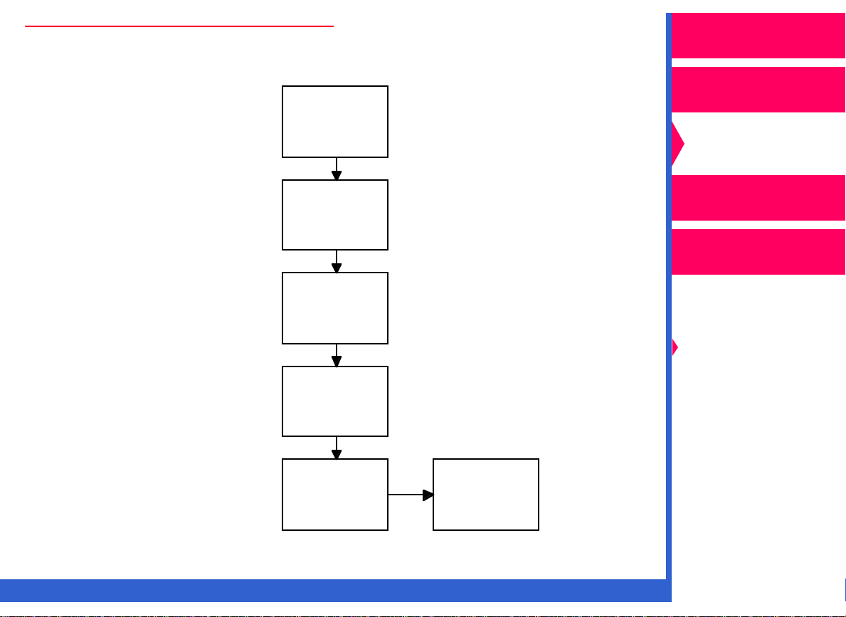
Steps to Create Color Connector Files
Run color
Step 1
connector
application
Operator’s Guide
Printing
Guide
Color Management
CONTENTS
Step 2
Step 3
Step 4
Step 5
INDEX
Select and
drag
transforms to
template
Select desired
color connector
options
Save the color
connector file
Send color
connector file
to printer as
a default
or
Print using color
connector file
SEARCH
Calibration
Network
Interface Guide
Color Management
Options
Using Color
Connector
Using PANTONE®
Color
HELP
Page 7
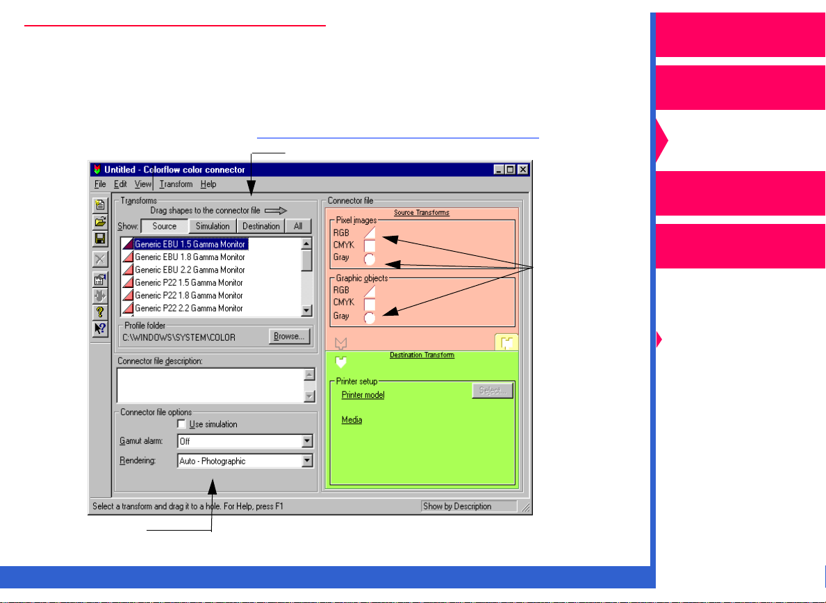
Color Connector Window
Operator’s Guide
When you access the color connector application, the color connector
window appears. From this window you can create your color connector
files. For descriptions of the menu items and dialog boxes used in the
color connector application, ref
er to “Menus and Dialog Boxes.”
Transforms List
Template
Sockets
Printing
Guide
Color Management
Calibration
Network
Interface Guide
Color Management
Options
Using Color
Connector
Using PANTONE®
Color
Options
CONTENTS
INDEX
SEARCH
HELP
Page 8

Getting Ready to Use Color Connector
Operator’s Guide
The following steps describe how to get started with color connector.
NOTE: The illustrations in this section show Windows dialog boxes. The
dialog boxes for Macintosh are similar and have identical
functionality.
1.
Install the software for color connector and the printing software
including the export module. The software is included on the CD that
came with your printer.
IMPORTANT: For Macintosh users, if you upgrade to ColorSyncTM 2.5,
when
you restart the color connector application, a dialog
box appears that explains that the profiles shipped with the
8670 printer were moved to the new ColorSync Profiles
folder. Select the new ColorSync Profiles folder as the
default location for the ICC Profiles
2.
Put any additional ICC Profiles in the folder containing your ICC
Profiles that were shipped with the printer. The default folder for the
ICC Profiles is:
•
for Windows systems, Windows\System\Color.
•
for Macintosh systems:
.
Printing
Guide
Color Management
Calibration
Network
Interface Guide
Color Management
Options
Using Color
Connector
Using PANTONE®
Color
–
if you are using ColorSyncTM 2.1, System
Folder:Preferences:ColorSync
CONTENTS
INDEX
TM
Profiles.
SEARCH
HELP
Page 9

–
if you are using ColorSyncTM 2.5, System Folder:ColorSync
Profiles.
Operator’s Guide
NOTE: Before you use color connector for the first time, you may wish to
complete the tutorial that is included on the CD.
3.
Start the color connector application.
Printing
Guide
Color Management
Calibration
Network
Interface Guide
Color Management
Options
Using Color
Connector
Using PANTONE®
Color
CONTENTS
INDEX
SEARCH
HELP
Page 10
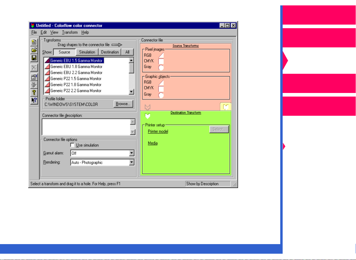
The color connector window appears.
Operator’s Guide
Printing
Guide
Color Management
Calibration
Network
Interface Guide
Color Management
Options
Using Color
Connector
Using PANTONE®
Color
CONTENTS
INDEX
SEARCH
HELP
Page 11
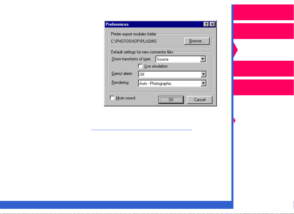
4.
Pull down the File menu, and select “Preferences”.
5.
Click on
Macintosh) in the Printer
export modules folder
portion of the Preferences
dialog box. A file selection
dialog box appears.
6.
Locate the Plug-ins
(Printing) folder, and
select the export module
for the 8670 printer.
Browse (Select
in
Operator’s Guide
Printing
Guide
Color Management
Calibration
Network
Interface Guide
Color Management
Options
NOTE: For descriptions of the options in the Default settings for new
connector files box, ref
Follow the procedures on the following screens to build your own color
connector files.
CONTENTS
INDEX
er to “Menus and Dialog Boxes.”
SEARCH
HELP
Using Color
Connector
Using PANTONE®
Color
Page 12
Creating a Color Connector File
1.
Select puzzle pieces from the
list of transforms (on the left
side of the color connector
window) that represent the
sources of color data.
Operator’s Guide
Printing
Guide
Color Management
The puzzle pieces are extracted
from the ICC Profiles. Drag the
pieces to the appropriate
Source Transforms sockets in
the template on the right side of
the color connector window.
The template has six sockets for source transforms. You can apply
independent color management to up to six different kinds of sources
in one Postscript job:
•
RGB, CMYK, and grayscale pixel images such as TIFF files or
scanned photographs.
•
RGB, CMYK, and grayscale graphic images such as EPS files or
text.
IMPORTANT: If your file contains a source that uses PANTONE® Color,
leave the socket empty for that color space.
CONTENTS
INDEX
SEARCH
HELP
Calibration
Network
Interface Guide
Color Management
Options
Using Color
Connector
Using PANTONE®
Color
Page 13
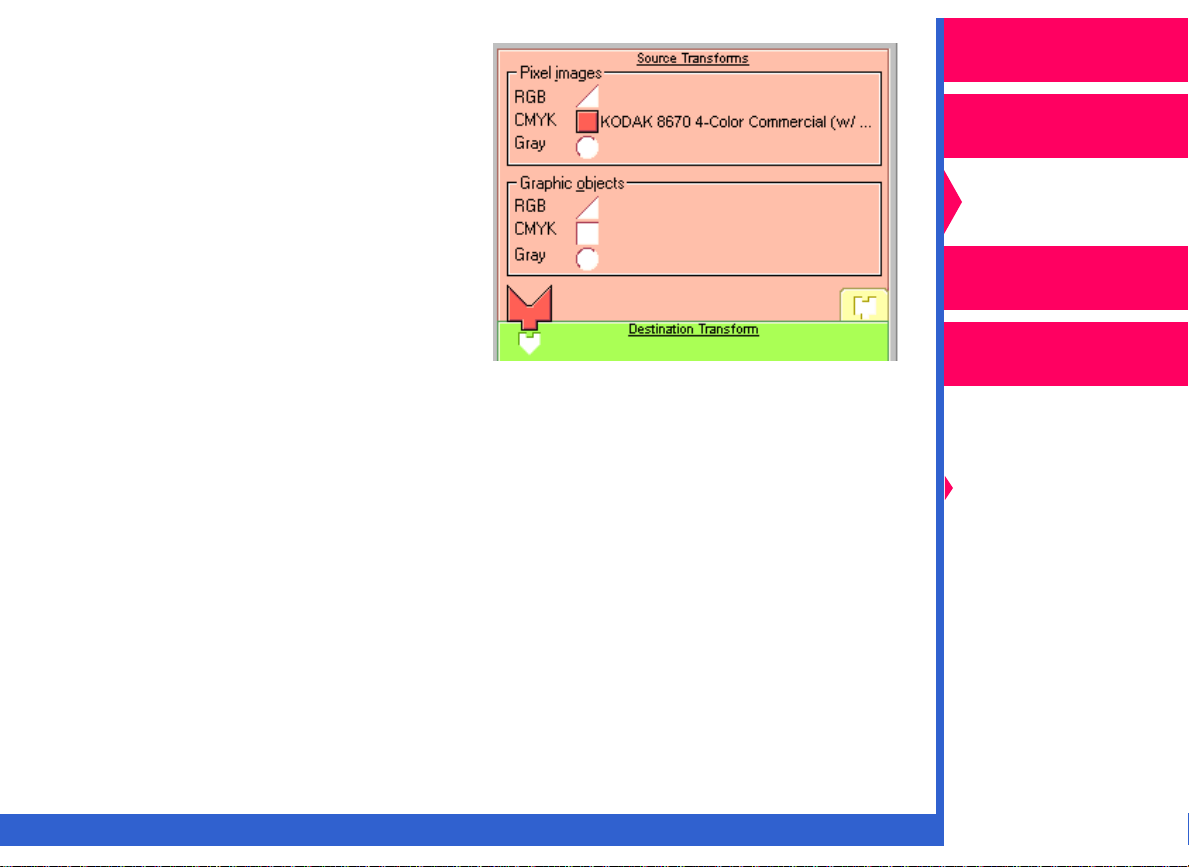
After you drag the first source
transform to the template, the
source puzzle piece appears in
its socket indicating that the
minimum requirement for source
transforms is complete.
Operator’s Guide
Printing
Guide
Color Management
Calibration
Network
Interface Guide
NOTE: If you wish to change the transform you placed in the socket:
•
select a new transform; and drag it to the socket. It replaces the
previously-selected transform.
To delete a transform from a color connector socket:
•
select the transform.
•
pull down the Transforms menu, and select “Delete Transform”
on Windows systems or “Clear Transform” on Macintosh
systems.
CONTENTS
INDEX
SEARCH
HELP
Color Management
Options
Using Color
Connector
Using PANTONE®
Color
Page 14
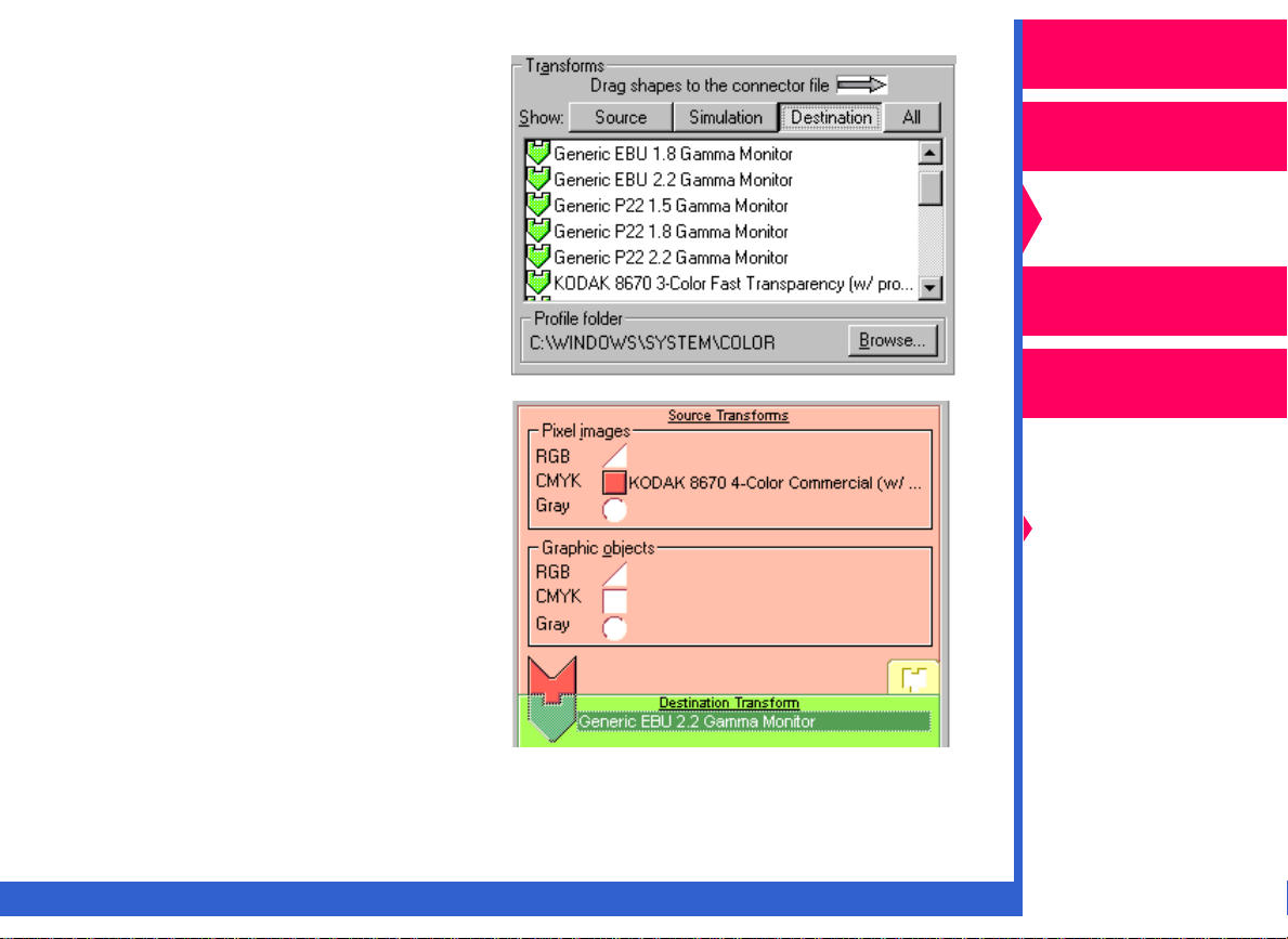
2.
Scroll through the list of
transforms, and select a
destination transform that
matches your output device.
Drag the green puzzle piece
for the destination transf orm to
the Destination Transform
socket in the color connector
template.
Operator’s Guide
Printing
Guide
Color Management
Calibration
The destination puzzle piece
then appears over its place
holder indicating that the
requirement for a destination
transform is complete.
CONTENTS
INDEX
SEARCH
Network
Interface Guide
Color Management
Options
Using Color
Connector
Using PANTONE®
Color
HELP
Page 15
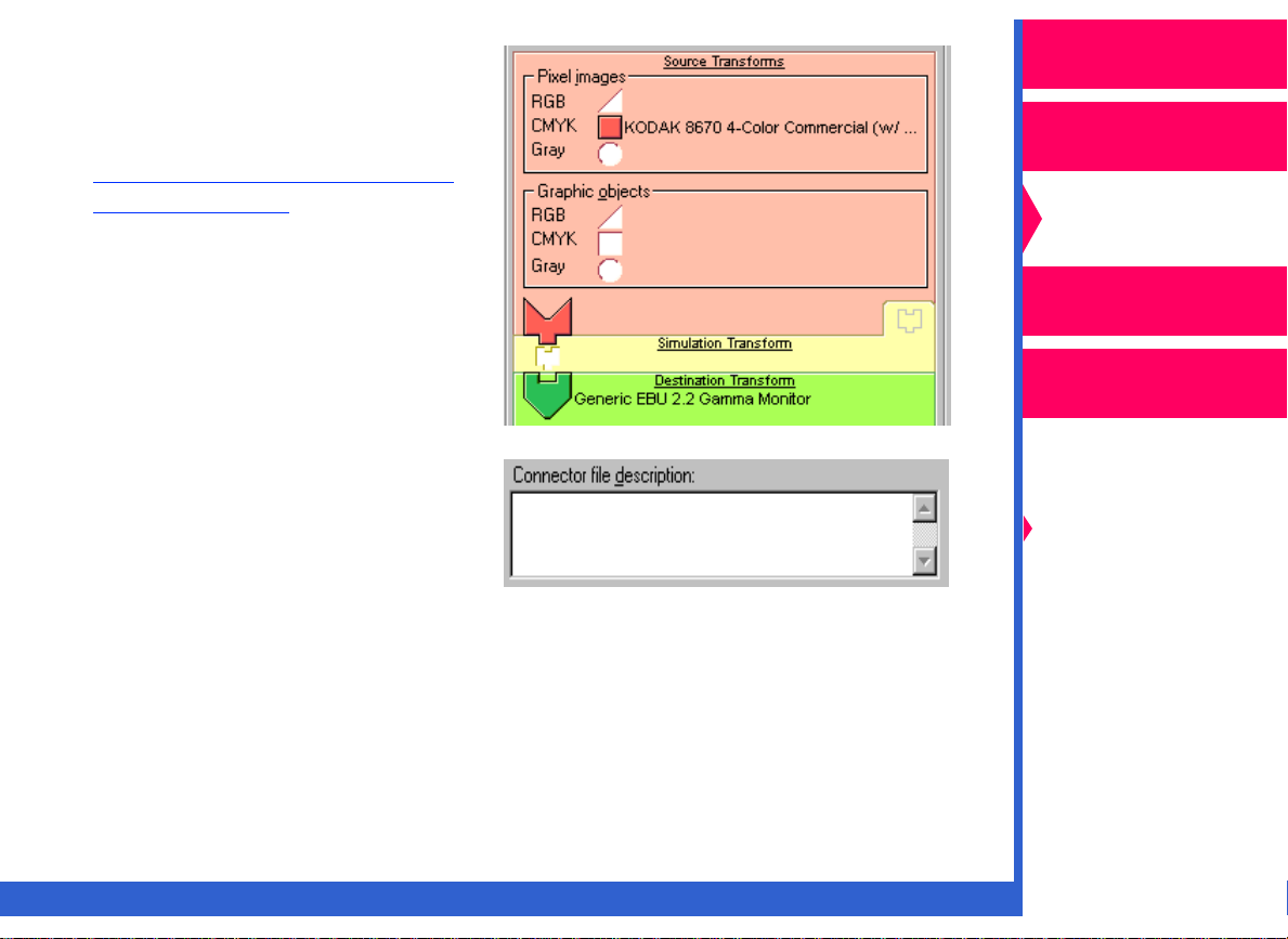
3.
Using a simulation transform
from the Transforms list is
optional. For instructions on
using the Simulation option,
er to “Simulating Another
ref
Output Device.”
Operator’s Guide
Printing
Guide
Color Management
Calibration
Network
Interface Guide
4.
You may enter a description
of the color connector file you
created in the Connector file
description box. Entering a
description will help you to
identify the file when printing.
5.
Pull down the File menu, and select “Save”.
CONTENTS
INDEX
SEARCH
Color Management
Options
Using Color
Connector
Using PANTONE®
Color
HELP
Page 16
Matching Your Monitor to Your Printer’s Output
Operator’s Guide
The following steps describe how to build a connector file so that the
colors in your computer monitor match the output from your printer.
NOTE: Monitors vary with model, age, and manufacturer. For optimum
results, make sure that the ICC Profile for your specific monitor
model is in the Transforms list.
Your monitor should be calibrated. Refer to the documentation
that came with your monitor for instructions on how to calibrate it.
1.
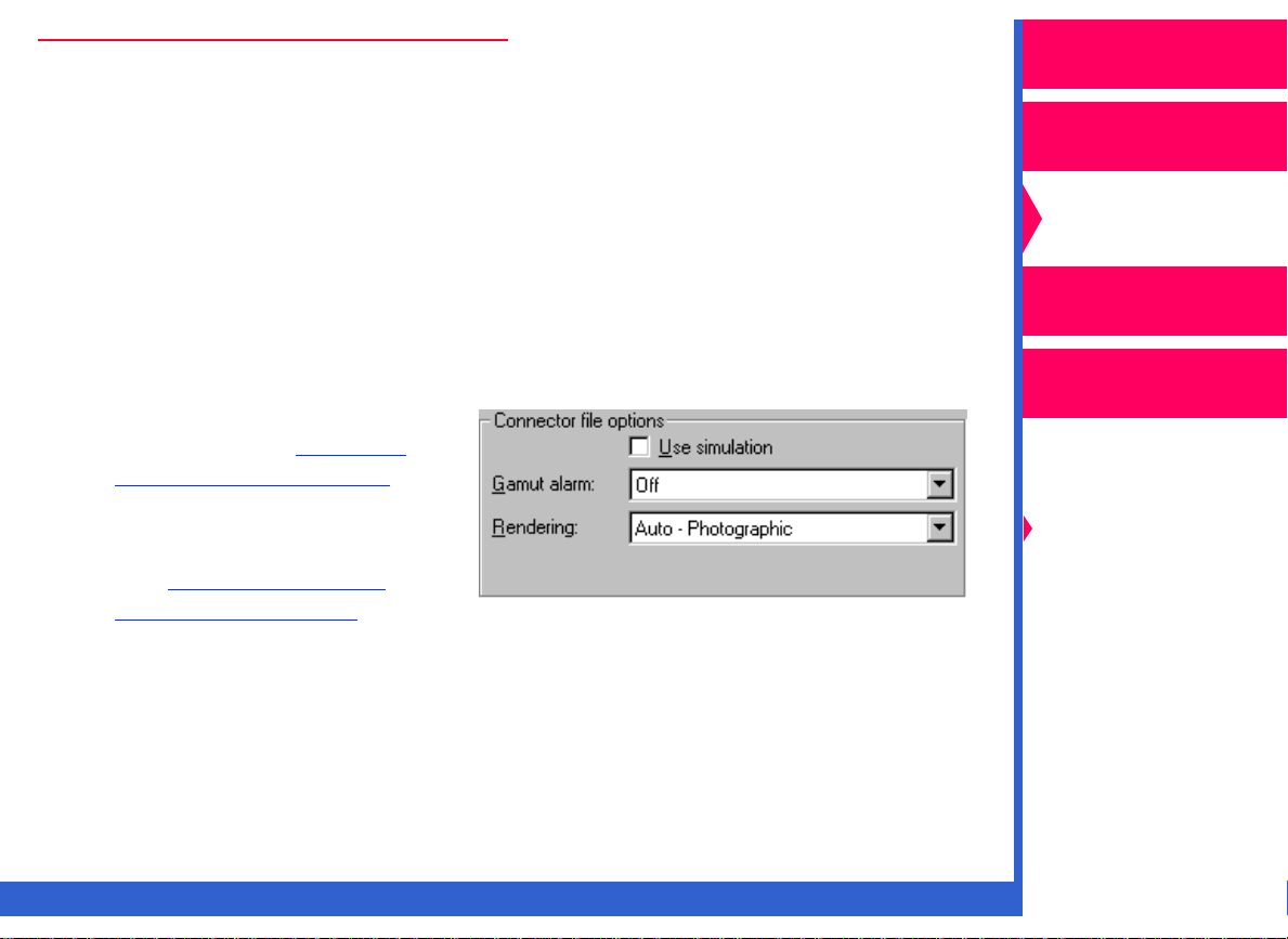
In the Connector file options box:
•
make your selection for
Gamut alarm. Ref
“Using Gamut Alar m.”
•
select the rendering intent
that is appropriate for your
job. Ref
Rendering Intents.”
er to “Setting
er to
Printing
Guide
Color Management
Calibration
Network
Interface Guide
Color Management
Options
Using Color
Connector
Using PANTONE®
Color
CONTENTS
INDEX
SEARCH
HELP
Page 17
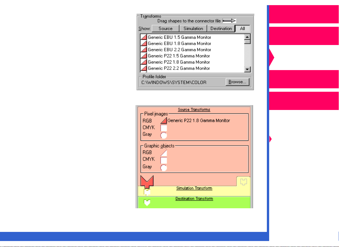
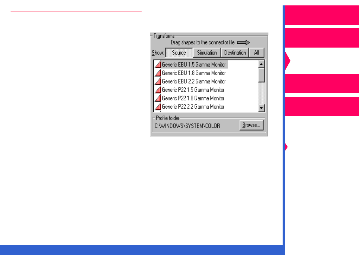
2.
From the T ransf orms list, select
a pink triangle puzzle piece
that matches the name of your
monitor.
3.
Drag and drop the pink
triangle puzzle piece to
the appropriate Source
Transforms socket. The
piece appears in the RGB
or Gray socket. You will
hear a click.
Operator’s Guide
Printing
Guide
Color Management
Calibration
Network
Interface Guide
Color Management
Options
Using Color
Connector
Using PANTONE®
Color
CONTENTS
INDEX
SEARCH
HELP
Page 18
NOTE: If you wish to add a simulation transform to the template so that
the job matches the output from another printing system, ref
“Simulating Another Output Device.”
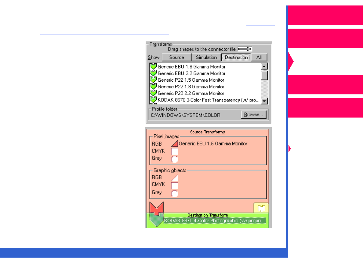
4. From the Transforms list,
select a green puzzle piece
that matches your output
device and media
combination.
er to
Operator’s Guide
Printing
Guide
Color Management
Calibration
Network
Interface Guide
5. Drag and drop the green
puzzle piece to the
Destination Transform
socket.
CONTENTS
INDEX
SEARCH
Color Management
Options
Using Color
Connector
Using PANTONE®
Color
HELP
Page 19
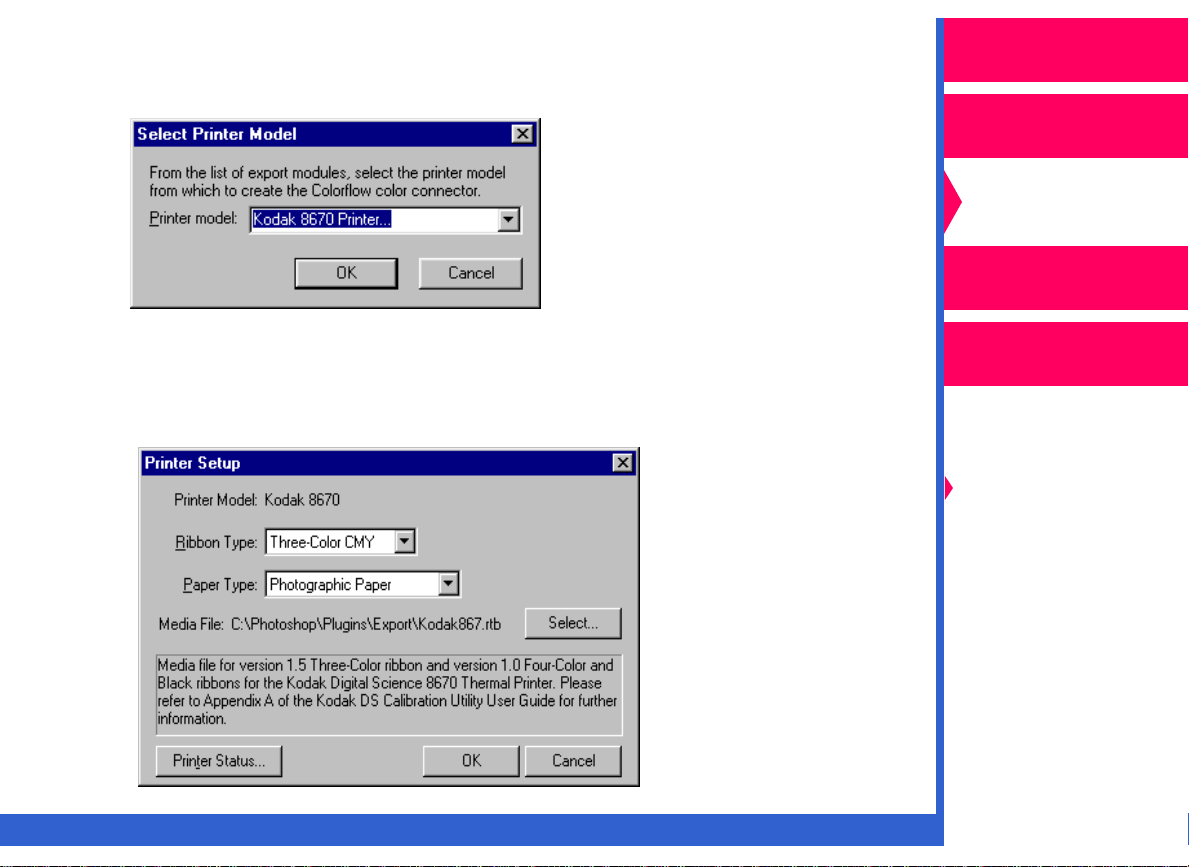
NOTE: If you selected a destination transform that was extracted from an
ICC Profile other than one that came with the 8670 printer, the
Select Printer dialog box appears.
Operator’s Guide
Printing
Guide
Color Management
Calibration
Use the Printer model pull-down list to select the model of the
OK
printer you are using. Click on
A dialog box similar to the one below appears that allows you to
select the media for the printer.
CONTENTS INDEX SEARCH HELP
.
Network
Interface Guide
Color Management
Options
Using Color
Connector
Using PANTONE®
Color
Page 20
The Printer Setup screen may appear differently depending on
the printer you are using.
Operator’s Guide
Make your media choices.
OK
Click on
6. You may enter a description
of the color connector file
you created in the Connector
file description box. Entering
a description will help you to
identify the file when
printing.
7. Pull down the File menu, and select “Save”.
8. To send the connector file to the printer to save as a default, ref
“Expor ting a Color Connector to the Printer as a Default.”
.
er to
Printing
Guide
Color Management
Calibration
Network
Interface Guide
Color Management
Options
Using Color
Connector
Using PANTONE®
Color
CONTENTS INDEX SEARCH HELP
Page 21

Color Managing Multiple Sources
Operator’s Guide
The following steps describe how to build a connector file that applies
color management to multiple sources in one PostScript job.
NOTE: You can apply color management to up to six different types of
source transforms:
• RGB, CMYK, and grayscale pixel images such as TIFF files or
scanned photographs.
• RGB, CMYK, and grayscale graphic images such as EPS files
or text.
You cannot apply color management to multiple images from
different sources in the same color space. For example, you
cannot apply color management separately to two pixel RGB
images.
1. In the Connector file options
box:
• make your selection for
Gamut alarm. Ref
“Using Gamut Alar m.”
• select the rendering intent
that is appropriate for your
job. Ref
Rendering Intents.”
er to “Setting
er to
Printing
Guide
Color Management
Calibration
Network
Interface Guide
Color Management
Options
Using Color
Connector
Using PANTONE®
Color
CONTENTS INDEX SEARCH HELP
Page 22

2. From the Transforms list, select
the pink puzzle pieces that
match the images or objects to
which you wish to apply color
management.
Operator’s Guide
Printing
Guide
Color Management
Calibration
Network
Interface Guide
NOTE: Make sure that the images or objects you select have not had any
previous color management applied to them.
If your file contains a source that uses PANTONE
the socket empty for that color space.
CONTENTS INDEX SEARCH HELP
® Color, leave
Color Management
Options
Using Color
Connector
Using PANTONE®
Color
Page 23

3. Drag and drop the pink puzzle
pieces to the appropriate
sockets in the Source
Transforms section of the
template.
Operator’s Guide
Printing
Guide
Color Management
Calibration
Network
Interface Guide
NOTE: If you wish to add a simulation transform to the template so that
the job matches the output from another printing system, ref
“Simulating Another Output Device.”
4. From the Transforms list, select
a green arrowhead-shaped
puzzle piece that matches your
output device and media
combination.
CONTENTS INDEX SEARCH HELP
er to
Color Management
Options
Using Color
Connector
Using PANTONE®
Color
Page 24

5. Drag and drop the puzzle
piece to the Destination
Transform socket in the
template.
Operator’s Guide
Printing
Guide
Color Management
Calibration
Network
Interface Guide
Color Management
Options
Using Color
Connector
Using PANTONE®
Color
CONTENTS INDEX SEARCH HELP
Page 25

NOTE: If you selected a destination transform that was extracted from an
ICC Profile other than one that came with the 8670 printer, click
Select
on
window.
The Select Printer Model dialog box appears.
in the Printer setup portion of the color connector
Operator’s Guide
Printing
Guide
Color Management
Calibration
Network
Interface Guide
Use the Printer model pull-down list to select the printer model.
A dialog box similar to the one below appears allowing you to
select the media for the printer.
CONTENTS INDEX SEARCH HELP
Color Management
Options
Using Color
Connector
Using PANTONE®
Color
Page 26

NOTE: The Printer Setup dialog box may appear differently depending
on the export module you are using.
Operator’s Guide
OK
6. Select the correct media for the printer. Click on
7. You may enter a description
of the color connector file
you created in the
Connector file description
box. Entering a description
will help you to identify the
file when printing.
8. Pull down the File menu, and select “Save”.
9. To send your connector file to the printer to save as a default, ref
“Expor ting a Color Connector to the Printer as a Default.”.
.
Printing
Guide
Color Management
Calibration
Network
Interface Guide
er to
Color Management
Options
Using Color
Connector
Using PANTONE®
Color
CONTENTS INDEX SEARCH HELP
Page 27

Simulating Another Output Device
Operator’s Guide
The following steps describe how to build a color connector file to produce
colors that simulate the look of other printing systems such as SWOP or
Euroscale.
1. In the Connector file options
box, select “Use simulation”.
2. Create a color connector file by selecting and dragging the
appropriate source and destination transform puzzle pieces to the
template. To create a color connector file that matches your monitor
to the printer’s output, ref
Printer’s Output.” To create a color connector file that manages
multiple sources, ref
er to “Matching Your Monitor to Your
er to “Color Managing Multiple Sources.”
Printing
Guide
Color Management
Calibration
Network
Interface Guide
Color Management
Options
Using Color
Connector
Using PANTONE®
Color
CONTENTS INDEX SEARCH HELP
Page 28

3. From the Transforms list, select
a yellow puzzle piece that
matches the name of the output
device you wish to simulate.
4. Drag and drop the puzzle piece
in the Simulation Transform
socket of the template.
NOTE: To send your color
connector file to the printer
as a default, ref
“Expor ting a Color
Connector to the Printer as
a Default.”
er to
Operator’s Guide
Printing
Guide
Color Management
Calibration
Network
Interface Guide
Color Management
Options
Using Color
Connector
Using PANTONE®
Color
CONTENTS INDEX SEARCH HELP
Page 29

Using Gamut Alarm
Operator’s Guide
Gamut alarm is a feature that allows you to determine if the simulation or
destination devices you selected for your connector file are capable of
accurately reproducing the colors of the previous device.
When you select one of the gamut alarm modes, any areas of your image
that are out of gamut are printed in black. All other areas are printed in
white.
Printing
Guide
Color Management
Calibration
Network
Interface Guide
Color Management
Options
Using Color
Connector
Using PANTONE®
Color
CONTENTS INDEX SEARCH HELP
Page 30

NOTE: When you set gamut alarm to
either “Destination” or
“Simulation”, the puzzle
pieces in the sockets are
black.
Operator’s Guide
Printing
Guide
To set gamut alarm:
NOTE: To use gamut alarm in the
Simulation mode, be sure
that you select the “Use
simulation” check box.
1. Pull down the Gamut alarm list,
and select either:
• “Simulation” to determine if the colors of the source transform are
out of the gamut of the simulation device
or
• “Destination” to determine if the colors of the simulation or source
device are out of the gamut of the destination device.
2. Create your color connector file. Ref
Sources.” When you print the file, any out-of-gamut areas are printed
in black.
3. To adjust the color representation in any out-of-gamut areas, ref
“Setting Render ing Intents.”
er to “Color Managing Multiple
Color Management
Calibration
Network
Interface Guide
Color Management
Options
Using Color
Connector
Using PANTONE®
Color
er to
CONTENTS INDEX SEARCH HELP
Page 31

Setting Rendering Intents
Operator’s Guide
Rendering intents control the ways in which color connector translates the
colors from the source transform to the simulation transform and the
source or simulation transform to the destination transform when they are
out of gamut. The rendering intent deals with the color differences
between the transforms. For example, if the color of a scanned image is
out of the gamut of the destination device, the destination device cannot
reproduce that color. The color must be represented by another color that
is close to the desired color. Rendering intents deter mine how out-ofgamut colors are substituted.
Automatic Rendering
You can let color connector set Rendering for you by selecting one of the
automatic settings from the Rendering drop-down list box. The automatic
settings set rendering intents for the individual transforms by comparing
their color gamuts. Both of these settings give a pleasing look but not
necessarily the most accurate reproduction.
Custom Rendering
To more closely control the way in which color connector adjusts the
differences in color representation, use the Custom Rendering
option.This option allows you to set the rendering intents individually for
all the source and simulation transforms.
Printing
Guide
Color Management
Calibration
Network
Interface Guide
Color Management
Options
Using Color
Connector
Using PANTONE®
Color
CONTENTS INDEX SEARCH HELP
Page 32

Setting Automatic Rendering
To set automatic rendering intents:
Pull down the Rendering drop-down list, and select either:
• “Auto—Photographic” for
scanned photographs. Color
connector attempts to
maintain the correct hue by
adjusting the color saturation
for the out-of-gamut colors
Operator’s Guide
Printing
Guide
Color Management
Calibration
or
• “Auto—Presentation” for
computer-generated graphics,
charts, graphics. Color
connector tries to maintain
saturation at the expense of
the correct hue for the out-ofgamut colors.
CONTENTS INDEX SEARCH HELP
Network
Interface Guide
Color Management
Options
Using Color
Connector
Using PANTONE®
Color
Page 33

Setting Custom Rendering
Do the following steps to set custom rendering.
NOTE: If you wish to set custom rendering for more than one puzzle
piece in the template, you need to repeat this procedure for each
piece.
1. Pull down the Rendering
drop-down list box, and
select “Custom”.
2. Build the connector file you need for your job. Ref
Managing Multiple Sources.”
er to “Color
Operator’s Guide
Printing
Guide
Color Management
Calibration
Network
Interface Guide
Color Management
Options
Using Color
Connector
3. Double-click on the source or simulation puzzle piece in the color
connector socket in the template for which you wish to set custom
rendering.
CONTENTS INDEX SEARCH HELP
Using PANTONE®
Color
Page 34

The Transform Information dialog box appears.
Operator’s Guide
Printing
Guide
Color Management
Calibration
Network
Interface Guide
Color Management
Options
Using Color
Connector
Using PANTONE®
Color
A Recommendation box gives you two recommended settings based
on a comparison of gamuts. If you select a different rendering intent,
the Effect box changes to describe the expected results.
CONTENTS INDEX SEARCH HELP
Page 35

4. Pull down the Rendering intent list box, and select a rendering intent
from the following options:
Operator’s Guide
• Perceptual—compresses the gamut of the image while maximizing
the color. Use this rendering intent for photographic images.
• Saturation—compresses the gamut of the image while maximizing
the color saturation. Use this rendering intent for presentation
graphics.
• Relative Colorimetric—compresses the gamut of the image for
brightness, and clips the gamut for color. Use this rendering intent
when you wish to match a particular color.
• Absolute Colorimetric—Clips the gamut of the image. Use this
rendering intent when you wish to match a particular color and
simulate the background of the paper.
OK
5. Click on
.
Printing
Guide
Color Management
Calibration
Network
Interface Guide
Color Management
Options
Using Color
Connector
Using PANTONE®
Color
CONTENTS INDEX SEARCH HELP
Page 36

Exporting a Color Connector to the Printer as a
Operator’s Guide
Default
Color Connector Memory Locations in Printers
Printers that support color connector contain color management memor y
locations. These memory locations store color management information,
and are defined by a media combination for ribbon and paper.
For example, if a printer has two ribbon types and two paper types, the
printer might have four memory locations:
• Commercial paper with a CMYK ribbon
• Commercial paper with a black ribbon
• Publication paper with a CMYK ribbon
• Publication paper with a black ribbon
When you send a job to the printer that uses the media combination for
that memory location, the default connector file is applied if you do not
select another connector file.
Exporting a connector file as a default stores frequently-used color
management information permanently in the printer. This eliminates the
need for individual users to apply color management to their jobs as long
as they use the default media combinations.
Printing
Guide
Color Management
Calibration
Network
Interface Guide
Color Management
Options
Using Color
Connector
Using PANTONE®
Color
CONTENTS INDEX SEARCH HELP
Page 37

Exporting a Color Connector File to be a Printer Default
After you create your connector file, do the following steps to send it to
the printer as a default:
1. Make sure that you save the file.
Operator’s Guide
Printing
Guide
2. From the File menu, select “Expor t As Printer’s Default”.
The “Select Printer Model” dialog box appears.
3. Select the printer model from the drop-down list.
OK
4. Click on
NOTE: If this is the first time you have created a connector file, a dialog
box appears asking you to locate the media file. Click on
Select “8670 Media V150” in the dialog box that appears. Click on
Open
.
OK
.
.
Color Management
Calibration
Network
Interface Guide
Color Management
Options
Using Color
Connector
Using PANTONE®
Color
CONTENTS INDEX SEARCH HELP
Page 38

Selecting a Printer
Macintosh systems
If the 8670 printer:
• has a network
connection, click on
Network
Select a Kodak
Professional 8670
thermal printer
dialog box.
In the selection box
that opens, choose
the correct 8670
printer. Click on
to return to the
Select a Kodak
Professional 8670
thermal printer dialog box.
• has a SCSI connection to your computer, click on the radio button for
the correct 8670 printer.
in the
OK
Operator’s Guide
Printing
Guide
Color Management
Calibration
Network
Interface Guide
Color Management
Options
Using Color
Connector
Using PANTONE®
Color
CONTENTS INDEX SEARCH HELP
Page 39

Windows systems
If the 8670 printer:
• has a SCSI
connection, click on
the radio button f or the
correct 8670 printer.
• has a network
connection, click on
Network
Browse
the correct printer in
the Browse for Printer
dialog box that opens.
Click on
Network Printer dialog
box to return to the
Select a Printer dialog box.
• has a parallel connection, click on the radio button for either LPT1 or
LPT2 to select the printer.
. Click on
, and locate
OK
in the
Operator’s Guide
Printing
Guide
Color Management
Calibration
Network
Interface Guide
Color Management
Options
Using Color
Connector
Using PANTONE®
Color
NOTE: If your host computer has more than one SCSI host adapter
installed, pull down the SCSI Host Adapter list. Select the port
address for the SCSI host adapter connected to the 8670 printer.
CONTENTS INDEX SEARCH HELP
Page 40

The Printer Default
Connector Files dialog
box appears.
NOTE: If you hav e more than
one 8670 printer,
click on
Printer
correct printer for
exporting.
Select
to locate the
Operator’s Guide
Printing
Guide
Color Management
Calibration
5. Click on
Set as Printer
Default.
If your printer has a bidirectional connection
such as SCSI or
AppleTalk, the memory
location for the connector
file you exported will be
added to the list in the
Printer default connector
files window. If the
connector file does not
appear, click on
If your printer has a parallel connection, this information does not
appear in the Printer default connector files window.
CONTENTS INDEX SEARCH HELP
Update
.
Network
Interface Guide
Color Management
Options
Using Color
Connector
Using PANTONE®
Color
Page 41

NOTE: You are prompted if the connector file you are sending to the
printer as a default has the same media combination as another
default connector file. If you wish to send a connector file to the
printer as a default for a media combination that already exists,
delete all the default connector files before you send the new
default to the printer. You can then resend the other default
connector files to the printer. Ref
Files.”
er to “Deleting Color Connector
Operator’s Guide
Printing
Guide
Color Management
Calibration
Network
Interface Guide
Color Management
Options
Using Color
Connector
Using PANTONE®
Color
CONTENTS INDEX SEARCH HELP
Page 42

Deleting Color Connector Files
Operator’s Guide
Clicking on
Printer Default Connector
Files dialog box deletes all
the default color connector
files stored in the 8670
printer.
Delete All
in the
Printing
Guide
Color Management
Calibration
Network
Interface Guide
Color Management
Options
Using Color
Connector
Using PANTONE®
Color
CONTENTS INDEX SEARCH HELP
Page 43

Exporting a Color Connector File as an ICC DeviceLink
Profile
You can export a color connector file as a DeviceLink profile so that it can
be used with other color management applications.
Operator’s Guide
Printing
Guide
NOTE: The color connector file that you export as a DeviceLink profile
can contain only one source transform.
1. From the File menu, select “Expor t As ICC DeviceLink Profile”.
2. In the dialog box that appears, enter a name for the color connector
file. Select the folder where you want the file to reside.
OK
3. Click on
.
Color Management
Calibration
Network
Interface Guide
Color Management
Options
Using Color
Connector
Using PANTONE®
Color
CONTENTS INDEX SEARCH HELP
Page 44

Using PANTONE® Color
Operator’s Guide
A printer calibrated by PANTONE Inc. has custom-developed CMYK
combinations for every color in the PANTONE® MATCHING SYSTEM
(coated stock only and excluding specialty colors such as metallics,
fluorescents and double impressions). While some PANTONE®* colors
may not be achievable on every printer, the closest possible simulation for
each is found.
PANTONE® provides a calibrated table and a collection of palette files for
PS
use with the Kodak Professional 8670
enable you to load the color table calibrated for the 8670 printer as a
usable color palette in the most popular PANTONE®-licensed desktop
publishing programs.
printer (8670 printer). The files
IMPORTANT: The palette files provided are calibrated only f or this printer.
If you create color separations, recolor the graphics using
the built-in PANTONE
PANTONE
There are many variables in the process reproduction of colors generated
by the 8670 printer, any one of which may affect the quality of the
PANTONE® color simulation including:
• type of paper used
®
-licensed application.
®
color tables supplied by the
Printing
Guide
Color Management
Calibration
Network
Interface Guide
Color Management
Options
Using Color
Connector
Using PANTONE®
Color
• type of ink film used
*PANTONE Inc.’s check-standard trademark for color reproduction and color reproduction
materials.
CONTENTS INDEX SEARCH HELP
Page 45

• effective final resolution
• dot structures/halftones
For optimal results, we recommend that you use the following materials:
• Kodak Ektatherm XLS four-color ribbon/CMYK
Operator’s Guide
Printing
Guide
• Kodak Ektatherm XLS print paper/commercial grade/9.5 x 14 inches
• Kodak Ektatherm XLS print paper/publication grade/9.5 x 14 inches
Installing the Tables and Palette Files
The File Library folder on the CD contains a collection of applicationspecific, visually-calibrated palettes for both Macintosh and Windows
platforms. Locate the file for the applications and platform you are using.
Copy the palettes from the File Library folder on the CD to the appropriate
application folder on your hard drive, or use them from the CD.
EPSF, TIFF, and Acrobat Charts
Ready-to-use calibrated palettes for a variety of applications are included
on the CD. For applications not supported, a PANTONE® calibrated color
chart in EPS and TIFF formats is included on the CD. You can bring your
custom colors into these applications by using any of the appropriate
color chart formats. The application must have a tool that you can use to
pick up colors from an imported graphic. Use this approach if your custom
color palette contains colors that are similar.
Color Management
Calibration
Network
Interface Guide
Color Management
Options
Using Color
Connector
Using PANTONE®
Color
CONTENTS INDEX SEARCH HELP
Page 46

Loading the Palette Files
Operator’s Guide
The instructions in this section describe how to load the PANTONE®
Palettes for the 8670 printer into the supported applications.
Adobe Illustrator
Load the color palette for Adobe Illustrator through the Open command
from the File menu (version 4.x) or the Import Style command (Macintosh
version 5.x or higher) on the File menu. Once opened, the colors are
available in the Paint Styles dialog box. After you save a file, open Adobe
Illustrator and the custom palette. The custom colors are added to the
color palette.
To open a color palette in Adobe Illustrator Version 6 or lower:
1. Select “Import Styles” or “Open” from the File menu.
2. Locate the color palette for Adobe Illustrator.
NOTE: The color palette has an .ai extension and an Adobe Illustrator
icon to its left in the Get File dialog box.
3. Select the color palette. Click on
palette name.
The custom color palette is available in the Paint Styles dialog box
after you select the custom color option.
Open
, or double-click on the color
Printing
Guide
Color Management
Calibration
Network
Interface Guide
Color Management
Options
Using Color
Connector
Using PANTONE®
Color
CONTENTS INDEX SEARCH HELP
Page 47

To open a color palette in Adobe Illustrator version 7:
Select “Window” and then “Swatch Libraries - Other Library” from the
menu bar.
To use colors from your color palette:
Operator’s Guide
Printing
Guide
1. Draw or select an item to color.
2. Select “Paint Style” from the Object menu.
The Paint Style window appears.
Custom
color
square
3. Click on the custom color square (the underlined square, third from
the right) in the Custom area.
The color list appears in the scrolling window.
4. Select any color from the alphabetical list.
Color Management
Calibration
Network
Interface Guide
Color Management
Options
Using Color
Connector
Using PANTONE®
Color
CONTENTS INDEX SEARCH HELP
Page 48

Adobe Photoshop
Operator’s Guide
In Adobe Photoshop you cannot define the names for colors—just the
colors themselves. If you are working with an extensive palette or you
want to see the color names, ref
Make sure that your image is set to CMYK Color.
To open a color palette in Adobe Photoshop version 3:
1. Select “Palettes”, “Show Swatches” from the Window menu if the
palette swatches are not displayed.
2. Select “Load Swatches” by clicking the arrow in the upper right corner
of the Swatches window.
3. Select the color palette you wish to import. Click on
To use a color from your color palette:
1. Click on the Paint Bucket tool.
2. Select one of the custom colors in the Swatches window.
3. Click anywhere on an object to fill it with the selected color.
4. Make sure that the image is set to CMYK Color mode before you
apply the calibrated colors.
er to “EPSF, TIFF, and Acrobat Charts.”
Open
.
Printing
Guide
Color Management
Calibration
Network
Interface Guide
Color Management
Options
Using Color
Connector
Using PANTONE®
Color
CONTENTS INDEX SEARCH HELP
Page 49

Macromedia FreeHand
Operator’s Guide
To open a color palette in FreeHand 3.x
1. Open an existing document, or create a new document.
2. Select "Window" from the View menu. Choose “Colors” from the
Window menu.
3. Click on the arrow on the right of the Colors window, and select
“Import”.
4. Select the color palette you saved,
and click on
To use colors from your color palette:
1. Select the object you want to color.
Open
.
Printing
Guide
Color Management
Calibration
Network
Interface Guide
Color Management
Options
Using Color
Connector
Using PANTONE®
Color
2. Select the Fill box from the Colors window.
CONTENTS INDEX SEARCH HELP
Page 50

3. Choose:
– “Fill” if you want to fill the object.
– “Line” if you want to fill the line (border).
– “Both” if you want to fill both the object and its border.
Operator’s Guide
Printing
Guide
4. Select a color in the Colors window to apply the color to the selected
object.
Macromedia FreeHand 4.0—7.0
Macromedia FreeHand versions 4.0—7.0 support Binar y Color Format
(BCF) and ASCII Color Format (ACF).
You can store the color palette anywhere. For Macintosh you can store
the palette in the Color folder in the Adobe folder or in your System folder.
For Windows, you can store the palette in the Color folder in the
Usenglish folder or in the FreeHand folder. If you store the palette in the
Color folder, it appears on the Options menu in the Color List dialog box
the next time you open FreeHand. After you bring an ACF palette into
FreeHand, the program automatically creates a BCF file for you.
To open a color palette in FreeHand 4.0—7.0:
1. Create a new document, or open an existing FreeHand document.
2. Select "Color List" from the Window menu.
Color Management
Calibration
Network
Interface Guide
Color Management
Options
Using Color
Connector
Using PANTONE®
Color
CONTENTS INDEX SEARCH HELP
Page 51

3. Open the Options menu in the Color list palette that opens. If you
stored your color palette anywhere else, select “Impor t” from the
Options menu. Select your color palette, and click on
To use colors in FreeHand 4.0—7.0:
Open
.
Operator’s Guide
Printing
Guide
1. Drag the color square you want onto the object to which you want to
apply the color from the Color List dialog box.
2. Drag the color square into the center of the object to fill the object
with the selected color or onto the border of an object to apply the
selected color to the border.
Adobe PageMaker 5.0/6.0/6.5
Store the color palettes in the following folders:
Adobe PageMaker 5.x on Macintosh—Color folder in the System folder
Adobe PageMaker 5.x on Windows—PM5\Usenglish\Color folder
Adobe PageMaker 6.x on Macintosh—Colors folder inside the RSRC
folder in the PM6 folder.
Adobe PageMaker 6.x on Windows—RSRC\Usenglish\Color folder
To open a color palette in Adobe PageMaker 5.x and 6.x:
1. Select “Define Colors” from the Element menu.
New
2. Click on
to add colors In the Define Colors dialog box.
Color Management
Calibration
Network
Interface Guide
Color Management
Options
Using Color
Connector
Using PANTONE®
Color
CONTENTS INDEX SEARCH HELP
Page 52

3. In the Edit Color dialog box, click on the Libraries arrow.
Operator’s Guide
Printing
Guide
Color Management
Calibration
Network
Interface Guide
4. Select the color palette that you defined for use in Adobe PageMaker
5.x or 6.x. Click on
5. Select the colors you want to work with in your document.
6. Click
To open a color palette in Adobe PageMaker 6.5:
1. Select “Define Colors” from the Window menu.
2. Ref
for the remainder of the procedure.
To use colors from your color palette:
1. Select “Color Palette” from the Window menu.
CONTENTS INDEX SEARCH HELP
on OK to apply the colors to your working colors palette.
er to “To open a color palette in Adobe PageMaker 5.x and 6.x:”
Open
.
Color Management
Options
Using Color
Connector
Using PANTONE®
Color
Page 53

2. Select the object in your Adobe PageMaker document to which you
wish to add color.
Operator’s Guide
3. Select:
– “Fill” in the Colors window if you want to apply the color to the
object.
– “Line” to apply color to the line (border).
– “Both” to apply color to the object and its border.
4. Select a color in the Colors window to apply the color to the selected
object.
Deneba Canvas 3.5/3.5.3
You can import color palettes for use in Canvas as either Canvas color
palettes or as EPSF Charts.
To open a color palette in Canvas:
1. Open an existing document, or create a new document.
2. Select “PANTONE® Colors” from the Window menu.
3. Select "Load" in the Color Sets box.
4. Select the color palette you saved. Click on
Open
.
Printing
Guide
Color Management
Calibration
Network
Interface Guide
Color Management
Options
Using Color
Connector
Using PANTONE®
Color
Your colors appear in the PANTONE® Colors dialog box in the order
you created them.
CONTENTS INDEX SEARCH HELP
Page 54

To use colors from your color palette:
1. Select the object that you want to color in the Canvas document.
2. Open the Fill and Line menus, and click on a color.
Operator’s Guide
Printing
Guide
QuarkXPress 3.3 and Higher
You must import an EPS file to add colors to a QuarkXPress color palette.
After the colors are in the color list in QuarkXPress, you may use the
colors in your document.
NOTE: Do not rename PANTONE® Colors in QuarkXPress. Removing
the leading space in front of the color name causes QuarkXPress
to redefine the color from its built-in values.
CorelDRAW
CorelDRAW 7 has built-in application-level color correction which must
first be disabled. Refer to the CorelDraw documentation for more
information.
To open a color palette in CorelDRAW:
1. Click on the Fill tool.
2. Click on the Palette icon.
3. Select “Open Palette” from the right arrow popup window next to the
Custom Palette.
Color Management
Calibration
Network
Interface Guide
Color Management
Options
Using Color
Connector
Using PANTONE®
Color
CONTENTS INDEX SEARCH HELP
Page 55

4. In the Open Palette window, in the List Files of Type box, select
“Process palette (*.pal)”.
Operator’s Guide
OK
5. Select the color palette for use in CorelDraw!. Click on
.
Micrografx Designer
To open a color palette in Micrografx Designer:
1. Select the Palette icon.
2. Click on
3. Open the color palette you created.
4. Select the color palette you created for use in Micrografx Designer.
5. Double-click on the palette name.
6. Click on
OK
again.
To use your colors in Micrografx Designer:
1. Select the object to which you want to apply the color.
2. Select the color you want to use from the Color Palette Bar.
Import
OK
in the Palette Manager dialog box.
to return to the Palette Manager dialog box, and click on
Printing
Guide
Color Management
Calibration
Network
Interface Guide
Color Management
Options
Using Color
Connector
Using PANTONE®
Color
CONTENTS INDEX SEARCH HELP
Page 56

Fractal Design Painter
Operator’s Guide
To open a color palette in Painter:
1. Open an existing Painter document, or select “New” from the File
menu.
2. Select “Open Color Set” from the Options menu.
3. Select the color palette for use in Painter.
4. Click on
To use colors from the color palette:
1. Select “Color Set” from the Windows menu.
2. Select a color.
3. Select the paint brush tool, and start painting.
Open
.
PANTONE® ColorDrive
To open a color palette in PANTONE® ColorDrive
1. Drag a copy of the PANTONE® File into the PANTONE® ColorDrive
Library folder.
2. Start PANTONE ColorDrive.
Printing
Guide
Color Management
Calibration
Network
Interface Guide
Color Management
Options
Using Color
Connector
Using PANTONE®
Color
3. Access the PANTONE® Palette from the Library menu, or select
“Open” from the File menu to open the palette.
CONTENTS INDEX SEARCH HELP
Page 57

Menus and Dialog Boxes
Operator’s Guide
This section describes the menus and dialog box options used in the
Kodak Professional Colorflow ICC color connector (color connector). The
Windows menus and dialog boxes that are shown are similar to the
Macintosh screens and have identical functionality.
File Menu
This section describes the options on the File menu.
New—opens a new connector file.
Open—accesses a file open dialog box so you can select an existing
connector file.
Printing
Guide
Color Management
Calibration
Network
Interface Guide
Color Management
Options
Using Color
Connector
Using PANTONE®
Color
Close—closes the current connector file.
CONTENTS INDEX SEARCH HELP
Page 58

Save—saves changes to the current connector file.
Save As—accesses a dialog box in which you can specify a new name
and location for the current connector file.
Export As Printer’s Default—accesses a dialog box that allows you to
select a default printer for the connector file.
Export As ICC DeviceLink Profile—saves the transforms in a connector
file as a DeviceLink profile so that they can be used with other color
management applications.
Preferences—accesses a dialog box that allows you to mute the sound,
and select the folder for the export module, the default settings for Gamut
alarm and Rendering, and the type of transforms that display in the
Transforms list.
Operator’s Guide
Printing
Guide
Color Management
Calibration
Network
Interface Guide
Color Management
Options
Using Color
Connector
Using PANTONE®
Color
Quit—exits the color connector application.
CONTENTS INDEX SEARCH HELP
Page 59

Edit Menu
Operator’s Guide
The Edit menu is enabled when the Connector file description dialog box
contains editable text.
Transform Menu
The Transform menu is enabled when a color connector window is open.
Printing
Guide
Color Management
Calibration
Network
Interface Guide
Color Management
Options
Using Color
Connector
Using PANTONE®
Color
CONTENTS INDEX SEARCH HELP
Page 60

View Info and Options—accesses the Transform Information window for
the selected transform in the Transforms list.
Clear T ransform—Removes the selected transform from a socket in the
color connector template.
Show by Profile File Name—Displays the transforms in the Transform list
and the color connector template by the ICC Profile that the transform
was extracted from.
Operator’s Guide
Printing
Guide
Color Management
Calibration
Network
Interface Guide
Color Management
Options
Using Color
Connector
Using PANTONE®
Color
Show by Profile Description—Displays the transforms in the Transform
list and the color connector template by their description.
CONTENTS INDEX SEARCH HELP
Page 61

Colorflow Color Connector Window
Operator’s Guide
Use the Colorflow color connector window to create new and edit existing
connector files.
Printing
Guide
Color Management
Calibration
Network
Interface Guide
Color Management
Options
Using Color
Connector
Using PANTONE®
Color
Access a new connector file by pulling down the File menu and selecting
“New”. Open an existing color connector file by selecting “Open” from the
File menu and then locating the file from the file selection box that opens.
CONTENTS INDEX SEARCH HELP
Page 62

Transforms
The Transforms list displays the
transforms contained in the ICC
profiles in the currently-selected
profiles folder. The transforms
are listed by type and
represented by icons:
Operator’s Guide
Printing
Guide
Color Management
• RGB source—Triangle
• CMYK source—Square
• Grayscale source—Circle
• Simulation Puzzle Piece
• Destination Puzzle Piece
Show T ransf orms of Type
This list allows you to select the transforms to display in the list of
Transforms. The choices are “All”, “Source Only”, “Simulation Only”, and
“Destination”.
Profiles Folder
Clicking on
which allows you to select the folder containing the ICC Profiles you wish
to display in the Transforms list.
CONTENTS INDEX SEARCH HELP
Browse (Select
in Macintosh) accesses a file selection box
Calibration
Network
Interface Guide
Color Management
Options
Using Color
Connector
Using PANTONE®
Color
Page 63

Connector File Options
This portion of the color connector window displays the options you can
select for your color connector file.
Operator’s Guide
Printing
Guide
Color Management
Calibration
Use Simulation
Checking the Use simulation check box opens the Simulation Transform
socket in the template and allows you to drag a simulation transform
puzzle piece to that socket. If the Use simulation check box is not
checked, the simulation portion of the template is hidden.
Gamut Alarm
Gamut alarm causes any prints made with a color connector file to print
only the portions of the image that are out of the gamut of the selected
source or destination transform. The choices are “Off”, “Simulation”, and
“Destination”.
When you select “Simulation” or “Destination”, the puzzle piece for a
simulation or destination transform is black indicating that you are using
Gamut alarm. If the Use simulation checkbox is not checked, Use
simulation is not available.
CONTENTS INDEX SEARCH HELP
Network
Interface Guide
Color Management
Options
Using Color
Connector
Using PANTONE®
Color
Page 64

Connector File Description
Allows you to enter a description of your connector file to help you identify
the file when printing.
Operator’s Guide
Printing
Guide
Color Management
Rendering
Rendering is the approach color connector uses to translate the colors of
the image to the color gamut of a destination or simulation transform. The
choices for this option are “Auto-Photographic”, “Auto-Presentation”, or
“Custom”. You can let color connector set Render ing for you by selecting
either “Auto-Photographic” or “Auto-Presentation”.
CONTENTS INDEX SEARCH HELP
Calibration
Network
Interface Guide
Color Management
Options
Using Color
Connector
Using PANTONE®
Color
Page 65

Select “Custom” to choose
your own rendering intent. If
a transform in the source or
simulation socket of a color
connector is editable,
double-clicking on it
accesses the Transform
Information dialog box.
Operator’s Guide
Printing
Guide
Color Management
The dialog box gives you a
recommended intent and the
effect it will produce on your
output.
The options in the
Simulation-to-destination
pull-down list are:
• Perceptual
• Saturation
• Relative Colorimetric
• Absolute Colorimetric
OK
Clicking on
cancels your selections and closes the Transform Information dialog box.
CONTENTS INDEX SEARCH HELP
sets the rendering intent you selected. Clicking on
Cancel
Calibration
Network
Interface Guide
Color Management
Options
Using Color
Connector
Using PANTONE®
Color
Page 66

Connector File
The Connector file window contains
the template. Drag the puzzle pieces
selected in the Transforms list to the
sockets in the template.
Operator’s Guide
Printing
Guide
Source T ransf orms
The Source Transforms sockets of
the template only accepts
transforms from the Transforms list
with the corresponding shape. A
connector file must contain at least
one source transform.
Simulation T ransf orm
Using simulation is optional. Check
the Use Simulation check box in the
Connector file options box for the
Simulation Transform socket to be
visible.
Destination T ransform
A connector file requires a
destination transform.
Color Management
Calibration
Network
Interface Guide
Color Management
Options
Using Color
Connector
Using PANTONE®
Color
CONTENTS INDEX SEARCH HELP
Page 67

If the destination transform is extracted from an ICC Profile provided on
the CD for the printer, the “Printer model” and “Media” fields contain a
description of the printer and media for the printer.
If the destination transform is from a profile that was not included on the
CD, the Printer model and Media fields are empty, and the Select button is
enabled. Clicking on
Use the pull-down list to select the model of your printer.
Select
opens the Select Printer Model dialog box.
Operator’s Guide
Printing
Guide
Color Management
Calibration
Network
Interface Guide
Color Management
Options
Using Color
Connector
Using PANTONE®
Color
CONTENTS INDEX SEARCH HELP
 Loading...