

Knight Equipment OP-500 Installation Manual
OP-500 On-Premise Series
Instruction Manual
Page 1 of 16 0901050 Rev: D (05/01)

7$%/(2)&217(176
Quick Start Programming ..........................................................................3
Introduction ................................................................................................4
System Overview .......................................................................................4
Pre-Installation ...........................................................................................4
Installation ..................................................................................................4
Split Commons ..........................................................................................5
Getting Started ..........................................................................................5
Modes of Operation ...................................................................................6
Programming .............................................................................................6
Load Counts ..............................................................................................9
Operation ...................................................................................................9
Troubleshooting .......................................................................................10
Assembly Diagram ..................................................................................11
Wiring Diagram ........................................................................................12
Wiring Diagram ........................................................................................13
VWiring Diagram .....................................................................................14
Warranty Information ...............................................................................16
Knight Locations ......................................................................................16
CAUTION: The On-Premise System has high voltage connected to the transformer.
Always disconnect main power when servicing the unit.
48,&.5()(5(1&(
The following is a quick-reference guide for setting features that are explained in detail throughout this
manual. As a reminder, you must have access (enter access code) to change any of the settings below.
Setting Formula # Pump # Range/Choice
Access code A 1 0 – 255
Signal lockout time A 2 0 – 255 Seconds
Delay units A 3 060 = 0-99 Minutes or 001 = 0 – 255 Seconds
Pump 7 & 8 enable A 4 000 = Disabled 001 = Enabled
0901050 Rev: D (05/01) Page 2 of 16
7
2
1
3
8
48,&.67$57352*5$00,1*
6
9
4
5
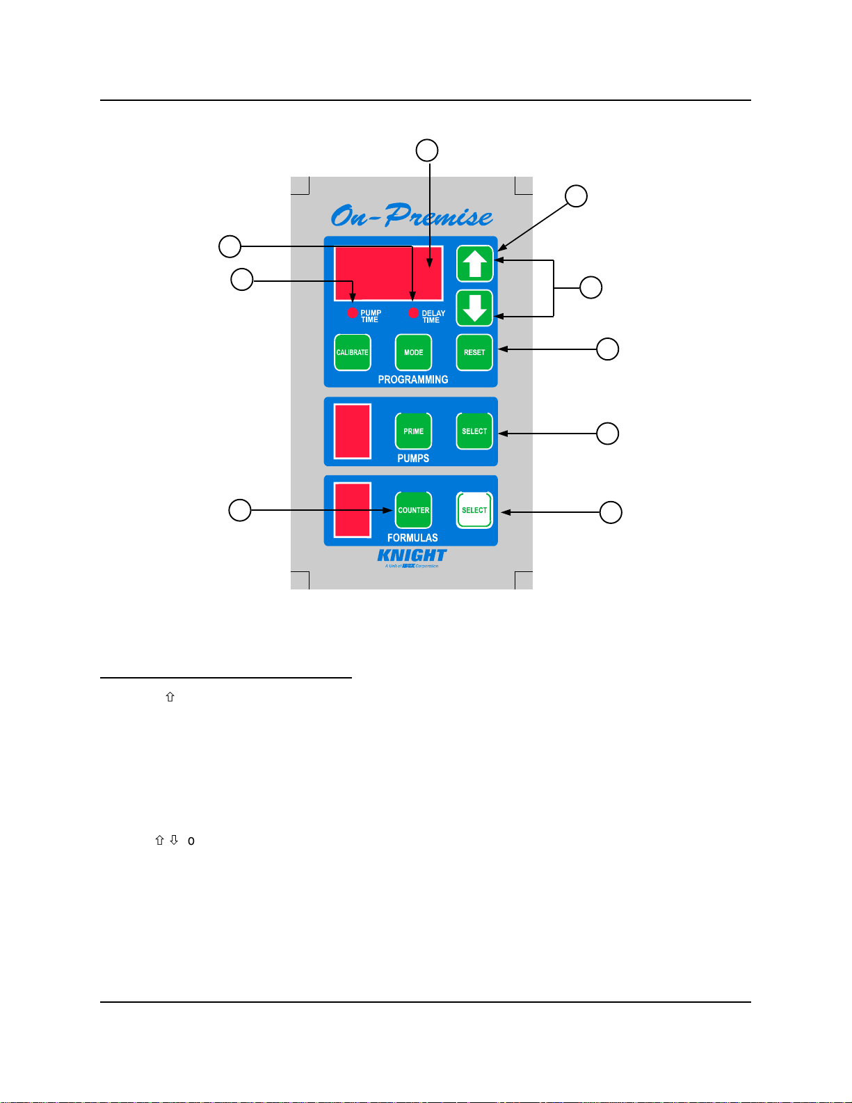
(1) Press × once (for 000 access code).
(2) The display will flash briefly and pump time LED will be lit. You now have access.
(3) Pump time LED will stay lit.
(4) Press pump SELECT until desired pump number is displayed.
NOTE: If using flush manifold, program pump “F” on all formulas to set flush time.
(5) Press formula SELECT until desired formula number appears.
(6) Use ×/Ø to input the pump time or flush time (or delay time) in seconds.
(7) To program a pump delay time, press MODE...delay time LED will be lit. Repeat steps 4 – 6.
(8) Press the counter button; the PUMP TIME/DELAY time indicators will turn off. Then use the pump
SELECT button to choose the desired pump number that will be used to count the loads for each
formula. After a few seconds the pump time LED will return indicating that your entry has been saved.
(9) Press RESET when finished programming and ready to run.
More details and complete programming information are included in the following pages.
Page 3 of 16 0901050 Rev: D (05/01)

,1752'8&7,21
35(,167$//$7,21
The OP-500 has been designed to meet today’s
laundry chemical injection needs with economy
and flexibility in mind. Through advanced
microprocessor technology, the OP-500 is one of
Knight’s least expensive laundry injectors, yet has
all of the required features to meet every type of
on-premise laundry condition. The OP-500 has
multi-formula capability for various soil conditions,
combined with independent pump run times to
provide specific volume injections. Each pump has
separately programmable delay times for all wash
formulas, which gives greater flexibility with “fixed”
timer washwheels. All programmed data is stored
in a non-volatile memory which cannot be altered
by voltage spikes or power outages. The OP-500
utilizes simple, fast programming for up to 8 pump
outputs. A separate Flush Mode function, optional
flush solenoid with case mount, and integrated
flush manifold, provide single line diluted chemical
injection to the washer. LED indicators mounted on
a remote control panel always let the user know
what is being programmed, which pump is being
signaled, and which formula is active. The signal
input circuitry will accept and verify a signal
anywhere between 24 and 240 volts.
Before connecting signal wires to the OP-500,
always check the schematic of the washwheel
controller. These schematics can be obtained in
the instruction manual of the machine or by the
machine manufacturer.
6<67(029(59,(:
The OP-500 is a two component system, with each
component performing a specific function. The
circuit board located inside the pump housing,
receives the supply signals from the washmachine.
Signals are then routed to the Remote (hand-held)
Control, which is responsible for all timing and
programming functions. Pump run times and delay
times are activated, based on what formula
number has been selected - the pumps then run
for the correct amount of time. Accessories for
installation, and other optional components, are
available for the OP-500; contact your nearest
Knight representative for details.
Before the equipment is installed, you should
survey the installation site thoroughly. At the very
least, your survey should include the following:
(1) Check to make sure that all functions of the
laundry machine are operating properly. Such
functions may include: drain valve, hot/cold
water solenoids, flush down valves, water level
switch, card reader or timer, and machine
motor.
(2) Check the proposed location for a 115, 208,or
230 VAC power source.
(3) Check the signal voltage output from the
laundry machine. Measure the voltage
between control signal and signal common,
NOT control signal and case ground.
(4) Measure the distance(s) from chemical supply
container to pump housing and from pump
housing to injection point inside the
washmachine.
,167$//$7,21
(1) Mount injector in a convenient location on a
wall near supply containers — no higher than
8’ above, and within 10’ horizontally, of supply
containers. This is usually near the
washmachine, however, dispenser can be
mounted as a remote pumping system.
(2) Mount the OP-500 Remote Control using the
stainless steel mounting bracket provided. Use
the provided mounting screws or Dual-Lock
fastening strips to secure the bracket to the
washer. If using Dual-Lock, be sure to clean
the mounting surface in preparation, as DualLock’s adhesive will not stick to a dirty surface.
The Remote Control should be mounted to the
front of the washer, near the washer control
switches where the operators can access it
easily.
(3) Ensure that the power volatage matches one
of the three available voltage connection to the
XFMR
(4) It is very important to measure the signal
voltage between the signal wire and the signal
common (NOT case ground). This
measurement must be taken when the
washmachine is operating and when products
are being called for.
0901050 Rev: D (05/01) Page 4 of 16

(5) BEFORE CONTINUING TO THE NEXT
STEP, DISCONNECT ALL ELECTRICAL
CONNECTIONS TO THE WASHMACHINE,
CARD READER (IF SO EQUIPPED), AND
INJECTOR. VERIFY THIS WITH A
VOLTMETER.
(6) Run all electrical wires through suitable
conduit. Check any applicable electrical wiring
codes
(7) Inspect wiring diagram of washmachine and
card reader (if so equipped). They are
available from the mfr. upon request.
(8) Insert one end of the suction tube into the left
side of the squeeze tube in the peristaltic
pump(s).
(9) Cut the suction tube to length and insert the
other end into the appropriate supply container
using PVC pipe as a support.
*(77,1*67$57('
One of the key features in the OP-500 system is
controlled access. A personal access code in the
OP-500 prevents unauthorized personnel from
changing run times which could result in damaged
and irreversible wash results. No timing or formula
features can be programmed without knowledge of
the access code. The code can be changed to a
number which only the programmer may know.
Each OP-500 shipped from the factory has an
access code of “000".
The OP-500 has a built-in feature to automatically
“disable” access if a pump is signaled, or if no
buttons are pressed for a few minutes, after
access has been gained. If this happens, simply
re-enter the access code and continue where you
left off. This prevents unauthorized use of the
system in the event that pressing RESET is
forgotten when done programming.
(10)Insert one end of the discharge tubing into the
right side of the squeeze tube in the peristaltic
pump(s).
(11)Form an anti-siphon loop (with the loop
pointing “down“) with the other end of the
discharge tubing and insert the end into the
supply pocket of the machine.
(12)Connect the 115, 208, or 230 VAC supply
voltage to the system.
(13)Program the system via the PROGRAMMING
instructions in this manual.
(14)Make any adjustments to programming which
can be due to product viscosity, distance
pumped, etc.
(15)Energize washmachine and card reader (if so
equipped). The system should now be
operational and service free.
63/,7&200216
For installations that require two separate
commons for supply signals, please cut and
remove resistor labeled “Split Com” located just
above common A input terminal. See wiring
diagrams (pages 12-14 ) for physical location of
resistor. Warning! Wiring two commons to the OnPremise circuit board without removing the “Split
Com” resistor will damage circuit board and void
warranty.
Entering the access code
(1) Do not access system while pumps are being
signaled from washer.
(2) If the system is new, BRIEFLY press the UP
ARROW once. If the system has had the
access code changed from the factory default
of “000" (explained later in this section) use the
UP and DOWN ARROW keys to enter the
code — after 2 seconds the display will flash to
000.
(3) If the access code was correct, the display will
show pump 1/formula 1, and the pump
SELECT button will allow the pump number to
be changed — using the pump SELECT
button can be a helpful way to determine if
access has truly been established (this can be
done at anytime during programming). If the
pump number cannot be changed, access has
not been established and this procedure
should be repeated again, starting at step 1.
NOTE: The Flush Pump will be disabled from its
typical operation until RESET is pressed. This
prevents flush activation while programming,
however, the flush pump can still be primed and
calibrated. Always press RESET when finished
programming.
Page 5 of 16 0901050 Rev: D (05/01)
 Loading...