

Knight Equipment OP-4FM Installation Manual

OP-4FM/6FM
INSTRUCTION MANUAL
INTRODUCTION
The OP (On-Premise) Flush Manifold offers an increased level of safety for operators as well as protection against
corrosion to the washer and protection against chemical burns to the fabric. When the highly corrosive laundry
chemicals are dispensed by the peristaltic pumps into the flush manifold, the unique flush mode of the control opens
the built-in water solenoid to provide a diluted flush to the washer through a single injection line. Concentrated
chemicals can now be dispensed with less chemical shock to the fabrics being washed. The built-in checkvalves
prevent back-siphoning as well as cross contamination of the chemicals.
THEORY OF OPERATION
After liquid chemicals are dispensed into the Flush Manifold assembly, water is injected into the manifold to “push”
diluted chemistry to the washer. The delivery tube is flushed clean in a post flush operation and is ready for the next
chemical. The flush mode of the OP and OP-Plus dispensers flush chemicals “with” water as they are dispensed to
the manifold and washer. Consult your dispenser programming manual for setting the flush mode.
PRE-INSTALLATION
Before mounting the manifold to the dispenser, a site survey should be performed to avoid installation problems and
to identify any items that will be needed to complete the task. You may also wish to read through the rest of this
manual to get familiar with the installation steps. Your site survey should include the following:
• Location of dispenser in relation to washer — dispenser can be located at the washer or remotely located with the
chemical supplies. The dispenser should be no more than 100’ from the washer.
• Determine proximity to water source — the water source should be as close to the dispenser as possible.
• Pressure and temperature of water source — system should operate at 20 to 40 PSI dynamic pressure. Warm or
cool water temperatures are recommended for best results.
• Backflow prevention — local codes may require vacuum breakers or other safeguards for backflow prevention.
• Discharge tubing path from manifold to washer.
• Assessment of plumbing hardware required to connect system — this will help identify what hardware is required,
based on how you choose to plumb the system.
MOUNTING THE MANIFOLD TO THE DISPENSER
The diagrams on page 3 can be used as reference for the following installation steps.
(1) Attach the two mounting brackets to the bottom of the pump case using provided screws. For retro-fitting to an
older style case, a single bracket (available from Knight) is used instead of the two end brackets.
(2) One checkvalve fitting is required for each pump that will inject into the manifold. Plugs are provided with some
manifolds to block off unused ports. Use a wrap of plumbing tape over the threads to help avoid leakage.
(3) Connect each pump’s squeeze tube directly to a port on the manifold (pull down on the output side of the tube to
create slack). Cinch a cable tie around each connection to prevent leakage.
(4) Remove label from the left side of dispenser and mount the flush solenoid using screws and nuts provided. For
6-pump applications, the solenoid mounts through the bottom of the pump case.
(5) Connect the flush solenoid wires to the terminals marked “FLUSH PUMP” on the circuit board in the OP or OP-
Plus dispenser — refer to the wiring diagram in the dispenser’s instruction manual for more information.
(6) Connect the output side of the flush solenoid to the input fitting on the manifold using the 1/4" tubing provided.
0901156 Rev: D (05/07) Page 1 of 4
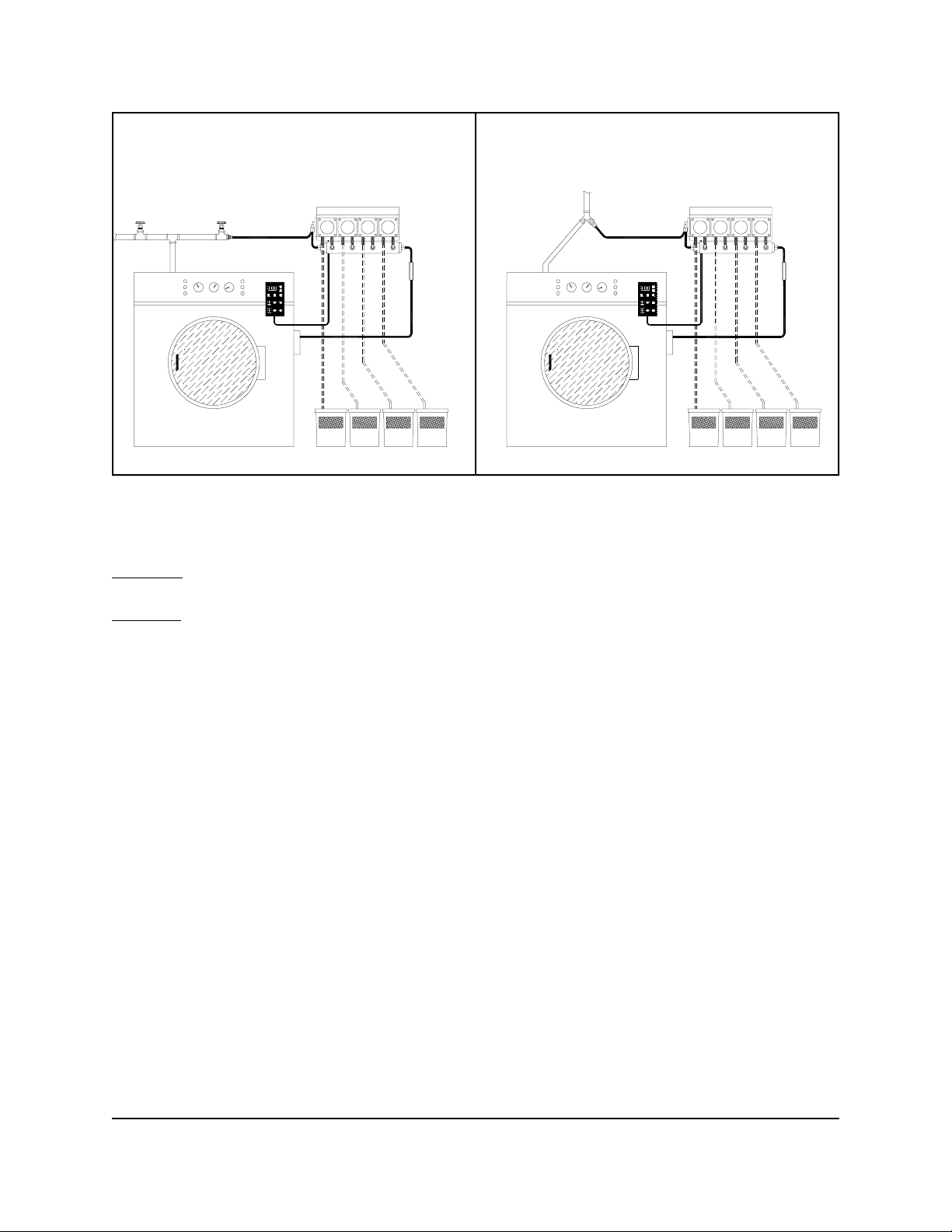
OPTION 1 OPTION 2
CONNECTING SOLENOID TO WATER SOURCE
Refer to the diagram above for illustration of the following two options.
OPTION 1:
water source, or just the water to the manifold independently.
OPTION 2:
Ball valves and a “tee” can be used to plumb into the water source. This permits shutting off the entire
Using a “Y” valve allows a single hose to feed both the solenoid, and the water inlet to the washer.
ROUTING MANIFOLD DISCHARGE TO WASHER
For best results, keep the distance between the manifold and the washer as short as possible. Avoid long vertical
climbs that may require increased water pressure and/or lengthy flush time. 1/2" ID tubing will be required, and the
connection to the barbed output fitting on the manifold should be secured with either a cable tie, or a hose clamp.
If using the optional “Flow Switch", ensure that it is connected within a few inches from the outlet of the manifold. The
switch includes barbed fittings to accommodate the 1/2" ID line. See the wiring diagram included in the dispenser’s
instruction manual for connecting the wires from the switch to the circuit board. Be sure to remove any jumper wires
or shunt jumpers from the circuit board if using the flow switch.
MAINTENANCE
Routine inspection and maintenance of the flush manifold will ensure that it continues to provide trouble-free
operation. Each time you visit the installation, check all hose and tubing connections for leaks or obstructions. In
areas that have hard water, deposits can build up inside the flush solenoid, checkvalves, and manifold. Also check
the flush line for obstructions or wear. Check that chemicals are flushing completely to the washer.
Checkvalves are like pump squeeze tubes in that they do wear over time. Checkvalves should be inspected on each
service c all to determine p roper checking act ion and positive fl ow. The checkval ve has an internal P TFE ball and
Viton seal — it is the user’s responsibility to evaluate proper compatibility of laundry products to these checkvalves.
Knight is not responsible for any damage resulting from product use or mis-use. The customer should determine a
reasonable change out interval for checkvalves to assure proper performance and prevent chemical cross
contamination or damage to lines.
Page 2 of 4 0901156 Rev: D (05/07)
 Loading...