

Page 1

CNC Series
KND—100M Computer Numerical Products
—
boring and milling machines
USER’S MANUAL
Beijing KND CNC Technique Co. Ltd.
B—99100M/01
KND LTD,1999
C
Page 2

I GENERAL
1. GENERAL
1.1 GENERAL FLOW OF OPERATION OF CNC MACHINE TOOL
1.2 NOTES ON READING THIS MANUAL
II PROGRAMMING
1. GENERAL
1.1 TOOL MOVEMENT ALONG WORKPIECE PARTS FIGURE-INTERPOLATION
1.2 FEED-FEED FUNCTION
1.3 PART DRAWING AND TOOL MOVEMENT
1.4 CUTTING FEED─SPINDLE FUNCTION
1.5 SELECTION OF TOOL USED FOR VARIOUS MACHINING-TOOL FUNCTION … 1- 7
1.6 COMMAND FOR MACHINE OPERATIONS-MISCELLANEOUS FUNCTION
1.7 PROGRAM CONFIGURATION
1.8 TOOL FIGURE AND TOOL MACHINE-TOOL LENGTH COMPENSATION
1.9 TOOL MOVEMENT RANGE -STROKE
2. CONTROLLED AXES
2.1 CONTROLLED AXES
2.2 INCREMENT SYSTEM
2.3 MAXIMUM STROKE
3. PREPARATORY FUNCTION (G FUNCTION)
4. INTERPOLATION FUNCTIONS
4.1 POSITIONING (G00)
4.2 LINEAR INTERPOLATION (G01)
4.3 CIRCULAR INTERPOLATION (G02,G03)
5. FEED FUNCTIONS
5.1 GENERAL
5.2 RAPID TRAVERSE
5.3 CUTTING FEED
5.4 DWELL (G04)
6. REFERENCE POSITION
6.1 REFERENCE POINT RETURN(G28,G29)
7. COORDINATE SYSTEM
7.1 WORKPIECE COORDINATE SYSTEM SETTING (G92)
7.2 PLANE SELECTION (G17,G18,G19)
8. COORDINATE VALUE AND DIMENSION
8.1 ABSOLUTE AND INCREMENTAL PROGRAMMING (G90, G91)
8.2 INCH/METRIC CONVERSION (G20,G21)
8.3 DECIMAL POINT PROGRAMMING
9. SPINDLE SPEED FUNCTION (S FUNCTION)
9.1 SPINDLE SPEED COMMAND
10.TOOL FUNCTION (T FUNCTION)
11. AUXILIARY FUNCTION
11.1 AUXILIARY FUNCTION (M FUNCTION)
11.2 AUXILIARY FUNCTION PARAMETER
11.3 NOTES ON AUXILIARY FUNCTION
………………………………………………………………………………
……………………………………………………………………………………
……………………
………………………………………………
………………………………………………………………………
……………………………………………………………………………………
…………………………………………………………………
……………………………………………
………………………………………………
………
…………………………………………………………
…………
…………………………………………………
………………………………………………………………………
……………………………………………………………………
……………………………………………………………………
………………………………………………………………………
………………………………………
…………………………………………………………
……………………………………………………………………
………………………………………………………
………………………………………………
………………………………………………………………………
…………………………………………………………………………………
…………………………………………………………………………
……………………………………………………………………………
……………………………………………………………………………
…………………………………………………………………
……………………………………………
…………………………………………………………………
………………………………
…………………………………………………
……………………………………………
……………………
………………………………………………
……………………………………………………
………………………………………
……………………………………………………………
………………………………………………………
……………………………………………………………………
………………………………………………
…………………………………………………
……………………………………………………
1- 0
5- 0
1- 1
1- 1
1- 1
1- 0
1- 1
……
1- 2
1- 3
1- 3
1- 7
1- 8
1- 8
1- 10
1- 11
2- 0
2- 1
2- 1
2- 1
3- 0
4- 0
4- 1
4- 1
4- 2
5- 1
5- 2
5- 3
5- 4
6- 0
6- 1
7- 1
7- 1
7- 2
8- 1
8- 1
8- 1
8- 2
9- 0
9- 1
10- 1
11- 0
11- 1
11- 3
11- 4
Page 3

12. PROGRAM CONFIGURATION
12.1 GENERAL
12.2 PROGRAM END
12.3 FILE END
…………………………………………………………………………………
……………………………………………………………………………
…………………………………………………………………………………
13. FUNCTIONS TO SIMPLIFY PROGRAMMING
13.1 CANNED CYCLE (G73,G74,G76.G80-G89)
14. COMPENSATION FUNCTION
14.1TOOL LENGTH COMPENSATION(G43,G44,G49)
14.2 CUTTER COMPENSATION B(G39,G40-G42)
14.3 CUTTER COMPENSATION C(G40-G42)
14.3.1 CUTTER COMPENSATION FUNCTION
14.3.2 OFFSET AMOUNT(H code)
14.3.3 OFFSET VECTOR
14.3.4 PLANE SELECTION AND VECTOR
14.3.5 G40,G41 and G42
14.3.6 DETAILS OF CUTTER COMPENSATION C
14.4 OFFSET AMOUNT INPUT BY PROGRAM(G10)
15. MEASURE FUNCTION
15.1SKIP FUNCTION (G31)
…………………………………………………………………
……………………………………………………………………
16. WORKPIECE COORDINATE SYSTEM SELECTION
16.1 WORKPIECE COORDINATE SYSTEM(G54-G59)
17.CUSTOM MACRO
17.1 CUSTOM MACRO COMMAND
17.2 CUSTOME MACRO BODY
17.3 CUSTOM MACRO EXAMPLES
III OPERATION
1. GENERAL
1.1 MANUAL OPERATION
1.2 TOOL MOVEMENT BY PROGRAMING-AUTOMATIC OPERATION
1.3 AUTOMATIC OPERATION
1.4 TESTING A PROGRAM
1.5 PROGRAM EDITING
1.6 DATA DISPLAY AND SETTING
1.7 DISPLAY
1.8 DATA INPUT/OUTPUT
2. OPERATOR’S PANEL
2.1 LCD/MDI PANEL
2.2 ADDITIONAL PANEL
3. POWER ON AND OFF
3.1 POWER ON
3.2 POWER OFF
4. MANUAL OPERATION
4.1 MANUAL REFERENCE POSITION RETURN
4.2 JOG FEED
4.3 INCREMENTAL FEED
…………………………………………………………………………………………
…………………………………………………………………………
………………………………………………………………………………
……………………………………………………………………
………………………………………………………………………
……………………………………………………………………………………
……………………………………………………………………
……………………………………………………………………
………………………………………………………………………
……………………………………………………………………
………………………………………………………………………
………………………………………………………………………………
………………………………………………………………………………
………………………………………………………………………
…………………………………………………………………………… …
……………………………………………………………………
…………………………………………………………
………………………………………
……………………………………………
…………………………………………………………
……………………………………
…………………………………………
………………………………………………
………………………………………
……………………………………………………
…………………………………………………………………
……………………………………………
…………………………………………………………………
……………………………………
………………………………………
……………………………
……………………………………
…………………………………………………………
………………………………………………………………
…………………………………………………………
………………………………………………………………
…………………………………………………………………
…………………………………………………………
………………………………………
17- 1
1- 0
………………
12- 1
12- 1
12- 7
12- 8
13- 1
13- 1
14- 1
14- 1
14- 4
14- 11
14- 11
14- 11
14-12
14-12
14-12
14-14
14-39
15- 1
15- 1
16- 1
16- 1
17- 1
17- 1
17- 10
1- 1
1- 1
1- 2
1- 3
1- 4
1- 6
1- 6
1- 8
1-10
2- 1
2- 1
2- 5
3- 1
3- 1
3- 1
4- 1
4- 1
4- 1
4- 3
Page 4

4.4 HANDLE FEED
4.5 MANUAL PROGRAM ZERO RETURN
4.6 MANUAL ABSOLUTE SWITCH
4.7 MANUAL AUXILIARY FUNCTION OPERATION
5. AUTOMATIC OPERATION
5.1 OPERATION MODE
5.2 START-UP
5.3 AUTO OPERATION EXECUTION
5.4 STOP
6. DRY RUN
6.1 MACHINE LOCK
6.2 AUXILIARY FUCTION LOCK
6.3 FEEDRATE OVERRIDE
6.4 RAPID TRAVERSE OVERRIDE
6.5 ANALOGUE SPINDLE OVERRIDE
6.6 DRY RUN
6.7 SINGLE BLOCK
6.8 RESTART AFTER FEEDHOLD OR STOP
6.9 OPTIONAL BLOCK SKIP
……………………………………………………………………………………
………………………………………………………………………………………
7. SAFTY OPERATION
7.1 EMERGENCY STOP
7.2 OVERTRAVEL
8. ALARM
8- 1
……………………………………………………………………………………………
9. PROGRAM STORAGE AND EDITING
9.1 PREPARATION
9.2 STORE PROGRAM IN MEMORY
9.3 STORE FILE IN MEMORY
9.4 PROGRAM SEARCH
9.5 PROGRAM DELETING
9.6 DELETING ALL PROGRAMS
9.7 PROGRAM OUTPUT
9.8 ALL PROGRAMS OUTPUT
9.9 SEQUENCE NUMBER SEARCH
9.10 PROGRAM COMPARATION
9.11 WORD INSERTING, MODIFYING AND DELETING
9.12 SEQUENCE NUMBER INSERTING AUTOMATICALLY
9.13 NUMBER OF STORED PROGRAMS
9.14 STORAGE CAPACITY
10. DATA DISPLAY AND SETTING
10.1 OFFSET AMOUNT
10.2 SET PARAMETER SETTING
10.3 CUSTOM MACRO VARIABLES DISPLAY AND SETTING
10.4 PARAMETER
10.5 PITCH ERROR COMPENSATION DATA
……………………………………………………………………………
…………………………………………………
…………………………………………………………
………………………………………
…………………………………………………………………
………………………………………………………………………
…………………………………………………………………………………
………………………………………………………
…………………………………………………………………………
……………………………………………………………
…………………………………………………………………
…………………………………………………………
……………………………………………………
…………………………………………………………………………………
……………………………………………………………………………
……………………………………………
…………………………………………………………………
…………………………………………………………………………
……………………………………………………………………
……………………………………………………………………………
……………………………………………………
……………………………………………………………………………
………………………………………………………
……………………………………………………………
……………………………………………………………………
…………………………………………………………………
……………………………………………………………
……………………………………………………………………
………………………………………………………………
………………………………………………………
…………………………………………………………
…………………………………………………
……………………………………………………………………
…………………………………………………………
………………………………………………………………………
……………………………………………………………
……………………………………………………………………………
………………………………………………
9- 3
…………………………………
……………………………
…………………………
4- 4
4- 5
4- 5
4- 7
5- 1
5- 1
5- 3
5- 3
5- 3
6- 1
6- 1
6- 1
6- 1
6- 2
6- 2
6- 3
6- 3
6- 4
6- 4
7- 1
7- 1
7- 1
9- 1
9- 1
9- 1
9- 2
9- 2
9- 3
9- 3
9- 3
9- 3
9- 4
9- 5
9- 9
9- 9
9- 9
10-1
10- 1
10- 2
10- 4
10- 5
10- 7
Page 5

10.6 DIAGNOSE
10.7 MACHINE SOFT OPERATOR’S PANEL DISPLAY AND SETTING
11. DISPLAY
11.1 STATUS DISPLAY
11.2 DATA DISPLAY
11.3 PROGRAM No. and SEQUENCE No. DISPLAY
11.4 PROGRAM MEMORY DISPLAY
11.5 COMMAND VALUE DISPLAY
11.6 POSITION DISPLAY
11.7 RUN TIME AND PARTS NUMBER
11.8 ALARM DISPLAY
11.9 INDEX CONTENT DISPLAY
12. DATA OUTPUT AND FLASH MEMORY
12.1 DATA OUTPUT
12.2 FLASH MEMORY
13. GRAPH FUNCTION
13.1 GRAPH PARAMETER SETTING
13.2 GRAPH PARAMETER
13.3 TOOL PATH
13.4 EXAMPLES
14. DESCRIPTION ON DRIVER DEVICE
14.1 UPPER LIMIT OF CUTTING FEED
14.2 RAPID TRAVERSE RATE SETTING
14.3 ELECTRIC GEAR RATIO
14.4 AC/DECELERATION TIME CONSTANT
14.5 PARAMETER SETTING
14.6 DRIVER ALARM
15. DESCRIPTION
15.1 STANDARD PARAMETER SETTING AND MEMORY CLEARING
15.2 NO CHECK ON OVERTRAVEL
15.3 BACKLASH COMPENSATION
15.4 INPUT SIGNAL FILTER
15.5 NOT ENTERED NORMAL SCREEN
15.6 ROM PARITY ALARM AND RAM CHECK
IV CONNECTION
1. SYSTEM INSTALLATION
1.1 CONFIGURATION
1.2 INSTALLATION DIMENSION
1.3 ADDITIONAL PANEL DIMENSION
2. INTERNAL CONNECTION
2.1 CONNECTION DIAGRAM
2.2 POWER OUTLET SIGNAL ARRANGEMENT
2.3 OVERRIDE SWITCH SIGNAL ARRANGEMENT
2.4 OUTLET CONNECTION BETWEEN MAIN BOARD AND EXTERNAL
…………………………………………………………………………………
………………………………………………………………………………………
…………………………………………………………………………
……………………………………………………………………………
………………………………………
…………………………………………………………
……………………………………………………………
……………………………………………………………………
………………………………………………………
…………………………………………………………………………
……………………………………………………………
……………………………………………
…………………………………………………………………………
…………………………………………………………………………
…………………………………………………………………………
………………………………………………………
……………………………………………………………………
………………………………………………………………………………
……………………………………………………………………………
……………………………………………………
………………………………………………………
……………………………………………………
…………………………………………………………………
………………………………………………
…………………………………………………………………
…………………………………………………………………………
………………………………………………………………………………
…………………………………………………………
…………………………………………………………
…………………………………………………………………
……………………………………………………
……………………………………………
…………………………………………………………………………
…………………………………………………………………………
…………………………………………………………
……………………………………………………
…………………………………………………………………
……………………………………………
………………………………………
…………………
…………………
1- 0
………………
10- 7
10- 8
11- 1
11- 1
11- 1
11- 1
11- 2
11- 2
11- 3
11- 5
11- 6
11- 6
12- 1
12- 1
12- 2
13- 1
13- 2
13- 2
13- 4
13- 4
14- 1
14- 1
14- 1
14- 1
14- 2
14- 2
14- 4
15- 1
15- 1
15- 1
15- 1
15- 1
15- 1
15- 1
1- 1
1- 2
1- 3
2- 1
2- 3
2- 3
2- 4
Page 6

3. EXTERNAL CONNECTION
3.1 EXTERNAL CONNECTION DIAGRAM
3.1.1 WITH STEPPER MOTOR
3.1.2 WITH SERVO MOTOR
3.2 INTERFACE SIGNAL FROM CNC TO DRIVER
3.2.1 INTERFACE SIGNAL LOGIC DIAGRAM
3.2.2 CONNECTOR SIGNAL
3.2.3 SIGNAL DESCRIPTION
3.2.4 CABLE MAKING
3.3 RS232-C SERIES PORT
3.4 ANALOGUE SPINDLE INTERFACE CONNECTION
3.5 ADDITIONAL PANEL CONNECTION
3.5.1 CONNECTOR SIGNAL
3.5.2 SIGNAL DESCRIPTION
3.5.3 SIGNAL CONNECTION
4. MACHINE TOOL INTERFACE
4.1 INPUT SIGNAL INTERFACE DESCRIPTION
4.1.1 INPUT SIGNAL A
4.1.2 INPUT SIGNAL B
4.2 INPUT SIGNAL INTERFACE DESCRIPTION
4.2.1 DARLINGTON OUTPUT PARAMETER
4.2.2 OUTPUT DRIVER RELAY CIRCUIT
4.2.3 OUTPUT DIRVER INDICATOR LAMP
4.3 INPUT/OUTPUT SIGNAL LIST
4.3.1 INPUT SIGNAL DIAGNOSE LIST
4.3.2 OUTPUT SIGNAL DIAGNOSE LIST
4- 5
4.3.3 OUTLET PIN SIGNAL ARRANGEMENT
4.4 INPUT/OUTPUT SIGNAL DESCRIPTION
4.4.1 INPUT SIGNAL
4.4.2 OUTPUT SIGANL
4.4.3 M code VOLTAGE LEVEL/PULSE OUTPUT DESCRIPTION
V APPENDIX
APPENDIX1 STORED PITCH ERROR COMPENSATION
APPENDIX2 G FUNCTION TABLE
APPENDIX3 RANGE OF COMMAND VALUE TABLE
APPENDIX4 BINARY AND DECIMAL CONVERSION
APPENDIX5 ALARM LIST
APPENDIX6 STATUS OF POWER-ON AND RESET
APPENDIX7 PARAMETER LIST
APPENDIX8 PLC PARAMETER LIST
APPENDIX9 OPERATION TABLE
APPENDIX10 SPECIFICATION TABLE
APPENDIX11 CNC STATUS DIAGNOSE MESSAGE
…………………………………………………………………………………
…………………………………………………………………………
…………………………………………………
………………………………………………………
…………………………………………………………
………………………………………
………………………………………
…………………………………………………………
…………………………………………………………
…………………………………………………………………
……………………………………………………………………
……………………………………………………
…………………………………………………………
…………………………………………………………
…………………………………………………………
……………………………………………
…………………………………………………………………
………………………………………………………………
…………………………………………
………………………………………
……………………………………………
…………………………………………
……………………………………………………………
………………………………………………
……………………………………………
………………………………………
………………………………………………
……………………………………………………………………
…………………………………………………………………
………………………………………………………………
…………………………………………
…………………………………………
…………………………………………
…………………………………………………………………
……………………………………………………………
…………………………………………………………………
……………………………………………………………
……………………………………………
…………………………………
4- 1
………………
1- 0
……………………………………
3- 1
3- 1
3- 2
3- 3
3- 3
3- 5
3- 6
3- 10
3- 13
3- 13
3- 14
3- 14
3- 14
3- 15
4- 1
4- 1
4- 2
4- 2
4- 3
4- 4
4- 5
4- 5
4- 6
4- 6
4- 6
4- 9
4-10
1- 1
2- 1
3- 1
4- 1
5- 1
6- 1
7- 1
8- 1
9- 1
10- 1
11- 1
Page 7

APPENDIX12 COMMUNICATION SOFTWARE DESCRIPTION
………………………………
12- 1
Page 8

Ⅰ
Ⅰ GENERAL
GENERAL -1(GENERAL) 1 - 0
Page 9
1、GENERAL
1. INTRODUCTION
GENERAL -1(GENERAL) 1 - 1
Ⅰ
KND-100M,
machines, boring machines and machining centers has been developed by Beijing KND
CNC technique Co. Ltd. to satisfy the needs of NC markets in China. The control circuit uses
high-speed microprocessors, custom LSIs, multiple-layer PCBs and high resolving power
LCD to reduce the volume in order to compact the whole system and provide high reliability.
As for control software,
control system for the first time, and increases many functions fit stepper motor according to
the character of stepper motor in order to give full play to its performance at the same time.
KND-100M
ratio.
This manual explains programming, operation, and connection. For convenience the basic
and optional specifications are explained at APPENDIX. The detailed descriptions can be
referred to as required. This manual covers everything pertaining to the system
As for the specifications for the machine operator’s panel and actual function corresponding
to different machine tools refer to the manual issued by the individual machine tool builder.
a economic CNC to control digital servo motor or stepper motor for milling
KND-100M
provides high-performance and significantly improves the performance / cost
brings overall-function CNC system to stepper motor
KND-100M.
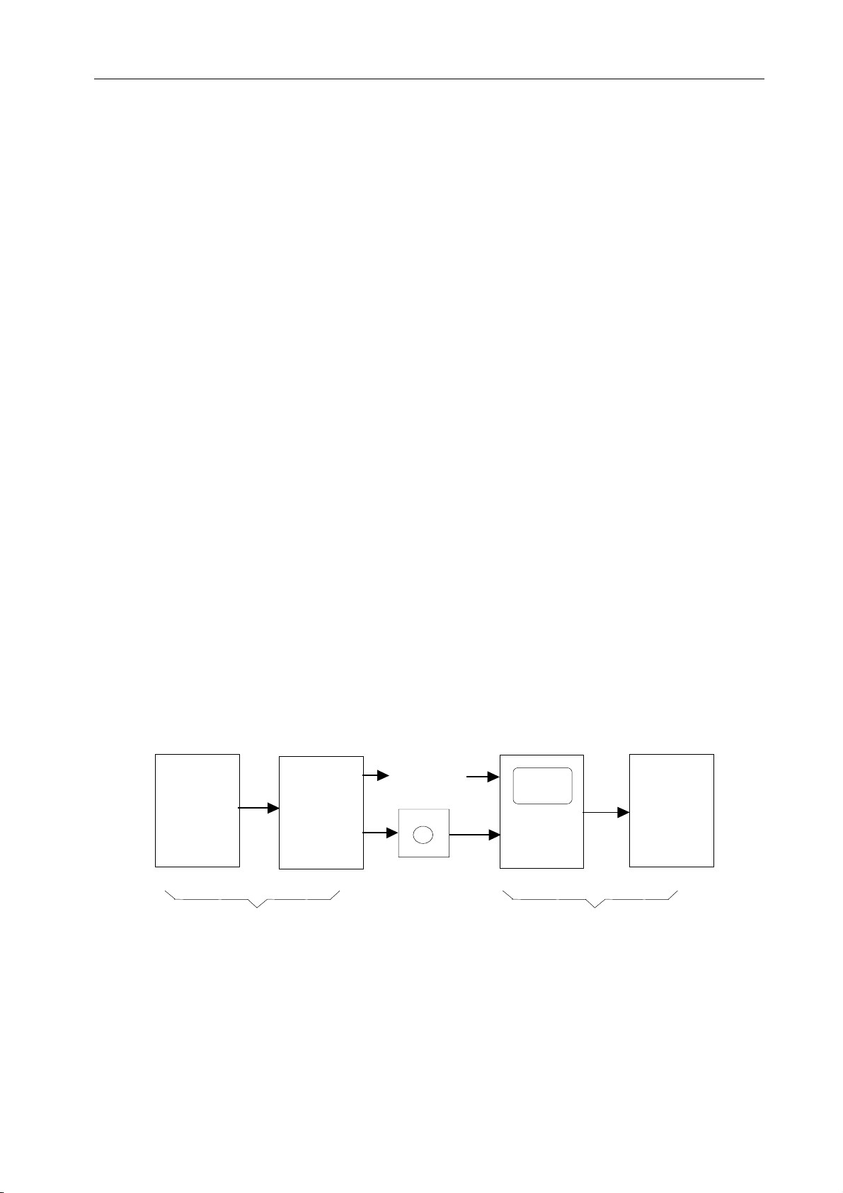
1.1 GENERAL FLOW OF OPERATION OF CNC MACHINE TOOL
When machining the part using the CNC machine tool, first prepare the program, then
operate the CNC machine by using the program.
1) First, prepare the program from a part drawing to operate the CNC machine tool. Store
the program to a media appropriate for the CNC. How to prepare the program is
described in the Chapter II. PROGRAMMING.
2) The program is to be read into the CNC system. Then, mount the workpieces and tools on
the machine, and operate the tools according to the programming. Finally, execute the
machining actually. How to operate the CNC system is described in the Chapter III.
OPERATION.
MDI/LCD
Part
drawing
Part
program
Machine
tool
CNC
Floppy disk
CHAPTER II PROGRAMMING
CHAPTE R III OPERAT ION
1.2 NOTES ON READING THIS MANUAL
1 The function of an CNC machine tool system depends not only on the CNC, but on the
combination of the machine tool, its magnetic cabinet, the servo system, the CNC, the
operator’s panels, etc. It is too difficult to describe the function, programming, and
operation relating to all combinations. This manual generally describes these from the
stand-point of the CNC. So, for details on a particular CNC machine tool, refer to the
manual issued by the machine tool builder, which should take precedence over this
manual.
Page 10

GENERAL -1(GENERAL) 1 - 2
Ⅰ
Optional
function1
. . .
Optional
function2
interface
CNC basic function
CNC system
2 This manual is
KND-100M
series CNC system common description. Under the concrete
conditions, refer to the description of individual machine tool builder.
3
KND-100M
series CNC system provide several types. Be caution to select system. For
details, refer to the order of KND Ltd.
Page 11

ⅡPROGRAMMING-1(GENERAL)
1-0
II PROGRAMMING
Page 12

1
GENERAL
ⅡPROGRAMMING-1(GENERAL)
1-1
Page 13
ⅡPROGRAMMING-1(GENERAL)
t
1.1 TOOL MOVEMENT ALONG WORKPIECE PARTS FIGUREINTERPOLATION
The tool moves along straight lines and arcs constituting the workpiece parts figure (See
II-4).
EXPLANATIONS
● Tool movement along a straight line
Program
G01 X_ _ Y_ _ ;
X_ _ ;
Workpiece
Tool
Fig.1.1 (a) Tool movement along a straight line
●Tool movement along an arc
1-2
Program
G03 X_ Y_ R_ ;
W orkpiece
Fig. 1.1 (b) Tool movement along an arc
Symbols of the programmed commands G01, G02, ... are called the preparatory function
and specify the type of interpolation conducted in the control unit.
(a) Movement along straight
line
G01 Y__;
X__Y__;
(b) Movement along arc
G03X__Y__R__;
Control u nit
interpolation
a)Move ment along
straight lin e
b) Movement along
arc
Tool
X-axis(motor)
Y-axis(motor)
Tool movemen
Fig. 1.1 (c) Interpolation function
NOTE:
Some machines move tables instead of tools but this manual assumes that tools are moved
against workpieces.
Page 14
ⅡPROGRAMMING-1(GENERAL)
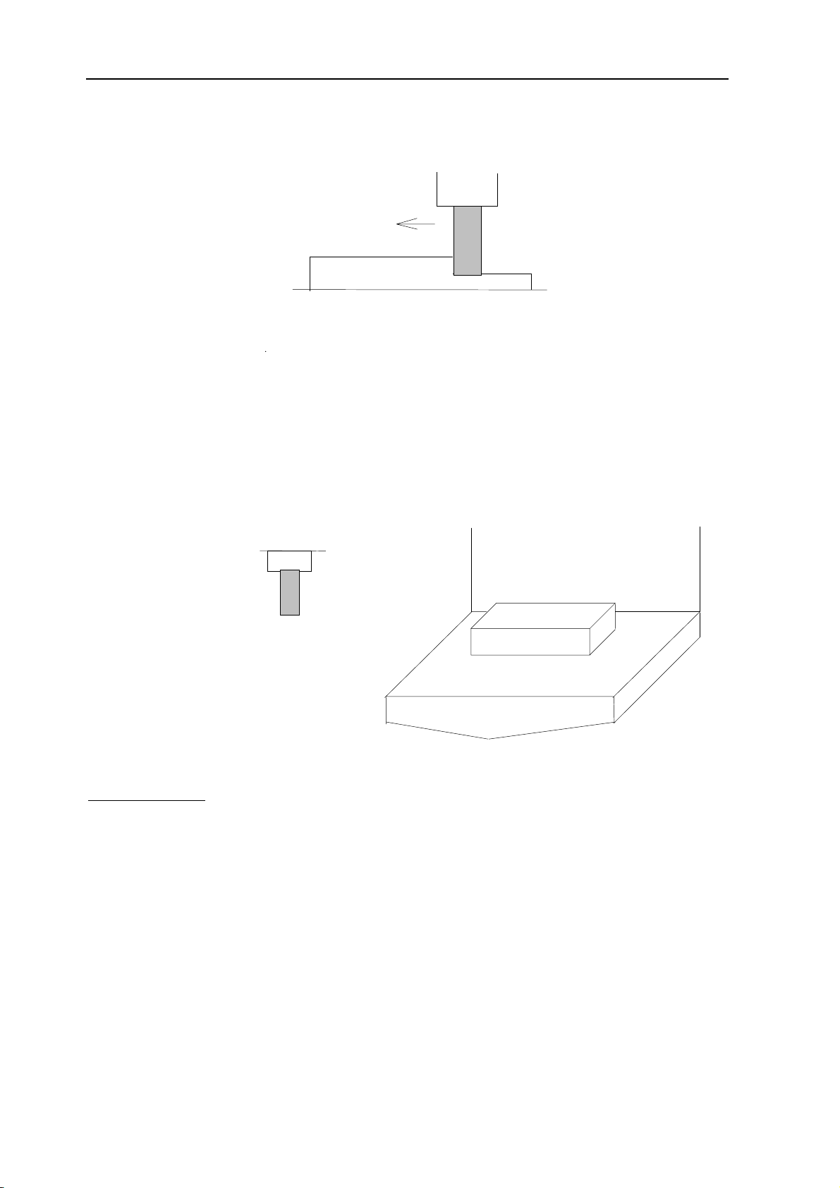
1.2 FEED- FEED FUNCTION
Movement of the tool at a specified speed for cutting a workpiece is called the feed.
1-3
F
mm/min
Workpiece
Table
Fig. 1.2 (a) Feed function
Feedrates can be specified by using actual numerics. For example, to feed the tool at a rate
of 150 mm/min, specify the following in program: F150.0
The function of deciding the feed rate is called the feed function (See II-5).
Tool
1.3 PART DRAWING AND TOOL MOVEMENT
1.3.1 Reference Position (Machine-specific position)
A CNC machine tool is provided with a fixed position. Normally, tool change and
programming of absolute zero point as described later are performed at this position. This
position is called the reference position.
Reference position
Tool
Workpiece
Fig. 1.3.1 (a) Reference position
EXPLANATIONS
The tool can be moved to the reference position in two ways:
(1) Manual reference position return (See III-1)
Reference position return is performed by manual button operation.
(2) Automatic reference position return (See II-6)
In general, manual reference position return is performed first after the power is turned
on. In order to move the tool to the reference position for tool change thereafter, the
function of automatic reference position return is used.
Table
Page 15
ⅡPROGRAMMING-1(GENERAL)
1-4
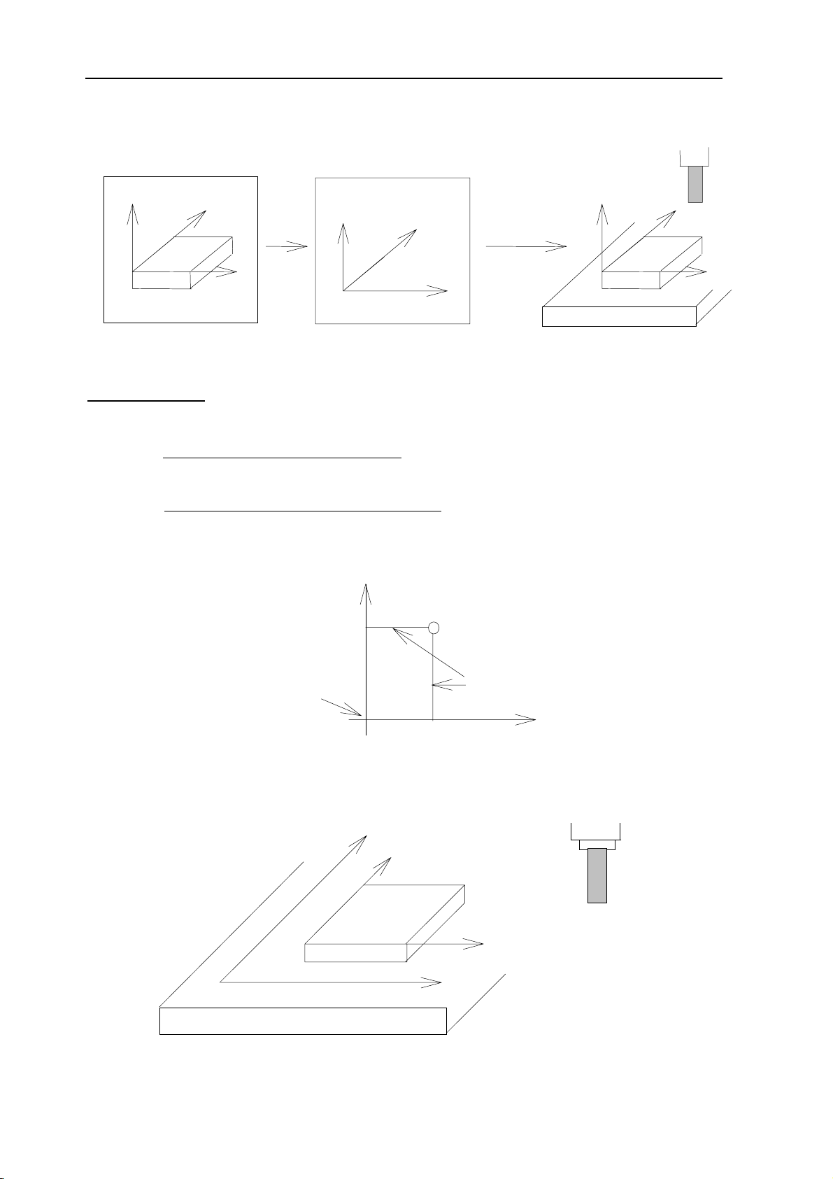
1.3.2 Coordinate System on Part Drawing and Coordinate System Specified by
CNC Coordinate System
Tool
Z
Part drawing
EXPLANATIONS
Y
Program
X
Z
Coordinate system
Fig. 1.3.2 (a) Coordinate system
Y
command
X
CNC
Z
Machine tool
● Coordinate system
The following two coordinate systems are specified at different locations: (See II-7)
(1) Coordinate system on part drawing
The coordinate system is written on the part drawing. As the program data, the
coordinate values on this coordinate system are used.
(2) Coordinate system specified by the CNC
The coordinate system is prepared on the actual machine tool table. This can be
achieved by programming the distance from the current position of the tool to the
zero point of the coordinate system to be set.
Y
workpiece
X
200
Present tool position
Program zero point
Fig. 1.3.2 (b) Coordinate system specified by the CNC
The positional relation between these two coordinate systems is determined when a
workpiece is set on the table.
300
0
Y
Distance to the zero point of a
coordinate system to be set
Tool
Y
Workpiece
Coordinat e system on part drawin g
established on the workpiece
X
Coordinat e system specified by the
CNC establ ished on the t able
X
Table
Fig. 1.3.2 (c) Coordinate system specified by CNC and coordinate system on part drawing
Page 16
ⅡPROGRAMMING-1(GENERAL)
p
The tool moves on the coordinate system specified by the CNC in accordance with the
command program generated with respect to the coordinate system on the part drawing, and
cuts a workpiece into a shape on the drawing. Therefore, in order to correctly cut the
workpiece as specified on the drawing, the two coordinate systems must be set at the same
position.
• Methods of setting the two coordinate systems in the same position
To set the two coordinate systems at the same position, simple methods shall be used
according to workpiece shape, the number of machinings.
(1) Using a standard plane and point of the workpiece.
Workpiece’s standard point
Fixed distance
Bring the tool center to the workpiece standard point. And set the coordinate system
specified by CNC at this position.
(2) Mounting a workpiece directly against the jig
Program zero point
Jig
Meet the tool center to the reference position. And set the coordinate system specified by
CNC at this position. (Jig shall be mounted on the predetermined point from the reference
position.)
(3) Mounting a workpiece on a pallet, then mounting the workpiece and pallet on the jig
pallet
1-5
Jig
Work
iece
(Jig and coordinate system shall be
specified by the same as (2)).
Page 17
ⅡPROGRAMMING-1(GENERAL)
X
A
A
1-6
1.3.3 How to Indicate Command Dimensions for Moving the Tool – Absolute,
Incremental instructions
EXPLANATIONS
Coordinate values of command for moving the tool can be indicated by absolute or
incremental designation (See II-8.1).
• Absolute coordinates
The tool moves to a point at“the distance from zero point of the coordinate system” that is to
the position of the coordinate values.
Tool
Z
(15,60,40
)
B (10,30,20)
Y
Command specifying movement from point A to point B
G90 X10.0 Y30.0 Z20.0 ;
coordinates of point B
• Incremental coordinates
Specify the distance from the previous tool position to the next tool position.
Z
30
40
Tool
10
B
Y
X
Command specifying movement from point A to point B
G91
X40.0 Y-30.0 Z-10.0 ;
Distance and direction for movement along each axis
Page 18
ⅡPROGRAMMING-1(GENERAL)
A
1.4 CUTTING SPEED – SPINDLE SPEED FUNCTION
The speed of the tool with respect to the workpiece when the workpiece is cut is called the
cutting speed. As for the CNC,
rpm unit.
the cutting speed can be specified by the spindle speed in
Tool
Diameter
RPM
1-7
V (mm/min)
Workpiece
EXAMPLES
<When a workpiece should be machined with a tool 100 mm in diameter at a cutting speed
of 80 mm/min. >
The spindle speed is approximately 250 rpm, which is obtained from N=1000v/πD. Hence
the following command is required: S250;
Commands related to the spindle speed are called the spindle speed function ( See II-9).
1.5 SELECTION OF TOOL USED FOR VARIOUS MACHINING
(TOOL FUNCTION)
When drilling, tapping, boring, milling or the like, is performed, it is necessary to select a
suitable tool. When a number is assigned to each tool and the number is specified in the
program, the corresponding tool is selected.
Tool number
01
TC magazin e
02
.
EXAMPLES
<When No.01 is assigned to drilling tool>
When the tool is stored at location 01 in the ATC magazine, the tool can be selected by
specifying T01. This is called the tool function (See II-10)
Page 19
ⅡPROGRAMMING-1(GENERAL)
1.6 COMMAND FOR MACHINE OPERATIONS –MISCELLANEOUS
FUNCTION
When machining is actually started, it is necessary to rotate the spindle, and feed coolant.
For this purpose, on-off operations of spindle motor and coolant valve should be controlled
(See II-11).
Spindle rotate
1-8
Tool
The function of specifying the on-off operations of the components of the machine is called
the miscellaneous function. In general, the function is specified by an M code. For example,
when M03 is specified, the spindle is rotated clockwise at the specified spindle speed.
coolant
Workpiece
1.7 PROGRAM CONFIGURATION
A group of commands given to the CNC for operating the machine is called the program. By
specifying the commands, the tool is moved along a straight line or an arc, or the spindle
motor is turned on and off. In the program, specify the commands in the sequence of actual
tool movements.
Fig. 1.7 (a) Program configuration
A group of commands at each step of the sequence is called the block, The program
consists of a group of blocks for a series of machining. The number for discriminating each
block is called the sequence number, and the number for discriminating each program is
called the program number (See II-12).
Program
Block
Block
Tool movement sequence
Block
Block
Block
Page 20

ⅡPROGRAMMING-1(GENERAL)
EXPLANATIONS
• Block
The block and the program have the following configurations.
NOOOO GOO XOO.O YOO.O MOO SOO TOO;
1 Block
N: Sequence number
G: Preparatory function
X,Y: Dimension word
M: Miscellaneous function
S: Spindle function
T: Tool function
; : End of block
Fig. 1.7 (b) Block configuration
A block has a sequence number at its head, which identifies the block, and an end-of-block
code at the end, indicating the end of the block. This manual indicates the end-of-block code
by ;.
• Program
Normally, a program number is specified after the end-of-block (;) code at the beginning of
the program, and a program end code (M02 or M30) is specified at the end of the program.
;
O□□□□;
M30;
Program number
Block
Block
Block
End of program
Fig. 1.7 (c) Program configuration
• Main program and subprogram
When machining of the same pattern appears at many portions of a program, a program for
the pattern is created. This is called the subprogram. On the other hand, the original program
is called the main program. When a subprogram execution command appears during
execution of the main program, commands of the subprogram are executed. When
execution of the subprogram is finished, the sequence returns to the main program.
1-9
Page 21
ⅡPROGRAMMING-1(GENERAL)
1-10
Main program subprogram#1
M98P1001
M98P1002
M98P1001
O1001
M99
subprogram#2
O1002
M99
Pole #1 Pole #1
Pole #2
Pole #2
program for
pole #1
program for
pole#2
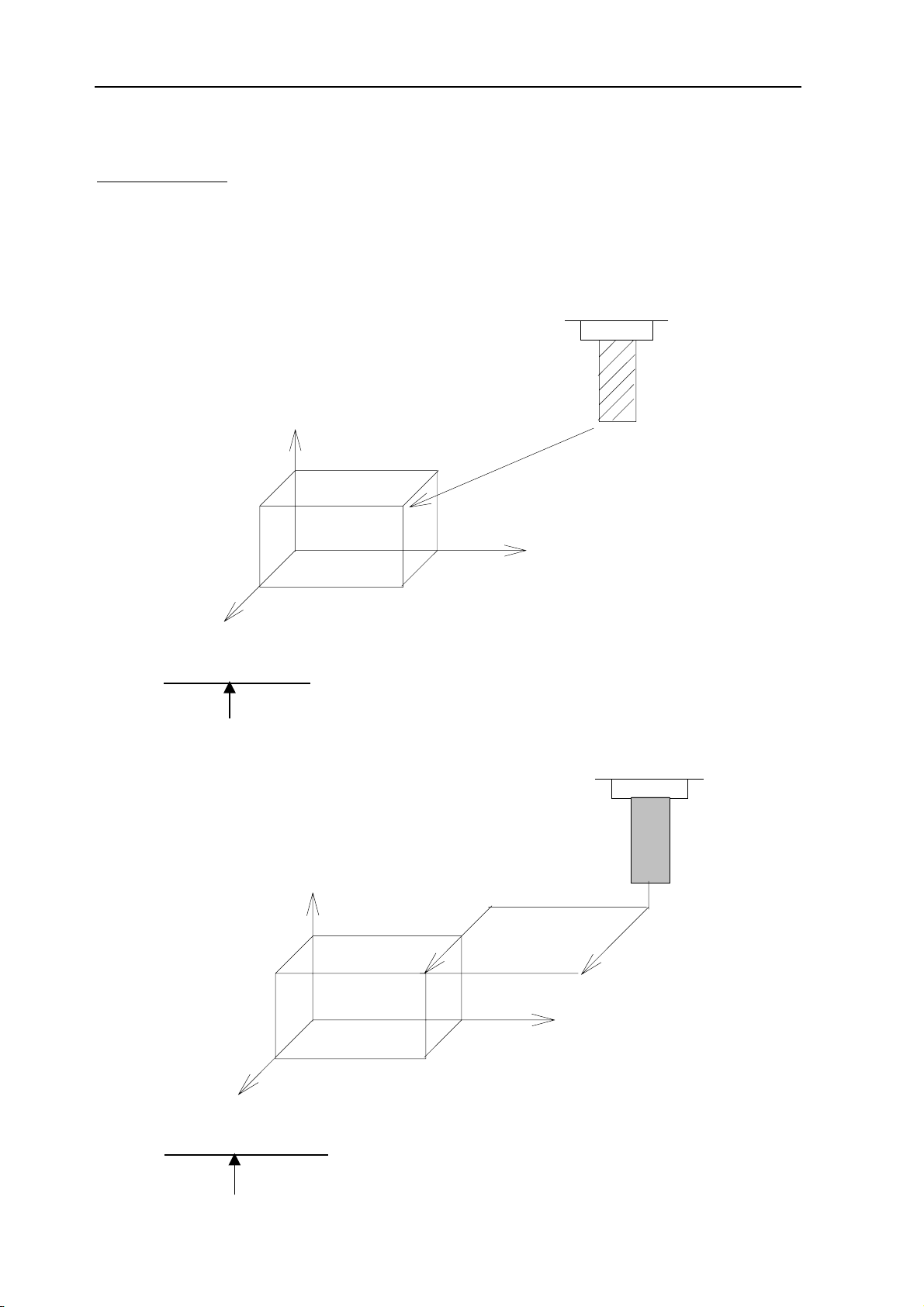
1.8 TOOL FIGURE AND TOOL MOTION BY PROGRAM
EXPLANATIONS
• Machining using the end of cutter-Tool length compensation function (See II-14.1)
Usually, several tools are used for machining one workpiece. The tools have different tool
length. It is very troublesome to change the program in accordance with the tools. Therefore,
the length of each tool used should be measured in advance. By setting the difference
between the length of the standard tool and the length of each tool in the CNC (data display
and setting: see III-11), machining can be performed without altering the program even when
the tool is changed. This function is called tool length compensation.
H2
H1
H3
H4
Workpiece
Page 22
ⅡPROGRAMMING-1(GENERAL)
• Machining using the Side of cutter-Cutter compensation function (See II-14.2)
Because a cutter has a radius, the center of the cutter path goes around the workpiece with
the cutter radius deviated.
Tool
Cutter path using cutter compensation
Machined part figure
Workpiece
1-11
If radius of cutters are stored in the CNC (Data Display and Setting : see III-11), the tool can
be moved by cutter radius apart from the machining part figure. This function is called cutter
compensation.
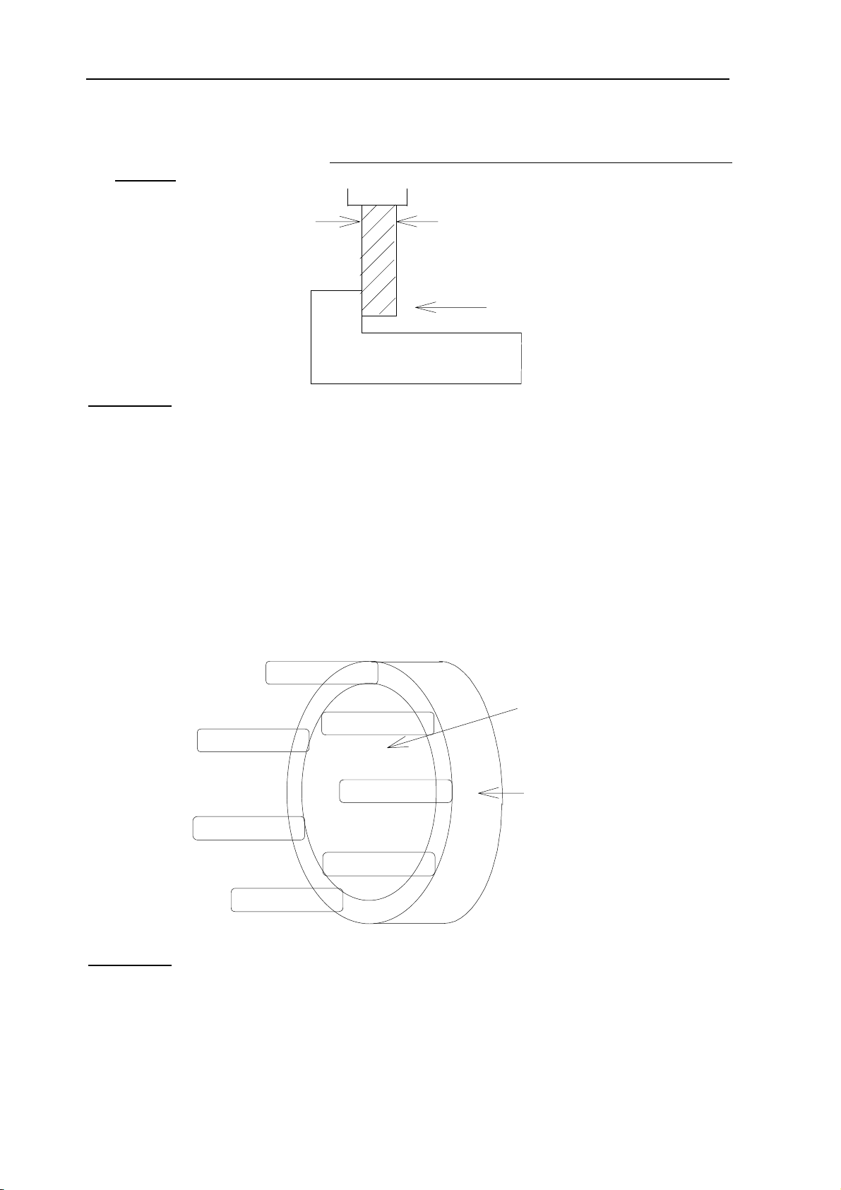
1.9 TOOL MOVEMENT RANGE-STROKE
Limit switches are installed at the ends of each axis on the machine to prevent tools from
moving beyond the ends. The range in which tools can move is called the stroke.
motor
Reference position
Table
Besides strokes defined with limit switches, the operator can define an area which the tool
cannot enter using a program or data in memory (see III-11). This function is called stroke
check.
Page 23

CONTROLLED AXES
2
ⅡPROGRAMMING-2 (CONTROLLED AXES)
2-0
Page 24

2.1 CONTROLLED AXES
f
t
Number of controlled axes 4 axes
Simultaneously controlled axes 4 axes
2.2 NAME OF AXES
ⅡPROGRAMMING-2 (CONTROLLED AXES)
2-1
Names of the three basic axes are fixed as X, Y, and Z. Names o
additional axes can be optionally selected from A, B, C, U, V, and W.
They can be set by parameter No. 008 #2, #3, #4.
2.3 INCREMENT SYSTEM
Least command increment Least input increment Maximum stroke
0.001mm 0.001mm 9999.99mm
0.0001inch 0.0001inch 999.9999inch
Combined use of the inch system and the metric system is not allowed.
There are functions that cannot be used between axes with different uni
systems (circular interpolation, cutter compensation, etc.). For the
increment system, see the machine tool builder’s manual.
2.4 MAXIMUM STROKE
Maximum stroke = Least command increment x 99999999
See 2.3 Increment System.
Page 25

PREPARATORY FUNCTION(G FUNCTION)
3
Ⅱ PROGRAMMING-3(PREPARATORY FUNCTION)
3-0
Page 26

Ⅱ PROGRAMMING-3(PREPARATORY FUNCTION)
3 PREPARATORY FUNCTION(G CODES)
A number following address G determines the meaning of the command for the
concerned block. G codes are divided into the following two types.
Type Meaning
3-1
One-shot G code
Modal G code
Example:
G01 and G00 are modal G codes in group 01.
G01X _;
Z _; G01 is effective in this range.
X _;
G00Z_ ;
The G code is effective only in the block in which it
is specified.
The G code is effective until another G code of the
same group is specified.
Explanations
1. Modal G codes have the following initial conditions when the power is turned
on or the system is reset to the clear state (bit 6 of parameter No. 045).
1) Those G codes marked* in Table 3 are specified automatically.
2) G20 and G21 retain their original conditions.
3) G00 or G01 is automatically selected according to parameter setting.
2. The G codes of group 00, are one-shot G codes.
3. If a G code that does not appear in the G code list is specified, or a G code
whose options are not supported is specified, alarm No. 010 is displayed.
4. Multiple G codes of different groups can be specified in a single block. When
multiple G codes of one group are specified in a block, the G code specified
last is effective.
5. If any G code of group 01 is specified in a canned cycle mode, the canned
cycle is automatically cancelled and the G80 condition is entered. However, a
G code of group 01 is not affected by any of the canned cycle G codes.
6. A G code is displayed from each group.
Page 27

Ⅱ PROGRAMMING-3(PREPARATORY FUNCTION)
3-2
Table 3 G code list(1/2)
G code
G00
*G01
Group Function
Positioning
Linear interpolation
01
G02
G03
Circular interpolation CW
Circular interpolation CCW
G04 Dwell, Exact stop
00
G10
Offset value setting
*G17 XY plane selection
G18
G19
02
ZX plane selection
YZ plane selection
G20 Input in inch
06
G21
G27
Input in mm
Reference position return check
G28 Return to reference position
G29 Return from reference position
00
G31
G39
*G40
G41 Cutter compensation left
07
G42
G43
G44
08
*G49
*G54
G55
G56
Skip function
Corner circular interpolation
Cutter compensation cancel
Cutter compensation right
Tool length compensation + direction
Tool length compensation - direction
Tool length compensation cancel
Workpiece coordinate system 1 selection
Workpiece coordinate system 2 selection
Workpiece coordinate system 3 selection
05
G57
G58
G59
Workpiece coordinate system 4 selection
Workpiece coordinate system 5 selection
Workpiece coordinate system 6 selection
G65 00 Macro call
Page 28

Ⅱ PROGRAMMING-3(PREPARATORY FUNCTION)
3-3
Table 3 G code list(2/2)
G code
G73
G74
Group Function
Peck drilling cycle
Counter tapping cycle
G76 Fine boring cycle
*G80
G81
G82
Canned cycle cancel
Drilling cycle, spot boring cycle or external operation function
Drilling cycle or counter boring cycle
09
G83
G84
G85
Peck drilling cycle
Tapping cycle
Boring cycle
G86 Boring cycle
G87
Back boring cycle
G88 Boring cycle
G89
Boring cycle
G90 Absolute command
03
G91
Increment command
G92
G98
G99
00
10
Setting for work coordinate system
Return to initial point in canned cycle
Return to R point in canned cycle
Page 29

ⅡPROGRAMMING-4(INTERPOLATION FUNCTIONS)
INTERPOLATION FUNCTIONS
4
4-0
Page 30

ⅡPROGRAMMING-4(INTERPOLATION FUNCTIONS)
4-1
4.1 POSITIONING (G00)
The G00 command moves a tool to the position in the workpiece system
specified with an absolute or an incremental command at a rapid traverse rate.
In the absolute command, coordinate value of the end point is programmed. In
the incremental command the distance the tool moves is programmed.
Format
G00 IP _;
IP _: For an absolute command, the coordinates of an end position, and
for an incremental command, the distance of the tool moves.
Explanations
Tool path generally does not become a straight line.
on linear position
End position
NOTE:
1 The rapid traverse rate in the G00 command is set by the parameter No. 038 to
040 for each axis independently by the machine tool builder. The rapid traverse
rate cannot be specified in the address F. Feed rate specified by address F is
valid.
2 The above parameter is in 3-axis NC system. When 4-axis is selected, parameter
number is in APPENDIX 7 note2 and 3. Parameter number without special
description in this manual is in 3-axis CNC system.
Start position
4.2 LINEAR INTERPOLATION (G01)
Format
G01 IP _F_;
IP _: For an absolute command, the coordinates of an end position, and
for an incremental command, the distance of the tool moves.
F_; Speed of tool feed (Feedrate)
Explanations
A tools move along a line to the specified position at the feedrate specified in F. The
feedrate specified in F is effective until a new value is specified. It need not be
specified for each block. It is set by the parameter of No.65. The feedrate
commanded by the F code is measured along the tool path. If the F code is not
commanded, the feedrate is regarded as zero. The feedrate of each axis direction is
as follows.
G01 Xα Yβ Zγ F f
α
Feed rate of X-axis direction :
Feed rate of Y-axis direction :
Feed rate of Z-axis direction :
F
x
F
Y
F
z
=×
f=×
L
β
f
L
γ
f=×
L
Page 31

ⅡPROGRAMMING-4(INTERPOLATION FUNCTIONS)
4-2
L =
Examples:
• Linear interpolation
22
αβγ
++
G91 G01 X200.0 Y100.0 F200.0
Y
100.0
0
start position
2
End position
200.0
X
4.3 CIRCULAR INTERPOLATION (G02,G03)
The command below will move a tool along a circular arc.
arc in the X Y plane
G17
arc in the Z X plane
arc in the Y Z plane
G02 R_
X_ Y_
G03 I_ J_
G02 R_
G18
G19
Command Description
X_ Z_
G03 I_ K_
G02 R_
Y_ Z_
G03 J_ K_
F_ ;
F_ ;
F_ ;
G17 Specification of arc on XY plane
G18 Specification of arc on ZX plane
G19 Specification of arc on ZY plane
G02 Circular Interpolation Clockwise direction (CW)
G03 Circular Interpolation Counterclockwise direction (CCW)
X _ Command values of X axis or its parallel axis
Y _ Command values of Y axis or its parallel axis
Z _ Command values of Z axis or its parallel axis
I_ X axis distance from the start point to the center of an arc with sign
J_ Y axis distance from the start point to the center of an arc with sign
K_ Z axis distance from the start point to the center of an arc with sign
R_ Arc radius with sign fixed to radius designation.
F_ Feedrate along the arc
Page 32

ⅡPROGRAMMING-4(INTERPOLATION FUNCTIONS)
Explanations
Direction of the circular interpolation
•
“Clockwise”(G02) and “counter clockwise”(G03) on the XY plane (ZX plane or
YZ plane) are defined when the XY plane is viewed in the positive-to-negative
direction of the Z-axis (Y axis or X axis, respectively) in the Cartesian coordinate
system. See the figure below.
Y
G03
X
G03
Z
G03
4-3
G02
X
G17
•Distance moved on an arc
The end point of an arc is specified by address X, Y or Z, and is expressed as
an absolute or incremental value according to G90 or G91. For the incremental
value, the distance of the end point which is viewed from the start point of the
arc is specified.
•Distance from the start point to the center of arc
The arc center is specified by addresses I, J and K for the X, Y, and Z axes,
respectively. The numerical value following I, J, or K, however, is a vector
component in which the arc center is seen from the start point, and is always
specified as an incremental value irrespective of G90 and G91, as shown below.
I, J and K must be signed according to the direction.
End point(X,Y)
Start point
G02
G18
End point(Z,X)
Start point
Z
End point(Y,Z)
G02
G19
Start point
Y
center
I
I0, J0, and K0 can be omitted. When X, Y, and Z are omitted (the end point is
the same as the start point) and the center is specified with I, J and K, a 360
(circle) is specified. G02I; Command for a circle
J
center
I
center
K
J
K
•Arc radius
The distance between an arc and the center of a circle that contains the arc can
be specified using the radius, R, of the circle instead of I, J, and K. In this case,
one arc is less than 180
When an arc exceeding 180
a negative value. If X, Y, and Z are all omitted, if the end point is located at the
°, and the other is more than 180°are considered.
°is commanded, the radius must be specified with
°arc
Page 33

ⅡPROGRAMMING-4(INTERPOLATION FUNCTIONS)
t
same position as the start point and when R is used, an arc of 0 ° is
programmed G02R ; (The cutter does not move.)
EXAMPLE:
For arc (1) (less than 180°)
G91 G02 XP60.0 YP20.0 R50.0 F300.0 ;
For arc (2) (greater than 180°
G91 G02 XP60.0 YP20.0 R-50.0 F300.0 ;
R=50
End poin
1
2
4-4
Start point
R=50
•Feedrate
The feedrate in circular interpolation is equal to the feed rate specified by the F
code, and the feedrate along the arc (the tangential feedrate of the arc) is
controlled to be the specified feedrate. The error between the specified feedrate
and the actual tool feedrate is ± 2% or less. However, this feed rate is
measured along the arc after the cutter compensation is applied.
•Restrictions
If I, J, K and R addresses are specified simultaneously, the arc specified by
address R takes precedence and the other are ignored. If an axis not comprising
the specified plane is commanded, an alarm is displayed. When an arc having a
center angle close to 180° is specified using its radius R, the system may fail to
calculate the center of the arc correctly. Therefore, specify the arc with I, J and
K.
EXAMPLES:
Y
100
R50
60
40
90 120
140
R60
200
X
Page 34

ⅡPROGRAMMING-4(INTERPOLATION FUNCTIONS)
The above tool path can be programmed as follows:
(1) in absolute programming
G92 X200.0 Y40.0 Z0 ;
G90 G03 X140.0 Y100.0 I-60.0 F300.0 ;
G02 X120.0 Y60.0 I-50.0 ;
or
G92 X200.0 Y40.0 Z0
;
G90 G03 X140.0 Y100.0 R60.0 F300.0 ;
G02 X120.0 Y60.0 R50.0 ;
(2) in incremental programming
G91 G03 X-60.0 Y60.0 I-60.0 F300.0 ;
G02 X-20.0 Y-40.0 I-50.0
;
or
G91 G03 X-60.0 Y60.0 R60.0 F300.0 ;
G02 X-20.0 Y-40.0 R50.0 ;
4-5
Page 35

5
PROGRAMMING-5(FEED FUNCTION)
Ⅱ
5-0
5.1
GENERAL
Page 36

PROGRAMMING-5(FEED FUNCTION)
Ⅱ
The feed functions control the feedrate of the tool. The following two feed functions are
available:
•
Feed functions
1. Rapid traverse
When the positioning command (G00) is specified, the tool moves at a rapid traverse
feedrate set in the CNC (parameter No. 038 to 040).
2. Cutting feed
The tool moves at a programmed cutting feedrate.
•Override
Override can be applied to a rapid traverse rate or cutting feedrate using the switch on the
machine operator’s panel.
•
Automatic acceleration/ deceleration
To prevent a mechanical shock, acceleration/deceleration is automatically applied when the
tool starts and ends its movement.
Rapid traverse: Linear acceleration/deceleration (constant acceleration) (№.041~043)
Cutting feed: Exponential acceleration/deceleration (constant time constant) (№.047)
Jog feed : Exponential acceleration/deceleration (constant time constant)(№.047)
f
eedrate after interpolation
feedrate after acceleration/deceleration
5-1
CNC
command
feedrate
Pulse distri bution
interpolation)
(
Rapid traverse rate
acceleration/
deceleration
acceleration/
deceleration
driver control
driver control
steppe r motor
interpolation
acceleration/deceleration
time
TR:: Acceleration/deceleration timeconstant for rapid
(parameterNo.041, No.042, No.043)
T
R
T
R
time
Page 37

PROGRAMMING-5(FEED FUNCTION)
T
C
A
Ⅱ
cutting feed, jog feed
:Acceleration/deceleration time constant for
feedrate. (parameter047)
time
C
•Tool path in a cutting feed
If the direction of movement changes between specified blocks during cutting feed, a
rounded-corner path may result. Because of automatic acceleration and deceleration,
corners are not cut sharply. The dwell command (G04) must be inserted between the two
blocks to cut a sharp corner.
t the point, insert the dwell command
5-2
X
Z
If the dwell command is inserted, the actual tool path matches the programmed path. The
faster the feedrate and the larger the acceleration/deceleration time constant, the larger the
error at the corner. In circular interpolation, the actual arc radius is smaller than that of the
programmed arc. This error can be minimized by making the acceleration/deceleration time
constant of feedrate small.
NOTE:
The following chart shows feedrate changes between blocks of information specifying
different types of movement.
previous block
Next block
Positioning
Feed
Not moving
×: The next block is executed after commanded rate has decreased to zero.
○: The next block is executed sequentially so that the feedrate is not changed by very much.
Positioning Feed Not moving
× × ×
× ○ ×
× × ×
Programmed path
Tool path
5.2 RAPID TRAVERSE
Format
G00 IP_ ;
G00 : G code (group 01) for positioning (rapid traverse)
IP_ ; Dimension word for the end point
Explanations
The positioning command (G00) positions the tool by rapid traverse. In rapid traverse, the
Page 38

PROGRAMMING-5(FEED FUNCTION)
A
Ⅱ
next block is executed after the specified feedrate becomes 0 and the servo motor reaches
a certain range set by the machine tool builder (in-position check). (In-position check can be
disabled for each block by setting bit 5 of parameter No. 020 to 1.) A rapid traverse rate is
set for each axis by parameter No. 038to 040, so no rapid traverse feedrate need be
programmed.
The following overrides can be applied to a rapid traverse rate with the switch on the
machine operator’s panel:
F0, 25, 50, 100%
F0: Allows a fixed feedrate to be set for each axis by parameter No. 051
For detailed information, refer to the appropriate manual of the machine tool builder.
5.3 CUTTING FEED
Feedrate of linear interpolation (G01), circular interpolation (G02, G03), etc. re commanded
with numbers after the F code. In cutting feed, the next block is executed so that the
feedrate change from the previous block is minimized.
EXPLANATIONS
•Tangential speed constant control
Cutting feed is controlled so that the tangential feedrate is always set at a specified feedrate.
X
F
End point
X
Start point
F
X
F
Z
F
5-3
F
X
Start point
F
Z
Linear interpolation
Z
rc interpolation
End point
Z
Tangential feedrate (F)
F: tangential feedrate
2
X FFF +=
2
Z
FX: X-axis feedrate
FZ: Z-axis feedrate
• Cutting feedrate clamp
A common upper limit can be set on the cutting feedrate along each axis with parameter No.
045. If an actual cutting feedrate (with an override applied) exceeds a specified upper limit, it
is clamped to the upper limit. An upper limit is set in mm/min or inch/min. CNC calculation
may involve a feedrate error of ±2% with respect to a specified value. However, this is not
true for acceleration/deceleration. To be more specific, this error is calculated with respect to
a measurement on the time the tool takes to move 500 mm or more during the steady state.
• Feedrate override
Feedrate can be overridden by a switch located on operator’s panel, from 0 to 150% (step
10%).
5.4 DWELL (G04)
FORMAT
Dwell G04 X_ ; or G04 P_
X_ : Specify a time (decimal point permitted)
;
Page 39

PROGRAMMING-5(FEED FUNCTION)
Ⅱ
P_ : Specify a time (decimal point not permitted)
EXPLANATIONS
By specifying a dwell, the execution of the next block is delayed by the specified time.
When neither P nor X is specified, exact stop is performed.
Command value range of the dwell time (Command by X)
Command value range Dwell time unit
0.001 to 99999.999s s
Command value range of the dwell time (Command by p)
Command value range Dwell time unit
1 to 99999999 0.001s
5-4
Page 40

REFERENCE POSITION
6
PROGRAMMING-6(REFERANCE POSITION)
Ⅱ
6-0
Page 41

6.General
PROGRAMMING-6(REFERANCE POSITION)
Ⅱ
6-1
•
REFERENCE POSITION
The reference position is a fixed position on a machine tool to which the tool can easily be
moved by the reference position return function. For example, the reference position is used
as a position at which tools are automatically changed. Up to two reference positions can be
specified by setting coordinates in the machine coordinate system in parameters. The first
reference position must be the machine zero point.
Reference position
workpiece
• Reference position return and movement from the reference position
Tools are automatically moved to the reference position via an intermediate position along a
specified axis. Or, tools are automatically moved from the reference position to a specified
position via an intermediate position along a specified axis. When reference position return
is completed, the lamp for indicating the completion of return goes on.
Reference position return A→B→R R (Reference position)
Return from the reference position R→B→C
B intermediate
A (Start position for reference position return)
Reference position return and return form the reference position
C (Destination of return from the reference position)
•Reference position return check
The reference position return check (G27) is the function which checks whether the tool has
correctly returned to the reference position as specified in the program. If the tool has
correctly returned to the reference position along a specified axis, the lamp for the axis goes
on.
Page 42

PROGRAMMING-6(REFERANCE POSITION)
Ⅱ
• Reference position return
G28 IP_; Reference position return
IP: Command specifying the intermediate position (Absolute/incremental command)
6-2
•
Return from reference position
G29 IP_;
IP: Command specifying the destination of return from reference position
(Absolute/incremental command)
•Reference position return check
G27 IP_;
IP: Command specifying the reference position (Absolute/incremental command)
EXPLANATION
•
Reference position return (G28)
Positioning to the intermediate or reference positions are performed at the rapid traverse
rate of each axis. Therefore, for safety, the cutter compensation, and tool length
compensation should be cancelled before executing this command. The coordinates for the
intermediate position are stored in the CNC only for the axes for which a value is specified
in a G28 block. For the other axes, the previously specified coordinates are used.
EXAMPLE:
N1 G28 X40.0 ; Intermediate position (X40.0)
N2 G28 Y60.0 ; Intermediate position (X40.0, Y60.0)
•
Return from reference position(G29)
In general, it is commanded immediately following the G28 command or G30. For
incremental programming, the command value specifies the incremental value from the
intermediate point. Positioning to the intermediate or reference points are performed at the
rapid traverse rate of each axis. When the workpiece coordinate system is changed after
the tool reaches the reference position through the intermediate point by the G28 command,
the intermediate point also shifts to a new coordinate system. If G29 is then commanded,
the tool moves to the commanded position through the intermediate point which has been
shifted to the new coordinate system.
•Reference position return check(G27)
G27 command positions the tool at rapid traverse rate. If the tool reaches the reference
position, the reference position return lamp lights up. However, if the position reached by
the tool is not the reference position, an alarm is displayed.
RESTRICTIONS
•Status the machine lock being turned on
The lamp for indicating the completion of return does not go on when the machine lock is
turned on, even when the tool has automatically returned to the reference position. In this
case, it is not checked whether the tool has returned to the reference position even when a
G27 command is specified.
First return to the reference position after power on (without an absolute position detector)
•
When the G28 command is specified when manual return to the reference position has not
Page 43

PROGRAMMING-6(REFERANCE POSITION)
A
Ⅱ
been performed after the power has been turned on, the movement from the intermediate
point is the same as in manual return to the reference position. In this case, the tool moves
in the direction for reference position return specified in parameter ( No. 006 ZMX ZMY
ZMZ). Therefore the specified intermediate position must be a position to which reference
position return is possible.
EXAMPLES
G28G90X1000.0Y500.0 ; (Programs movement from A to B)
T1111 ; (Changing the tool at the reference position)
G29X1300.0Y200.0 ; (Programs movement from B to C)
The tool is c hanged at t he reference positi on
Y
R
Reference position
6-3
700
B
Intermediate position
500
300
300
1300
1800
C
X(mm
)
Page 44

PROGRAMMING-7(COORDINATE SYSTEM) 7 - 1
Ⅱ
7. COORDINATE SYSTEM
By teaching the CNC a desired tool position, the tool can be moved to the position. Such a
tool position is represented by coordinates in a coordinate system. Coordinates are specified
using program axes.
When three program axes, the X-axis, Y-axis, and Z-axis, are used, coordinates are
specified as follows:
X_Y_Z__
This command is referred to as a dimension word
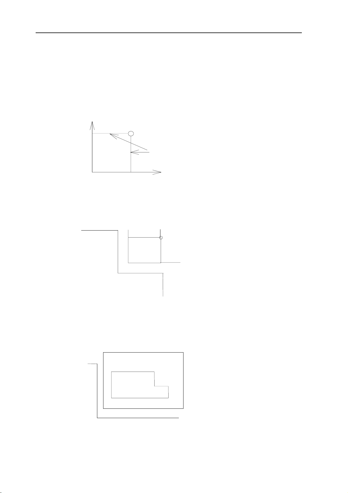
Z
20.0
30.0
40.0
.
Coordinates are specified in one of following three coordinate systems:
(1)Machine coordinate system
(2)Workpiece coordinate system
(3)Local coordinate system
The number of the axes of a coordinate system varies from one machine to another. So, in
this manual, a dimension word is represented as IP_.
X
Tool Position Specified by X40.0Y50.0Z25.0
Y
7.1 WORKPIECE COORDINATE SYSTEM
A coordinate system used for machining a workpiece is referred to as a workpiece
coordinate system. A workpiece coordinate system is to be set with the NC beforehand
(setting a workpiece coordinate system). A machining program sets a workpiece coordinate
system (selecting a workpiece coordinate system). A set workpiece coordinate system can
be changed by shifting its origin (changing a workpiece coordinate system).
7.2.1 Setting a Workpiece Coordinate System
A workpiece coordinate system can be set using one of three methods:
(1)
Method using G92
A workpiece coordinate system is set by specifying a value after G92 in the program.
(2)
Automatic setting
If bit APRS of parameter No. 012 is set beforehand, a workpiece coordinate system is
automatically set when manual reference position return is performed.
(3)
Input using the CRT/MDI panel
Six workpiece coordinate systems can be set beforehand using the CRT/MDI panel.
To use absolute programming, establish a workpiece coordinate system by applying one of
the methods described above.
FORMAT
•
Page 45

PROGRAMMING-7(COORDINATE SYSTEM) 7 - 2
Ⅱ
Setting a workpiece coordinate system by G92
G92 _ IP;
EXPLANATIONS
A workpiece coordinate system is set so that a point on the tool, such as the tool tip, is at
specified coordinates. If a coordinate system is set using G92 during tool length offset, a
coordinate system in which the position before offset matches the position specified in G92
is set. Cutter compensation is cancelled temporarily with G92.
Z
tool
Setting the coordinate system by the
23.0
G92X25.2Z23.0; comm and
(The tool tip is the start point f or the
program.)
X
25.3
G92 X25.3 Z23.0
Z
Base point
1200
600
*
Setting the coordinate system by the G92
command (The base point on the tool holder is
the start point for the program.) If an absolute
command is issued, the base point moves to the
commanded position. In order to move the tool
tip to the commanded position, the difference
from the tool tip to the base point is
compensated by tool length offset.
X
G92X600.0Z1200.0;
7.2 PLANE SELECTION
Select the planes for circular interpolation, cutter compensation, and drilling by G-code. The
following table lists G-codes and the planes selected by them.
EXPLANATIONS
Plane selected by G code
G code Selected plane X Y Z
G17 X Y plane
G18 Z X plane
G19 Y Z plane
X, Y, Z are determined by the axis address appeared in the block in which G17, G18 or G19
X-axis or an axis
parallel to it
y-axis or an axis
parallel to it
z-axis or an axis
parallel to it
Page 46

PROGRAMMING-7(COORDINATE SYSTEM) 7 - 3
Ⅱ
is commanded. When an axis address is omitted in G17, G18 or G19 block, it is assumed
that the addresses of basic three axes are omitted.The plane is unchanged in the block in
which G17, G18 or G19 is not commanded.
EXAMPLES
G17 X_Y_; XY plane,
G18 X_Z_ ; ZX plane
X_Y_; Plane is unchanged (ZX plane)
G17 XY plane
G18 ZX plane
G18 Y_ ; ZX plane, Y axis moves regardless without any relation to the plane.
NOTE:
When the system is turned on or placed in the clear state by a reset, G17, G18 or G19 is
selected according to the setting parameter.
Page 47

PROGRAMMING-8(COORDINATE AND DIMENSION
Ⅱ
8. COORDINATE VALUE AND DIMENSION
) 8 - 1
8.1
ABSOLUTE AND INCREMENTAL PROGRAMMING (G90, G91)
There are two ways to command travels of the tool; the absolute command, and the
incremental command. In the absolute command, coordinate value of the end position is
programmed; in the incremental command, move distance of the position itself is
programmed. G90 and G91 are used to command absolute or incremental command,
respectively.
FORMAT
G90 IP _ ; Absolute command
G91 IP_ ; Incremental command
EXAMPLES
Y
End point
70.0
30.0
Start point
40.0
G90 X40.0 Y70.0 ; Absolute command
G91 X-60.0 Y40.0 ; Incremental command
8.2 INCH/METRIC CONVERSION(G20,G21)
Either inch or metric input can be selected by G code.
unit G code Least command increment
inch G20 0.0001inch
metric G21 0.001 mm
This G code must be specified in an independent block before setting the coordinate
system at the beginning of the program. After the G code for inch/metric conversion is
specified, the unit of input data is switched to the least inch or metric input increment of
increment system. The unit of data input for degrees remains unchanged. The unit
systems for the following values are changed after inch/metric conversion:
(1) Feedrate commanded by F code
(2) Positional command
(3) Work zero point offset value
(4) Unit of scale for manual pulse generator
(5) Movement distance in incremental feed
(6) Some parameters
When the power is turned on, the G code is the same as that held before the power was
turn off.
100.0
X
Page 48

PROGRAMMING-8(COORDINATE AND DIMENSION
Ⅱ
WARNING
1 G20 and G21 must not be switched during a program.
2 When switching inch input (G20) to metric input (G21) and vice versa, the tool
compensation value must be reset according to the least input increment.
NOTE
1 When the least input increment and the least command increment systems are
different, the maximum error is half of the least command increment. This error is not
accumulated.
2 The inch and metric input can also be switched using settings.
8.3 DECIMAL POINT PROGRAMMING
Numerical values can be entered with a decimal point. A decimal point can be used
when entering a distance, time, or speed. Decimal points can be specified with the
following addresses: X, Y, Z, I, J, K, Q, R, and F
EXAMPLES:
Program command
Pocket calculator type
decimal point programming
) 8 - 2
Standard type decimal
point programming
X1000
Command value without decimal
point
X1000.0
Command value with decimal point
NOTE
1000mm
Unit : mm
1000mm
Unit : mm
1mm
Unit : Least input
increment (0.001 mm)
1000mm
Unit : mm
1 In the dwell command, decimal point can be used with address X but not with address
P.(This is because P is also used for a sequence number.)
2 In a single block, specify a G code before entering a value. The position of decimal point
may depend on the command.
Examples:
G20; Input in inches
X1.0 G04; X1.0 is considered to be a distance and processed as X10000.
This command is equivalent to G04 X10000. The tool dwells for 10 seconds.
G04 X1.0;
Equivalent to G04 X1000. The tool dwells for one second.
3 There is great difference in values with and without the decimal point.
G21; (millimeter dimensions)
X1. X 1mm
X1 X 0.001mm
G20; (inch dimensions)
X1. X 1inch
X1 X 0.0001inch
4 Values with and without a decimal point can be specified together.
X1000 Z23.7;
X10. Z22359;
5 Fractions less than the least input increment are truncated.
Page 49

PROGRAMMING-8(COORDINATE AND DIMENSION
Ⅱ
) 8 - 3
Examples:
X1.2345; Truncated to X1.234 when the least input increment is 0.001 mm. Processed as
X1.2345 when the least input increment is 0.0001 inch.
6 When more than eight digits are specified, an alarm occurs. If a value is entered with a
decimal point, the number of digits is also checked after the value is converted to an
integer according to the least input increment.
Examples:
X1.23456789; Alarm 003 occurs because more than eight digits are specified.
X123456.7; If the least input increment is 0.001 mm, the value is converted to integer
123456700. Because the integer has more than eight digits, an alarm
occurs.
7 A decimal point is default setting or not by using parameter P013 PODI.
PODI: When the addresses that decimal points can be specified in a program haven’t
decimal point, a decimal point is conformed to exit.
X100=X100. (X100mm)
8 A decimal point is necessary or not by using parameter P014 PODI, in order to prevent a
decimal point omitting in absolute programming.
POD 0: a decimal point is optional
1: a decimal point is necessary, or an alarm occurs (No.007).
SPECIAL EXAMPLE:
1 Though F100.=F100, when parameter POD=1, a decimal point is necessary.(F100.)
2 Address Q can specify with the decimal point, when macro variables DO=1, 1. or 0.01
must be specified in address Q. If the low eight-bit of macro variables #1132 are 1, G65
H01 #1132 Q0.255
Page 50

SPINDLE SPEED FUNCTION (S FUNCTION)
9
PROGRAMMING-9(SPINDLE SPEED FUNCTION)
Ⅱ
The spindle speed can be controlled by specifying a value
following
address S.
This chapter contains the following topics.
9.1 SPECIFYING THE SPINDLE SPEED WITH A CODE
9.2 SPECIFYING THE SPINDLE SPEED VALUE DIRECTLY
(S4-DIGIT COMMAND)
9 - 0
Page 51

PROGRAMMING-9(SPINDLE SPEED FUNCTION)
Ⅱ
9.1 SPECIFYING THE SPINDLE SPEED WITH A BINARY CODE
A 2-digit S code can be specified in a block. We can provide eight-level spindle speed
function. For a description of the use of S codes, such as their execution sequence in a
block in which a spindle speed, move command, and S code are specified, see the manual
provided by the machine tool builder.
S1~S8
S code’s execution time is set by the donors No.209.
Setting value: 0~255 (128ms~32.640ms)
Setting time=setting value x 128ms
Setting time
9 - 1
S code execution start
Execute the next block
Note:
When more than S code is specified, an alarm occurs and execution stops.
02:S code error
A 2-digit S code is effective, if a 4-digit S code is specified, the last 2-digit is effective.
S code setting time’s parameter (see 11.2)
9.2 SPECIFYING THE SPINDLE SPEED VALUE DIRECTLY
(S4-DIGIT COMMAND)
The spindle speed can be specified directly by address S followed by a four-digit value
(rpm). The unit for specifying the spindle speed may vary depending on the machine tool
builder. Refer to the appropriate manual provided by the machine tool builder for details.
9.2.1 JOG MODE
1 JOGS=1, S code specifies analogue spindle speed.
2 JOGS=0, Analogue spindle speed is set by the following parameter in JOG mode.
P61/71(4-axis):power-on initial value of analogue spindle speed in JOG mode.
unit:rpm
P62/72(4-axis):incremental value or decrement of analogue spindle speed.
P56/66 is upper limit in increment.
Spindle rotates at the speed to be set by parameter after spindle start-up in Jog mode. When
pressing the spindle override key + or -, each incremental value or decrement of spindle
speed is the increment set by parameter P62/72. Manual spindle rotational speed is displayed
on the address S of POS screen in JOG mode. In other mode, spindle rotates at the speed
specified by S code.
NOTE:
1 Rotational speed specified by parameter is not spindle motor rotational speed but spindle
speed. Spindle analogue voltage is determined by spindle shift inside CNC.
2 If mode shifts between manual and non- manual, spindle speed will change during rotation.
3 Standard parameter setting: P061=100 P062=50
4 JOG mode includes jog feed, handle/step or zero return mode(machine or program zero
return).
Page 52

10
PROGRAMMING-10(TOOL FUNCTION
Ⅱ
TOOL FUNCTION (T FUNCTION)
Tool Selection function (tool exchange) is unavailable in K100M.
) 10 - 1
Page 53

AUXILIARY FUNCTION
11
PROGRAMMING-11(AUXILIARY FUNCTION)
Ⅱ
11 - 0
Page 54

11. AUXILIARY FUNCTION
The auxiliary function: miscellaneous function (M code) for specifying spindle start,
spindle stop program end, and so on, When a move command and miscellaneous
function are specified in the same block, the commands are executed in one of the
following two ways:
i) Simultaneous execution of the move command and miscellaneous function
commands.
ii) Executing miscellaneous function commands upon completion of move command
execution.
The selection of either sequence depends on the machine tool builder’s specification.
Refer to the manual issued by the machine tool builder for details.
EXAMPLES:
N1 G91 G01 X50.0 Y-50.0 M05 ;(spindle stop)
Y
50
The commands of motion and
spindle stop execute simultaneously.
PROGRAMMING-11(AUXILIARY FUNCTION)
Ⅱ
11 - 1
50
X
11.1 AUXILIARY FUNCTION (M FUNCTION)
When a two-digit numeral is specified following address M, code signal and a strobe
signal are sent to the machine. The machine uses these signals to turn on or off its
functions. Usually, only one M code can be specified in one block. Which M code
corresponds to which machine function is determined by the machine tool builder.
M code:
M03 :spindle CW
M04 :spindle CCW
M05 :spindle stop
M08 :coolant on
M09 :coolant off
M10 :clamp
M11 :unclamp
M32 :lubricant on
M33 :lubricant off
M00 :program stop
M30 :end of program
M code’s execution time can be set by diagnose №208 except M00 and M30.
Setting value: 0~255 (128ms~32.640ms)
Setting time=setting value×128 ms
Setting time
M code execution start
ext block execution start
N
Page 55

PROGRAMMING-11(AUXILIARY FUNCTION)
Ⅱ
11 - 2
Sequence diagram and setting time
Spindle CW/CCW
Stop command
T1
Interlock signal
Spindle stop
T2
Spindle brake
T3
T1: When spindle stop command (automatic or jog) sends as it is rotating, axes interlock
signal is effective at first, spindle stop signal is sent after delaying T1. (see diagnose №
214.)
T2: the delay time from sending spindle stop signal to spindle brake signal is set by
diagnose №215/216.
T3: spindle brake time is set by diagnose №217/218.
NOTE:
1. Other M code expect mentioned is specified in program, an alarm occurs and execution
stops.
01: M code error.
2. M code will be held from beginning, even if mode changed, it can’t be cancelled in
jog mode. “RESET’ is on, M code will be disabled.
EXPLANATIONS
The following M codes have special meaning.
(1) M30
① This indicates the end of the main program.
② Automatic operation is stopped and the CNC unit is reset.
③ After a block specifying the end of the program is executed, control returns to the
start of the program.
④ The number of workpiece will increase one.
(2) M00
① Automatic operation is stopped after a block containing M00 is executed.
② When the program is stopped, all existing modal information remains unchanged
as in single block operation.
③ The automatic operation can be restarted by actuating the cycle operation.
(3) M98
① This code is used to call a subprogram.
② See the subprogram section Ⅱ-12 for details .
NOTE:
1 The block following M00 and M30, is not read into the input buffer register,
2 The code and strobe signals are not sent when M98 and M99 is actuating.
External buzzer output signal:
Page 56

PROGRAMMING-11(AUXILIARY FUNCTION)
Ⅱ
11 - 3
1 When gear shift or tool exchange in manual mode is set by parameter, a block
including S code or T code actuates in automatic mode, external buzzer output signal
will be sent automatically.
T
T
4T
after advance command finishing, press “CAN” key, external buzzer output signal
stop. If “cycle start” is pressed, the next block will be executed continuously.
Parameter 012.5 = 0/1 :S code auto/manual execution.
Parameter 012.6 = 0/1 :T code auto/manual execution
.
2 External buzzer output signal will be sent automatically when an alarm occurs.
T
T
T
Canceling the alarm or pressing “CAN” key external buzzer output stops. T is set by
diagnose №219.
11.2 AUXILIARY FUNCTIONS PARAMETER
Diagnose №160~223 is memorable (using battery) PLC parameter. The user can define
them using the BCD codes under concrete conditions.
SETTING METHOD
(1)
Setting
(A) Open program protection
(B) Select the MDI mode.
(C) Press the function button [DGNOS] to display the diagnose parameter screen.
(D) Move the cursor to the item to be changed.
(E) Input a binary data and press the key INPUT, the data will be changed .
(2)
Method of cursor moving
(A) Press PAGE or CURSOR key.
(B) Using index:
P→the desired diagnostic number→INPUT.
№208: M code process time
setting unit: 128ms
setting code: 0~255
setting value: (№208+1) x 128ms
setting field: 128ms~32.768ms
№209: S code process time
setting unit: 128ms
Page 57

PROGRAMMING-11(AUXILIARY FUNCTION)
Ⅱ
11 - 4
setting code: 0~255
setting value: (№209+1) x 128ms
setting field: 128ms~32.768ms
№214: Delay time T1 from spindle stop command sending to spindle stop signal sending
setting unit: 16ms
setting code: 0~255
setting value: №214 x 16ms
setting field: 0~4.096s
№215,216: Delay time from spindle stop signal sending to spindle brake signal sending
setting unit: 16ms
setting code: 0~65535
setting value: (№216x256+№215) x 16ms
setting field: 0~1048.560s
№217,218: Spindle brake time
setting unit: 16ms
setting code: 0~65535
setting value: (№218x256+№217) x 16ms
setting field: 0~1048.560s
№219: External buzzer output signal sending time
setting unit: 32ms
setting code: 0~255
setting value: №219 x 32ms
setting field: 0~8.192s
11.3 ALARM RELATED TO AUXILIARY FUNCTIONS
The alarm related to auxiliary functions can display by external information screen. A alarm
occurs, the external information screen will display automatically, on top of it the alarm
details will display, and “ALARM” will flash at the end of the screen.
M code error.
:
01
Illegal M codes are specified in program.
02:S code error.
Illegal S codes are specified in program.
03:T code error.
Illegal T codes are specified in program.
06:M03,M04 code error.
Spindle is specified rotary CW/CCW without spindle stop while it is rotating.
07:S code is specified as spindle rotating
S code for gear shift is specified while spindle is rotating.
09:Pressing “cycle start” key after gear shift in jog mode.
(parameter P012 BIT5 SMANL=1)
10:Pressing “cycle start” key after tool exchange in jog mode.
(parameter P012 BIT6 TMANL=1)
Spindle unit alarm.
:
11
Page 58

PROGRAMMING-11(AUXILIARY FUNCTION)
Ⅱ
11 - 5
12:Pressing “CAN” and “cycle start” key after low gear in jog mode.
choose analog spindle
(
Pressing “CAN” and “cycle start” key after high gear in jog mode.
:
15
choose analog spindle
(
)
)
Page 59

PROGRAMMING-12(PROGRAM CONFIGRATION
Ⅱ
PROGRAM CONFIGRATION
12
12.1 General
12.1.1 Main program and subprogram
There are two program types, main program and subprogram. Normally, the CNC operates
according to the main program. However, when a command calling a subprogram is
encountered in the main program, control is passed to the subprogram. When a command
specifying a return to the main program is encountered in a subprogram, control is returned
to the main program.
Main program
subprogram
) 12 - 1
Instruction 1
Instruction 2
...
...
...
Follow the direction of
th e subprog r am
Instruction N
...
...
...
The CNC memory can hold up to 63 main programs and subprograms as standard. A main
program can be selected from the stored main programs to operate the machine. See
Chapter 9 in OPERATION for the methods of registering and selecting programs.
Instruction 1
Instruction 2
...
...
...
Return to main
program
(2) SUBPROGRAM
If a program contains a fixed sequence or frequently repeated pattern, such a sequence or
pattern can be stored as a subprogram in memory to simplify the program. A subprogram
can be called from the main program. A called subprogram can also call another
subprogram.
Main program
O0001;
subprogram
;
O1000
subprogram
;
O2000
M98P1000
M30;
;
M98P2000;
M99;
One-level nesting
M98P3000
M99
Two-level nesting
;
;
Page 60

PROGRAMMING-12(PROGRAM CONFIGRATION
Ⅱ
When the main program calls a subprogram, it is regarded as a one-level subprogram call.
Thus, subprogram calls can be nested up to two levels. When custom macro is chosen,
subprogram calls can be nested up to four levels. A single call command can repeatedly call
a subprogram up to 999 times.
FORMAT
● Subprogram configuration
) 12 - 2
O
;
subprogram number
(or the colon (:) optionally in the case of ISO)
.................
....................
................
...
...
...
subprogram
...................
.......... .;
M99 ;
For how to enter subprogram into memory, see Chapter 9 in OPERATION.
Subprogram end
M99 need not constitute a separate block as
indicated below.
NOTE:
For compatibility with other devices, ‘Nxxxx’ is also used as a subprogram number instead of
O(:).
● Subprogram Execution
A subprogram is executed when called by the main program or another subprogram.
A subprogram call has the following format:
M98 ○○○○ □□□□
When no repetition data is specified, the subprogram is called just once.
Subprogram number
Number of times the subprogram is to be repeated.
EXAMPLES:
★
M98 P51002 ;
This command specifies “Call the subprogram (number 1002) five times in succession.” A
subprogram call command (M98P_) can be specified in the same block as a move
command.
★
X1000 M98 P1200 ;
This example calls the subprogram (number 1200) after an X movement.
Page 61

PROGRAMMING-12(PROGRAM CONFIGRATION
Ⅱ
★
Execution sequence of subprograms called from a main program.
Main program
N0010 ......... ;
123
subprogram
O1010 ;
) 12 - 3
N0020 ......... ;
N0030 M98 P21010 ;
N0040 ......;
N0050 M98 P1010 ;
N0060 ..... ;
N1020 ...... ;
N1030 ...... ;
N1040 ..... ;
N1050 ........ ;
N1060 ...... M99 ;
A subprogram can call another subprogram in the same way as a main program calls a
subprogram.
NOTE:
1 If the subprogram number specified by address P can not be found, alarm PS 078 is
generated.
The subprogram call command ‘M98_;’ can not be input from the MDI. In this case, prepare
2
the main program in EDIT mode as follows:
Oxxxx;
M98Pxxxx;
M02;
Then execute it in the memory mode.
Notes on Subprogram Control
●
1) If P is used to specify a sequence number when a subprogram is terminated, control does
not return to the block after the calling block, but returns to the block with the sequence
number specified by P. Note, however, that P is ignored if the main program is operating in
a mode other than memory operation mode. This method consumes a longer time than the
normal return method to return to the main program.
Main program subprogram
N0010 ………………..;
N0020………………….;
N0030………………….;
N0040 M98 P1010;
N0050…………………..;
N0060………………… ;
N0070…………………..;
O1010;
N1020………………..;
N1030…………… ;
N1040……………… ;
N1050…………………;
N1060………………….;
N1070 M99 P0070;
2) If M99 is executed in a main program, control returns to the start of the main program. For
example, M99 can be executed by placing /M99 ; at an appropriate location of the main
program and setting the optional block skip function to off when executing the main
program. When M99 is executed, control returns to the start of the main program, then
execution is repeated starting at the head of the main program. Execution is repeated while
the optional block skip function is set to off. If the optional block skip function is set to on,
the /M99 ; block is skipped ; control is passed to the next block for continued execution.
Page 62

PROGRAMMING-12(PROGRAM CONFIGRATION
k
Ⅱ
) 12 - 4
If/M99Pn ; is specified, control returns not to the start of the main program, but to sequence
number n. In this case, a longer time is required to return to sequence number n.
Optional bloc
skip OFF
Main program
N0010……..…;
N0020……..…;
N0030……..…;
N0040……..…;
N0050……..…;
N0060……..…;
/N0070 M99 P0030;
N0080……..…;
N0090 M02;
Optional
block
skip ON
12.1.2 Program number
A program number consisting of address O followed by a four-digit number is assigned to
each program at the beginning registered in memory to identify the program.
O
□□□□
program number
address
O
(1~9999,
leading zero suppression
)
A program begins with a program number and ends with M30; or M99;.
12.1.3 Sequence Number and Block
A program consists of several commands. One command unit is called a block. One block is
separated from another with a“ ;” or “ *” as end of block code.
At the head of a block, a sequence number consisting of address N followed by a number not
longer than four digits (1 to 9999) can be placed.
Sequence numbers can be specified in a random order, and any numbers can be skipped.
Sequence numbers may be specified for all blocks or only for desired blocks of the program.
In general, however, it is convenient to assign sequence numbers in ascending order in phase
with the machining steps (for example, when a new tool is used by tool replacement, and
machining proceeds to a new surface with table indexing.)
NOTE:
Program number 0 cannot be used. So“0”must not be used for a sequence number regarded
as a program number.
12.1.4 Optional block skip
When a slash is specified at the head of a block, and optional block skip switch on the
machine operator panel is set to on, the information contained in the block is ignored in
memory operation.
When optional block skip switch is set to off, the information contained in the block for which
/is specified is valid. This means that the operator can determine whether to skip the block
containing.
This function is ignored when programs are loaded into memory. Blocks containing / are also
machine operator panel is set to on, the information contained in the block is ignored in
Page 63

PROGRAMMING-12(PROGRAM CONFIGRATION
Ⅱ
) 12 - 5
memory operation.
When optional block skip switch is set to off, the information contained in the block for which
/is specified is valid. This means that the operator can determine whether to skip the block
containing.
This function is ignored when programs are loaded into memory. Blocks containing / are also
stored in memory, regardless of how the optional block skip switch is set.
Programs held in memory can be output, regardless of how the optional block skip switches
are set.
Optional block skip is effective even during sequence number search operation.
The following range is ignored when the optional block skip switch is ON.
/N123 G01 X4
…………; N7890
│← range ignored → |
Example:
N100 X100.0 ;
/N101 Z100.0
N102 X200 ;
;
In the above example, the block of N101 is skipped when switch is ON.
NOTES:
(1) A slash (/) must be specified at the head of a block. If a slash is placed elsewhere, the
information from the slash to immediately before the EOB code is ignored.
(2) Optional block skip operation is processed when blocks are read from memory into a
buffer. Even if a switch is set to on after blocks are read into a buffer, the blocks already
read are not ignored.
(3) This function is also effective during a sequence number search.
(4) When storing the program in memory, this function is ineffective. A block with a slash (/) is
also stored in the memory regardless of the position of the OPTIONAL BLOCK SKIP
switch.
(5) When output the program from memory, the program is output regardless of the position of
the OPTIONAL BLOCK SKIP switch.
12.1.5 Block configuration (word and address)
A block consists of one or more words. A word consists of an address followed by a number
some digits long. (The plus sign (+) or minus sign (-) may be prefixed to a number.)
Word = Address + number (Example : X-1000)
For an address, one of the letters (A to Z) is used ; an address defines the meaning of a
number that follows the address. The following table indicates the usable addresses and their
meanings.
The same address may have different meanings, depending on the preparatory function
specification.
Page 64

PROGRAMMING-12(PROGRAM CONFIGRATION
Ⅱ
) 12 - 6
Major functions and addresses
Function Address Meaning
Program number
Sequence number
Preparatory function
Dimension word
O*
N
G
X,Y,Z
R
I,J,K
Feed function F
Spindle speed function
Tool function
Auxiliary function
Offset number
Dwell
Program number designation
S
T
M
H
P,X
P
Program number
Sequence number
Specifies a motion mode (linear, arc, etc.)
Coordinate axis move command
Arc radius
Coordinate of the arc center
Rate of feed per minute
Spindle speed
Tool number
On/off control on the machine tool
Offset number
Dwell time
Subprogram number
Number of repetition
Parameter
P
P
,Q,R
Number of subprogram repetitions
Canned cycle parameter
NOTE:
In ISO code, the colon ( : ) can also be used as the address of a program number. If an
attempt is made to execute % when M30 is not placed at the end of the program, and the
reset state is set to CNC.
12.1.6 Major addresses and ranges of command values
Major addresses and the ranges of values specified for the addresses are shown below. Note
that these figures represent limits on the CNC side, which are totally different from limits on
the machine tool side. For example, the CNC allows a tool to traverse up to about 100 m (in
millimeter input) along the X axis.
However, an actual stroke along the X axis may be limited to 2 m for a specific machine tool.
Similarly, the CNC may be able to control a cutting federate of up to 100 m/min, but the
machine tool may not allow more than 3 m/min. When developing a program, the user should
carefully read the manuals of the machine tool as well as this manual to be familiar with the
restrictions on programming.
Page 65

PROGRAMMING-12(PROGRAM CONFIGRATION
Ⅱ
Major addresses and ranges of command values
Function Address Input in mm Input in inch
) 12 - 7
Program number O
Sequence number N
Preparatory function G
Dimension word
Feed per minute F
Spindle speed function S
Tool function T
Auxiliary function M
Dwell X,P
Designation of a
program number
Repetition count
X,Y,Z,I,J,K,Q,R
P
1~9999 1~9999
1~9999 1~9999
0~99 0~99
±9999.999mm ±999.9999inch
1~15.000mm/min 0.01~600.00inch/min
0~9999 0~9999
0~99 0~99
0~99 0~99
0~9999.999s 0~9999.999s
1~9999 1~9999
Offset number H
0~32 0~32
12.2 Program end
The end of a program is indicated by commanding one of the following codes at the end of the
program:
EIA ISO Meaning usage
M30 CR M30 LF For main program
M99 CR M99 LF
If one of the program end codes is executed in program execution, the CNC terminates the
execution of the program, and the reset state is set. If M30CR or M30LF is at the end of the
program, the program will return its beginning(in AUTO mode).
When the subprogram end code is executed, control returns to the program that called the
subprogram.
For subprogram
Page 66

PROGRAMMING-12(PROGRAM CONFIGRATION
Ⅱ
12.3 File end
A file end is indicated by ER(EIA) or %(ISO) specified at the end of the program.
EIA ISO Meaning
ER % Program End
NOTE
If M30 is not at the end of the program, and
the NC will enter a reset status.
:
ER(EIA) or %(ISO) is about to be executed,
) 12 - 8
Page 67

PROGRAMMING-13(FUNCTIONS TO SIMPLIFY PROGRAMMING
Ⅱ
13. FUNCTIONS TO SIMPLIFY PROGRAMMING
13.1 Canned Cycle (G73, G74, G76, G80~89)
Canned cycles make it easier for the programmer to create programs. With a canned
cycle, a frequently-used machining operation can be specified in a single block with a G
function; without canned cycles, normally more than one block is required. In addition, the
use of canned cycles can shorten the program to save memory.
Table 13.1 (a) lists canned cycles.
G code Drilling(-Z
direction)
Operation at the
bottom of a hole
Retraction(+Z
direction)
) 13 - 1
Application
G73 Intermittent feed
G74 Cutting feed
G76 Cutting feed Spindle Orientation
G80
G81 Cutting feed
G82 Cutting feed Dwell
G83 Intermittent feed
G84 Cutting feed
G85 Cutting feed
G86 Cutting feed Spindle stop
G87 Cutting feed Spindle CW
G88 Cutting feed
G89 Cutting feed Dwell Cutting feed Boring cycle
Explanations
A canned cycle consists of a sequence of six operations (Fig. 13.1 (a))
Operation 1— Positioning of axes X and Y (including also another axis)
Operation 2— Rapid traverse up to point R level
Operation 3— Hole machining
Operation 4— Operation at the bottom of a hole
Operation 5— Retraction to point R level
Operation 6— Rapid traverse up to the initial point
──
Dwell→Spindle CW
── ── ──
──
──
Dwell→Spindle
CCW
──
Dwell→ spindle
stop
Rapid
traverse
Cutting feed
Rapid
traverse
Rapid
traverse
Rapid
traverse
Rapid
traverse
Cutting feed
Cutting feed Boring cycle
Rapid
traverse
Rapid
traverse
Manual Boring cycle
High-speed peck drilling cycle
Left-hand tapping cycle
Fine boring cycle
Cancel
Drilling cycle, spot drilling
cycle
Drilling cycle, counter boring
cycle
Peck drilling cycle
Tapping cycle
Boring cycle
Back boring cycle
Page 68

PROGRAMMING-13(FUNCTIONS TO SIMPLIFY PROGRAMMING
Ⅱ
Operation ①
nitial point level
I
) 13 - 2
Operation ②
R point level
Operation ③
Z point
Operation ⑥
Operation
Operation ④
⑤
Fig. 13.1 (a) Canned cycle operation sequence
Positioning is performed on the XY plane and drilling is performed on the Z axis. Positioning
and drilling cannot be performed on any other than this plane and axis combination, this is
indifferent to the plane selection G command. Three canned cycle operations, to be more
strict, consists of these three modes, each of which are specified in a particular modal G
code, as shown below.
1) Data format
G90 Absolute;
G91 Incremental.
2) Return point level
G98 Initial point level;
G99 R point level.
3) Drilling mode
G73, G74, G76, G80~89
NOTE:
The initial level means the absolute value of the Z-axis at the time of changing from the
canned cycle cancel mode into the canned cycle mode.
(A) The travel distance along the drilling axis varies for G90 and G91 as follows:
G90 G91
Z=0
R
Point R
Point Z
Absolute mode
Z
Point R
Point Z
Incremental mode
Fig.13.1 (B) Absolute and Incremental programming
R
Z
Page 69

PROGRAMMING-13(FUNCTIONS TO SIMPLIFY PROGRAMMING
Ⅱ
) 13 - 3
(B) When the tool reaches the bottom of a hole, the tool may be returned to point R or to the
initial level. These operations are specified with G98 and G99. The following illustrates
how the tool moves when G98 or G99 is specified. Generally, G99 is used for the first
drilling operation and G98 is used for the last drilling operation. The initial level does not
change even when drilling is performed in the G99 mode.
return to the initial level
G98 (
Initial level
) G99 (
return to point R
Initial level
R point level
)
Fig.13.1 (C) Initial point level and R point level
Data related to drilling operation specified subsequent to these G73,G74,G76,G81 to
(C)
G89, G98 and G99 constitute one block. This command permits the data to be stored in
the control unit as a modal value. The data related to drilling operation is commanded as
follows:
G○○ X_ _Y_ _ Z_ _R_ _Q_ _P_ _F_ _;
Hole machining data
Hole positioning data
Hole machining mode
Page 70

PROGRAMMING-13(FUNCTIONS TO SIMPLIFY PROGRAMMING
Ⅱ
Specified command address specification
Hole machining mode G Refer to table 13.1
Specifies the hole position by an absolute or
Hole positioning data
X,Y
incremental value. The control mode is the same as
positioning G00.
Specifies the distance from point R to the hole bottom in
increment or the coordinate values of the hole bottom in
Z
absolute. Feed rate in operation 3 depends on the F
code. Feed rate in operation 5 depends on the drilling
mode. (G73,G74,G76,G81 to G89).
R indicates a distance from the initial point to point R in
Hole machining data
R
increment, or the coordinate values of R point position
in absolute. Feed rate in operation 2 and 6 is rapid
traverse.
Q
Specifies a depth of cut at each time in G73 or G83
mode, and shift value in G76 or G87 mode (this is
always in incremental value).
P
Specifies a dwell time in the hole bottom position.
Relation between actual dwell time and command value
accords with a G04 command.
F Specifies a feed rate in cutting feed.
) 13 - 4
Because the hole machining mode (G○○), if once specified, does not change until other
hole machining mode is specified or until the canned cycle canceling G code is specified, it
is not required to specify the hole machining mode in each block to execute the same hole
machining. The canned cycle canceling G codes are G80 and G codes in the 01 group.
The hole machining data, once specified, remains unchanged until the data is altered or the
canned cycle is cancelled. Accordingly, specify all the required hole machining data when
starting the hole machining and specify the altered data, if necessary, during canned cycle.
NOTE:
1 The cutting feed specified by F code is always valid regardless of canceling the canned
cycle.
2 When press the “RESET” key in canned cycle, all commanded data will be erased.
EXAMPLES:
Sequence
① G00 X-M3 ;
② G81 X- Y- Z- R- F-; Initial data of canned cycle parameter “Z,R,F” must be
③ Y-; As drilling mode and drilling data are same as in program
④ G82 X- P-; After the positioning motion specified by the address X, the drilling
specified data
description
specified.
②, G81 Z,R and F can be neglected. After the positioning
motion specified by the address Y, the drilling is executed
by G81mode.
Page 71

PROGRAMMING-13(FUNCTIONS TO SIMPLIFY PROGRAMMING
Ⅱ
) 13 - 5
is executed by G82 mode. At this time, the drilling data used are
as follows.
Z,R and F …………………………….specified in the block ②
⑤
G80 X- Y- M5 ;
P………………………………………… specified in the block ④
The drilling motion is not performed. All drilling data except F is
cancelled.
⑥ G85 X- Z- R- P-; The address Z and R must be specified because these data have
been cancelled in block ⑤. The F code is the same as that in block
②, and is omitted. The address P is not required in this block but is
stored.
⑦
X- Z- ;
After the positioning motion specified by the address X and Z, the
drilling is executed. At this time, the drilling data used are as follows.
Z…………… …………………………….specified in the block ⑦
P………………………………………… specified in the block ⑥
F………………………………………… specified in the block ②
⑧ G89 X- Y-; After the positioning motion specified by the address X and Y, the
drilling is executed in G89 mode. At this time, the drilling data used
are as follows.
Z…………… …………………………….specified in the block ⑦
⑨
G01 X- Y- ;
R,P… ………………………………… specified in the block ⑥
F………………………………………… specified in the block ②
The hole machining mode and the hole machining data are
cancelled.
Each machining mode is described in the followings.
(1) G73 (High-speed Peck Drilling Cycle )
Page 72

PROGRAMMING-13(FUNCTIONS TO SIMPLIFY PROGRAMMING
Ⅱ
) 13 - 6
G73 (G98) G73 (G99)
Point R
Initial level
q
d
q
q
Point Z
Point R
q
d
q
q
Point Z
The “d” value is set by a parameter (№.049/058). Highly efficient hole machining can be
performed, making removal of chips easier and keeping relief motions to a minimum. The
relief motion is effected at the rapid traverse rate.
(2) G74 Left-handed Tapping Cycle
G74 (G98) G74 (G99)
Point R
Spindle CW
P
Initial level
Spindle CCW
Point R
Spindle CW
Point Z
P
Point Z
Spindle CCW
This command specifies the spindle to rotate clockwise at the hole bottom, and then a lefthanded tapping cycle to be performed.
NOTE:
During tapping by G74, feed rate override is ignored and the motion doesn’t stop until
completion of the cycle even if the feed hold is effected.
(3) G76 (FINE BORNING CYCLE)
G76 (G98) G76 (G99)
Page 73

PROGRAMMING-13(FUNCTIONS TO SIMPLIFY PROGRAMMING
)
Ⅱ
) 13 - 7
Point R
Spindle
orientation
Spindle orientation
Spindle CW
P
Dwell
Shift (rapid traverse
tool
q
Initial level
Point R
Spindle
orientation
Point Z
When the bottom of the hole has been reached, the
spindle is stopped at the fixed rotation position, and the
Spindle CW
q
P
Shift (rapid traverse)
Point Z
dwell
tool is moved in the direction opposite to the tool tip and
retracted. This ensures that the machined surface is not
damaged and enables precise and efficient boring to be
performed.
Shift amount q
NOTE:
Be sure to specify a positive value in Q. If Q is specified with a negative value, the sign is
ignored. Set the direction of shift in parameter №.005 PMXY . Q (shift at the bottom of a hole)
is a modal value retained within canned cycles. It must be specified carefully because it is
also used as the depth of cut for G73 and G83.
(4) G80 Canned Cycle Cancel
All canned cycles are canceled to perform normal operation. Point R and point Z are cleared.
This means that R = 0 and Z = 0 in incremental mode. Other drilling data is also canceled
(cleared).
(5) G81 Drilling Cycle, Spot Drilling
G81 (G98) G81 (G99)
Initial level
Point R
Point Z
(6) G82 Drilling Cycle, Counter Boring Cycle)
Point R
Point Z
Page 74

PROGRAMMING-13(FUNCTIONS TO SIMPLIFY PROGRAMMING
Ⅱ
G82 (G98) G82 (G99)
) 13 - 8
P
Dwell
Point R
Point Z
Initial level
Dwell
P
Point R
Point Z
This command is equal to G81 except that the tool moves up after dwell is performed at the
bottom (specifies the dwell time with an address P). Since dwell is performed at the bottom
of the hole, the precision of the hole depth is improved.
(7) G83 Peck Drilling Cycle
G83 (G98) G83 (G99)
Point R
Initial level
q
q
q
d
Point Z
Point R
q
q
q
Point Z
d
G83 X- Y- Z- Q- R- F-;
Q represents the depth of cut for each cutting feed. It must always be specified as an
incremental value. In the second and subsequent cutting feeds, rapid traverse changes to
cutting feed at the distance “d” mm above the position where the immediately proceeding cut
ended. Specify the amount of retraction in parameter №.050/059. Be sure to specify a
positive value in Q. Negative values are ignored.
(8) G84 Tapping Cycle
Page 75

PROGRAMMING-13(FUNCTIONS TO SIMPLIFY PROGRAMMING
Ⅱ
G84 (G98) G84 (G99)
) 13 - 9
Point R
P
Dwell
Spindle CCW
Point Z
Initial level
Spindle CW
P
dwell
Point Z
P
Dwell
Spindle CCW
Point Z
Spindle CW
P
Dwell
This command specifies that the spindle rotates in the counterclockwise direction at the hole
bottom, and a tapping cycle is performed.
NOTE:
Feedrate overrides are ignored during tapping. A feed hold does not stop the machine until
the return operation is completed.
(9) G85 Boring Cycle
G85 (G98) G85 (G99)
Point R
Initial level
Point Z
Point R
Point Z
This command is equal to G84 except that the spindle does not reverse at the hole bottom.
(10) G86 Boring Cycle
Page 76

PROGRAMMING-13(FUNCTIONS TO SIMPLIFY PROGRAMMING
Ⅱ
G86 (G98) G86 (G99)
) 13 - 10
Point R
Spindle stop
Point Z
Spindle CW
Initial level
Spindle CCW
R 点
Initial level
Spindle CW
Point Z
This command is equal to G81 except that the spindle stops at the hole bottom, and returns
in rapid traverse.
(11) G87 Boring Cycle /Back Boring Cycle
G87 (G98) G87 (G99)
Spindle orientation
Spindle CW
Spindle orientation
Spindle CW
Shift(rapid traverse)
q
Initial level
Point Z
Point R
Not used.
After positioning along the X- and Y-axes, the spindle is stopped at the fixed rotation position.
The tool is moved in the direction opposite to the tool tip, positioning (rapid traverse) is
performed to the bottom of the hole (point R). The tool is then shifted in the direction of the
tool tip and the spindle is rotated clockwise. Boring is performed in the positive direction
along the Z-axis until point Z is reached. At point Z, the spindle is stopped at the fixed
rotation position again, the tool is shifted in the direction opposite to the tool tip, then the tool
is returned to the initial level. The tool is then shifted in the direction of the tool tip and the
spindle is rotated clockwise to proceed to the next block operation.
For details of the shift amount and direction, refer to the explanation of the canned cycle G76.
(12) G88 Boring Cycle
G88 (G98) G88 (G99)
Page 77

PROGRAMMING-13(FUNCTIONS TO SIMPLIFY PROGRAMMING
A
A
Ⅱ
) 13 - 11
Spindle stop
P
fter dwell
Point R
Initial level
Spindle CW
Manual feed
Point Z
Point R
Spindle stop
P
fter dwell
Initial level
Spindle CW
Manual feed
Point Z
When boring is completed, a dwell is performed, then the spindle is stopped. The tool is
manually retracted from the bottom of the hole (point Z) to point R. At point R, the spindle is
rotated clockwise, and rapid traverse is performed to the initial level.
(12) G89 Boring Cycle
G89 (G98) G89 (G99)
Initial level
Point R
Dwell
Point Z
Point R
Dwell
Point Z
This command is equal to G85 expect that dwell is made at the hole bottom.
(14) Notes on Canned Cycle
1 Canned cycle commands must be specified in spindle-on condition (using M code).
M03 ; Spindle CW
:
G□□…… ; Correct
:
M05 ; Spindle stop
:
G□□……; Incorrect (M03 or M04 must have been specified before this block.)
2 In the canned cycle mode, if one of the position data in X,Y,Z,R axis is specified in the
block, the drilling operation can be performed. However, when they are not specified, it is
not performed. When the dwell command (G04 X _;) is programmed, the drilling operation
is not performed.
Page 78

PROGRAMMING-13(FUNCTIONS TO SIMPLIFY PROGRAMMING
Ⅱ
G00 X-;
G81 X__ Y__ Z__ R__ F__ K__ ;
; (
F-;
M-;
No drilling
)
(No drilling, F code is updated)
(No drilling, M function is performed)
G04 P-; (
No drilling, drilling data P is not updated by this command)
) 13 - 12
3 Specify Q and R in blocks that perform drilling, that is to say, Q and R can be specified in a
block including the address X,Y,Z or R. If they are specified in a block that does not
perform drilling, they cannot be stored as modal data.
4 In a canned cycle which controls spindle motion, for example G74,G84, G86, it may
sometimes occurs, because drilling is performed continuously under such conditions that
the interval between two holes is short and the distance from initial point level to R point
level is short, that the aimed rotation speed of the spindle is not attained before the next
drilling begins. In such case, some period of time should be inserted between two drilling
operations by specifying a G04 (dwell).
EXAMPLES:
Provide here dwell time enough for the
spindle to revolve normally
G00 M__ ;
G86 X__ Y__ Z__ R__ F__ ;
G04 P__ ; (Dwell is performed, and no drilling)
X__ Y__ ;
G04 P__ ; (Dwell is performed, and no drilling)
X__ Y__ ;
G04 P__ ; (Dwell is performed, and no drilling)
This note may not be necessary depending on the machine tool. Refer to the manual issued
by the machine tool builder.
5 A canned cycle is cancelled by G00,G01,G02 or G03. when G00,G01,G02 or G03 is
designated in the canned cycle mode, the following motions are performed. ( The mark #
represents 0,1,2 or 3; □□ represents canned cycle code)
G# G□□ X- Y- Z- R- Q- P- F- K-; (canned cycle is performed)
G□□ G# X- Y- Z- R- Q- P- F- K-; (The tool is moved along X,Y,Z axes according to
group 01 G code, R,P,Q,K values are neglected and
F code is stored.)
Page 79

PROGRAMMING-13(FUNCTIONS TO SIMPLIFY PROGRAMMING
Ⅱ
6 When both canned cycle and an M code are specified in the same block, the M code and
signal MF are sent out at the first positioning operation and when the signal FIN is received
at the end of a cycle, the next drilling is performed.
7 In the canned cycle mode, the tool offset commands are ignored.
8 If a tool length compensation (G43,G44 or G49) is commanded in the canned cycle mode,
the tool length compensation is effected at the time of positioning at point R (at operation
②).
9 Operator’s notes.
(A)
Single block
When canned cycles are performed in single block mode, the motion is stopped at the
end point of an operation ①,② and ⑥.
Three cycle starts are necessary for a canned cycle in this mode.
Feed hold lamp lights at the end point of operation ① and ②, and it stops in the stop
state.
(B)
Feed Hold
When the FEED HOLD button is pressed during operation ③ to ⑤ in G74 or G84 mode,
Feed Hold lamp is lit at once, but the motion is stopped at the end point of operation ⑥.
If the feed hold is effected during motion ⑥, motion stops at once.
(C) Feedrate override
Feedrate override is fixed at 100% during canned cycle G74 or G84.
) 13 - 13
(15) Program example using tool length offset and canned cycles
Page 80

PROGRAMMING-13(FUNCTIONS TO SIMPLIFY PROGRAMMING
Ⅱ
Reference point
Y
) 13 - 14
350
#10
#9
#6
#5
#4
100
100
100
#1
#2
#7
#8
200
#11
#12
100
X
#3
#13
400
150 250 250 150
# 11 to 16 Drilling of a 10mm diameter hole
# 17 to 10 Drilling of a 20mm diameter hole
# 11 to 13 Boring of a 95mm diameter hole(depth 50 mm)
Z
Retraction position
250
X
50
50
30
20
In itial p oint le ve l
T11
T15
T31
200
190
150
Offset value +200.0 is set in offset No.11, +190.0 is set in offset No.15, and +150.0 is set in
offset No.31
Page 81

PROGRAMMING-13(FUNCTIONS TO SIMPLIFY PROGRAMMING
Ⅱ
) 13 - 15
Program example:
N001 G92X0Y0Z500.0; Coordinate setting at reference position
N002 G90 G00 Z250.0 T11 M6; Tool change
N003 G43 Z0 H11; Initial level, tool length offset
N004 S30 M3; Spindle start
N005 G99 G81 X400.0 Y-350.0
Z-153.0 R-97.0 F120; Positioning, then #1 drilling
N006 Y-550.0; Positioning, then #2 drilling and point R level return
N007 G98 Y-750.0; Positioning, then #3 drilling and initial level return
N008 G99 X1200.0; Positioning, then #4 drilling and point R level return
N009 Y-550.0; Positioning, then #5 drilling and point R level return
N010 G98 Y-350.0; Positioning, then #6 drilling and initial level return
N011 G00 X0 Y0 M5; Reference position return, spindle stop
N012 G49 Z250.0 T15 M6; Tool length offset cancel, tool change
N013 G43 Z0 H15; Initial level, tool length offset
N014 S20 M3; Spindle start
N015 G99 G82 X550.0 Y-450.0; Positioning, then #7 drilling, point R level return
Z-130.0 R-97.0 P300 F70;
N016 G98 Y-650.0; Positioning, then #8 drilling, initial level return
N017 G99 X1050.0; Positioning, then #9 drilling, point R level return
N018 G98 Y-450.0; Positioning, then #10 drilling, initial level return
N019 G00 X0 Y0 M5; Reference position return, spindle stop
N020 G49 Z250.0 T31 M6; Tool length offset cancel, tool change
N021 G43 Z0 H31; Initial level, tool length offset
N022 S10 M3; Spindle start
N023 G85 G99 X800.0 Y-350.0; Positioning, then #11 drilling, point R level return
Z-153.0 R47.0 F50;
N024 G91 Y-200.0; Positioning, then #12,13 drilling. point R level return
N025 G28 X0 Y0 M5; Reference position return, spindle stop
N026 G49 Z500.0; Tool length offset cancel
N027 M30; Program stop
Page 82

PROGRAMMING-14(COMPENSATION FUNCTION
_
Ⅱ
) 14 - 1
14. COMPENSATION FUNCTION
14.1 TOOL LENGTH OFFSET (G43, G44, G49)
14.1.1 Tool length offset A
G43 G43
Z_ H_ ; Z_ ;
G44
By the above command (G43 and G44), the position of the terminal point of the movement
command in the Z axis can be shifted + or – by the value set in the offset memory. This
function can be used by setting the difference between the tool length assumed during
programming and the actual tool length of the tool used when the work is performed into
the offset memory. It is now possible to apply the compensation without changing the
program. Assign the offset direction with a G43 or G44, and design the offset amount that
has been set in the offset memory with an H code.
1 Direction of the Offset
G43: + side offset
G44: - side offset
In any case of a absolute or incremental commands, the offset amount that has been
set into the offset memory assigned by H code is in G43, added to, and in G44,
subtracted from the coordinate value of the terminal point of the Z axis movement
command. The coordinate value after the calculation becomes the terminal point.
When the movement command for the Z axis was omitted, it is taken in the same way
as:
G43
G44
and it moves by the offset amount in the + direction in G43 and in the – direction in G44.
G43 and G44 being modal codes, are effective until another G code in the same group
is programmed.
2 Specification of the tool length offset value
The tool length offset value assigned to the number (offset number) specified in the H
code is selected from offset memory and added to or subtracted from the command
value for the Z axis specified by a command in the program. The offset number can be
assigned by H00 to H32. however, these offset numbers are used jointly with the cutter
compensation.
The tool length offset value may be set in the offset memory through the CRT/MDI
panel.
The range of values that can be set as the tool length offset value is as follows.
or
G91 H
G44
;
mm input inch input
0~±999.999 0~±99.9999
Offset amount
The offset amount value corresponding to offset No.00 or H00 always means 0. It is
impossible to set H00 to any other offset value.
3 Tool length offset cancel
To cancel tool length offset, specify G49 or H00. After G49 or H00 is specified, the
system immediately cancels the offset mode.
Page 83

PROGRAMMING-14(COMPENSATION FUNCTION
Ⅱ
4 Example of the tool length compensation
(A) Tool length offset (in boring holes No.1, 2, and 3)
) 14 - 2
N1 G91 G00 X120.0 Y80.0 ;.....…. ⑴
N2 G43 Z-32.0 H01 ; ...........……… ⑵
N3 G01 Z-21.0 ;.........................… ⑶
N4 G04 P2000 ;............................ ⑷
N5 G00 Z21.0 ;..........................…. ⑸
N6 X30.0 Y-50.0 ;.......................…. ⑹
N7 G01 Z-41.0 ;.........................….. ⑺
N8 G00 Z41.0 ;..........................….. ⑻
N9 X50.0 Y30.0 ;........................….. ⑼
N10 G01 Z-25.0 ;........................…. ⑽
N11 G04 P2000 ;….......................… ⑾
N12 G00 Z57.0 H00 ;. ..................... ⑿
N13 X-200.0 Y-60.0 ; .................... ⒀
N14 M30 ;
NOTE:
When the tool length offset value is changed due to a change of the offset number, the
offset value changes to the new tool length offset value, the new tool length offset
value is not added to the old tool length offset value.
H01 : tool length offset value 20.0
H02 : tool length offset value 30.0
G90 G43 Z100.0 H01 ; Z will move to 120.0
G90 G43 Z100.0 H02
14.1.2 Tool length offset B
G17 Z_
G43
G18 Y_ H_ ;
G44
G19 X_
or
H1=-4.0 ( tool length offset value)
Z will move to 130.0
;
Page 84

PROGRAMMING-14(COMPENSATION FUNCTION
Ⅱ
G17
G18 H_ ;
G44
G19
By the above command (G43 and G44), the position of the terminal point of the movement
command in the X,Y or Z axis can be shifted + or – by the value set in the offset memory.
Assign the offset axis with G17,G18 or G19, and assign the offset direction with a G43 or
G44, and design the offset amount that has been set in the offset memory with an H code.
) 14 - 3
1 Offset axes
Assign an axis that perpendicular to the specified plane specified by the command
G17,G18,G19 as an offset axis.
Specified plane Offset axis
G17 Z axis
G18 Y axis
G19 X axis
Tool length offset B can be executed along two or more axes when the axes are
specified in two or more blocks.
Offset in X and Y axes.
G19 G43 H _ ; Offset in X axis
G18 G43 H _ ; Offset in Y axis
(Offsets in X and Y axes are performed)
2 Offset Direction
G43: + side offset
G44: - side offset
(This is equal to tool length compensation A except that X,Y and Z are all offset
axes).
3 Specification of the tool length offset value
Refer to the tool length compensation A.
4 Tool length offset cancel
To cancel tool length offset, specify G49 or H00. After G49 or H00 is specified, the
system immediately cancels the offset mode. After tool length offset B is executed along
two or more axes, offset along all the axes is canceled by specifying G49. If H0 is
specified, only offset along an axis perpendicular to the specified plane is canceled.
NOTE:
1 Specifying the parameter of №.006 TLCP for selecting the tool length offset A or B.
2 In the case of the offset in three axes or more , if the offset is canceled by G49 code,
the P/S alarm 015 is generated. Cancel the offset by using G49 and H00.
14.2 CUTTER COMPENSATION B(G39~G42)
Page 85

PROGRAMMING-14(COMPENSATION FUNCTION
Ⅱ
14.2.1 CUTTER COMPENSATION FUNCTION
In order to cut a workpiece with an R-radius tool, the path for the center of the tool must
be separated R distance from the workpiece surface. This is called cutter compensation
function. This command can be specified by G code. The offset number can be
assigned by H code, H code is a modal code, the offset number is no more than 32.
The tool cutter offset value may be set in the offset memory through the CRT/MDI panel.
The G codes responding to offset is as follows:
G code Group Function
G39 00 Cutter compensation corner offset
G40 07 Cutter compensation cancel
G41 07 Cutter compensation left
G42 07 Cutter compensation right
A G41 or G42 command causes the equipment to enter the offset mode, and a G40
command causes the equipment to enter the cancel mode. At the beginning when
power is applied the control is in the cancel mode. This tool cutter compensation mode
is not influenced by one-shot G code(G39).
G41 and G42 are G code in group 07, they are commanded simultaneously with
G00,G01,G02 and G03 to define a mode which determines the mode of the tool motion.
Cutter compensation must be cancelled at the program end.
14.2.2 Offset amount (H code)
The offset amount can be set in the offset memory up to 32 offsets (for tool length
compensation and cutter offset). The offset amount depends on the two digit number
following the H code commanded on the program, and has been set via the MDI&LCD.
The range of values in which the offset amount can be set is as follows:
) 14 - 4
mm input inch input
Offset amount
The offset amount value corresponding to offset No.00 or H00 always means 0. It is
impossible to set H00 to any other offset value.
14.2.3 offset vector
In the figure below, in order to cut a workpiece indicated as A with an R-radius tool, the
path for the center of the tool must be the B which is separated R distance from the A.
The tool being separated some distance like this is called offset. By the cutter
compensation function, the tool path being separated some distance (namely, offset) is
computed.
The offset vector is the two dimensional vector that is equal to the cutter compensation
value assigned by H code. It is calculated inside the control unit, and its direction is updated in accordance with the progress of the tool in each block.
The offset vector (hereinafter called vector) is produced inside the control unit in order
to find out how much the tool motion should be offset, and is used to compute a path
offset from the programmed path by the tool radius.
This vector always follows the tool as its progress, and it is very important, when
making a program, to understand the state of the vector.
0~±999.999 0~±99.9999
Page 86

PROGRAMMING-14(COMPENSATION FUNCTION
Ⅱ
The offset vector is perpendicular to the tool path. The tail of the vector is on the
workpiece side and the head positions to the center of the tool.
R
Offset and Vector
A
14.2.4 Plane selection and vector
Offset calculation is carried out in the plane determined by G17, G18 and G19, (G
codes for plane selection). This plane is called the offset plane. For instance, when the
XY plane has been selected, the offset calculations are carried out using (X,Y) in the
program and the vector is computed. Compensation is not executed for the coordinate
of a position which is not in the specified plane. The programmed values are used as
they are.
In simultaneous 3 axes control, the tool path projected on the offset plane is
compensated.
The offset plane is changed during the offset cancel mode.
14.2.5 Corner offset circular interpolation G39
This command is specified in the block including G01,G02 or G03.
G39 X__ Y__I__ J__ H__ ;
Offset circular interpolation (using tool radius as an R) is valid at the corner. In addition,
it can form a new vector which is perpendicular to the XY plane. The tail of the vector is
on the workpiece side and the head positions to the center of the tool. G41 is on the left
of the vector, and G42 is on the right. Tool motion is from the old vector’s tip to the new
vector’s tip. The coordinate word can be specified in absolute(G90) or incremental
(G91) mode.
This command is only effective in the compensation mode and G41 or G42 is specified.
The circular direction is determined by G41 or G42.
G39 is not a modal G code, it cannot destroy the G codes of group 01.
14.2.6 Cutter compensation cancel (offset mode cancel) G40
At the beginning when power is applied the control is in the cancel mode. In the cancel
mode, the vector is always 0, and the tool center path coincides with the programmed
path.
Specify positioning (G00) or linear interpolation (G01) for start-up.
G40 X__ Y__ ;
The tool motion is as follows, moving from start point’s old vector to aimed point in liner
mode. In positioning G00 mode, coordinates axes move to aimed point in rapid traverse.
Specifying this command, causes the equipment from offset mode to enter the cancel
mode.
) 14 - 5
Vector
B
Page 87

PROGRAMMING-14(COMPENSATION FUNCTION
)
)
)
Ⅱ
) 14 - 6
Tool center path
Programmed path
Old vector
Start point
If the command G40 without coordinate word X and Y, tool will move to the start point
following the direction of the opposite of the old vector.
14.2.7 Cutter Compensation Left G41
A positioning (G00) or linear interpolation (G01)
G41 X__ Y__ I__ J__ H__ ;
A new vector perpendicular to the plane IJ formed at the end point of the block, when
this command is specified. Tool motion is from the tip of the start point’s old vector to
the tip of the new vector.
New vector
T ool center path
(I,
J
When the old vector is 0, specifying this
command causes the equipment to enter the
offset mode. The offset amount is set by H
code. In positioning G00 mode, coordinates
axes move to aimed point in rapid traverse. I
and J are an incremental distanced from the
aimed point, if it is omitted, the new vector will
Old vector
Start point
Programm ed path
(X,
Y
be perpendicular to the plane XY.
B circular interpolation (G02, G03)
G41……;
·
·
G02 /G03 X__ Y__ R__ ;
A new vector can be calculated using the above blocks, it exits in the line from the arc
center to the aimed point, it points to left or right (seeing from the direction of the arc
motion). The tool center path is from the tip of the old vector to the tip of the new vector.
However, the most important is the old vector can be formed correctly at first. The
direction of offset vector is from start point or the aimed point to the arc center, and vice
versa.
(X,Y
Page 88

PROGRAMMING-14(COMPENSATION FUNCTION
)
Ⅱ
ool center pat h
(X,Y)
programmed path
R
start point
old vector
tool center path
old vector
14.2.8 Cutter Compensation Right G42
This command is equal to G41 except that the vector direction is in reverse.
A positioning (G00) or linear interpolation (G01)
G42 X__ Y__ I__ J__ H__ ;
In positioning G00 mode, coordinates axes move to aimed point in rapid traverse.
R
start point
programmed
path
(I,J)
(
) 14 - 7
X,Y
Programmed path
Start point
Old vector
G42 X__ Y__ ;
Programmed path
Start point
Old vector
B circular interpolation (G02, G03)
programmed path
(X,Y)
new vector
(X,Y)
Tool center path
New vector
(X,Y)
New vector
Tool center path
programmed path
new vector
(X,Y)
start point
old vector
R
tool center
old vector
start point
R
tool center path
Page 89

PROGRAMMING-14(COMPENSATION FUNCTION
Ⅱ
) 14 - 8
EXAMPLE:
(A)
15.0
15.0
35.0
25.0
20.0
25.0
G91 G17 G41 G01 X15.00 Y25.00 F180 H06 ;
G39 X35.00 Y15.00 ;
X35.00 Y15.00 ;
G39 X25.00 Y-20.00 ;
X25.00 Y-20.00 ;
G39 X5.00 Y-25.00 ;
G03 X25.00 Y-20.50 R25.00 ; (
in incremental mode
(B)
tool center path
Tool center path
Programmed path
25.0
)
5.0
50.0
unit: mm
G91 G17 G01 X50.00 Y50.00 F150 H06 ;
G02 X96.57 Y-40.00 R56.57 ;
G01 -Y40.00 ; (
14.2.9 Notes on Offset
(A) Offset Number
Assign a offset number values to the H codes on the CRT/MDI panel. It can be
specified in optional time from offset cancel mode to cutter compensation mode.
The H code is valid until another H code is specified.
programmed path
R56.57
50.0
40.0
40.0
40.0
40.0
in incremental mode
)
Page 90

PROGRAMMING-14(COMPENSATION FUNCTION
h
)
r
)
h
Ⅱ
(B) from Offset Cancel to Cutter Compensation
When performing offset cancel, circular arc commands (G02 and G03) are not available.
Specify positioning (G00) or linear interpolation (G01) for start-up.
(C) from Cutter Compensation to Offset Cancel
Specify positioning (G00) or linear interpolation (G01) for start-up. If circular
interpolation (G02, G03) is specified, an alarm occurs.
(D) Cutter Compensation Left and Right
Offset direction turns over between left and right via offset cancel mode performing in
general. But specify positioning (G00) or linear interpolation (G01) can take the place of
offset cancel mode.
) 14 - 9
(I,J
new vector
tool center path
(not line in general)
old vector
(E) Alter Offset Amount
Offset amount usually changes in the offset cancel mode. However, specify positioning
(G00) or linear interpolation (G01) can take the place of offset cancel mode during tool
exchange.
G41 ...... ; G42 ......;
G00 G42 X__ Y__ ; G01 G41 X__ Y__ F__ ;
tool center path
programmed path
new vector
(X,Y)
new vector
(X,Y)
tool center pat
tool center pat
old vector
(X,Y)
programmed path
new vector
(X,Y
programmed path
old vector
Alter Offset Amount
old vecto
programmed path
(F) Positive/negative cutter compensation value and tool center path
Page 91

PROGRAMMING-14(COMPENSATION FUNCTION
Ⅱ
) 14 - 10
If the offset amount is negative ( - ), distribution is made for a figure in which G41’s and
G42’s are all replaced with each other on the program. Consequently, if the tool center
is passing around the outside of the workpiece, it will pass around the inside, and vice
versa. The figure below shows one example. Generally, the offset amount is
programmed to be positive (+). When a tool path is programmed as in ((A)), if the offset
amount is made negative ( - ), the tool center moves as in ((B)), and vice versa.
Generally a figure with a sharp corner (with a sharp corner circular interpolation) is
major. If the offset amount is made negative ( - ), the inner side arc can not be
machined. When cut the inner side sharp corner, insert a appropriate radius there,
cutting can perform after a smooth transition.
14.2.10 Example
4
3
tool center path
(A) (B)
6
5
20
40.0
R40.0
40
20
7
Y
R20
tool center path
2
10
1
11
20
9
(1) G91 G17 G00 G41 Y20.00 H08 ;
(2) G01 Z-25.00 F100 ;
8
Offset number H08, specified cutting
compensation value corresponding to
H08 in the offset memory beforehand
on the CRT/MDI panel.
X
Page 92

PROGRAMMING-14(COMPENSATION FUNCTION
R
Ⅱ
(3) Y40.00 F25.00 ;
(4) G39 X40.00 Y20.00 ;
(5) X40.00 Y20.00 ;
(6) G39 X40.00 ;
(7) G02 X40.00 Y-40.00 R40.00 ;
(8) X-20.00 Y-20.00 R20.00 ;
(9) G01 X-60.00 ;
(10) G00 Z25.00 ;
(11) G40 Y-20.00 M02 ;
14.3 CUTTER COMPENSATION C (G40~G42)
14.3.1 Cutter Compensation Function
In the figure below, in order to cut a workpiece indicated as A with an R-radius tool, the
path for the center of the tool must be the B which is separated R distance from the A.
The tool being separated some distance like this is called offset. By the cutter
compensation function, the tool path being separated some distance (namely, offset) is
computed.
Therefore, the workpiece shape is programmed with the cutter compensation mode by
a programmer, and in machining, if the cutter radius (offset amount) is measured and
set to the CNC, the tool path is offset (path B) regardless of the program.
B
Offset tool center path
(
A
vector
) 14 - 11
)
Offset and vector
14.3.2 Offset Value (H code)
The offset amount can be set in the offset memory up to 99 offsets. ( However, they are 99
offsets in total for tool length compensation and tool offset.) The offset amount depends on
the two digit number following the H code commanded on the program, and has been set
via the CRT/MDI.
The range of values in which the offset amount can be set as follows:
Offset amount
mm input
0 to ±999.999mm 0 to ±99.9999 inch
Inch input
NOTE:
The cutter compensation value corresponding to offset No. 00, that is, H00 always means 0.
It is impossible to set H00 to any other offset amount.
14. 3.3 Offset vector
The offset vector is the two dimensional vector that is equal to the cutter compensation
value assigned by H code. It is calculated inside the control unit, and its direction is up-
Page 93

PROGRAMMING-14(COMPENSATION FUNCTION
Ⅱ
dated in accordance with the progress of the tool in each block.
The offset vector (hereinafter called vector) is produced inside the control unit in order
to find out how much the tool motion should be offset, and is used to compute a path
offset from the programmed path by the tool radius.
This vector always follows the tool as its progress, and it is very important, when
making a program, to understand the state of the vector.
The offset vector is perpendicular to the tool path. The tail of the vector is on the
workpiece side and the head positions to the center of the tool.
14.3.4 Plane selection and vector
Offset calculation is carried out in the plane determined by G17, G18 and G19, (G
codes for plane selection). This plane is called the offset plane. For instance, when the
XY plane has been selected, the offset calculations are carried out using (X,Y) in the
program and the vector is computed. Compensation is not executed for the coordinate
of a position which is not in the specified plane. The programmed values are used as
they are.
In simultaneous 3 axes control, the tool path projected on the offset plane is
compensated.
The offset plane is changed during the offset cancel mode. If it is performed during the
offset mode, an alarm (
P/S40) is displayed and the machine is stopped.
) 14 - 12
G
code
G17 X - Y plane
G18 Z - X plane
G19 Y - Z plane
14.3.5 G40,G41 and G42
Using G40,G41 and G42,the deletion and generation of cutter radius compensation
vectors is commanded. They are commanded simultaneously with G00,G01,G02 and
G03 to define a mode which determines the mode of the amount and direction of offset
vectors, and the direction of tool motion.
The G codes responding to offset is as follows:
G code Group Function
G40 07 Cutter compensation cancel
G41 07 Cutter compensation left
G42 07 Cutter compensation right
A G41 or G42 command causes the equipment to enter the offset mode, and a G40
causes the equipment to enter the cancel mode.
The offset procedure, for example, is explained in the figure below:
The block (1) is called the start-up. In this block, the offset cancel mode is changed to
the offset mode (G41). At the end point of this block, the tool center is translated by the
Offset plane
Page 94

PROGRAMMING-14(COMPENSATION FUNCTION
Ⅱ
) 14 - 13
cutter radius in the direction being vertical to the next block path(from P1 to P2). The
cutter compensation value is specified by H07, namely the offset number is 7, and G41
means the cutter compensation left.
After being start-up, when the workpiece shape is programmed as P1→P2……P8→P9
→P1, the cutter compensation is performed automatically.
EXAMPLE:
5
250R
C1(700,1300)
650R
2
1
11
Start point
3
P2(250,900)
(250,550)
P1
Y
4
P3(450,900)
P4(500,1150)
P9(700,650)
10
X
P5(900,1150)
P4(950,900)
6
7
P7
(1150,900)
(1150,550)
P8
9
650R
C2(1550,1550)
8
G92 X0 Y0 Z0;
(1) N1 G90 G17 G00 G41 H07 X250.0 Y550.0 ;
(the offset amount must be set with
the offset number beforehand.)
(2) N2 G01 Y900.0 F150 ;
(3) N3 X450.0 ;
(4) N4 G03 X500.0 Y1150.0 R650.0 ;
(5) N5 G02 X900.0 R-250.0 ;
(6) N6 G03 X950.0 Y900.0 R650.0 ;
(7) N7 G01 X1150.0 ;
(8) N8 Y550.0 ;
(9) N9 X700.0 Y650.0 ;
(10) N10 X250.0 Y550.0 ;
(11) N11 G00 G40 X0 Y0 ;
14.3.6 DETAILS OF CUTTER COMPENSATION C
This section provides a detailed explanation of the movement of the tool for cutter
compensation C.
Page 95

PROGRAMMING-14(COMPENSATION FUNCTION
Ⅱ
1) Offset Cancel mode
At the beginning when power is applied, after reset has been performed or when the
program has been terminated by execution of M02 and M30, the control is in the cutter
compensation cancel mode.
In the cancel mode, the vector is always 0, and the tool center path coincides with the
programmed path. The cancel mode (G40) should be programmed before the end of a
program.]
2
) Start-up
In the cancel mode, when a block which satisfied all of the following conditions is
executed, the equipment enters the offset mode, this is called the start-up block.
(a) G41 or G42 has been commanded. Or, they had been commanded, and the control
enters the G41 or G42 mode.
(b) The offset number for cutter compensation is not 0.
(c) A move in any of the axes (I,J,K are excluded.) in the offset plane has been
commanded, and its commanded move is not 0.
In the start-up block, arc commands (G02,G03) are not allowed, as the alarm
(P/S34)is generated and the NC stops. At start-up , two blocks are read. After the
first block is read and executed, the next block enters the cutter compensation buffer. In
the meantime, in the case of single block mode, two blocks are read and the machine
stops after the first block execution.
Thereafter, 2 blocks are read in advance normally, inside the NC, there are three blocks,
the block under execution, and the two blocks which are entered into buffer.
NOTE:
The meaning of “inner side” and “outer side” encountered later are as follows:
An angle of intersection created by two blocks of move commands, is referred to as
“inner side”, when over 180° and as “outer side”, when 0° to 180°, as measured at the
workpiece side.
) 14 - 14
1 Inner side
2 Outer side
Workp iece si d e
Programmed path
α≥
180
°
α
Page 96

PROGRAMMING-14(COMPENSATION FUNCTION
t
Ⅱ
Programmed pat h
) 14 - 15
Work piece sid e
°≤α<
0
180
°
Tool movement around an inner side of a corner(α≥
(a)
Linear→Linear
( i ) :
G42
L
α
r :
Offset amount
S
here after, in the figur es:
S:a single block stop point
L:Linear
C:arc
Programmed path
L
Tool center path
α
( ii ) :
Linear→Circular
G42
°)
180
α
r
S
L
Tool center path
C
Programmed pa
(b)
Tool movement around the outside of a corner at an obtuse angle(180
°>α≥90°)
Tool path in start-up or cancel has two types A and B, and they are selected by parameter.
Type A
( i ) :
Linear→Linear
G42
L
S
α
Programmed path
Tool center path
L
( ii ) :
Linear→Circular
G42
L
α
r
S
Tool ce nter pat h
Programmed pathC
Page 97

PROGRAMMING-14(COMPENSATION FUNCTION
h
h
r
Ⅱ
) 14 - 16
( i i) :
Type B
( i ) :
Linear→Linear
Linear→Circular
G42
α
L
r
S
L
Intersection
The intersection is the point where two offset paths
calculated by continuous two bl ocks ar e intersected.
(
)Tool movement around the outside of an acute angle(α<
C
Type A
G42
( i ) :
Linear→Linear
Programmed path
Tool ce nter pat h
L
( ii ) :
Linear→Circular
L
G42
r
S
L
Intersection
Tool ce nter pat h
α
L
180
G42
r
α
°)
L
Programmed pat
r
S
Type B
α
( i ) :
Linear→Linear
α
G42
S
L
Programmed path
Tool ce nter pat h
L
Programmed path
r
L
Tool ce nter pat h
S
C
( ii ) :
Linear→Circular
S
L
L
L
Tool ce nter pat h
Tool ce nter pat h
α
r
Programmed pat
G42
Programmed path
Page 98

PROGRAMMING-14(COMPENSATION FUNCTION
Ⅱ
(d)Tool movement around the outside of an acute angle α<
) 14 - 17
1°
S
L
r
(3)Tool movement in offset mode
In the offset mode, offset is performed correctly, if non-positioning commands such as
auxiliary functions or dwell would not be programmed in two or more successive blocks.
Otherwise overcutting or undercutting will occur. During the offset mode, offset plane
change-over should not be carried out. If it does, the alarm is generated and the NC
stops.
G41
L
G41
αless than 1 deg
Tool cent er pat h
Programmed path
Page 99

PROGRAMMING
Ⅱ
COMPENSATION FUNCTION) 14 -
-14(
18
(a)
Tool movement around the inside of the corner
( i ) :
Linear→Linear
L
α
Intersection
S
Programmed path
Tool center path
L
( iii ) : Circular→Linear
c
α
S
Intersection
Programmed path
L
Tool center path
(α≥
( ii ) :
Linear→Circular
(iv) : Circular→Circular
°)
180
L
Tool center path
α
Programmed path
S
Intersection
C
α
Programmed path
S
Intersection
L
Tool center path
C
(v)
Tool movement around t he insi de (α∠1°) with an abnorm ally long vector
(i)
Linear→Linear
S
Tool cent er path
r
r
Programmed path
The reader should infer in the same procedure:
(ii)
Circular→Linear
(
iii)Linear→Circular
(iv)
Circular→Circular
Offset vector
Page 100

PROGRAMMING
r
L
L
Ⅱ
(
)Tool movement around the outside corner at an obtuse angle(
b
COMPENSATION FUNCTION) 14 -
-14(
°>α≥90°)
180
19
( i ) :
(
iii
):
Linear→Linear
L
S
Intersection
Circular→Linear
C
S
Intersection
α
Programmed path
Tool center path
L
α
Programmed path
Tool center path
( ii ) :
Linear→Circular
α
L
r
Programmed path
S
L
Tool center path
C
(IV):圆弧→圆弧
α
C
r
L
r
S
L
刀具中心路径
程序路径
(
)Tool movement around the outside corner at an acute angle(α<
c
( ii ) :
( i ) :
(iii) :
Linear→Linear
Linear→Linear
L
S
r
L
L
C
S
L
L
α
Programmed path
r
Tool center path
r
α
r
Programmed path
Linear→Circular
S
L
Tool center path
iv) :
Linear→Circular
L
L
L
S
L
°)
90
L
r
α
r
Programmed path
C
r
α
Programmed path
C
L
Tool center path
Tool center path
 Loading...