


 Loading...
 CNC Series
KND—1000M CNC system
— drilling boring and milling machines
USER’S MANUAL
Beijing KND CNC Technique Co. Ltd.
C12B-T00N-0101
C KND LTD,2006
CONTENTS
I GENERAL…………………………………………………………………………………… 1 - 0
1.GENERAL …………………………………………………………………………………… 1 - 1
1.1GENERAL FLOW OF OPERATION OF CNC MACHINE TOOL …………………… 1 - 1
1.2NOTES ON READING THIS MANUAL………………………………………………… 1 - 1
II PROGRAMMING ……………………………………………………………………… 1 - 0
1.GENERAL …………………………………………………………………………………… 1 - 1
1.1TOOL MOVEMENT ALONG WORKPIECE PARTS FIGURE-INTERPOLATION… 1 - 2
1.2FEED-FEED FUNCTION………………………………………………………………… 1 - 3
1.3PART DRAWING AND TOOL MOVEMENT ………………………………………… 1 - 3
1.4CUTTING FEED─SPINDLE FUNCTION……………………………………………… 1 - 8
1.5SELECTION OF TOOL USED FOR VARIOUS MACHINING-TOOL FUNCTION… 1 - 8
1.6 COMMAND FOR MACHINE OPERATIONS-MISCELLANEOUS FUNCTION …… 1 |
- 9 |
1.7 PROGRAM CONFIGURATION ………………………………………………………… 1 |
- 9 |
1.8 TOOL FIGURE AND TOOL MACHINE-TOOL LENGTH COMPENSATION……… 1 |
- 11 |
1.9TOOL MOVEMENT RANGE –STROKE ……………………………………………… 1 - 13
2.CONTROLLED AXES …………………………………………………………………… 2 - 0
2.1CONTROLLED AXES …………………………………………………………………… 2 - 1
2.2INCREMENT SYSTEM ………………………………………………………………… 2 - 1
2.3MAXIMUM STROKE……………………………………………………………………… 2 - 1
3.PREPARATORY FUNCTION (G FUNCTION) ……………………………………… 3 - 0
4.INTERPOLATION FUNCTIONS………………………………………………………… 4 - 0
4.1POSITIONING (G00) …………………………………………………………………… 4 - 1
4.2LINEAR INTERPOLATION (G01) ……………………………………………………… 4 - 1
4.3CIRCULAR INTERPOLATION (G02,G03) …………………………………………… 4 - 2
4.4HELICAL INTERPOLATION (G02,G03) ……………………………………………… 4 - 6
5.FEED FUNCTIONS………………………………………………………………………… 5 - 0
5.1GENERAL ………………………………………………………………………………… 5 - 1
5.2RAPID TRAVERSE ……………………………………………………………………… 5 - 3
5.3CUTTING FEED ………………………………………………………………………… 5 - 3
5.4DWELL (G04) …………………………………………………………………………… 5 - 4
6.REFERENCE POSITION ………………………………………………………………… 6 - 0
6.1REFERENCE POINT RETURN(G28,G29) …………………………………………… 6 - 1
7.COORDINATE SYSTEM ………………………………………………………………… 7 - 1
7.1WORKPIECE COORDINATE SYSTEM SETTING (G92) …………………………… 7 - 1
7.2PLANE SELECTION (G17,G18,G19) ………………………………………………… 7 - 3
8.COORDINATE VALUE AND DIMENSION…………………………………………… 8 - 1
8.1ABSOLUTE AND INCREMENTAL PROGRAMMING (G90, G91) ………………… 8 - 1
8.2INCH/METRIC CONVERSION (G20,G21) …………………………………………… 8 - 1
8.3DECIMAL POINT PROGRAMMING …………………………………………………… 8 - 2
9.SPINDLE SPEED FUNCTION (S FUNCTION) …………………………………… 9 - 0
9.1SPINDLE SPEED COMMAND ………………………………………………………… 9 - 1
9.2SPINDLE ANOLOG OUTPUT…………………………………………………………… 9 - 1
9.3AUTOMATIC SHIFTING OF ANALOGUE SPINDLE (HI/LOW GEAR) …………… 9 - 2
10.TOOL FUNCTION (T FUNCTION) …………………………………………………… 10- 1
10.1CONTROLLING THE UNCLAMPING/CLAMPING OF TOOLS …………………… 10- 2
11.AUXILIARY FUNCTION ………………………………………………………………… 11- 0
11.1AUXILIARY FUNCTION (M FUNCTION) …………………………………………… 11- 1
11.2AUXILIARY FUNCTION PARAMETER ……………………………………………… 11- 4
11.3NOTES ON AUXILIARY FUNCTION ………………………………………………… 11- 5
12.PROGRAM CONFIGURATION ……………………………………………………… 12- 1
12.1GENERAL ……………………………………………………………………………… 12- 1
12.2PROGRAM END………………………………………………………………………… 12- 8
12.3FILE END ……………………………………………………………………………… 12- 9
13.FUNCTIONS TO SIMPLIFY PROGRAMMING …………………………………… 13- 1
13.1CANNED CYCLE (G73,G74,G76.G80-G89) ………………………………………… 13- 1
14.COMPENSATION FUNCTION………………………………………………………… 14- 1
14.1TOOL LENGTH COMPENSATION(G43,G44,G49) ………………………………… 14- 1
14.2CUTTER COMPENSATION B(G39,G40-G42) ……………………………………… 14- 4
14.3CUTTER COMPENSATION C(G40-G42) …………………………………………… 14-13 14.3.1.CUTTER COMPENSATION FUNCTION …………………………………… 14-13
14.3.2OFFSET AMOUNT(H code) …………………………………………………… 14-13
14.3.3OFFSET VECTOR ……………………………………………………………… 14-14
14.3.4PLANE SELECTION AND VECTOR ………………………………………… 14-14
14.3.5G40,G41 and G42 …………………… ………………………………………… 14-14
14.3.6DETAILS OF CUTTER COMPENSATION C ………………………………… 14-17
14.4OFFSET AMOUNT INPUT BY PROGRAM(G10)…………………………………… 14-49
15.MEASURE FUNCTION ………………………………………………………………… 15- 1
15.1SKIP FUNCTION (G31)………………………………………………………………… 15- 1
16.WORKPIECE COORDINATE SYSTEM SELECTION ………………………… 16- 1
16.1WORKPIECE COORDINATE SYSTEM(G54-G59) ………………………………… 16- 1
17.CUSTOM MACRO………………………………………………………………………… 17- 1
17.1CUSTOM MACRO COMMAND ……………………………………………………… 17- 1
17.2CUSTOME MACRO BODY …………………………………………………………… 17- 1
17.3CUSTOM MACRO EXAMPLES ……………………………………………………… 17-12
18.RIGID TAPPING…………………………………………………………………………… 18- 1
18.1RIGID TAPPING………………………………………………………………………… 18- 1
III OPERATION……………………………………………………………………………… 1 - 0
1.GENERAL……………………………………………………………………………………… 1 - 1
1.1MANUAL OPERATION ………………………………………………………………… 1 - 1
1.2TOOL MOVEMENT BY PROGRAMING-AUTOMATIC OPERATION……………… 1 - 2
1.3AUTOMATIC OPERATION……………………………………………………………… 1 - 3
1.4TESTING A PROGRAM ………………………………………………………………… 1 - 4
1.5PROGRAM EDITING …………………………………………………………………… 1 - 6
1.6DATA DISPLAY AND SETTING ……………………………………………………… 1 - 7
1.7DISPLAY ………………………………………………………………………………… 1 - 10
1.8DATA INPUT/OUTPUT ………………………………………………………………… 1 - 12
2.OPERATOR’S PANEL …………………………………………………………………… 2 - 1
2.1LCD MDI PANEL ……………………………………………………………………… 2 - 1
2.2ADDITIONAL PANEL …………………………………………………………………… 2 - 5
3.POWER ON AND OFF …………………………………………………………………… 3 - 1
3.1POWER ON ……………………………………………………………………………… 3 - 1
3.2POWER OFF……………………………………………………………………………… 3 - 1
4.MANUAL OPERATION …………………………………………………………………… 4 - 1
4.1MANUAL REFERENCE POSITION RETURN………………………………………… 4 - 1
4.2JOG FEE ………………………………………………………………………………… 4 - 2
4.3INCREMENTAL FEED…………………………………………………………………… 4 - 4
4.4HANDLE FEED…………………………………………………………………………… 4 - 5
4.5MANUAL PROGRAM ZERO RETURN………………………………………………… 4 - 6
4.6MANUAL ABSOLUTE SWITCH………………………………………………………… 4 - 6
4.7MANUAL AUXILIARY FUNCTION OPERATION …………………………………… 4 - 9
5.AUTOMATIC OPERATION ……………………………………………………………… 5 - 1
5.1OPERATION MODE……………………………………………………………………… 5 - 1
5.2START-UP………………………………………………………………………………… 5 - 4
5.3AUTO OPERATION EXECUTION……………………………………………………… 5 - 4
5.4STOP ……………………………………………………………………………………… 5 - 5
6.DRY RUN ……………………………………………………………………………………… 6 - 1
6.1MACHINE LOCK ………………………………………………………………………… 6 - 1
6.2AUXILIARY FUCTION LOCK …………………………………………………………… 6 - 1
6.3FEEDRATE OVERRIDE ………………………………………………………………… 6 - 1
6.4RAPID TRAVERSE OVERRIDE ……………………………………………………… 6 - 2
6.5ANALOGUE SPINDLE OVERRIDE …………………………………………………… 6 - 2
6.6DRY RUN ………………………………………………………………………………… 6 - 3
6.7SINGLE BLOCK ………………………………………………………………………… 6 - 4
6.8RESTART AFTER FEEDHOLD OR STOP …………………………………………… 6 - 4
6.9 OPTIONAL BLOCK SKIP ……………………………………………………………… 6 - 5
7.SAFTY OPERATION ……………………………………………………………………… 7 - 1
7.1EMERGENCY STOP …………………………………………………………………… 7 - 1
7.2OVERTRAVEL …………………………………………………………………………… 7 - 1
8. |
8 - 1 |
ALARM ………………………………………………………………………………………… |
|
9.PROGRAM STORAGE AND EDITING………………………………………………… 9 - 1
9.1PREPARATION…………………………………………………………………………… 9 - 1
9.2PROGRAM STORAGETO MEMORY ………………………………………………… 9 - 1
9.3FILE INCLUDING MANY PROGRAMS STORED INTO MEMORY ……………… 9 - 2
9.4PROGRAM SEARCH …………………………………………………………………… 9 - 2
9.5DELETING PROGRAM ………………………………………………………………… 9 - 3
9.6ALL DELETING PROGRAMS…………………………………………………………… 9 - 3
9.7PROGRAM OUTPUT …………………………………………………………………… 9 - 3
9.8ALL PROGRAMS OUTPUT …………………………………………………………… 9 - 4
9.9SEQUENCE NUMBER SEARCH ……………………………………………………… 9 - 4
9.10PROGRAM COMPARATION BETWEEN IN MEMORY AND IN
PROGRAMMER ……………………………………………………………………………… 9 - 5 9.11 INSERTING, ALTERING AND DELETING A WORD ……………………………… 9 - 5
9.12SEQUENCE NUMBER TO BE INSERTED AUTOMATICALLY…………………… 9 - 11
9.13NUMBER OF REGISTERED PROGRAMS ………………………………………… 9 - 12
9.14STORAGE CAPACITY ………………………………………………………………… 9 - 12
10. DATA DISPLAY AND |
10- 1 |
SETTING ……………………………………………………… |
|
10.1OFFSET ………………………………………………………………………………… 10- 1
10.2SETTING THE SET PARAMETE …………………………………………………… 10- 3
10.3CUSTOM MACRO VARIABLES DISPLAY AND SETTING ……………………… 10- 5
10.4PARAMETER …………………………………………………………………………… 10- 6
10.5PITCH ERROR COMPENSATION DATA …………………………………………… 10- 9
10.6DIAGNOSE AND PLC PARAMET …………………………………………………… 10- 9
10.7 DISPLAY AND SET MACHINE SOFTWARE OPERATOR’S PANEL …………… 10-10
11.DISPLAY …………………………………………………………………………………… 11- 1
11.1STATUS INDICATION ………………………………………………………………… 11- 1
11.2DATA DISPLAYING …………………………………………………………………… 11- 1
11.3DISPLAYING THE SEQUENCE No. AND THE PROGRAM No. ………………… 11- 1
11.4DISPLAY PROGRAM MEMORY USUAGE ………………………………………… 11- 2
11.5DISPLAY THE COMMAND VALUE…………………………………………………… 11- 3
11.6DISPLAY THE CURRENT POSITION ……………………………………………… 11- 4
11.7DISPLAY OF RUN TIME AND PARTS COUNT …………………………………… 11- 7
11.8DISPLAY ALARM ……………………………………………………………………… 11- 7
12. DATA OUTPUT AND FLASH |
12- 1 |
MEMORY …………………………………………… |
|
12.1DATA OUTPUT ………………………………………………………………………… 12- 1
12.2FLASH MEMORY ……………………………………………………………………… 12- 2
13.GRAPH FUNCTION ……………………………………………………………………… 13- 1
13.1GRAPH PARAMETER SETTING …………………………………………………… 13- 2
13.2GRAPH PARAMETER ………………………………………………………………… 13- 3
13.3TOOL PATH …………………………………………………………………………… 13- 5
13.4EXAMPLES ……………………………………………………………………………… 13- 6
14.DESCRIPTION ON DRIVER DEVICE………………………………………………… 14- 1
14.1UPPER LIMIT OF CUTTING FEED…………………………………………………… 14- 1
14.2RAPID TRAVERSE RATE SETTING ………………………………………………… 14- 1
14.3ELECTRIC GEAR RATIO……………………………………………………………… 14- 1
14.4AC/DECELERATION TIME CONSTANT …………………………………………… 14- 2
14.5PARAMETER SETTING ……………………………………………………………… 14- 2
14.6DRIVER ALARM ……………………………………………………………………… 14- 5
15.DESCRIPTION …………………………………………………………………………… 15- 1
15.1STANDARD PARAMETER SETTING AND MEMORY CLEARING ……………… 15- 1
15.2NO CHECK ON OVERTRAVEL ……………………………………………………… 15- 1
15.3BACKLASH COMPENSATION ……………………………………………………… 15- 1
15.4INPUT SIGNAL FILTER………………………………………………………………… 15- 1
15.5NOT ENTERED NORMAL SCREEN ………………………………………………… 15- 2
15.6ROM PARITY ALARM AND RAM CHECK…………………………………………… 15- 2
IV CONNECTION ………………………………………………………………………… 1 - 0
1.SYSTEM STRUCTURE…………………………………………………………………… 1 - 1
1.1SYSTEM CONFIGURATION…………………………………………………………… 1 - 1
1.2INSTALLATION DIMENSION OF CNC CONTROL UNIT…………………………… 1 - 2
1.3ADDITIONAL OPERATORS PANEL DIMENSION ………………………………… 1 - 3
2.INTERNAL CONNECTION……………………………………………………………… 2 - 1
2.1SYSTEM INTERNALCONNECTION DIAGRAM……………………………………… 2 - 1
2.2POWER OUTLET SIGNAL ARRANGEMENT………………………………………… 2 - 3
2.3CNC MAINBOARD SWITCH DESCRIPTION ………………………………………… 2 - 3
3.EXTERNAL CONNECTION …………………………………………………………… 3 - 1
3.1SYSTEM EXTERNAL CONNECTION DIAGRAM…………………………………… 3 - 1
3.1.1CONNECTION DIAGRAM (STEPPER MOTOR) …………………………… 3 - 1
3.1.2CONNECTION DIAGRAM (DIGIT AC SERVO MOTOR) …………………… 3 - 2
3.2INTERFACE SIGNAL FROM CNC TO DRIVER……………………………………… 3 - 3
3.2.1INTERFACE SIGNAL DIAGRAM ……………………………………………… 3 - 3
3.2.2CONNECTOR SIGNAL LIST …………………………………………………… 3 - 4
3.2.3SIGNAL DESCRIPTION ………………………………………………………… 3 - 4
3.2.4DESCRIPTION OF CABLE MAKING ………………………………………… 3 - 8
3.3RS232-C STANDARD SERIE PORT ………………………………………………… 3 -10
3.4ANALOGUE SPINDLE INTERFACE CONNECTION………………………………… 3 -10
3.5CONNECTION OF ADDITIONAL OPERATOR’S PANEL ………………………… 3 -11
3.5.1SIGNAL LIST OF CONNECTOR XS56 DB15 PIN MALE …………… 3 -11
3.5.2SIGNAL DESCRIPTION ………………………………………………………… 3 -11
3.5.3SIGNAL CONNECTION DIAGRAMMATIC …………………………………… 3 -12
3.6SPECIAL OPERATOR’S PANEL ……………………………………………………… 3 -13
3.6.1CONNECTOR SIGNAL LIST (XS61: DB15M) ………………………………… 3 -13
3.6.2SIGNAL DESCRIPTION ………………………………………………………… 3 -13
3.7CONNECTING WITH SPINDLE ENCODER G93 ……………………………… 3 -14
4.MACHINE TOOL INTERFACE ……………………………………………………… 4 - 1
4.1DESCRIPTION OF INPUT SIGNAL INTERFACE …………………………………… 4 - 1
4.1.1DC INPUT SIGNAL A …………………………………………………………… 4 - 1
4.1.2DC INPUT SIGNAL B …………………………………………………………… 4 - 1
4.2DESCRIPTION OF OUTPUT SIGNAL INTERFACE ………………………………… 4 - 3
4.2.1SPECIFICATIONS OF DARLINGTON OUTPUT……………………………… 4 - 3
4.2.2OUTPUT DRIVER RELAY CIRCUIT …………………………………………… 4 - 4
4.2.3OUTPUT DIRVER INDICATOR LAMP ………………………………………… 4 - 5
4.3THE TABLE OF INPUT AND OUTPUT SIGNAL …………………………………… 4 - 6
4.3.1THE DIAGNOSE TABLE OF INPUT SIGNAL………………………………… 4 - 8
4.3.2OUTPUT SIGNAL DIAGNOSIS TABLE ……………………………………… 4 - 9
4.3.3INPUT/OUTPUT SIGNAL ARRANGEMENT BETWEEN SOCKET XS54
AND XS57………………………………………………………………………………… 4 -10
4.4DESCRIPTION OF INPUT AND OUTPUT SIGNAL ………………………………… 4 -11
4.4.1INPUT SIGNAL …………………………………………………………………… 4 -11
4.4.2OUTPUT SIGANL ………………………………………………………………… 4 -14
4.4.3DESCRIPTION OF M CODE VOLTAGE LEVEL / PULSE OUTPUT ……… 4 -16
V APPENDIX ………………………………………………………………………………… 1 - 0
APPENDIX1 STORED PITCH ERROR COMPENSATION ………………………………… 1 - 1 APPENDIX2 G FUNCTION TABLE …………………………………………………………… 2 - 1 APPENDIX3 RANGE OF COMMAND VALUE TABLE ……………………………………… 3 - 1
APPENDIX4 BINARY AND DECIMAL CONVERSION……………………………………… 4 - 1 APPENDIX5 ALARM LIST……………………………………………………………………… 5 - 1 APPENDIX6 STATUS OF POWER-ON AND RESET ……………………………………… 6 - 1 APPENDIX7 PARAMETER LIST ……………………………………………………………… 7 - 1 APPENDIX8 PLC PARAMETER LIST ………………………………………………………… 8 - 1 APPENDIX9 OPERATION TABLE…………………………………………………………… 9 - 1 APPENDIX10 SPECIFICATION TABLE ………………………………………………………… 10- 1 APPENDIX11 CNC STATUS DIAGNOSE MESSAGE………………………………………… 11- 1 APPENDIX12 ADDITIONAL DESCRIPTION FOR K1000M4………………………………… 12- 1 APPENDIX13 COMMUNICATION SOFTWARE DESCRIPTION …………………………… 13- 1

Overview 1(General) 1 0
I. Overview

Overview 1(General) 1 1
Section I. Overview
1. General
 K1000M achieves hi-speed and hi-accuracy control by using a 32-bit processor.
 The screen is a color/monochrome 7.5″ LCD with resolution 640×480.
 The main board is a 6-layer circuit board, with surface-mounted elements, and customized FPGA, so that it is highly integrated, the whole unit has a reasonable process structure, high interference immunity and reliability.
 Full-Chinese operation interface, complete Help info, easy to operate.
 Using G commands from international standard, compatible with FANUC system.
 Completely new molded panel in internationally popular color, with elegant appearance.
 Super-strong program command processing capability, up to 10000 pieces/18sec, can achieve hispeed mini-line cutting.
 With function for lead screw error compensation.
 Hi-speed DNC machining, transmission rate is up to 115200BPS, meanwhile it is with program buffer of high capacity.
 Employing electronic disk, data will be saved in several positions, can restore rapidly at an error.
  Program memory with high capacity (640k byte).
 DI/DO can be expanded freely by CAN bus.(Under development)
 The system has a port for disk U, through which it is possible to save programs to and fro system and U disk, and read programs from disk U to carry out cutting. (Under development)
This manual introduces the programming, operation and connection of KND 1000M CNC system for drilling, boring, milling machines and machining centers.
This manual describes all optional functions of KND 1000M, in “specification list” under appendices it has also introduced varied functions of the CNC system. Look up the options incorporated into your system in the manual written by the machine tool builder. Also look up the manual written by the machine tool builder for the specification, operation for the operator’s panel.
1.1 General Flow of Operation of CNC Machine Tool
When machining a part using the CNC machine tool, first prepare the program, then operate the CNC machine by using the program.
(1)First, prepare the program from a part drawing for cutting. How to prepare the program is described in “II. PROGRAMMING”.
(2)The program is to be read into the CNC system. Then, mount the work pieces and tools on the machine, and operate the tools according to the programming. Finally, execute the machining actually.
How to operate the CNC system is described in “III. OPERATION”.
|
Overview 1(General) 1 2 |
|
|
Part |
Cutting |
MDI/LCD |
|
|
|
||
drawing |
program |
|
Machine |
|
|
|
|
|
|
CNC |
|
|
|
system |
|
|
|
Disk |
|
Refer to‘Programming’ |
|
Refer to‘Operation’ |
|
|
|
|
|
1.2 Notes On Reading This Manual
The function of a CNC machine tool system depends not only on the CNC, but on the combination of the machine tool, its magnetic cabinet, and driving system, etc. And details about the function, programming, and operation relating to all combinations can be determined only based on a concrete machine.
option |
|
|
|
|
function |
|
Option |
function |
|
. . . |
|
|
|
|
1 |
N |
|
|
|
|
|
|
Interface |
|
|
CNC basic function |
|||
|
|
|||
|
|
|
|
|
CNC system
From figure above one can see, a CNC system consists of basic function, optional functions and interfaces, etc., different machines will have different optional functions and interface designs. Please look up the manual from the machine builder.
(2) As mentioned above, KND 1000 CNC system is a universal system. This manual provides a general description about various functions of the CNC system. For a machine designer, in addition to read this manual, he shall also read the connection manual, only in this way can he understand in an all-sided way the functions of the system. And only based on above, can he give play to these functions optimally so that the machine tool can reach its optimal performance. In addition, this manual is only a description about functions, for a certain function, it is different on different machines, and it’s impossible to present all examples for concrete use, so please do refer to the manual from the machine builder.
(3)K1000M has the following variations:
K1000MA Universal 3-axis system, using 7.4″ monochrome LCD.
K1000MB Universal 3-axis system, using 7.5″ color LCD. K1000M4A Universal 4-axis system, using 7.4″ monochrome LCD. K1000M4B Universal 4-axis system, using 7.5″ color LCD.
The order cost will be different depending on functions, for details, please refer to the order list from KND.
(4)This manual is prepared based on system main board version 0012I-W01Z-0106, and system software version K1000MI0601 05.12.22.
(5)As for the differences of systems with other software versions, please refer to “Additional Description”.
(6)For additional description for K1000M 4-axis system, refer to “Appendix –12”.
(7)For preparing PLC programs by oneself, please read carefully the PLC User
Overview 1(General) 1 3
Manual.
Important:
K1000M system is of electronic disk function. After commissioning the machine, please save current data of the system into the electronic disk. In this way, it is possible to restore the system rapidly when current data of system is lost and becomes disorder hence can’t work. As for the operating way please refer to “Operation 12-2”.

PROGRAMMING-1 GENERAL 1-
II PROGRAMMING
PROGRAMMING-1 GENERAL 1-
1GENERAL
1.1 TOOL MOVEMENT ALONG WORKPIECE PARTS FIGUREINTERPOLATION
The tool moves along straight lines and arcs constituting the workpiece parts figure (See II-4).
EXPLANATIONS
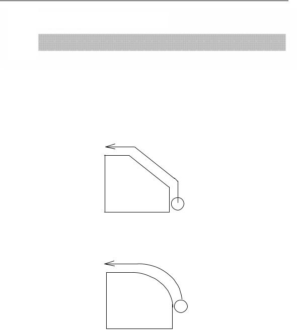
● Tool movement along a straight line
Workpiece |
Program
G01 X_ _ Y_ _ ; X_ _ ;
Tool
Fig.1.1 (a) Tool movement along a straight line
●Tool movement along an arc
Program
G03 X_ Y_ R_
Workpiece Tool
Fig. 1.1 (b) Tool movement along an arc
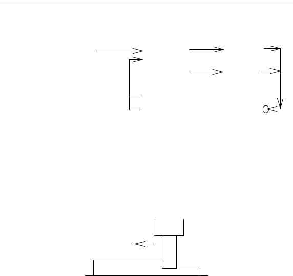
The tool moves along straight lines and arcs constituting the workpiece parts is called the interpolation function.
Symbols of the programmed commands G01, G02, ... are called the preparatory function and specify the type of interpolation conducted in the control unit.
PROGRAMMING-1 GENERAL 1-
|
Control unit |
|
||
(a) Movement along straight |
|
|
|
|
|
|
|
|
|
line |
|
interpolation |
|
X-axis(motor) |
G01 Y__; |
|
|
|
|
X__Y__; |
|
|
|
Y-axis(motor) |
|
|
|
|
|
(b) Movement along arc |
|
|
|
|
G03X__Y__R__; |
a)Movement along |
|
||
|
|
straight line |
|
|
|
b) Movement along |
|
||
|
|
arc |
Tool movement |
|
|
|
|
|
|
Fig. 1.1 (c) Interpolation function
NOTE:
Some machines move tables instead of tools but this manual assumes that tools are moved against workpieces.
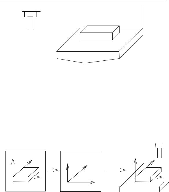
1.2 FEEDFEED FUNCTION(See II-5)
Movement of the tool at a specified speed for cutting a workpiece is called the feed.
F
mm/min Tool
Workpiece
Table
Fig. 1.2 (a) Feed function
Feedrates can be specified by using actual numerics. For example, to feed the tool at a rate of 150 mm/min, specify the following in program: F150.0
The function of deciding the feed rate is called the feed function (See II-5).
1.3 PART DRAWING AND TOOL MOVEMENT
1.3.1 Reference Position (Machine-specific position)
A CNC machine tool is provided with a fixed position. Normally, tool change and programming of absolute zero point as described later are performed at this position. This position is called the reference position.
PROGRAMMING-1 GENERAL 1-
Reference position
Tool
Workpiece
Table
Fig. 1.3.1 (a) Reference position
EXPLANATIONS
The tool can be moved to the reference position in two ways:
(1) Manual reference position return
Reference position return is performed by manual button operation.
(2) Automatic reference position return
In general, manual reference position return is performed first after the power is turned on. In order to move the tool to the reference position for tool change thereafter, the function of automatic reference position return is used.
1.3.2 Coordinate System on Part Drawing and Coordinate System Specified by CNC Coordinate System
|
|
|
|
Tool |
|
Z |
Y |
Y |
Z |
Y |
|
ProgramZ |
|
|
|||
|
|
|
|
||
|
X |
command |
|
workpiece |
X |
|
X |
|
|
||
|
|
|
|
|
|
|
Coordinate system |
|
|
|
|
|
Part drawing |
CNC |
Machine tool |
|
|
Fig. 1.3.2 (a) Coordinate system
PROGRAMMING-1 GENERAL 1-
EXPLANATIONS
●Coordinate system
The following two coordinate systems are specified at different locations:
(1) Coordinate system on part drawing
The coordinate system is written on the part drawing. As the program data, the coordinate values on this coordinate system are used.
(2) Coordinate system specified by the CNC
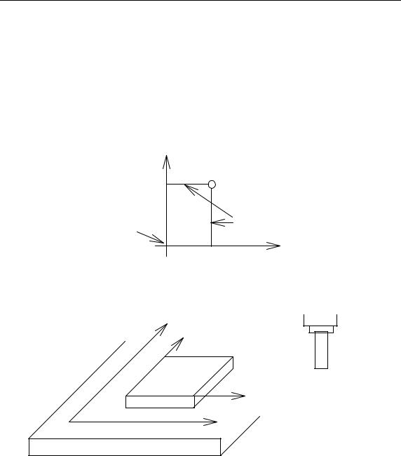
The coordinate system is prepared on the actual machine tool table. This can be achieved by programming the distance from the current position of the tool to the zero point of the coordinate system to be set.
200
|
|
Present tool position |
Program zero point |
300 |
Distance to the zero point of a |
|
0 |
coordinate system to be set |
|
|
Fig. 1.3.2 (b) Coordinate system specified by the CNC
The positional relation between these two coordinate systems is determined when a workpiece is set on the table.
Y
Y
Workpiece
X
Table
Tool
Coordinate system on part drawing established on the workpiece
X
Coordinate system specified by the CNC established on the table
Fig. 1.3.2 (c) Coordinate system specified by CNC and coordinate system on part drawing
The tool moves on the coordinate system specified by the CNC in accordance with the command program generated with respect to the coordinate system on the part drawing, and cuts a workpiece into a shape on the drawing. Therefore, in order to correctly cut the workpiece as specified on the drawing, the two coordinate systems must be set at the same position.
PROGRAMMING-1 GENERAL 1-
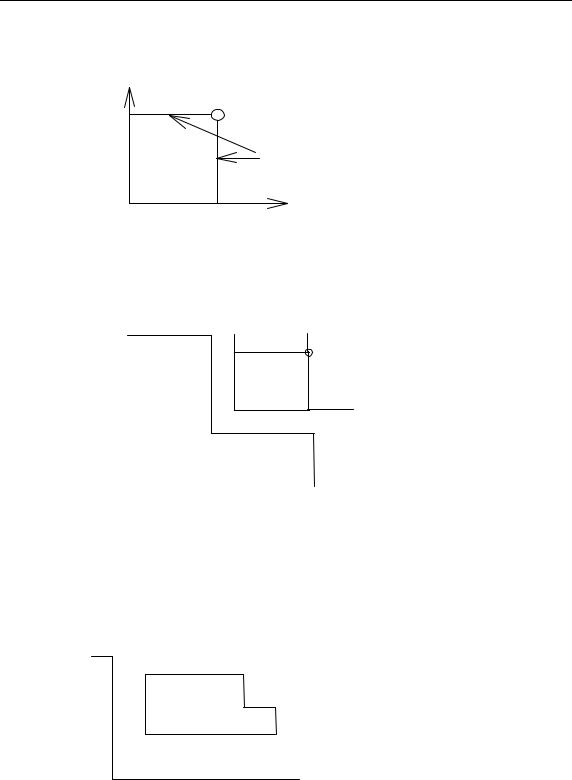
• Methods of setting the two coordinate systems in the same position
To set the two coordinate systems at the same position, simple methods shall be used according to workpiece shape, the number of machining.
(1) Using a standard plane and point of the workpiece.
Workpiece’s standard point
Fixed distance
Bring the tool center to the workpiece standard point. And set the coordinate system specified by CNC at this position.
(2) Mounting a workpiece directly against the jig
Program zero point
Jig
Meet the tool center to the reference position. And set the coordinate system specified by CNC at this position. (Jig shall be mounted on the predetermined point from the reference position.)
(3) Mounting a workpiece on a pallet, then mounting the workpiece and pallet on the jig
|
pallet |
|
Jig |
|
(Jig and coordinate system shall be |
|
Workpiece |
specified by the same as (2)). |
|
|
|
PROGRAMMING-1 GENERAL 1-
1.3.3 How to Indicate Command Dimensions for Moving the Tool – Absolute, Incremental instructions
EXPLANATIONS
Coordinate values of command for moving the tool can be indicated by absolute or incremental designation (See II-8).
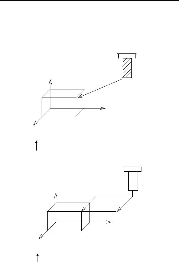
• Absolute coordinates
The tool moves to a point at ”the distance from zero point of the coordinate system” that is to the position of the coordinate values.
Tool
Z
A (15 60 40)
B (10 30 20)
Y
X
Command specifying movement from point A to point B
G90 X10.0 Y30.0 Z20.0;
Coordinates of point B
• Incremental coordinates
Specify the distance from the previous tool position to the next tool position.
Tool
Z
30 A 10
40
B
Y
X
Command specifying movement from point A to point B G91 X40.0 Y-30.0 Z-10.0;
Distance and direction for movement along each axis

PROGRAMMING-1 GENERAL 1-
1.4 CUTTING SPEED – SPINDLE SPEED FUNCTION(see II-9)
The speed of the tool with respect to the workpiece when the workpiece is cut is called the cutting speed. As for the CNC, the cutting speed can be specified by the
spindle speed in rpm unit.
Tool
Diameter
RPM
V (mm/min)
Workpiece
EXAMPLES
<When a workpiece should be machined with a tool 100 mm in diameter at a cutting speed of 80 mm/min. >
The spindle speed is approximately 250 rpm, which is obtained from N=1000v/πD. Hence the following command is required: S250;
Commands related to the spindle speed are called the spindle speed function (See II-9).
1.5 SELECTION OF TOOL USED FOR VARIOUS MACHINING (TOOL FUNCTION) (see II-10)
When drilling, tapping, boring, milling or the like, is performed, it is necessary to select a suitable tool. When a number is assigned to each tool and the number is specified in the program, the corresponding tool is selected.
Tool number
01
ATC magazine
02
PROGRAMMING-1 GENERAL 1-
EXAMPLES
<When No.01 is assigned to drilling tool>
When the tool is stored at location 01 in the ATC magazine, the tool can be selected by specifying T01. This is called the tool function (See II-10)
1.6 COMMAND FOR MACHINE OPERATIONS –MISCELLANEOUS FUNCTION
When machining is actually started, it is necessary to rotate the spindle, and feed coolant. For this purpose, on-off operations of spindle motor and coolant valve should be controlled (See II-11).
Spindle rotate
Tool coolant
Workpiece |
The function of specifying the on-off operations of the components of the machine is called the miscellaneous function. In general, the function is specified by an M code. For example, when M03 is specified, the spindle is rotated clockwise at the specified spindle speed.
1.7 PROGRAM CONFIGURATION
A group of commands given to the CNC for operating the machine is called the program. By specifying the commands, the tool is moved along a straight line or an arc, or the spindle motor is turned on and off. In the program, specify the commands in the sequence of actual tool movements.
Block |
Block
|
|
|
|
|
|
Tool |
movement |
|
|
|
Block |
|
|||
|
|
|
|
|
sequence |
|
|
Program |
|
|
|
|
|
|
|
|
|
Block |
|
|
|||
|
|
|
|
|
|
||
|
|
|
|
|
|
|
|
|
|
|
|
|
|
|
|
Block
Fig. 1.7 (a) Program configuration
PROGRAMMING-1 GENERAL 1-
A group of commands at each step of the sequence is called the block. The program consists of a group of blocks for a series of machining. The number for discriminating each block is called the sequence number, and the number for discriminating each program is called the program number (See II-12).
EXPLANATIONS
• Block
The block and the program have the following configurations. 1 Block
NOOOO GOO XOO.O YOO.O MOO SOO TOO;
N:Sequence number
G: Preparatory function
X, Y: Dimension word
M:Miscellaneous function
S:Spindle function
T:Tool function
; : End of block Fig. 1.7 (b) Block configuration
A block has a sequence number at its head, which identifies the block, and an end-of-block code at the end, indicating the end of the block. This manual indicates the end-of-block code by ;.
• Program
Normally, a program number is specified after the end-of-block (;) code at the beginning of the program, and a program end code (M02 or M30) is specified at the end of the program.
O□□□□ Program number Block
Block
Block
M30 |
End of program |
Fig. 1.7 (c) Program configuration
• Main program and subprogram
When machining of the same pattern appears at many portions of a program, a program for the pattern is created. This is called the subprogram. On the other hand, the original program is called the main program. When a subprogram execution command appears during execution of the main program, commands of the subprogram are executed. When execution of the subprogram is finished, the sequence returns to the main program.
PROGRAMMING-1 GENERAL 1-
Main program |
subprogram#1 |
|
|
|
|
O1001 |
program for |
|
M98P1001 |
||
|
|
||
|
|
pole #1 |
|
|
|
M99 |
|
|
M98P1002 |
|
|
|
subprogram#2 |
|
|
|
|
|
|
|
M98P1001 |
O1002 |
program for |
|
|
||
|
|
|
pole#2 |
|
|
M99 |
|
|
|
|
|
Pole #1 Pole #1
Pole #2Pole #2
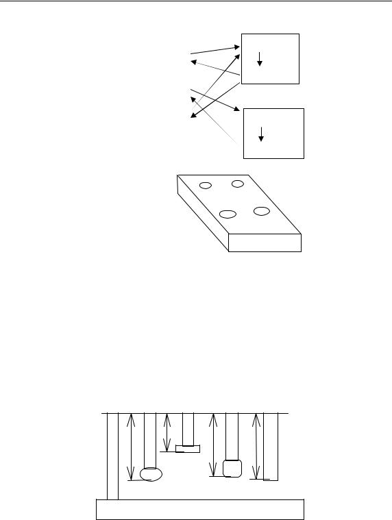
1.8 TOOL FIGURE AND TOOL MOTION BY PROGRAM
EXPLANATIONS
•Machining using the end of cutter-Tool length compensation function (See II-14.1) Usually, several tools are used for machining one workpiece. The tools have different tool length. It is very troublesome to change the program in accordance with the tools. Therefore, the length of each tool used should be measured in advance. By setting the difference between the length of the standard tool and the length of each tool in the CNC (data display and setting: see III-11), machining can be performed without altering the program even when the tool is changed. This function is called tool length compensation.
H2 |
H3 |
H1 |
H4 |
|
|
|
Workpiece |
PROGRAMMING-1 GENERAL 1-
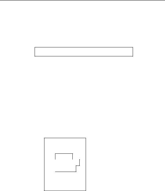
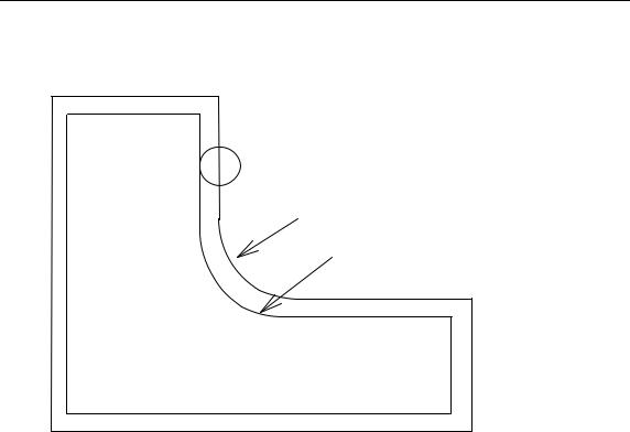
• Machining using the Side of cutter-Cutter compensation function (See II-14.2) Because a cutter has a radius, the center of the cutter path goes around the workpiece with the cutter radius deviated.
Tool
Cutter path using cutter compensation
Machined part figure
Workpiece
If radius of cutters are stored in the CNC (Data Display and Setting: see III-11), the tool can be moved by cutter radius apart from the machining part figure. This function is called cutter compensation.
PROGRAMMING-1 GENERAL 1-
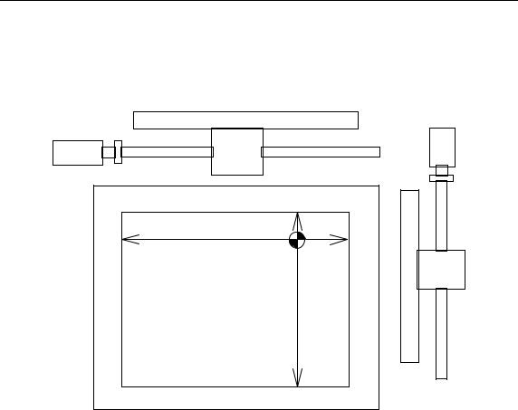
1.9 TOOL MOVEMENT RANGE-STROKE
Limit switches are installed at the ends of each axis on the machine to prevent tools from moving beyond the ends. The range in which tools can move is called the stroke.
Table
motor
Reference position |
Besides strokes defined with limit switches, the operator can define an area which the tool cannot enter using a program or data in memory (see III-11). This function is called stroke check.

PROGRAMMING-2 (CONTROLLED AXES) 2 - 0
2CONTROLLED AXES
2.1 CONTROLLED AXES
Number of controlled axes |
K1000M:3 axes X,Y,Z |
K1000M4:4 axes |
|
X,Y,Z,4th |
|||
|
|
||
Simultaneously controlled axes |
K1000M:3 axes |
K1000M4:4 axes |
|
|
|
|
2.2 NAME OF AXES
Names of the three basic axes are fixed as X, Y, and Z. Names of additional axes can be optionally selected from A, B, C, U, V, and W. They can be set by parameter No. 008 #2, #3, #4.
2.3 INCREMENT SYSTEM
Least command increment |
Least input increment |
Maximum stroke |
|
|
|
0.001mm |
0.001mm |
9999.99mm |
|
|
|
0.0001inch |
0.0001inch |
999.9999inch |
|
|
|
Combined use of the inch system and the metric system is not allowed. There are functions that cannot be used between axes with different unit systems (circular interpolation, cutter compensation, etc.). For the increment system, see the machine tool builder’s manual.
2.4 MAXIMUM STROKE
Maximum stroke = Least command increment x 99999999
See 2.3 Increment System.
PROGRAMMING-3 PREPARATORY FUNCTION 3 -
3PREPARATORY FUNCTION G FUNCTION
3 PREPARATORY FUNCTION G CODES
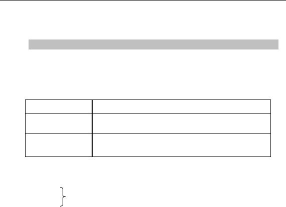
A number following address G determines the meaning of the command for the concerned block. G codes are divided into the following two types.
Type
One-shot G code
Modal G code
Meaning
The G code is effective only in the block in which it is specified.
The G code is effective until another G code of the same group is specified.
Example:
G01 and G00 are modal G codes in group 01.
G01X _;
Z _; |
G01 is effective in this range. |
X _; |
|
G00 Z_; |
|
Explanations
1.Modal G codes have the following initial conditions when the power is turned on or the system is reset to the clear state (bit 6 of parameter No. 045).
1)Those G codes marked* in Table 3 are specified automatically.
2)G20 and G21 retain their original conditions.
3)G00 or G01 is automatically selected according to parameter setting.
2.The G codes of group 00 are one-shot G codes.
3.If a G code that does not appear in the G code list is specified, or a G code whose options are not supported is specified, alarm No. 010 is displayed.
4.Multiple G codes of different groups can be specified in a single block. When multiple G codes of one group are specified in a block, the G code specified last is effective.
5.If any G code of group 01 is specified in a canned cycle mode, the canned cycle is automatically cancelled and the G80 condition is entered. However, a G code of group 01 is not affected by any of the canned cycle G codes.
6.A G code is displayed from each group.

PROGRAMMING-3 PREPARATORY FUNCTION 3 -
Table 3 G code list (1/2)
G code |
Group |
Function |
|
|
|
|
|
G00 |
|
Positioning |
|
*G01 |
01 |
Linear interpolation |
|
G02 |
Circular interpolation CW |
||
|
|||
G03 |
|
Circular interpolation CCW |
|
G04 |
00 |
Dwell, Exact stop |
|
G10 |
Offset value setting |
||
|
|||
*G17 |
|
XY plane selection |
|
G18 |
02 |
ZX plane selection |
|
G19 |
|
YZ plane selection |
|
G20 |
06 |
Input in inch |
|
G21 |
Input in mm |
||
|
|||
|
|
|
|
G27 |
|
Reference position return check |
|
G28 |
|
Return to reference position |
|
|
00 |
|
|
G29 |
Return from reference position |
||
G31 |
|
Skip function |
|
G39 |
|
Corner circular interpolation |
|
*G40 |
|
Cutter compensation cancel |
|
G41 |
07 |
Cutter compensation left |
|
G42 |
|
Cutter compensation right |
|
G43 |
|
Tool length compensation + direction |
|
G44 |
08 |
Tool length compensation - direction |
|
*G49 |
|
Tool length compensation cancel |
|
*G54 |
|
Workpiece coordinate system 1 selection |
|
G55 |
|
Workpiece coordinate system 2 selection |
|
G56 |
05 |
Workpiece coordinate system 3 selection |
|
G57 |
Workpiece coordinate system 4 selection |
||
|
|||
G58 |
|
Workpiece coordinate system 5 selection |
|
|
|
|
|
G59 |
|
Workpiece coordinate system 6 selection |
|
G65 |
00 |
Macro call |
|
|
|
|

PROGRAMMING-3 PREPARATORY FUNCTION 3 -
Table 3 G code list(2/2)
G code |
Group |
Function |
|
|
|
|
|
G73 |
|
Peck drilling cycle |
|
G74 |
|
Counter tapping cycle |
|
G76 |
|
Fine boring cycle |
|
|
|
|
|
*G80 |
|
Canned cycle cancel |
|
|
|
|
|
G81 |
|
Drilling cycle, spot boring cycle or external operation function |
|
|
|
|
|
G82 |
09 |
Drilling cycle or counter boring cycle |
|
G83 |
Peck drilling cycle |
||
|
|||
G84 |
|
Tapping cycle |
|
G85 |
|
Boring cycle |
|
G86 |
|
Boring cycle |
|
G87 |
|
Back boring cycle |
|
G88 |
|
Boring cycle |
|
|
|
|
|
G89 |
|
Boring cycle |
|
|
|
|
|
G93 |
01 |
Tapping cycle |
|
G90 |
03 |
Absolute command |
|
G91 |
Increment command |
||
|
|||
G92 |
00 |
Setting for work coordinate system |
|
G98 |
10 |
Return to initial point in canned cycle |
|
G99 |
Return to R point in canned cycle |
||
|
PROGRAMMING-4(INTERPOLATION FUNCTIONS) |
4 - 0 |
4INTERPOLATION FUNCTIONS
4.1 POSITIONING (G00)
The G00 command moves a tool to the position in the workpiece system specified with an absolute or an incremental command at a rapid traverse rate. In the absolute command, coordinate value of the end point is programmed. In the incremental command the distance the tool moves is programmed.
Format
G00 IP _;
IP _: For an absolute command, the coordinates of an end position, and for an incremental command, the distance of the tool moves.
Explanations
Tool path generally does not become a straight line. Start position
on linear position
End position
NOTE:
1 The rapid traverse rate in the G00 command is set by the parameter No. 038 to 040 for each axis independently by the machine tool builder. The rapid traverse rate cannot be specified in the address F. Feed rate specified by address F is valid.
2The above parameter is in 3-axis NC system. When 4-axis is selected, parameter number is in APPENDIX 7 note2 and 3. Parameter number without special description in this manual is in 3-axis CNC system.
4.2 LINEAR INTERPOLATION (G01)
Format
G01 IP _F_;
IP _: For an absolute command, the coordinates of an end position, and for an incremental command, the distance of the tool moves.
F_; Speed of tool feed (Feedrate)
Explanations
A tools move along a line to the specified position at the feedrate specified in F. The feedrate specified in F is effective until a new value is specified. It need not be specified for each block. It is set by the parameter of No.65. The feedrate commanded
Loading...