


 Loading...
 CNC Series
KND—1000 T /1000 T CNC system for Lathe
USER’S MANUAL
Beijing KND CNC Technique Co. Ltd.
B12B-T00N-0101
C KND LTD,2006
CONTENTS
I GENERAL…………………………………………………………………………………… 1 - 0
1.GENERAL …………………………………………………………………………………… 1 - 1
1.1GENERAL FLOW OF OPERATION OF CNC MACHINE TOOL …………………… 1 - 1
1.2NOTES ON READING THIS MANUAL………………………………………………… 1 - 2
II PROGRAMMING ……………………………………………………………………… 1 - 0
1.GENERAL …………………………………………………………………………………… 1 - 1
1.1TOOL MOVEMENT ALONG WORKPIECE PARTS FIGURE-INTERPOLATION… 1 - 2
1.2FEED-FEED FUNCTION………………………………………………………………… 1 - 4
1.3PART DRAWING AND TOOL MOVEMENT ………………………………………… 1 - 3
1.4CUTTING FEED─SPINDLE SPEED FUNCTION …………………………………… 1 - 9
1.5SELECTION OF TOOL USED FOR VARIOUS MACHINING-TOOL FUNCTION… 1 - 10
1.6COMMAND FOR MACHINE OPERATIONS MISCELLANEOUS FUNCTION …… 1 - 10
1.7PROGRAM CONFIGURATION ………………………………………………………… 1 - 11
1.8TOOL COMPENSATION FUNCTION ………………………………………………… 1 - 13
1.9TOOL MOVEMENT RANGE –STROKE ……………………………………………… 1 - 13
2.CONTROLLED AXES …………………………………………………………………… 2 - 1
2.1CONTROLLED AXES …………………………………………………………………… 2 - 1
2.2SETTING UNIT …………………………………………………………………………… 2 - 1
2.3MAXIMUM STROKES …………………………………………………………………… 2 - 1
3.PREPARATORY FUNCTION (G FUNCTION) ……………………………………… 3 - 1
4.INTERPOLATION FUNCTIONS………………………………………………………… 4 - 1
4.1POSITIONING (G00) …………………………………………………………………… 4 - 1
4.2LINEAR INTERPOLATION (G01) ……………………………………………………… 4 - 2
4.3CIRCULAR INTERPOLATION (G02,G03) …………………………………………… 4 - 2
5.THREAD CUTTING ……………………………………………………………………… 5 - 1
5.1THREAD CUTTING(G32) ……………………………………………………………… 5 - 1
5.2 unequal lead thread cuttingG34 …………………………………………………… |
5 |
- 6 |
6. FEED FUNCTION ……………………………………………………………………… |
6 |
- 1 |
6.1 RAPID TRAVERS ……………………………………………………………………… |
6 |
– 1 |
6.2 CUTTING FEEDRATE ………………………………………………………………… |
6 |
- 1 |
6.3 AUTOMATIC ACCELERATION/DECELERATION ………………………………… |
6 |
- 3 |
6.4 SPEED CONTROL AT COMERS OF BLOCKS …………………………………… |
||
6.5 DWELL(G04) …………………………………………………………………………… |
6 |
- 4 |
|
6 |
- 5 |
7.REFERENCE POSITON ………………………………………………………………… 7 - 1
7.1AUTOMATIC REFERENCE POINT TETURN(G28) ………………………………… 7 - 1
8.COORDINATE SYSTEM SETTING(G50)…………………………………………… 8 - 1
8.1 COORDINATE SYSTEM SETTING…………………………………………………… |
8 |
- 1 |
8.2 COORDINATE SYSTEM SHIET ……………………………………………………… |
8 |
- 1 |
8.3 AUTOMATIC COORDINATE SYSTEM SETTING…………………………………… 8 - 2 |
||
8.4 WORK COORDINATE SYSTEM SHIFT……………………………………………… |
8 |
- 3 |
8.5 DIRECT MEASURED VALUE INPUT FOR WORK COORDINATE SYSTEM |
|
|
SHIFT ……………………………………………………………………………………… 8 - 4 |
||
9.COORDINATE VALUE AND DIMENSION …………………………………………… 9 |
- 1 |
|
9.1ABSOLUTE AND INCTEMENTAL PROGRAMMING………………………………… 9 - 1
9.2INCH/METRIC CONVERSION(G20,G21) …………………………………………… 9 - 3
9.3DECIMAL POINT PROGRAMMING/POCKET CALCULATOR TYPE DECIMAL
POINT PROGRAMMING ………………………………………………………………… 9 - 3
9.4DIAMETER AND RADIUS PROGRAMMING ………………………………………… 9 - 5
10.SPINDLE FUCTION(S FUCTION) …………………………………………………… 10- 1
10.1SPINDLE SPEED COMMAND ……………………………………………………… 10- 1
10.2SIMULATING SPINDLE GEAR SHIFTING ………………………………………… 10- 2
10.3CONSTANT SUREACE SPEED CONTROL(G96,G97) …………………………… 10- 4
10.4CONTROLLING SPINDLE CHUCK…………………………………………………… 10- 8
10.5CONTROLLING TALSTOCK ………………………………………………………… 10- 8
10.6SPINDLE ROTATION DWELL FUNCTION ………………………………………… 10- 9
11.TOOL FUNCTION (T FUNCTION) …………………………………………………… 11- 1
11.1TOOL-CHANGING PROCEDURE …………………………………………………… 11- 1
11.2FUNCTION FOR CHECKING INPUT SIGNAL OF TOOL CARRIER …………… 11- 2
11.3SELECTING REAR TOOL CARRIER………………………………………………… 11- 3
11.4PARAMETERS RELATIVE WITH TOOL CHANGING……………………………… 11- 3
12.MISCELLANEOUS FUNCTION ……………………………………………………… 12- 1
12.1MISCELLANEOUS FUNCTION(M FUNCTION……………………………………… 12- 1
12.2 USER INTERFACE GO TO FUNCTIONM CODE:M91/M92,M93/M94 ………… 12- 3
12.3SPECIAL M CODE:M21/M22,M23/M24 ……………………………………………… 12- 4
12.4PARAMETERS OF MISCELLANE:M21/M22,M23/M24 …………………………… 12- 4
13.PROGRAM CONFIGURATION ……………………………………………………… 13- 1
13.1PROGRAMR …………………………………………………………………………… 13- 1
13.2PROGRAM END………………………………………………………………………… 13- 7
13.3TABE END ……………………………………………………………………………… 13- 8
14.FUNCTIONS TO SIMPLIFY PROGRAMMING …………………………………… 14- 1
14.1CANNED CYCLE (G90,G92,G94.G93) ……………………………………………… 14- 1
14.2MULTIPLE REPETITIVE CYCLE(G70~G76)………………………………………… 14-09
14.3CHAMFERING AND CORNER ……………………………………………………… 14-21
15.COMPENSATION FUNCTION………………………………………………………… 15- 1
15.1TOOLOFFSET ………………………………………………………………………… 15- 1
15.2TOOL NOSE RADIUS COMPENSATION(G40 TO G42)…………………………… 15- 4
15.3CHANGING OF TOOL OFFSET AMOUNT(PROGRAMMABLE DATE
INPUT)(G10)…………………………………………………………………………………… 15-40
16.MANUAL MEASURE INPUT OF TOOL COMPENSATION …………………… 16- 1
16.1OFFSET INPUT BY COUNTING……………………………………………………… 16- 1
16.2MEASURE INPUT……………………………………………………………………… 16- 1
16.3THE 2 WAYOF OFFSET INPUT …………………………………………………… 16- 2
17.MEASURE FUNCTION ………………………………………………………………… 17- 1
17.1SKIP FUNCTION (G31)………………………………………………………………… 17- 1
17.2ZUTOMATIC TOOL OFFSET(G36,G37) …………………………………………… 17- 2
18.WORKPIECE COORDINATE SYSTEM (G54~G59) …………………………… 18- 1
18.1WORKPIECE COORDINATE SYSTEM……………………………………………… 18- 1
18.2SHIFT OR CHANGE WORKPIECE COORDINATE SYSTEM(G10) …………… 18- 2
18.3AUTOMATIC COOTDINATE SYSTEM SETTING ………………………………… 18- 3
19.CUSTOM MACRO COMMAND ……………………………………………………… 19- 1
19.1CUSTOM MACRO COMMAND ……………………………………………………… 19- 1
19.2CUSTOME MACRO BODY …………………………………………………………… 19- 1
13.3APPLICATION OF CUSTOM MACTOM MACRO…………………………………… 19-10
III OPERATION……………………………………………………………………………… 1 - 0
1.GENERAL……………………………………………………………………………………… 1 - 1
1.1MANUAL OPERATION ………………………………………………………………… 1 - 1
1.2TOOL MOVEMENT BY PROGRAMING-AUTOMATIC OPERATION……………… 1 - 2
1.3AUTOMATIC OPERATION……………………………………………………………… 1 - 3
1.4TESTING A PROGRAM ………………………………………………………………… 1 - 4
1.5EDITING A PART PROGRAM ………………………………………………………… 1 - 7
1.6DISPLAYING AND SETTING DATA ………………………………………………… 1 - 8
1.7DISPLAY ………………………………………………………………………………… 1 -11
1.8DATA INPUT/OUTPUT ………………………………………………………………… 1 - 13
2.OPERATIONAL DEVICES ……………………………………………………………… 2 - 1
2.1LCD MDI PANEL ……………………………………………………………………… 2 - 1
2.2MACHINE TOOL OPERATIR’S PABEL ……………………………………………… 2 - 6
3.POWER ON / OFF…………………………………………………………………………… 3 - 1
3.1TUMING ON THE POWER……………………………………………………………… 3 - 1
3.2TURING OFF THE POWER …………………………………………………………… 3 - 1
4.MANUAL OPERATION …………………………………………………………………… 4 - 1
4.1MANUAL REFERENCE POSITION RETURN………………………………………… 4 - 1
4.2JOG FEE ………………………………………………………………………………… 4 - 2
4.3STEP FEED ……………………………………………………………………………… 4 - 4
4.4MANUAL HANDLE FEED (OPTIONAL FUNCTION) ………………………………… 4 - 5
4.5MANUAL PROGRAM ZERO RETURN ZERO MODF ……………………………… 4 - 6
4.6MANUAL ABSOLUTE ON/OFF ………………………………………………………… 4 - 6
4.7MANUAL AUXILIARY FUNCTION OPERATION …………………………………… 4 - 10
5.AUTOMATIC OPERATION ……………………………………………………………… 5 - 1
5.1OPERATION MODE……………………………………………………………………… 5 - 1
5.2AUTOMATIC OPERATION EXECUTION……………………………………………… 5 - 3
5.3AUTO OPERATION EXECUTION……………………………………………………… 5 - 3
5.4STOPING AND TERMINATING AUROMATIC OPERATION ……………………… 5 - 3
6.DRY RUN……………………………………………………………………………………… 6 - 1
6.1ALL-AXIS MACHINE LOCK …………………………………………………………… 6 - 1
6.2AUXILIARY FUCTION LOCK …………………………………………………………… 6 - 1
6.3FEEDRATE OVERRIDE ………………………………………………………………… 6 - 1
6.4RAPID TRAVERSE OVERRIDE ……………………………………………………… 6 - 2
6.5DRY RUN ………………………………………………………………………………… 6 - 3
6.6SINGLE BLOCK ………………………………………………………………………… 6 - 3
6.7RESTART ………………………………………………………………………………… 6 - 5
6.8OPTIONAL BLOCK SKIP ……………………………………………………………… 6 - 5
7.SAFTY OPERATION ……………………………………………………………………… 7 - 1
7.1EMERGENCY STOP …………………………………………………………………… 7 - 1
7.2OVERTRAVEL …………………………………………………………………………… 7 - 1
8.ALARM FUNCTION ……………………………………………………………………… 8 - 1
9.PROGRAM STORAGE AND EDITING ……………………………………………… 9 - 1
9.1PREPARATION…………………………………………………………………………… 9 - 1
9.2PROGRAM STORAGETO MEMORY ………………………………………………… 9 - 1
9.3 FILE INCLUDING MANY PROGRAMS STORED INTO MEMORY ……………… 9 - 2
9.4PROGRAM SEARCH …………………………………………………………………… 9 - 2
9.5DELETING PROGRAM ………………………………………………………………… 9 - 3
9.6ALL PROGRAMS DELETING…………………………………………………………… 9 - 3
9.7PROGRAM OUTPUT …………………………………………………………………… 9 - 3
9.8ALL PROGRAMS OUTPUT …………………………………………………………… 9 - 4
9.9SEQUENCE NUMBER SEARCH ……………………………………………………… 9 - 4
9.10PROGRAM COMPARATION BETWEEN IN MEMORY AND IN
PROGRAMMER ………………………………………………………………………… 9 - 5 9.11 INSERTING, ALTERING AND DELETING A WORD ……………………………… 9 - 5
9.12SEQUENCE NUMBER TO BE INSERTED AUTOMATICALLY…………………… 9 - 10
9.13NUMBER OF REGISTERED PROGRAMS ………………………………………… 9 - 11
9.14STORAGE CAPACITY ………………………………………………………………… 9 - 11
10.DATA DISPLAY AND SET …………………………………………………………… 10- 1
10.1OFFSET ………………………………………………………………………………… 10 - 1
10.2SETTING THE SET PARAMETER …………………………………………………… 10 - 3
10.3CUSTOM MACRO VARIABLES DISPLAY AND SETTING ……………………… 10 - 5
10.4PARAMETER …………………………………………………………………………… 10 - 6
10.5PITCH ERROR COMPENSATION DATA …………………………………………… 10 - 9
10.6DIAGNOSE AND PLC PARAMET …………………………………………………… 10 - 9
10.7DISPLAY AND SET MACHINE SOFTWARE OPERATOR’S PANEL …………… 10 -10
11.DISPLAY …………………………………………………………………………………… 11- 1
11.1STATUS INDICATION ………………………………………………………………… 11 - 1
11.2DATA KEYED IN DISPLAYING ……………………………………………………… 11 - 1
11.3SEQUENCE NUMBER AND PROGRAM NUMBER DISPLAY …………………… 11 - 1
11.4PROGRAM MEMORY USAGE DISPLAY …………………………………………… 11 - 2
11.5COMMAND VALUE DISPLAY ………………………………………………………… 11 - 2
11.6CURRENT POSITION DISPLAY……………………………………………………… 11 - 4
11.7RUNTIME AND PARTS COUNT DISPLAY ………………………………………… 11 - 6
11.8ALARM DISPLAY ……………………………………………………………………… 11 - 7
11.9INDEX DISPLAY ……………………………………………………………………… 11 - 7
12.DATA OUTPUT AND FLASH MEMORY…………………………………………… 12 - 1
12.1TOOL COMPENSATION ……………………………………………………………… 12 - 1
12.2PARAMETER …………………………………………………………………………… 12 - 1
12.3FLASH MEMORY ……………………………………………………………………… 12 - 1
13.GRAPH FUNCTION ……………………………………………………………………… 13 - 1
13.1SET GRAPH PARAMETER …………………………………………………………… 13 - 2
13.2DESCRIPTIONPARAMETER ………………………………………………………… 13 - 3
13.3DESCRIPTION OF TOOL PATH……………………………………………………… 13 - 4
13.4EXAMPLE ……………………………………………………………………………… 13 - 5
14.UPPER LIMIT FEED……………………………………………………………………… 14 - 1
14.1UPPER LIMIT FEED …………………………………………………………………… 14 - 1
14.2SETTING RAPID TRAVERSE ………………………………………………………… 14 - 1
14.3SETTING ELECTRIC GEAR RATE N ……………………………………………… 14 - 1
14.4SETTING ACCELERATION/DECELERATION TIME CONCTANT ……………… 14 - 2
14.5PARAMETER SETTING ……………………………………………………………… 14 - 2
14.6DRIVER ALARM………………………………………………………………………… 14 - 5
15.DESCRIPTION …………………………………………………………………………… 15 - 1
15.1STANDARD PARAMETER SETTING AND MEMORY CLEARING ……………… 15 - 1
15.2NOT CHECK SOFT OVER TRAVEL ………………………………………………… 15 - 1
15.3BACKLASH COMPENSATION DESTIPTION ……………………………………… 15 - 1
15.4KEYBOARD AND INPUT SIGNAL FILTER ………………………………………… 15 - 1
15.5TURN ON THE POWER NOT TO ENTER NORMAL SCREEN ………………… 15 - 2
15.6ROM PARITY ALARM,CMOSDATA LOSE, RAM CHECK ………………………… 15 - 2
16. ILLUSTRATION OF USING U DISK ( TYEP SYSTEM) …………………… |
16 - 1 |
16.1 U DISK AND FILE SYSTEM………………………………………………………… |
16-1 |
16.2SYSTEMFUNCTION ……………………………………………………………… 16-1
IV CONNECTION ………………………………………………………………………… 1 - 0
1.SYSTEM STRUCTURE…………………………………………………………………… 1 - 1
1.1SYSTEM CONFIGURATION…………………………………………………………… 1 - 1
1.2INSTALLATION DIMENSION OF CNC CONTROL UNIT…………………………… 1 - 3
1.3ADDITIONAL OPERATOR’S PANEL DIMENSION ………………………………… 1 - 4
2.INTERNAL CONNECTION……………………………………………………………… 2 - 1
2.1SYSTEM INTERNALCONNECTION DIAGRAM……………………………………… 2 - 1
2.2POWER SOCKET SIGNAL ARRANGEMENT………………………………………… 2 - 3
2.3CNC MAINBOARD SWITCH DESCRIPTION ………………………………………… 2 - 3
3.EXTERNAL CONNECTION …………………………………………………………… 3 - 1
3.1SYSTEM EXTERNAL CONNECTION DIAGRAM …………………………………… 3 - 1
3.2INTERFACE SIGNAL FROM CNC TO DRIVER……………………………………… 3 - 3
3.3RS232-C STANDARD SERIES PORT………………………………………………… 3 - 10
3.4ANALOGUE SPINDLE INTERFACE CONNECTION………………………………… 3 - 10
3.5CONNECTION OF ADDITIONAL OPERATOR’S PANEL ………………………… 3 - 11
3.6OPTIONAL OPERATOR’S PANEL …………………………………………………… 3 - 13
3.7 |
Spindle coder CONNECTION ………………………………………………………… |
3 |
- 13 |
3.8 |
Connection of the Can bus interface ………………………………………………… |
3 |
- 15 |
4. MACHINE TOOL INTERFACE ……………………………………………………… |
4 |
- 1 |
|
4.1DESCRIPTION OF INPUT SIGNAL INTERFACE …………………………………… 4 - 1
4.2DESCRIPTION OF OUTPUT SIGNAL INTERFACE ………………………………… 4 - 3
4.3THE TABLE OF INPUT AND OUTPUT SIGNAL …………………………………… 4 - 5
4.4DESCRIPTION OF INPUT AND OUTPUT SIGNAL ………………………………… 4 -10
V APPENDIXES …………………………………………………………………………… 1 |
– 0 |
|
APPENDIX 1 STORED PITCH ERROR COMPENSATON FUNCTION …………………… 1 |
- 1 |
|
APPENDIX2 |
G FUNCTION TABLE …………………………………………………………… 2 |
- 1 |
APPENDIX3 |
TABLE OF RANGE OF COMMAND VALUE ………………………………… 3 |
- 1 |
APPENDIX4 |
BINARY AND DECIMAL CONVERSION ……………………………………… 4 |
- 1 |
APPENDIX5 |
ALARM LIST ……………………………………………………………………… 5 |
- 1 |
APPENDIX6 |
STATUS OF POWER ON, AT RESET ………………………………………… 6 |
- 1 |
APPENDIX7 |
SPECIFION TABLE ……………………………………………………………… 7 |
- 1 |
APPENDIX8 PLC PARAMETER AND DIAGNOSE MESSAGE …………………………… 8 |
- 1 |
|
1. DIAGNOSE DATA ……………………………………………………………………… |
8 |
- 5 |
2. PLC PARAMETER ………………………………………………………………………… |
8 |
- 5 |
APPENDIX9 PARAMETERS …………………………………………………………………… 9 |
- 1 |
|
APPENDIX10 OPERATION LIST ……………………………………………………………… 10- 1 |
||
APPENDIX11 CNC STATUS DIAGNOSE MESSAGE………………………………………… |
11- 1 |
|
APPENDIX12 MACHINE DEBUG ……………………………………………………………… 12- 1
12.1TOOL SETTING ………………………………………………………………………… 12- 1
12.2FUNCTION FOR STARTING AT ANY POINT ……………………………………… 12- 7
12.3AKKITIONAL OPERATOT PANEL FOR MACHINE………………………………… 12-11
12.4FUNCTION OF SPINDLE PAUSE …………………………………………………… 12-11
12.5FUNCTION FOR CHECKING INPUT SIGNAL OF TOOL HOLDER……………… 12-11 APPENDIX13 INSTRUCTIONS OM KND COMMUNICATION SOFTWARE ……………… 13- 1

Overview 1(General) 1 0
I.OVERVIEW

Overview 1(General) 1 1
SECTION I.OVERVIWE
1. GENERAL
 K1000T achieves hi-speed and hi-accuracy control by using a 32-bit processor.
 The screen is a monochrome 7.5″ LCD with resolution 640×480.
 The main board is a 6-layer circuit board, with surface-mounted elements, and customized FPGA, so that it is highly integrated, the whole unit has a reasonable process structure, high interference immunity and reliability.
 Full-Chinese operation interface, complete Help info, easy to operate.
 Using G commands from international standard, compatible with FANUC system.
 Completely new molded panel in internationally popular color, with elegant appearance.
 Super-strong program command processing capability, up to 10000 pieces/18sec, can achieve hi-speed mini-line cutting.
 With function for lead screw error compensation.
 Hi-speed thread machining, rapid retreat.
 Employing electronic disk, data will be saved in several positions, can restore rapidly at an error.
 Program memory with high capacity (640k byte).
 DI/DO can be expanded freely by CAN bus. (Under development)
 Type system has a interface for disk U, through which realizes saving procedures between system and U disk mutually.
 Type system panel does not contain the keys of machine tool, the user can assemble by oneself or match the standard machine tool operator's panel.
This manual introduces the programming, operation and connection of KND 1000T CNC system for drilling, boring, milling machines and machining centers.
This manual describes all optional functions of KND 1000T, in “specification list” under appendices it has also introduced varied functions of the CNC system. Look up the options incorporated into your system in the manual written by the machine tool builder. Also look up the manual written by the machine tool builder for the specification, operation for the operator’s panel.
K1000T system has following variety:
●K1000TA : type structure , panel dimension:400×306 , Using 7.4″ monochrome LCD.
●K1000TB : type structure , panel dimension:400×306 , Using 7.5″ color LCD.
Overview 1(General) 1 2
●K1000TA : type structure , panel dimension:400×200 ,Using 7.4″ monochrome LCD.
●K1000TD : type structure , panel dimension:400×200 ,Using 8.4″ TFT color LCD.
May select and match Machine tool Operator’s panel regarding K1000T system, this panel apart two parts. the left part install the manual handle, the range selector, emergency stop switch, the three-position switch, the circulation starting switch, the power switch and so on; the right part is the machine tool keys, including 50 keys and 50 indicating lamps, when under the open style PLC system software, the key and the lamp function may from the definition.
The difference between type and type structure is as follow :
1.Panel dimension is different. type : 400×306 , type :400×200
2.type without machine tool keys, may match independence machine tool operator’s panel .
3.type system panel has USB and RS232 interfaces.
The supplementary material of KND-1000T is as follows:
KND1000T USER’S MANUAL
Contain system programming, operation, connection and routine maintenance.
1.1 GENRAL FLOW OF OPERATION OF OPERATION OF CNC
MACHINE TOOL
When machining a part using the CNC machine tool, first prepares the program, and then operates the CNC machine by using the program.
(1)First, prepare the program from a part drawing for cutting. How to prepare the program is described in “II. PROGRAMMING”.
(2)The program is to be read into the CNC system. Then, mount the workpieces and tools on the machine, and operate the tools according to the programming. Finally, execute the machining actually.
How to operate the CNC system is described in “III. OPERATION”.
Part |
Cutting |
MDI/LCD |
|
||
drawing |
program |
Machine |
|
|
|
|
|
CNC |
|
|
system |
|
|
Disk |
Refer to‘Programming’ |
Refer to‘Operation’ |
|
|
|
|
1.2 NOTES ON READING THIS MANUAL
The function of a CNC machine tool system depends not only on the CNC, but on the combination of the machine tool, its magnetic cabinet, and driving system, etc. And details about the function, programming, and operation relating to all combinations can

Overview 1(General) 1 3
be determined only based on a concrete machine.
Option |
|
Option |
|
|
|
|
|||
function 1 |
. . . |
function N |
|
|
|
|
|
Interface |
|
CNC basic function |
||||
|
||||
|
|
|
|
|
CNC system
From figure above one can see, a CNC system consists of basic function, optional functions and interfaces, etc., different machines will have different optional functions and interface designs. Please look up the manual from the machine builder.
(2) As mentioned above, KND 1000 CNC system is a universal system. This manual provides a general description about various functions of the CNC system. For a machine designer, in addition to read this manual, he shall also read the connection manual, only in this way can he understand in an all-sided way the functions of the system. And only based on above, can he give play to these functions optimally so that the machine tool can reach its optimal performance. In addition, this manual is only a description about functions, for a certain function, it is different on different machines, and it’s impossible to present all examples for concrete use, so please do refer to the manual from the machine builder.
(3)This manual is prepared based on system main board version 0012I-0000- W01Z-0108, and system software version K1000TA A01_060817.
(4)As for the differences of systems with other software versions, please refer to “Additional Description”.
(5)If program the PLC procedure by yourself, please read PLC USERS
MANUAL carefully.
Important:
K1000T system is of electronic disk function. After commissioning the machine, please save current data of the system into the electronic disk. In this way, it is possible to restore the system rapidly when current data of system is lost and becomes disorder hence can’t work. As for the operating way please refer to “Operation 12-2”.

PROGRAMMING 1 GENERAL 1 0
PROGRAMMING
PROGRAMMING 1 GENERAL 1 1
1. GENERAL
1.1 TOOLMOVEMENT ALONG WORKPIECE PARTS FIGURE——INTERPOLATION
The tool moves along straight lines and arcs constituting the workpiece parts figure
(See II-4).
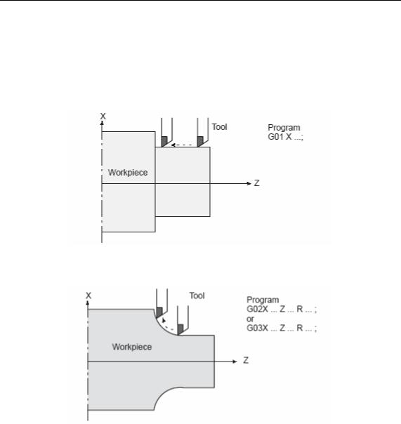
1.1.1 Tool movement along a straight line
Fig. 1.1.1 Tool movement along the straight line which is parallel to Z–axis
1.1.2 Tool movement along an arc
Fig. 1.1.2 Tool movement along an arc
1.1.3 Thread cutting
Threads can be cut by moving the tool in synchronization with spindle rotation.1 Straight thread cutting

PROGRAMMING 1 GENERAL 1 2
2 Taper thread cutting
The term interpolation refers to an operation in which the tool moves along a straight line or arc in the way described above.
Symbols of the programmed commands G01, G02, ... are called the preparatory function and specify the type of interpolation conducted in the control unit.
PROGRAMMING 1 GENERAL 1 3
1.2 FEED–FEED FUNCTION
Movement of the tool at a specified speed for cutting a workpiece is called the feed.
Feedrates can be specified by using actual numerics. For example, the following command can be used to feed the tool 150 mm/s——F150.
The function of deciding the feed rate is called the feed function(SeeII–6).
1.3 PART DRAWING AND TOOL MOVEMENT
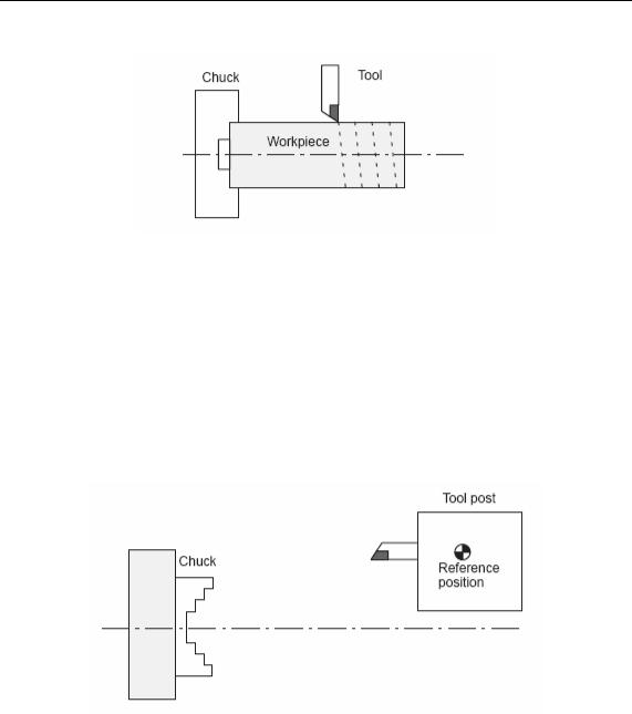
1.3.1 Reference position (Machine–Specific Position)
A CNC machine tool is provided with a fixed position. Normally, tool change and programming of absolute zero point as described later are performed at this position. This position is called the reference position.
The tool can be moved to the reference position in two ways:Manual reference position return
Automatic reference position return
1.3.2 Coordinate system on part drawing and coordinate system specified by CNC coordinate system

PROGRAMMING 1 GENERAL 1 4
The following two coordinate systems are specified at different locations:Coordinate system on part drawing
The coordinate system is written on the part drawing. As the program data, the coordinate values on this coordinate system are used.
Coordinate system specified by the CNC
The coordinate system is prepared on the actual machine tool. This can be achieved by programming the distance from the current position of the tool to the zero point of the coordinate system to be set.
The tool moves on the coordinate system specified by the CNC in accordance with the command program generated with respect to the coordinate system on the part drawing, and cuts a workpiece into a shape on the drawing.
Therefore, in order to correctly cut the workpiece as specified on the drawing, the two coordinate systems must be set at the same position.
PROGRAMMING 1 GENERAL 1 5
Methods of setting the two coordinate systems in the same position
The following method is usually used to define two coordinate systems at the same
location.
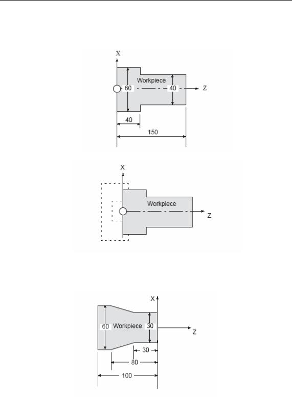
1. When coordinate zero point is set at chuck face
Fig. Coordinates and dimensions on part drawing
Fig. Coordinate system on lathe as specified by CNC (made to coincide with the coordinate system on part drawing)
2. When coordinate zero point is set at work end face.
Fig. Coordinates and dimensions on part drawing
PROGRAMMING 1 GENERAL 1 6
Fig. Coordinate system on lathe as specified by CNC
(made to coincide with the coordinate system on part drawing)
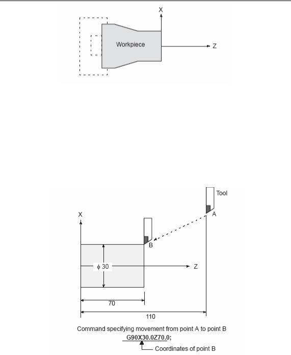
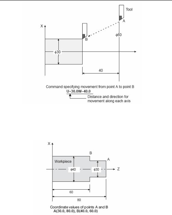
1.3.3How to indicate command dimensions for moving the tool absolute, incremental commands
Coordinate values of command for moving the tool can be indicated by absolute or
incremental designation (See II–9).Absolute commands
The tool moves to a point at ”the distance from zero point of the coordinate system” that is to the position of the coordinate values.
( ) Incremental comands
Specify the distance from the previous tool position to the next tool position.
PROGRAMMING 1 GENERAL 1 7
1.3.4 Diameter programming /radius programming
Dimensions of the X axis can be set in diameter or in radius. Diameter
programming or radius programming is employed independently in each machine. 1. Diameter programming
In diameter programming, specify the diameter value indicated on the drawing as the value of the X axis.
2. Radius programming
In radius programming, specify the distance from the center of the workpiece, i.e. the radius value as the value of the X axis.
PROGRAMMING 1 GENERAL 1 8
1.4 CUTTING SPEED –SPINDLE SPEED FUNCTION
The speed of the tool with respect to the workpiece when the workpiece is cut is called the cutting speed. As for the CNC, the cutting speed can be specified by the
spindle speed in rpm unit. EXAMPLE:
<When a workpiece 100 mm in diameter should be machined at a cutting speed of 80 mm/min. >
The spindle speed is approximately 250 rpm, which is obtained from N=1000v/_D. Hence the following command is required:S250
Commands related to the spindle speed are called the spindle speed function (See II–10)
The cutting speed v (m/min) can also be specified directly by the speed value. Even when the workpiece diameter is changed, the CNC changes the spindle speed so that the cutting speed remains constant.
This function is called the constant surface speed control function.
PROGRAMMING 1 GENERAL 1 9
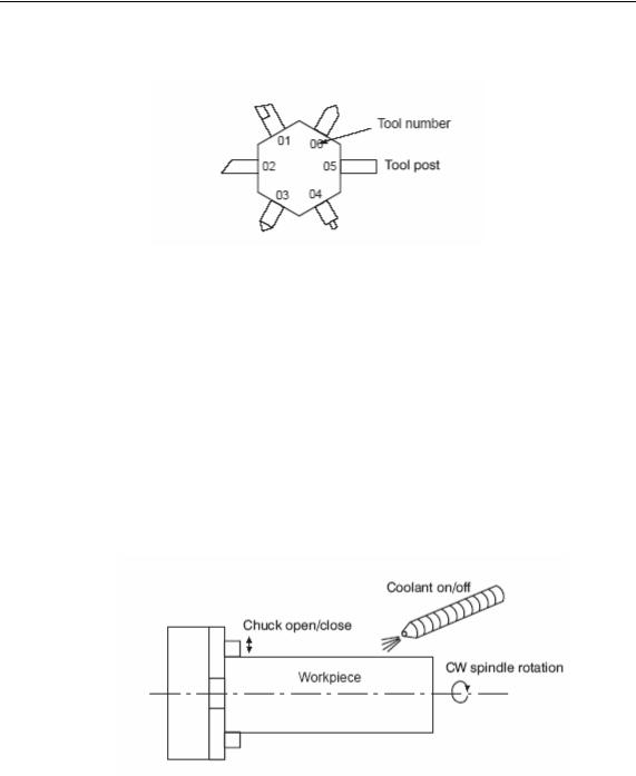
1.5SELECTION OF TOOL USED FOR VARIOUS MACHINING – TOOL
FUNCTION
When drilling, tapping, boring, milling or the like, is performed, it is necessary to select a suitable tool. When a number is assigned to each tool and the number is
specified in the program, the corresponding tool is selected. EXAMPLE:
<When No.01 is assigned to a roughing tool>
When the tool is stored at location 01 of the tool post, the tool can be selected by specifying T0101.
This is called the tool function.
1.6 COMMAND FOR MACHINE OPERATIONS MISCELLANEOUS FUNCTION
When machining is actually started, it is necessary to rotate the spindle, and feed coolant. For this purpose, on–off operations of spindle motor and coolant valve should be controlled.
The function of specifying the on–off operations of the components of the machine is called the miscellaneous function. In general, the function is specified by an M code. (See II–11)
For example, when M03 is specified, the spindle is rotated clockwise at the specified spindle speed.

PROGRAMMING 1 GENERAL 1 10
1.7 PROGRAM CONFIGURATION
A group of commands given to the CNC for operating the machine is called the program. By specifying the commands, the tool is moved along a straight line or an arc, or the spindle motor is turned on and off. In the program, specify the commands in the sequence of actual tool movements.
A group of commands at each step of the sequence is called the block.
The program consists of a group of blocks for a series of machining. The number for discriminating each block is called the sequence number, and the number for
discriminating each program is called the program number (See II–13.)
1.7.1Block
The block and the program have the following configurations.
Each block starts with a sequence number which identifies the block, and ends
with an end–of–block code which indicates the end of the block. This manual indicates the end–of–block code by ;

PROGRAMMING 1 GENERAL 1 11
1.7.2 Program
Normally, a program number is specified after the end–of–block (;) code at the beginning of the program, and a program end code M30 is specified at the end of the program.
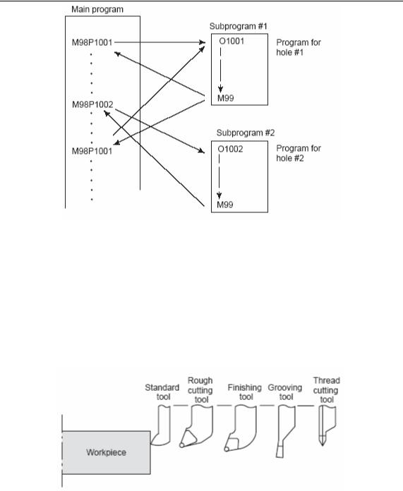
1.7.3 Main program and subprogram
When machining of the same pattern appears at many portions of a program, a program for the pattern is created. This is called the subprogram. On the other hand, the original program is called the main program. When a subprogram execution command appears during execution of the main program, commands of the subprogram are executed. When execution of the subprogram is finished, the sequence returns to the main program.
PROGRAMMING 1 GENERAL 1 12
1.8 TOOL COMPENSATION FUNCTION
1.8.1 Tool offset
Usually, several tools are used for machining one workpiece. The tools have different tool length. It is very troublesome to change the program in accordance with the tools.
Therefore, the length of each tool used should be measured in advance.
By setting the difference between the length of the standard tool and the length of each tool in the CNC (data display and setting : see III–15), machining can be performed without altering the program even when the tool is changed. This function is called tool length compensation.
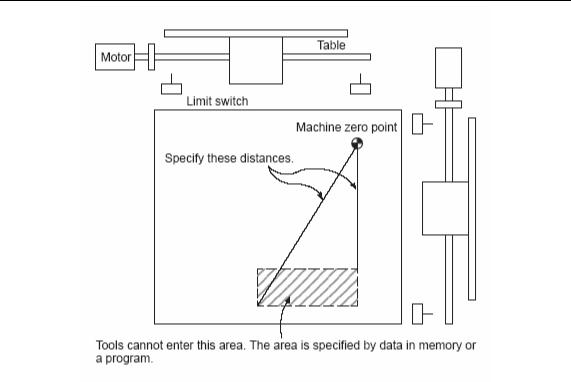
1.9 TOOL MOVEMENT RANGE—— STROKE
Limit switches are installed at the ends of each axis on the machine to prevent tools from moving beyond the ends. The range in which tools can move is called the stroke.
PROGRAMMING 1 GENERAL 1 13

PROGRAMNING 2(CONTROLLED AXES) 2 1
2.CONTROLLED AXES
2.1 CONTROLLED AXES
|
Number of controlled basic axes |
|
2 X Z |
|
|
||
|
Number of simultaneously controlled basic axes |
|
2 X Z |
|
|
||
2.2 SETTING UNIT |
|
|
|
|
|
|
|
|
|
|
|
|
|||
|
INPUT/OUTPUT |
Least input increment |
|
Least command increment |
|||
|
|
|
|
|
|||
|
|
X 0.001 mm (Diameter) |
|
X 0.0005 mm |
|||
|
Mm input |
Z 0.001 mm |
|
Z 0.001 |
mm |
||
|
Mm output |
X 0.001 mm Radius |
|
X 0.001 |
mm |
||
|
|
Z 0.001 mm |
|
Z 0.001 |
mm |
||
|
|
X 0.0001inch (Diameter) |
|
X 0.0005 mm |
|||
|
Inch input |
Z 0.0001inch |
|
Z 0.001 |
mm |
||
|
Mm output |
X 0.0001inch Radius |
|
X 0.001 |
mm |
||
|
|
Z 0.0001inch |
|
Z 0.001 |
mm |
||
|
|
X 0.001 mm Diameter |
|
X 0.00005inch |
|||
|
Mm input |
Z 0.001 mm |
|
Z 0.0001 inch |
|||
|
inch output |
X 0.001 mm Radius |
|
X 0.0001 inch |
|||
|
|
Z 0.001 mm |
|
Z 0.0001 inch |
|||
|
|
X 0.0001inch Diameter |
|
X 0.00005inch |
|||
|
inch input |
Z 0.0001inch |
|
Z 0.0001 inch |
|||
|
inch output |
X 0.0001inch Radius |
|
X 0.0001 inch |
|||
|
|
Z 0.0001inch |
|
Z 0.0001 inch |
|||
NOTE:
1 The unit in the table is a diameter value with diameter programming and a radius value in radius programming.
2 Least command increment is consisting of metric and inch input, and it is depending on the machine. The bit SCW of parameter №004 can select mm or inch. Mm and inch can not occur in the same program.
3 Setting unit refer to the machine tool’s description.
2.3 MAXIMUM STROKES
Maximum stroke=Least command increment×99999999
PROGRAMMING-3 (PREPARATORY FUNCTION) 3-1
3.PREPARATORY FUNCTION G FUNCTION
A number following address G determines the meaning of the command for the concerned block. G codes are divided into the following two types.
Type
One-shot G code
Modal G code
Meaning
The G code is effective only in the block in which it is specified.
The G code is effective until another G code of the same group is specified.
Example:
G01 and G00 are modal G codes in group 01.
G01X _;
Z _; G01 is effective in this range.
X _;
G00 Z_;
NOTE
1. Modal G codes have the following initial conditions when the power is turned on or the system is reset to the clear state.
1)Those G codes marked* in Table 3 are specified automatically.
2)G20 and G21 retain their original conditions.
3) G00 or G01 is automatically selected according to parameter setting.
2.The G codes of group 00 are one-shot G codes.
3.If a G code that does not appear in the G code list is specified, or a G code whose options are not supported is specified, alarm No. 010 is displayed.
4.Multiple G codes of different groups can be specified in a single block. When multiple G codes of one group are specified in a block, the G code specified last is effective.
5.G code can set the max speed of spindle in constant surface speed control.
6.A G code is displayed from each group.

PROGRAMMING-3 (PREPARATORY FUNCTION) 3-2
|
|
Table 3 G code list (1/2) |
|
G code |
Group |
Function |
|
|
|
|
|
G00 |
|
Positioning |
|
*G01 |
01 |
Linear interpolation |
|
G02 |
Circular interpolation CW |
||
|
|||
G03 |
|
Circular interpolation CCW |
|
G04 |
00 |
Dwell, Exact stop |
|
G10 |
Offset value setting |
||
|
|||
|
|
|
|
G20 |
04 |
Input in inch |
|
G21 |
Input in mm |
||
|
|||
|
|
|
|
G27 |
|
Reference position return check |
|
G28 |
00 |
Return to reference position |
|
|
|
||
G29 |
Return from reference position |
||
|
|||
G31 |
|
Skip function |
|
|
|
|
|
G32 |
01 |
Thread cutting |
|
G36 |
00 |
Automatic tool compensation X |
|
G37 |
Automatic tool compensation Z |
||
|
|||
*G40 |
|
Tool nose radius compensation cancel |
|
G41 |
07 |
Tool nose radius compensation left |
|
G42 |
|
Tool nose radius compensation right |
|
|
|
|
|
G43 |
|
Tool length compensation + direction |
|
G44 |
08 |
Tool length compensation - direction |
|
*G49 |
|
Tool length compensation cancel |
|
G50 |
00 |
coordinate system setting |
|
*G54 |
|
Workpiece coordinate system 1 selection |
|
G55 |
|
Workpiece coordinate system 2 selection |
|
G56 |
03 |
Workpiece coordinate system 3 selection |
|
G57 |
Workpiece coordinate system 4 selection |
||
|
|||
G58 |
|
Workpiece coordinate system 5 selection |
|
|
|
|
|
G59 |
|
Workpiece coordinate system 6 selection |
|
G65 |
00 |
Macro calling |
|
|
|
|

PROGRAMMING-3 (PREPARATORY FUNCTION) 3-3
|
|
Table 3 G code list(2/2) |
|
G code |
Group |
Function |
|
|
|
|
|
G68 |
06 |
Mirror image for X-axes ON |
|
|
|
||
*G69 |
Mirror image for X-axes OFF |
||
|
|||
|
|
|
|
G70 |
|
Finishing cycle |
|
G71 |
|
Stock removal in turning |
|
G72 |
00 |
Stock removal in facing |
|
|
|
||
G73 |
Pattern repeating |
||
|
|||
|
|
|
|
G74 |
|
Peck drilling on Z axis |
|
|
|
|
|
G75 |
|
Grooving on X axis |
|
G76 |
|
Multiple threading cycle |
|
|
|
|
|
G90 |
|
Outer diameter/internal diameter cutting cycle |
|
|
|
||
G92 |
01 |
Thread cutting cycle |
|
|
|||
G93 |
Tapping cycle |
||
|
|||
G94 |
|
End face turning cycle |
|
|
|
|
|
G96 |
02 |
Constant surface speed control ON |
|
|
|
||
*G97 |
Constant surface speed control OFF |
||
|
|||
|
|
|
|
G98 |
03 |
Per minute feed |
|
G99 |
Per revolution feed |
||
|
Loading...