

Page 1

CNC Series
KND—1000 TⅠ/1000 TⅡ CNC system for Lathe
USER’S MANUAL
Beijing KND CNC Technique Co. Ltd.
B12B-T00N-0101
KND LTD,2006
C
Page 2

CONTENTS
I GENERAL
1. GENERAL
1.1 GENERAL FLOW OF OPERATION OF CNC MACHINE TOOL
1.2 NOTES ON READING THIS MANUA
II PROGRAMMING
1. GENERAL
1.1 TOOL MOVEMENT ALONG WORKPIECE PARTS FIGURE-INTERPOLATION
1.2 FEED-FEED FUNCTION
1.3 PART DRAWING AND TOOL MOVEMENT
1.4 CUTTING FEED─SPINDLE SPEED FUNCTION
1.5 SELECTION OF TOOL USED FOR VARIOUS MACHINING-TOOL FUNCTION
1.6 COMMAND FOR MACHINE OPERATIONS MISCELLANEOUS FUNCTION
1.7 PROGRAM CONFIGURATION
1.8 TOOL COMPENSATION FUNCTION
1.9 TOOL MOVEMENT RANGE –STROKE
2. CONTROLLED AXES
2.1 CONTROLLED AXES
2.2 SETTING UNIT
2.3 MAXIMUM STROKES
3. PREPARATORY FUNCTION (G FUNCTION)
4. INTERPOLATION FUNCTIONS
4.1 POSITIONING (G00)
4.2 LINEAR INTERPOLATION (G01)
4.3 CIRCULAR INTERPOLATION (G02,G03)
5. THREAD CUTTING
5.1 THREAD CUTTING(G32)
5.2 unequal lead thread cuttingG34
6. FEED FUNCTION
6.1 RAPID TRAVERS
6.2 CUTTING FEEDRATE
6.3 AUTOMATIC ACCELERATION/DECELERATION
6.4 SPEED CONTROL AT COMERS OF BLOCKS
6.5 DWELL(G04)
7. REFERENCE POSITON
7.1 AUTOMATIC REFERENCE POINT TETURN(G28)
8. COORDINATE SYSTEM SETTING(G50)
……………………………………………………………………………………
……………………………………………………………………………………
……………………
L…………………………………………………
………………………………………………………………………
……………………………………………………………………………………
…………………………………………………………………
…………………………………………
……………………………………
…………………………………………………………
…………………………………………………
………………………………………………
……………………………………………………………………
……………………………………………………………………
……………………………………………………………………………
……………………………………………………………………
………………………………………
…………………………………………………………
……………………………………………………………………
………………………………………………………
……………………………………………
………………………………………………………………………
………………………………………………………………
……………………………………………………
………………………………………………………………………
………………………………………………………………………
…………………………………………………………………
…………………………………
……………………………………
……………………………………………………………………………
…………………………………………………………………
…………………………………
……………………………………………
…
…
……
1 - 0
1 - 1
1 - 1
1 - 2
1 - 0
1 - 1
1 - 2
1 - 4
1 - 3
1 - 9
1 - 10
1 - 10
1 - 11
1 - 13
1 - 13
2 - 1
2 - 1
2 - 1
2 - 1
3 - 1
4 - 1
4 - 1
4 - 2
4 - 2
5 - 1
5 - 1
5 - 6
6 - 1
6 – 1
6 - 1
6 - 3
6 - 4
6 - 5
7 - 1
7 - 1
8 - 1
Page 3

8.1 COORDINATE SYSTEM SETTING
8.2 COORDINATE SYSTEM SHIET
8.3 AUTOMATIC COORDINATE SYSTEM SETTING
8.4 WORK COORDINATE SYSTEM SHIFT
8.5 DIRECT MEASURED VALUE INPUT FOR WORK COORDINATE SYSTEM
SHIFT
………………………………………………………………………………………
9.COORDINATE VALUE AND DIMENSION
9.1 ABSOLUTE AND INCTEMENTAL PROGRAMMING
9.2 INCH/METRIC CONVERSION(G20,G21)
9.3 DECIMAL POINT PROGRAMMING/POCKET CALCULATOR TYPE DECIMAL
POINT PROGRAMMING
9.4 DIAMETER AND RADIUS PROGRAMMING
…………………………………………………………………
10. SPINDLE FUCTION(S FUCTION)
10.1 SPINDLE SPEED COMMAND
10.2 SIMULATING SPINDLE GEAR SHIFTING
10.3 CONSTANT SUREACE SPEED CONTROL(G96,G97)
10.4 CONTROLLING SPINDLE CHUCK
10.5 CONTROLLING TALSTOCK
10.6 SPINDLE ROTATION DWELL FUNCTION
11.TOOL FUNCTION (T FUNCTION)
11.1 TOOL-CHANGING PROCEDURE
11.2 FUNCTION FOR CHECKING INPUT SIGNAL OF TOOL CARRIER
11.3 SELECTING REAR TOOL CARRIER
11.4 PARAMETERS RELATIVE WITH TOOL CHANGING
12. MISCELLANEOUS FUNCTION
12.1 MISCELLANEOUS FUNCTION(M FUNCTION
12.2 USER INTERFACE GO TO FUNCTIONM CODE:M91/M92,M93/M94
12.3 SPECIAL M CODE:M21/M22,M23/M24
12.4 PARAMETERS OF MISCELLANE:M21/M22,M23/M24
13. PROGRAM CONFIGURATION
13.1 PROGRAMR
13.2 PROGRAM END
13.3 TABE END
……………………………………………………………………………
…………………………………………………………………………
………………………………………………………………………………
14. FUNCTIONS TO SIMPLIFY PROGRAMMING
14.1 CANNED CYCLE (G90,G92,G94.G93)
14.2 MULTIPLE REPETITIVE CYCLE(G70~G76)
14.3 CHAMFERING AND CORNER
15. COMPENSATION FUNCTION
……………………………………………………
………………………………………………………
……………………………………
………………………………………………
……………………………………………
…………………………………
……………………………………………
…………………………………………
……………………………………………………
………………………………………………………
…………………………………………
……………………………
……………………………………………………
…………………………………………………………
…………………………………………
……………………………………………………
……………………………………………………
…………………………………………………
………………………………
………………………………………………………
………………………………………
………………………………………………
……………………………
………………………………………………………
……………………………………
………………………………………………
…………………………………………
………………………………………………………
…………………………………………………………
……………
…………
8 - 1
8 - 1
8 - 2
8 - 3
8 - 4
9 - 1
9 - 1
9 - 3
9 - 3
9 - 5
10- 1
10- 1
10- 2
10- 4
10- 8
10- 8
10- 9
11- 1
11- 1
11- 2
11- 3
11- 3
12- 1
12- 1
12- 3
12- 4
12- 4
13- 1
13- 1
13- 7
13- 8
14- 1
14- 1
14-09
14-21
15- 1
Page 4

15.1 TOOLOFFSET
15.2 TOOL NOSE RADIUS COMPENSATION(G40 TO G42)
15.3 CHANGING OF TOOL OFFSET AMOUNT(PROGRAMMABLE DATE
INPUT)(G10)
……………………………………………………………………………………
…………………………………………………………………………
……………………………
16. MANUAL MEASURE INPUT OF TOOL COMPENSATION
16.1 OFFSET INPUT BY COUNTING
16.2 MEASURE INPUT
16.3 THE 2 WAYOF OFFSET INPUT
17. MEASURE FUNCTION
17.1 SKIP FUNCTION (G31)
17.2 ZUTOMATIC TOOL OFFSET(G36,G37)
………………………………………………………………………
…………………………………………………………………
…………………………………………………………………
18. WORKPIECE COORDINATE SYSTEM (G54~G59)
18.1 WORKPIECE COORDINATE SYSTEM
18.2 SHIFT OR CHANGE WORKPIECE COORDINATE SYSTEM(G10)
18.3 AUTOMATIC COOTDINATE SYSTEM SETTING
19. CUSTOM MACRO COMMAND
19.1 CUSTOM MACRO COMMAND
19.2 CUSTOME MACRO BODY
13.3 APPLICATION OF CUSTOM MACTOM MACRO
III OPERATION
1. GENERAL
1.1 MANUAL OPERATION
1.2 TOOL MOVEMENT BY PROGRAMING-AUTOMATIC OPERATION
1.3 AUTOMATIC OPERATION
1.4 TESTING A PROGRAM
1.5 EDITING A PART PROGRAM
1.6 DISPLAYING AND SETTING DATA
1.7 DISPLAY
1.8 DATA INPUT/OUTPUT
2. OPERATIONAL DEVICES
2.1 LCD/MDI PANEL
2.2 MACHINE TOOL OPERATIR’S PABEL
3. POWER ON / OFF
3.1 TUMING ON THE POWER
3.2 TURING OFF THE POWER
4. MANUAL OPERATION
4.1 MANUAL REFERENCE POSITION RETURN
4.2 JOG FEE
………………………………………………………………………………
………………………………………………………………………………………
…………………………………………………………………
………………………………………………………………
…………………………………………………………………
…………………………………………………………………………………
…………………………………………………………………
………………………………………………………………
………………………………………………………………………
……………………………………………………………………………
………………………………………………………………
……………………………………………………………………
…………………………………………………………………………………
………………………………………………………
……………………………………………………
……………………………………………
……………………………
………………………………………………
…………………………………
………………………………………………………
………………………………………………………
……………………………………………………………
……………………………………
…………………………………………………………
…………………………………………………
………………………………………………
……………………………………………………………
…………………………………………
……………………
……………
………………
15- 1
15- 4
15-40
16- 1
16- 1
16- 1
16- 2
17- 1
17- 1
17- 2
18- 1
18- 1
18- 2
18- 3
19- 1
19- 1
19- 1
19-10
1 - 0
1 - 1
1 - 1
1 - 2
1 - 3
1 - 4
1 - 7
1 - 8
1 -11
1 - 13
2 - 1
2 - 1
2 - 6
3 - 1
3 - 1
3 - 1
4 - 1
4 - 1
4 - 2
Page 5

4.3 STEP FEED
……………………………………
4.4 MANUAL HANDLE FEED (OPTIONAL FUNCTION)
4.5 MANUAL PROGRAM ZERO RETURN ZERO MODF
4.6 MANUAL ABSOLUTE ON/OFF
4.7 MANUAL AUXILIARY FUNCTION OPERATION
5. AUTOMATIC OPERATION
5.1 OPERATION MODE
5.2 AUTOMATIC OPERATION EXECUTION
5.3 AUTO OPERATION EXECUTION
5.4 STOPING AND TERMINATING AUROMATIC OPERATION
6. DRY RUN
6.1 ALL-AXIS MACHINE LOCK
6.2 AUXILIARY FUCTION LOCK
6.3 FEEDRATE OVERRIDE
6.4 RAPID TRAVERSE OVERRIDE
6.5 DRY RUN
6.6 SINGLE BLOCK
6.7 RESTART
6.8 OPTIONAL BLOCK SKIP
………………………………………………………………………………………
7. SAFTY OPERATION
7.1 EMERGENCY STOP
7.2 OVERTRAVEL
8. ALARM FUNCTION
9. PROGRAM STORAGE AND EDITING
9.1 PREPARATION
9.2 PROGRAM STORAGETO MEMORY
9.3 FILE INCLUDING MANY PROGRAMS STORED INTO MEMORY
9.4 PROGRAM SEARCH
9.5 DELETING PROGRAM
9.6 ALL PROGRAMS DELETING
9.7 PROGRAM OUTPUT
9.8 ALL PROGRAMS OUTPUT
9.9 SEQUENCE NUMBER SEARCH
9.10 PROGRAM COMPARATION BETWEEN IN MEMORY AND IN
PROGRAMMER
9.11 INSERTING, ALTERING AND DELETING A WORD
9.12 SEQUENCE NUMBER TO BE INSERTED AUTOMATICALLY
9.13 NUMBER OF REGISTERED PROGRAMS
………………………………………………………………………………
…………………………………
………………………………
…………………………………………………………
……………………………………
………………………………………………………………
………………………………………………………………………
………………………………………………
………………………………………………………
……………………………………………………………
……………………………………………………………
…………………………………………………………………
………………………………………………………
…………………………………………………………………………………
…………………………………………………………………………
……………………………………………
………………………………………………………………
………………………………………………………………………
……………………………………………………………………
……………………………………………………………………………
………………………………………………………………………
………………………………………………
……………………………………………………………………………
…………………………………………………
……………………………………………………………………
…………………………………………………………………
……………………………………………………………
……………………………………………………………………
……………………………………………………………
………………………………………………………
…………………………………………………………………………
………………………………
…………………………………………
………………………
………………
……………………
4 - 4
4 - 5
4 - 6
4 - 6
4 - 10
5 - 1
5 - 1
5 - 3
5 - 3
5 - 3
6 - 1
6 - 1
6 - 1
6 - 1
6 - 2
6 - 3
6 - 3
6 - 5
6 - 5
7 - 1
7 - 1
7 - 1
8 - 1
9 - 1
9 - 1
9 - 1
9 - 2
9 - 2
9 - 3
9 - 3
9 - 3
9 - 4
9 - 4
9 - 5
9 - 5
9 - 10
9 - 11
Page 6

9.14 STORAGE CAPACITY
10. DATA DISPLAY AND SET
10.1 OFFSET
10.2 SETTING THE SET PARAMETER
10.3 CUSTOM MACRO VARIABLES DISPLAY AND SETTING
10.4 PARAMETER
10.5 PITCH ERROR COMPENSATION DATA
10.6 DIAGNOSE AND PLC PARAMET
10.7 DISPLAY AND SET MACHINE SOFTWARE OPERATOR’S PANEL
11. DISPLAY
11.1 STATUS INDICATION
11.2 DATA KEYED IN DISPLAYING
11.3 SEQUENCE NUMBER AND PROGRAM NUMBER DISPLAY
11.4 PROGRAM MEMORY USAGE DISPLAY
11.5 COMMAND VALUE DISPLAY
11.6 CURRENT POSITION DISPLAY
11.7 RUNTIME AND PARTS COUNT DISPLAY
11.8 ALARM DISPLAY
11.9 INDEX DISPLAY
…………………………………………………………………………………
……………………………………………………………………………
……………………………………………………………………………………
12. DATA OUTPUT AND FLASH MEMORY
12.1 TOOL COMPENSATION
12.2 PARAMETER
12.3 FLASH MEMORY
……………………………………………………………………………
13. GRAPH FUNCTION
13.1 SET GRAPH PARAMETER
13.2 DESCRIPTIONPARAMETER
13.3 DESCRIPTION OF TOOL PATH
13.4 EXAMPLE
………………………………………………………………………………
14. UPPER LIMIT FEED
14.1 UPPER LIMIT FEED
14.2 SETTING RAPID TRAVERSE
14.3 SETTING ELECTRIC GEAR RATE N
14.4 SETTING ACCELERATION/DECELERATION TIME CONCTANT
14.5 PARAMETER SETTING
14.6 DRIVER ALARM
15. DESCRIPTION
15.1 STANDARD PARAMETER SETTING AND MEMORY CLEARING
15.2 NOT CHECK SOFT OVER TRAVEL
…………………………………………………………………………
……………………………………………………………………………
…………………………………………………………………
……………………………………………………………
……………………………………………………
……………………………………………
……………………………………………………
…………………………………………………………………
………………………………………………………
……………………………………………
…………………………………………………………
………………………………………………………
…………………………………………
………………………………………………………………………
………………………………………………………………………
……………………………………………
………………………………………………………………
………………………………………………………………………
………………………………………………………………………
……………………………………………………………
…………………………………………………………
………………………………………………………
………………………………………………………………………
……………………………………………………………………
…………………………………………………………
………………………………………………
………………………………………………………………
…………………………………………………
………………………
……………
……………………
………………
………………
9 - 11
10- 1
10 - 1
10 - 3
10 - 5
10 - 6
10 - 9
10 - 9
10 -10
11- 1
11 - 1
11 - 1
11 - 1
11 - 2
11 - 2
11 - 4
11 - 6
11 - 7
11 - 7
12 - 1
12 - 1
12 - 1
12 - 1
13 - 1
13 - 2
13 - 3
13 - 4
13 - 5
14 - 1
14 - 1
14 - 1
14 - 1
14 - 2
14 - 2
14 - 5
15 - 1
15 - 1
15 - 1
Page 7

15.3 BACKLASH COMPENSATION DESTIPTION
15.4 KEYBOARD AND INPUT SIGNAL FILTER
15.5 TURN ON THE POWER NOT TO ENTER NORMAL SCREEN
15.6 ROM PARITY ALARM,CMOSDATA LOSE, RAM CHECK
16. ILLUSTRATION OF USING U DISK (ⅡTYEP SYSTEM)
16.1 U DISK AND FILE SYSTEM
16.2 SYSTEMFUNCTION
IV CONNECTION
1. SYSTEM STRUCTURE
1.1 SYSTEM CONFIGURATION
1.2 INSTALLATION DIMENSION OF CNC CONTROL UNIT
1.3 ADDITIONAL OPERATOR’S PANEL DIMENSION
…………………………………………………………………………
……………………………………………………………………
2. INTERNAL CONNECTION
2.1 SYSTEM INTERNALCONNECTION DIAGRAM
2.2 POWER SOCKET SIGNAL ARRANGEMENT
2.3 CNC MAINBOARD SWITCH DESCRIPTION
3. EXTERNAL CONNECTION
3.1 SYSTEM EXTERNAL CONNECTION DIAGRAM
3.2 INTERFACE SIGNAL FROM CNC TO DRIVER
3.3 RS232-C STANDARD SERIES PORT
3.4 ANALOGUE SPINDLE INTERFACE CONNECTION
3.5 CONNECTION OF ADDITIONAL OPERATOR’S PANEL
3.6 OPTIONAL OPERATOR’S PANEL
3.7 Spindle coder CONNECTION …………………………………………………………
3.8 Connection of the Can bus interface …………………………………………………
…………………………………………………………
………………………………………………………………
……………………………………………………………
………………………………………………………………
……………………………………………………………
…………………………………………………
……………………………………………………
………………………………………
…………………………………………
…………………
…………………………
……………………
……………………………
…………………………………
………………………………………
…………………………………………
…………………………………………
……………………………………
………………………………………
…………………………………
…………………………
15 - 1
15 - 1
15 - 2
15 - 2
16 - 1
16-1
16-1
1 - 0
1 - 1
1 - 1
1 - 3
1 - 4
2 - 1
2 - 1
2 - 3
2 - 3
3 - 1
3 - 1
3 - 3
3 - 10
3 - 10
3 - 11
3 - 13
3 - 13
3 - 15
4. MACHINE TOOL INTERFACE
4.1 DESCRIPTION OF INPUT SIGNAL INTERFACE
4.2 DESCRIPTION OF OUTPUT SIGNAL INTERFACE
4.3 THE TABLE OF INPUT AND OUTPUT SIGNAL
4.4 DESCRIPTION OF INPUT AND OUTPUT SIGNAL
V APPENDIXES
APPENDIX 1 STORED PITCH ERROR COMPENSATON FUNCTION
APPENDIX2 G FUNCTION TABLE
APPENDIX3 TABLE OF RANGE OF COMMAND VALUE
APPENDIX4 BINARY AND DECIMAL CONVERSION
APPENDIX5 ALARM LIST
APPENDIX6 STATUS OF POWER ON, AT RESET
APPENDIX7 SPECIFION TABLE
……………………………………………………………………………
………………………………………………………………………
………………………………………………………
……………………………………
…………………………………
……………………………………
…………………………………
……………………………………………………………
…………………………………
………………………………………
…………………………………………
………………………………………………………………
……………………
4 - 1
4 - 1
4 - 3
4 - 5
4 -10
1 – 0
1 - 1
2 - 1
3 - 1
4 - 1
5 - 1
6 - 1
7 - 1
Page 8

APPENDIX8 PLC PARAMETER AND DIAGNOSE MESSAGE
1. DIAGNOSE DATA
2. PLC PARAMETER
APPENDIX9 PARAMETERS
APPENDIX10 OPERATION LIST
APPENDIX11 CNC STATUS DIAGNOSE MESSAGE
APPENDIX12 MACHINE DEBUG
12.1 TOOL SETTING
12.2 FUNCTION FOR STARTING AT ANY POINT
12.3 AKKITIONAL OPERATOT PANEL FOR MACHINE
12.4 FUNCTION OF SPINDLE PAUSE
12.5 FUNCTION FOR CHECKING INPUT SIGNAL OF TOOL HOLDER
APPENDIX13 INSTRUCTIONS OM KND COMMUNICATION SOFTWARE
………………………………………………………………………
…………………………………………………………………………
……………………………………………………………………
………………………………………………………………
…………………………………………
………………………………………………………………
…………………………………………………………………………
………………………………………
……………………………………………………
……………………………
…………………………………
………………
………………
8 - 1
8 - 5
8 - 5
9 - 1
10- 1
11- 1
12- 1
12- 1
12- 7
12-11
12-11
12-11
13- 1
Page 9

Overview Ⅰ -1(General) 1 - 0
I. OVERVIEW
Page 10

Overview Ⅰ -1(General) 1 - 1
SECTION I.OVERVIWE
1. GENERAL
K1000T achieves hi-speed and hi-accuracy control by using a 32-bit processor.
The screen is a monochrome 7.5″ LCD with resolution 640×480.
The main board is a 6-layer circuit board, with surface-mounted elements, and
customized FPGA, so that it is highly integrated, the whole unit has a reasonable
process structure, high interference immunity and reliability.
Full-Chinese operation interface, complete Help info, easy to operate.
Using G commands from international standard, compatible with FANUC system.
Completely new molded panel in internationally popular color, with elegant
appearance.
Super-strong program command processing capability, up to 10000 pieces/18sec,
can achieve hi-speed mini-line cutting.
With function for lead screw error compensation.
Hi-speed thread machining, rapid retreat.
Employing electronic disk, data will be saved in several positions, can restore
rapidly at an error.
Program memory with high capacity (640k byte).
DI/DO can be expanded freely by CAN bus. (Under development)
Type Ⅱ system has a interface for disk U, through which realizes saving
procedures between system and U disk mutually.
Type Ⅱ system panel does not contain the keys of machine tool, the user can
assemble by oneself or match the standard machine tool operator's panel.
This manual introduces the programming, operation and connection of KND 1000T
CNC system for drilling, boring, milling machines and machining centers.
This manual describes all optional functions of KND 1000T, in “specification list”
under appendices it has also introduced varied functions of the CNC system. Look up
the options incorporated into your system in the manual written by the machine tool
builder. Also look up the manual written by the machine tool builder for the specification,
operation for the operator’s panel.
K1000T system has following variety:
●K1000TA
monochrome LCD.
●K1000TB
color LCD.
: typeⅠ structure , panel dimension:400×306 , Using 7.4″
Ⅰ
: typeⅠ structure , panel dimension:400×306 , Using 7.5″
Ⅰ
Page 11
Overview Ⅰ -1(General) 1 - 2
●K1000TA
: typeⅡ structure , panel dimension:400×200 ,Using 7.4″
Ⅱ
monochrome LCD.
●K1000TD
: type
Ⅱ
structure , panel dimension:400×200 ,Using 8.4″
Ⅱ
TFT color LCD.
May select and match Machine tool Operator’s panel regarding K1000T system,
this panel apart two parts. the left part install the manual handle, the range selector,
emergency stop switch, the three-position switch, the circulation starting switch, the
power switch and so on; the right part is the machine tool keys, including 50 keys and
50 indicating lamps, when under the open style PLC system software, the key and the
lamp function may from the definition.
The difference between type
1. Panel dimension is different. type
2. type
without machine tool keys, may match independence machine tool
Ⅱ
and type Ⅱ structure is as follow :
Ⅰ
400×306
:
Ⅰ
type Ⅱ:400×200
,
operator’s panel .
3. type
system panel has USB and RS232
Ⅱ
interfaces.
The supplementary material of KND-1000T is as follows:
KND1000T USER’S MANUAL
Contain system programming, operation, connection and routine maintenance.
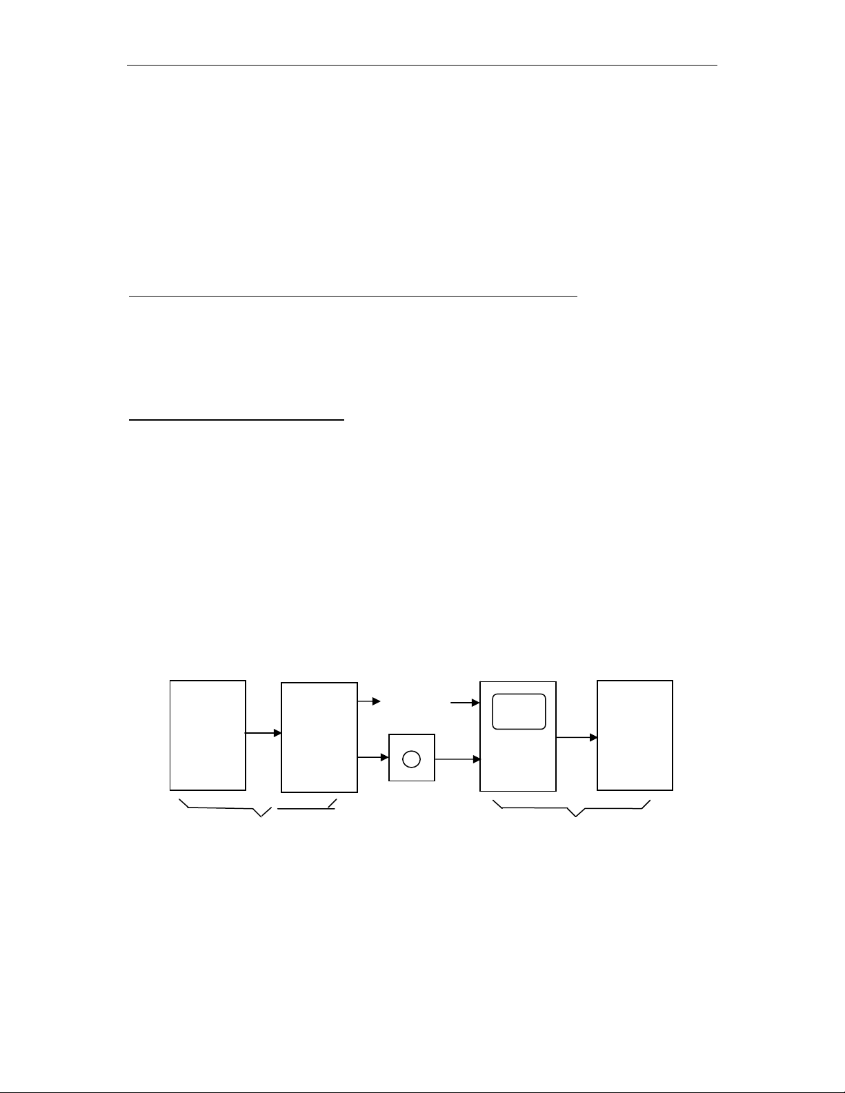
1.1 GENRAL FLOW OF OPERATION OF OPERATION OF CNC
MACHINE TOOL
When machining a part using the CNC machine tool, first prepares the program, and
then operates the CNC machine by using the program.
(1) First, prepare the program from a part drawing for cutting. How to prepare the
program is described in “II. PROGRAMMING”.
(2) The program is to be read into the CNC system. Then, mount the workpieces
and tools on the machine, and operate the tools according to the programming. Finally,
execute the machining actually.
How to operate the CNC system is described in “III. OPERATION”.
Part
drawing
Cutting
program
MDI/LCD
Machine
CNC
system
Disk
Refer to‘Programming’
Refer to‘Operation’
1.2 NOTES ON READING THIS MANUAL
The function of a CNC machine tool system depends not only on the CNC, but on
the combination of the machine tool, its magnetic cabinet, and driving system, etc. And
details about the function, programming, and operation relating to all combinations can
Page 12

Overview Ⅰ -1(General) 1 - 3
be determined only based on a concrete machine.
Option
function 1
. . .
Option
function N
CNC basic function
Interface
CNC system
From figure above one can see, a CNC system consists of basic function, optional
functions and interfaces, etc., different machines will have different optional functions
and interface designs. Please look up the manual from the machine builder.
(2) As mentioned above, KND 1000 CNC system is a universal system. This
manual provides a general description about various functions of the CNC system. For
a machine designer, in addition to read this manual, he shall also read the connection
manual, only in this way can he understand in an all-sided way the functions of the
system. And only based on above, can he give play to these functions optimally so that
the machine tool can reach its optimal performance. In addition, this manual is only a
description about functions, for a certain function, it is different on different machines,
and it’s impossible to present all examples for concrete use, so please do refer to the
manual from the machine builder.
(3) This manual is prepared based on system main board version 0012I-0000-
W01Z-0108, and system software version K1000TA
A01_060817.
Ⅰ
(4) As for the differences of systems with other software versions, please refer to
“Additional Description”.
(5)
If program the PLC procedure by yourself, please read 《PLC USERS
MANUAL》carefully.
★
Important:
K1000T system is of electronic disk function. After commissioning the machine,
please save current data of the system into the electronic disk. In this way, it is
possible to restore the system rapidly when current data of system is lost and becomes
disorder hence can’t work. As for the operating way please refer to “Operation 12-2”.
Page 13

Ⅱ PROGRAMMING -1(GENERAL) 1-0
Ⅱ PROGRAMMING
Page 14
Ⅱ PROGRAMMING -1(GENERAL) 1-1
1. GENERAL
1.1 TOOLMOVEMENT ALONG WORKPIECE PARTS
FIGURE——INTERPOLATION
The tool moves along straight lines and arcs constituting the workpiece parts figure
(See II-4).
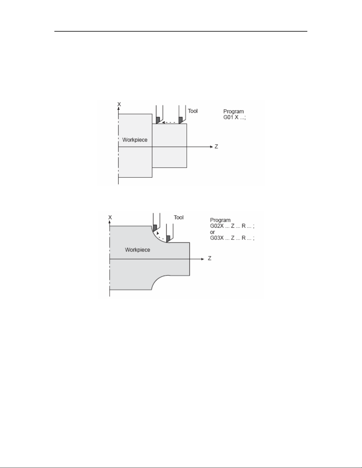
1.1.1 Tool movement along a straight line
Fig. 1.1.1 Tool movement along the straight line which is parallel to Z–axis
1.1.2 Tool movement along an arc
Fig. 1.1.2 Tool movement along an arc
1.1.3 Thread cutting
Threads can be cut by moving the tool in synchronization with spindle rotation.
(1) Straight thread cutting
Page 15
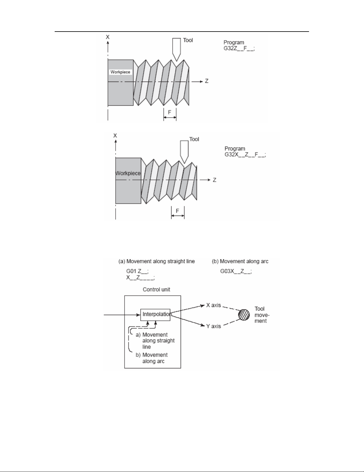
Ⅱ PROGRAMMING -1(GENERAL) 1-2
(2)Taper thread cutting
The term interpolation refers to an operation in which the tool moves along a
straight line or arc in the way described above.
Symbols of the programmed commands G01, G02, ... are called the preparatory
function and specify the type of interpolation conducted in the control unit.
Page 16
Ⅱ PROGRAMMING -1(GENERAL) 1-3
1.2 FEED–FEED FUNCTION
Movement of the tool at a specified speed for cutting a workpiece is called the
feed.
Feedrates can be specified by using actual numerics. For example, the following
command can be used to feed the tool 150 mm/s——F150.
The function of deciding the feed rate is called the feed function(SeeII–6).
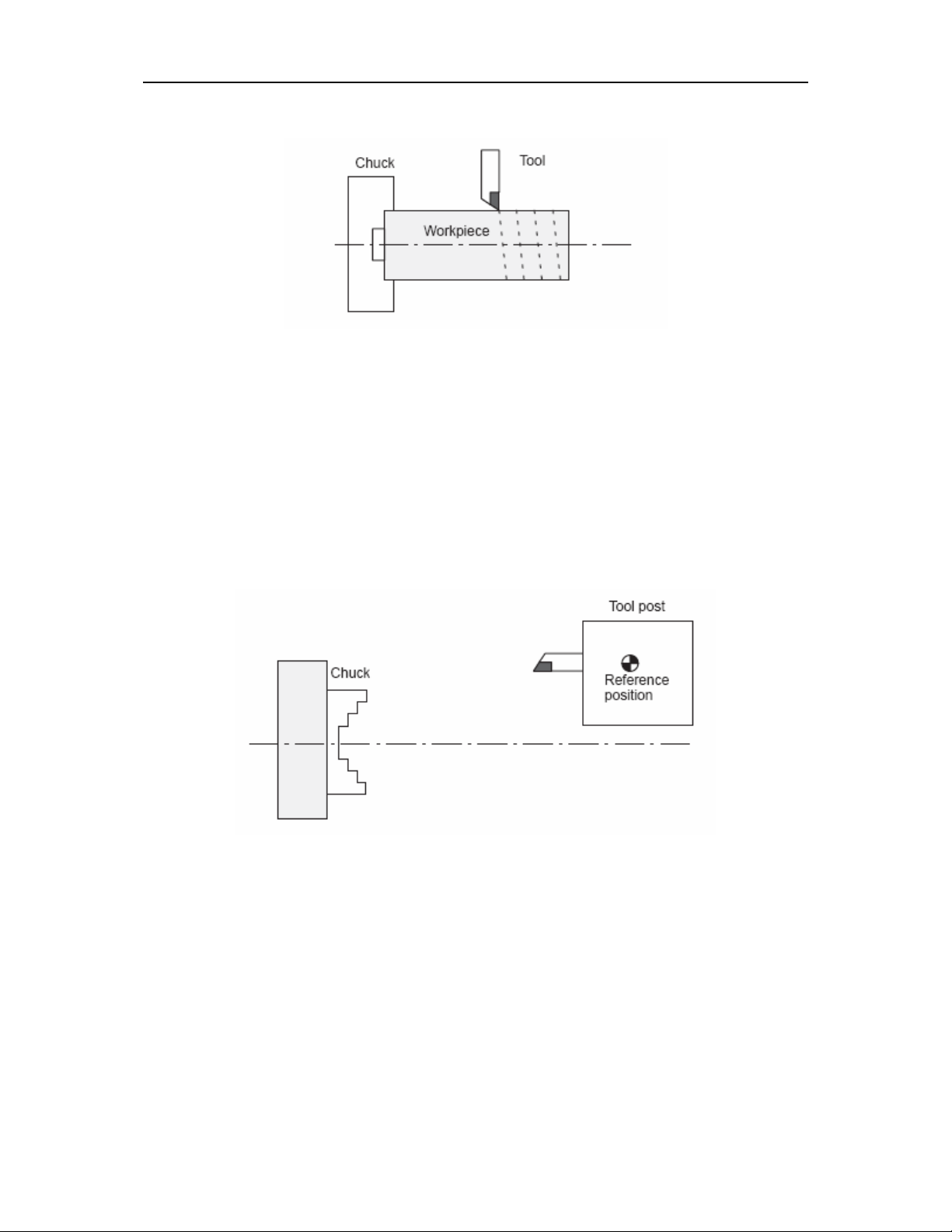
1.3 PART DRAWING AND TOOL MOVEMENT
1.3.1 Reference position (Machine–Specific Position)
A CNC machine tool is provided with a fixed position. Normally, tool change and
programming of absolute zero point as described later are performed at this position.
This position is called the reference position.
The tool can be moved to the reference position in two ways:
(Ⅰ)Manual reference position return
(Ⅱ)Automatic reference position return
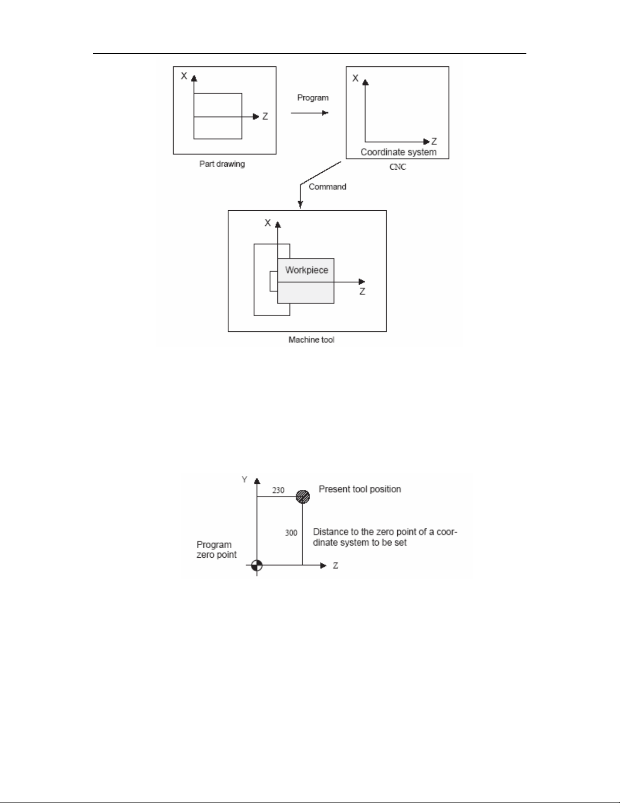
1.3.2 Coordinate system on part drawing and coordinate system
specified by CNC coordinate system
Page 17
Ⅱ PROGRAMMING -1(GENERAL) 1-4
The following two coordinate systems are specified at different locations:
ⅠCoordinate system on part drawing
The coordinate system is written on the part drawing. As the program data, the
coordinate values on this coordinate system are used.
Ⅱ Coordinate system specified by the CNC
The coordinate system is prepared on the actual machine tool. This can be
achieved by programming the distance from the current position of the tool to the zero
point of the coordinate system to be set.
The tool moves on the coordinate system specified by the CNC in accordance with
the command program generated with respect to the coordinate system on the part
drawing, and cuts a workpiece into a shape on the drawing.
Therefore, in order to correctly cut the workpiece as specified on the drawing, the
two coordinate systems must be set at the same position.
Page 18
Ⅱ PROGRAMMING -1(GENERAL) 1-5
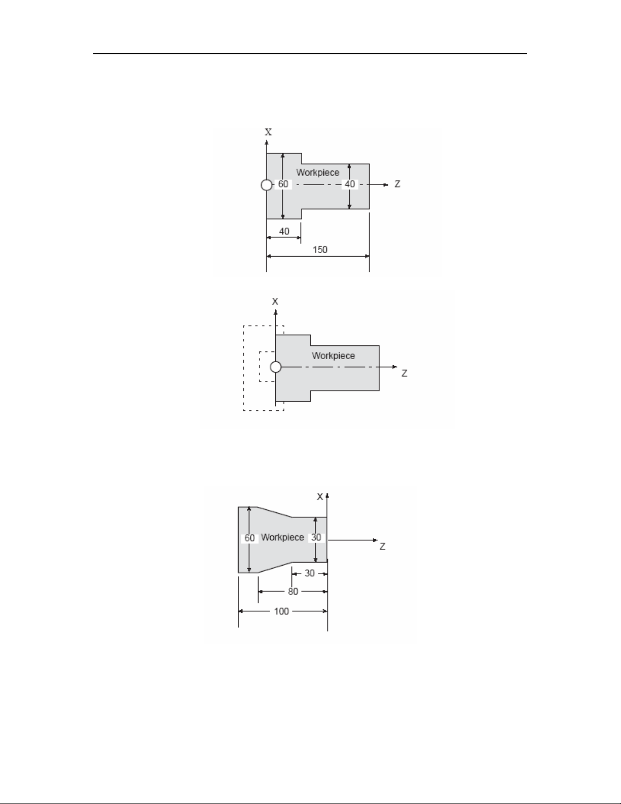
Methods of setting the two coordinate systems in the same position
The following method is usually used to define two coordinate systems at the same
location.
1. When coordinate zero point is set at chuck face
Fig. Coordinates and dimensions on part drawing
Fig. Coordinate system on lathe as specified by CNC
(made to coincide with the coordinate system on part drawing)
2. When coordinate zero point is set at work end face.
Fig. Coordinates and dimensions on part drawing
Page 19

Ⅱ PROGRAMMING -1(GENERAL) 1-6
Fig. Coordinate system on lathe as specified by CNC
(made to coincide with the coordinate system on part drawing)
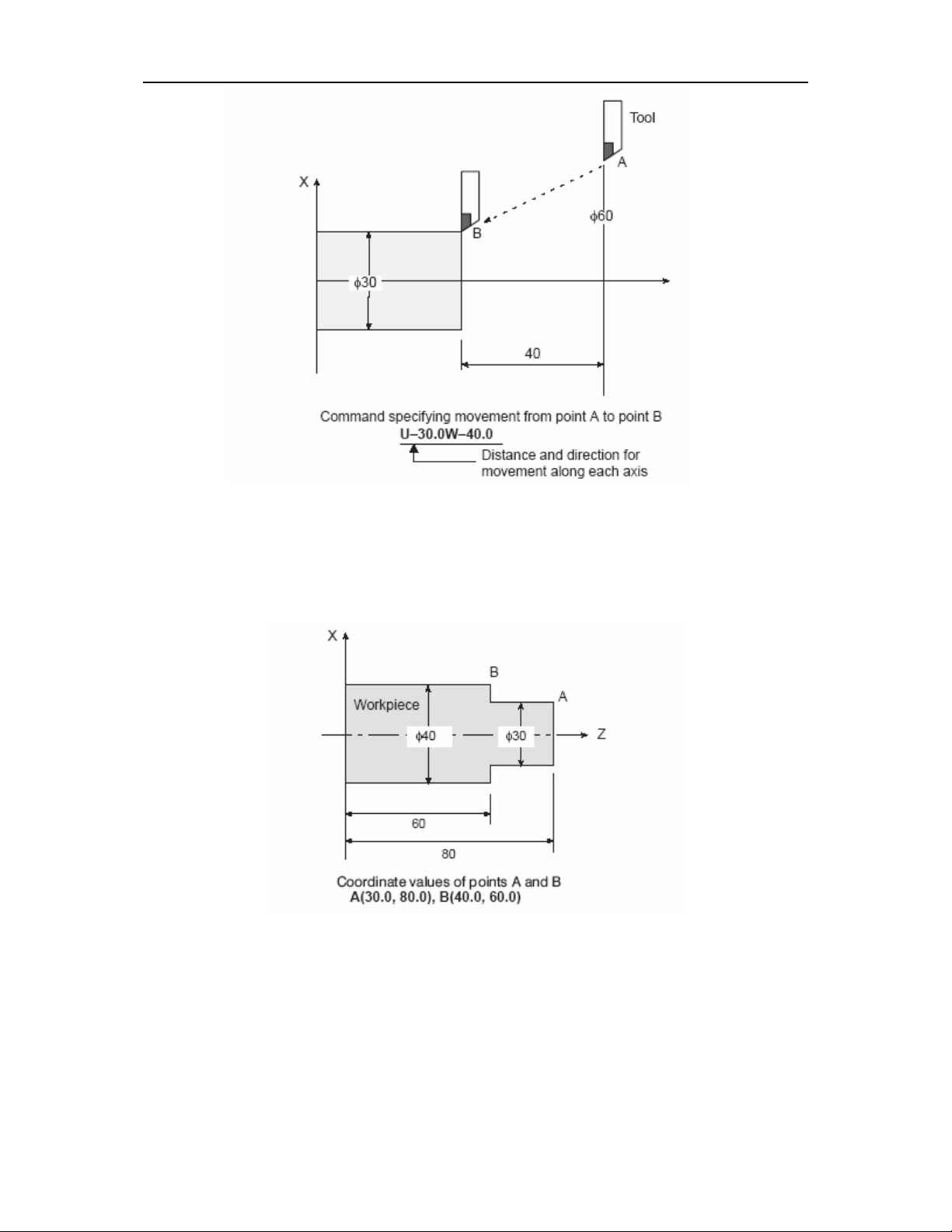
1.3.3 How to indicate command dimensions for moving the tool
absolute, incremental commands
Coordinate values of command for moving the tool can be indicated by absolute or
incremental designation (See II–9).
(Ⅰ)Absolute commands
The tool moves to a point at ”the distance from zero point of the coordinate
system” that is to the position of the coordinate values.
() Ⅱ Incremental comands
Specify the distance from the previous tool position to the next tool position.
Page 20
Ⅱ PROGRAMMING -1(GENERAL) 1-7
1.3.4 Diameter programming /radius programming
Dimensions of the X axis can be set in diameter or in radius. Diameter
programming or radius programming is employed independently in each machine.
1. Diameter programming
In diameter programming, specify the diameter value indicated on the drawing as
the value of the X axis.
2. Radius programming
In radius programming, specify the distance from the center of the workpiece, i.e.
the radius value as the value of the X axis.
Page 21
Ⅱ PROGRAMMING -1(GENERAL) 1-8
1.4 CUTTING SPEED –SPINDLE SPEED FUNCTION
The speed of the tool with respect to the workpiece when the workpiece is cut is
called the cutting speed. As for the CNC, the cutting speed can be specified by the
spindle speed in rpm unit.
EXAMPLE:
<When a workpiece 100 mm in diameter should be machined at a cutting speed of
80 mm/min. >
The spindle speed is approximately 250 rpm, which is obtained from N=1000v/_D.
Hence the following command is required:S250
Commands related to the spindle speed are called the spindle speed function (See
II–10)
The cutting speed v (m/min) can also be specified directly by the speed value.
Even when the workpiece diameter is changed, the CNC changes the spindle speed so
that the cutting speed remains constant.
This function is called the constant surface speed control function.
Page 22
Ⅱ PROGRAMMING -1(GENERAL) 1-9
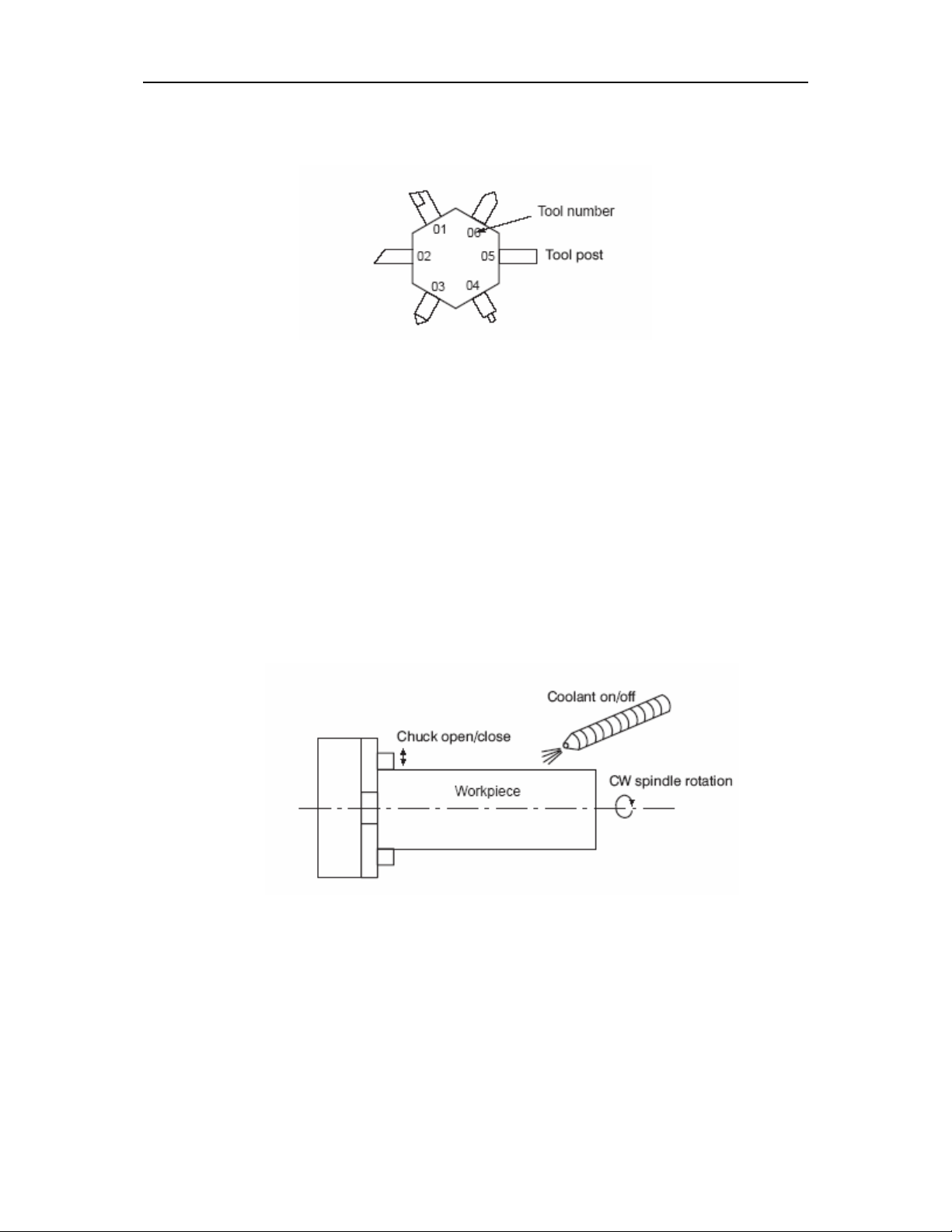
1.5 SELECTION OF TOOL USED FOR VARIOUS MACHINING –
TOOL
FUNCTION
When drilling, tapping, boring, milling or the like, is performed, it is necessary to
select a suitable tool. When a number is assigned to each tool and the number is
specified in the program, the corresponding tool is selected.
EXAMPLE:
<When No.01 is assigned to a roughing tool>
When the tool is stored at location 01 of the tool post, the tool can be selected by
specifying T0101.
This is called the tool function.
1.6 COMMAND FOR MACHINE OPERATIONS MISCELLANEOUS
FUNCTION
When machining is actually started, it is necessary to rotate the spindle, and feed
coolant. For this purpose, on–off operations of spindle motor and coolant valve should
be controlled.
The function of specifying the on–off operations of the components of the machine
is called the miscellaneous function. In general, the function is specified by an M code.
(See II–11)
For example, when M03 is specified, the spindle is rotated clockwise at the
specified spindle speed.
Page 23
Ⅱ PROGRAMMING -1(GENERAL) 1-10
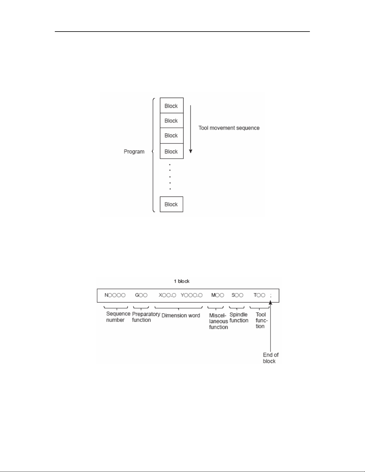
1.7 PROGRAM CONFIGURATION
A group of commands given to the CNC for operating the machine is called the
program. By specifying the commands, the tool is moved along a straight line or an arc,
or the spindle motor is turned on and off. In the program, specify the commands in the
sequence of actual tool movements.
A group of commands at each step of the sequence is called the block.
The program consists of a group of blocks for a series of machining. The number
for discriminating each block is called the sequence number, and the number for
discriminating each program is called the program
number (See II–13.)
1.7.1Block
The block and the program have the following configurations.
Each block starts with a sequence number which identifies the block, and ends
with an end–of–block code which indicates the end of the block.
This manual indicates the end–of–block code by ;
Page 24
Ⅱ PROGRAMMING -1(GENERAL) 1-11
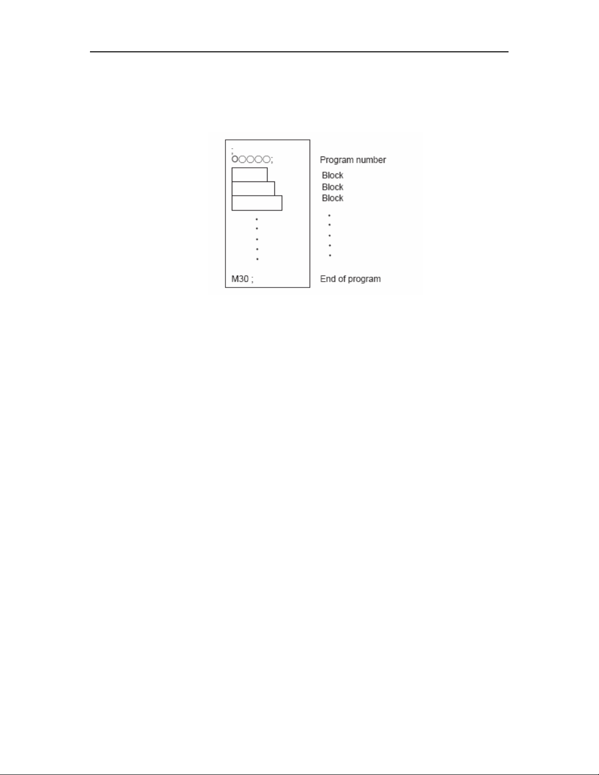
1.7.2 Program
Normally, a program number is specified after the end–of–block (;) code at the
beginning of the program, and a program end code M30 is specified at the end of the
program.
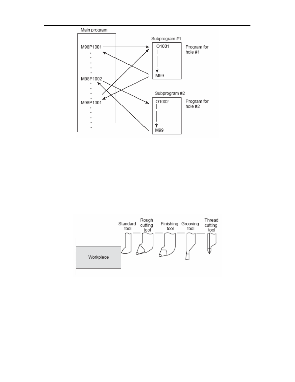
1.7.3 Main program and subprogram
When machining of the same pattern appears at many portions of a program, a
program for the pattern is created. This is called the subprogram. On the other hand,
the original program is called the main program. When a subprogram execution
command appears during execution of the main program, commands of the
subprogram are executed. When execution of the subprogram is finished, the
sequence returns to the main program.
Page 25
Ⅱ PROGRAMMING -1(GENERAL) 1-12
1.8 TOOL COMPENSATION FUNCTION
1.8.1 Tool offset
Usually, several tools are used for machining one workpiece. The tools have
different tool length. It is very troublesome to change the program in accordance with
the tools.
Therefore, the length of each tool used should be measured in advance.
By setting the difference between the length of the standard tool and the length of
each tool in the CNC (data display and setting : see III–15), machining can be
performed without altering the program even when the tool is changed. This function is
called tool length compensation.
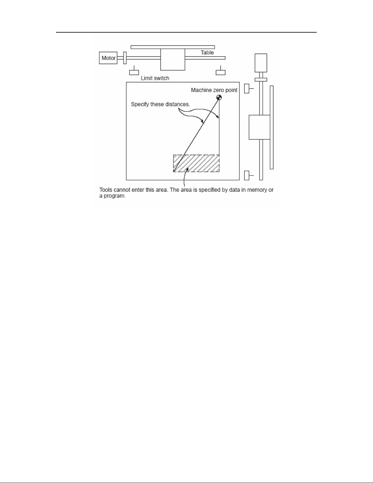
1.9 TOOL MOVEMENT RANGE—— STROKE
Limit switches are installed at the ends of each axis on the machine to prevent
tools from moving beyond the ends. The range in which tools can move is called the
stroke.
Page 26
Ⅱ PROGRAMMING -1(GENERAL) 1-13
Page 27

Ⅱ PROGRAMNING -2(CONTROLLED AXES) 2-1
2. CONTROLLED AXES
2.1 CONTROLLED AXES
Number of controlled basic axes
Number of simultaneously controlled basic axes
2.2 SETTING UNIT
INPUT/OUTPUT Least input increment Least command increment
X:0.001 mm (Diameter)
Z:0.001 mm
Mm output
Inch input
Mm output X:0.0001inch (Radius)
Mm input
inch output X:0.001 mm (Radius)
inch input
inch output X:0.0001inch (Radius)
NOTE:
X:0.001 mm (Radius)
Z:0.001 mm
X:0.0001inch (Diameter)
Z:0.0001inch
Z:0.0001inch
X:0.001 mm (Diameter)
Z:0.001 mm
Z:0.001 mm
X:0.0001inch (Diameter)
Z:0.0001inch
Z:0.0001inch
1、 The unit in the table is a diameter value with diameter programming and a
radius value in radius programming.
2、 Least command increment is consisting of metric and inch input, and it is
depending on the machine. The bit SCW of parameter №004 can select mm or
inch. Mm and inch can not occur in the same program.
3、 Setting unit refer to the machine tool’s description.
2.3 MAXIMUM STROKES
Maximum stroke=Least command increment×99999999
2(X,Z)
2(X,Z)
X:0.0005 mm
Z:0.001 mm Mm input
X:0.001 mm
Z:0.001 mm
X:0.0005 mm
Z:0.001 mm
X:0.001 mm
Z:0.001 mm
X:0.00005inch
Z:0.0001 inch
X:0.0001 inch
Z:0.0001 inch
X:0.00005inch
Z:0.0001 inch
X:0.0001 inch
Z:0.0001 inch
Page 28
Ⅱ PROGRAMMING-3 (PREPARATORY FUNCTION) 3-1
3. PREPARATORY FUNCTION(G FUNCTION)
A number following address G determines the meaning of the command for the
concerned block. G codes are divided into the following two types.
Type Meaning
One-shot G code
Modal G code
NOTE:
or the system is reset to the clear state.
whose options are not supported is specified, alarm No. 010 is displayed.
multiple G codes of one group are specified in a block, the G code specified last is
effective.
Example:
G01 and G00 are modal G codes in group 01.
G01X _;
Z _; G01 is effective in this range.
X _;
G00 Z_;
1. Modal G codes have the following initial conditions when the power is turned on
1) Those G codes marked* in Table 3 are specified automatically.
2) G20 and G21 retain their original conditions.
3) G00 or G01 is automatically selected according to parameter setting.
2. The G codes of group 00 are one-shot G codes.
3. If a G code that does not appear in the G code list is specified, or a G code
4. Multiple G codes of different groups can be specified in a single block. When
5. G code can set the max speed of spindle in constant surface speed control.
6. A G code is displayed from each group.
The G code is effective only in the block in which it
is specified.
The G code is effective until another G code of the
same group is specified.
Page 29

Ⅱ PROGRAMMING-3 (PREPARATORY FUNCTION) 3-2
Table 3 G code list (1/2)
G code
G00
*G01
Group Function
Positioning
Linear interpolation
01
G02
G03
Circular interpolation CW
Circular interpolation CCW
G04 Dwell, Exact stop
00
G10
Offset value setting
G20 Input in inch
04
G21
G27
Input in mm
Reference position return check
G28 Return to reference position
00
G29 Return from reference position
G31
G32 01
Skip function
Thread cutting
G36 Automatic tool compensation X
00
G37
Automatic tool compensation Z
*G40
G41 Tool nose radius compensation left
07
G42
G43
G44
08
*G49
G50 00
*G54
G55
G56
G57 Workpiece coordinate system 4 selection
03
G58
G59
Tool nose radius compensation cancel
Tool nose radius compensation right
Tool length compensation + direction
Tool length compensation - direction
Tool length compensation cancel
coordinate system setting
Workpiece coordinate system 1 selection
Workpiece coordinate system 2 selection
Workpiece coordinate system 3 selection
Workpiece coordinate system 5 selection
Workpiece coordinate system 6 selection
G65 00 Macro calling
Page 30

Ⅱ PROGRAMMING-3 (PREPARATORY FUNCTION) 3-3
Table 3 G code list(2/2)
G code
G68
Group Function
Mirror image for X-axes ON
06
*G69
G70
G71
Mirror image for X-axes OFF
Finishing cycle
Stock removal in turning
G72 Stock removal in facing
G73
00
G74
G75
G76
G90
G92
Pattern repeating
Peck drilling on Z axis
Grooving on X axis
Multiple threading cycle
Outer diameter/internal diameter cutting cycle
Thread cutting cycle
01
G93
G94
Tapping cycle
End face turning cycle
G96
Constant surface speed control ON
02
*G97
G98
Constant surface speed control OFF
Per minute feed
03
G99
Per revolution feed
Page 31

PROGRAMMINGⅡ -4 (INTERPOLATION FUNCYION) 4- 1
(
4. INTERPOLATION FUNCTIONS
4.1 POSITIONING(G00)
The G00 command moves a tool to the position in the workpiece system specified
with an absolute or an incremental command at a rapid traverse rate. In the absolute
command, coordinate value of the end point is programmed. In the incremental
command the distance the tool moves is programmed.
Format
G00 IP _;
IP _: For an absolute command, the coordinates of an end position, and for an
incremental command, the distance of the tool moves.
Tool path generally does not become a straight line.
EXAMPLE
NOTE:
The rapid traverse rate in the G00 command is set by the parameter No. 038 to
040 for each axis independently by the machine tool builder. The rapid traverse rate
cannot be specified in the address F. Feed rate specified by address F is valid.
X
Z
X
(diameter)
Z
Non liner positioning.
36.0
56.0
30.0
diameter)
G00 X40.0 Z56.0 ;or
40.0
Z
G00 U60.0 W-36.0 ;
Page 32

PROGRAMMINGⅡ -4 (INTERPOLATION FUNCYION) 4- 2
4.2 LINEAR INTERPOLATION (G01)
Format
G01 IP _F_;
IP _: For an absolute command, the coordinates of an end position, and for an
incremental command, the distance of the tool moves.
F_; Speed of tool feed (Feedrate)
A tools move along a line to the specified position at the feedrate specified in F.
The feedrate specified in F is effective until a new value is specified. It need not be
specified for each block. The command X and Z is absolute command and U and W is
incremental command.
G01 Xα Zβ F f
α
Feed rate of X-axis direction:
Feed rate of Z-axis direction: f
L =
22
βα
+
F
x
F ×=
z
f=×
L
β
L
4.3 CIRCULAR INTERPOLATION(G02, G03)
The command below will move a tool along a circular arc.
G02 R_
X_ Z_
G03 I_ K_
F_;
Page 33

PROGRAMMINGⅡ -4 (INTERPOLATION FUNCYION) 4- 3
Date to be given command meaning
1 Rotation direction
G02 Clockwise direction CW
G03 Counterclockwise direction CCW
X、Z
U、W
End point position in the work
coordinate system
Distance from start point to
2
absolute
End point
incremental
end point
Distance from start
3
point to center
Radius of arc R
I、K
Distance with direction from
start point to arc center.(radius
command)
4 feedrate F Federate along the arc
The clockwise or counterclockwise direction varies in right or left hand coordinate
systems.
X
Z
G03
G02
G02
G03
Z
Right hand
X
Left hand
The end point an arc is specified by address X, Z or U, W, and is expressed as an
absolute or incremental value. For the incremental value, the coordinate of the end
point which is views from the start point of the arc is specified. The arc center is
Page 34

PROGRAMMINGⅡ -4 (INTERPOLATION FUNCYION) 4- 4
specified by address I and K for the X and Z axis, respectively. The numerical value
following I, K, however, is a vector component in which the arc center is seen from the
start point, and is always specified as an incremental value as shown in the figure.
End point(Z,X)
center
K
Start point
I
I and K must be as signed according to the direction. The radius can be specified
with address R instead of specifying the center by I or K. the command format is as
follows:
G02
G03
In this case, two types of arcs (one arc is less than 180°; the other is more than
180°) are considered, as shown in the figure below.
X_ Z_ R_ F_ ;
Page 35

PROGRAMMINGⅡ -4 (INTERPOLATION FUNCYION) 4- 5
EXAMPLE
X
15.0
R25.0
Φ50.0
Φ30.0
Z
30.0
50.0
G02 X50.0 Z30.0 I35.0 F30; or
G02 U20.0 W-20.0 I35.0 F30; or
G02 X50.0 Z30.0 R25.0 F30; or
G02 U20.0 W-20.0 R25.0 F30;
The feed speed of the circular interpolation is specified by F, and it is the speed of tool
along circular tangent.
NOTE:
1、 I0 and K0 can be omitted.
2、 If X and Z are both omitted or if the end point is located at the same position
as the start point, and when the center is commanded by I and K, an arc of
360° (a complete circle) is assumed.
G02 I_ ; (a completer circle)
When R is used, an arc of 0° is programmed:
G02 R_ ; (the cutter does not move)
3、 The error between the specified federate and the actual tool federate is ±2%
or less. However , this federate is measured along the arc after the tool
mose R compensation is applied.
4、 If I ,K and R addressed are specified simultaneously, the arc specified by
address R takes precedence and the others are ignored.
5、 If I or K is used, the difference in the radius values at the start and end
points of an arc does not cause an alarm.
Page 36

Ⅱ PROGRAMMING -5(THREAD CUTTING) 5-1
5. THREAD CUTTING(G32,G34)
5.1 THREAD CUTTING (G32)
Tapered screws and scroll threads in addition to equal lead straight threads can
be cut by using a G32 command.
FORMAT
G32IP_F_;
IP_: End point
F_: Lead of the long axis (always radius programming)
EXAMPLE
G32 X__ Z__ F__ ;
L
L
In general, thread cutting is repeated along the same tool path from rough cutting
to finish cutting for a screw. Since thread cutting starts when the position coder
mounted on the spindle outputs a 1–turn signal, threading is started at a fixed point and
the tool path on the workpiece is unchanged for repeated thread cutting. Note that the
spindle speed must remain constant from rough cutting to finish cutting. If not, incorrect
thread lead will occur.
Page 37

Ⅱ PROGRAMMING -5(THREAD CUTTING) 5-2
X
The thread lead must be specified as a radius value.
In general, the lag of the servo system, etc. will produce somewhat incorrect leads
at the starting and ending points of a thread cut. To compensate for this, a threading
length somewhat longer than required should be specified.
Lead command range
Metric input
Inch input
0.0001~500.0000 MM
0.000001~50.000000 INCH
EXAMPLE
δ2
30mm
δ1
Z
70mm
The following values are used in programming :
Thread lead: 4mm
δ1=3mm
δ2=1.5mm
Depth of cut : 1mm (cut twice)
(Metric input, Diameter programming)
G00 U– 62.0;
G32 W–74.5 F 4.0;
G00 U 62.0;
W 74.5;
U–64.0;
(For the second cut, cut 1mm more)
Page 38

Ⅱ PROGRAMMING -5(THREAD CUTTING) 5-3
X
G32 W–74.5;
G00 U64.0;
W74.5;
Φ50.0
Φ43.0
δ2
30mm
40mm
The following values are used in programming:
Thread lead: 3.5mm in the direction of the Z axis
δ1=2mm
δ2=1mm
Cutting depth in the X axis direction is 1mm
(Cut twice)
(Metric input, Diameter programming)
G00 X12.0 Z72.0;
G32 X41.0 Z29.0 F3.5;
G00 X50.0 Z72.0;
X10.0; (For the second cut, cut 1mm more M)
G32 X39.0 Z29.0;
G00 X50.0 Z72.0;
NOTE:
1、 Feed rate override is effective (fixed at 100%) during thread cutting.
2、 It is very dangerous to stop feeding the thread cutter. This will suddenly
increase the cutting depth. Thus, the feed hold function is ineffective while
thread cutting. If the feed hold button is pressed during thread cutting, the
tool will stop after a block not specifying thread cutting is executed as if the
SINGLE BLOCK button were pushed. However, the feed hold lamp (SPL
lamp) lights when the FEED HOLD button on the machine control panel is
pushed. Then, when the tool stops, the lamp is turned off (Single Block stop
status).
δ1
Z
Φ14.0
Page 39

Ⅱ PROGRAMMING -5(THREAD CUTTING) 5-4
3、 When the FEED HOLD button is again pushed during the first block not
specifying thread cutting just after thread cutting block or when it has been
continuously pushed, the tool stops at the block not specifying thread cutting.
4 、When thread cutting is executed in the single block status, the tool stops after
execution of the first block not specifying thread cutting.
5、 When the mode was changed from automatic operation to manual operation
during thread cutting, the tool stops at the first block not specifying thread
cutting as when the feed hold button is pushed as mentioned in Note 3.
However, when the mode is changed from automatic mode to another, the tool
as a single block mode will stop after execution of the block not specifying
thread cutting like in Note 4.
6 、 When the previous block was a thread cutting block, cutting will start
immediately without waiting for detection of the 1–turn signal even if the
present block is a thread cutting block. However, the lead at the point where
the blocks join is incorrect. To obtain the correct lead, the continuous
threading option is required.
G32Z _ F_;
Z _; (A 1–turn signal is not detected before this block.)
G32; (Regarded as threading block.)
Z_ F_; (One turn signal is also not detected.)
7、 Because the constant surface speed control is effective during scroll thread or
tapered screw cutting and the spindle speed changes, the correct thread lead
may not be cut. Therefore, do not use the constant surface speed control
during thread cutting.
8 、 A movement block preceding the thread cutting block must not specify
chamfering or corner R.
9、 A thread cutting block must not specifying chamfering or corner R.
10、The spindle speed override is effective in thread cutting mode.
11、Spindle override is valid in thread cutting. If the override is changed, incorrect
thread will generate due to acc./dec. rate.
5.1.1 INCH THREAD CUTTING FUNCTION
Page 40

Ⅱ PROGRAMMING -5(THREAD CUTTING) 5-5
Thread lead is specified by F code in thread cutting G32 and G92. If address I is
specified instead of F, the unit of I is lead per inch.
Command range : 0.060~254000.000 lead/inch.
NOTE:
1、 If I and F are both specified at the same program, F is valid.
2、 Decimal point is allowed in program, the unit of address I is 0.001lead/inch,
eg. I16=0.016lead/inch
I16=16lead/inch
3、 F is calculated automatically when I is commanded
F = 25.4×1000/I (unit: 0.0001 mm/rev)
4 bits behind the decimal is valid.
eg. When F = 2.86764, F = 2.8676 is valid.
When F = 2.86765, F = 2.8677 is valid
1
(1) Cutting thread is
(2) Cutting thread
50
lead/inch, I2.125 (or I2125) is specified.
2
8
4
lead/inch, I50.8 (or I50800) is specified.
5
(3) Cutting thread 6 lead/inch, I = 6 (or I6000) is specified.
5.1.2 START ANGLE OFFSET IN THREAD CUTTING
FORMAT
G32 X_ Z_ F_ Q_;
Q: offset angle, 0~360
Multi-lead thread will be cut after the offset Q angle is specified in Multi-lead
thread cutting.
NOTE
:
1、Q is only valid in specified block.
2、It is invalid if it exceeds 360, zero will be set to Q.
3、Q is only valid in the first G32 block when many G32 commands are
specified.
5.2 unequal lead thread cutting—G34
The increase or the decrease can be set in every thread cutting, in this way
Page 41

Ⅱ PROGRAMMING -5(THREAD CUTTING) 5-6
unequal lead thread cutting is finished.
Format: G34 IP_ F_ K_;
IP_ : End point
F_ : Thread lead of long axis at jumping-off point
K _ : Increase or the decrease in every thread cutting of spindle
Explanation:
The addresses except K are the same as straight thread and tapered screws in G32.
The range of K:
metric input: ±0.0001~±500.0000mm/turn
Inch input : ±0.000001~±9.999999inch/turn
When K exceeds this range, and thread lead exceeds permission or thread lead
becomes minus due to the increase or decrease of K, P/S alarm No.1
4 will generate.
5.2.1 multi- pitch unequal lead thread cutting
The following command can machining multi-pitch unequal lead thread. Q is the
same with the one in G32.
Format: G34 IP_ F_ K_ Q_
Warning:
The escaping function of thread cutting is invalid in G34.
If thread lead is too much larger, the rotate speed should be set smaller. Or the
calculated feed speed may exceed the upper limit of the feed speed (parameter No.45);
here system will automatically move at the rate of the upper limit, which will result in
machining incorrect thread lead.
Example:
The thread lead at jumping-off point: 8.0mm
The increase of the thread lead: 0.5mm/ turn
G34 Z-36.0 F8.0 K0.5;
Page 42

Ⅱ PROGRAMMING-6 (FEED FUNCTION) 6 - 1
A
6. FEED FUNCTION
6.1 RAPID TRAVERSE
The positioning command (G00) positions the tool by rapid traverse. A rapid
traverse rate is set for each axis by parameter No. 038to 040, so no rapid traverse
feedrate need be programmed.
The following overrides can be applied to a rapid traverse rate with the switch on
the machine operator’s panel:
F0, 25, 50, 100%
F0: Allows a fixed feedrate to be set for each axis by parameter No. 051
For detailed information, refer to the appropriate manual of the machine tool
builder.
6.2 CUTTING FEEDRATE
Feedrate of linear interpolation (G01), circular interpolation (G02, G03), and etc. re
commanded with numbers after the F code.
The unit of F code is mm/min or inch/min.
6.2.1 Tangential speed constant control
Cutting feed is controlled so that the tangential feedrate is always set at a specified
feedrate.
Cutting feed usually controls the speed of tangential direction and makes it come
to the instruction speed.
X
F
F
Start poing
X
F
Z
F: tangential feedrate
FX: X-axis feedrate
FZ: Z-axis feedrate
6.2.2 Cutting feedrate clamp
End point
Z
2
X FFF +=
Z
2
X
Start poing
rc interpolation
F
Z
F
X
F
End point
Z
Page 43

Ⅱ PROGRAMMING-6 (FEED FUNCTION) 6 - 2
Cutting feedrate upper limit can be set as parameter №.045. if the actual cutting
feedrate (feed rate with override) is commanded exceeding the upper limit it is clamped
to a speed not exceeding the upper limit value.
The clamped values are set in mm/min or inch/min.
Except during acceleration or deceleration, the CNC arithmetic error for the
command value of the feed rate is within ±2%. This error is applied to the time
measured for the tool to move a distance of 500mm or more under stationary
conditions.
6.2.3 Feed rate override
Feedrate can be overridden by a switch located on operator’s panel, from 0 to
150% (step 10%).
6.2.4 Feed per minute(G98)
With the feed per minute mode G98, tool feed rate per minute is directly
commanded by numerical value after F code.
G98 is model. Once commanded, it is effective until G99(per revolution feed) is
commanded.
6.2.5 Feed per revolution(G99)
Specify feed per revolution mode by G99. following F, directly specify the feed of
tool per spindle revolution. It is necessary to mount a position coder on the spindle.
G99 is modal. After G99 is specified, it is effective until G98per minute feed) is
commanded.
Table 6.2.5 feed per minute and revolution
Feed per minute Feed per revolution
Designated address F F
Designated G code G98 G99
Range of
designation
Clamping value
Override
Mm input
Inch
input
1~15000mm/min
(F1~F15000)
0.01~600.00inch/min
(F1~F60000)
Clamping takes place at a certain specific speed for both
feed per minute and feed per revolution.
The clamping value is set by the machine tool builder.
(override is applied to implement clamping of speed.)
For both feed per minute and feed per revolution, 0 to
150% override can be applied (in increments of 10%)
0.0001~500.0000mm/rev
(F1~F5000000)
0.000001~50.000000inch/rev
(F1~F9999999)
Page 44

Ⅱ PROGRAMMING-6 (FEED FUNCTION) 6 - 3
NOTE:
1、 when the rotation speed of the position coder is 1 rpm or less, the feed rate
becomes no uniform. In cases where machining is not adversely affected by
feed rate no uniformity , the position coder can be used at 1 rpm or less.
Though the degree of no uniformity differs according to the case, the degree
becomes large as the rotation speed becomes low less than 1 rpm.
2、 G98 and G99 are modal; once they are commanded, they are effective until
another code appears.
3、 The error from the standpoint of the CNC operation with respect to the
command value of the federate is ±2%. After the feed rate has attained its
rated value, the time required to move over a distance exceeding 500mm is
measured and the error is calculated.
4、 Input of F code is possible up to a maximum of seven digits. However, even
when a value exceeding the clamping value of the feed rate is input, it is
clamped at that value while the movement is taking place.
5、 When using the feed per revolution mode, it is necessary to affix a position
coder to the spindle.
6.3 AUTUTOMATIC ACCELERATION/DECELERATION
Acceleration and deceleration is performed when starting and ending movement,
resulting in smooth start and stop. Automatic acceleration and deceleration is also
performed when feed rate changes, so changes in speed are also smoothly done.
It is not necessary to take acceleration and deceleration into consideration when
programming.
Rapid traverse: Linear acceleration/deceleration (constant acceleration) (№.041~
042)
Cutting feed: Exponential acceleration/deceleration (constant time constant)
(№.047)
Jogging feed :Exponential acceleration/deceleration (constant time constant )
(№.047)
Page 45

Ⅱ PROGRAMMING-6 (FEED FUNCTION) 6 - 4
CNC
command
feedrate after interpolation feedrate after acceleration/deceleration
Pulse distribution
(interpolation)
acceleration/
deceleration
acceleration/
deceleration
driver control
stepper motor
driver control
6.4 The speed control in program block corner
Automatic acceleration/deceleration for linear acceleration and deceleration after
interpolation, the acceleration or deceleration is applied in feed start and feed stop,
automatically with a time constant so that the machine tool system is not jarred.
Therefore, this need not be considered when programming. Because of automatic
Page 46

Ⅱ PROGRAMMING-6 (FEED FUNCTION) 6 - 5
acceleration and deceleration, corners are not cut sharply. In this case, deceleration
command(G04) must be commanded at the corner to cut sharp.
For example, if the tool moves along the X axis only in one block and along the Z axis
in the next block, the feed rate for the X axis decelerates while motion along the Z axis
accelerates and the actual tool path is as follows.
At the point, insert the dwell command
X
Programmed path
Too l pa th
Z
If the dwell command is inserted, the actual tool path matches the programmed
path. The faster the feed rate and the larger the acceleration/deceleration time
constant, the larger the error at the corner. In circular interpolation, the actual arc
radius is smaller than that of the programmed arc. This error can be minimized by
making the acceleration/deceleration time constant of feed rate small.
The following chart shows feed rate changes between blocks of information
specifying different types of movement
.
previous block
Next block
Positioning
Feed
Not moving
×: The next block is executed after commanded rate has decreased to zero.
○: The next block is executed sequentially so that the feedrate is not changed by
very much.
Positioning Feed Not moving
× × ×
× ○ ×
× × ×
6.5 DWELL(G04)
FORMAT
Dwell G04 X/U_ ; or G04 P_ ;
X/U_ : Specify a time (decimal point permitted)
P_ : Specify a time (decimal point not permitted)
EXPLANATIONS
By specifying a dwell, the execution of the next block is delayed by the specified
time. When neither P nor X is specified, exact stop is performed.
Page 47

PROGRAMMING-7(REFERANCE POSITION)
Ⅱ
7-1
7. Reference position
The reference position is a fixed position on a machine tool to which the tool can
easily be moved by the reference position return function.
7.1 AUTOMATIC REFERENCE POINT TETURN(G28)
G28 IP__ ;
This command specifies automatic return to the reference point for the specified
axes. IP_ ; is an intermediate coordinate and is commanded by absolute or
incremental value.
(1) The G28 block is used to position the tool at the intermediate point of all
specified axes at the rapid traverse speed (A→B)。
(2) Then move to the reference point at the rapid traverse rate. (B→R)。
(3) If the machine lock has not been set ,the Reference Return lamp goes on 。
7.1.1 return to the refernce point
Page 48

PROGRAMMING-7(REFERANCE POSITION)
Ⅱ
7-2
NOTE:
When the G28 command is specified when manual return to the reference point
has not been performed after the power has been turned on,the movement from the
intermediate point is the same as in manual return to the reference point .In this case,
the direction from the intermediate point is equal to that for reference point selected by
parameter(№.006 ZMX,ZMZ).
Page 49

Ⅱ PROGRAMNING -8COORDINATE SYSTEM SETTING 8-1
X
8. COORDINATE SYSTEM SETTING (G50)
8.1 COORDONATE SYSTEM SETTING
The next command can set the coordinate system:
G50 X(x) Z(z) ;
By means of this command, a certain point of the tool for example, a coordinate
system whereby the tip of the cutting edge becomes (x, z) of the coordinate system.
This coordinate system is referred to as the work coordinate system. Once a
coordinate system has been set, all subsequent absolute commands that are
commanded become at the position of this work coordinate system.
The value of x is the value of the diameter when diameter designation has been
effected and the value of the radius when radius designation has been effected.
(Example) Coordinate system setting with diameter designation.
G50 X1200.0 Z700.0 ;
As show in the illustration above, the reference point on the turret is aligned with
the start point, and the coordinate system is set at the head of the program by means
of G50.When an absolute command is carried out as is, the reference point will move
to the position commanded. In order to move the tip of the cutting edge to the position
commanded, the difference between the reference point and the tip of the cutting edge
is compensated for by tool offset.
(Note) If the coordinate system setting is carried out by G50 in the offset mode, a
coordinate system in which position prior to the effecting of the offset becomes the
designated position is set.
8.2 COORDINATE SYSTEM SHIFT
G50 U(u) W(w) ;
This command creates a new coordinate system in which the coordinates (x, z) of
700.0
Start point=Standard point
Z
1200.0 mm
Page 50

Ⅱ PROGRAMNING -8COORDINATE SYSTEM SETTING 8-2
a point on the tool (e.g. n tool nose) on the current coordinate system correspond to
(X+u, Z+W)
The x and u values are in diameter in the case of diameter designation and in
radius in the case of radius designation.
(Example) Coordinate system shift when changing from tool A to B
G50 U20.4 W30.56 ; (Diameter designation)
X
A
30.56
B
10.2
Z
8.3 AUTOMATIC COORDINATE SYSTEM SETTING
When parameter APRS (№012) for automatic coordinate system setting is set in
advance, the coordinate system is determined automatically at the time of manual
reference point return. If αis set at parameter number 0709, a work coordinate system
is set so that standard point on the turret or the nose of the standard toll (any specific
standard point) is at (X=α, Z=β).
This is the same as when the following command is designated at the reference
point.
G50 Xα Zβ ;
Page 51

Ⅱ PROGRAMNING -8COORDINATE SYSTEM SETTING 8-3
β
α
Z
8.4 WORK COORDINATE SYSTEM SHIFT
When the coordinate system actually set by the G50 command or the automatic
coordinate system setting deviates from the programmed work coordinate system, the
set coordinate system can be shifted.
Set the desired shift amount in the work coordinate system shift memory.
Set the shift amount from 0’ to 0 in the work coordinate system shift memory.
XZ-O: programming coordinate system
X1Z1-O1: current set work coordinate system
When the command below is carried
G50 X120.0 Z70.0 ;
X1
O1
Z1
Z
O
Page 52

Ⅱ PROGRAMNING -8COORDINATE SYSTEM SETTING 8-4
The coordinate system (shift amount: 0) has been set so that the standard point is
X=120.0mm (diameter), Z=70.0mm (diameter) with reference to the work zero point.
However, the actually measured distance from the zero point is X=121.0mm(diameter),
Z=69.0mm(diameter).In this case, the desired coordinate system can be set by setting
the following shift amount.
X=1.0mm
Z=-1.0mm
Start point=standard point
NOTE:
1. Shift of the work coordinate system becomes valid immediately when the shift
amount is set.
2. When the coordinate system is set with G50 after the shift amount was set, the
shift amount is invalid.
For example, when G50 X100.0 Z80.0; is set, the coordinate system is set so that
the standard point of the current tool is X100.1, Z=80.0 regardless of the shift amount.
3. When the automatic coordinate system setting is conducted by manual
reference point return after setting the shift amount, the shift amount is activated and
the set coordinate system is shifted immediately.
4. Work coordinate system shift is valid when the parameter WSFT (parameter
number 12) is 1.
5. Whether the shift amount on the X axis is diameter or radius value depends on
the diameter/radius designation in the program.
8.5 DIRECT MEASURED VALUE INPUT FOR WORK
COORDINATE SYSTEM SHIFT
When the work coordinate system set with a G50 command or the automatic
Page 53

Ⅱ PROGRAMNING -8COORDINATE SYSTEM SETTING 8-5
coordinate system setting function is different from the coordinate system used in
programming, the coordinate system can be shifted by storing the measured distance
directly as follows:
(1) Cut the workpiece along surface A using the standard tool in manual
operation.
(2) Retract the tool only in the X direction without Z axis movement and stop
the spindle.
(3) Measure distance “β”from the zero point in programming to surface A. Set
the measured value as the Z value in the measured value (number: 100) memory for
the work coordinate system shift.
(4) Cut the workpiece along surface B by manual operation.
(5) Retract the tool only in the Z direction without X axis movement and stop
the spindle.
(6) Measure the diameterα at surface B, and set the measured value as the X
value in the measured value memory for the work coordinate system shift.
The shift amount , 0~0', is automatically set in the work coordinate system shift
memory 00. At the same time, the actual set coordinate system is shifted to coincide
with the coordinate system used in programming.
NOTE: The αvalue should be set in a diameter value.
Page 54

Ⅱ PROGRAMNING -9(COORDINATE VALUE AND DIMENSION) 9-1
9.COORDINATE VALUE AND DIMENSION
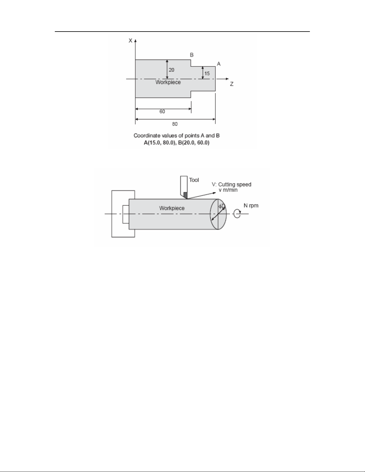
9.1 ABSOLUTE AND INCREMENTAL PROGRAMMING
There are two ways to command travels of the axes; the absolute command, and
the incremental command. In the absolute command, coordinate value of the end point
is programmed; in the incremental command, move distance of the axis itself is
programmed.
For the above figure, incremental command programming results in:
U40.0W_60.0;
While absolute command programming results in:
X70.0 Z40.0;
The absolute/incremental commands are distinguished by address words.
Absolute
command
Incremental
command
Notes
X U
Z W
(Example): X_ W_ ;
Incremental command (Z axis move command)
Absolute command (X axis move command)
NOTE:
For special G code, either absolute command or incremental command is
commanded in G90/G91. And use X/Z for the address.
G90: Absolute command
G91: Incremental command
X axis move
command
Z axis move
Command
Page 55

Ⅱ PROGRAMNING -9(COORDINATE VALUE AND DIMENSION) 9-2
For the above figure, programming is as follows.
Incremental programming
G91 X40.0 Z-60.0;
Absolute programming
G90 X70.0 Z40.0;
(Example):
Command methods Address
Absolute
programming
Incremental
programming
Specifies an end
point in the work
coordinate
Specifies a
distance from start
point to end point
X (Coordinate value
on the X axis)
Z (Coordinate value
on the Z axis)
U (Distance along the
Z (Distance along
the Z axis)
X axis)
Command specifying
Movement from B to A above
X400.0 Z50.0;
U200.0 W-400.0;
NOTE:
1. Absolute and incremental commands can be used together in a block. In the
above example, the following command can be specified:
X400.0 W-400.0;
2. When both X and U or W and Z are used together in a block, the one specified
later is effective.
Page 56

Ⅱ PROGRAMNING -9(COORDINATE VALUE AND DIMENSION) 9-3
9.2 INCH/METRIC CONVERSION (G20, G21)
Either inch or metric input can be selected by G code.
Unit system G Code Least input increment
Inch G20 0.0001inch
Millimeter G21 0.001mm
This G code must be specified in an independent block before setting the
coordinate at the beginning of the program.
The unit systems of the following items can be changed with G codes:
(1) Feedrate commanded by F code
(2) Positional command
(3) Offset value
(4) Unit of scale for manual pulse generator
(5) Movement distance in step feed
(6) Some parameters
NOTE:
1. When the power is turned on, the NC status is the same as that held before
the power was turn off.
2. G20 and G21 must not be switched during a program.
3. When the machine unit and the input unit systems are different, the maximum
error is half of the least command increment. This error is not accumulated.
4. When switching inch input (G20) to metric input (G21) and vice versa, the
offset value must be reset according to the input unit.
9.3 DECIMAL POINT PROGRAMMING /POCKET CALCULATOR
TYPE DECIMAL POINT PROGRAMMING
This control can input numerical values with a decimal point. However, some
addresses cannot use a decimal point. A decimal point may be used with mm, inches
or second values. The location of decimal point is mm, inch or second.
Z15.0 Z15mm or Z15 inch
F10.0 10mm/r,10mm/min,10inch/r,10inch/min
The following addresses can be used with a decimal point:
X, Z, U, W, R, A, K, I, F
NOTE:
1. In the dwell command, decimal point can be used with address X but not
with address P. (This is because P is also used for a sequence number.)
2. The appropriate G code should be specified before the numerical values are
specified in one block.
(1) G20; (inch dimension)
X1.0 G04;
Page 57

Ⅱ PROGRAMNING -9(COORDINATE VALUE AND DIMENSION) 9-4
The value X1.0 is regarded as the distance of motion (in inches),
X10000G04 is assumed resulting in dwelling for 10 seconds.
G04X1.0
This is regarded as G04X1000 and dwell is performed for a second.
(2) G98 (mm/min)
F1. G99; This is regarded as F1 G99, 0.01mm/r (specified G99
mm/r)
G98 (specified mm/min)
G99 F1; Regarded as G99 F100, 1mm/r (specified G99 mm/r)
3. This is great difference in values with and without the decimal point, when
programmed conventional decimal point programming.
G21; (millimeter dimensions)
X1. …… X1 mm
X1 …… X0.001 mm
G20; (Inch dimension)
X1. …… X1 inch
X1 …… X0.0001inch
4. Values with and without a decimal point can be specified together.
X1000Z23.7;
X10.Y22359;
5. Values less than the least input increment are rounded off.
When X1.23456 is specified, X1.234 is assumed in millimeter input and
X1.2345 is assumed in inch input.
6. When a number with a decimal point has been input, the number is converted
into an integer of the least input increment.
Example:
X12.34 → X12340(input in millimeter)
This converted integer is checked for its number of digits.
Example:
X123456.7 → X123456700(input in millimeter)
An alarm occurs because the converted integer exceeds 7 digits.
7. Parameter P013 PODI specified default decimal point or not.
PODI : When the addresses that decimal points can be specified in a
program haven’t decimal point, a decimal point is conformed to exit.
Eg:X100=X100. (X100mm)
8. A decimal point is necessary or not by using parameter P013 PODI, in order
to prevent a decimal point omitting in absolute programming.
POD 0: a decimal point is optional
1: a decimal point is necessary, or an alarm occurs (No.007).
SPECIAL EXAMPLE:
1 Though F100. =F100, when parameter POD=1, a decimal point is necessary.
(F100.)
Page 58

Ⅱ PROGRAMNING -9(COORDINATE VALUE AND DIMENSION) 9-5
2 Address Q can specify with the decimal point, when macro variables DO=1, 1. Or
0.01 must be specified in address Q. If the low eight-bit of macro variables #1132
are 1: G65 H01 #1132 Q0.255
9.4 DIAMETER AND RADIUS PROGRAMMING
Since the work cross sections usually circular in CNC lathe control programming,
its dimension can be specified in to two ways: diameter and radius.。
When the diameter is specified, it is called diameter programming and when the
radius specified, it is called radius programming.
When using diameter programming on the X axis, note the conditions listed in the
following table.
Item Notes
Z axis command
X axis command Specified with a diameter value.
Incremental command with address
U
Coordinate system setting(G50)
X component of tool offset value
Parameters in G90, G92, G94, such
as cutting depth along X axis.
Radius designation in circular
interpolation (R,I,K)
Feedrate along X axis
Display of X-axis position Displayed as diameter value.
Specified independently of diameter or
radius value.
Specified with a diameter value.
In the above figure, specifies from D2 to
D1 for tool path B to A.
Specified an X axis coordinate value with
a diameter.
Parameter setting (NO.004, ORC)
determines either diameter or radius
value.
Specified a radius value.
Specified a radius value.
Change of radius/rev.
Change of radius/min.
Page 59

Ⅱ PROGRAMNING -9(COORDINATE VALUE AND DIMENSION) 9-6
NOTE:
1. In the following explanations, although the type of programming (diameter or
radius) is not specified, X axis graduation indicates diameter value in radius
programming.
2. When a diameter value is specified for the tool offset it indicates that when the
outer diameter is cut with a new tool offset value the outer diameter is
changed by the offset value.
For example, when the offset value changes by 10 mm while the tool remains
unchanged, the outer diameter changes by a diameter value of 10 mm.
3. When using a radius value for the tool offset value, the tool length itself can be
set.
Page 60

Ⅱ PROGRAMMING -10(SPINDLE FUNCTION) 10-1
10. SPINDLE FUCTION(S FUCTION)
10.1 SPINDLE SPEED COMMAND
By specifying a numerical value following address S, a code signal and a strobe
signal are transmitted to the machine tool. This is mainly used to control the spindle
speed. An S code can be commanded in a block.
Refer to the machine tool builder’s manual for the number of digits commandable
with address S and the correspondence between the S Codes and machine operations.
When a move command and an S code are specified in the same block, the two
commands will be execution simultaneous.
10.1.1 S 2-digit command
This spindle speed can be specified by address S followed by 2-digit code.
The NC machine provide eight- level spindle speed function when not choose the
analogue spindle function.
Refer to the appropriate manual provided by the machine tool builder for details
such as the relation between S Code and spindle speed, and how many levels of
spindle speed transmission provided by the machine tool.
S1~S8
S code’s execution time is set by the donors No.209.
Setting value: 0~255 (128ms~32.640ms)
Setting time=setting value x 128ms
Setting time
S code execut ion start
NOTE:
1. When more than S code is specified, an alarm occurs and execution stops.
02:S code error
2. A 2-digit S code is effective, if a 4-digit S code is specified, the last 2-digit is
effective.
3. S code setting time’s parameter (see 12.2)
Execute the next block
10.1.2 S4-digit command
10.1.2.1 Automatic mode
The spindle speed can be specified directly by address S followed by a four-digit
value (rpm). The unit for specifying the spindle speed may vary depending on the
machine tool builder.
Page 61

Ⅱ PROGRAMMING -10(SPINDLE FUNCTION) 10-2
10.1.2.2 Jog mode
When spindle function is selected by users, the bit JOGS of PLC parameter
No.201 can be set to control analog spindle function in jog mode.
1 JOGS=1, S code specifies analogue spindle speed.
2 JOGS=0, Analogue spindle speed is set by the following parameter in JOG
mode.
P61:Power-on initial value of analogue spindle speed in JOG mode.
unit:Rpm
P62:incremental value or decrement of analogue spindle speed.
P60 is upper limit in increment.
Spindle rotates at the speed to be set by parameter after spindle start-up in Jog
mode. When pressing the spindle override key + or -, each incremental value or
decrement of spindle speed is the increment set by parameter P62. Manual spindle
rotational speed is displayed on the address SRPM of PROGM screen in JOG mode.
In other mode, spindle rotates at the speed specified by S code.
NOTE:
1. Rotational speed specified by parameter is not spindle motor rotational speed
but spindle speed. Spindle analogue voltage is determined by spindle shift inside CNC.
2. If mode shifts between manual and non- manual, spindle speed will change
during rotation.
3. Standard parameter setting: P061=100 P062=50
4. JOG mode includes jog feed, handle/step or zero return modes (machine or
program zero return).
10.2 SIMULATING SPINDLE GEAR SHIFTING
10.2.1 Auto/manual spindle gearing shifting during automatic
program run
⊙Program code: M41~M44
M41 : Gear 1, max. speed is set in parameter no. P57.
M42 : Gear 2, max. speed is set in parameter no. P58.
M43 : Gear 3, max. speed is set in parameter no. P59.
M44 : Gear 4, max. speed is set in parameter no. P60.
⊙Relative parameters
Diagnosis 199
AGER=1 : Simulating automatic spindle gear shifting. 0: Simulating manual
spindle gear shifting.
AGIN=1: it’s necessary to check the in-position signal when shifting gear.
AGIM :Selecting active level for gear signal (0: low level, 1: high level).
AGER AGIN AGIM
Page 62

Ⅱ PROGRAMMING -10(SPINDLE FUNCTION) 10-3
Diagnosis 193
Time for shifting gear 1
Shifting time 1 Time unit: 256ms. Setting range 0~65s (8-bit binary).
Diagnosis 194
Time for shifting gear 2
Shifting time 2 Time unit: 256ms. Setting range 0~65s (8-bit binary).
Diagnosis 202
AGST
AGST 1: When simulating spindle gear shifting by program code way, gear
shifting is done manually (i.e. shifting can be done only by pressing 〖Cycle Start〗
after entering the in-position gear signal).
Note: above parameters can be modified only when both the parameter and
program switches are on.
(1) Input/Output interface
Diagnosis 001
M41I M43I M44I
Diagnosis 002
M42I
M41I-M44I:Input signal: gear in-position signal.
Diagnosis 050
M44 M43 M42 M41
M41-M44:Output signal: gear output signal.
(2) Automatic gear-shifting procedure
The procedure is as follows when the program is running M41~M44 code
automatically:
① Check whether the system has function of spindle simulation, and whether
AGER of diagnosis parameter 199 is 1. Otherwise, it creates alarm “01: M
code error”.
② Check whether the gear of command code is same with the gear output
currently. If yes, M code ends, no gear shifting will be done. If not, gear
shifting will be done.③
③ Make spindle speed the value set by P021. If any axis has motion, dwell
that.
④ After delay a time set by diagnosis parameter 193 (gear-shifting time 1),
turn off the output signal from original gear, and output the signal of new
gear.
⑤ When AGIN=1 for diagnosis parameter 199, go to , otherwise .⑥⑦
⑥ Check input signal of gear in-position signal (its level will be selected by
AGIM of diagnosis parameter 199), if yes, go to .⑦
Page 63

Ⅱ PROGRAMMING -10(SPINDLE FUNCTION) 10-4
⑦ After delay a time set by diagnosis parameter 194 (gear-shifting time 2), if
AGST=0 for diagnosis parameter 202, go to .⑨
⑧ Wait for 〖Cycle Start〗, press it and execute .⑨
⑨ Simulate spindle speed in output of new gear, the gear-shifting M code
ends.
10.2.2 Manual spindle gear shifting
When AGER=0 for diagnosis parameter199, it is to simulate manual spindle gear
shifting. It is to determine the spindle gears depending upon the input interface.
Input interface:
Diagnosis 001
Diagnosis 002
M42I
M43I M44I
Input signal M44I=1, the system outputs the highest spindle speed set by
parameter P60 (4th gear).
Input signal M43I=1, the system outputs the highest spindle speed set by
rd
parameter P59 (3
gear).
Input signal M42I=1, the system outputs the highest spindle speed set by
nd
parameter P58 (2
gear).
When input signals M42I~M44I are all 0, the system outputs the highest spindle
speed set by parameter P57 (1st gear).
10.3 CONSTANT SURFACE SPEED CONTROL(G96,G97)
If surface speed (relative speed between tool and workpiece) is set after address S,
the spindle speed is calculated so that the surface speed is always the specified value
in correspondence with the tool position. Voltage is fed to the spindle control section so
that the spindle rotates to produce the correct surface speed.
The units of surface speed are as follows:
Input unit Surface speed
unit
mm m/min.
inches feet/min
The surface speed unit varies with machine tool builder.
The following G codes are used for surface speed control:
G96 S__;
The figure following S specifying surface speed (m/min or feet/min).
Constant surface speed control is cancelled by the following command:
Page 64

Ⅱ PROGRAMMING -10(SPINDLE FUNCTION) 10-5
G97 S__;
The figure following S specifying spindle speed (rpm).
When constant surface speed control is used the work coordinate system must be
set so that the center of rotation meet the Z-axis (X=0).
X
Z
(n
3000
2800
2600
2400
2200
2000
1800
1600
1400
1200
1000
800
600
400
0
0
20
5
0
60
1
The spindle speed(rpm)
coincides with the surface
speed(m/min) at approx.
160mm(radius)
S
为
6
0
4
0
0
3
0
0
2
0
0
0
0
100
m
0
min
140 180 220 260 300
Unit(mm)
10.3.2 Spindle speed override
An override for specified surface speed or spindle speed can be applied by issuing
a signal from the machine tool in 50,60,70,80,90,100,110, or 120.
10.3.3 Clamping maximum spindle speed(G50)
Page 65

Ⅱ PROGRAMMING -10(SPINDLE FUNCTION) 10-6
The figure following G50S specifies the maximum spindle speed for constant
surface speed control in rpm.
G50 S__;
When the spindle speed in constant surface speed control reaches the value
specified in the above program, the speed is clamped at this maximum value.
10.3.4 Rapid traverse (G00) inconstant surface speed constant
control
In a rapid traverse block including a G00 command, the surface speed is not
calculated command, the surface speed is not calculated according to the change in
tool position, but on the basis of the end position of the block because there is no
cutting during the rapid traverse.
NOTE:
1. When the power supply is turned on, the maximum spindle speed is not set that
is, the speed is not clamed.
2. If the maximum spindle speed is set by a G92 command, clamping only effective
for G96 but is not effective for G97.
3. G50 S0 ; indicates that the spindle speed is clamped at 0 rm.
4. The value for S specified in G96 mode is not affected by G97 and is restored
when returning to G96 mode.
G96 S50 ; (50m/min.or 50 feet/min)
G97 S1000; (1000 rpm)
G96 X3000; (50 m/min. or 50 feet/min)
5. Even when a machine is not operating in machine lock status, the constant
surface speed is calculated according to the change in the coordinate value of the Xaxis in the program.
6. Constant surface speed control is effective in thread cutting mode. Therefore, it
is better to cancel constant surface speed control with G97 for face thread cutting or
taper thread cutting so that the CNC unit and servo system can adapt easily to the
change in spindle speed.\
7. Although meaningless, G96(constant surface speed control) and G98 (feed per
minute) can be in effect at the same time.
8. When switching from G96 to G97 mode, the last spindle speed specified in the
G96 command is used for the S value in the G97 mode if S (rpm) is not specified in
the G97 block.
N100 G97 S800; (800 rpm)
...
N200 G96 S100; (100 m/min)
...
...
Page 66

Ⅱ PROGRAMMING -10(SPINDLE FUNCTION) 10-7
N300 G97; (X rpm)
X is the spindle speed (X rpm) in the block before N300. In other words, when
the G96 mode changes to the G97 mode, the spindle speed does not change without S
command in G97. When switching from G97 to G96, the value of S in the previous
G96 mode is effective ,so if has not been specified, S=0 m/min.(feed/min).
9. The surface speed specified by constant surface speed mean the speed to the
programmed path; not to the position where offset value is added to the programmed
path.
Example:
(Diameter designation)
N8 G00 X1000.Z1400.;
N9 T0303;
N11 X400.Z1050.;
N12 G50 S3000; (Designation of max. spindle speed)
N13 G96 S200; (surface speed 200 m/min)
N14 G01 Z700. F1000;
N15 X600. Z400.;
Page 67

Ⅱ PROGRAMMING -10(SPINDLE FUNCTION) 10-8
N16 Z....;
The CNC calculates the spindle speed which is proportional to the specified
surface speed at the position of the programmed coordinate value on the X axis. This is
not the value calculated according to X axis coordinate after offset when offset is valid.
At the end point N15 in the example above, the speed at 600 diameter.(Which is not
the turret center but the tool nose) is 200 m/min. If X axis coordinate value is negative,
the CNC uses the absolute value.
10.4. CONTROLLING SPINDLE CHUCK
10.4.1 Manual chuck control – input signal QP
When the foot switches for controlling chuck acts, the time sequence for chuck
controlling is as follows:
QP(Diag. 01.7)
QPJ(Diag. 49.2)
QPS(Diag. 49.3)
10.4.2 Automatic chuck control – program code M10/M11
M10:outputs chuck clamp signal.
M11:outputs chuck unclamp signal.
10.4.3 Checking chuck feedback signal
When QPIN of diagnosis parameter 202 is set to be 1, to start the spindle, it is
also necessary to check chuck clamp feedback signal in addition to check chuck clamp
signal. If the chuck clamp is not in place, it’s impossible to start the spindle, and it will
generate no.015 alarm.
10.4.4 Setting chuck outputting way
(1) If QPLS=0 for diagnosis parameter 199, the chuck output signal QPS/QPJ is in
level way (refer to the time sequence above).
(2) If QPLS=1 for diagnosis parameter 199, the chuck output signal QPS/QPJ is in
pulse way, the width of the pulse signal is set by diagnosis parameter 192 (8-bit binary).
Time unit: 128ms.
10.5 CONTROLLING TAILSTOCK
10.5.1 Manual tailstock control – input signal TW
When the foot switch for controlling tailstock acts, the time sequence for tailstock
controlling is as follows:
Page 68

Ⅱ PROGRAMMING -10(SPINDLE FUNCTION) 10-9
TW(Diag. 02.7)
TWJ(Diag. 49.4)
TWS(Diag. 49.5)
10.5.2 Automatic tailstock control – program code M78/M79
M78: outputs tailstock forward signal.
M79: outputs tailstock retract signal.
10.5.3 Setting tailstock outputting way
(1) If TPLS=0 for diagnosis parameter 202, the tailstock output signal TWJ/TWT is
in level way (refer to the time sequence above).
(2) If TPLS=1 for diagnosis parameter 202, the chuck output signal TWJ/TWT is
in pulse way, the width of the pulse signal is set by diagnosis parameter 191 (8-bit
binary). Time unit: 128ms.
The no. of tools can be provided by the system will be set by PLC parameter
diagnosis 212, and the max. is 12.
10.6 SPINDLE ROTATION DWELL FUNCTION
When standard KND additional operator panel is used, the following switches are
added.
This knob is used for pausing axis feeding and spindle rotation. The
knob has three places: Left, Mid. and Right
• When the knob is at left, it is under normal operation.
• When the knob is at middle, the axis movement is paused.
• When the knob is at right, both the axis movement and the spindle are
paused.
When the knob is turned from right to the middle, the spindle will recover
its former state, and if it is turned to the left further, you must press again
Cycle Start button.
Page 69

Ⅱ PROGRAMMING -11( TOOL FUNCTION) 11-1
11. TOOL FUNCTION (T FUNCTION)
By specifying a 2-digit numerical value following added T, a BCD code signal
and a strobe signal are transmitted to the machine tool. This is mainly used to select
tools on the machine. One T code can be commanded in a block. When a move
command and a T code are specified in the same block, the two commands will
execution simultaneous.
Refer to the machine tool builder’s manual for the number of digits commandable
with address T and the correspondence between the T codes and machine operations.
The value after the T code indicates the desired tool. Part of the values is also
used as the offset number indicating the compensation amount for tool offset. The
following two kinds of specifications can be selected
T
○○ ○○
Tool offset number
Tool selection
11.1 Tool-changing Procedure
The max. time needed for changing tool is set in diagnosis parameter 206 (low
byte) and 207 (high byte), the setting range is 0~65535 (16-bit binary). Time unit:
16ms. If the tool-changing time exceeds the set value, 05 alarm occurs: too long tool
changing time.
When Tb≥D211, 11# alarm occurs: antilock time is too long when changing tool.
When executing T code, first output tool carrier CW rotation signal (TL+) to rotate
the tool carrier, after receiving in-position signal for the tool specified by T code, CW
rotation signal for the tool carrier is off. After a delay of T1, the tool carrier rotates CCW
Page 70

Ⅱ PROGRAMMING -11( TOOL FUNCTION) 11-2
and locks (TL-), and it checks the lock signal *TCP. After receiving this signal, it delays
time set by diagnosis no. D213, turns off tool carrier CCW rotation signal (TL-), the tool
change ends, and the program goes to the next block. If the tool no. under execution is
consistent with the current tool no. (registered automatically in diagnosis no. D203 of
PLC parameter), the tool-changing command ends immediately, and goes to the next
block.
After the system outputs tool carrier CCW signal, if the system fails to receive *TCP
signal in time set by diagnosis D211, the system will alarm and turn off tool carrier
CCW signal.
NOTE:
Current tool no. is saved in diagnosis D203. When tool changing ends normally,
the system will automatically modify this value. At lower right corner of the screen, T
indicates the T code and tool offset no. of current command. At power on, T code sets
D203 as initial value. At normal tool changing, these two values are same. After
commanding T code, these two values are not same because the original tool carrier is
not in position due to some reason, T indicates the commanded tool no., while D203
maintains tool no. before tool changing. When the commanded tool no. is same with
D203, the system will not change tool. Therefore when current tool no. is not same with
D203, generally it is necessary to set D203 as current tool no. When changing tool
manually, only after tool change ends, T code and D203 will be modified into new value.
11.2 FUNCTION FOR CHECKING INPUT SIGNAL OF TOOL
CARRIER
When bit CKDTI of PLC (diagnosis) parameter D201 is set as 1, it will check the
input signal of tool carrier. And it will carry out the following functions:
z Check again tool carrier signal after changing a tool. If the signal is correct,
the tool change will finish. Otherwise, it will alarm, and the program will pause.
(generates Pause signal)
z Check periodically whether tool carrier signal matches with that recorded in
the system.
z Checking contents:
z 1. Whether access should be connected
z 2. Whether access should not be connected. For both cases it will generate
alarm “08: wrong total No. of tool positions or tool input signal.”
NOTE:
1. Check the No. of input signals based on the tool No. set by PLC
parameter D212.
Page 71

Ⅱ PROGRAMMING -11( TOOL FUNCTION) 11-3
2. If it is not necessary to check or gang tool is used, set CKTDI=0.
11.3 SELECTING REAR TOOL CARRIER
It is rear tool carrier when bit RVX is 1 for PLC parameter 201. In this case the
former manual X axis +, - movement will become reverse. Meanwhile the indicator
lamps on corresponding keys will light up.
11.4 PARAMETERS RELATIVE WITH TOOL CHANGING
(1) System parameters
Tool carrier in-position signal (T12~T01) Bit 1 TSGN of parameter P011 sets
high or low active level.
TSGN 0 : Tool carrier in-position signal high level is active (Normally open)
1 : Tool carrier in-position signal low level is active (Normally close)
Tool carrier lock signal (*TCP) Bit0 TCPS of parameter P011 sets high or low
active level.
TCPS 0 : Tool carrier lock signal low level is active (Normally close)
1 : Tool carrier lock signal high level is active (Normally open)
NOTE:
1. Generally high level is selected as active signal when external signal is
connected. Otherwise when the signal line is off, it will regard that as active
immediately.
2. When there is no tool carrier lock signal, it can go without connecting the
signal, and set parameter TCPS with low level as active, and set CCW
rotation lock time by setting time D213.
(2) PLC parameter
T1 : Delay time from end of tool carrier CW rotation to start of CCW rotation.
Diagnosis No. 210, set value 0~255 (0~4080 ms) Unit: 16ms.
Tool No.: Select tool No. from tool carrier.
Diagnosis No. 212, set value 0~12 unit: piece.
T2 : Delay after receiving CCW rotation lock signal for tool carrier.
Diagnosis No. 213, set value 0~255 (0~4080 ms) Unit: 16ms.
Tool position: Max. time needed for tool changing.
Diagnosis No. 206 (low byte), No. 207 (high byte), set value 0~65535
(0~1048s)Unit: 16ms.
T lock: Max. time signal after receiving CCW rotation lock signal for tool carrier.
Diagnosis No. 211, set value 0~255 (0~16320 ms) Unit: 64 ms.
T present tool No.: Current tool No.
Page 72

Ⅱ PROGRAMMING -11( TOOL FUNCTION) 11-4
Diagnosis No.203. This value is set by system automatically. It is
necessary to set according to current tool no. position for the first use
or after clearing the memory.
(3) Alarm info:
1) 03: error T code.
This alarm occurs, and the tool change & machining program stops when tool
no. specified by T code > max. tool no. set by No.212.
2) 04: wrong setting for tool-changing time.
This alarm occurs, and the tool change & machining program stops when Ta >
T all tool positions.
3) 05: Too long tool-changing time.
This alarm occurs, and the tool change & machining program stops if it fails to
receive the arrival signal of specified tool position after tool carrier starts CW rotation
for the time set by diagnosis No. 206 (low byte) and No. 207 (high byte).
Above tool changing procedure is also suitable for manual tool changing.
The flag position for tool changing can be seen by diagnosis No. 144.
As for the corresponding relationship between commanded tool No. in program
and actual tool, please refer to the operation instructions issued by the machine tool
builder.
4) 11: Too long antilock time at tool changing.
Page 73

Ⅱ PROGRAMMING -12(MISCELLANEOUS FUNCTION) 12-1
12. MISCELLANEOUS FUNCTION
When a move command and an M code are specified in the same block, the two
commands will be executed simultaneous.
(Example)
N1 G01 X50.0 Z-50.0 M05 ;(Spindle stop)
12.1 MISCELLANEOUS FUNCTION (M FUNCTION)
When a 2-digit numeral is specified following address M, a BCD 2-digit code signal
and a strobe signal are transmitted. These signals are used for ON/OFF controls of a
machine function. Normally only one M code is valid for a block.
Then following M codes indicate special meaning.
M03 :spindle CCW
M04 :spindle CW
M05 :spindle stop
M08 :coolant open
M09 :coolant close
M10 :chuck tight
M11 :chuck open
M32 :lubricant open
M33 :lubricant close
M00 :Program stop. Thee cycle operation can be restarted by actuating the CNC.
M01 :Optional stop. This code is only effective when the Optional Stop switch on
the machine control panel has been pressed.
M30 :End of program. The NC tape is turned to the beginning of the program.
M98 :Call of subprogram.
M99 :End of subprogram.
The execution time of other M codes except M00, M30 can be set by diagnose
No.208.
setting value:0~255 (128ms~32.640ms)
setting time = setting value×128 ms。
Page 74

Ⅱ PROGRAMMING -12(MISCELLANEOUS FUNCTION) 12-2
M code execute
Setting time
Next block
Spindle CW/CCW rotation, spindle stop, spindle braking time sequence and setting
time:
CW/CCW
STOP
Interlock
Spindle stop
Spindle brake
T1
T2
T3
T1: When the spindle is rotating, after giving Spindle Stop (Auto or manual) command,
first it enables axis interlock signal, after time delay T1, it gives Spindle Stop signal.
This is set in diagnosis no. 214.
T2: Delay from issuing Spindle Stop signal to giving Spindle Brake signal. It is set in
diagnosis no. 215/216.
T3: Spindle braking time. It is set in diagnosis no. 217/218.
NOTE:
1. When M codes other than above have been specified in the program, the system
will generate the following alarm and stop execution.
2. After M, S, T starts, it still holds even if the mode has changed, and it is impossible
to turn off even by keys in manual way, and you can turn off that by ‘RESET’ (set it
to be active or not by parameter).
3. The M code output is pulse or level, which can be selected by parameter. Refer to
Connection section.
The following M codes have specified special meanings.
1. M30 (Program ends)
(1) Means main program ends.
(2) Stops automatic run and goes under Reset state.
(3) Returns to the start of main program.
Page 75

Ⅱ PROGRAMMING -12(MISCELLANEOUS FUNCTION) 12-3
(4) Adds 1 to the machined pieces.
2. M00: Program stops
Automatic run stops after executing M00 block. Same with single block stop, it
saves all modal info before it. Auto running starts after CNC starts.
3. M98/M99 (call subprogram/subprogram returns)
It is for calling subprogram. For details, refer to the section of Subprogram Control
(II12).
Note:
1. Even if there is a block next to M00, M01 and M30, it is impossible to save in buffer.
2. The code signal will not be sent out when executing M98 and M99.
12.2 USER INTERFACE GO TO FUNCTION M CODE: M91/M92,
M93/M94
When the system runs these M codes automatically, it will carry out program GO
TO functions according to the state of signal for input interface.
12.2.1 Input interface
Diagnosis no. 000
M93I
M91I
12.2.2 Program format
M9* Pn; (*:1~4;Pn: specified block)
When the condition is true, it goes to the block starts with N specified by Pn. If no
n is detected, it generates no. 128 alarm.
12.2.3 Description
M91 :When input signal M91I=0, GO TO. When input signal M91I=1, execute
next block in sequence.
M92 :When input signal M91I=1, GO TO. When input signal M91I=0, execute
next block in sequence.
M93 :When input signal M93I=0, GO TO. When input signal M93I=1, execute
next block in sequence.
M94 :When input signal M93I=1, GO TO. When input signal M93I=0, execute
next block in sequence.
Ex:
N50 M92 P100;
N60 G00 X100. Z100.;
N70 ...;
N100 G00 X0. Z0.;
When executing N50, if the input interface M91I=1, go to N100; if input interface
M91I=0, execute N60 in sequence.
Page 76

Ⅱ PROGRAMMING -12(MISCELLANEOUS FUNCTION) 12-4
12.3 SPECIAL M CODE: M21/M22, M23/M24
These M codes can be used as general M codes, or for setting the execution time
width, or ending program block after waiting the arrival of the input signal.
12.3.1 Relative parameters and I/O interface signal
DGN 199
SM21 1:The output interface has output when executing code M21. 0:The output
interface has no output when executing code M21.
SM23 1:The output interface has output when executing code M23. 0:The output
interface has no output when executing code M23.
DGN 000
DGN 050
SM23 SM21
M23I M21I
M23O M21O
12.3.2 Description on use
M21 :Same with general M code. If parameter SM21 is set as 1, the
output interface M21O has output.
M21 P__ : This block ends after the time specified by P_ elapses. If
parameter SM21 is set as 1, the output interface M21O has output. Output interface
M230 is off at end.
M21 Q__ :Detect input signal M211, if M21I=0, it waits. If M21I=1, ends the
block. In this case, if parameter SM21 is set as 1, the output interface M21O has output.
M22 :Same with general M code. If parameter SM21 is set as 1, the
output of M21O turns off.
As for the using way of M23/M24, refer to above description.
Note 1: M21 and M23 output are off at emergency stop. When Q is specified, it is of
any value.
Note 2: when parameter RSJG=0, press RESET to turn off M21, M23 output,
otherwise don’t turn off that.
12.4 PARAMETERS OF MISCELLANEOUS FUNCTIONS
Page 77

Ⅱ PROGRAMMING -12(MISCELLANEOUS FUNCTION) 12-5
Diagnosis no. 160~222 are battery-holding parameters, a user can set that
depending upon actualities. The set code is binary. As for the corresponding table
between binary and decimal code, refer to appendix 4.
Setting: turn on Program Protect switch, select Diagnosis screen under Input mode,
move cursor to the S/N to set, type in binary data, and press 〖INPUT〗 key.
Way to move cursor:
(1) By Page and arrow keys.
(2) By searching way: P→diagnosis no. to be searched→ key 〖INPUT〗.
№160,161:auto lubricant opentime。(161-high bit,the highest bit can not be
set to 1)
settting unit:s
settting code :0~32767
settting value :〔№161×256+№160〕×1s
setting field:0~32767 s
№162,163:auto lubricant close time。(163-high bit,the highest bit can not be
set to 1)
settting unit:s
settting code :0~32767
settting value :〔№163×256+№162〕×1s
setting field:0~32767 s
№164,165:workpiece number settting value。(165-high bit,the highest bit
can not be set to 1)
settting unit:个
settting code :0~32767
settting value :〔№165×256+№164〕×1 piece
setting field:0~32767 piece
№191: pulse width of tail rest output
settting unit:128 ms
settting code :0~255
settting value :(№191+1)×128 ms
setting field:128ms~32.768 s
№192: pulse width of chuck output。
settting unit:128 ms
settting code :0~255
settting value :(№192+1)×128 ms
setting field:128ms~32.768 s
№193/194: half of spindle shifting gear time
settting unit:256 ms
settting code :0~255
Page 78

Ⅱ PROGRAMMING -12(MISCELLANEOUS FUNCTION) 12-6
settting value :(№193+1)×256 ms
setting field:256ms~65.536s
№206,207:the longest time of tool change 。
settting unit:16 ms
settting code :0~65535
settting value :[№207×256+№206]×16 ms
setting field:0~1048.560 s
№208: M code process time 。
settting unit:128 ms
settting code :0~255
settting value :(№208+1)×128 ms
setting field:128~32.768 s
№209: S code process time
settting unit:128 ms
settting code :0~255
settting value :(№209+1)×128 ms
setting field:128~32.768 s
№210: Delay time T1 from spindle stop command sending to spindle stop signal
sending。
settting unit:16 ms
settting code :0~255
settting value :(
№210+1)×16 ms
setting field:16~4.096 s
№211: the longest time of tool CW rotation tight T2
settting unit:64 ms
settting code :0~255
settting value :(№211+1)×64 ms
setting field:64~16.32 s
№212: tool number。
settting unit:1
settting code :1~8
№213: delay time from receiving *TCP signal to tool CW tight signal close.
settting unit:16 ms
settting code :0~255
settting value :(№211+1)×16 ms
setting field:16~4.096 s
№214: delay time T1 from spindle stop command to spindle stop signal
settting unit:16 ms
settting code :0~255
Page 79

Ⅱ PROGRAMMING -12(MISCELLANEOUS FUNCTION) 12-7
settting value :№214×16 ms
setting field:0~4.096 s
№215,216:delay time from spindle stop signal to spindle brake signal
settting unit:16 ms
settting code :0~65535
settting value :(№216×256+№215)×16 ms
setting field:0~1048.560 s
№217,218:spindle brake time。
settting unit:16 ms
settting code :0~65535
settting value :〔№218×256+№217)×16 ms
setting field:0~1048.560 s
№219: External buzzer output signal sending time。
settting unit:32 ms
settting code :0~255
settting value :№219×32 ms
setting field:0~8.192 s
№220,221:pressure protect signal delay time after power on
settting unit:16 ms
settting code :0~
settting value :〔№216×256+№215)×16 ms
setting field:0~1048.560 s
№222: valid time width of pressure protect signal.
settting unit:16 ms
settting code :0~255
settting value :№214×16 ms
setting field:0~4.096 s
65535
The alarm related to auxiliary functions can display by external information
screen. An alarm occurs, the external information screen will display automatically, on
top of it the alarm details will display, and “ALARM” will flash at the end of the screen.
01:M codes error.
Illegal M codes are specified in program.
02:S codes error.
Illegal S codes are specified in program.
03:T codes error.
Page 80

Ⅱ PROGRAMMING -12(MISCELLANEOUS FUNCTION) 12-8
Illegal T codes are specified in program.
04:Tool exchange time error.
When Ta is more than T, alarm occur and stop tool movement and program.
05:Tool exchange time too long.
The specified tool reach signal dose not receive via time tool Ta after tool
CCW rotation, the alarm will stop tool movement and program.
06:M03,M04 code error.
Spindle is specified rotary CW/CCW without spindle stop while it is rotating.
07:S code is specified as spindle rotating
S code for gear shift is specified while spindle is rotating.
08:The whole tools parameter setting error.
09:Pressing “cycle start” key after gear shift in jog mode.
(parameter P012 BIT5 SMANL=1)
10: Protect door don’t close after cycle start.
11: Tool CW tight time too long
14: Pressure shortage
15: Spindle rotate as chuck open
Page 81

Ⅱ PROGRAMMING -13(PROGRAMCONFIGURATION) 13-1
13. PROGRAM CONFIGURATION
13.1 PROGRAMR
A program is composed of many Program Sections, and a program section
consists of several blocks. A program section starts with a program number and ends
with a program end code.
13.1.1 Main program and subprogram
(1) Main program
A program is divided into a main program a main program and subprogram:
Normally, the `CNC operates according to the main program, but when a command
calling a subprogram is encountered in the main program, control is passed to the
subprogram. When a command indicating to return to the main program is encountered
in the subprogram, control is return to the main program.
Main program
subprogram
Instruction 1
Instruction 2
...
...
...
Follow the direction of
the subprogram
Instruction N
...
...
...
A total of 128 main programs and subprograms may be stored in the CNC memory,
and the CNC uses one of these main programs to move the CNC machine tool.
Refer to Ⅲ 9.2 for how to register programs.
(2) Subprograms
When a program contains certain fixed sequences of frequently repeated patterns,
these sequences or patterns may be entered into memory as a subprogram to simplify
programming. The subprogram can be called in AUTO mode. A subprogram can call
another subprogram. When the main program calls a subprogram, it is regarded as a
one loop subprogram call. Thus, two loop subprogram calls can be executed as shown
below.
Instruction 1
Instruction 2
...
...
...
Return to main
program
Page 82

Ⅱ PROGRAMMING -13(PROGRAMCONFIGURATION) 13-2
However, four loop subprogram calls can be executed using custom macro. A call
command can call a subprogram repeatedly. A call command can specify up to 999
repetitions of a subprogram.
(A) Preparation of subprogram
A subprogram is prepared in the following format:
At the top of subprogram, a subprogram No. identifying the subprogram is
specified after “O”. Specify M99 at the end of a subprogram. Subprogram end
command “M99” need not be specified in a block by itself.
(Example) X……M99 ;
Please refer to Chapter Ⅲ-9 about the methods of saving subprograms
Note:
For compatibility of the CNC tape with other devices, N0000 is also used as a
subprogram No. instead of O (:). A sequence number under N is registered as a
subprogram number.
(B) Subprogram execution
A subprogram is executed when called by the main program or another
subprogram. A subprogram call has the following format:
Page 83

Ⅱ PROGRAMMING -13(PROGRAMCONFIGURATION) 13-3
When the repetition times are omitted, the subprogram is repeated once.
(Example) M98 P51002;
This command specifies “Call the subprogram (subprogram number 1002) five
times.”
(Example) X1000 M98 P1200;
In this example, the subprogram (subprogram number 1200) is called after
completing movement in the X-axis direction.
(Example) The execution sequence of a main program which calls a subprogram is
as follows:
When the subprogram is called by another subprogram, it is executed in the same
sequence as shown in the above example.
NOTE:
1. If the subprogram number specified by address P can not be found, an
alarm (PS078) is displayed.
2. The subprogram call command M98 PXXXX cannot be input from the MDI.
(C) Notes on subprogram control
The following special specifications can be used to control subprogram execution.
(1) When a sequence number is specified in address P of the last block of a
subprogram, control dose not return to the block after the block in which the
subprogram was called`, but rather to the block with the sequence number specified in
address P. However, this is only effective in memory operation. The processing time for
return to the specified block is considerably longer than that for normal return.
Page 84

Ⅱ PROGRAMMING -13(PROGRAMCONFIGURATION) 13-4
(2) If the M99 command is executed in the main program, control returns to the
start of the main program. For example, a /M99 block is inserted in the proper position
of the main program and `the optional block skip is off, M99 is executed, and control
returns to the start of the main program and the program is executed again. If the
optional block skip is turned on, /M99 is omitted and control is passed to the next block.
If /M99Pn has been inserted, control does not return to the start, but returns to the
block whose sequence number is “n”. The processing time for return to sequence
number n is longer than return to start.
13.1.2 Program number
This control can store program in its memory. A 4-digit program number following
address O is used to differentiate one program from another.
O □□□□
Program (1~9999,Leading zero suppression)
Address O
Programs start with a program number, and end with M02 or M30。
13.1.3 Sequence number and block
A program is composed of several commands. One command is called a block.
One block is separated from another block with an end of block code. This manual
uses “;” as the end of block code.
A 4-digit sequence number can be specified (1-9999) following address N at the
head of a block. The leading zero can be suppressed.
The order of sequence numbers is arbitrary and need not consecutive. Sequence
numbers can be specified in all blocks or only in blocks requiring them. It is
Page 85

Ⅱ PROGRAMMING -13(PROGRAMCONFIGURATION) 13-5
A
recommended that sequence numbers be specified sequentially at important points
such as when a tool is changed and a new tool is used.
Note: Because program number 0 is invalid, a sequence number regarded as a
program number must not be 0.
13.1.4 Optional block skip
When a slash followed by a number (/n) is specified at the beginning of a block
and the optional block skip switch n on the machine operator panel is set ON, the block
with /n corresponding to switch number the n is ignored in the tape or memory
operation. When the optional block skip switch n is set OFF, the block with /n is valid.
Therefore, operator can skip a block with /n at his; discretion. 1 in/1 may be omitted.
The following range is ignored when the optional block skip switch in ON:
/N123 G01 X4……; N7890
│← Range ignored →|
(Example)
N100 X100.0 ;
/N101 Z100.0 ;
N102 X200 ;
In the above example, the blocks of N101 are skipped when switch No. is ON.
Note:
1. A slash (/) must be specified at the start of a block. If it is placed elsewhere in
the block, the information from the slash (/) to the EOB code is ignored, while
information before the slash (/) is effective.
2. The optional block skip is identified when the information is read into the buffer
storage from the tape or memory. When a block preceded by a slash has been read
into the buffer, it is not ignored even if the OPTIONAL BLOCK SKIP switch is turned on.
3. This function is also effective during a sequence number search.
4. When storing the program in memory, this function is ineffective. A block with a
slash (/) is also stored in the memory regardless of the position of the OPTIONAL
BLOCK SKOIP switch.
5. When punching out the program from memory, the program is punched out
regardless of the position of the OPTIONAL BLOCK SKIP switch.
13.1.5 Word and address
A block is composed of one or more words. A word is composed of an address
followed by a number as is shown below. (An algebraic sign +/- may be added before
the numerical value.)
X
1000
ddress Numerical value
Page 86

Ⅱ PROGRAMMING -13(PROGRAMCONFIGURATION) 13-6
The address is a letter which indicates the meaning of the numerical value
following the address. Addresses and their meanings are shown below.
Some addresses may vary in meaning depending on preparatory functions specified in
the program.
Function Address Meaning
Program number O Program number
Sequence number N Sequence number
Preparatory G Motion mode(linear,arc,etc)
X,Z,U,W Coordinate axis motion
command
Dimension word
Feed function F Federate, thread lead
Spindle speed function S Spindle speed
Tool function T Tool number, tool offset number
Miscellaneous function
Dwell
Program number designation
Repetitive P Repetitive count in subprogram
Sequence number designation
R Arc radius, corner r
I,K Coordinate values of arc center,
chamfering
M ON/OFF control on the machine
tool
P,U,X
P Designation of the subprogram
P,Q,R
Dwell time
number
Designation of sequence
number of repetitive in program
13.1.6 Basic addresses and command value range
The basic addresses and command value range are listed in the table below. Note
that these figures give the maximum numerical limit, not the mechanical limit of the
CNC machine tool. Under CNC control, the tool may traverse up to 10m (in millimeter
input) along the X axis, but actually traveling distance may be limited to 2m for the
specific machine tool. Similarly, CNC control may permit a maximum cutting feed of 25
Page 87

Ⅱ PROGRAMMING -13(PROGRAMCONFIGURATION) 13-7
m/min, but the CNC machine tool may be limited to 3 m/min. The manual issued by the
machine tool manufacturer should be closely consulted, in addition to this manual when
programming to ensure that the actual limitations of the specific machine tool are not
exceeded.
Basic Addresses and Command Value Range
Function Address Input in mm Input in inch
Program number O
Sequence number N
Preparatory function G
Dimension word
Feed per minute F
Feed per revolution F
Spindle speed function S
Tool functions T
Miscellaneous functions M
Dwell X,U,P
Designation of
sequence number,
number of repetition
Designation of
sequence number
X,Z,U,W,I,K,A,
P,Q 1~9999 1~9999
R
P
1~9999 1~9999
1~9999 1~9999
0~99 0~99
±99999.999mm ±9999.999 inch
1~15000 mm/min
0.0001~500.0000
mm/rev
0~9999 0~9999
0~1232 0~1232
0~99 0~99
0~99999.999sec 0~99999.999 sec
1~9999 1~9999
0.01~600.00
inch/min
0.000001~
9.999999
inch/min
13.2 PROGRAM END
The end of program is indicated by punching the following code at the end of
program section.
ISO Meaning
M30 LF Program End and Rewind
M99 LF Subprogram End
When the End of Program is sensed during the execution of a program, the CNC
terminates the execution of the program and enters a reset state. In case of M30 LF,
Page 88

Ⅱ PROGRAMMING -13(PROGRAMCONFIGURATION) 13-8
the program is returned to its beginning (in Memory mode). When the subprogram end
code is sensed in a subprogram, control is returned to the program which called the
subprogram.
13.3 TABE END
The end of a tape is indicated by punching the code below immediately following
the program end of the last program on a tape.
ISO Meaning
% Tape End
NOTE:
If M30 is not at the end of the program section, and % is about to be excuted,
the CNC enters the reset state.
Page 89

Ⅱ program —14(functions to simplify programming) 14 - 1
eed
14. FUNCTIONS TO SIMPLIFY PROGRAMMING
For repetitive cutting peculiar to turning, such as removal in rough cutting, canned cycles can
be used and a series of paths usually specified in range of three to several dozen blocks can be
specified in one block. In addition, only the values to be exchanged need to be specified for repetition,
and programs using this cycle are very simple and useful.
In the following explanatory fig, the diameter is specified. When the radius specified, U/2 is used
as a substitute for U and X/2 is used as a substitute for X.
14.1 Canned cycle (G90, G92, G94, G93)
14.1.1 The outer diameter/ internal diameter cutting cycle (G90)
(1) the command of straight cutting cycle:
G90 X (U)__ Z(W)__ F__;
X
Z
3(F)
W
4(R)
2(F)
1(R)
U/2
X/2
In incremental programming, the sign of the numbers following address U and W depends on the
direction of paths 1 and 2. In above cycle, the signs of U and W are negative. In single block mode,
operations 1, 2, 3 and 4 are performed by pressing the cycle start button once.
(2) Taper cutting cycle:
G90 X (U)__ Z(W)__ R__ F__ ;
F:f
Z
Page 90

Ⅱ program —14(functions to simplify programming) 14 - 2
(R)
X
)
)
)
X
X
X
)3(F)4(R)
In incremental programming, the relationship between the signs of the numbers following address U,
W, and R, and the tool paths are as follows:
(1) U<0, W<0, R<0 (2) U>0, W<0, R>0
W
4
U/2
2(F)
W
2(F
1(R)
U/2
R
3(F
4(R
3(F)
R
1(R)
Z
Z
(3) U<0, W<0, R>0 (4) U>0, W<0, R<0
但, │R│≤│U/2│ 但, │R│≤│U/2│
W
R
3(F)
4(R)
2(F)
1(R)
U/2
R
2(F
1(R)
U/2
W
Z
Z
Page 91

Ⅱ program —14(functions to simplify programming) 14 - 3
14.1.2 Thread cutting cycle (Escaping trough is not necessary in G92, and you can see in
G76)
(1) The command of straight thread cutting cycle:
G92 X(U)__ Z(W)__ F__; (F__: designate thread distance(L))
X
Z
W
3(R)
4(R)
1(R)
2(F)
In incremental programming, the sign of numbers following addresses U and W depends on the
direction of paths 1 and 2. That is, if the direction of path 1 is the negative along the X axis, the value of
U is negative. The range of thread leads, limitation of spindle speed, etc. are the same as in G32 (thread
cutting).
Operations 1, 2, 3 and 4 are performed by pressing the cycle start button once.
Note: The thread cutting are the same as in the thread cutting in G32.However,a stop by feed
hold is as follows: stop after completion of path 3 of thread cutting cycle.
(2) Taper thread cutting cycle:
G92 X(U)__ Z(W)__ R__ F__; (F__: designated thread distance (L))
X
Z
U/2
3(R)
X/2
L
W
4(R)
2(F)
tool
R:rapid
F:feed
U/2
X/2
Z
tool
R:rapid
F:feed
1(R)
Z
L
Page 92

Ⅱ program —14(functions to simplify programming) 14 - 4
(3) The following command can make start angle offset in thread cutting:
G92 X(U)__ Z(W)__ F__ Q__; (Q__: angle offset,0~360degree)
Q is only valid in its input program. First tool offsets the angle Q designated, then tool starts thread
cutting. When the designated angle exceeds 360 degree, the angle is invalid and set to be 0 degree.
Example: double pitch, two feed:
G92 X45. Z-100. F1.2; Normal thread cutting
Q180; Thread cutting after spindle delaying half circle
X40.; Normal thread cutting, X cuts deeply
Q180; Thread cutting after spindle delaying half circle
G00 . . .
Note: Q_ is invalid in G76.
(4) The following command can be used in multi_ pitch thread cutting (multiple multi_ pitch thread
cutting cycle)
G92 X__ Z__ L__ F__; (L__: the number of the pitch)
For example:”L03”, G92 is continually performed 3 times when machining 3-pitch thread. First,
thread cutting starts as soon as the spindle 1-turn signal arrives. Second, thread cutting starts when the
spindle offset 120 degree. Third, thread cutting starts when the spindle offset 240 degree.
Explanation: ①. This function is valid when QSEL is set 1 in parameter P008.
②. L is modal, it will be valid if it is designated.
③. The range of L: 1~100, when exceeding this range, L is set 1.
④. When Q_ is input at the same time, L is invalid and Q_ is valid.
Example:
G92 X50. Z-100. F5 L5; machining 5-pitch thread at X50.
X48.5; machining 5-pitch thread at X50.(cut deeply)
X45.; machining 5-pitch thread at X50.(cut more deeply)
G00 X100. Z100.;
(5) The following command can make arbitrary angle of escaping tail in thread cutting:
G92 X__ Z__ J__ K__;
Explain:
① This function is valid when THIK is set 1 in parameter P008.
② J_K_ show the ratio of X to Z in escaping tail. “J02 K01” express that X is one time faster than Z.
③. J, K are modal, they will be valid if they are designated. When performing G92 J0 or K0 and
canceling arbitrary angle of escaping tai, the angle is set 45 degree.
④. the range of J,K: 1~65536, when exceeding this range, they are invalid.
⑤. This function is also valid in G76.
(6) accelerate/decelerate speed control in thread cycle
When the CNC system matches step motor, the pitch will be not equal at the end of the thread for
acc. / dec. control in thread cycle (G92/G76). The faster the spindle rotates, the longer the length of the
unequal thread distance. In order to solve this problem, we can select linear acc. / dec. control in X/Z
axis.
When L in parameter P008 is 1 in G92, X/Z axis is linear acc. / dec.. The time constant of X/Z axis acc.
/ dec. is in P028/P029. Its default is 150.
Page 93

Ⅱ program —14(functions to simplify programming) 14 - 5
14.1.3 End face cutting cycle (G94)
(1) The command below can be used in end face cutting cycle:
G94 X(U)__ Z(W)__ F__;
X
Z
o
2(F)
3(F)
In incremental programming, the sign of numbers following addresses U and W depends on the
direction of paths 1 and 2. That is, if the direction of path 1 is the negative along the X axis, the value of
U is negative. The range of thread leads, limitation of spindle speed, etc. are the same as in G32 (thread
cutting).
(2) The command below can be used in taper face cutting cycle:
G94 X(U)__ Z(W)__ R__ F__;
X
U/2
Z
R
1(R)
2(F)
X/2
In incremental programming, the relationship between the signs of the numbers following address U,
W, and R, and the tool paths are as follows:
tool
R:rapid
F:feed
X/2
Z
R:rapid
F:feed
W
4(R)
Z
Page 94

Ⅱ program —14(functions to simplify programming) 14 - 6
(1) U<0, W<0, R<0 (2) U>0, W<0, R<0
(3) U<0, W<0, R>0 (│R│≤│W│) (4) U>0, W<0, R>0(│R│≤│W│)
Note: 1. Since data values of X (U), Z (W) and R during canned cycle are modal, if X (U), Z (W), or
R is not newly commanded, the previously specified data is effective. Thus, when the Z axis movement
amount does not vary as in the example below, a canned cycle can be repeated only by specifying the
movement commands for the X–axis.
However, these data are cleared, if a one–shot G code expect for G04 (dwell) or a G code in the
group 01 except for G90, G92, G94 is commanded.
Example:
X
66
4
8
12
16
O
z
The program below can achieve the cycle above.
Page 95

Ⅱ program —14(functions to simplify programming) 14 - 7
N030 G90 U-8000 W-66000 F4000;
N031 U-16000;
N032 U-24000;
N033 U-32000;
2 The following three applications can be performed.
(1) If an EOB or zero movement commands are specified for the block following that specified with a
canned cycle, the same canned cycle is repeated.
(2) By specifying a canned cycle in the MDI mode, and pushing the cycle start button after the block
terminates, the same canned cycle as the previous one will be performed.
(3) If the M, S, T function is commanded during the canned cycle mode, both the canned cycle and
M, S, or T function can be performed simultaneously. If this is inconvenient, cancel the canned cycle
once as in the program examples below (specify G00 or G01) and execute the M, S, or T command.
After the execution of M, S, or T terminates, command the canned cycle again.
Example:
N003 T0101;
....
....
N010 G90 X20000 Z10000 F2000;
N011 G00 T0202;
N012 G90 X20500 Z10000;
14.1.4 Tapping cycle (G93)
(1) Canned cycle
Format: G93 Z__ F/I__;
The process of execution is as follows:
① At the beginning, Z axis feeds in the negative direction in the thread cutting mode like G32.
② The spindle stops automatically when Z axis reaches the coordinates specified by program. The
spindle reverses automatically and Z axis moves back to its section start after spindle comes to a full
stop.
③ The spindle stops, then it rotates consistently with its direction before executing this command.
Example:
G93 Z-100. F5; Tap cutting cycle reaches Z-100.
Z-101.; Tap cutting cycle reaches Z-101.
G00 X50.; G00 command.G93 is mode, so, G01/G00 should be specified behind
G93.
Note:
1. Z axis should move in the negative direction, or P/S alarm No.12 is generated:” G93 format error”.
2. The value of X should be empty, or P/S alarm No.12 is generated:” G93 format error”.
3. The spindle should rotate before running G93.
4. The time of brake should be short. The time of brake is its movement value +50.000 when the
system is in ready mode. Brake distance is no more than 50mm when the spindle is asked to stop.
5. Rotate speed of the spindle should not exceed the limit.
6. When I is specified, it is inch thread unit.
(2) Initiative angle offset canned cycle
Format: G93 Z__ F/I__ Q__ ; (Q__: angle offset,0~360degree)
First tool offsets the angle Q designated, then tool starts thread cutting. When the designated angle
exceeds 360 degree, the angle is invalid and set to be 0 degree.
Page 96

Ⅱ program —14(functions to simplify programming) 14 - 8
Example: double pitch, two feed:
G00 X0. M03; G00 feed
G93 Z-100. F1.2; Tap thread cycle
Q180; Thread cutting after spindle delaying half circle
G00 X200.;
Note: Q is only valid in its input program.
(3) Multiple cutting canned cycle
Format: G93 Z__ F/I__ L__ P__;
Explanation:
①. This function is valid when QSEL is set 1 in parameter P008.
②. L_: G93 is continually performed 3 times L is modal and tapping 3 pitch thread. L will be
always valid if it is designated. The range of L: 1~100, when exceeding this range, L is set 1. When Q_
is input at the same time, L is invalid and Q_ is valid.
Example: L03: G93 is continually performed 3 times when machining 3 pitch thread. First, thread
cutting starts as soon as the spindle 1-turn signal arrives. Second, thread cutting starts when the spindle
offset 120 degree. Third, thread cutting starts when the spindle offset 240 degree.
③. P_: the spindle stops when one G93 cycle ends. When pressing cycle start and delaying period
of time p specified (spindle steadily rotates), next cycle begins. The unit of time is the same as G04 P_.
Note: ①.If Z axis moves in its negative direction and G93 is performed, Backlash compensation will
be executed first, and RVDL in parameter P011 should be set 0. More small frequency value of Backlash
compensation should be set if the step motor stops, or the negative direction of Z axis can be specified
before performing G93.
②. The parameter of spindle brake time can influence countermove time when the spindle stops.
So please pay attention to the parameter setting.
14.1.5 The use of canned cycle
An appropriate canned cycle is selected according to the shape of the material and the shape
of the product.
(1) Straight cutting cycle (2) taper cutting cycle
(3) cutting cycle in face (4) tapping cycle in face
Work piece
shape
Work piece
shape
Roughcast
shape
Roughcast
shape
Roughcast
shape
Wor kpiece
shape
Roughcast
shape
Workpiece
shape
Page 97

Ⅱ program —14(functions to simplify programming) 14 - 9
d
14.2 Multiple repetitive cycles (G70-G76)
This option canned cycles can make CNC programming easy. For example, the path of the finish
work shape describes the tool path for rough machining. And also, a canned cycle for the thread cutting
is available.
14.2.1 Stock removal in turning (G71)
If a finished shape of A to A’ to B is given by a program as in the figure below, the specified
area is removed by △d(depth of cut), with finishing allowance △u/2 and △w left.
B
45
The track specified
by progran
e
Format:
G71 U(ΔD) R(E) ;
G71 P(NS) Q(NF) U(ΔW) F(F) S(S) T(T) ;
N(NS) ......
........
· F
· S
· T The move command between A and B is specified
·
·
·
N(NF)......
ΔD: depth of cut (radius designation). It is designated without sign. The cutting direction depends on
the direction AA’. The designation is modal and is not changed until the other value is designated. Also
this value can be specified by the parameter P082, and the parameter is changed by the program
command.
E: escaping amount. This designation is modal and is not changed until the other value is
designated. Also this value can be specified by the parameter P083, and the parameter is changed by
the program command.
NS: sequence number of the first block for the program of finishing shape.
NF: sequence number of the last block for the program of finishing shape.
ΔU: distance and direction of finishing allowance in X direction (diameter/radius designation).
ΔW: distance and direction of finishing allowance in Z direction.
F, S, T: In the G71 cycle ,function F, S, T are invalidation in the program blocks between NS~NF,
and are all omitted. They are valid only in the program block G71.
C
A
△
rapid
feed
△u/2
A'
△w
in the block from sequence number NS to NF
Page 98

Ⅱ program —14(functions to simplify programming) 14 - 10
d
Note: 1. ΔD andΔU are all designated by the address U at the same time, and they distinguishes
each other according to containing specified P,Q or not in the block.
2. The cycle machining is performed by G71 command with P and Q specification. F, S, and
T function which are specified in the move command between point A and point B are ineffective and
those specified in G71 block or the previous blocks are effective. When an option of constant surface
speed control is selected, G96 or G97 command specified in the move command between point A and
point B are ineffective, and that specified in G71 block or the previous block is effective.
The following four cutting patterns using G71 are considered. All of these cutting cycles are
made paralleled to Z axis and the sign of ΔU and ΔW are as follows:
U(+)..W(+)
A
U(+)..W(-)
A'
A'
'
A'
For linear/arc
interpolatio
B
U(-)..W(+)
A
U(-)..W(-)
The tool path between A and A’ is specified in the block with sequence number “NS”
including G00 or G01,and in this block, a move command in the Z axis cannot be specified. The tool path
between A’ and B must show monotone increase or decrease in both X axis and Z axis.
3. The subprogram cannot be called from the block between sequence number ”NS” and
“NF”.
14.2.2 Stock removal in facing (G72)
As shown in the figure below, the cycle is the same as G71 except that cutting is made by a
operation parallel to X axis.
B
Program track
45
C
A
△
e
feed
△u/2
A'
△w
Page 99

Ⅱ program —14(functions to simplify programming) 14 - 11
X
G72 W (ΔD) R (E);
G72 P(NS) Q(NF) U(ΔU) W(ΔW) F(F) S(S) T(T) ;
ΔD, E, NS, ΔU, ΔW, F, S, T in G72 are the same as G71.
The following four cutting patterns using G71 are considered. All of these cutting cycles are made
paralleled to Z axis and the sign of ΔU and ΔW are as follows:
U(-)..W(+)..
A
A
B
A
A
B
U(-)..W(-)..
Z
AA
A
A
For linear/arc
U(+)..W(+)..
B
B
U(+)..W(-)..
The tool path between A and A’ is specified in the block with sequence number “NS” including G00
or G01, and in this block, a move command in the X axis cannot be specified. The tool path between A’
and B must show monotone increase or decrease in both X axis and Z axis.
14.2.3 Pattern repeating (G73)
This function permits cutting a fixed pattern repeatedly, with a pattern being displayed bit by
bit. By this cutting cycle, it is possible to effectively cut work whose rough shape has already been made
by a rough machining, forging or casting method, etc.
△K+
△W
B
C
A
A'
Program track
B
△U/2
△W
△u/2
△
△W
D
△u/2△i+
△U/2
The distance from C
to D is divided into (d-1)
Page 100

Ⅱ program —14(functions to simplify programming) 14 - 12
The pattern commanded in the program should be as follows: A→A'→B
G73 U (ΔI) W (ΔK) R (D) ;
G73 P(NS) Q(NF) U(ΔU) W(ΔW) F(F) S(S) T(T) ;
N(NS) ......
.........
. The move command between A and B is specified in the
.
. blocks from sequence number “NS” to “NF”.
N(NF) ......
ΔI: distance and direction of relief in the X axis direction (Radius designation). This designation is
modal and is not changed until the other value is designated. Also this value can be specified by the
parameter P084, and the parameter is changed by the program command.
ΔK: distance and direction of relief in the Z axis direction. This designation is modal and is not
changed until the other value is designated. Also this value can be specified by the parameter P085, and
the parameter is changed by the program command.
D: The number of division. This value is the same as the repetitive count for rough cutting. This
designation is modal and is not changed until the other value is designated. Also this value can be
specified by the parameter P085, and the parameter is changed by the program command.
NS: sequence number of the first block for the program of finishing shape.
NF: sequence number of the last block for the program of finishing shape.
ΔU: distance and direction of finishing allowance in X direction (diameter/radius designation).
ΔW: distance and direction of finishing allowance in Z direction.
F, S, T: Function F, S, T are invalidation in the program blocks between NS~NF, and are all omitted.
They are valid only in the program block G73.
Note: 1. ΔI, ΔK , ΔW andΔU are all designated by the address of U and W at the same time, and
they distinguishes each other according to containing specified P,Q or not in the block.
2. The cycle machining is performed by G73 command with P and Q specification. There are
four cutting patterns. Pay attention to the sign ofΔI, ΔK , ΔW andΔU, the tool will return to point A
when the cycle ends.
14.2.4 Finishing cycle (G70)
After rough cutting by G71, G72 or G73, the following command permits finishing.
G70 P(ns) Q(nf) ;
NS: sequence number of the first block for the program of finishing shape.
NF: sequence number of the last block for the program of finishing shape.
Note: 1. Function F, S, T specified in the block G71, G72, G73 are not effective in G70 but those
specified between sequence number “NS” and “NF” are effective in G70.
2. When the cycle machining by G70 ends, the tool is returned to the start point and the next
block is read.
3. The subprogram cannot be called from the block between sequence number ”NS” and “NF”
in the block G70,G71, G72, G73.
 Loading...