

KitchenAid KRMF606ESS, KRMF706EEBS, KRMF706ESS User Guide

THANK YOU for purchasing this high-quality product. Register your new refrigerator at www.kitchenaid.com. In Canada, register your
REFRIGERATOR USER INSTRUCTIONS
W10730912A
refrigerator at www.kitchenaid.ca.
For future reference, please make a note of your product model and serial numbers. These can be located on the inside wall of the
refrigerator compartment.
Model Number ___________________________________________ Serial Number____________________________________________
Para obtener acceso a “Instrucciones para el usuario del refrigerador” en español, o para obtener información adicional acerca de su
producto, visite: www.kitchenaid.com.
Necesitará su número de modelo y de serie, ubicado en el interior del compartimiento del refrigerador.
Table of Contents / Table des matières
REFRIGERATOR SAFETY........................................................ 2
INSTALLATION INSTRUCTIONS............................................. 3
Unpack the Refrigerator .........................................................3
Remove and Replace Refrigerator Doors ..............................4
Remove and Replace Drawer Fronts ..................................... 7
Align Doors and Drawers........................................................9
Location Requirements ........................................................ 11
Electrical Requirements........................................................12
Water Supply Requirements................................................. 12
Connect the Water Supply ................................................... 12
Handle Installation and Removal..........................................14
Refrigerator Leveling and Door Closing ...............................15
FILTERS AND ACCESSORIES............................................... 16
Water Filtration System ........................................................16
Install Air Filter (on some models) ........................................17
Install Produce Preserver ..................................................... 18
Accessories........................................................................... 18
REFRIGERATOR USE............................................................. 19
Opening and Closing Doors ................................................. 19
Using the Controls................................................................19
Refrigerator Features............................................................ 22
Water and Ice Dispensers ....................................................23
Ice Maker and Ice Storage Bin
(on some models) .................................................................26
REFRIGERATOR CARE.......................................................... 27
Cleaning................................................................................ 27
Lights .................................................................................... 28
Vacation and Moving Care ...................................................29
PROBLEM SOLVER................................................................ 30
PERFORMANCE DATA SHEET .............................................35
WARRANTY............................................................................. 36
SÉCURITÉ DU RÉFRIGÉRATEUR......................................... 37
INSTRUCTIONS D’INSTALLATION....................................... 39
Déballage du réfrigérateur .................................................... 39
Retrait et réinstallation des portes du réfrigérateur.............. 40
Retrait et réinstallation
de l'avant des tiroirs.............................................................. 43
Alignement des portes et des tiroirs..................................... 45
Exigences d'emplacement ................................................... 48
Spécifications électriques..................................................... 48
Spécifications de l'alimentation en eau................................ 49
Raccordement à la canalisation d'eau ................................. 49
Installation et retrait des poignées........................................ 51
Nivellement du réfrigérateur
et fermeture de la porte ........................................................ 52
FILTRES ET ACCESSOIRES .................................................. 53
Système de filtration d'eau................................................... 53
Installation du filtre à air (sur certains modèles) ................... 54
Installation du conservateur
pour produits frais................................................................. 55
Accessoires........................................................................... 55
UTILISATION DU RÉFRIGÉRATEUR .................................... 56
Ouverture et fermeture des portes ....................................... 56
Utilisation des commandes .................................................. 56
Caractéristiques du réfrigérateur.......................................... 59
Distributeurs d'eau et de glaçons......................................... 61
Machine à glaçons et bac de rangement pour
les glaçons (sur certains modèles) ....................................... 64
ENTRETIEN DU RÉFRIGÉRATEUR....................................... 65
Nettoyage.............................................................................. 65
Lampes ................................................................................. 66
Précautions à prendre pour les vacances ou le
déménagement..................................................................... 66
RÉSOLUTION DE PROBLÈMES............................................ 68
FEUILLE DE DONNÉES SUR LA PERFORMANCE..............75
GRANITIE................................................................................. 76
REFRIGERATOR SAFETY
You can be killed or seriously injured if you don't immediately
You
can be killed or seriously injured if you don't
follow
All safety messages will tell you what the potential hazard is, tell you how to reduce the chance of injury, and tell you what can
happen if the instructions are not followed.
Your safety and the safety of others are very important.
We have provided many important safety messages in this manual and on your appliance. Always read and obey all safety
messages.
This is the safety alert symbol.
This symbol alerts you to potential hazards that can kill or hurt you and others.
All safety messages will follow the safety alert symbol and either the word “DANGER” or “WARNING.”
These words mean:
follow instructions.
instructions.
DANGER
WARNING
IMPORTANT SAFETY INSTRUCTIONS
WARNING: To reduce the risk of fire, electric shock, or injury when using your refrigerator, follow these basic precautions:
SAVE THESE INSTRUCTIONS
■ Plug into a grounded 3 prong outlet.
■ Do not remove ground prong.
■ Do not use an adapter.
■ Do not use an extension cord.
■ Disconnect power before servicing.
■ Replace all parts and panels before operating.
■ Remove doors from your old refrigerator.
■ Use nonflammable cleaner.
■ Keep flammable materials and vapors, such as gasoline,
away from refrigerator.
■ Use two or more people to move and install refrigerator.
■ Disconnect power before installing ice maker (on ice maker
kit ready models only).
■ Use a sturdy glass when dispensing ice (on some models).
■ Do not hit the refrigerator glass doors (on some models).
State of California Proposition 65 Warnings:
WARNING: This product contains one or more chemicals known to the State of California to cause cancer.
WARNING: This product contains one or more chemicals known to the State of California to cause birth defects or other
reproductive harm.
222222
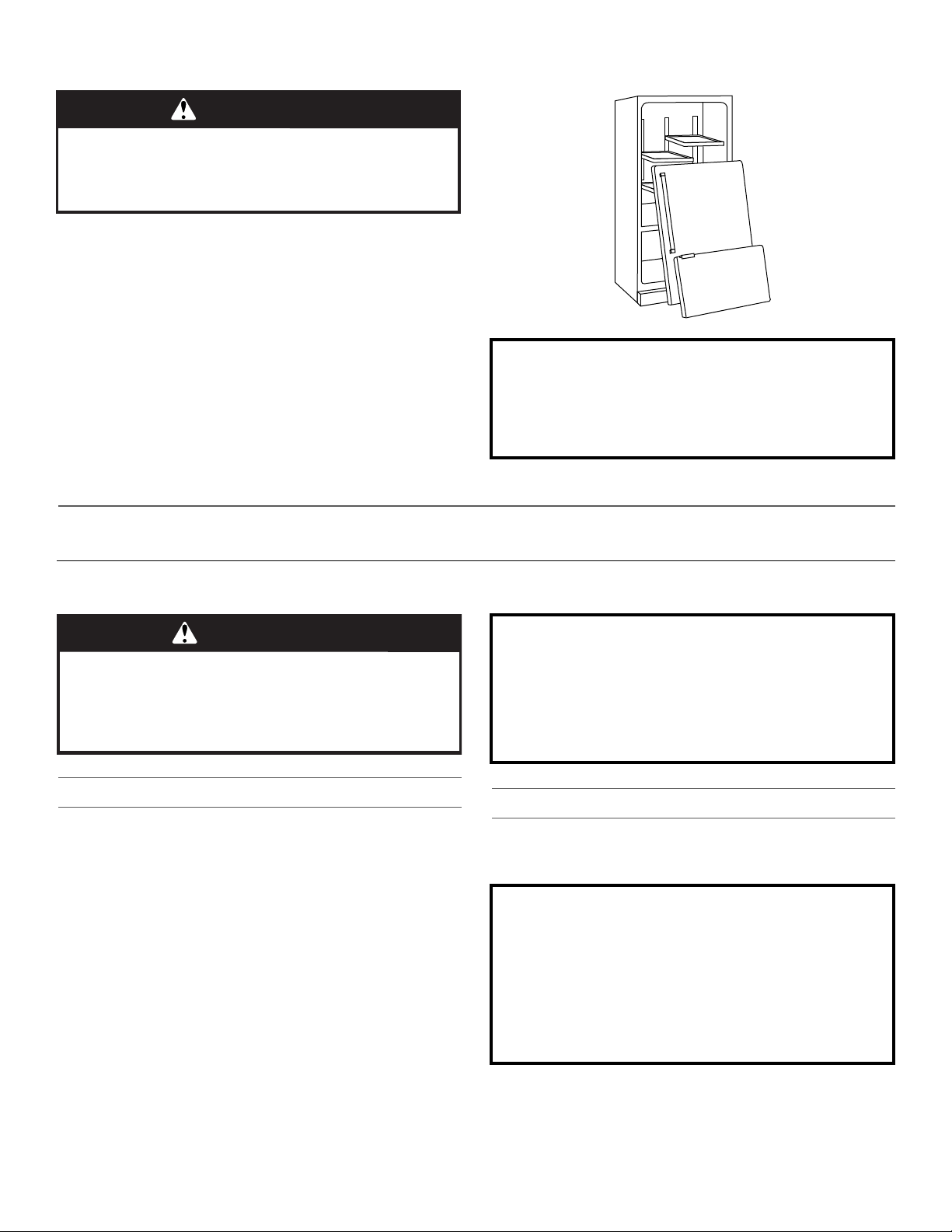
Proper Disposal of Your Old Refrigerator
WARNING
Suffocation Hazard
Remove doors from your old refrigerator.
Failure to do so can result in death or brain damage.
Important information to know about disposal of
refrigerants:
Dispose of refrigerator in accordance with Federal and Local
regulations. Refrigerants must be evacuated by a licensed,
EPA certified refrigerant technician in accordance with
established procedures.
WARNING
Excessive Weight Hazard
Use two or more people to move and install
refrigerator.
Failure to do so can result in back or other injury.
When Moving Your Refrigerator:
Your refrigerator is heavy. When moving the refrigerator for
cleaning or service, be sure to cover the floor with
cardboard or hardboard to avoid floor damage. Always pull
the refrigerator straight out when moving it. Do not wiggle or
“walk” the refrigerator when trying to move it, as floor
damage could occur.
Important information to know about glass shelves
and covers:
Do not clean glass shelves or covers with warm water when
they are cold. Shelves and covers may break if exposed to
sudden temperature changes or impact, such as bumping.
Tempered glass is designed to shatter into many small,
pebble-size pieces. This is normal. Glass shelves and covers
are heavy. Use both hands when removing them to avoid
dropping.
IMPORTANT: Child entrapment and suffocation are not problems
of the past. Junked or abandoned refrigerators are still dangerous
– even if they will sit for “just a few days.” If you are getting rid of
your old refrigerator, please follow these instructions to help
prevent accidents.
Before You Throw Away Your Old Refrigerator or Freezer:
■ Take off the doors.
■ Leave the shelves in place so that children may not easily
climb inside.
INSTALLATION INSTRUCTIONS
Unpack the Refrigerator
Remove the Packaging
■ Remove tape and glue residue from surfaces before turning
on the refrigerator. Rub a small amount of liquid dish soap
over the adhesive with your fingers. Wipe with warm water
and dry.
■ Do not use sharp instruments, rubbing alcohol, flammable
fluids, or abrasive cleaners to remove tape or glue. These
products can damage the surface of your refrigerator. For
more information, see “Refrigerator Safety.”
■ Dispose of/recycle all packaging materials.
Clean Before Using
After you remove all of the packaging materials, clean the inside of
your refrigerator before using it. See the cleaning instructions in
“Refrigerator Care.”
333333
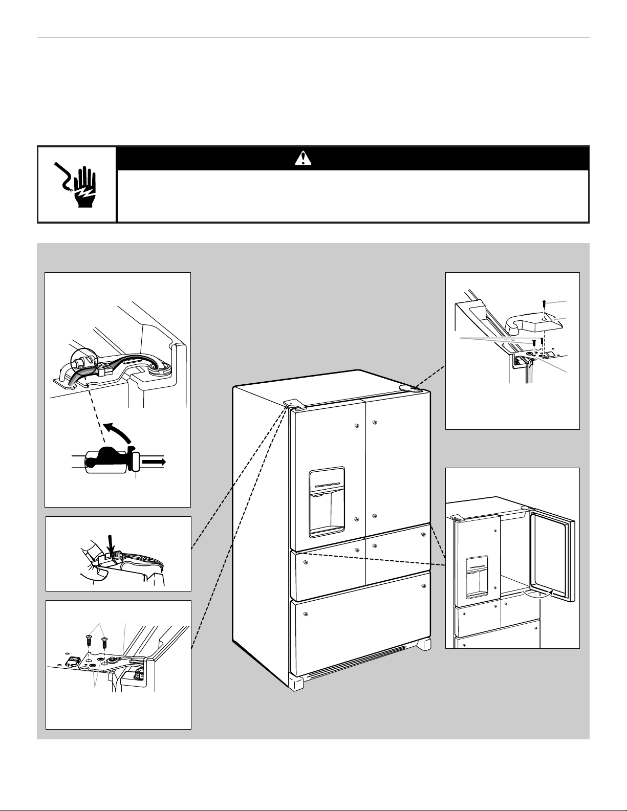
Remove and Replace Refrigerator Doors
WARNING
Electrical Shock Hazard
Disconnect power before removing doors.
Failure to do so can result in death or electrical shock.
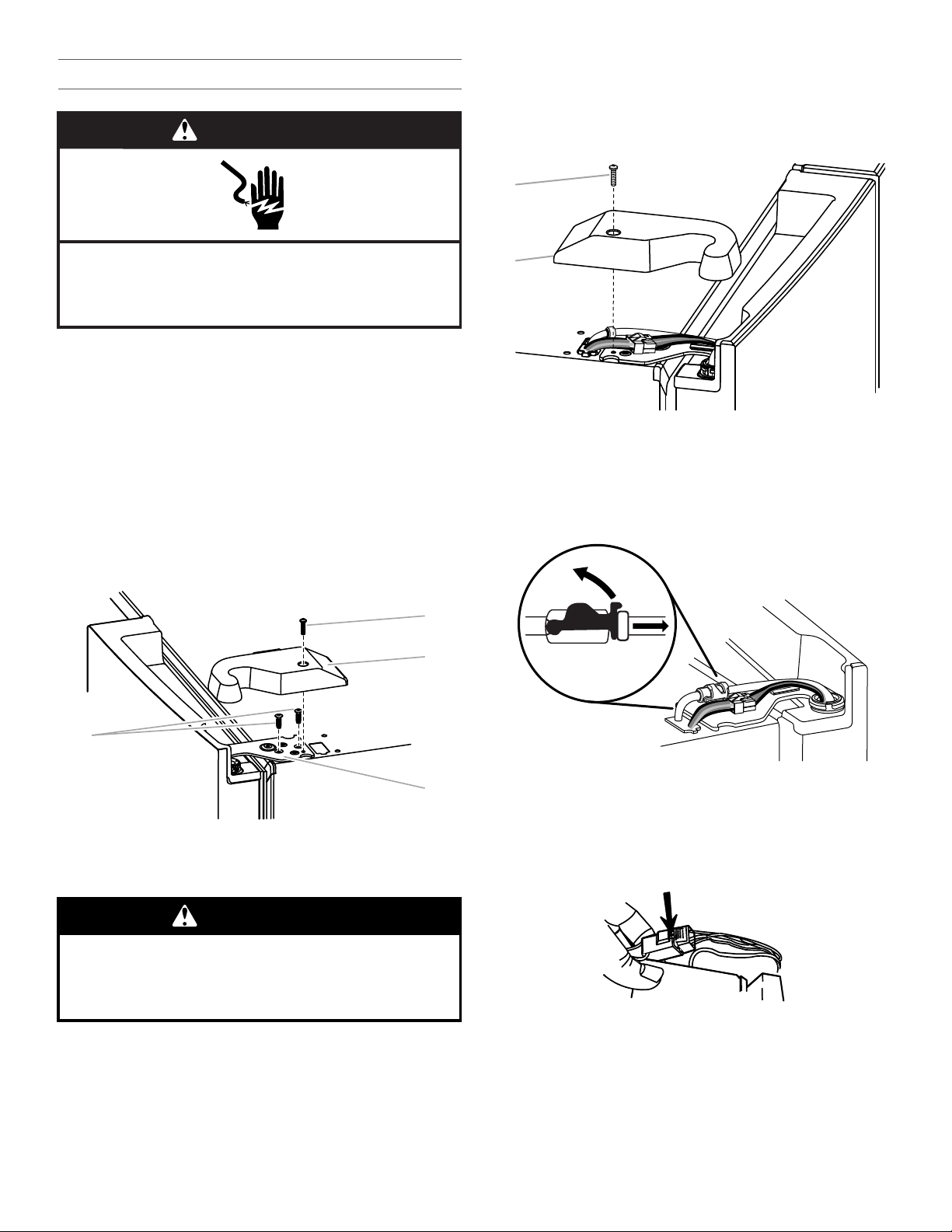
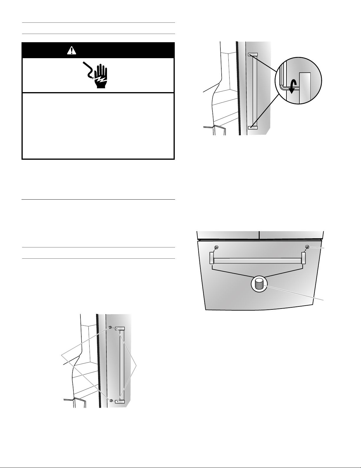
Door Removal and Replacement
Wiring Plug
Top Left Hinge
BA
C
A. ³⁄₁₆" Internal Hex-Head Screws
B. Ground Wire (Do Not Remove)
C. Do Not Remove Screws
Water Dispenser
Tubing Connection
A
A. Outer Ring
Top Right Hinge
A. ³⁄₁₆"
Internal Hex-Head Screws
B. Hinge Cover Screw
C. Top Hinge Cover
D. Top Hinge
C
B
A
D
90˚
Door at 90˚ Angle
to Cabinet
NOTE: Measure the width of your door opening to see whether or not you need to remove the refrigerator doors to move the refrigerator
into your home. If door removal is necessary, see the following instructions.
IMPORTANT: If the refrigerator was previously installed and you are moving it out of the home, before you begin, turn the refrigerator
control OFF. Unplug the refrigerator or disconnect power. Remove food and adjustable door or utility bins from doors.
Gather the required tools and read all instructions before removing doors.
TOOLS NEEDED: ³⁄₁₆" hex key and a #2 Phillips screwdriver
444444
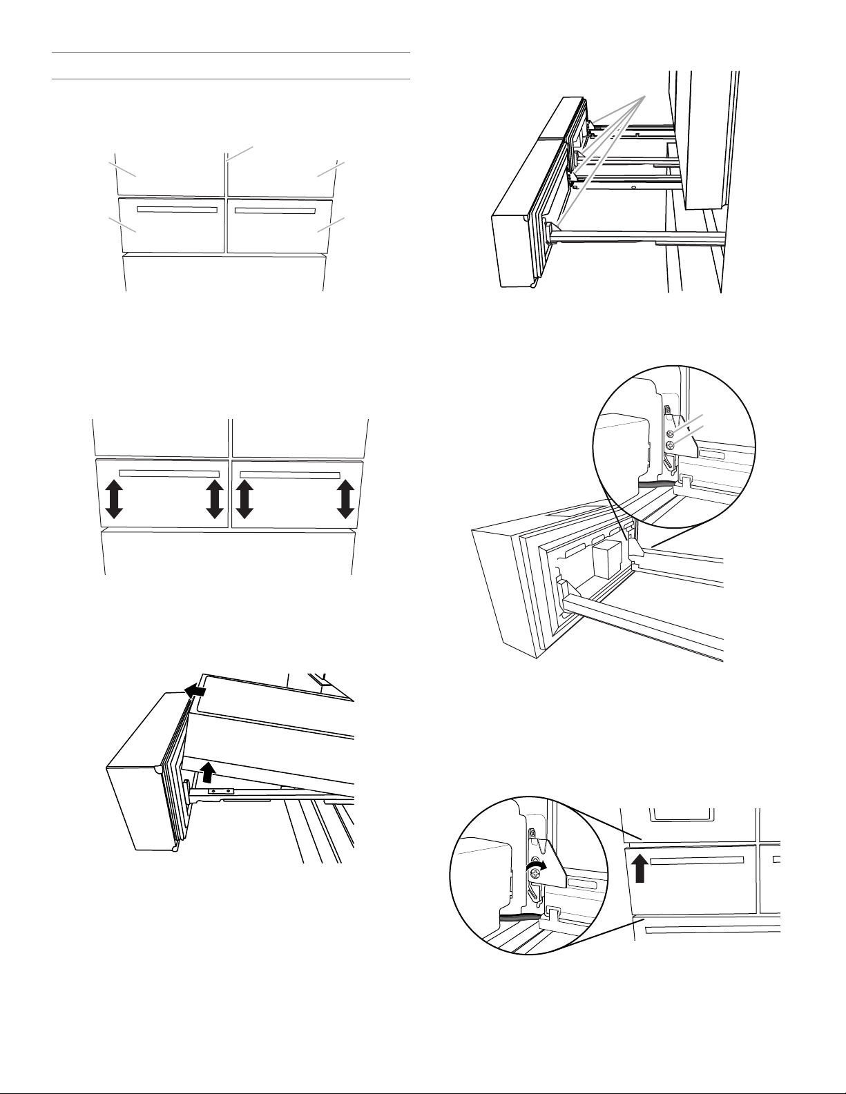
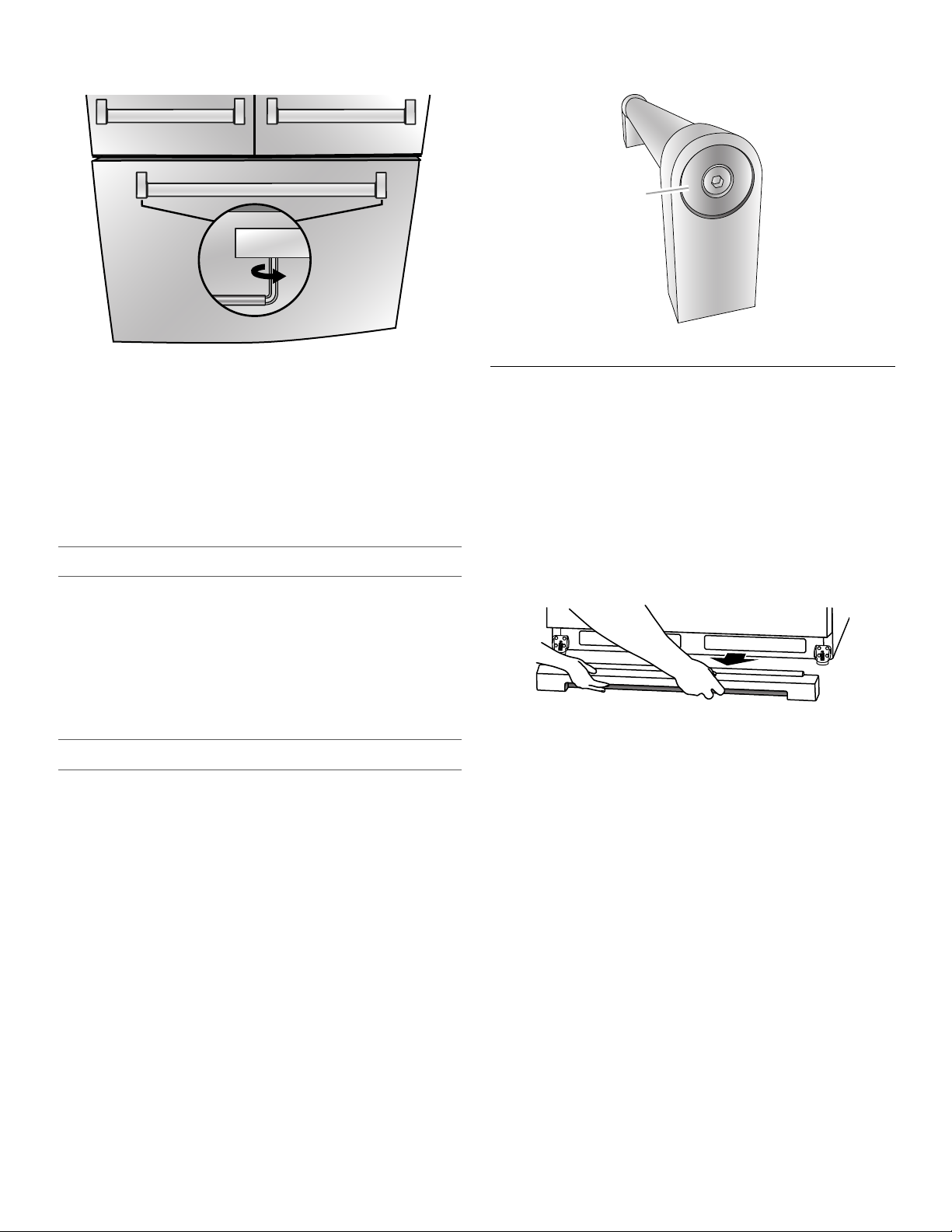
Bottom Door Hinge
90˚
A
B
A
90°
A
For your convenience, the refrigerator doors have bottom hinges
with door closers. These closers allow the doors to swing fully
closed with just a gentle push.
IMPORTANT: So that the closers feature will operate properly, the
doors must be removed only when open to a 90° angle to the front
of the cabinet. If one or both doors were not at a 90° angle when
removed, the bottom door hinge must be reset.
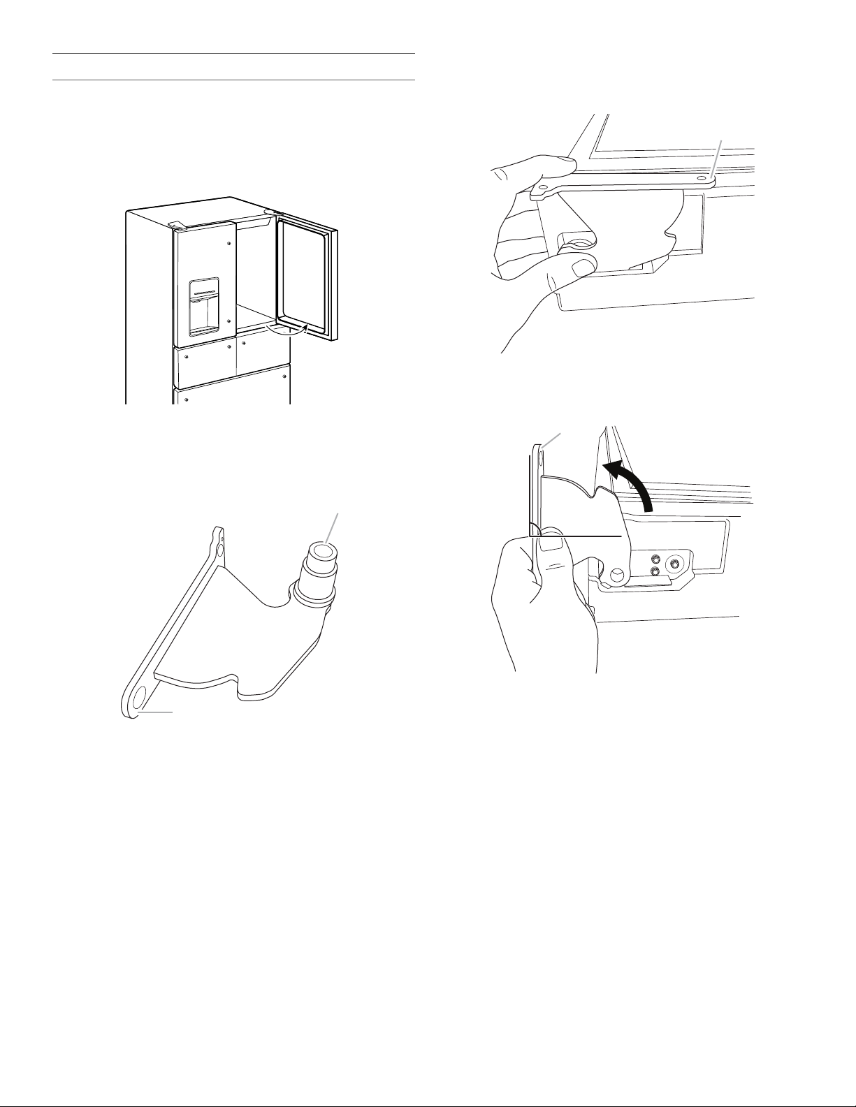
Reset the Door Hinge
1. Lift the door from the bottom hinge pin and place it on a flat
surface.
2. Using a driver with a #2 square bit, remove the bottom hinge
with the bushing from the cabinet.
3. Insert the bottom hinge and bushing into the corresponding
slot in the bottom of the door.
NOTE: Make sure that the base of the hinge is parallel to the
bottom of the door.
A. Hinge base parallel to the bottom edge of the door
4. Turn the hinge until the hinge base is at a 90° angle to the
bottom edge of the door.
A. Hinge base turned to a 90° angle with the
bottom edge of the door
A. Bushing
B. Hinge base
5. Remove the hinge from the door. Using a driver with a
#2 square bit, reattach the bottom hinge to the refrigerator
cabinet.
6. The hinge is now reset and prepared for the door to be
replaced. See “Replace Refrigerator Doors” later in this
section.
555555
Remove Refrigerator Doors
WARNING
Electrical Shock Hazard
Disconnect power before removing doors.
Failure to do so can result in death or electrical shock.
A
B
C
D
WARNING
Excessive Weight Hazard
Use two or more people to lift the refrigerator door.
Failure to do so can result in back or other injury.
A
B
Remove Right-Hand Refrigerator Door
1. Unplug refrigerator or disconnect power.
2. Keep the refrigerator doors closed until you are ready to lift
them free from the cabinet.
NOTE: Provide additional support for the refrigerator door
while the hinges are being removed. Do not depend on the
door gasket magnets to hold the door in place while you are
working.
3. Using a Phillips screwdriver, remove the cover from the top
hinge.
4. Using the ³⁄₁₆" hex key, remove the two internal hex-head
screws from the top hinge, and set aside.
NOTE: Do not remove the two locator screws. These screws
will help you align the hinge when you replace the door.
Remove Left-Hand Refrigerator Door
IMPORTANT: The tubing and wiring for the water dispenser run
through the left-hand door hinge, so they must be disconnected
before removing the door.
1. Using a Phillips screwdriver, remove the cover from the top
hinge.
A. Top hinge cover screwB.Top hinge cover
2. Disconnect the water dispenser tubing located on top of the
door hinge by firmly pulling up on the clasp. Then, pull the
tubing out of the fitting.
NOTE: The water dispenser tubing remains attached to the
left-hand refrigerator door.
A. Top hinge cover screw
B. Top hinge cover
5. Open the door until it is at a 90° angle to the front of the
cabinet.
6. Lift the refrigerator door from the bottom hinge pin. The top
hinge will come away with the door.
C.
³⁄₁₆
" Internal hex-head screws
D. Top hinge
666666
3. Disconnect the wiring plug located on top of the door hinge.
■ Grasp each side of the wiring plug. With your left thumb,
press down to release the catch and pull the sections of
the plug apart.
NOTE: Do not remove the green, ground wire. It should
remain attached to the door hinge.
4. Using the ³⁄₁₆" hex key wrench, remove the two internal
hex-head screws from the top hinge and set aside.
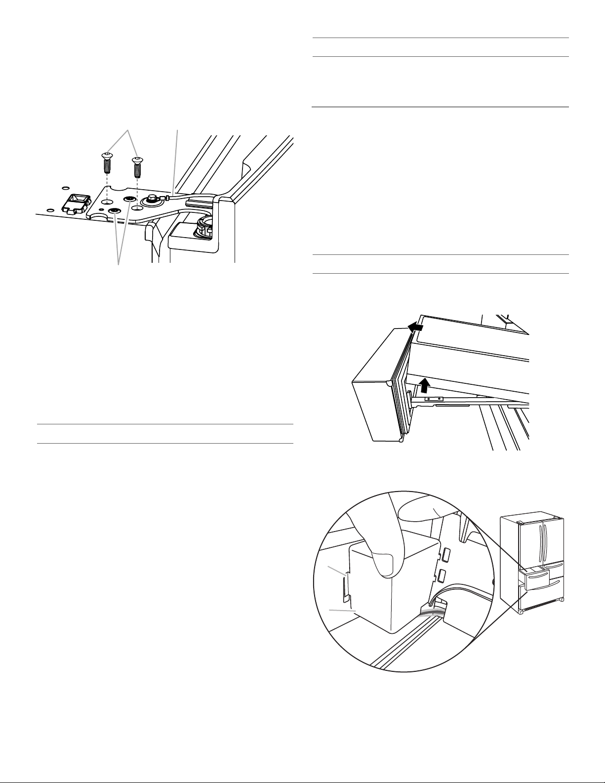
NOTES:
A B
C
A
B
■ Provide additional support for the refrigerator door while
the hinges are being removed. Do not depend on the door
gasket magnets to hold the door in place while you are
working.
■ Do not remove the two locator screws. These screws will
help you align the hinge when you replace the door.
Final Steps
1. Completely tighten the four internal hex-head screws (two on
the right-hand door hinge and two on the left-hand door
hinge).
2. Replace both top hinge covers.
Remove and Replace Drawer Fronts
Depending on the width of your door opening, it may be
necessary to remove the drawer fronts to move the refrigerator
into your home.
IMPORTANT:
■ If the refrigerator was previously installed and you are moving
it out of the home, before you begin, turn the refrigerator
control OFF, and unplug the refrigerator or disconnect power.
Remove food from the drawers.
■ Two people may be required to remove and replace the
drawer fronts.
Tools Needed: Flat-blade screwdriver
Refrigerated Drawers
³⁄₁₆
" Internal hex-head screws
A.
B. Ground wire (do not remove)
C. Locator screws (do not
remove)
5. Open the door until it is at a 90° angle to the front of the
cabinet.
6. Lift the refrigerator door from the bottom hinge pin. The top
hinge will come away with the door.
NOTE: It may not be necessary to remove the bottom hinges
and brake feet assemblies to move the refrigerator through a
doorway.
■ Only if necessary, use a driver with a #2 square bit tip to
remove the bottom hinges and a ³⁄₈" nut driver to remove
the brake feet screws.
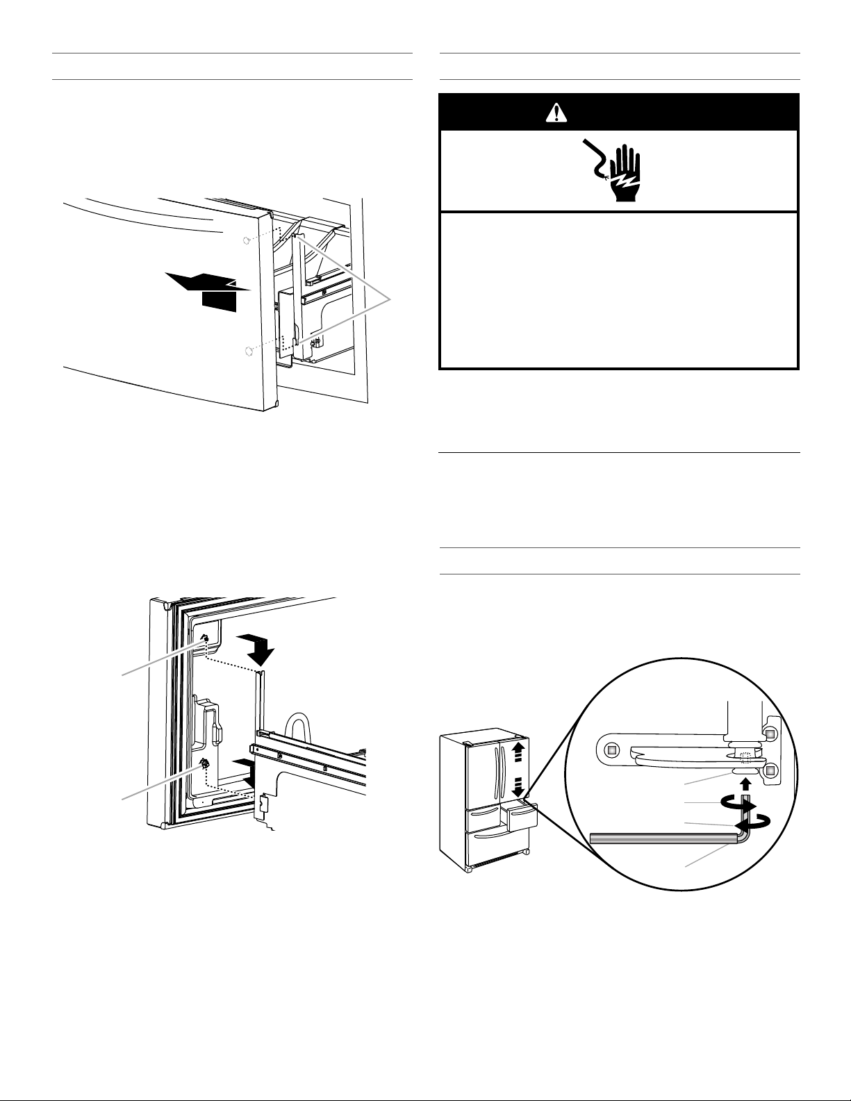
Replace Refrigerator Doors
IMPORTANT: To avoid damage to the refrigerator doors, they
must be replaced at a 90° angle to the front of the cabinet. You
should not have to force the door onto the hinge if it is at the
correct angle.
Replace Right-Hand Refrigerator Door
1. Holding the right-hand door at a 90° angle to the front of the
cabinet, set the door onto the bottom hinge pin.
2. Insert the top hinge pin into the open hole in the top of the
refrigerator door.
3. Using the two ³⁄₁₆" internal hex-head screws, fasten the hinge
to the cabinet. Do not tighten the screws completely.
Replace Left-Hand Refrigerator Door
IMPORTANT: Do not intertwine the water tubing and wiring
bundles when reconnecting them.
1. Holding the left-hand door at a 90° angle to the front of the
cabinet, set the door onto the bottom hinge pin.
2. Using the two ³⁄₁₆" internal hex-head screws, fasten the hinge
to the cabinet. Do not tighten the screws completely.
3. Reconnect the water dispenser tubing.
Style 1 - Insert the tubing into the fitting until it stops and the
outer ring is touching the face of fitting.
Style 2 - Insert the tubing firmly into the fitting until it stops.
Close the clasp around the tubing. The clasp snaps into place
between the fitting and the collar.
4. Reconnect the electrical wiring.
■ Push together the two sections of the wiring plug.
Remove the Drawer Fronts
1. Open the drawer to its full extension. Grasp the sides of the
interior bin, and then lift up and out to remove.
2. Left-hand drawer only, remove the wiring connection cover.
Press in on the side of the cover to release the tab from the
slot, and then pull the cover away from the bracket.
A. Cover tab
B. Wiring connection cover
777777
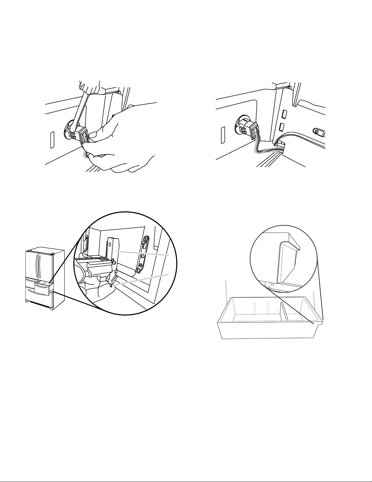
3. Left-hand drawer only, disconnect the wiring.
A
B
A
B
NOTE: The drawer front of the left-hand refrigerated drawer is
connected to the temperature control by wires running
underneath the drawer glide. Before removing the drawer
front, the wires must be disconnected.
■ On one side of the wiring connector, insert the screwdriver
blade between the connector tab and the connector to
release. Repeat for the opposite side. Pull the wiring
connector apart.
4. Remove the drawer front.
■ Push up on the lever at the bottom of the drawer glide
bracket to release the drawer front from the bracket.
■ Lift the drawer front up and off the drawer glide brackets.
3. Left-hand drawer only, reconnect wiring.
■ Align the two ends of the wiring connector and push them
together until you hear a “click” sound and feel the tabs
snap into place on the connector.
■ Gently pull on the wiring connection to ensure the wiring
connection is completely seated. Replace the wiring
cover.
NOTE: The wiring connection must be complete for the
drawer temperature control to operate.
4. Left-hand drawer only, replace the wiring connection cover.
5. Replace the drawer bins onto the drawer glides with the rear
side of the bin facing the back of the refrigerator as shown.
IMPORTANT: The Door Ajar alarm will sound if the interior
drawer bins are not replaced correctly. The bins are designed
with a specific front and rear. They must be placed into the
drawers, as shown, so that the refrigerated drawers will close
and operate properly.
A. Drawer glide bracket B. Release lever
5. Slide the drawer glides back into the refrigerator.
Replace the Drawer Fronts
1. Pull out the drawer glides until they are fully extended.
2. Push up on the lever at the bottom of the drawer glide bracket
to open. Insert the drawer front bracket into the drawer glide
bracket and release the lever.
NOTE: It helps if one person holds the drawer glides steady
while another person aligns the drawer front and connects the
brackets.
888888
A. Faces back of refrigerator (insert first)
B. Faces front of refrigerator
Freezer Drawer
A
A
B
Electrical Shock Hazard
Plug into a grounded 3 prong outlet.
Do not remove ground prong.
Do not use an adapter.
Do not use an extension cord.
Failure to follow these instructions can result in death,
fire, or electrical shock.
WARNING
A
B
C
D
Remove Drawer Front
1. Open the freezer drawer to its full extension.
2. Loosen the two top screws that fasten the drawer front to the
drawer glides. The two screws (one on the left-hand side and
one on the right-hand side) are located inside the drawer front.
3. Lift up on the drawer front to release the plastic studs from the
drawer glide bracket slots.
A. Drawer glide bracket slots
4. Slide the drawer glides back into the freezer.
Replace Drawer Front
1. Pull out the freezer drawer glides to their full extension.
2. Holding the drawer front by its sides, align the two plastic
studs, located at the bottom, inside the drawer front, with the
drawer glide bracket slots.
NOTE: It helps if one person holds the drawer glides steady
while another person aligns the drawer front and inserts the
studs into the slots.
Final Steps
1. Plug into a grounded 3 prong outlet.
2. Reset the controls. See “Using the Control(s)” and
“Temperature Controlled Exterior Drawer.”
3. Return all removable parts and the food to the drawers.
Align Doors and Drawers
Once the doors and drawer fronts are replaced on the refrigerator,
you may notice that the doors appear angled or that they are no
longer level. Both the refrigerator doors and refrigerated drawers
are adjustable.
Align Refrigerator Door
Tools Provided: ¹⁄₈" hex key
1. Keeping both refrigerator doors closed, pull out the right-hand
refrigerated drawer. Locate the bottom hinge pin of the
refrigerator door. The alignment screw is inside the bottom
hinge pin.
A. Drawer front screw
B. Drawer front plastic stud
3. Replace and tighten the two screws at the top of the drawer
front (one on the left-hand side and one on the right-hand
side).
A. Bottom hinge pin
B. Turn to the right to raise.
2. Insert the short end of the ¹⁄₈" hex key (packed with the Door
Handle Installation Instructions) into the bottom hinge pin until
it is fully engaged in the alignment screw.
■ To raise the door, turn the hex key to the right.
■ To lower the door, turn the hex key to the left.
3. Continue to turn the alignment screw until the doors are
aligned.
C. Turn to the left to lower.
D.
¹⁄₈
" Hex key
999999
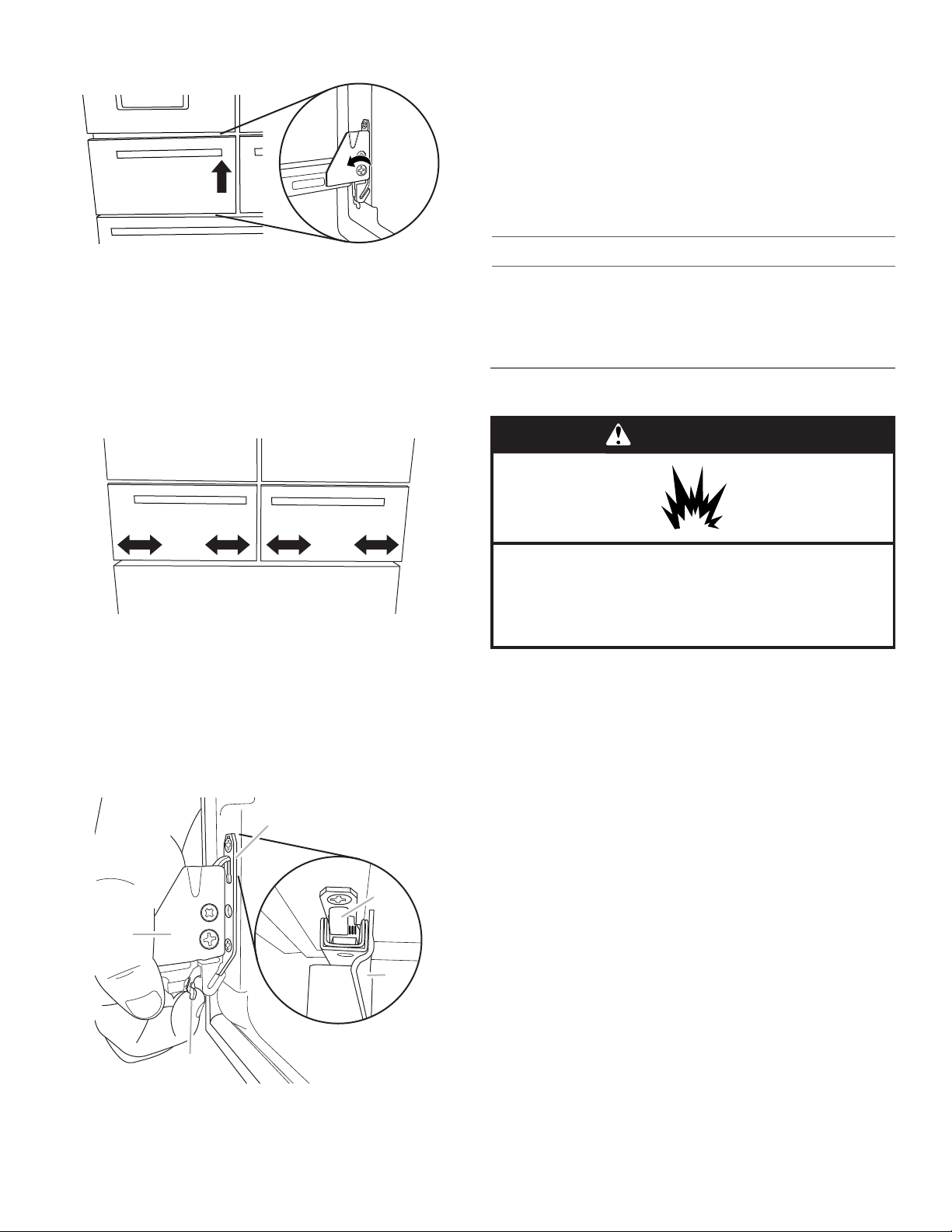
Align Refrigerated Drawer Fronts
A
B
C
B
C
A
A
B
When the drawer fronts are aligned, the width of the vertical space
(A) between the refrigerator doors (B) and the drawer fronts (C) is
the same thickness, and the drawers appear level.
3. Locate the drawer glide brackets (A).
Aligning the drawer fronts is a two-step process. The first step is
to adjust the drawer fronts up and down. The second step shifts
the drawer fronts from side to side. Visually inspect the
refrigerator for alignment and adjust the drawer fronts as needed.
Step 1 - Adjust the Drawer Fronts Up/Down
IMPORTANT: Each refrigerated drawer can be adjusted up and
down on both the left and the right sides.
Tools Needed: Phillips screwdriver
1. With the drawers closed, identify the drawer front that needs
to be raised or lowered.
2. Open the drawer to its full extension. Grasp the sides of the
interior bin, and then lift it up and out to remove.
A. Drawer glide brackets
4. Insert the Phillips screwdriver into screw (A) and turn
counterclockwise to loosen the drawer front.
A. Tightening screw
B. Adjusting screw
5. Insert the Phillips screwdriver into screw (B) to adjust the
drawer front.
IMPORTANT: The direction you turn screw (B) depends on
which side of the drawer you are adjusting.
Left-Hand Side Drawer Glide
■ To raise the drawer front, turn screw (B) clockwise.
■ To lower the drawer front, turn screw (B)
counterclockwise.
101010101010
Right-Hand Side Drawer Glide
A
B
C
B
A
WARNING
Explosion Hazard
Keep flammable materials and vapors, such as
gasoline, away from refrigerator.
Failure to do so can result in death, explosion, or fire.
5. Reposition the clip (A) onto the glide bracket (B) in the
direction you want to move the drawer front. Make sure that
the glide bracket is vertically level.
6. Release the lever (C) to lock the glide bracket into position.
7. Repeat steps 3 through 6 for the other side of the drawer
front.
NOTE: Adjust the clip (A) on the top of the second glide
bracket (B) so that it is in the same position as the side you
adjusted first
8. Close the drawer and visually inspect the gap. Repeat steps
2 though 7 until the drawer fronts are aligned.
■ To raise the drawer front, turn screw (B) counterclockwise.
■ To lower the drawer front, turn screw (B) clockwise.
6. Insert the Phillips screwdriver into screw (A), and turn
clockwise to tighten the drawer front.
7. Close the refrigerated drawer to check the alignment. Repeat
steps 2 through 6 until the drawer fronts are level.
Step 2 - Adjust the Drawer Fronts Side-to-Side
IMPORTANT: Each refrigerated drawer can be adjusted side-to-
side on both the left and right side.
1. With the drawers closed, identify the drawer that is not
aligned.
2. Open the drawer to its full extension. Grasp the sides of
the interior bin, and then lift it up and out to remove (see
step 1 for further details).
3. Locate the drawer glide brackets (see step 1 for further
details).
4. Starting with the glide bracket closest to the vertical gap,
press and hold the release lever (C) up. With your other hand,
lift the door clip (A) from the bracket (B).
Final Steps
1. Replace the interior drawer bins.
NOTE: The bins must be placed into the drawers correctly, so
that the refrigerated drawers will close and operate properly.
See “Remove and Replace Drawer Fronts.”
2. Close the refrigerated drawers.
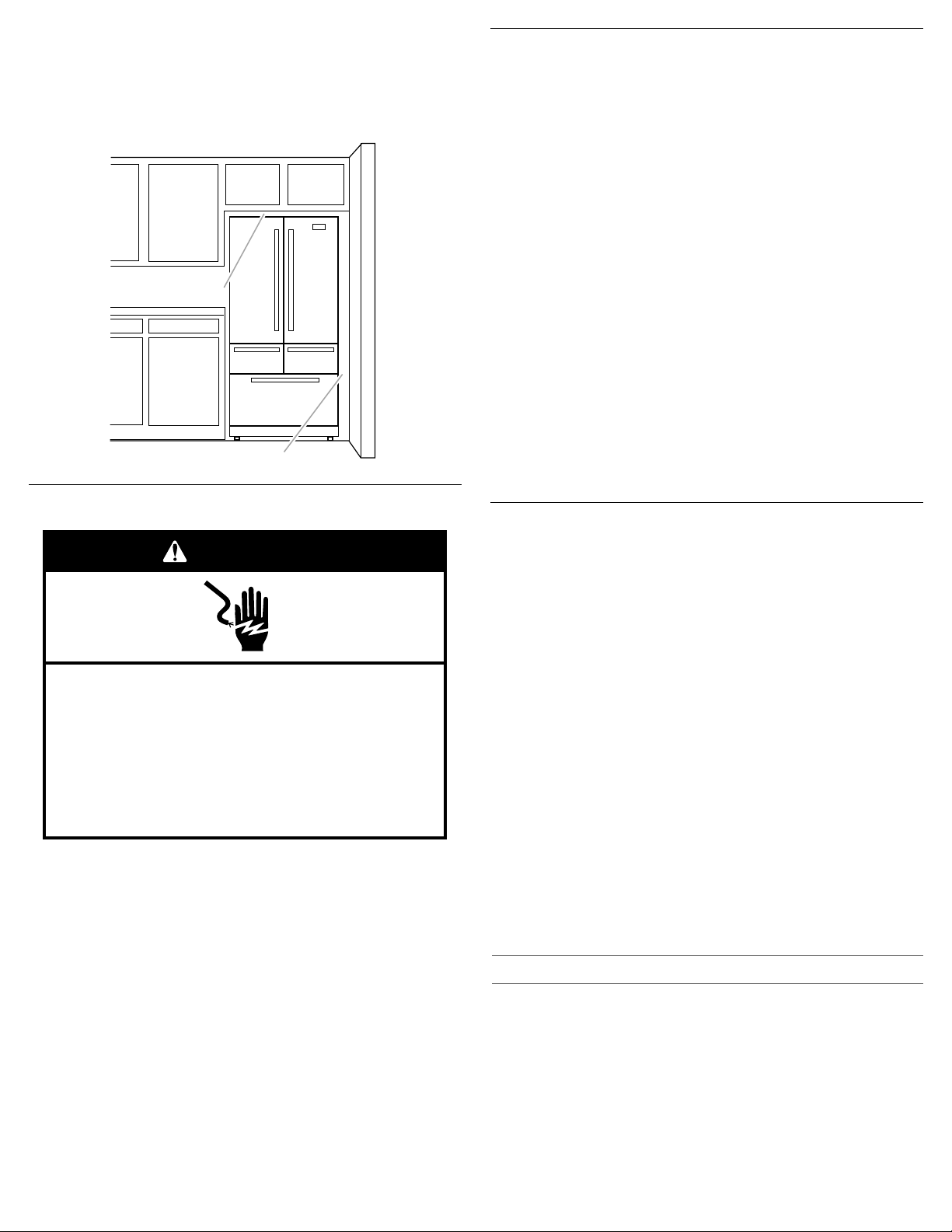
Location Requirements
IMPORTANT: This refrigerator is designed for indoor, household
use only.
To ensure proper ventilation for your refrigerator, allow for a
¹⁄₂" (1.25 cm) of space on each side and at the top. Allow for a
1" (2.54 cm) space behind the refrigerator. If your refrigerator has
an ice maker, allow extra space at the back for the water line
connections. When installing your refrigerator next to a fixed wall,
leave a 3³⁄₄" (9.5 cm) minimum space between the refrigerator and
wall to allow the door to swing open.
A. Drawer front clip
B. Drawer glide bracket
C. Release lever
111111111111
NOTE: This refrigerator is intended for use in a location where the
3³⁄₄
" (9.5 cm)
¹⁄₂
" (1.25 cm)
Electrical Shock Hazard
Plug into a grounded 3 prong outlet.
Do not remove ground prong.
Do not use an adapter.
Do not use an extension cord.
Failure to follow these instructions can result in death,
fire, or electrical shock.
WARNING
temperature ranges from a minimum of 55°F (13°C) to a maximum of
110°F (43°C). The preferred room temperature range for optimum
performance, which reduces electricity usage and provides superior
cooling, is between 60°F (15°C) and 90°F (32°C). It is recommended
that you do not install the refrigerator near a heat source, such as an
oven or radiator.
Electrical Requirements
Before you move your refrigerator into its final location, it is important
to make sure you have the proper electrical connection.
Recommended Grounding Method
A 115 volt, 60 Hz, AC only 15- or 20-amp fused, grounded electrical
supply is required. It is recommended that a separate circuit serving
only your refrigerator and approved accessories be provided. Use an
outlet that cannot be turned off by a switch. Do not use an
extension cord.
NOTE: Before performing any type of installation, cleaning, or
removing a light bulb, turn OFF Cooling, and then disconnect the
refrigerator from the electrical source. When you have finished,
reconnect the refrigerator to the electrical source and turn ON Cooling.
See “Using the Control(s).”
1212
Water Supply Requirements
A cold water supply with water pressure between 35 and 120 psi
(241 and 827 kPa) is required to operate the water dispenser and ice
maker. If you have questions about your water pressure, call a
licensed, qualified plumber.
NOTE: If the water pressure is less than what is required, the flow of
water from the water dispenser could decrease or ice cubes could be
hollow or irregular shaped.
Reverse Osmosis Water Supply
IMPORTANT: The pressure of the water supply coming out of a
reverse osmosis system going to the water inlet valve of the
refrigerator needs to be between 35 and 120 psi (241 and 827 kPa).
If a reverse osmosis water filtration system is connected to your cold
water supply, the water pressure to the reverse osmosis system needs
to be a minimum of 40 to 60 psi (276 to 414 kPa).
■ Check to see whether the sediment filter in the reverse osmosis
system is blocked. Replace the filter if necessary.
■ Allow the storage tank on the reverse osmosis system to refill after
heavy use. The tank capacity could be too small to keep up with
the requirements of the refrigerator.
NOTE: Faucet-mounted reverse osmosis systems are not
recommended.
■ If your refrigerator has a water filter, it may further reduce the water
pressure when used in conjunction with a reverse osmosis system.
Remove the water filter. See “Water Filtration System.”
If you have questions about your water pressure, call a licensed,
qualified plumber.
Connect the Water Supply
Read all directions before you begin.
IMPORTANT:
■ Plumbing shall be installed in accordance with the International
Plumbing Code and any local codes and ordinances.
■ The gray water tubing on the back of the refrigerator (which is used
to connect to the household water line) is a PEX (cross-linked
polyethylene) tube. Copper and PEX tubing connections from the
household water line to the refrigerator are acceptable and will
help avoid off-taste or odor in your ice or water. Check for leaks.
If PEX tubing is used instead of copper, we recommend the
following Part Numbers:
W10505928RP (7 ft [2.14 m] jacketed PEX),
8212547RP (5 ft [1.52 m] PEX), or
W10267701RP (25 ft [7.62 m] PEX).
■ Install tubing only in areas where temperatures will remain above
freezing.
Tools Needed:
Gather the required tools and parts before starting installation.
■ Flat-blade screwdriver
■ ⁷⁄₁₆" and ¹⁄₂" open-end wrenches or two adjustable wrenches
■ ¹⁄₄" nut driver
NOTE: Do not use a piercing-type or ³⁄₁₆" (4.76 mm) saddle valve which
reduces water flow and clogs easier.
Connect to Water Line
IMPORTANT: If you turn the refrigerator on before the water is
connected, turn OFF the ice maker.
1. Unplug refrigerator or disconnect power.
2. Turn OFF main water supply. Turn ON nearest faucet long enough
to clear line of water.
3. Use a quarter-turn shutoff valve or the equivalent, served by a ¹⁄₂"
household supply line.
NOTE: To allow sufficient water flow to the refrigerator, a
A
B
D
C
B CA
B
A
C
D
D
A B C
minimum ¹⁄₂" (12.7 mm) size household supply line is
recommended.
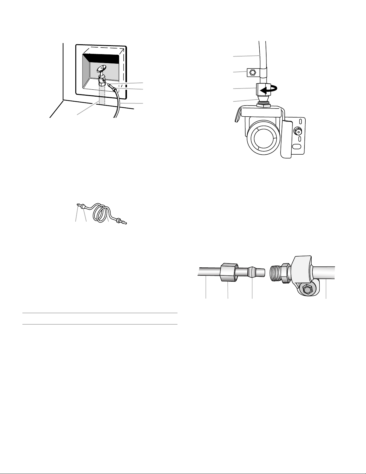
2. Create a service loop with the copper tubing. Avoid kinks
when coiling the copper tubing. Secure copper tubing to
refrigerator cabinet with a “P” clamp.
A. Sleeve
B. Nut
C. Copper tubing (to refrigerator)
D. Household supply line (½" minimum)
4. Now you are ready to connect the copper tubing to the shutoff
valve. Use ¹⁄₄" (6.35 mm) O.D. (outside diameter) soft copper
tubing to connect the shutoff valve and the refrigerator.
■ Ensure that you have the proper length needed for the job.
Be sure both ends of the copper tubing are cut square.
■ Slip compression sleeve and compression nut onto
copper tubing as shown. Insert end of tubing into outlet
end squarely as far as it will go. Screw compression nut
onto outlet end with adjustable wrench. Do not
overtighten.
3. Turn on water supply to refrigerator and check for leaks.
Correct any leaks.
Style 2
A. Copper tubing
B. “P” clamp
C. Compression nut
D. Compression sleeve
1. Unplug refrigerator or disconnect power.
2. Remove and discard the short, black plastic part from the end
of the water line inlet.
3. Thread the nut onto the end of the tubing. Tighten the nut by
A. Compression sleeve
B. Compression nut
C. Copper tubing
5. Place the free end of the tubing into a container or sink, and
hand. Then tighten it with a wrench two more turns. Do not
overtighten.
NOTE: To avoid rattling, be sure the copper tubing does not
touch the cabinet’s side wall or other parts inside the cabinet.
turn on main water supply to flush out tubing until water is
clear. Turn off shutoff valve on the water pipe.
NOTE: Always drain the water line before making the final
connection to the inlet of the water valve to avoid possible
water valve malfunction.
6. Bend the copper tubing to meet the water line inlet, which is
located on the back of the refrigerator cabinet as shown.
Leave a coil of copper tubing to allow the refrigerator to be
pulled out of the cabinet or away from the wall for service.
A. Household water line
Connect to Refrigerator
Follow the connection instructions specific to your model.
Style 1
1. Remove plastic cap from water valve inlet port. Attach the
copper tube to the valve inlet using a compression nut and
sleeve as shown. Tighten the compression nut. Do not
overtighten. Confirm copper tubing is secure by pulling on
copper tubing.
4. Install the water supply tube clamp around the water supply
5. Turn ON shutoff valve.
6. Check for leaks. Tighten any connections (including
7. On some models, the ice maker is equipped with a built-in
B. Nut (purchased)
line to reduce strain on the coupling.
connections at the valve) or nuts that leak.
water strainer. If your water conditions require a second water
strainer, install it in the ¹⁄₄" (6.35 mm) water line at either tube
C. Ferrule (purchased)
D. Refrigerator water tubing
connection. Obtain a water strainer from your appliance
dealer.
131313131313
Complete the Installation
Electrical Shock Hazard
Plug into a grounded 3 prong outlet.
Do not remove ground prong.
Do not use an adapter.
Do not use an extension cord.
Failure to follow these instructions can result in death,
fire, or electrical shock.
WARNING
A
B
A
B
1. Plug into a grounded 3 prong outlet.
2. Flush the water system. See “Water and Ice Dispensers.”
NOTE: Allow 24 hours to produce the first batch of ice. Discard
the first three batches of ice produced. Allow 3 days to completely
fill the ice storage bin.
Handle Installation and Removal
Parts Included: Refrigerator door handles (2), Refrigerated
drawer handles (2), Freezer drawer handle (1), ³⁄₃₂" hex key, spare
setscrew(s)
NOTE: The freezer drawer handle is longer than the door handles.
Handle style may vary by model.
4. While holding the handle, insert the short end of the hex key
into the upper hole and slightly rotate the hex key until it is
engaged in the setscrew.
5. Using a clockwise motion tighten the setscrew just until it
begins to contact the shoulder screw. Do not fully tighten.
6. Repeat steps 4 and 5 to fasten the lower setscrew.
7. Once both setscrews have been partially tightened as
instructed in the previous steps, fully tighten both setscrews.
IMPORTANT: When the screws feel tight, tighten them an
additional quarter-turn. The handle is not properly installed
without this extra tightening.
8. Repeat steps 2 through 7 to install the other handle onto the
adjacent refrigerator door.
Refrigerator and Freezer Drawers
1. With the drawer closed, place the handle onto the shoulder
screws so that the setscrews are facing down toward the floor.
Install Handles
Refrigerator Doors
NOTE: Handle mounting setscrews are preinstalled inside the
handle.
1. Remove the handles from the packaging inside the
refrigerator, and place them on a soft surface.
2. Open a refrigerator compartment door. On the closed door,
place a handle onto the shoulder screws so that the setscrews
are facing the adjacent door.
3. Firmly push the handle toward the door until the handle base
is flush against the door.
141414141414
A. Shoulder screws
B. Setscrews inside the handle
A. Shoulder screw
B. Setscrews inside the handle
2. Firmly push the handle toward the drawer until the handle
base is flush against the drawer.
3. Insert the short end of the hex key into the left-hand hole and
A
slightly rotate the hex key until it is engaged in the setscrew.
4. Using a left to right motion tighten the setscrew a quarter-turn
at a time just until it begins to contact the shoulder screw. Do
not fully tighten.
5. Repeat steps 11 and 12 to fasten the right-hand setscrew to
the shoulder screw.
6. Once both setscrews have been partially tightened as
instructed in the previous steps, fully tighten both setscrews.
IMPORTANT: When the screws feel tight, tighten them an
additional quarter-turn. The handle is not properly installed
without this extra tightening.
7. Save the hex key and all instructions.
Remove the Handles
1. While holding the handle, insert the short end of the hex key
into a setscrew hole, and slightly rotate the hex key until it is
engaged in the setscrew.
2. Using a right-to-left motion loosen the setscrew a quarter-turn
at a time.
3. Repeat steps 1 and 2 for the other setscrew. Slowly pull the
handle away from the door or drawer.
4. If necessary, use a Phillips screwdriver to remove the shoulder
screws from the door.
Remove and Replace Handle Medallions (optional)
The handles for your model have red medallions on the ends.
Replacement medallions are available for purchase. See
“Accessories” to order.
1. Using a ¹⁄₈" hex key, remove the medallion from the end of the
handle.
2. Replace medallion.
3. Using the fastener removed in Step 1, attach the medallion to
the handle.
A. Handle medallion
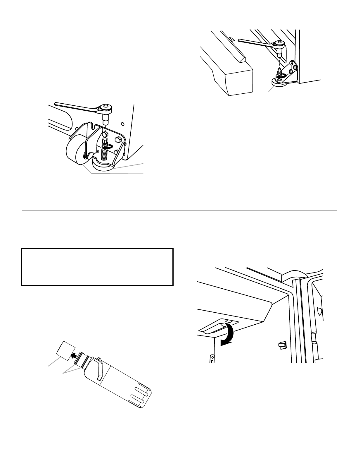
Refrigerator Leveling and Door Closing
The base grille covers the adjustable brake feet and roller
assemblies located at the bottom of the refrigerator below the
freezer drawer. Before making any adjustments, remove the base
grille and move the refrigerator to its final location.
Tools Needed: ¹⁄₄" hex driver
Tools Provided: ¹⁄₈" hex key
1. Remove the base grille. Using both hands, grasp the grille
firmly and pull it toward you. Open the freezer drawer to
access the brake feet.
NOTE: To allow the refrigerator to roll easier, raise the brake
feet by turning them counterclockwise. The front rollers will
be touching the floor.
2. Move the refrigerator to its final location.
3. Using the ¹⁄₄" hex driver, lower the brake feet. Turn them
clockwise until the rollers are off the floor and both brake feet
are snug against the floor. This keeps the refrigerator from
rolling forward when opening the refrigerator doors or freezer
drawer.
IMPORTANT: If you need to make further adjustments
involving the brake feet, you must turn both brake feet the
same amount to keep the refrigerator level.
151515151515
4. Make sure the doors close easily. If you are satisfied with the
A
¹⁄₄"
B
¹⁄₄"
A
Do not use with water that is microbiologically unsafe or
of unknown quality without adequate disinfection before
or after the system. Systems certified for cyst reduction
may be used on disinfected waters that may contain
filterable cysts.
B
A
door opening and closing, skip the next section and go to
Step 5. If, however, the doors do not close easily or the doors
pop open, adjust the tilt.
To Adjust the Cabinet Tilt:
■ Open the freezer drawer. Use a ¹⁄₄" hex nut driver to turn
both brake feet clockwise the same amount. This will raise
the front of the refrigerator. It may take several turns to
allow the doors to close easier.
NOTE: Having someone push against the top of the
refrigerator takes some weight off the brake feet. This
makes it easier to turn them.
Style 1
A. Brake foot
B. Front roller
Style 2
A. Brake foot
5. Make sure the refrigerator is steady. If the refrigerator seems
unsteady or rolls forward when a door or drawer is pulled
open, adjust the brake feet.
To Steady the Refrigerator:
■ Open the freezer drawer. Using a ¹⁄₄" hex driver, turn both
brake feet clockwise the same amount until the brake feet
are snug against the floor. Check again. If not satisfied,
continue to adjust the brake feet by half turns of the screw
until the refrigerator does not roll forward when the drawer
is opened.
NOTE: Having someone push against the top of the
refrigerator takes some weight off the brake feet. This
makes it easier to turn the screws.
6. Replace the base grille by aligning the ends of the grille with
the leveling assemblies on each side and snapping the grille
into place.
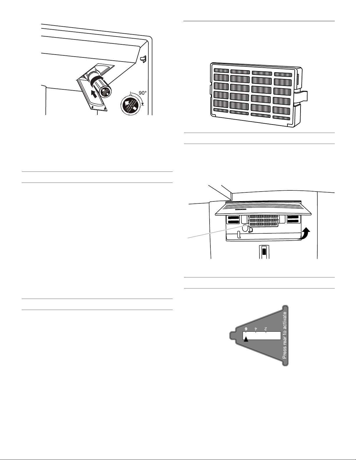
FILTERS AND ACCESSORIES
Install the Water Filter
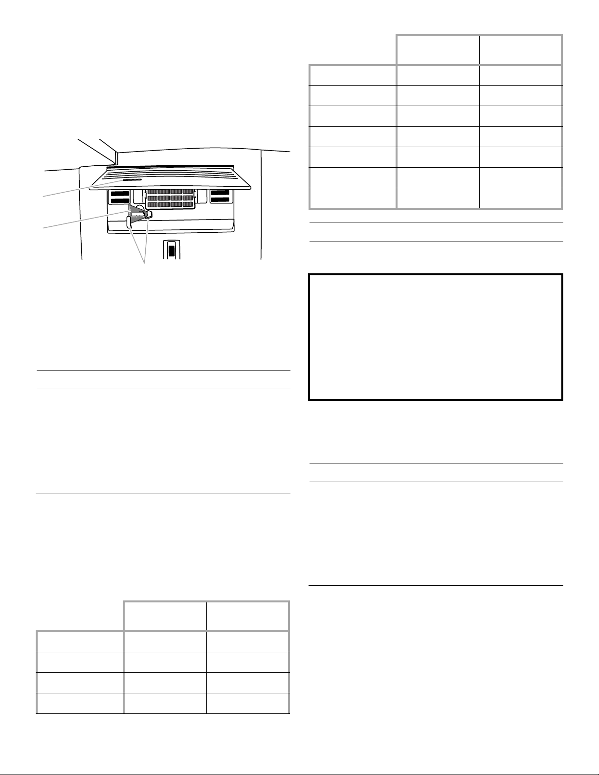
1. Locate the accessory packet in the refrigerator and remove
the water filter.
2. Take the water filter out of its packaging and remove the cover
from the O-rings. Be sure the O-rings are still in place after the
cover is removed.
A. O-ring cover
161616161616
B. O-rings
Water Filtration System
3. The water filter compartment is located in the right-hand side
of the refrigerator ceiling. Push up on the compartment door
to release the catch, and then lower the door.
4. Align the arrow on the water filter label with the cutout notch in
the filter housing and insert the filter into the housing.
5. Turn the filter clockwise 90 degrees (¹⁄₄ turn) until it locks into
the housing.
NOTE: If the filter is not correctly locked into the housing, the
water dispenser will not operate. Water will not flow from the
dispenser.
A
MONTHS
REPLACE
6. While the compartment door is still open, lift the filter up into
the compartment. Then, close the filter compartment door
completely.
7. Flush the water system. See “Flushing the Water Filter” in the
“Water and Ice Dispensers” section.
IMPORTANT: If you do not flush the water system, you may
experience dripping and/or decreased flow from the water
dispenser.
The Water Filter Status Light
Install Air Filter (on some models)
An air filter is 15 times more powerful than baking soda at
reducing common food odors inside the refrigerator.
On some models, your refrigerator's accessory packet includes
an air filter, which must be installed prior to use.
Installing the Air Filter
Install the air filter behind the vented door, located on the rear wall
near the top of the refrigerator compartment.
1. Remove the air filter from its packaging.
2. Lift open the vented door.
3. Snap the filter into place.
Press OPTIONS on the control panel to launch the Options menu.
Press OPTIONS, under Filter Status, again to display the
percentage of filter life remaining (from 99% to 0%). Press ICE/
WATER, under Back, to return to the Normal screen.
The water filter status lights will help you know when to change
your water filter.
■ ORDER FILTER (yellow) - it is almost time to change the water
filter. While you are dispensing water, “Order Filter” will blink
seven times and sound an alert tone three times.
■ REPLACE FILTER (red) - Replace the water filter. While you are
dispensing water, “Replace Filter” will blink seven times and
an alert tone will sound three times.
■ RESET the water filter status tracking feature. After you
replace the disposable filter with a new filter, closing the filter
compartment door will automatically reset the filter status
tracking feature. See “Using the Control(s).”
NOTE: “REPLACE FILTER” will remain illuminated if a filter is
not installed or is installed incorrectly.
Replace the Water Filter
To purchase a replacement water filter, see “Accessories” in the
User Guide, Use and Care Guide or User Instructions.
Replace the disposable water filter when indicated on the water
filter status display or at least every 6 months. If water flow to your
dispenser or ice maker decreases noticeably, change the water
filter sooner.
1. Locate the water filter compartment in the right-hand side of
the refrigerator ceiling. Push up to release and lower the
compartment door.
2. Turn the water filter counterclockwise (to the left), and pull it
straight out of the compartment.
NOTE: There may be some water in the filter. Some spilling
may occur. Use a towel to wipe up any spills.
3. Install the replacement water filter by following steps 2
through 7 in the “Install the Water Filter” section.
A. Air filter
Installing the Filter Status Indicator
The filter comes with a status indicator, which should be activated
and installed at the same time the air filter is installed.
1. Place the indicator face-down on a firm, flat surface.
2. Apply pressure to the bubble on the back of the indicator until
the bubble pops to activate the indicator.
171717171717
3. Lift open the vented air filter door. On some models, there are
B
A
C
CAUTION: IRRITANT
MAY IRRITATE EYES AND SKIN. DANGEROUS FUMES
FORM WHEN MIXED WITH OTHER PRODUCTS.
Do not mix with cleaning products containing ammonia,
bleach or acids. Do not get in eyes, on skin or clothing. Do
not breathe dust. Keep out of reach of children.
FIRST AID TREATMENT: Contains potassium
permanganate. If swallowed, call a Poison Control Center or
doctor immediately. Do not induce vomiting. If in eyes, rinse
with water for 15 minutes. If on skin, rinse with water.
notches behind the door.
Models with notches:
■ With the indicator screen facing outward, slide the
indicator down into the notches.
NOTE: The indicator will not easily slide into the notches
if the bubble has not been popped.
■ Close the air filter door, and check that the indicator is
visible through the window in the door.
A. Status indicator window
B. Air filter status indicator
C. Notches
Sensitivity to
Ethylene
Cantaloupe Medium High
Carrots Low Very Low
Citrus Fruit Medium Very Low
Grapes Low Very Low
Lettuce High Very Low
Pears High Very High
Spinach High Very Low
Ethylene
Production
Installing the Produce Preserver
For your convenience the suction mounted produce preserver can
be installed in either the crisper or the refrigerated drawers.
Models without notches:
■ Place the indicator somewhere it is easily visible - either
inside the refrigerator, or elsewhere in your kitchen or
home.
Replacing the Air Filter
The disposable air filter should be replaced every 6 months when
the status indicator has completely changed from white to red.
To order a replacement air filter, contact us. See “Accessories” in
the User Guide, Use and Care Guide or User Instructions for
information on ordering.
1. Remove the used air filter by squeezing in on the side tabs.
2. Remove the used status indicator.
3. Install the new air filter and filter status indicator using the
instructions in the previous sections.
Install Produce Preserver
(on some models)
The produce preserver absorbs ethylene to slow the ripening
process of many produce items. As a result, certain produce
items will stay fresh longer.
Ethylene production and sensitivity varies depending on the type
of fruit or vegetable. To preserve freshness, it is best to separate
produce with sensitivity to ethylene from fruits that produce
moderate to high amounts of ethylene.
Sensitivity to
Ethylene
Apples High Very High
Asparagus Medium Very Low
Berries Low Low
Broccoli High Very Low
181818181818
Ethylene
Production
1. Wash the interior of a drawer with a solution of mild dish soap
and warm water, and dry thoroughly.
2. Find the package containing the Produce Preserver inside the
refrigerator, and install the Produce Preserver into the drawer
according to the instructions provided in the package.
Replacing the Produce Preserver
The disposable packet(s) should be replaced every 6 months or
when the status indicator changes completely from white to red.
To order replacements, contact us. See “Accessories” for
information on ordering.
1. Remove the used packets from the produce preserver
housing.
2. Remove the used status indicator.
3. Install the replacement packets and status indicator using the
instructions included in the package.
Accessories
The following accessories are available for your refrigerator. To
order an accessory, contact us and ask for the part number.
In the U.S.A., visit our website www.kitchenaid.com or call
1-800-422-1230.
In Canada, visit our webpage www.kitchenaid.ca
or call 1-800-807-6777.
affresh® Stainless Steel Cleaner:
In U.S.A., order Part #W10355016
In Canada, order Part #W10355016B
affresh® Stainless Steel Wipes:
A
In U.S.A., order Part #W10355049
In Canada, order Part #W10355049B
®
affresh
In U.S.A., order Part #W10355010
In Canada, order Part #W10355010B
Water Filter:
In U.S.A., order Part #EDR2RXD1
In Canada, order Part #EDR2RXD1B
Air Filter:
Order Part #W10311524 or AIR1
Produce Preserver Starter kit:
Order Part #P1UB6S1
Produce Preserver Refill kit:
Order Part #P1KC6R1
Door Handle Medallions:
Order Part #W10762987 (Black)
Order Part #W10762993 (Chrome)
Kitchen & Appliance Cleaner:
REFRIGERATOR USE
Opening and Closing Doors
There are two refrigerator compartment doors. The doors can be
opened and closed either separately or together. There is also an
automatic closing mechanism so the door(s) will not
unintentionally be left open. If a door is open at a 40° or smaller
angle, the door will automatically, softly close.
IMPORTANT: If the doors do not automatically close at a 40° or
smaller angle, see the “Bottom Door Hinge” section.
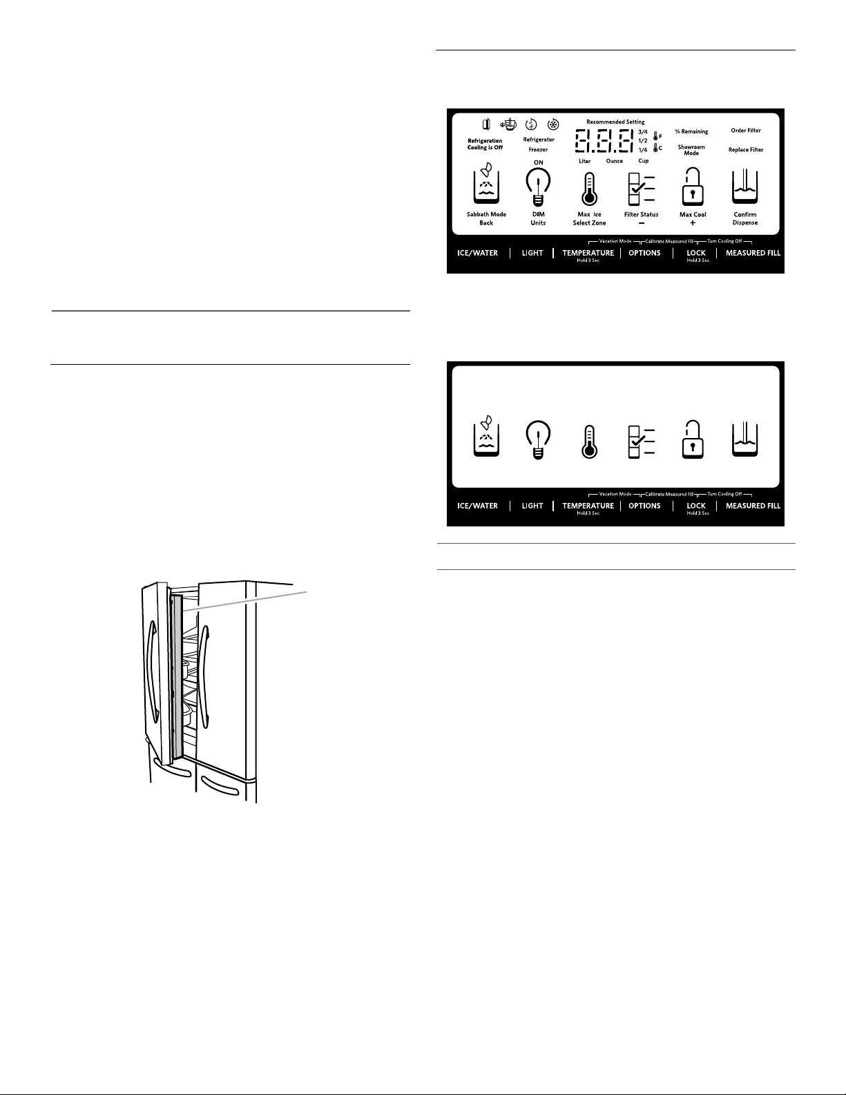
There is a vertically-hinged seal on the left refrigerator door.
■ When the left-side door is opened, the hinged seal
automatically folds inward so that it is out of the way.
■ When both doors are closed, the hinged seal automatically
forms a seal between the two doors.
A. Hinged seal
Using the Controls
The controls are located above the external dispenser.
IMPORTANT: The display screen on the dispenser control panel
will turn off automatically and enter “sleep” mode when the
control buttons and dispenser paddles have not been used for
2 minutes or more. Press any control button to reactivate the
display screen. The home screen will appear as shown.
Viewing and Adjusting Temperature Set Points
For your convenience, your refrigerator and freezer controls are
preset at the factory.
When you first install your refrigerator, make sure that the controls
are still set to the recommended set points. The factory
recommended set points are 37°F (3°C) for the refrigerator and
0°F (-18°C) for the freezer.
IMPORTANT:
■ Wait 24 hours before you put food into the refrigerator. If you
add food before the refrigerator has cooled completely, your
food may spoil.
NOTE: Adjusting the set points to a colder than
recommended setting will not cool the compartments any
faster.
■ If the temperature is too warm or too cold in the refrigerator or
freezer, first check the air vents to be sure they are not
blocked before adjusting the controls.
■ The recommended settings should be correct for normal
household use. The controls are set correctly when milk or
juice is as cold as you like and when ice cream is firm.
NOTE: Areas such as a garage, basement, or porch may have
higher humidity or extreme temperatures. You may need to
adjust the temperature away from the recommended settings
to accommodate for these conditions.
■ Wait at least 24 hours between adjustments. Recheck the
temperatures before other adjustments are made.
191919191919
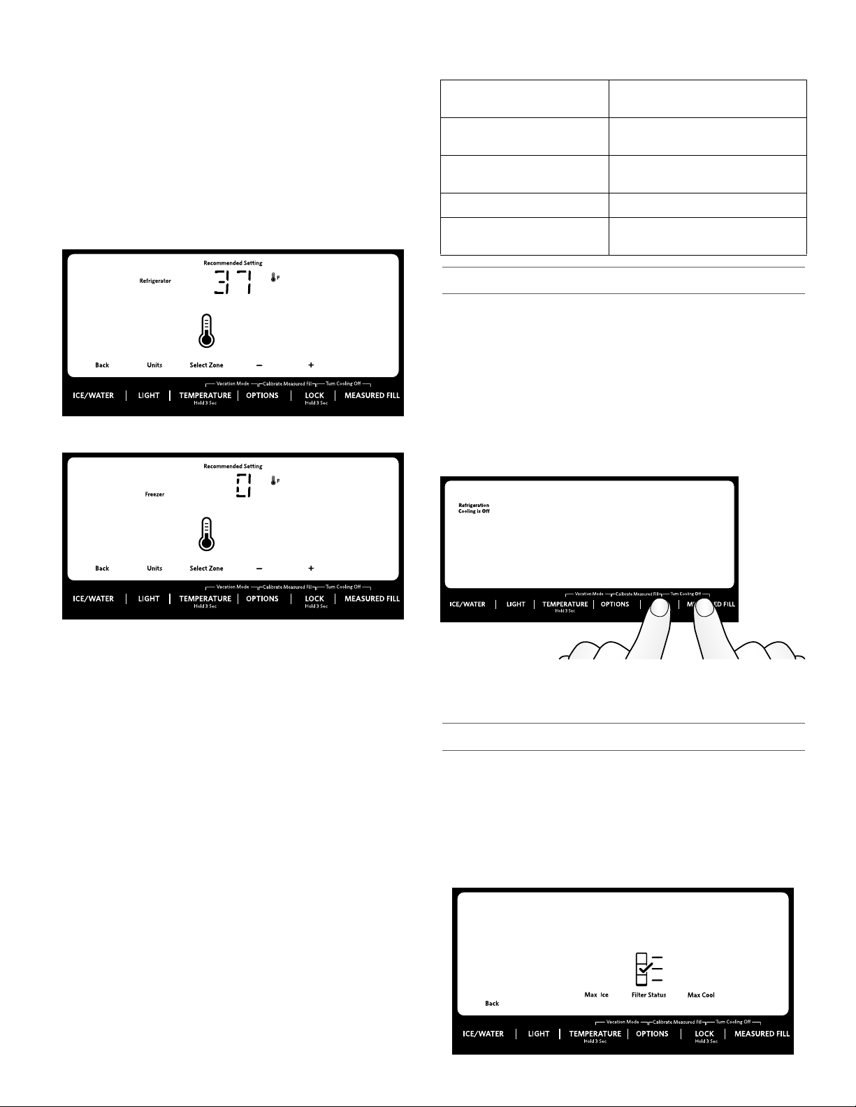
View Temperature Set Points
1. Press and hold TEMPERATURE for 3 seconds to activate
Temperature mode.
NOTE: To view temperature in degrees Celsius, press the
LIGHT button, under Units, when adjust mode is activated.
To return the display setting to Fahrenheit, press the LIGHT
button again.
When Temperature mode is activated, press TEMP to toggle
between Fridge and Freezer. The display will show the
temperature set point of the selected compartment, and
temperature adjusting information will appear on the display
screen.
Recommended Refrigerator Temperature
Recommended Freezer Temperature
When adjusting temperature set points,
use the following chart as a guide:
CONDITION: TEMPERATURE
ADJUSTMENT:
REFRIGERATOR too cold REFRIGERATOR Setting
1° higher
REFRIGERATOR too warm REFRIGERATOR Setting
1° lower
FREEZER too cold FREEZER Setting 1° higher
FREEZER too warm /
FREEZER Setting 1° lower
Too little ice
Cooling On/Off
Your refrigerator and freezer will not cool when cooling is
turned off.
■ To turn cooling off, press and hold the LOCK and MEASURED
FILL buttons at the same time for 3 seconds. The Cooling Off
icon will blink seven times and then remain lit as shown.
IMPORTANT:
■ To avoid unintentionally locking the dispenser or changing
other settings, press both buttons at exactly the same
time.
■ When cooling is off, the dispenser paddles and all controls
except Lock and Measured Fill are disabled.
Adjust Temperature Set Points
Refrigerator set point range: 33°F to 42°F (0°C to 5.5°C).
Freezer set point range: -5°F to 5°F (-21°C to -15°C).
1. When Temperature mode is activated, press TEMPERATURE
to select the Refrigerator zone. The display will show the
temperature set point of the selected compartment as shown.
2. Press LOCK to raise the set point, or press OPTIONS to lower
the set point.
3. When you have finished viewing (and adjusting if desired) the
refrigerator set point, press TEMPERATURE, under Select
Zone, to change the display to show the freezer set point.
When the zone has been changed, “FREEZER” appears on
the display screen.
4. Press the LOCK button to raise the set point, or press the
OPTIONS button to lower the set point.
Save/Confirm Temperature Settings
■ When you have finished adjusting both the refrigerator and
freezer set points, press MEASURED FILL to confirm and to
save the settings.
NOTE: To exit Temperature mode without saving changes, press
the ICE/WATER button under Back at any time, or allow about
60 seconds of inactivity. The temperature mode will turn off
automatically and return to the normal screen.
Press LOCK and MEASURED FILL at the same time.
■ Press and hold LOCK and MEASURED FILL for 3 seconds
again to turn cooling back on.
Options
IMPORTANT: All options are OFF (default) until selected.
■ Press the OPTIONS button to open the Options menu and
select among the Max Ice, Filter Status and Max Cool
features.
NOTE: “Max Cool” and “Max Ice” illuminate to indicate when
both features are on.
■ Press the ICE/WATER button at any time to return to the
Home screen.
202020202020
Max Ice
The Max Ice feature assists with temporary periods of heavy ice
use by increasing ice production. Once selected, the Max Ice
feature will remain on for 24 hours unless manually turned off.
■ To turn on the Max Ice feature, press the OPTIONS button to
access the Options menu, then press TEMPERATURE, under
Max Ice to activate the feature. When the feature is on, the
Max Ice icon will appear on the dispenser display screen.
■ To manually turn off the Max Ice feature, press the OPTIONS
button to enter Options mode (unless you are already in
Options mode), then press TEMPERATURE, under Max Ice,
again. When the feature has been turned off, the Max Ice icon
will disappear from the dispenser display.
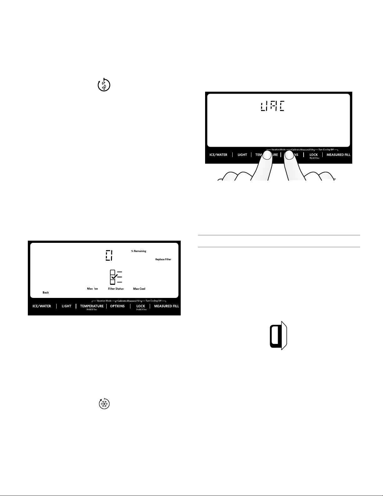
Filter Status
Displays the percentage of use remaining in the water filter (from
100% remaining to 0% remaining).
To access Filter Status, press the OPTIONS button to access the
Options menu, and then press OPTIONS, under Filter Status, to
display the percent of life remaining in the water filter.
ALSO
The water filter status lights will let you know when to change
your water filter.
■ ORDER FILTER (Yellow) - Order a replacement water filter.
■ REPLACE FILTER (Red) - Replace the water filter. Replacing
the disposable water filter will automatically reset the water
filter status tracking feature. See “Water Filtration System.”
NOTE: REPLACE FILTER will remain illuminated if a filter is
not installed or installed incorrectly.
Vacation Mode
In Vacation Mode, the freezer will defrost less often to conserve
energy.
■ To turn on Vacation mode, press and hold the TEMPERATURE
and OPTIONS buttons at the same time for 3 seconds. When
the feature is on, VAC will appear on the display as shown.
■ To turn off Vacation Mode, press and hold the TEMPERATURE
and OPTIONS buttons at the same time for 3 seconds. VAC
will disappear and the display will return to the settings as
they were before Vacation Mode was turned on.
NOTES:
■ During the first hour after Vacation Mode is turned on, opening
and closing the refrigerator door will not affect the setting.
After 1 hour has passed, opening and closing the refrigerator
door will turn off Vacation Mode.
■ While in Vacation Mode, if Max Ice is turned on or the Door
Ajar alarm sounds, Vacation Mode will be canceled.
Additional Features
Max Cool
The Max Cool feature assists with periods of high refrigerator
use, full grocery loads, or temporarily warm room temperatures.
Once selected, the Max Cool feature will remain on for 24 hours
unless manually turned off.
NOTE: If you adjust the refrigerator temperature set point, Max
Cool will turn off.
■ To turn on the Max Cool feature, press the OPTIONS button to
access the Options menu, then press LOCK, under Max Cool
to activate the feature. When the feature is on, the Max Cool
icon will appear on the dispenser display screen.
■ To manually turn off the Max Cool feature, press the OPTIONS
button to enter Options mode (unless you are already in
Options mode), then press LOCK, under Max Cool, again.
When the feature has been turned off, the Max Cool icon will
disappear from the dispenser display.
Door Ajar Alarm
The Door Ajar Alarm feature sounds an alarm when the refrigerator
door(s), drawers, and freezer drawer is open for 5 minutes and
cooling is turned on. The alarm will repeat every 2 minutes. Close
all doors and drawer to turn it off. The feature then is reset and will
reactivate when either door is left open again for 5 minutes.
■ NOTE: To mute the audible alarm while keeping the doors
open, such as while cleaning the inside of the refrigerator,
press any button on the control panel. The alarm sound will be
temporarily turned off, but the Door Ajar icon will still be
displayed on the dispenser control panel.
Disabling Sounds
■ To turn off control and dispenser sounds, press and hold ICE/
WATER and MEASURED FILL at the same time for 3 seconds.
All normal operating tones are disabled. Only alert tones will
be audible.
■ To turn all sounds back on, press and hold ICE/WATER and
MEASURED FILL at the same time for 3 seconds again.
Power Outage
The Power Outage indicator lets you know if the power supply to
the refrigerator has been off, and the freezer temperature has risen
to 18°F (-8°C) or higher.
The control panel temperature display will read “PO,” and an alert
tone will sound three times. “Confirm” will blink until you
acknowledge the power outage by pressing MEASURED FILL
under “Confirm.”
Once the power outage has been confirmed, the “PO” will
disappear, and the display will return to the Home screen.
212121212121
Showroom Mode
A
B
This mode is used only when the refrigerator is on display in a
retail store. If you unintentionally turn on Showroom mode, the
word “Showroom” will light up on the display. Exit Showroom
mode by pressing and holding LIGHT and LOCK at the same time
for 3 seconds.
Refrigerator Features
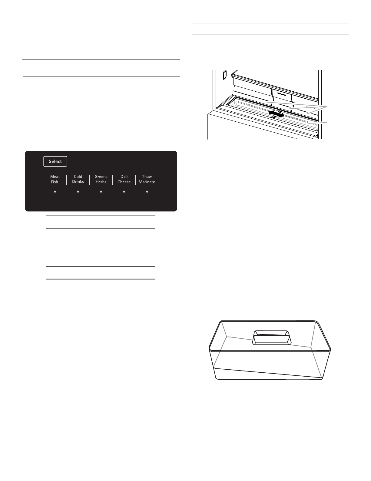
Temperature Controlled Exterior Drawer
IMPORTANT: The left-hand refrigerated drawer has its own
temperature control. This control sets the temperature for this
drawer only. The temperature for the right-hand drawer is set to
the same temperature as the main refrigerator compartment.
Temperatures have been preset for the storage of: Meat/Fish,
Cold Drinks, Greens/Herbs, Deli/Cheese and Thaw/Marinate.
These preset temperatures cannot be adjusted.
■ Press SELECT to toggle through the temperature settings.
The icon will illuminate when it is selected.
Meat/Fish 32°F (0°C)
Cold Drinks 34°F (1°C)
Greens/Herbs 36°F (2°C)
Deli/Cheese 38°F (3°C)
Thaw/Marinate 39°F (4°C)
Removable Interior Drawer Bins
The drawer bins are removable for ease in cleaning.
To remove and replace the interior bins:
1. To remove, grasp the sides of the bin and lift up and out.
2. To replace, with the rear of the bin facing the back of the
refrigerator, lower the bin onto the drawer glides. See
“Remove and Replace Drawer Fronts.”
Adjustable Drawer Bin Dividers
Each refrigerated drawer has an interior drawer bin with a divider
that can be inserted into one of three different positions, or
removed to customize the space for your food storage needs.
Easy Slide Bin
A shallow storage compartment with glass lids which slide from
side to side is located below and in front of the crisper drawers.
NOTE: This compartment is not temperature or humidity
controlled, so it is not recommended for storing leafy vegetables.
A. Crisper drawer handles
B. Easy Slide bin
To remove Easy Slide bin:
1. Remove all three crisper drawers.
2. Hold the upper sliding lid near the trim and lift up to remove.
Remove the lower lid.
3. Grasp the front of the bin with both hands, and lift up on the
front to remove.
To replace Easy Slide bin:
1. Slightly tilt the rear of the bin upward.
2. Align the center rib and tabs on the Easy Slide bin with the ribs
and slots in the cabinet.
3. Lower the bin into place.
Herb Box
A box to store herbs and the water to keep them fresh is located
within the Easy Slide bin. For your convenience, you can
reposition the herb box anywhere along the length of the bin.
1. Slide open one of the bin doors to access the herb box.
2. Remove the herb box from the bin using two hands. One hand
should hold the box while the other hand holds the lid.
3. Grasp the handle between your fingers and lift up to remove
the lid.
NOTE: The bottom of the herb box is angled so that the roots
of the herbs can be submerged in water while the leaves
remain dry.
222222222222
Shelves and Shelf Frames
Important information to know about glass shelves
and covers:
Do not clean glass shelves or covers with warm water when
they are cold. Shelves and covers may break if exposed to
sudden temperature changes or impact, such as bumping.
Tempered glass is designed to shatter into many small,
pebble-size pieces. This is normal. Glass shelves and covers
are heavy. Use both hands when removing them to avoid
dropping.
The shelves in your refrigerator are adjustable to meet your individual
storage needs.
Storing similar food items together in your refrigerator and adjusting
the shelves to fit different heights of items will make finding the exact
item you want easier. It will also reduce the amount of time the
refrigerator door is open, and save energy.
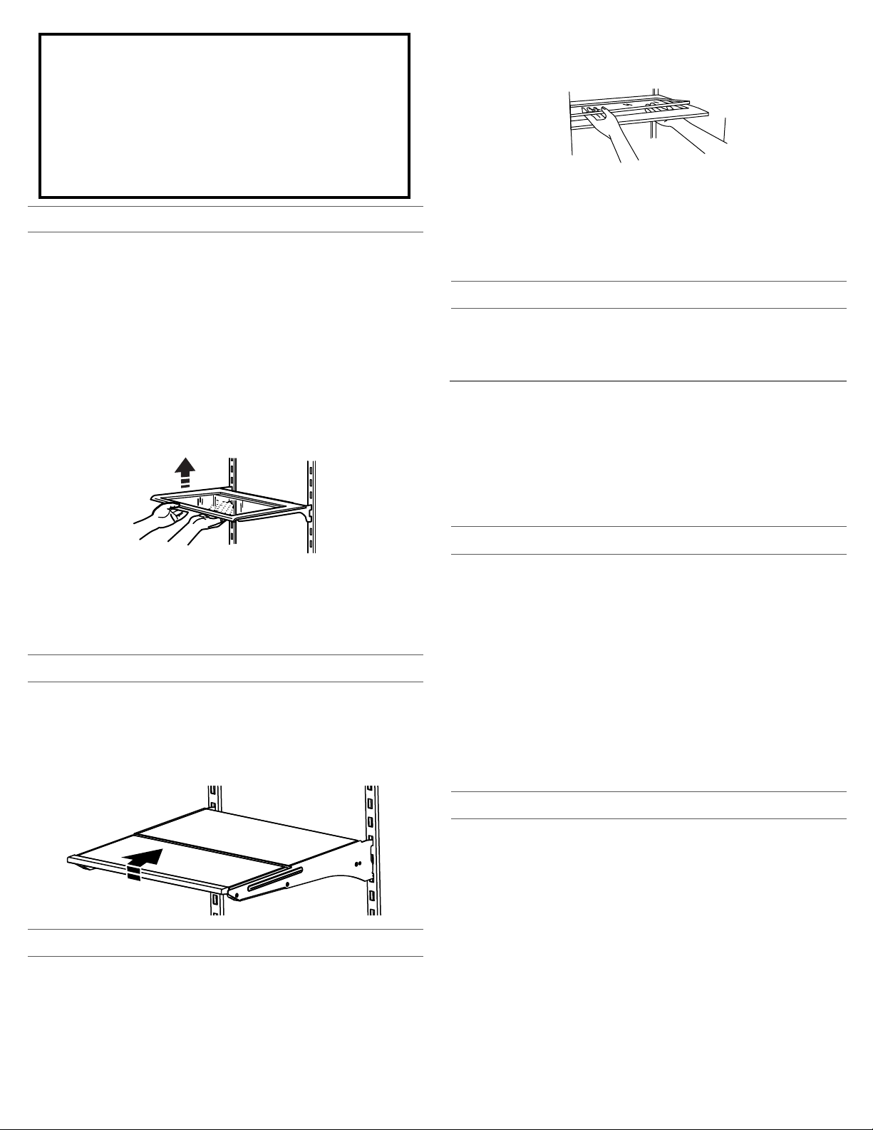
To remove and replace a shelf/shelf frame:
1. Remove the shelf/frame by tilting it up at the front and lifting it out
of the shelf supports.
2. Replace the shelf/frame by guiding the rear shelf hooks into the
shelf supports. Tilt the front of the shelf up until rear shelf hooks
drop into the shelf supports.
3. Lower the front of the shelf and make sure that the shelf is in
position.
2. Holding the glass insert firmly with one hand, press up in center of
glass insert until it rises above the plastic frame. Gently slide the
glass insert forward to remove.
3. Lift the cover frame up and remove it.
To replace crisper(s) cover:
1. Fit back of cover frame into supports on side walls of the
refrigerator and lower the front of the cover frame into place.
2. Slide rear of glass insert into cover frame and lower front into
place.
3. Replace crisper drawers.
Refrigerator Door Bins
The bins on your refrigerator door are adjustable to meet your
individual storage needs.
NOTE: The smallest door bin must be installed in the lowest position
on the refrigerator door.
Water and Ice Dispensers
IMPORTANT:
■ Allow 3 hours for the refrigerator to cool down and chill water.
■ Allow 24 hours to produce the first batch of ice. Discard the first
three batches of ice produced.
■ The dispensing system will not operate when either the refrigerator
door or freezer drawer is open.
Shelves with under-shelf lighting (on some models):
■ The hooks on the rear of the shelf must be fully engaged in the
shelf supports to maintain proper electrical flow.
■ No more than two shelves with under-shelf lighting may be used in
the refrigerator at one time.
Tuck Away Shelf (on some models)
To retract and extend the front section of the shelf:
1. To retract the front-section of the shelf, slightly lift up on the front
edge and push the adjustable portion of the shelf back toward the
rear of the refrigerator.
2. Extend the front of the shelf by pulling the retracted portion of the
shelf outward until it is fully extended.
Crisper Drawers
To remove and replace the drawers:
1. Grasp the handle at the bottom of the drawer and slide the drawer
straight out to the stop. Lift the drawer off the bottom guide.
2. Replace the drawer by placing it on the bottom drawer guide and
pushing it past the drawer stop into position.
To remove the crisper(s) cover:
1. Remove crisper drawers.
Flush the Water System
Air in the water dispensing system can cause the water dispenser to
drip. After connecting the refrigerator to a water source or replacing
the water filter, flush the water system.
Flushing the water dispensing system, forces air from the water line
and filter and prepares the water filter for use. Additional flushing may
be required in some households.
NOTE: As air is cleared from the system water may spurt out of the
dispenser.
1. Using a sturdy container, depress and hold the water dispenser
paddle for 5 seconds.
2. Release the dispenser paddle for 5 seconds. Repeat steps 1 and 2
until water begins to flow.
3. Once water begins to flow, continue depressing and releasing the
dispenser pad (5 seconds on, 5 seconds off) until a total of 3 gal.
(12 L) has been dispensed.
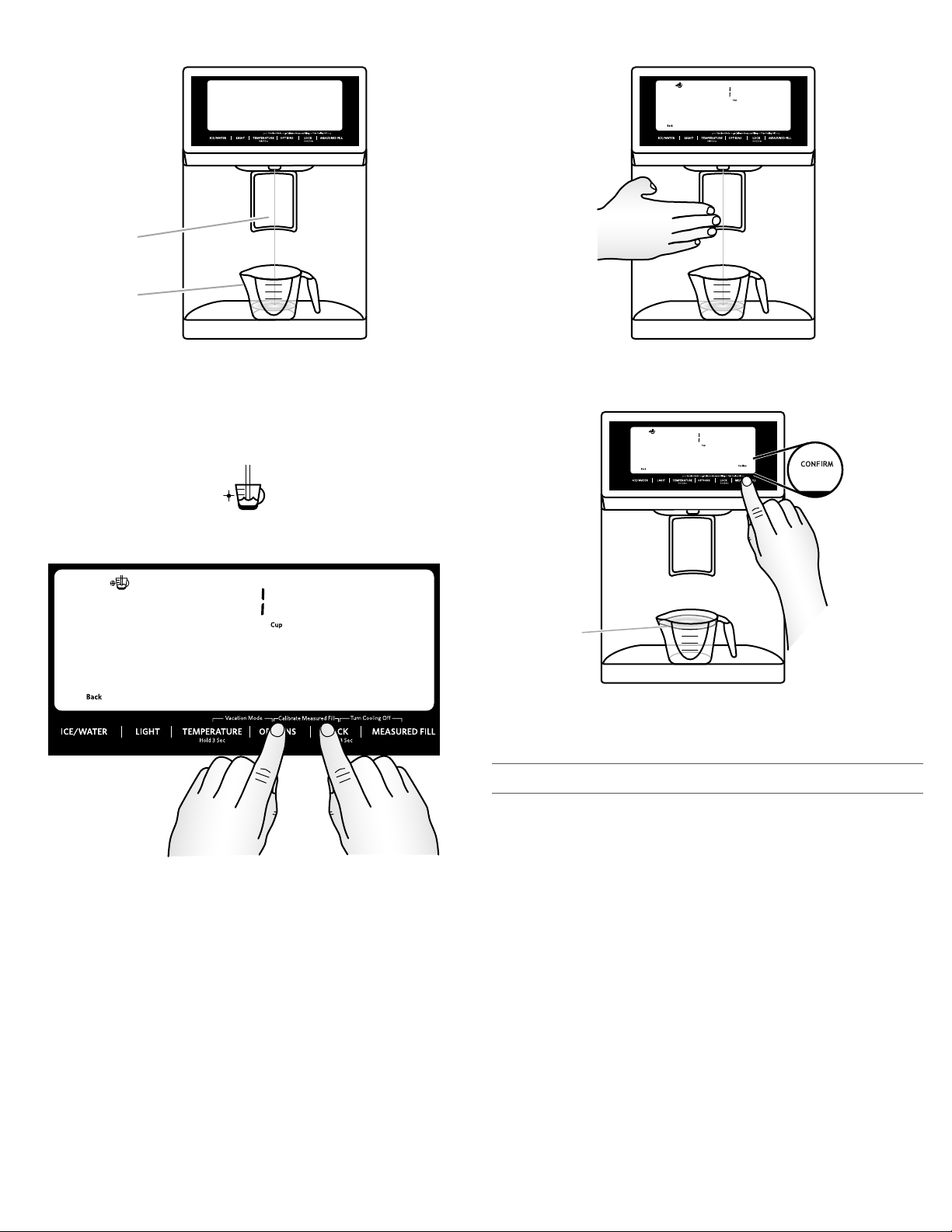
Calibrate Measured Fill
Household water pressure may affect the accuracy of the Measured
Fill feature. So, for optimum performance of your water dispenser, you
must first calibrate Measured Fill.
IMPORTANT:
■ Flush the water system before calibrating Measured Fill.
■ For best results, calibration should be performed when water is not
being used in the house.
1. Place a sturdy measuring cup (1 cup [237 mL] size) on the
dispenser tray centered in front of the water dispenser paddle.
2323
NOTE: Depending on your model, a measuring cup may be
A
B
A
provided.
NOTE: If overfilling or spilling occurs, discard the water and press
ICE/WATER “Back” to restart the calibration process.
A. Water dispenser paddle
B. Measuring cup (1 cup)
2. Press and hold the OPTIONS and LOCK buttons at the same time
for 3 seconds. The words “Back” and “1 Cup” will appear on the
display screen. Also, the Calibrate Measured Fill icon will illuminate
and remain lit while the Measured Fill feature is being calibrated.
NOTE: You may press ICE MODE “Back” at any time to exit
calibration mode. The Calibrate Measured Fill icon will disappear.
4. When 1 cup of water has been correctly dispensed into the
measuring cup, press the MEASURED FILL button under the word
“Confirm” to confirm the calibration.
A. 1 cup of water
5. When Measured Fill calibration has been confirmed the icons will
disappear and the display will return to the home screen.
Dispensing
3. Press and release the dispenser paddle, as needed, to dispense
water to the 1 cup fill line.
2424
Press ICE/WATER to toggle through the following choices in a
continuous loop:
■ Water (default) - Dispenses water
■ Cubed - Dispenses cubed ice.
■ Crushed - Dispenses crushed ice
NOTES:
■ The word “ICE” appears on the display screen when either
crushed or cubed ice is selected.
■ For crushed ice, cubes are crushed before being dispensed.
This may cause a slight delay when dispensing crushed ice.
Noise from the ice crusher is normal, and pieces of ice may
vary in size.
 Loading...