

KitchenAid KESI901PBS, KESA907P, KESV908PSS, KESV908PMT, KESA907PWW Technical Education
...
KAC-38
TECHNICAL EDUCATION
SELF-CLEANING
SLIDE-IN/FREESTANDING
ELECTRIC RANGES
Freestanding Model: KERA807P
Slide-In Models: KESV808P, KESV908P,
KESA907P, & KESI901P
JOB AID 4317354

FORWARD
This KitchenAid Job Aid, “Self-Cleaning Slide-In/Freestanding Electric Ranges,” (Part #4317354),
provides the technician with information on the installation, operation, and service of Self-Cleaning
Slide-In/Freestanding Electric Ranges. It is to be used as a training Job Aid and Service Manual.
For specific information on the model being serviced, refer to the “Use and Care Guide,” or “Wiring
Diagram” provided with the electric range.
The Wiring Diagrams and Strip Circuits used in this Job Aid are typical and should be used for
training purposes only. Always use the Wiring Diagram supplied with the product when servicing
the unit.
GOALS AND OBJECTIVES
The goal of this Job Aid is to provide detailed information that will enable the service technician to
properly diagnose malfunctions and repair KitchenAid Self-Cleaning Slide-In/Freestanding Electric Ranges.
The objectives of this Job Aid are to:
• Understand and follow proper safety precautions.
• Successfully troubleshoot and diagnose malfunctions.
• Successfully perform necessary repairs.
• Successfully return the range to its proper operational status.
WHIRLPOOL CORPORATION assumes no responsibility for any repairs made
on our products by anyone other than Authorized Service Technicians.
Copyright © 2004, Whirlpool Corporation, Benton Harbor, MI 49022
- ii -

TABLE OF CONTENTS
Page
GENERAL............................................................................................................................... 1-1
Safety First......................................................................................................................... 1-1
Model & Serial Number Designations ................................................................................ 1-2
Model & Serial Number Label & Tech Sheet Locations..................................................... 1-3
Specifications..................................................................................................................... 1-4
KitchenAid Electric Range Warranty.................................................................................. 1-6
INSTALLATION INFORMATION ........................................................................................... 2-1
Installation Requirements .................................................................................................. 2-1
Tools And Parts ............................................................................................................. 2-1
Location Requirements .................................................................................................. 2-2
Product Dimensions....................................................................................................... 2-3
Installation Clearances .................................................................................................. 2-4
Electrical Requirements ................................................................................................. 2-5
Countertop Preparation (Slide-In Ranges Only) ............................................................ 2-7
Installation Instructions ...................................................................................................... 2-8
Electrical Connection ..................................................................................................... 2-8
THEORY OF OPERATION ..................................................................................................... 3-1
Convection Bowtie Baffle ................................................................................................... 3-1
COMPONENT ACCESS ......................................................................................................... 4-1
Component Locations ........................................................................................................ 4-1
Removing The EOC Assembly On Slide-In & Freestanding Models,
And The User Interface.................................................................................................. 4-2
Removing An LED Indicator And An Infinite Switch .......................................................... 4-4
Removing The Cooktop Glass ........................................................................................... 4-5
Removing The Control & Cooling Fan Thermal Switches And
The Door Latch Assembly ............................................................................................. 4-6
Removing The Control Power Supply And The Power Supply Transformer ..................... 4-7
Removing An Element & Limiter And The Hot Surface Indicator Assembly ...................... 4-8
Removing The Rear Panel ................................................................................................ 4-9
Removing An Oven Light Socket Assembly .................................................................... 4-10
Removing The Dual Broil Element................................................................................... 4-11
Removing The Oven Temperature Sensor ...................................................................... 4-12
Removing The Convection Element & Fan Motor ........................................................... 4-13
Removing The Cooling Fan ............................................................................................. 4-15
Removing The Oven TOD ............................................................................................... 4-16
Removing The Hidden Bake Element.............................................................................. 4-17
Removing The Warming Drawer Temperature Sensor And Element .............................. 4-19
Removing A Side Panel ................................................................................................... 4-21
Removing & Reinstalling The Oven Door ........................................................................ 4-22
Removing The Oven Door Gasket................................................................................... 4-23
Removing The Decorative Glass And Oven Door Handle,
The Hinges, And The Oven Door Glass ...................................................................... 4-24
- iii -

Page
COMPONENT TESTING ........................................................................................................ 5-1
Infinite (Smart) Switch........................................................................................................ 5-1
Dual & Single Infinite & Warming Drawer Switches
Models: KESV808, KESV908, & KESI901 .................................................................... 5-1
Control & Cooling Fan Thermal Switches .......................................................................... 5-2
Door Latch Assembly......................................................................................................... 5-2
Power Supply Transformer ................................................................................................ 5-3
Oven & Warming Drawer Temperature Sensors ............................................................... 5-3
Elements & Limiters ........................................................................................................... 5-4
Dual Broil Element ............................................................................................................. 5-5
Convection Element........................................................................................................... 5-5
Convection Fan Motor ....................................................................................................... 5-6
Cooling Fan Motor ............................................................................................................. 5-6
Oven TOD.......................................................................................................................... 5-7
Hidden Bake Element ........................................................................................................ 5-7
Warming Drawer Element.................................................................................................. 5-8
DIAGNOSTICS & TROUBLESHOOTING .............................................................................. 6-1
Diagnostics ........................................................................................................................ 6-1
Troubleshooting ................................................................................................................. 6-6
WIRING DIAGRAMS & STRIP CIRCUITS ............................................................................. 7-1
Wiring Diagrams ................................................................................................................ 7-1
Strip Circuits ...................................................................................................................... 7-3
- iv -
GENERAL
SAFETY FIRST
Your safety and the safety of others is very important.
We have provided many important safety messages in this Job Aid and on the appliance. Always
read and obey all safety messages.
This is the safety alert symbol.
This symbol alerts you to hazards that can kill or hurt you and others.
All safety messages will follow the safety alert symbol and either the word
“DANGER” or “WARNING.” These words mean:
You can be killed or seriously injured if you don’t
DANGER
WARNING
All safety messages will tell you what the potential hazard is, tell you how to reduce the chance
of injury, and tell you what can happen if the instructions are not followed.
immediately follow instructions.
You can be killed or seriously injured if you don’t
follow instructions.
1-1

MODEL & SERIAL NUMBER DESIGNATIONS
MODEL NUMBER
MODEL NUMBER K ES V 90 8 P MT 0
PRODUCT GROUP
K = KITCHENAID
PRODUCT IDENTIFICATION
DR = DUAL FUEL RANGE
DS = DUAL FUEL SLIDE-IN RANGE
ER = ELECTRIC STANDARD RANGE
ES = ELECTRIC SLIDE-IN RANGE
GR = GAS STANDARD RANGE
GS = GAS SLIDE-IN RANGE
MERCHANDISING SCHEME
A = ARCHITECT
C = CONTRACT / ADVERTISING
I = STANDARD
K/L = SEARS MODELS
P = COMMERCIAL STYLE
V = VBL PRO LINE STYLE
CAPACITY / SIZE / SERIES / CONFIGURATION
1ST POSITION 2ND POSITION
2 = FS RANGE BACK CONTROL 0 = 30″ WIDE
4 = COMMERCIAL 6 = 36″ WIDE
8 = FS RANGE FRONT CONTROL 8 = 48″ WIDE
9 = SLIDE-IN
FEATURES
0 = CONVENTIONAL OVEN, COIL COOKTOP
1 = CONVENTIONAL OVEN, CERAN OR GAS COOKTOP
2 = CONVENTIONAL OVEN, WARMING DRAWER, GAS COOKTOP
3 = CONVENTIONAL OVEN, AUTO CONVECT, CERAN
OR GAS COOKTOP
4 = CONVECTION OVEN, COIL COOKTOP
5 = CONVECTION OVEN, CERAN COOKTOP
6 = CONVECTION OVEN, GAS COOKTOP W / TRIPLE TIER
7 = CONVECTION OVEN, WARMING DRAWER, CERAN COOKTOP
W / ELECTRONIC KNOB COOKTOP, OR GAS COOKTOP
W / TRIPLE TIER
8 = CONVECTION OVEN, WARMING DRAWER, CERAN COOKTOP
W / ELECTRONIC COOKTOP
YEAR OF INTRODUCTION
P - 2004, R = 2005
COLOR CODE
BL = BLACK, WH = WHITE, BT = BISCUIT, MT = METEORITE
BS = BLACK ON STAINLESS, SS = BRUSHED STAINLESS STEEL
ENGINEERING CHANGE (NUMERIC)
SERIAL NUMBER
SERIAL NUMBER X R 31 73981
MANUFACTURING SITE
X = OXFORD, MS
YEAR OF PRODUCTION
R = 2004
WEEK OF PRODUCTION
31 = 31ST WEEK
PRODUCT SEQUENCE NUMBER
1-2
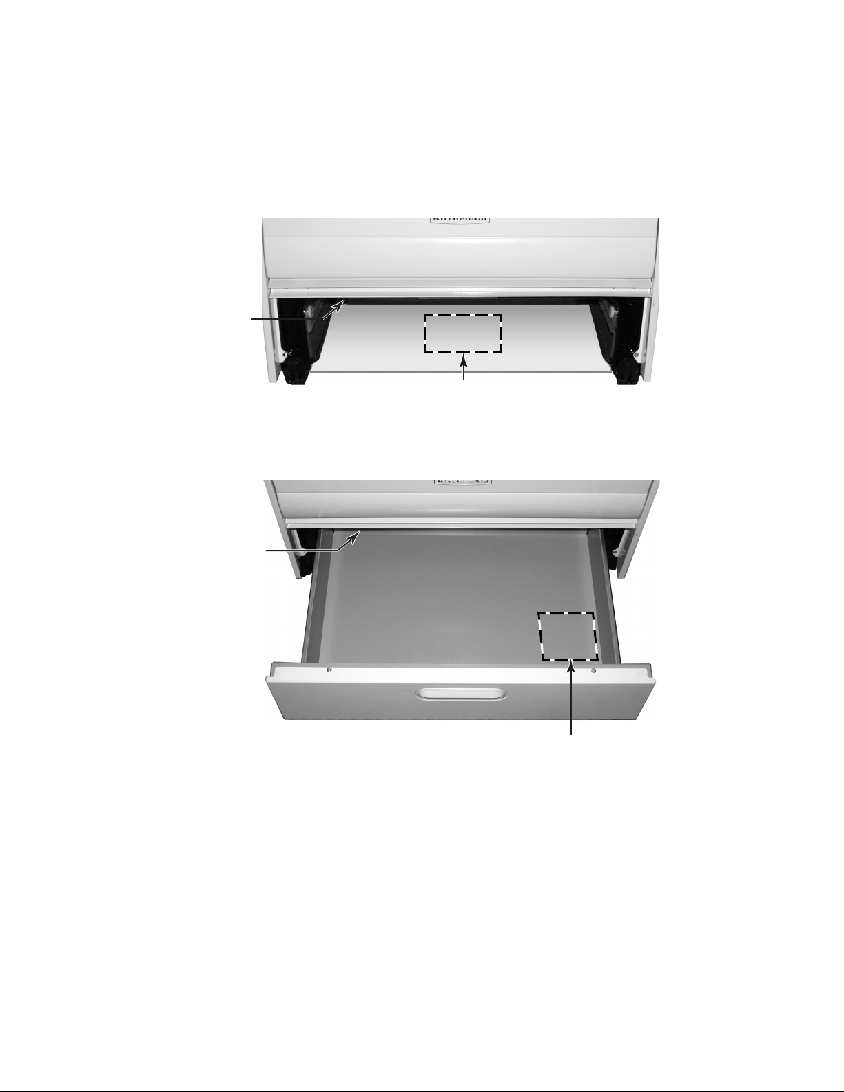
MODEL & SERIAL NUMBER LABEL
& TECH SHEET LOCATIONS
The Model/Serial Number label and Tech Sheet locations are shown below.
Model/Serial
Number Location
(On Chassis Frame)
Tech Sheet Location
Warming Drawer Models Only
(On Chassis Under Drawer)
Model/Serial
Number Location
(On Chassis Frame)
Tech Sheet Location
Storage Drawer Models Only
(On Underside Of Drawer)
1-3

SPECIFICATIONS
Model Number
KESI901P BL, BS, WH KERA807P BB, BL, SS,WW KERK807P BB, BL, SS, WW KESA907P BB, BL, SS, WW KESV908P MT, SS
Model Description
Slide-In
True Convection with Easy Convect
Conversion; Waming Drawer
Freestanding
Slide-In; True Convection with Easy
Convect Conversion; Warming Drawer
Dimensions/Specifications
Exterior Dimensions
Shipping Weight (lbs)
160 180 180 160 160
240 Volts
13.5 14.4 14.4 14.4 13.3
208 Volts
10.1 10.9 10.9 10.9 10
Circuit Amps
40 40 40 40 40
Exterior
Broiler Stop
No No No No No
Cooktop Control Type
Electromechanical Electronic Knobs Electronic Knobs Electronic Knobs Touch Activated Electronics
Cooktop Control #
Knobs - 4, Buttons - 2 Knobs - 4 Knobs - 4 Knobs - 4
Simmer Specialty Switch
Yes - 1 No No No No
Keep Warm Switch
Yes - 1 No No No No
Top Light and Switch
No Yes Yes Yes Yes
Cooktop Lock Out
No No No No Yes
Cooktop Features
Melt & Hold, Keep Warm, & 3
Simmer Levels
Melt & Hold, Keep Warm, & 3
Simmer Levels
Cooktop Material
Ceramic Glass Ceramic Glass Ceramic Glass Ceramic Glass Ceramic Glass
Cooktop Indicator Light
Yes - Red Yes - Red, Yes - Red, Single & Dual Yes - Red, Yes - Red, Single & Dual Yes - Red, Yes - Red, Single & Dual
Yes - Red, Yes - Red, Single, Dual,
Triple
Electric Element Configuration
6", 7", 8", 9.5" 6"/10", 7", 9"/5", 9"/5" 6"/10", 7", 9"/5", 9"/5" 6"/10", 7", 9"/5", 9"/5" 6"/10", 6", 9"/5", 9"/7"/5"
Electric Element Type
Radiant Radiant Radiant Radiant Radiant
Electric RF Output (w@240/208v)
7" 1800W @ 240V 7" 1800W @ 240V 7" 1800W @ 240V 7" 1800W @ 240V 6" 1500W @ 240W
Electric LF Output (w@240/208v)
9"/5" 2500W/1200W @ 240V 9"/5" 2500W/1200W @ 240V 9"/5" 2500W/1200W @ 240V 9"/5" 2500W/1200W @ 240V 9"/7"/5" 2500W/1600W/800W
Electric RR Output (w@240/208v)
8" 2200 W @ 240W 9"/5" 2500W/1200W @ 240V 9"/5" 2500W/1200W @ 240V 9"/5" 2500W/1200W @ 240V 9"/5" 2500W/1000W
Electric LR Output (w@240/208v)
6" 1500W @ 240W 6"/10" 1000W/1800W @ 240W 6"/10" 1000W/1800W @ 240W 6"/10" 1000W/1800W @ 240W 6"/10" 1000W/1800W @ 240W
Electric Keep Warm Burner
6" - 100W All Elements All Elements All Elements All Elements
Electric Simmer Burner Type
Low Simmer Right Front - 450W
All Elements: 3 Simmer Settings,
1 Melt & Hold Setting
All Elements: 3 Simmer Settings,
1 Melt & Hold Setting
Electrtic Simmer Burner-Number
1
208 V Compensation
Yes Yes Yes Yes
Oven Controls
Jabil GOC KitchenAid Premium Jabil GOC KitchenAid Premium Jabil GOC KitchenAid Premium Jabil GOC KitchenAid Premium Jabil GOC KitchenAid Premium
Bake
Yes Yes Yes Yes Yes
Bread Proofing
Yes Yes Yes Yes Yes
Oven Broil
Yes Yes Yes Yes
Closed Door Broil
Yes Yes Yes Yes Yes
Maxi Broil
Yes Yes Yes Yes Yes
Econo Broil
Yes Yes Yes Yes Yes
Convection
True Convection, 3rd Element True Convection, 3rd Element True Convection, 3rd Element True Convection, 3rd Element
Convection Bake
Yes Yes Yes Yes
Convection Broil
Yes Yes Yes Yes
Convection Roast
Yes Yes Yes Yes
Easy Convection Baked Goods
Yes Yes Yes Yes
Easy Convection Meats
Yes Yes Yes Yes
Easy Convection Other Foods
Yes Yes Yes Yes
Sabbath Mode
Yes Yes Yes Yes Yes
Sales Demo
Yes Yes Yes Yes Yes
Temperature Probe
Yes Yes Yes Yes
208 Volt Compensation
Yes Yes Yes Yes Yes
1-4
Model Number
KESI901P BL, BS, WH KERA807P BB, BL, SS,WW KERK807P BB, BL, SS, WW KESA907P BB, BL, SS, WW KESV908P MT, SS
Interior
Main Oven
Cooking System
Standard True Convection True Convection True Convection True Convection
Cleaning System
Self Cleaning - Timed Self Cleaning - Soil Level & Timed Self Cleaning - Soil Level & Timed Self Cleaning - Soil Level & Timed Self Cleaning - Soil Level & Timed
Auto Self Clean Latch
Yes - Motorized Yes - Motorized Yes - Motorized Yes - Motorized Yes - Motorized
Oven Dimensions
Oven Volume (cu ft)
Overall Capacity: 4.2; AHAM Overall Capacity: 3.9; AHAM Overall Capacity: 3.9; AHAM Overall Capacity: 3.9; AHAM Overall Capacity: 3.9; AHAM
Oven Light Number
2 Incandescent 2 Incandescent 2 Incandescent 2 Incandescent 2 Incandescent
Main Electric Oven
Yes Yes Yes Yes Yes
Hidden Bake Element
Yes Yes Yes Yes Yes
Electric Element Output
Bake (W@240/208v)
2000 W 2000 W 2000 W 2000 W 2000 W
Broil (W@240/208v)
Broil Inner Elem (W@240/208v)
1790W 1790W 1790W 1790W 1790W
Broil Outer Elem (W@240/208v)
1450W 1450W 1450W 1450W 1450W
Convection (W@240/208v)
1600W 1600W 1600W 1600W
Oven Lower Panel/ Door
Yes Yes Yes Yes Yes
Warming Drawer
Yes Yes Yes Yes
Warming Drawer Element Wattage
850 W 850 W 850 W 850 W
Accessories
Griddle
Yes - Optional Yes - Optional Yes - Included Yes - Optional Yes - Optional
Griddle Part/Comment
4396096 4396096 9755634 4396096 4396096
Miscellaneous
Installation Instructions Part/Comme
9757446 9757446 9757446 9757446 9757446
Tech Sheet Part/Comment 9757663 9757662 9757662 9757662 9757662
Job Aid Part/Comment 4317354 4317354 4317354 4317354 4317354
Use & Care Guide Part/Comment
9757451 9757451 9757451 9757451 9757451
Agency Approvals
UL UL UL UL UL
Anti-tip Device With Unit
Floor Floor Floor Floor Floor
Warranty
Full
11 months 12 months 12 months 12 months 12 months
Extended
Ceramic Glass Cooking Surface
2nd through 5th year, parts 2nd through 5th year, parts 2nd through 5th year, parts 2nd through 5th year, parts 2nd through 5th year, parts
Electronic Controls
2nd through 5th year, parts 2nd through 5th year, parts 2nd through 5th year, parts 2nd through 5th year, parts 2nd through 5th year, parts
Electrical Elements
2nd through 5th year, parts 2nd through 5th year, parts 2nd through 5th year, parts 2nd through 5th year, parts 2nd through 5th year, parts
Porcelain Liner/Door
1st through 10th year, parts 2nd through 10th year, parts 2nd through 10th year, parts 2nd through 10th year, parts 2nd through 10th year, parts
1-5
KITCHENAID ELECTRIC RANGE WARRANTY
LENGTH OF WARRANTY
FULL ONE YEAR WARRANTY
From Date of Purchase.
SECOND THROUGH FIFTH
YEAR LIMITED WARRANTY
From Date of Purchase.
SECOND THROUGH TENTH
YEAR LIMITED WARRANTY
From Date of Purchase.
KITCHENAID WILL NOT PAY FOR:
A. Service calls to:
1. Correct the installation of the range.
2. Instruct you how to use the range.
3. Replace house fuses or correct house wiring.
B. Repairs when range is used in other than normal, single family household use.
C. Damage resulting from accident, alteration, misuse, abuse, fire, flood, acts of God, improper installation, or
installation not in accordance with local electrical codes.
D. Any labor costs during the limited warranties.
E. Replacement parts or repair labor costs for units operated outside the United States and Canada.
F. Pickup and delivery. Your range is designed to be repaired in the home.
G. Repairs to ceramic glass cooktop if it has not been cared for as recommended in the Use and Care Guide.
H. Repairs to parts or systems resulting from unauthorized modifications made to the appliance.
I. In Canada, travel or transportation expenses to customers who reside in remote areas.
KITCHENAID WILL PAY FOR:
Replacement parts and repair labor costs to correct defects in materials
or workmanship. Service must be provided by a KitchenAid designated
servicing outlet.
Replacement parts for any electric element to correct defects in materials or workmanship. Replacement ceramic glass if breakage is due to
defects in materials or workmanship. Replacement parts for solid state
touch control system to correct defects in materials or workmanship.
Replacement parts for the porcelain oven cavity / inner door if the part
rusts through due to defects in materials or workmanship.
KITCHENAID OR KITCHENAID CANADA DO NOT ASSUME ANY RESPONSIBILITY FOR INCIDENTAL OR
CONSEQUENTIAL DAMAGES. Some states or provinces do not allow the exclusion or limitation of incidental or
consequential damages, so this exclusion or limitation may not apply to you. This warranty gives you specific legal
rights, and you may also have other rights which vary from state-to-state or province-to-province.
Outside the United States and Canada, a different warranty may apply. For details, please contact your
authorized KitchenAid dealer.
If you need service first see the “Troubleshooting” section of the Use and Care Guide. After checking “Troubleshooting,” additional help can be found by checking the “Requesting Assistance or Service” section, or by calling
our Customer Interaction Center telephone numbers, listed below, from anywhere in the U.S.A. or Canada.
KitchenAid: 1-800-422-1230
Canadian Residents call: 1-800-807-6777
1-6
INSTALLATION INFORMATION
INSTALLATION REQUIREMENTS
TOOLS AND PARTS
Assemble the required tools and parts before
starting installation. Read and follow the safety
instructions provided with any tools listed here.
Tools Needed
• Tape measure
• Flat-blade screwdriver
• Level
• Hammer
• Hand or electric drill
• Channel lock pliers
• Marker or pencil
• Masking tape
• 3/8″ drive rachet
• 1/4″ nut driver
• 5/16″ nut driver
• 1/8″ (3.2 mm) drill bit (for wood floors)
• 3/16″ (4.8 mm) carbide-tipped masonry drill
bit (for concrete/ceramic floors)
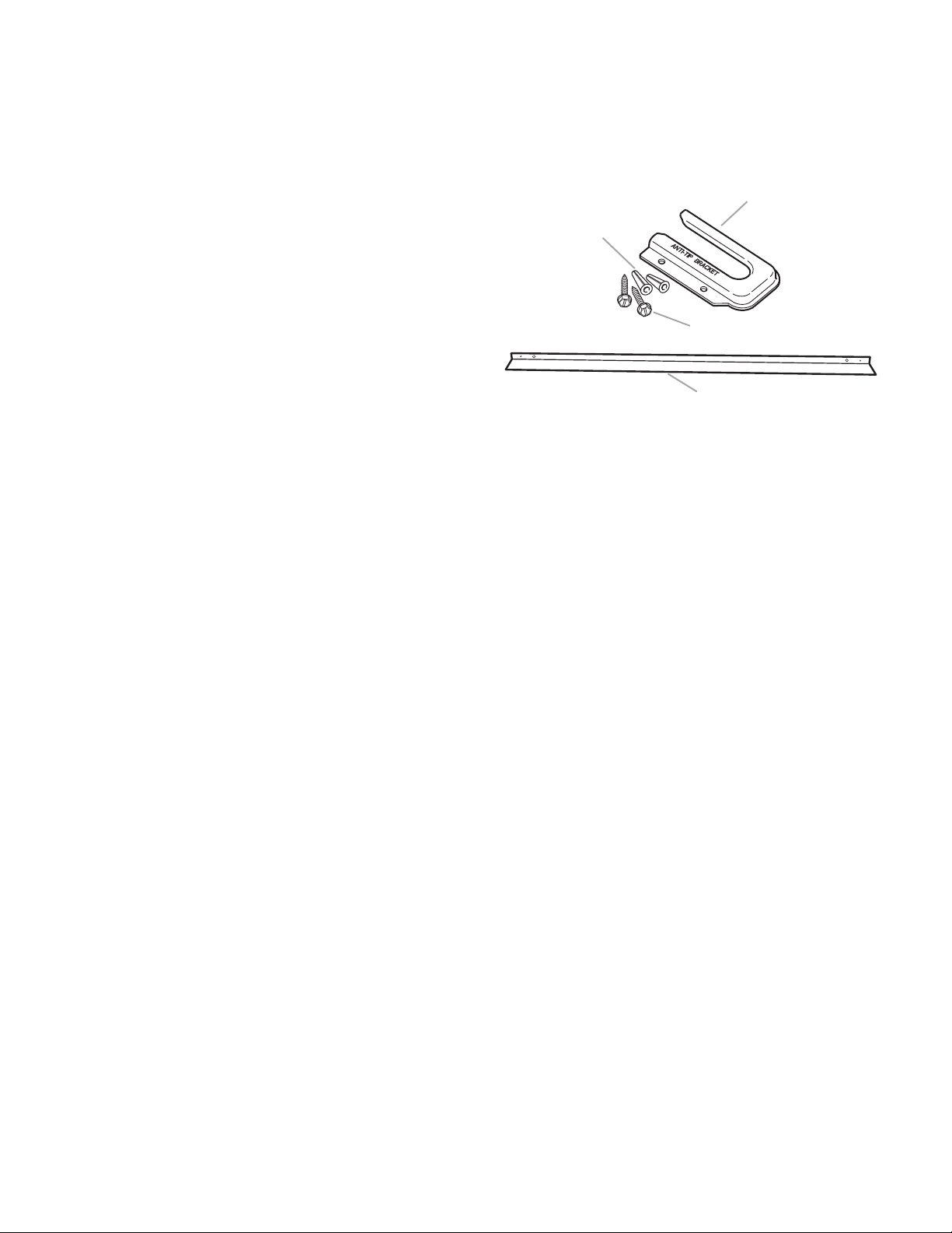
Parts Supplied
B
C
D
A. Anti-tip bracket
B. Plastic anchors (2)
C. #10 x 1/2″ screws (2)
D. Rear spacer cover for slide-in models
(supplied on some models)*
* To order, contact your dealer or refer to the “Assis-
tance or Service” section of the Use and Care Guide.
Request Part #9757784WH (White), #9757784BT
(Biscuit), #9757784BL (Black), #9757784MT (Mete-
orite), or #9757784SS (Stainless Steel).
A
Check that all parts are included.
• Brackets must be securely mounted to
subfloor. Thickness of flooring may require
longer screws to anchor bracket to subfloor.
Longer screws are available from your local
hardware store.
Parts Needed
Check local codes. Check existing electrical
supply (see “Electrical Requirements” on page
2-5).
All electrical connections should be made by a
licensed, qualified electrical installer.
2-1

LOCATION REQUIREMENTS
IMPORTANT: Observe all governing codes
and ordinances. Failure to meet codes and
ordinances could lead to fire or electrical shock.
• It is the installer’s responsibility to comply
with installation clearances specified on the
model/serial rating plate. The model/serial
rating plate is located on the oven frame
behind the storage drawer panel.
• The range should be located for convenient
use in the kitchen.
• To eliminate the risk of burns or fire by
reaching over heated surface units, cabinet
storage space located above the surface
units should be avoided. If cabinet storage is
to be provided, the risk can be reduced by
installing a range hood that projects horizontally a minimum of 5″ (12.7 cm) beyond the
bottom of the cabinets.
• Cabinet opening dimensions that are shown
must be used. Given dimensions are minimum clearances.
• The floor anti-tip bracket must be installed.
To install the anti-tip bracket shipped with
the range, see the Installation Instructions
provided with the range.
Mobile Home - Additional Installation Requirements
The installation of this range must conform to
the Manufactured Home Construction and
Safety Standard, Title 24 CFR, Part 3280 (formerly the Federal Standard for Mobile Home
Construction and Safety, Title 24, HUD Part
280). When such standard is not applicable,
use the Standard for Manufactured Home Installations, ANSI A225.1/NFPA 501A or with
local codes.
In Canada, the installation of this range must
conform with the current standards CAN/CSAA240-latest edition, or local codes.
Mobile home installations require:
• When this range is installed in a mobile
home, it must be secured to the floor during
transit. Any method of securing the range is
adequate as long as it conforms to the standards listed above.
• Four-wire power supply cord or cable must
be used in a mobile home installation. The
appliance wiring will need to be revised (see
“Electrical Connection” on page 2-5)
• A grounded electrical supply is required (see
“Electrical Requirements” on page 2-5).
2-2
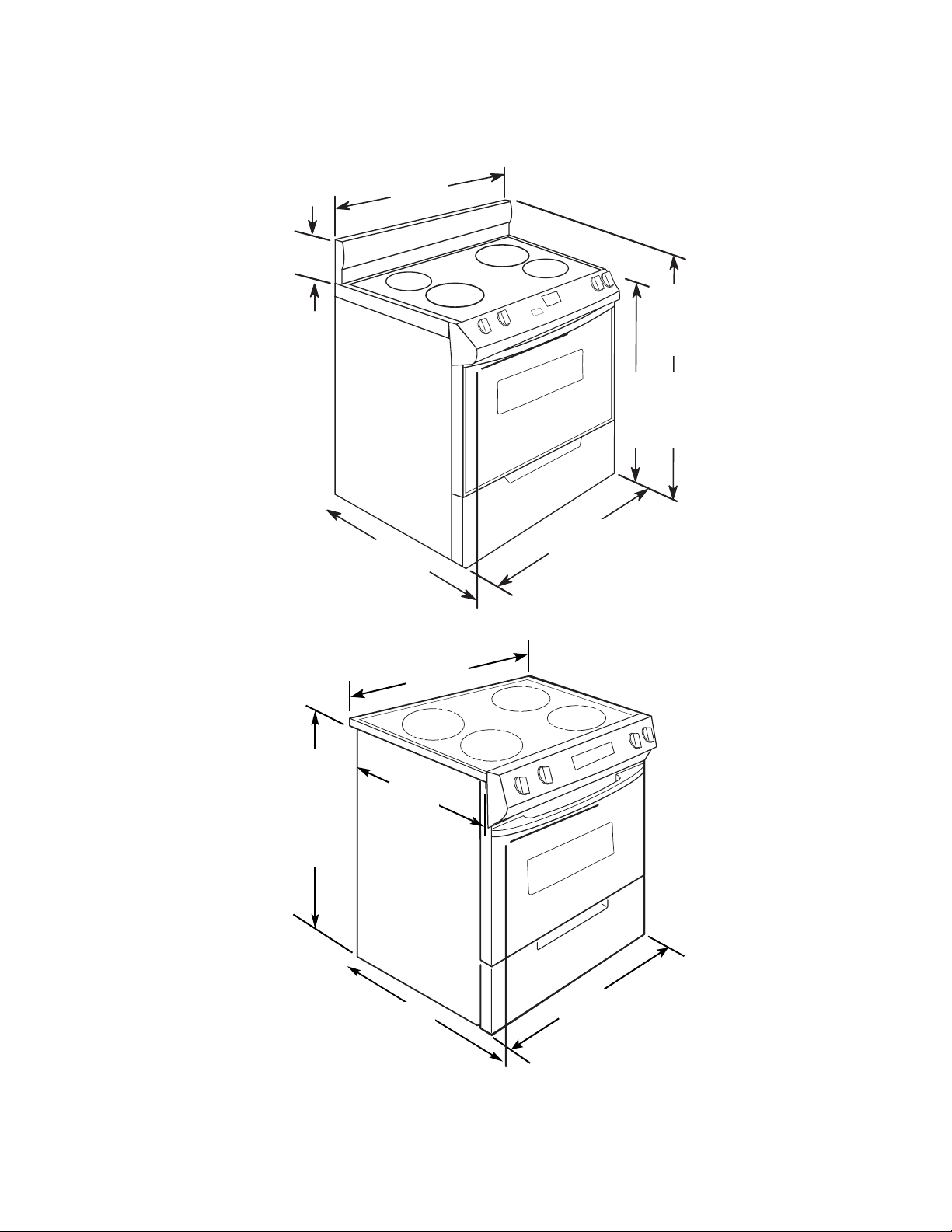
PRODUCT DIMENSIONS
Freestanding Range
7-7/8"
(20 cm)
30"
(76.2 cm)
*27"
(68.6 cm)
to handle
43-7/8"
(111.4 cm)
overall
height
36" (91.4 cm)
cooktop height
with leveling
legs lowered
1-1/2 turns
30"
(76.2 cm)
Slide-In Range
35-5/8"
(90.5 cm)
cooktop height
with leveling
legs lowered
1-1/2
turns
30-11/16"
(77.9 cm)
23-1/2"
(59.8 cm)
* 27"
(68.6 cm)
to handle
30"
(76.2 cm)
* When installed in a 24″ (61 cm) base cabinet with 25″ (63.5 cm) countertop; front of oven door protrudes 1-7/8″
(4.8 cm) beyond 24″ (61 cm) base cabinet.
2-3
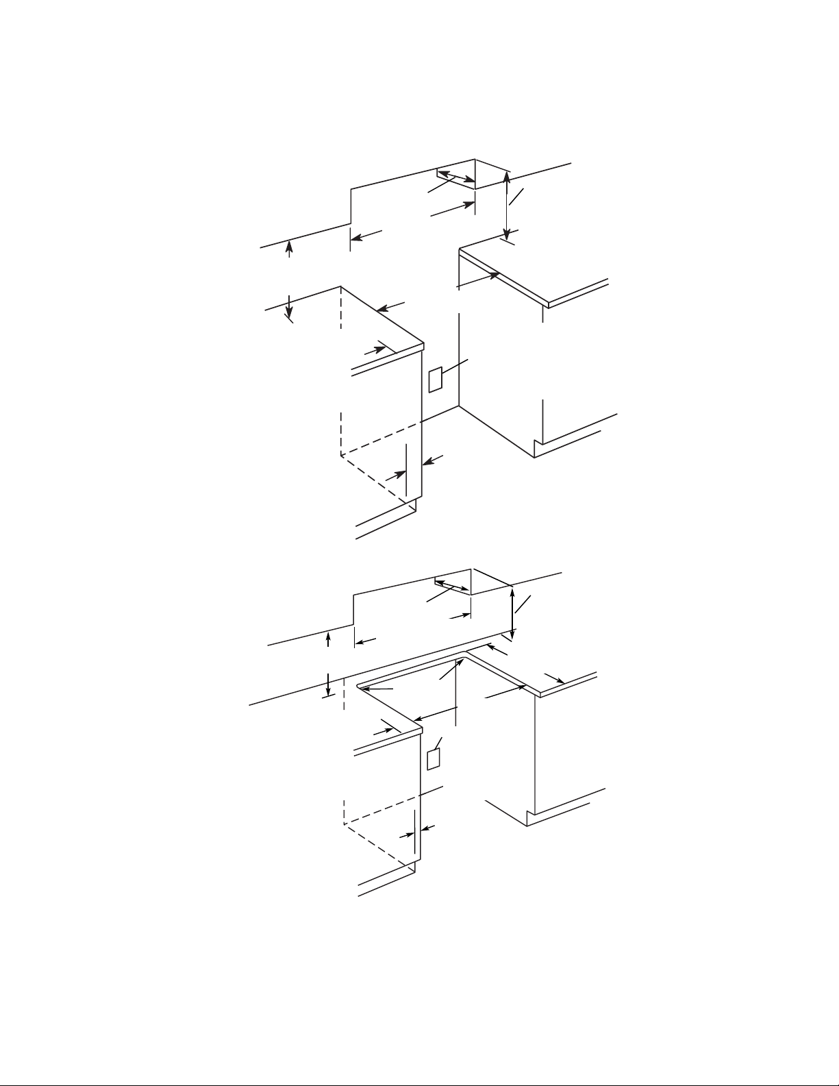
INSTALLATION CLEARANCES
Cabinet opening dimensions shown are for
25,″ (64 cm) countertop depth, 24″ (61 cm)
Freestanding Range
13" (33 cm) max.
upper cabinet depth
18" (45.7 cm)
upper cabinet
to countertop
4" (10.2 cm)
min. clearance
from both sides
of range to side
wall or other
combustible
material.
base cabinet depth and 36″ (91.4 cm)
countertop height.
For minimum
clearance to
the top of the
30" (76.2 cm) min.
opening width
30" (76.2 cm) min.
opening width
Junction box 8" (20.3 cm) to
22" (55.9 cm) from
either cabinet,
7" (17.8 cm) max.
from door.
7/8" (2.2 cm)
min. required
between cutout
and cabinet
door or hinge.
cooktop, see
NOTE.
13" (33 cm)
Slide-In Range
18" (45.7 cm)
upper cabinet to
countertop
4" (10.2 cm) min.
clearance from
both sides of
range to side wall
or other combustible
material between
upper cabinet and
countertop.
upper cabinet depth
30" (76.2 cm)
opening width
NOTE: 24″ (61 cm) minimum when bottom of
wood or metal cabinet is protected by not less
than 1/4″ (0.64 cm) flame retardant millboard
covered with not less than No. 28 MSG sheet
steel, 0.015″ (0.4 mm) stainless steel, 0.024″
For minimum
clearance to
the top of the
cooktop, see
NOTE.
" (57.8 cm)
22-3/4
opening depth
1/4" (6.2 cm)
radius both
corners
30" (76.2 cm)
opening width
Junction box 8" (20.3 cm) to
22" (55.9 cm) from
either cabinet,
7" (17.8 cm) max.
from floor.
7/8" (2.2 cm) min.
required between
cutout and cabinet
door or hinge.
(0.6 mm) aluminum, or 0.020″ (0.5 mm) copper.
30″ (76.2 cm) minimum clearance between the
top of the cooking platform and the bottom of an
unprotected wood or metal cabinet.
2-4

ELECTRICAL REQUIREMENTS
If codes permit and a separate ground wire is
used, it is recommended that a qualified electrical installer determine that the ground path
and wire gauge are in accordance with local
codes.
If codes permit and a separate ground wire is
used, it is recommended that a qualified electrician determine that the ground path is adequate.
Do not use an extension cord.
Be sure that the electrical connection and wire
size are adequate and in conformance with the
National Electrical Code, ANSI/NFPA 70-latest edition and all local codes and ordinances.
A copy of the above code standards can be
obtained from: National Fire Protection Association, One Batterymarch Park, Quincy, MA
02269.
ELECTRICAL CONNECTION
To properly install your range, you must determine the type of electrical connection you will
be using and follow the instructions provided
for it here.
• Range must be connected to the proper
electrical voltage and frequency as specified
on the model/serial number rating plate.
(The model/serial number rating plate is
located on the oven frame behind the storage drawer panel.)
• When a 4-wire or 3-wire, single phase 120/
240-volt, 60 Hz, AC-only electrical supply is
available, a 50 amp maximum circuit protection is required (or, if specified on the model/
serial rating plate, when a 4-wire or 3-wire
single phase 120/208-volt 60 Hz, AC-only
electrical supply is available, a 40 amp maximum circuit protection is required), fused on
both sides of the line.
• The range can be connected directly to the
fused disconnect (or circuit breaker box)
through flexible, armored or nonmetallic
sheathed, copper or aluminum cable.
• Allow 2 to 3 ft. of slack in the line so that the
range can be moved if servicing is ever
necessary.
• A UL listed conduit connector must be provided at each end of the power supply cable
(at the range and at the junction box).
• Wire sizes and connections must conform
with the rating of the range (40 amps).
• The wiring diagram is located on the underside of the storage drawer or below the
warming drawer in a clear plastic bag.
If connecting to a 4-wire system:
This range is manufactured with the ground
connected to the cabinet. The ground must be
revised so the green grounding wire of the 4wire power supply cord is connected to the
cabinet.
Grounding through the neutral conductor is
prohibited for new branch-circuit installations
(1996 NEC); mobile homes; and recreational
vehicles, or an area where local codes prohibit
grounding through the neutral conductor.
When a 4-wire receptacle of NEMA Type 1450R is used, a matching UL listed, 4-wire, 250volt, 40 amp, range power supply cord (pigtail)
must be used. This cord contains 4 copper
conductors with ring terminals or open-end
spade terminals with upturned ends, terminating in a NEMA Type 14-50P plug on the supply
end.
The fourth (grounding) conductor must be identified by a green or green/yellow cover and the
neutral conductor by a white cover.
• A time-delay fuse or circuit breaker is recommended.
2-5

The cord should be Type SRD or SRDT with a
UL listed strain relief and be at least 4 ft.
(1.22m) long.
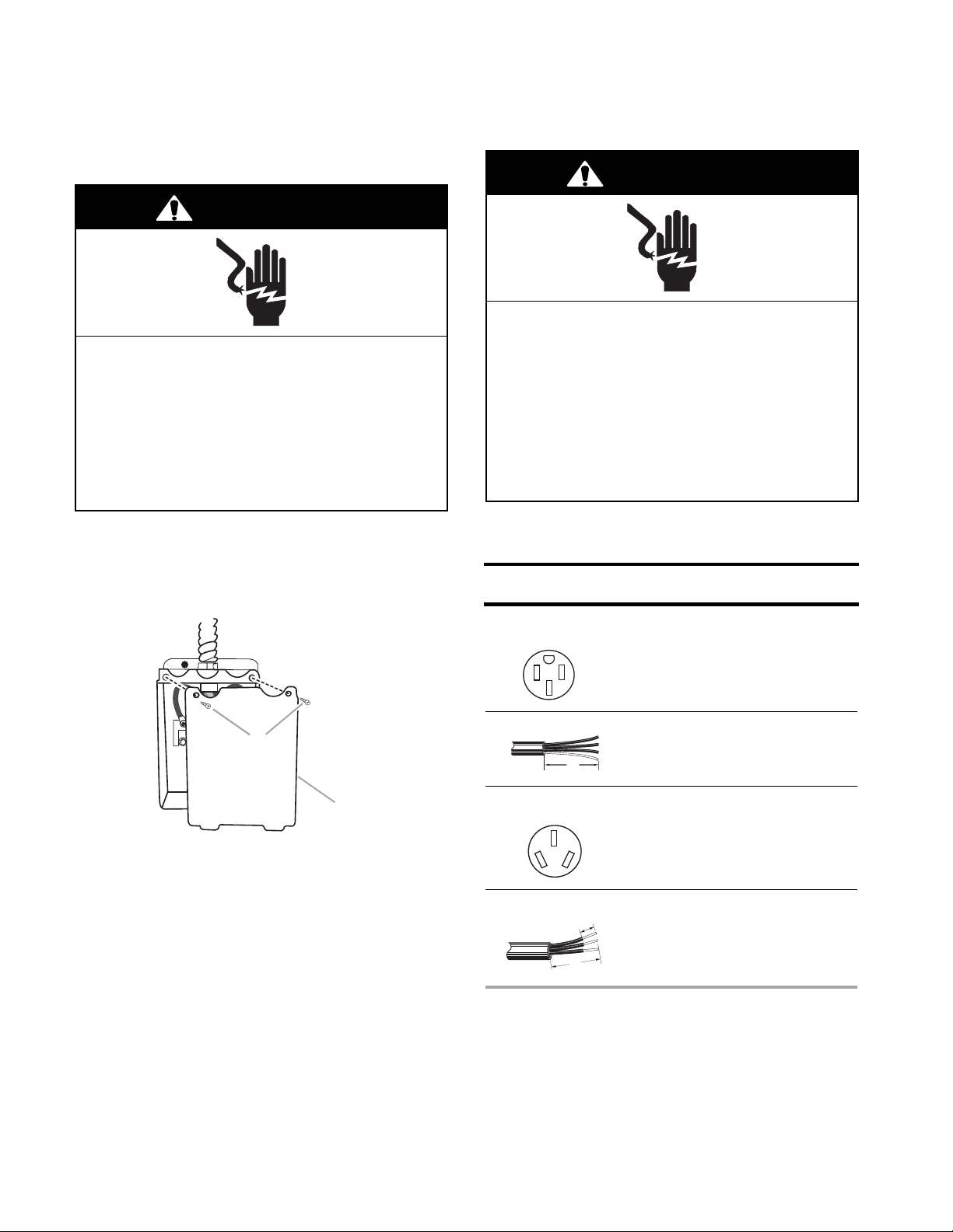
4-Wire Receptacle (14-50R)
The minimum conductor sizes for the copper
4-wire power cord are:
40 amp circuit
2 No.-8 conductors
1 No.-10 white neutral
1 No.-8 green grounding
If connecting to a 3-wire system:
Local codes may permit the use of a UL listed,
3-wire, 250-volt, 40 amp range power supply
cord (pigtail). This cord contains 3 copper
conductors with ring terminals or open-end
spade terminals with upturned ends, terminating in a NEMA Type 10-50P plug on the supply
end. Connectors on the appliance end must be
provided at the point the power supply cord
enters the appliance. This uses a 3-wire receptacle of NEMA Type 10-50R.
3-Wire Receptacle (10-50R)
2-6
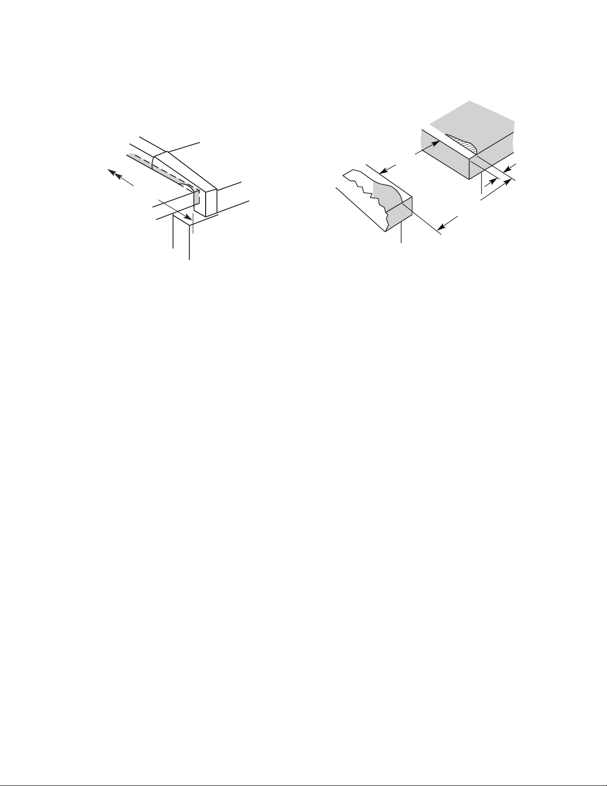
COUNTERTOP PREPARATION
(SLIDE-IN RANGES ONLY)
The cooktop sides of the slide-in range fit over
the cutout edge of the countertop.
Tile countertops may need the trim cut back
3/8″ (1.0 cm) from each front corner, and/or
have the rounded edge flattened.
30"
(76.2 cm)
3/8"
(1.0 cm)
22-3/4"
(57.8 cm)
If you have a square finish (flat) countertop,
and the opening width is 30″ (76.2 cm), no
countertop preparation is required.
Formed front-edged countertops must have
the molded edge shaved flat 3/8″ (1.0 cm) from
each front corner of the opening.
30-3/4"
(78.1 cm)
If the countertop opening width is greater than
30″ (76.2 cm), adjust the 3/8″ (1.0 cm) dimension.
The countertop must be level. Place a level on
the countertop, first side-to-side; then front-toback. If the countertop is not level, the range
will not be level. The oven must be level for
satisfactory baking performance.
2-7
INSTALLATION INSTRUCTIONS
If your home has: And you will be
connecting to:
Go to Section:
4-wire receptacle
(NEMA type 14-50R)
A UL listed,
250-volt
minimum,
40 amp, range
power supply
cord
4-wire connection:
Power supply cord
4-wire direct A fused
disconnect or
circuit breaker
box
4-wire connection:
Direct wire
3-wire receptacle
(NEMA type 10-50R)
A UL listed,
250-volt
minimum,
40 amp, range
power supply
cord
3-wire connection:
3-wire connection:
Power supply cord
3-wire direct A fused
disconnect or
circuit breaker
box
Direct wire
5"
(12.7 cm)
3"
(7.6 cm)
1"
(2.5 cm)
ELECTRICAL CONNECTION
Power Supply Cord
WARNING
Electrical Shock Hazard
Disconnect power before servicing.
Use a new 40 amp power supply cord.
Plug into a grounded outlet.
Failure to follow these instructions can
result in death, fire, or electrical shock.
1. Disconnect power.
2. Remove the hold-down screws and terminal block cover from the back of the range.
Direct Wire
WARNING
Electrical Shock Hazard
Disconnect power before servicing.
Use 8 gauge copper or 6 gauge
aluminum wire.
Electrically ground range.
Failure to follow these instructions can
result in death, fire, or electrical shock.
Electrical Connection Options
3. Complete installation following instructions
A. Hold-down screws
B. Terminal block cover
for your type of electrical connection:
4-wire (recommended)
3-wire (if 4-wire is not available)
A
B
2-8
Power Supply Cord Installation
A. Ground-link screw
B. Cup washer
C. Ground-link bent away from range
A
C
B
WARNING: Improper connection of the equipment-grounding conductor can result in a risk
of electric shock. Check with a qualified electrician or service technician if you are in doubt as
to whether the appliance is properly grounded.
Do not modify the power supply cord plug. If it
will not fit the outlet, have a proper outlet
installed by a qualified electrician.
This range is manufactured with the neutral
terminal connected to the cabinet. Use a 3wire, UL listed, 40 amp power supply cord
(pigtail); or if local codes do not permit ground
through the neutral, use a 4-wire power supply
cord rated at 250-volts, 40 amps and investigated for use with ranges.
1. Remove the knockout for the 40 amp
power supply cord.
4. Connect the terminals (ring-type or spade
with upturned ends) on the end of the
power cord to the power supply.
5. Complete electrical connection according
to your type electrical supply (4-wire or
3-wire electrical connection).
4-wire connection: Power supply cord
Use this method for:
• New branch-circuit installations (1996 NEC)
• Mobile homes
• Recreational vehicles
• In an area where local codes prohibit ground-
ing through the neutral
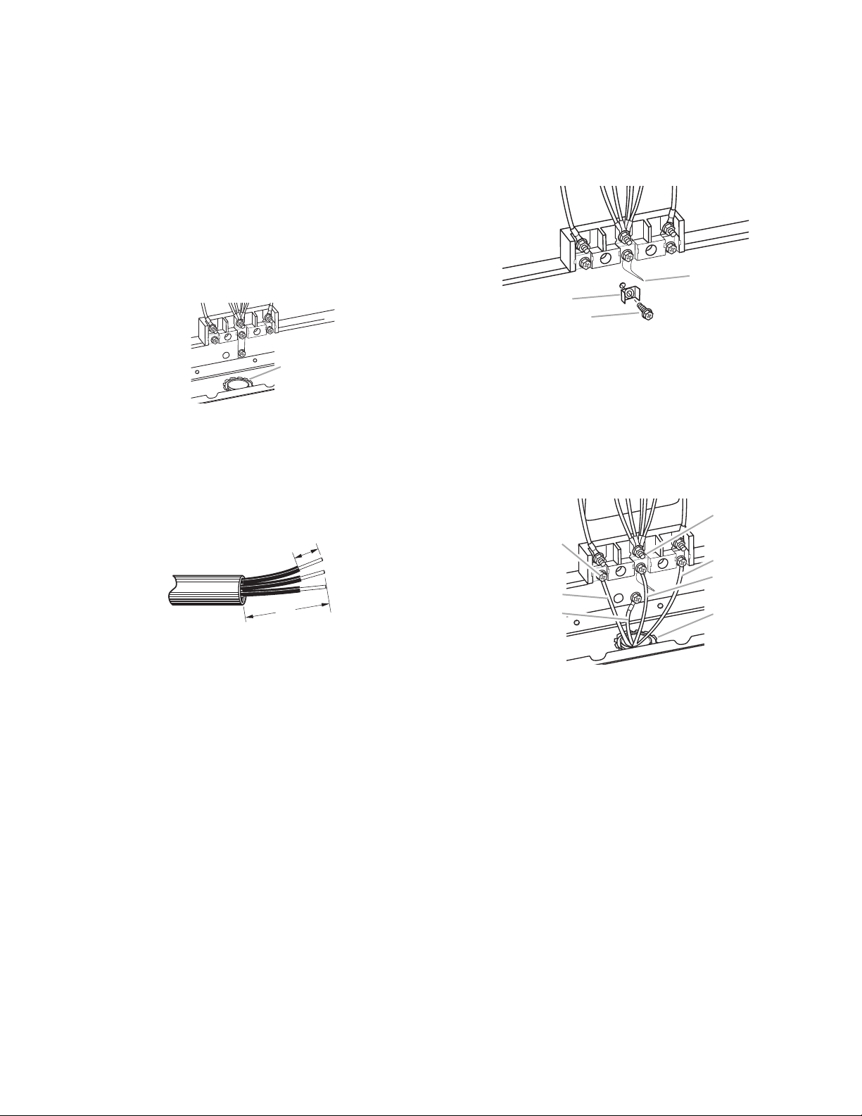
1. Remove the ground-link screw from the
range frame. Save the ground link screw
and cup washer. Bend the ground-link
away from the range so that it does not
contact the range.
A
A. Remove knockout for 40 amp power cord
and UL listed strain relief
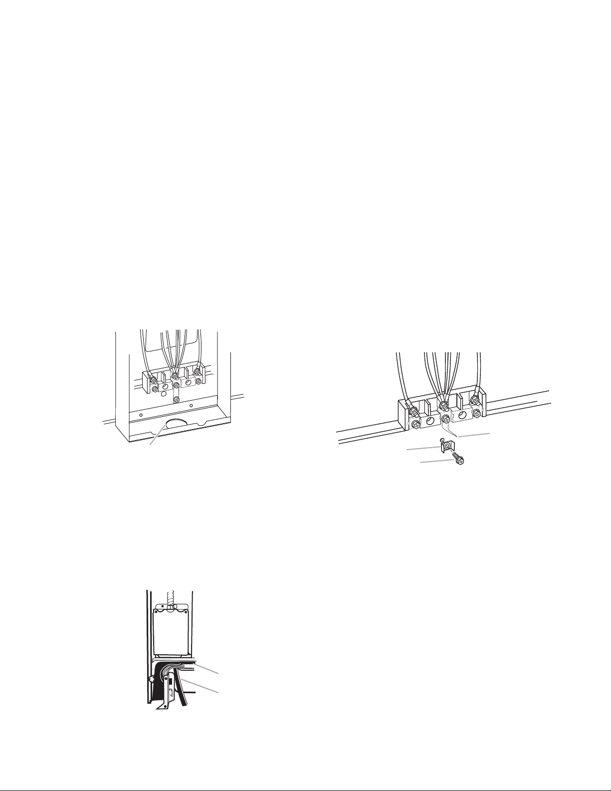
2. Assemble a UL listed strain relief in the
opening.
3. Feed the power supply cord behind the
black horizontal crossbrace and through
the strain relief, allowing enough slack to
easily attach the wiring to the terminal
block.
A
B
A. Black horizontal cross brace
B. Power supply cord
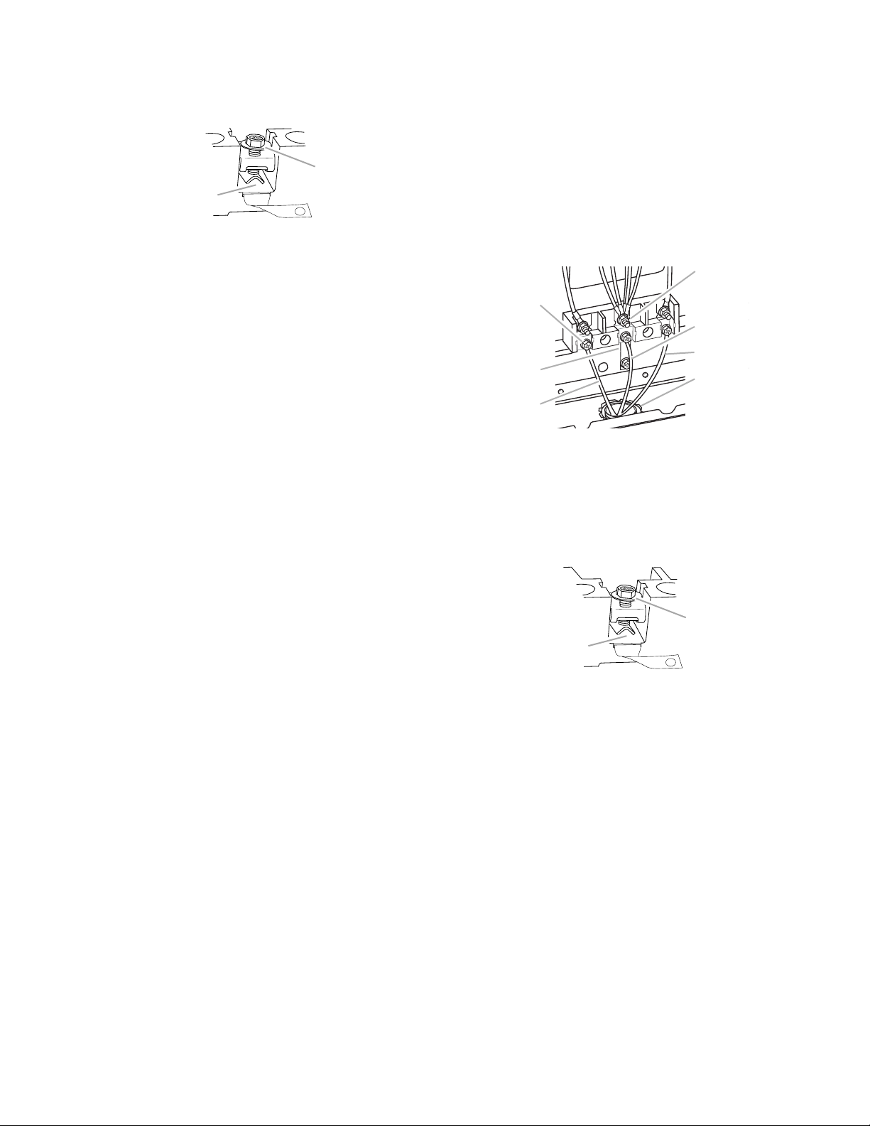
2. Connect the green ground wire from the
power supply cord to the range using the
ground-link screw and cup washer. The
ground wire must be attached first and
must not contact any other terminal.
2-9
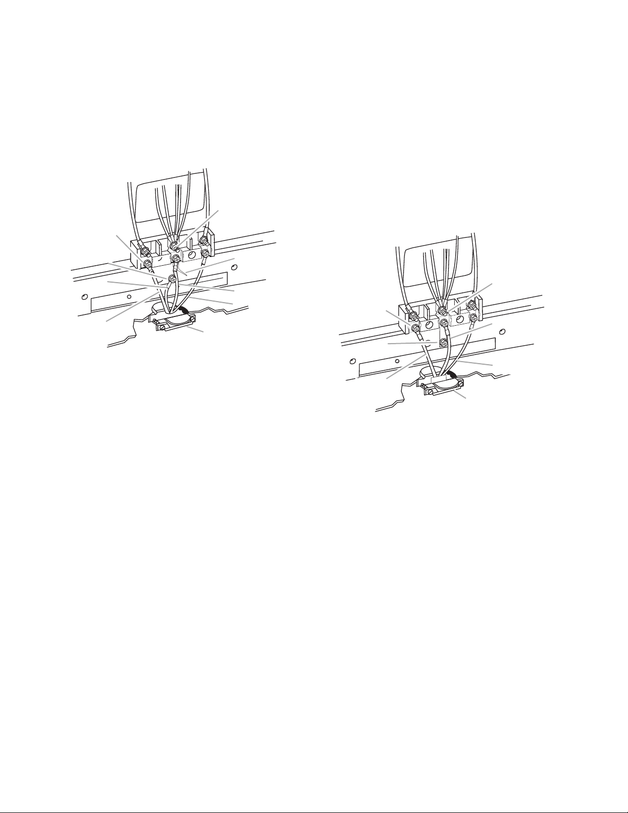
3. Use a 1/4″ nut driver and remove the hex
washer head screws from the terminal
blocks.
4. Connect the neutral (center) wire to the
center terminal connector using one of the
hex washer head screws. Securely tighten
screw for proper electrical connection.
E
D
3-wire connection: Power supply cord
Use this method only if local codes permit
connecting cabinet-ground conductor to neutral wire of power supply cord.
1. Use a 1/4″ nut driver and remove the hex
washer head screws from the aluminum
terminal blocks.
2. Connect the neutral (center) wire to the
center terminal connector using one of the
hex washer head screws. Securely tighten
screw for proper electrical connection.
C
B
A
A. Line 1
B. Green ground wire
C. Ground-link screw
D. Hex washer head screw
E.Silver-colored terminal
block screw
I
F. Ground-link
G. Neutral (center) wire
H. Line 2
I. UL listed strain relief and
40 amp range power
supply cord
F
G
H
5. Connect the other 2 wires (lines 1 and 2)
to the outer aluminum terminal blocks.
6. Securely tighten screws for proper electrical connection.
7. Tighten strain relief screws.
8. Replace terminal block cover.
9. Plug in range or reconnect power.
D
C
E
B
F
A
G
A. Line 1
B. Ground-link
C. Hex washer head screw
D. Silver-colored terminal
block screw
E. Neutral (center) wire
F. Line 2
G. UL listed strain relief
and 40 amp range power
supply cord
3. Connect the other 2 wires (lines 1 and 2)
to the outer terminal screws on the terminal block.
4. Tighten strain relief screws.
5. Replace terminal block cover.
6. Plug in range or reconnect power.
2-10
Direct Wire Installation: Copper or Aluminum Wire
This range may be connected directly to the
fuse disconnect or circuit breaker box. Depending on your electrical supply, make the
required 3-wire or 4-wire connection.
1. Remove the knockout as needed for the
conduit connection.
2. Assemble a UL listed conduit connector in
the opening.
A
A. UL listed conduit connector
3. Strip outer covering back 3″ (7.6 cm) to
expose wires. Strip the insulation back 1″
(2.5 cm) from the end of each wire.
1"
(2.5 cm)
3"
(7.6 cm)
1. Remove the ground-link screw from the
range frame. Save the ground-link screw
and cup washer. Bend the ground-link
away from the range so that it does not
contact the range.
C
B
A
A. Ground-link screw
B. Cup washer
C. Ground-link bent away from range
2. Connect the bare ground wire to the range
using the ground-link screw and cup
washer. The ground wire must be attached
first and must not contact any other terminal.
D
C
E
F
B
A
G
4. Allow enough slack in the wire to easily
attach the wiring terminal block.
5. Complete electrical connection according
to your type electrical supply (4-wire or 3wire electrical connection).
4-wire connection: Direct wire
Use this method for:
• New branch-circuit installations (1996 NEC)
• Mobile homes
• Recreational vehicles
• In an area where local codes prohibit ground-
ing through the neutral
A. Bare wire from power
supply cable
B. Line 1
C. Hex washer head screw
D. Silver-colored terminal
block screw
E.Line 2
F. Neutral (white) wire
G. UL listed conduit
connector and power
supply cable
3. Loosen (do not remove) the hex washer
head screw and insert the neutral (white)
wire under the screw clamp at the bottom
of the center position terminal connector.
2-11
4. Insert the other 2 wires (lines 1 and 2)
under the other 2 screw clamps.
B
A
A. Insert wire under screw clamp
B. Hex washer head screw
3-wire connection: Direct wire
Use this method only if local codes permit
connecting ground conductor to neutral supply
wire.
1. Loosen (do not remove) the hex washer
head screws and insert the neutral (white)
wire under the screw clamp at the bottom
of the center position terminal connector.
D
5. Securely tighten the hex washer head
screws to 90 in.2/lbs minimum torque to
make proper electrical connection.
6. Tighten the locking ring of the conduit
connector.
7. Replace the terminal block cover.
C
E
F
B
A
A. Line 1
B. Ground-link
C. Hex washer head screw
D. Silver-colored terminal
block screw
E. Neutral (white) wire
F. Line 2
G. UL listed conduit
connector and power
supply cable
G
2. Insert the other 2 wires (lines 1 and 2)
under the other 2 screw clamps.
B
A
A. Insert wire under screw clamp
B. Hex washer head screw
3. Securely tighten the hex washer head
screws to 90 in.2/lbs minimum torque to
make a proper electrical connection.
4. Tighten the locking ring of the conduit
connector.
5. Replace the terminal block cover.
2-12
THEORY OF OPERATION
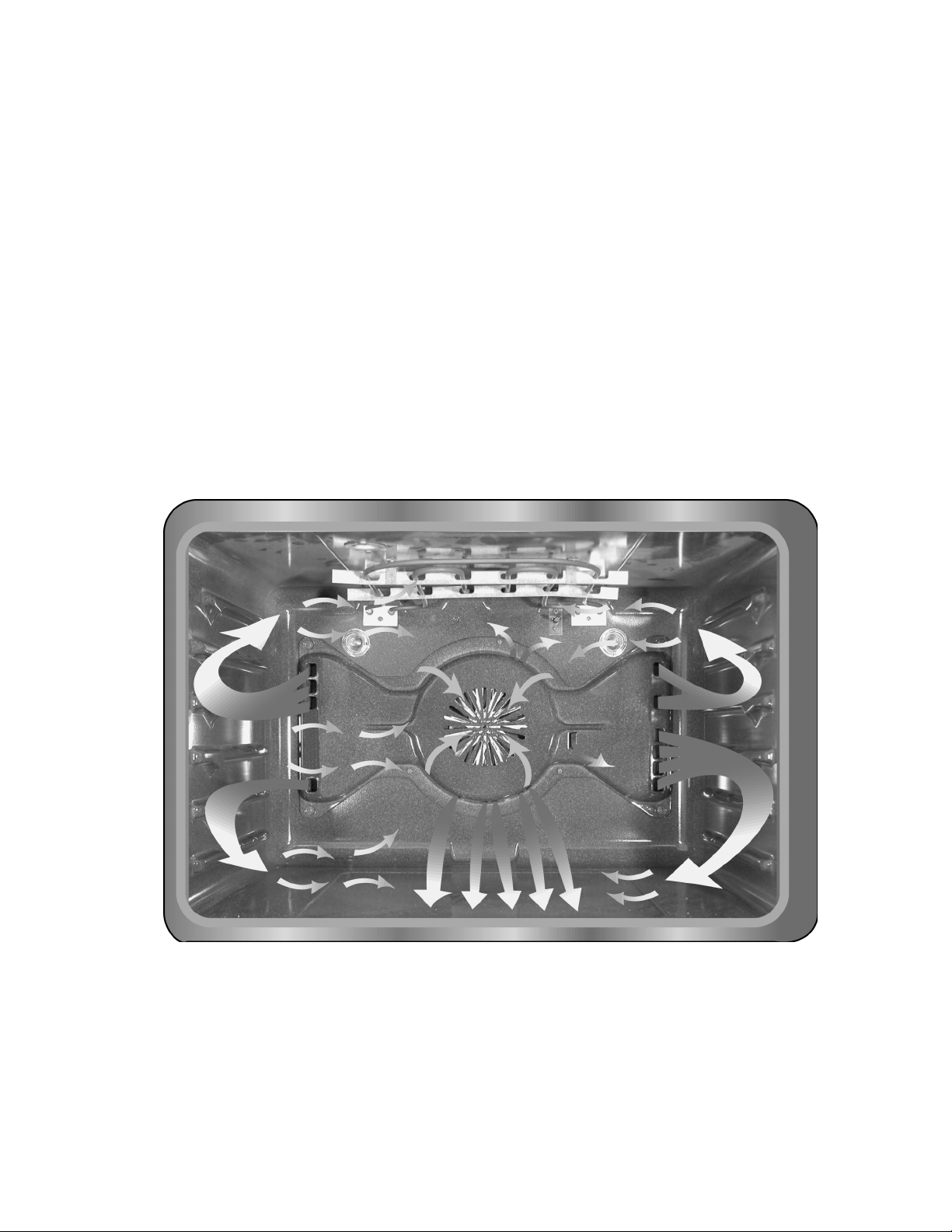
CONVECTION BOWTIE BAFFLE
AIRFLOW
The bowtie baffle provides a wider air flow
throughout the oven when using the convection cooking modes. The baffle, shown below,
is for an electric, Oxford-built oven. The gas
version of the Oxford oven has fewer air outlets, which eliminates too much air movement
during cooking (safety).
The correct baffle must always be used when
servicing a gas or electric oven. The oven cavity for Tulsa-built ranges is larger, (4.65 cu. ft.
as compared to 3.93 cu. ft.), and requires a
different baffle.
In a gas range, the convection fan will not turn
on for the first four minutes of operation. This
is to assure that a proper gas flame is present
before the convection fan starts to circulate air
in the oven cavity.
The fan blows hot air out the baffle along the
outer edges of the oven cavity, toward the front,
over the food, and back into the fan inlet. There
are air slots at the top and bottom of the center circle, which adds to the overall air flow
system.
Electric Oxford-Built Oven Convection Bowtie Baffle System
3-1
 Loading...