

Page 1

KSS
Speakers
KS COMPONENT SPEAKERS
KSS50 | KSS650 | KSS670
Owner’s Manual | English
Manual del Propietario | Español
Altavoz Componentes KS
Benutzerhandbuch | Deutsch
KS Komponenten-System
Manuel d’utilisation | Française
Haut-parleurs Composants KS
2017 KS Component Rev B.indd 12017 KS Component Rev B.indd 1 8/23/2016 12:22:38 PM8/23/2016 12:22:38 PM
Page 2

KS COMPONENT SYSTEM
Owner’s Manual
MODELS: KSS50 | KSS650 | KSS670
IMPORTANT SAFETY WARNING
Prolonged continuous operation of an amplifi er, speaker, or subwoofer in a distorted, clipped or overpowered manner can cause your audio system to overheat, possibly catching fi re and resulting in serious
damage to your components and/or vehicle. Amplifi ers require up to 4 inches (10cm) open ventilation.
Subwoofers should be mounted with at least 1 inch (2.5cm) clearance between the front of the speaker and
any surface.
KS COMPONENT SPEAKERS
The KICKER KS speakers offer an excellent upgrade to your vehicle’s factory sound system, delivering great
full-range sound at an amazing value! Whether dropping the KS speakers in a factory location or customizing
your install, their high-effi ciency design means less power is needed to play your music, while our use of
advanced materials and construction techniques ensures optimal performance for years to come.
PERFORMANCE
KS Component Speakers KSS50 KSS650 KSS670
Woofer [in, mm] 5-1/4, 130 6-1/2, 160 6-3/4, 165
Tweeter [in, mm] 1, 25 1, 25 1, 25
Dome Material Silk Silk Silk
Rated Impedance [Ω] 4 4 4
Peak Power Handling [ Watts] 200 250 250
Continuous Power Handling [Watts RMS] 100 125 125
Sensitivity [1W, 1m] 88 90 91
Frequency Response [Hz] 38-21k 35-21k 35-21k
Woofer Mounting Hole Diameter [in, mm] 4-1/2, 115 4-13/16, 123 5-9/16, 141
Woofer Top Mount Depth [in, mm] 1-3/4, 45 1-13/16, 46 1-13/16, 46
Flush Mount Tweeter Hole Diameter [in, mm] 1-3/4, 45 1-3/4, 45 1-3/4, 45
Flush Mount Tweeter Depth [in, mm] 11/16, 17 11/16, 17 11/16, 17
High Pass [dB], at Frequency [Hz] 12, 4,000 12, 4,000 12, 4,000
Low Pass [dB], at Frequency [Hz] 12, 4,000 12, 4,000 12, 4,000
High Frequency Output Attenuation [dB] 0, 4.5, 9 0, 4.5, 9 0, 4.5, 9
Note: All specifi cations and performance fi gures are subject to change. Please visit www.kicker.com for the
most current information. To get the best performance from your new KICKER speakers, we recommend using
genuine KICKER accessories and wiring. Please allow two weeks of break-in time for the speakers to reach optimum
performance.
Pro Tip: You’re a KICKER amplifi er and a few cables away from a full system upgrade that will dominate
any factory system! KICKER line of amplifi ers make it easy to upgrade to solid bass with your existing or
stock source unit. Also, ask your dealer about KICKER Subwoofer upgrades.
2
2017 KS Component Rev B.indd 22017 KS Component Rev B.indd 2 8/23/2016 12:22:40 PM8/23/2016 12:22:40 PM
Page 3
CONFIGURATION
Before mounting and wiring the KS component system, determine which confi guration you will use for the
speakers.
KS Speaker
Confi gurations
Coaxial great for space-limited applications
Separates optimal sound quality and improved
ADVANTAGES CONSIDERATIONS
or when separate tweeter mounting
is not possible
sonic imaging (with proper tweeter
mounting)
high frequencies may not be as
prominent | tweeter output may
need to be increased at crossover
trickier install | vehicle must have a
good tweeter mounting location
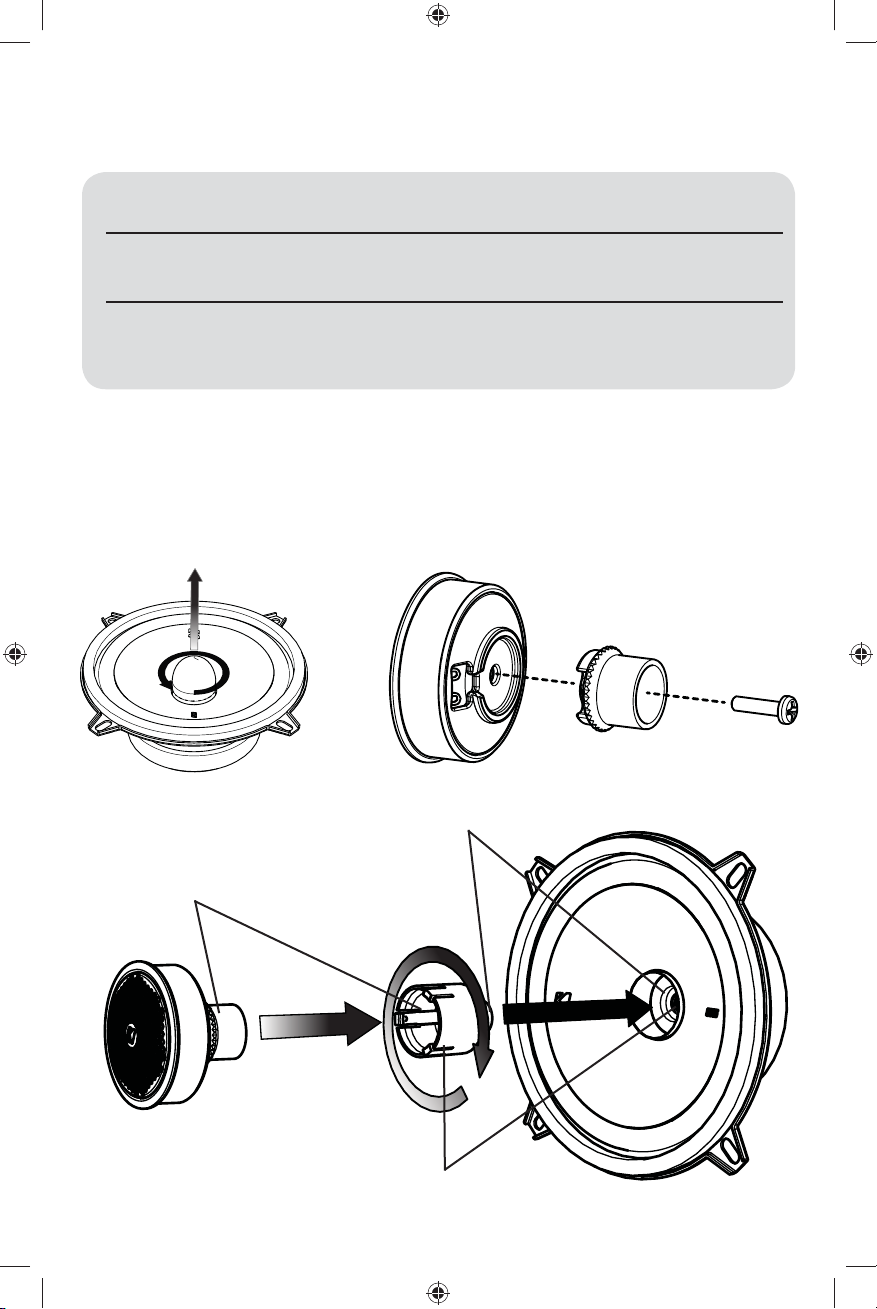
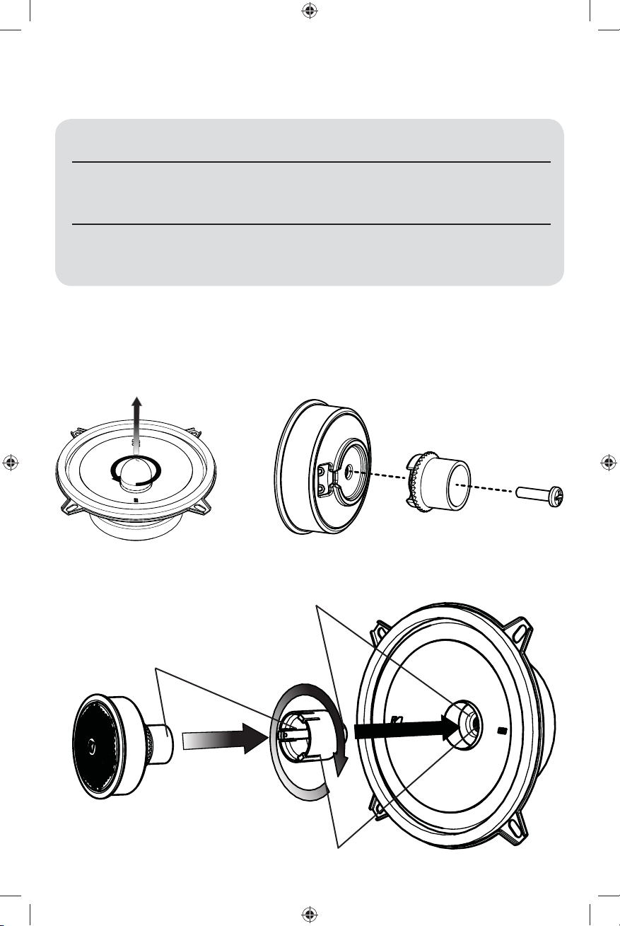
Coaxial Confi guration
The KS speakers come in a separates confi guration. For coaxial operation, use the following steps to
attach the tweeter.
remove phase plug
1.
Attach tweeter back to tweeter
2.
screw tweeter post to speaker
3.
snap tweeter to tweeter post
5.
thread tweeter wire through post and speaker
4.
3
2017 KS Component Rev B.indd 32017 KS Component Rev B.indd 3 8/23/2016 12:22:40 PM8/23/2016 12:22:40 PM
Page 4
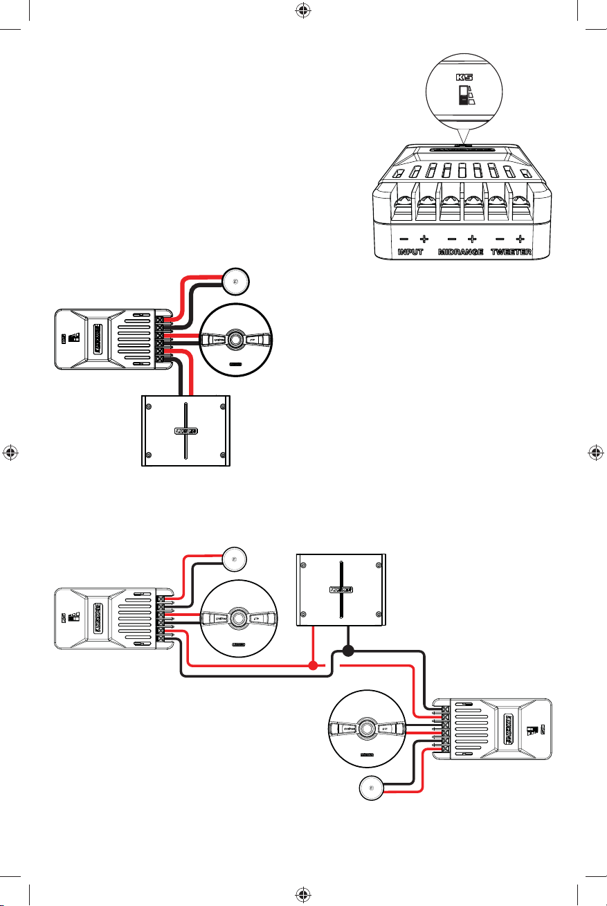
CROSSOVER & WIRING CONFIGURATION
We recommend using 16 gauge (or larger) wire. The KS Speakers
are rated at 4 ohms and work with any source unit or amplifi er
designed to operate at a 4 ohm load. Make sure your source
unit or amplifi er is rated for 4 ohm operation.
Use the tweeter attenuation switch to adjust the output level of
the tweeter to 0 dB, +4.5 dB, or +9 dB.
result in more volume from the tweeter.
Higher switch settings will
Crossover Wiring
One component set per channel
+
crossover
-
+
-
+-
source unit / amplifi er
Crossover Wiring
Two component sets per channel
+
-
+
-
-
+
Crossovers wired in parallel. Make sure your source
unit or amplifi er is rated for 2 ohm operation.
Requires two complete KS systems
(four woofers, four tweeters, four crossovers)
At least two amplifi er channels are needed for
stereo operation (only one channel is shown)
At least two amplifi er channels
are needed for stereo operation
(only one channel is shown)
-
+
-
+
-
+
-
+
4
2017 KS Component Rev B.indd 42017 KS Component Rev B.indd 4 8/23/2016 12:22:40 PM8/23/2016 12:22:40 PM
Page 5
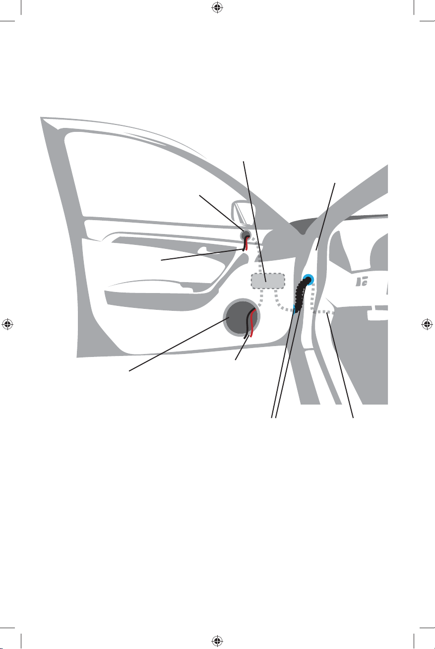
CROSSOVER MOUNTING
Mount the crossover in a location that is easy to access for wiring and tweeter output level adjustment.
Make sure that the crossover will not be exposed to water. The bottom of the car door is not a good
location. If you must mount the crossover in the car door, exercise caution as water can accumulate in the
bottom of the door. Keep the crossover high in the door and shielded from water.
KS crossover. (mounted
inside door panel)
door jamb
tweeter mounting hole
to tweeter lead wires
to woofer terminals
woofer mounting hole
rubber grommets from amplifi er or
If factory speaker wiring is not available in your desired location, it may be necessary to run speaker wire
through the door jamb. The speaker wire should be kept away from sharp edges and avoid the possibility of
getting pinched by the door. An existing grommet in the door jamb is the ideal place to run the speaker wire.
If the factory hole and grommet do not exist or are inaccessible, you must drill a hole to run the speaker wire
through the door jamb. Be careful not to drill into other wiring or existing door mechanisms. Any time a wire
is run through a hole, it is necessary to insert a rubber or plastic grommet to protect the wire from damage.
source unit
5
2017 KS Component Rev B.indd 52017 KS Component Rev B.indd 5 8/23/2016 12:22:40 PM8/23/2016 12:22:40 PM
Page 6

SPEAKER MOUNTING
The KICKER KS Speakers are designed for free-air applications and do not require a sealed enclosure for
optimum performance. It is important to isolate the sound coming from the front of the speaker from the
sound radiating from the back of the speaker. This is most easily accomplished by mounting the speakers
in a vehicle’s factory locations or in a location with a semi-isolated rear chamber (like the rear deck of a car
behind the rear seats).
If you are replacing factory speakers in their original locations, you may have to enlarge the speaker cutouts and pre-drill new screw holes using a 7/64” (2.5mm) bit. Custom mounting locations will require more
preparation and work. Make sure that the speaker will not interfere with trunk and door opening and closing
mechanisms and that the enclosed screws will not puncture the fuel tank, puncture wiring, or interfere with
any other mechanical parts on the underside of the mounting surface. Cycle the windows all the way down
and up.
If the speaker cut-out locations require you to cut metal, avoid structural metal and braces. If the door body
and panel cannot support the weight of the speaker, an optional reinforcing ring (thin piece of wood or
Medium Density Fiberboard) may be fastened or adhered to the door body.
door
door panel
speaker cut-out
KS speaker
6
2017 KS Component Rev B.indd 62017 KS Component Rev B.indd 6 8/23/2016 12:22:40 PM8/23/2016 12:22:40 PM
Page 7
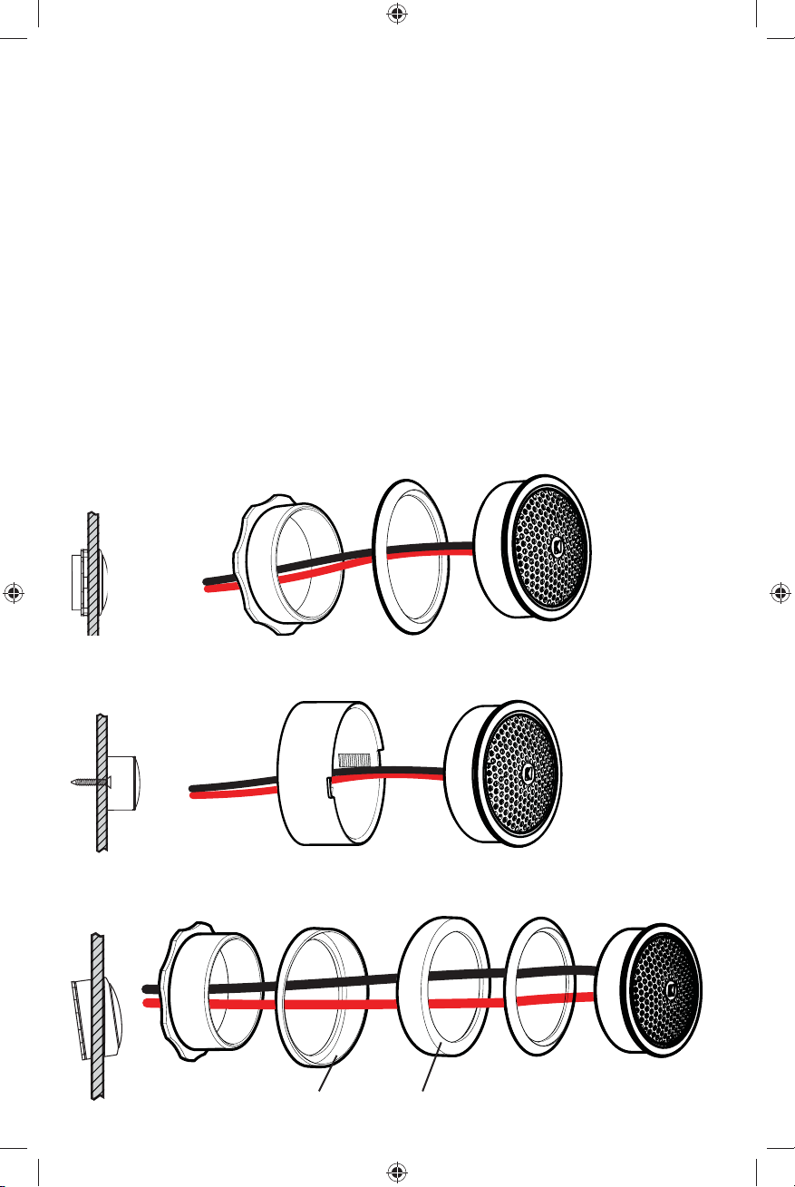
TWEETER MOUNTING
The tweeter can be separately mounted one of three ways: fl ush, angled and surface. For fl ush mounting
applications, choose a fl at location on the panel with space behind the panel to allow room for the short
mounting nut, motor structure, and tweeter. After checking the clearances, cut a 1-3/4” (44mm) diameter
mounting hole in the panel. Position the short mounting nut behind the panel. Feed the wire through the
optional fl ush ring, the hole in the panel, and the mounting nut. Mount the tweeter by screwing the mounting
nut onto the tweeter.
For surface mounting applications use the surface mount cup as a template and pre-drill one 7/64” (2.5mm)
screw hole (using two holes is optional) for attaching the surface mount cup to the panel and a 5/16” (8mm)
hole for the wires. An M3 pan-cross head wood screw is supplied to attach the surface mount cup to the
panel. Position the tweeter over the surface mount cup and screw it into position.
For angled mounting applications choose a fl at location on the panel with space behind the panel to allow
room for the long mounting nut, motor structure, tweeter post, and back angle ring. After checking the
clearances, cut a 1-3/4” (44mm) diameter mounting hole in the panel. Place the front angle ring in front of
the panel. Then place the wire and tweeter through the front angle ring and into the panel. Next, place the
wire through the back angle ring, place the back angle ring over the rear of the tweeter, and line-up the
narrow part of the front angle ring for the preferred angle of operation. Place the wire through the mounting
nut and loosely tighten the mounting nut around the tweeter. Rotate all the parts in unison until the tweeter is
angled in the desired direction. Secure the assembly by tightening the mounting nut.
Flush Mounting
panel
short mounting nut
fl ush ring
tweeter
Surface Mounting
panel
surface mount cup
tweeter
Angle Mounting
panel
2017 KS Component Rev B.indd 72017 KS Component Rev B.indd 7 8/23/2016 12:22:44 PM8/23/2016 12:22:44 PM
long mounting nut
back angle ring
inset surface
front angle ring
rounded surface
fl ush ring
decrease mounting depth by
removing tweeter back cover
tweeter
7
Page 8

Manual del propietario del
SISTEMA DE COMPONENTES KS
MODELO: KSS50 | KSS650 | KSS670
IMPORTANTE ADVERTENCIA DE SEGURIDAD
Funcionamiento continuo prolongado de un amplifi cador, altavoz o subwoofer de una manera distorsionada,
recortado o el exceso de potencia puede hacer que el sistema de audio se sobrecaliente, posiblemente
la captura de fuego y que resulta en graves daños a sus componentes y / o vehículo. Amplifi cadores
requieren hasta 4 pulgadas (10 cm) de ventilación abierta. Subwoofers deben montarse con el aclaramiento
(2,5 cm) por lo menos 1 pulgada entre la parte frontal del altavoz y cualquier superfi cie.
COMPONENTES KS
Los sistemas de Component de la serie KS de KICKER ofrecen una fi delidad de audio inigualable para
aplicaciones para vehículos. Ya sea para confi gurar el último sistema de sonido envolvente con altavoces
múltiples y subwoofer o simplemente para mejorar la versión de parlantes aburridos y sin vida de fábrica,
los sistemas de Componentes KS brindan el sonido de gama completa más placentero del mercado en la
actualidad!
RENDIMIENTO
Altavoz Componentes KS KSS5 KSS65 KSS67
Parlante Baja Frecuencia (Woofer) [pulgada, mm] 5-1/4, 130 6-1/2, 160 6-3/4, 165
Parlante Alta Frecuencia (Tweeter) [pulgada, mm] 1, 25 1, 25 1, 25
Material para la cúpula Seda Seda Seda
Impedancia nominal [Ω] 4 4 4
Manejo de la potencia máxima [Watts] 200 250 250
Manejo de la corriente continua [Watts RMS] 100 125 125
Sensibilidad [1W, 1m]
Respuesta en frecuencia [Hz] 38-21k 35-21k 35-21k
Diámetro del orifi cio de montaje woofer [pulgadas, mm] 4-1/2, 115 4-13/16, 123 5-9/16, 141
Profundidad del montaje del woofer [pulgadas, mm] 1-3/4, 45 1-13/16, 46 1-13/16, 46
Diámetro del orifi cio del montaje empotrado del tweeter [pulgadas, mm] 1-3/4, 45 1-3/4, 45 1-3/4, 45
Profundidad del montaje empotrado del tweeter [pulgadas, mm] 11/16, 17 11/16, 17 11/16, 17
Paso alto [dB] frecuencia de [Hz] 12, 4,000 12, 4,000 12, 4,000
Paso bajo [dB] frecuencia de [Hz] 12, 4,000 12, 4,000 12, 4,000
Atenuación de la salida de alta frecuencia [dB] 0, 4.5, 9 0, 4.5, 9 0, 4.5, 9
88 90 91
Consejo profesional: ¡Usted es un KICKER Amplifi cador, y unos pocos cables lejos de un sistema
fuerte estéreo! KICKER amplifi cadores lo hace fácil de mejorar sólido como una roca bajo con su existir
estéreo. Pregunte por favor su comerciante acerca de los aumentos de Amplifi cador de Kicker.
8
2017 KS Component Rev B.indd 82017 KS Component Rev B.indd 8 8/23/2016 12:22:44 PM8/23/2016 12:22:44 PM
Page 9
CONFIGURACIÓN
Antes de montar y realizar el cableado del sistema de componentes KS , determine qué confi guración
utilizará para los altavoces.
Confi guraciones de
los altavoces KS
Coaxial
Por separado Óptima calidad de sonido y mejor
VENTAJAS CONSIDERACIONES
Excelente para aplicaciones con
espacio limitado o cuando no es posible
el montaje del tweeter por separado
imagen acústica (con el montaje
adecuado del tweeter)
Es posible que las frecuencias altas
no sean tan prominentes | Es posible
que se necesite aumentar la salida
del tweeter en el crossover
Instalación más difícil | El vehículo
debe tener una buena ubicación
de montaje del tweeter
Confi guración coaxial
El sistema de componentes KS viene empaquetado en una confi guración por separado.
Para utilizar una confi guración coaxial, siga los pasos a continuación:
retire la clavija de fase
1.
Adhiera el altavoz de alta frecuencia detrás del altavoz
2.
atornille el montante del altavoz de alta
3.
frecuencia al altavoz
conecte el altavoz de alta frecuencia
5.
a su montante
pase el cable del altavoz de alta frecuencia a través del montante y altavoz
4.
2017 KS Component Rev B.indd 92017 KS Component Rev B.indd 9 8/23/2016 12:22:45 PM8/23/2016 12:22:45 PM
9
Page 10

CONFIGURACIÓN DEL CROSSOVER
Y CABLEADO
Se recomienda utilizar un cable calibre 16 (o más). Los
componentes KS están clasifi cados para 4 ohms y funcionan con
cualquier unidad fuente o amplifi cador diseñado para operar a una
carga de 4 ohms.
Asegúrese de que la unidad fuente o el amplifi cador estén
clasifi cados para funcionar con 4 ohms.
Utilice el interruptor de atenuación de agudos para ajustar el nivel
de salida del altavoz de agudos a 0 dB, +4,5 dB, o +9 dB. Si e
selecciona un valor mayor, el tweeter producirá más volumen.
Crossover Cableado
Un conjunto de componentes por canal
+
crossover
-
+
-
+-
unidad fuente / amplifi cador
Crossover Cableado
Dos conjuntos de componentes por canal
+
-
+
-
-
+
Crossover conectados en paralelo.
la unidad fuente o el amplifi cador estén clasifi cados
para funcionar con 2 ohms.
Asegúrese de que
Requiere dos sistemas KS completos (cuatro
woofer, cuatro tweeter y cuatro crossover).
Se necesitan al menos dos canales para
amplifi cadores para el funcionamiento en
estéreo (se muestra un solo canal).
Se necesitan al menos dos
canales para amplifi cadores
para el funcionamiento en
estéreo (se muestra un solo
canal).
-
+
-
+
-
+
-
+
10
2017 KS Component Rev B.indd 102017 KS Component Rev B.indd 10 8/23/2016 12:22:45 PM8/23/2016 12:22:45 PM
Page 11

MONTAJE DEL CROSSOVER
Monte el crossover en una ubicación que sea de fácil acceso para realizar el cableado y ajustar el nivel
de salida del tweeter. Asegúrese de que el crossover no quede en un lugar que se pueda mojar. La
parte inferior de la puerta del automóvil no es una buena ubicación. Si tiene que montar el crossover en
la puerta del automóvil, tenga cuidado ya que se puede acumular agua en la parte inferior de la puerta.
Mantenga el crossover en un lugar alto de la puerta y protegido del agua.
crossover KS (montado dentro del panel de la puerta)
orifi cio de montaje del tweeter
hacia las terminales del tweeter
orifi cio de montaje del woofer
hacia las terminales del woofer
arandelas de goma
batiente de la puerta
desde el amplifi cador
o unidad fuente
Si no hay cableado de fábrica para altavoz en el lugar deseado, puede ser necesario encaminar el cable
que se incluye a través de la jamba de la puerta. Este cable debe mantenerse alejado de los bordes
afi lados para que la puerta no pueda aplastarlo por accidente. La arandela de goma que pueda haber
en la jamba de la puerta es el lugar ideal para hacer pasar los cables de altavoz. Si no hay agujero con
arandela de goma de fábrica, o el que hay es inaccesible, es necesario hacer un agujero para pasar los
cables de altavoz por la jamba de la puerta. Tenga cuidado de no dañar otros cables o mecanismos de la
puerta. Cada vez que se hace pasar un cable a través de un agujero, es necesario insertar una arandela
de plástico o de goma para proteger el cable.
11
2017 KS Component Rev B.indd 112017 KS Component Rev B.indd 11 8/23/2016 12:22:45 PM8/23/2016 12:22:45 PM
Page 12

MONTAJE DEL WOOFER
Los altavoces Componentes Kicker KS han sido diseñados específi camente para montarlos en
aplicaciones al aire libre. Estos altavoces no necesitan caja sellada para dar un rendimiento óptimo.
Es importante separar el sonido radiado por delante del sonido radiado por detrás del excitador. Esta
separación se logra normalmente instalando el excitador en una ubicación de altavoz preestablecida de
fábrica o provista de una cámara trasera semiaislada.
Si va a cambiar los altavoces de fábrica sin cambiar su ubicación original, puede ser necesario agrandar
los cortes para altavoz y hacer nuevos agujeros piloto con una broca de 7/64 de plg. (2.5 mm).
Las ubicaciones de montaje personalizado requieren más preparación y trabajo. En cualquier caso,
asegúrese de que el altavoz no interfi era con los mecanismos de apertura y cierre de la puerta y de
la cajuela, y de que los tornillos incluidos no perforen el tanque de gasolina ni rompan el cableado ni
interfi eran con ninguna otra pieza mecánica debajo o detrás de la superfi cie de montaje. Suba y baje
completamente los vidrios de las ventanas.
Si la ubicación de los cortes para altavoz exige cortar metal, evite cortar los refuerzos o el metal
estructural. Si el panel y la estructura de la puerta no soportan el peso del altavoz, se puede fi jar o adherir
un anillo de refuerzo opcional (pieza delgada de madera o de Plancha de Fibra de Densidad Media
{Medium Density Fiberboard, MDF}) a la estructura de la puerta.
structura de la puerta
panel de la puerta
orifi cio del altavoz
KS altavoz
12
2017 KS Component Rev B.indd 122017 KS Component Rev B.indd 12 8/23/2016 12:22:46 PM8/23/2016 12:22:46 PM
Page 13

MONTAJE DEL TWEETER
El tweeter se puede montar de cuatro maneras: montaje al ras, en ángulo, y en superfi cie. Para
aplicaciones de montaje al ras, elija una ubicación plana en el panel con espacio sufi ciente detrás para
la tuerca de montaje corta y el tweeter. Después de controlar los espacios libres, corte un orifi cio de
montaje de 1-3/4” (44 mm) de diámetro en el panel. Coloque la tuerca de montaje detrás del panel.
Introduzca el cable a través del anillo al ras opcional, el orifi cio del panel y la tuerca de montaje. Atornille
la tuerca de montaje en el tweeter para montarlo.
Para aplicaciones de montaje en superfi cie, use la copa de montaje en superfi cie como plantilla a fi n de
hacer en el panel un agujero piloto de 7/64 de plg. (2.5 mm) para el tornillo de la copa y un agujero de
5/16 de plg. (8 mm) para los cables. Se incluye un tornillo M3 para madera de cabeza troncocónica con
ranuras en cruz para fi jar la copa en el panel. Coloque el tweeter sobre la copa y presiónelo hasta que
encaje en posición.
Para aplicaciones de montaje en ángulo, elija una ubicación plana en el panel con espacio sufi ciente
detrás para la tuerca de montaje larga, el tweeter y el anillo angular trasero. Después de controlar los
espacios libres, corte un orifi cio de montaje de 1-3/4” (44 mm) de diámetro en el panel. Coloque el
anillo angular delantero frente al panel. Luego, coloque el cable y el tweeter a través del anillo angular
trasero y en el panel. A continuación, coloque el cable a través del anillo angular trasero, coloque el anillo
angular trasero sobre la parte trasera del tweeter y alinee la parte angosta del anillo angular delantero para
lograr el ángulo de funcionamiento deseado. Coloque el cable a través de la tuerca de montaje y apriete
suavemente la tuerca de montaje alrededor del tweeter. Gire todas las piezas juntas hasta que el ángulo
del tweeter quede en la dirección que desee. Para asegurar el conjunto, apriete la tuerca de montaje.
Montaje al ras
panel
tuerca de montaje corta
anillo al ras
Montaje superfi cial
panel
Montaje en ángulo
panel
tuerca de montaje
larga
superfi cie de inserción
asiento para montaje en superfi cie
anillo angular
trasero
superfi cie redondeada
anillo angular
delantero
tweeter
tweeter
anillo al ras
Retire la cubierta posterior tweeter para
reducir la profundidad de montaje
tweeter
13
2017 KS Component Rev B.indd 132017 KS Component Rev B.indd 13 8/23/2016 12:22:49 PM8/23/2016 12:22:49 PM
Page 14

Handbuch für das
KS-KOMPONENTEN SYSTEM
MODELL: KSS50 | KSS650 | KSS670
WICHTIGE SICHERHEITSHINWEIS
Längerer Dauerbetrieb eines Verstärkers, Lautsprecher oder Subwoofer in einer verzerrt, abgeschnitten oder
über betriebene Weise können Sie Ihre Audio-System überhitzen , möglicherweise Feuer fangen und was zu
schweren Schäden an der Komponenten und / oder Fahrzeug. Die Verstärker benötigen bis 4 Zoll (10 cm)
offen Belüftung auf. Subwoofers sollte mit mindestens 1 Zoll (2,5 cm) Abstand zwischen der Vorderseite der
Lautsprecher und jeder Oberfl äche angebracht werden.
KS KOMPONENTEN
Ihr KS Komponenten-System wurde besonders für “Livin’ Loud” in der harten Autoumwelt entworfen. Es
ist Materialien und Konstruktion fortgeschritten beizubehalten, dass ideale Leistung jahrelang kommt.
LEISTUNG
KS Komponenten-System KSS5 KSS65 KSS67
Tieftöner [in, mm] 5-1/4, 130 6-1/2, 160 6-3/4, 165
Hochtöner [in, mm] 1, 25 1, 25 1, 25
Kalottenmaterial Silk Silk Silk
Nennimpedanz [Ω] 4 4 4
Spitzenbelastbarkeit [Watt] 200 250 250
Dauerbelastbarkeit [Watt RMS] 100 125 125
Sensitivität [1 W, 1 m] 88 90 91
Frequenzgang [Hz] 38-21k 35-21k 35-21k
Durchmesser Tieftöner-Montageloch [in, mm] 4-1/2, 115 4-13/16, 123 5-9/16, 141
Tiefe Tieftöner-Oberseitenmontage [in, mm] 1-3/4, 45 1-13/16, 46 1-13/16, 46
Lochdurchmesser bündig montierter Hochtöner [in, mm] 1-3/4, 45 1-3/4, 45 1-3/4, 45
Tiefe bündig montierter Hochtöner [in, mm] 11/16, 17 11/16, 17 11/16, 17
Hochpass [dB], bei Frequenz [Hz] 12, 4,000 12, 4,000 12, 4,000
Tiefpass [dB], bei Frequenz [Hz] 12, 4,000 12, 4,000 12, 4,000
Hochfrequenzausgangsdämpfung [dB] 0, 4.5, 9 0, 4.5, 9 0, 4.5, 9
Tipp: Sie sind ein KICKER Verstärker, ein Comp Subwoofer Gehäuse und ein paar Kabel weg von einem
starken Hifi -System! Die Kicker Verstärker machen es leicht, zu hartem Bass mit Ihrem originalen Radio zu
verbessern. Bitte fragen Sie Ihren Kicker Händler nach die Verstärker Nachrüstung.
14
2017 KS Component Rev B.indd 142017 KS Component Rev B.indd 14 8/23/2016 12:22:49 PM8/23/2016 12:22:49 PM
Page 15

ANORDNUNG
Bevor Sie das KS-Komponentensystem einbauen und verkabeln, sollten Sie die Anordnung der
Lautsprecher und der Frequenzweiche festlegen.
KS-Lautsprecheranordnung
Koaxial Bestens geeignet für Einbauten mit
Getrennt
VORTEILE HINWEISE
beschränktem Platz oder wenn ein
getrennter Einbau der Hochtöner
nicht möglich ist
Optimale Tonqualität und verbesserte
Klangabbildung (bei entsprechendem
Hochtöner-Einbau)
Hochfrequenzen treten möglicherweise nicht ganz hervor |
Hochtönerausgabe kann eine Verstärkung an der Frequenzweiche
erfordern
Komplizierterer Einbau | Fahrzeug
muss über einen guten HochtönerEinbauplatz verfügen
Koaxiale Anordnung
Das KS-Komponentensystem wird in verschiedenen Anordnungen geliefert. Für die koaxiale Anordnung
beachten führen Sie nachfolgende Schritte aus
Phasenstecker entfernen
1.
Bringen Sie den Hochtöner wieder an.
2.
Hochtönerpfosten an Lautsprecher schrauben
3.
Hochtöner an Hochtönerpfosten einrasten
5.
Hochtönerkabel durch Pfosten und Lautsprecher führen
4.
15
2017 KS Component Rev B.indd 152017 KS Component Rev B.indd 15 8/23/2016 12:22:50 PM8/23/2016 12:22:50 PM
Page 16

FREQUENZWEICHEN UND
VERKABELUNG-ANORDNUNG
Wir empfehlen die Verwendung eines 16-GaugeLautsprecherkabels (oder mehr). Die KS-Komponenten haben
eine Impedanz von 4 Ohm und sind für alle 4-ohmigen Quellen
oder Verstärker geeignet. Vergewissern Sie sich, dass Ihre
Quelle oder Verstärker für 4-Ohm-Betrieb ausgelegt ist.
Verwenden Sie den Hochtöner Bedämpfungsschalter den
Ausgangspegel des Hochtöners auf 0 dB, +4,5 dB oder +9 dB
einzustellen. J
die Lautstärke der Hochtöner.
e höher die die Schaltereinstellung ist, desto höher ist
Frequenzweiche Verkabelung
Ein Komponentenset pro Kanal
+
crossover
-
+
-
Für den Stereobetrieb sind mindestens zwei
Verstärkerkanäle erforderlich (Es wird nur ein
Kanal dargestellt).
+-
Quelle / Verstärker
Frequenzweiche Verkabelung
Zwei Komponentensets pro Kanal
+
-
+
-
-
+
Die Frequenzweichen sind dabei in Paralleler zu schalten.
Vergewissern Sie sich, dass Ihre Quelle oder
Verstärker für 2-Ohm-Betrieb ausgelegt ist.
Diese Anordnung erfordert zwei vollständige
KS-Systeme (vier Tieftöner, vier Hochtöner, vier
Frequenzweichen).
+
Für den Stereobetrieb sind
mindestens zwei Verstärkerkanäle
erforderlich (Es wird nur ein Kanal
dargestellt).
-
-
+
-
+
-
16
+
2017 KS Component Rev B.indd 162017 KS Component Rev B.indd 16 8/23/2016 12:22:50 PM8/23/2016 12:22:50 PM
Page 17

CROSSOVER-EINBAU
Bauen Sie die Frequenzweiche an einem leicht zugänglichen Ort für Verkabelung und Einstellung des
Hochtönerausgangspegels ein. Stellen Sie dabei sicher, dass die Frequenzweiche vor Wasser geschützt
ist. Der untere Teil der Tür ist kein geeigneter Ort. Wenn die Frequenzweiche in die Fahrzeugtür eingebaut
werden muss, treffen Sie entsprechende Vorsichtsmaßnahmen, da sich im unteren Teil der Tür Wasser
ansammeln kann. Bauen Sie daher die Frequenzweiche im oberen Teil der Tür, vor Wasser geschützt, ein.
KS-Frequenzweiche.
(Einbau an der Innenseite
der Türverkleidung)
Hochtöner-Montageloch
zum Hochtöner
Klemmen
Tieftöner-Montageloch
Wenn an der gewünschten Stelle keine werksseitigen Lautsprecherkabel verfügbar sind, müssen Sie
eventuell das Kabel durch den Türpfosten verlegen. Dabei ist darauf zu achten, dass das Kabel von
scharfen Kanten ferngehalten und nicht von der Tür eingeklemmt wird. Eine existierende Schutztülle
im Türpfosten wäre für die Verlegung des Lautsprecherkabels ideal. Falls kein vorgebohrtes Loch bzw.
keine Schutztülle vorhanden ist oder diese nicht zugänglich sind, müssen Sie ein Loch bohren, um das
Lautsprecherkabel durch den Türpfosten zu verlegen. Passen Sie dabei auf, dass Sie nicht andere Kabel
oder den Türmechanismus anbohren. Wenn Sie ein Kabel durch ein blankes Loch verlegen, müssen Sie
zum Schutz des Kabels eine Schutztülle aus Gummi oder Plastik einführen,
zum Tieftöner
Klemmen
Gummi Schutztüllen
Türpfosten
von Verstärker
oder Quelle
17
2017 KS Component Rev B.indd 172017 KS Component Rev B.indd 17 8/23/2016 12:22:50 PM8/23/2016 12:22:50 PM
Page 18

WOOFER-EINBAU
Ihre Kicker KS-Komponenten sind speziell für den Einbau in nicht geschlossenen Gehäusen gedacht. Die
Lautsprecher benötigen kein geschlossenes Gehäuse, um optimale Leistung zu bieten. Es ist wichtig, den
vorne aus dem Treiber austretenden Schall vom Schall zu trennen, der von der Rückseite des Treibers
kommt. Diese Trennung wird meist durch den Einbau an einer werksseitig vorgewählten Stelle erreicht,
oder an einer Stelle mit semiisoliertem Rückraum.
Wenn Sie werksseitig eingebaute Lautsprecher an den Original-Einbauorten ersetzen, müssen Sie
eventuell die Lautsprecheröffnungen vergrößern und mit einem 2,5-mm-Bohrer neue Schraubenlöcher
bohren. Spezielle Montagestellen erfordern mehr Vorbereitung und Arbeit. Stellen Sie auf jeden Fall sicher,
dass der Lautsprecher nicht das Öffnen und Schließen der Kofferraumklappe bzw. Tür behindert und dass
die beiliegenden Schrauben nicht in den Treibstofftank oder Kabel eindringen bzw. andere mechanische
Elemente an der Unterseite der Montageoberfl äche beschädigen. Fahren Sie die Fenster ganz nach unten
und oben.
Wenn es die Platzierung der Lautsprecheröffnungen erforderlich macht, Metall zu schneiden, müssen
Sie tragende Teile und Stützen vermeiden. Falls der Türkörper und die Türverkleidung das Gewicht des
Lautsprechers nicht unterstützen können, kann ein optionaler Verstärkungsring (ein dünnes Stück Holz
oder Faserplatte) angebracht oder am Türkörper befestigt werden. Bauen Sie den Lautsprecher wie
gezeigt.
Türkörper
Türverkleidung
Lautsprecherausschnitt
KS-Tieftöner
18
2017 KS Component Rev B.indd 182017 KS Component Rev B.indd 18 8/23/2016 12:22:51 PM8/23/2016 12:22:51 PM
Page 19

EINBAU HOCHTÖNER
Der Hochtöner kann auf drei Weisen eingebaut werden: Bündig, mit Winkel und auf der Oberfl äche. Für
den bündigen Einbau, wählen Sie eine ebene Fläche auf der Verkleidung mit ausreichend Platz hinter der
Verkleidung für die kurze Befestigungsmutter und den Hochtöner. Nachdem Sie den Freiraum überprüft
haben, schneiden Sie ein Montageloch mit 1-3/4 Zoll (44 mm) Durchmesser in die Verkleidung. Halten
Sie die Befestigungsmutter hinter die Verkleidung. Verlegen Sie das Kabel durch den optionalen Ring für
bündigen Einbau, durch das Loch in der der Verkleidung und durch die Befestigungsmutter. Befestigen
Sie den Hochtöner durch Festziehen der Befestigungsmutter.
Verwenden Sie bei der Oberfl ächeninstallation den Oberfl ächeninstallationsbecher als Schablone
und bohren Sie ein 2,5-mm-Schraubloch für die Befestigung des Oberfl ächeninstallationsbechers
an der Verkleidung und ein 8-mm-Loch für die Drähte vor. Für die Befestigung des
Oberfl ächeninstallationsbechers an der Verkleidung liegt eine M3-Flachkopfschraube mit Kreuzschlitz bei.
Platzieren Sie den Hochtöner über dem Oberfl ächeninstallationsbecher und drücken Sie ihn ein.
Für den winkeligen Einbau, müssen Sie eine ebene Fläche in der Verkleidung mit ausreichend Platz hinter
der Verkleidung für die lange Befestigungsmutter, den Hochtöner und den hinteren Winkelring auswählen.
Nachdem Sie den Freiraum überprüft haben, schneiden Sie ein Montageloch mit 1-3/4 Zoll (44 mm)
Durchmesser in die Verkleidung. Halten Sie den vorderen Winkelring vor die Verkleidung. Verlegen Sie
danach das Kabel und den Hochtöner durch den vorderen Winkelring und die Verkleidung. Verlegen
Sie als nächstes das Kabel durch den hinteren Winkelring, ziehen Sie diesen hinten auf den Hochtöner
und richten Sie den schmalen Teil auf den bevorzugten Winkel aus. Verlegen Sie das Kabel durch die
Befestigungsmutter und ziehen Sie diese leicht am Hochtöner fest. Drehen Sie alle Teile gleichzeitig bis
sich der Hochtöner in der gewünschten Position befi ndet. Ziehen Sie jetzt die Befestigungsmutter fest an.
Bündiger Einbau
Verkleidung
Ring für bündigen
Einbau
Hochtöner
Kurze
Befestigungsmutter
Einbau auf der berfl äche
Verkleidung
Einbau mit Winkelringen
Verkleidung
2017 KS Component Rev B.indd 192017 KS Component Rev B.indd 19 8/23/2016 12:22:54 PM8/23/2016 12:22:54 PM
Lange
Befestigungsmutter
Oberfl ächenbefestigungsschale
Hinterer
Winkelring
Einsatz
Abgerundete Oberfl äche
Vorderer
Winkelring
Hochtöner
Ring für bündigen
Einbau
Zurück Abdeckung entfernen, um
Hochtöner Einbautiefe reduzieren
Hochtöner
19
Page 20

KS Composants System
Notice d’Utilisation
MODELS: KSS50 | KSS650 | KSS670
IMPORTANT AVERTISSEMENT DE SÉCURITÉ
Prolongée fonctionnement continu d’un amplifi cateur, haut-parleur ou subwoofer d’une manière déformée,
coupée ou sur-alimenté peut provoquer votre système audio de surchauffer, éventuellement prendre feu
et causer des dommages graves à vos composants et / ou véhicule. Amplifi cateurs nécessitent jusqu’à 4
pouces (10cm) de ventilation ouverte. Subwoofers doivent être montés avec au moins 1 pouce (2,5 cm)
entre l’avant de l’enceinte et toute surface.
COMPOSANTS KS
Vos haut-parleurs de KS composants ont été conçus pour l’environnement automoteur dur. L’haut-parleur
utilise des matériels avancés et les techniques de construction pour maintenir l’exécution optimale pendant
des années pour venir.
PERFORMANCES
Haut-Parleur Composants KS KSS5 KSS65 KSS67
Haut-parleur des graves [po ; mm] 5-1/4 ; 130 6-1/2 ; 160 6-3/4 ; 165
Haut-parleur des aigus [po ; mm] 1 ; 25 1 ; 25 1 ; 25
Matière du dôme Soie Soie Soie
Impédance nominale [Ω] 4 4 4
Puissance admissible maximale [W] 200 250 250
Puissance admissible continue [watts RMS] 100 125 125
Sensibilité [1 W, 1 m] 88 90 91
Réponse en fréquence [Hz] 38 à 21 k 35 à 21 k 35 à 21 k
Diam. du trou de montage supérieur du haut-parleur des graves [po ; mm] 4-1/2 ; 115 4-13/16 ; 123 5-9/16 ; 141
Profondeur de montage supérieur du haut-parleur des graves [po ; mm] 1-3/4 ; 45 1-13/16 ; 46 1-13/16 ; 46
Diam. du trou de montage encastré du haut-parleur des aigus [po ; mm] 1-3/4 ; 45 1-3/4 ; 45 1-3/4 ; 45
Profondeur de montage encastré du haut-parleur des aigus [po ; mm] 11/16 ; 17 11/16 ; 17 11/16 ; 17
Passe-haut [dB]; à la fréquence [Hz] 12 ; 4,000 12 ; 4,000 12 ; 4,000
Passe-bas [dB]; à la fréquence [Hz] 12 ; 4,000 12 ; 4,000 12 ; 4,000
Atténuation haute fréquence en sortie [dB] 0 ; 4,5 ; 9 0 ; 4,5 ; 9 0 ; 4,5 ; 9
Astuce de pro : Vous êtes un KICKER Amplifi cateur, un caisson d’extrêmes graves, et quelques câbles
loin d’un grand système de stéréo ! Les amplifi cateurs le font facile à améliorer le basse balancer-solide
avec votre radio existante.
20
2017 KS Component Rev B.indd 202017 KS Component Rev B.indd 20 8/23/2016 12:22:54 PM8/23/2016 12:22:54 PM
Page 21

CONFIGURATION
Avant de monter et de câbler le système composant KS, déterminer la confi guration à utiliser pour les
haut-parleurs et le fi ltre passif.
Confi gurations
Haut-parleur KS
Coaxiale Idéal pour des applications
Séparée Qualité sonore optimale et imagerie
AVANTAGES REMARQUES
confi nées ou si le montage d’un
tweeter séparé n’est pas possible
sonique améliorée (avec un
montage de tweeter correct)
Les hautes fréquences ne sont
pas toujours aussi puissantes |la
sortie tweeter peut avoir besoin
d’être augmentée augmentée au
niveau du fi ltre passif
Installation plus délicate | le véhicule
doit disposer d’un emplacement
adapté au montage du tweeter
Confi guration coaxiale
Le système composant KS est conditionné pour des confi guration distinctes. Pour utiliser une
confi guration coaxiale, suivre les étapes suivantes :
retirer la fi che de phase
1.
Remise en place du haut-parleur des aigus
2.
Visser le support de tweeter sur le haut-parleur
3.
Clipser le tweeter sur le support de tweeter
5.
Faire passer le câble du tweeter à travers le support et le haut-parleur
4.
21
2017 KS Component Rev B.indd 212017 KS Component Rev B.indd 21 8/23/2016 12:22:55 PM8/23/2016 12:22:55 PM
Page 22

CONFIGURATION FILTRE PASSIF
ET CÂBLAGE
Nous conseillons d’utiliser du fi l de calibre 16 (ou supérieur).
Les composantsiaux KS ont une valeur nominale de 4 ohms
et fonctionnent avec n’importe quelle source ou n’importe quel
amplifi cateur conçu pour une charge de 4 ohms. S’assurer
que la source ou l’amplifi cateur est prévu pour un
fonctionnement à 4 ohms.
Utilisez le commutateur tweeter d’atténuation pour régler le niveau
de sortie du tweeter à 0 dB, +4,5 dB ou +9 dB. Des réglages
d’interrupteur plus élevés se traduiront par plus de volume à la sortie
du haut-parleur d’aigus.
Filtre passif Câblage
Un composant défi ni par canal
+
crossover
-
+
-
+-
source unit / amplifi er
Filtre passif Câblage
Deux composants défi nis par canal
+
-
+
-
-
+
Filtres passifs câblés en parallèle. S’assurer que
la source ou l’amplifi cateur est prévu pour un
fonctionnement à 2 ohms.
Au moins deux canaux amplifi cateurs sont
requis pour pour une exploitation stéréo (un
seul canal est représenté)
Requiert deux systèmes KS complets (quatre
woofers, quatre tweeters, quatre fi ltres passifs)
Au moins deux canaux
amplifi cateurs sont requis pour une
exploitation stéréo (un seul canal
est représenté)
-
+
-
+
-
+
-
22
2017 KS Component Rev B.indd 222017 KS Component Rev B.indd 22 8/23/2016 12:22:55 PM8/23/2016 12:22:55 PM
+
Page 23

MONTAGE DU FILTRE PASSIF
Monter le fi ltre passif dans un emplacement facile d’accès pour le câblage et le réglage de niveau de sortie
du tweeter. S’assurer que le fi ltre passif n’est pas exposé à l’eau. Le bas de la porte du véhicule n’est pas
un bon endroit. Si le fi ltre passif doit être monté dans la portière, faire attention dans la mesure où l’eau
risque de s’accumuler au bas de la portière. Lefi ltre passif doit rester en haut de la portière et être protégé
de l’eau.
fi ltre passif KS. (montage à
l’intérieur du panneau de porte)
jambage de porte
trou de montage du tweeter
vers les bornes du
tweeter
vers les bornes du woofer
trou de montage du woofer
passe-fi ls en caoutchouc de l’amplifi cateur
S’il n’y a pas de précâblage d’installation audio à l’emplacement voulu, il peut être nécessaire de faire passer
les fi ls de haut-parleur par le montant de la portière. Éloignez ces fi ls des arêtes vives et évitez qu’ils ne
risquent d’être pincés par la portière. L’idéal est de faire passer les fi ls de haut-parleur par un passe-fi ls de
montant de portière existant. S’il n’y a pas de trou ni passe-fi ls accessibles, percez un trou de passage des
fi ls de haut-parleur dans le montant de portière. Veillez à ne pas percer d’autres fi ls ou les mécanismes de
portes. Pour faire passer un fi l électrique dans un trou, insérez un passe-fi ls en caoutchouc ou en plastique
afi n de protéger le fi l.
ou de la source
23
2017 KS Component Rev B.indd 232017 KS Component Rev B.indd 23 8/23/2016 12:22:55 PM8/23/2016 12:22:55 PM
Page 24

MONTAGE DU WOOFER
Les composantsiaux Kicker KS ont été spécialement conçus pour un montage sans enceinte. Leur
fonctionnement optimal ne nécessite pas d’enceinte close. Il est important d’isoler le son sortant par
l’avant du haut-parleur et le son diffusé à l’arrière du haut-parleur. En général, cette isolation est obtenue en
installant le haut-parleur dans un emplacement standard ou dans un emplacement pourvu d’une chambre
arrière semi-isolée.
Dans le cas du remplacement de haut-parleurs d’origine en utilisant les mêmes emplacements, il peut être
nécessaire d’agrandir les découpes de haut-parleurs et de percer de nouveaux trous pour les vis, à l’aide
d’un foret de 2,5 mm. Les emplacements de montage sur mesure demandent davantage de préparation
et de travail. Dans tous les cas, veillez à ce que le haut-parleur ne gêne pas les mécanismes d’ouverture
et de fermeture du coffre et des portières, et que les vis fournies ne percent pas le réservoir de carburant
ni les câbles, et ne gênent aucune autre pièce mécanique à l’envers de la surface de montage. Ouvrez
complètement les vitres, puis refermez-les.
Si les emplacements des découpes de haut-parleurs obligent à couper des parties métalliques, évitez la
structure et les renforts métalliques. Si le poi KS du haut-parleur est excessif pour la portière et sa garniture,
un anneau de renforcement facultatif (morceau de bois mince ou panneau de fi bres de bois de densité
moyenne) peut être fi xé ou collé à la portière.
corps de
porte
panneau de porte
découpe de haut-parleur
KS speaker
24
2017 KS Component Rev B.indd 242017 KS Component Rev B.indd 24 8/23/2016 12:22:56 PM8/23/2016 12:22:56 PM
Page 25

MONTAGE DU TWEETER
Le haut-parleur d’aigus peut être monté de tres différentes façons : montage affl eurant, angulaire et en
surface. Pour des applications de montage encastré, choisir un emplacement plat sur le panneau en
laissant un espace derrière le panneau pour l’écrou de montage court et le hautparleur d’aigus. Après avoir
vérifi é les dégagements, découper un trou de montage de 1-3/4” (44 mm) de diamètre dans le panneau.
Positionner l’écrou de montage derrière le panneau. Faire passer le fi l à travers la bague affl eurante en
option, le trou pratiqué dans le panneau et l’écrou de montage. Monter le tweeter en vissant l’écrou de
montage sur le tweeter.
Pour un montage en surface, utilisez la coupelle de montage en surface comme gabarit et percez un trou
de 2,5 mm pour la fi xation de la coupelle au panneau, et un trou de 8 mm pour les fi ls. Une vis à bois M3 à
tête cruciforme est fournie pour la fi xation de la coupelle de montage en surface au panneau. Mettez le hautparleur d’aigus sur la coupelle de montage en surface et appuyez pour le mettre en place.
Pour des applications de montage angulaire, choisir un emplacement plat sur le panneau en laissant un
espace derrière le panneau pour l’écrou de montage long, le haut-parleur d’aigus et la bague de montage
en angle. Après avoir vérifi é les dégagements, découper un trou de montage de 1-3/4” (44 mm) de
diamètre dans le panneau. Placer la bague angulaire avant devant le panneau. Puis insérer le fi l et le tweeter
à travers la bague angulaire avant et le panneau. Ensuite, faire passer le fi l à travers la bague angulaire
arrière, faire passer la bague angulaire arrière au-dessus de la partie arrière du tweeter et aligner la partie
étroite de la bague angulaire avant pour trouver l’angle d’exploitation préféré. Faire passer le fi l à travers
l’écrou de montage et serrer légèrement l’écrou de montage autour du tweeter. Faire tourner toutes les
pièces en même temps jusqu’à ce que le tweeter adopte la bonne direction angulaire. Fixer l’ensemble en
serrant l’écrou de montage.
Montage encastré
panneau
écrou de
montage
court
bague affl
eurante
tweeter
Montage en surface
panneau
coupelle de bâti
de surface
Montage angulaire
panneau
2017 KS Component Rev B.indd 252017 KS Component Rev B.indd 25 8/23/2016 12:22:59 PM8/23/2016 12:22:59 PM
écrou de montage
long
surface encastrée
bague angulaire
arrière
surface arrondie
bague angulaire
avant
bague affl
eurante
Retirez la couverture arrière pour
réduire la profondeur de montage
tweeter
tweeter
25
Page 26

ACOUSTICS LIMITED WARRANTY
When purchased from an Authorized KICKER Dealer, KICKER warrants this product to be free from defects
in material and workmanship under normal use for a period of ONE (1) YEAR from date of original purchase.
If this product is identifi ed as “Refurbished” or “B Goods”, the warranty is limited to a period of THREE (3)
MONTHS from date of original purchase. In all cases you must have the original receipt. Should service
be necessary under this warranty for any reason due to manufacturing defect or malfunction during the
warranty period, KICKER will repair or replace (at its discretion) the defective merchandise with equivalent
merchandise. Warranty replacements may have cosmetic scratches and blemishes. Discontinued products
may be replaced with more current equivalent products. This warranty is valid only for the original purchaser
and is not extended to owners of the product subsequent to the original purchaser. Any applicable implied
warranties are limited in duration to a period of the express warranty as provided herein beginning with the
date of the original purchase at retail, and no warranties, whether express or implied, shall apply to this
product thereafter. Some states do not allow limitations on implied warranties; therefore, these exclusions
may not apply to you. This warranty gives you specifi c legal rights; however you may have other rights that
vary from state to state.
WHAT TO DO IF YOU NEED WARRANTY OR SERVICE:
Defective merchandise should be returned to your local Authorized Stillwater Designs (KICKER) Dealer
for warranty service. Assistance in locating an Authorized Dealer can be found at www.kicker.com or by
contacting Stillwater Designs directly. You can confi rm that a dealer is authorized by asking to see a current
authorized dealer window decal.
If it becomes necessary for you to return defective merchandise directly to Stillwater Designs (KICKER), call
the KICKER Customer Service Department at (405) 624-8510 for a Return Merchandise Authorization (RMA)
number. Package only the defective items in a package that will prevent shipping damage, and return to:
Stillwater Designs, 3100 North Husband St, Stillwater, OK 74075
The RMA number must be clearly marked on the outside of the package. Please return only defective
component systems. The return of functioning items increases your return freight charges. Non-defective
items will be returned freightcollect to you. For example, if a subwoofer is defective, only return the defective
subwoofer, not the entire enclosure. Include a copy of the original receipt with the purchase date clearly
visible, and a “proof-of-purchase” statement listing the Customer’s name, Dealer’s name and invoice
number, and product purchased. Warranty expiration on items without proof-of-purchase will be determined
from the type of sale and manufacturing date code. Freight must be prepaid; items sent freight-collect, or
COD, will be refused.
WHAT IS NOT COVERED?
This warranty is valid only if the product is used for the purpose for which it was designed. It does not cover:
o Damage due to improper installation
o Subsequent damage to other components
o Damage caused by exposure to moisture, excessive heat, chemical cleaners, and/or UV radiation
o Damage through negligence, misuse, accident or abuse.
Repeated returns for the same damage may be considered abuse
o Any cost or expense related to the removal or reinstallation of product
o Speakers damaged due to amplifi er clipping or distortion
o Items previously repaired or modifi ed by any unauthorized repair facility
o Return shipping on non-defective items
o Products with tampered or missing barcode labels
o Products with tampered or missing serial numbers
o Products returned without a Return Merchandise Authorization (RMA) number
o Products purchased from an UNAUTHORIZED dealer
o Freight Damage
o The cost of shipping product to KICKER
o Service performed by anyone other than KICKER
NOTE: All specifi cations and performance fi gures are subject to change. Please visit the www.kicker.com for the most current information.
26
2017 KS Component Rev B.indd 262017 KS Component Rev B.indd 26 8/23/2016 12:23:00 PM8/23/2016 12:23:00 PM
stillwaterdesigns
44KSS-B-201608023
Page 27

HOW LONG WILL IT TAKE?
KICKER strives to maintain a goal of one-week service for all acoustics (subwoofers, midrange drivers,
tweeters, crossovers, etc) returns. Delays may be incurred if lack of replacement inventory or parts is
encountered. Failure to follow these steps may void your warranty. Any questions can be directed to the
KICKER Customer Service Department at (405) 624-8510. Contact your International KICKER dealer or
distributor concerning specifi c procedures for your country’s warranty policies.
INTERNATIONAL WARRANTY
Contact your International KICKER dealer or distributor concerning specifi c procedures for your country’s
warranty policies.
Our goods come with guarantees that cannot be excluded under the Australian Consumer Law. You
are entitled to a replacement or refund for a major failure and for compensation for any other reasonably
foreseeable loss or damage. You are also entitled to have the goods repaired or replaced if the goods fail to
be of acceptable quality and the failure does not amount to a major failure.
GARANTÍA INTERNACIONAL Versión Español
Comuníquese con su concesionario o distribuidor KICKER internacional para obtener infor ación sobre
procedimientos específi cos relacionados con las normas de garantía de su país.
La frase “combustible para vivir la vida Livin’ Loud™ a todo volumen” se refi ere al entusiasmo por la vida que
la marca KICKER de estéreos de automóvil representa y a la recomendación a nuestros clientes de que
vivan lo mejor posible (“a todo volumen”) en todo sentido. La línea de altavoces y amplifi cadores KICKER es
la mejor del mercado de audio de automóviles y por lo tanto representa el “combustible” para vivir a todo
volumen en el área de “estéreos de automóvil” de la vida de nuestros clientes. Recomendamos a todos
nuestros clientes que obedezcan todas las reglas y reglamentos locales sobre ruido en cuanto a los niveles
legales y apropiados de audición fuera del vehículo.
INTERNATIONALE GARANTIE Deutsche Version
Nehmen Sie mit Ihren internationalen KICKER-Fachhändler oder Vertrieb Kontakt auf, um Details über die
Garantieleistungen in Ihrem Land zu erfahren.
Der Slogan “Treibstoff für Livin’ Loud” bezieht sich auf die mit den KICKER-Autostereosystemen assoziierte
Lebensfreude und die Tatsache, dass wir unsere Kunden ermutigen, in allen Aspekten ihres Lebens nach
dem Besten (“Livin’ Loud”) zu streben. Die Lautsprecher und Verstärker von KICKER sind auf dem Markt
für Auto-Soundsysteme führend und stellen somit den “Treibstoff” für das Autostereoerlebnis unserer
Kunden dar. Wir empfehlen allen unseren Kunden, sich bezüglich der zugelassenen und passenden
Lautstärkepegel außerhalb des Autos an die örtlichen Lärmvorschriften zu halten.
GARANTIE INTERNATIONALE Version Française
Pour connaître les procédures propres à la politique de garantie de votre pays, contactez votre revendeur ou
distributeur International KICKER.
AVERTISSEMENT: Les haut-parleurs KICKER ont la capacité de produire des niveaux sonores pouvant
endommager l’ouïe de façon irréversible ! L’augmentation du volume d’un système jusqu’à un niveau
présentant une distorsion audible endommage davantage l’ouïe que l’écoute d’un système sans distorsion
au même volume. Le seuil de la douleur est toujours le signe que le niveau sonore est trop élevé et risque
d’endommager l’ouïe de façon irréversible. Réglez le volume en faisant prevue de bon sens!
L’expression “ carburant pour vivre plein pot “ fait référence au dynamisme de la marque KICKER
d’équipements audio pour véhicules et a pour but d’encourager nos clients à faire le maximum (“ vivre plein
pot “) dans tous les aspects de leur vie. Les haut-parleurs et amplifi cateurs KICKER sont les meilleurs dans
le domaine des équipements audio et représentent donc pour nos client le “ carburant pour vivre plein pot “
dans l’aspect “ installation audio de véhicule “ de leur vie. Nous encourageons tous nos clients à respecter
toutes les lois et réglementations locales relatives aux niveaux sonores acceptables à l’extérieur des
véhicules.
P.O. Box 459 • Stillwater, Oklahoma 74076 • USA • (405) 624–8510
27
2017 KS Component Rev B.indd 272017 KS Component Rev B.indd 27 8/23/2016 12:23:00 PM8/23/2016 12:23:00 PM
Page 28

©2016 Stillwater Designs
2017 KS Component Rev B.indd 282017 KS Component Rev B.indd 28 8/23/2016 12:23:00 PM8/23/2016 12:23:00 PM
 Loading...