

Page 1
96M11226
Digital Calibration Fiberoptic Sensors
Warning
• This product is just intended to detect the object(s). Do
not use this product for the purpose to protect a human
body or a part of human body.
• This product is not intended for use as explosion-proof
product. Do not use this product in a hazardous
location and/or potentially explosive atmosphere.
FS-V1(P)
Instruction Manual
Read this manual before using the product in order to achieve maximum performance.
Keep this manual in a safe place after reading it so that it can be used at any time.
Warning
NOTICE
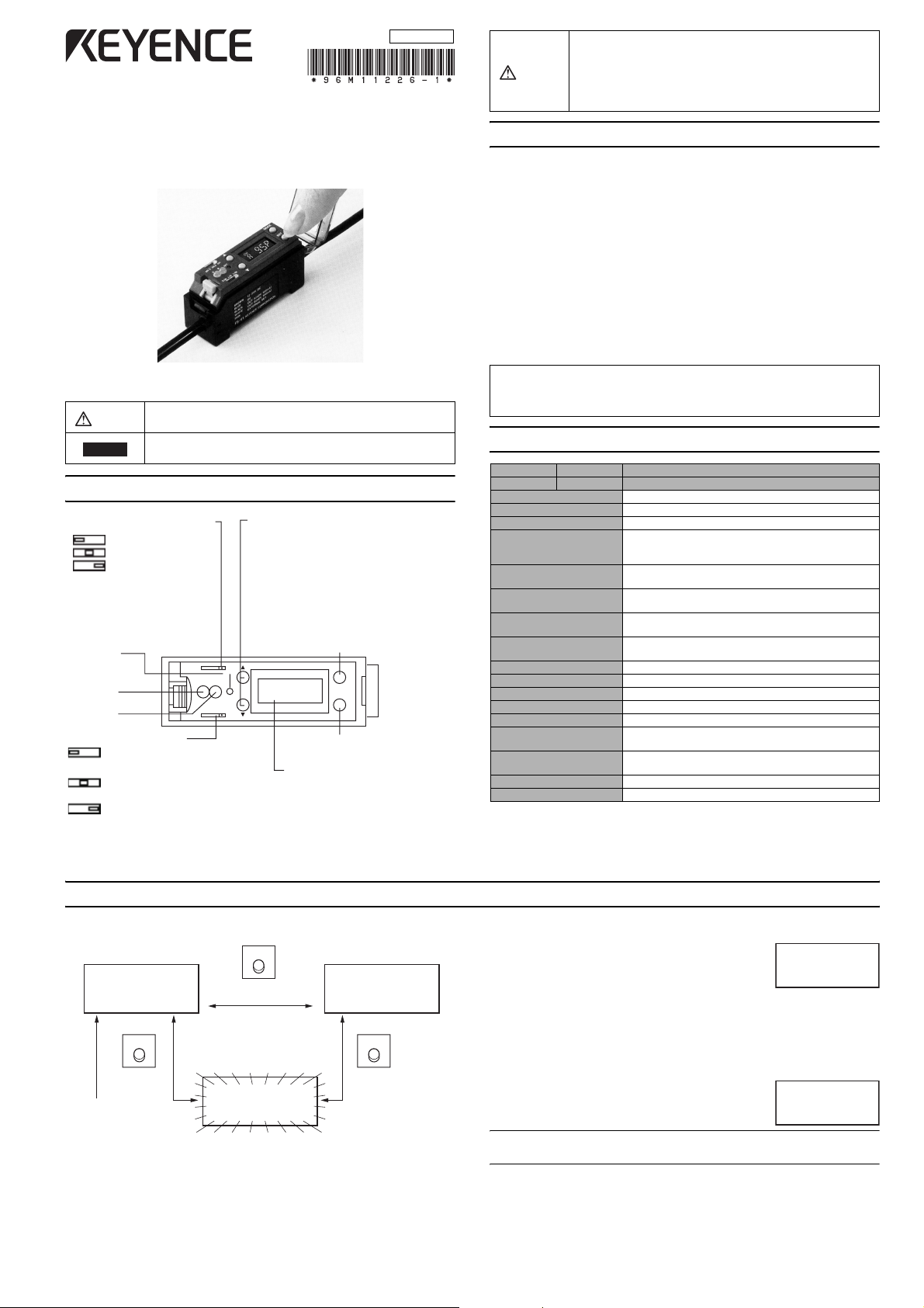
PART NAMES AND FUNCTIONS
Output timer selector switch UP/DOWN key
Note: Outputs of both A and B
are set to the same mode.
Calibration
indicator
Output A
indicator
Output B
indicator
Output selector switch
*Use the UP/DOWN key together with the MODE selector button.
It indicates a hazardous situation which, if not avoided,
could result in death or serious injury.
It indicates a situation which, if not avoided, could result in
product damage as well as property damage.
OFF-delay 40 ms
ON-delay 40 ms
Timer OFF
AB
DARK-ON for both outputs
A and B
LIGHT-ON for output A and
DARK-ON for output B
LIGHT-ON for both outputs
A and B
• Changes sensitivity setting value.
• Selects channel (expansion unit).
MODE selector button
• Selects displayed data.
• Excess gain
• Light intensity
• Setting value
• Selects channel (expansion unit). *
• Enables/disables key protect. *
MODE
CH
2
#
SET
SET button
Sets sensitivity.
LCD display monitor
Turns display red when the
selected channel is ON.
Turns display green when the
selected channel is OFF.
PRECAUTIONS ON REGULATIONS AND STANDARDS
UL Certificate
This product is an UL/C-UL Listed product.
• UL File No. E301717
• Category NRKH,NRKH7
• Enclosure Type 1 (Based on UL50)
Be sure to consider the following specifications when using this product
as an UL/C-UL Listed Product.
• Use the power supply with Class 2 output defined in NFPA70 (NEC:
National Electrical Code).
• Power supply/ Control input/ Control output circuits shall be connected to a single Class 2 source only.
• Use with the over current protection device which is rated 24 V or
more and not more than 2 A.
Accessories
• Instruction manual (x 1)
• Mounting bracket (x 1)
SPECIFICATIONS
Model NPN output
Light source Red LED
Response time 250 μs
Operation mode LIGHT-ON/DARK-ON (switch-selectable)
Indicators
Timer function ON-delay: 40 ms, OFF-delay: 40 ms,
External calibration
input signal
Control output
(2 outputs)
Protection circuit Reverse polarity protection, Over-current protection,
Power supply voltage 12 to 24 VDC ±10%, Ripple (P-P) 10% max., Class 2
Current consumption 50 mA max.
Ambient illumination Candescent lamp: 10,000 lx max., Sunlight: 20,000 lx max.
Ambient temperature -10 to +55°C (14 to 131°F), No freezing
Relative humidity 35 to 85%, No condensation
Vibration 10 to 55 Hz, 1.5 mm double amplitude in X, Y and
Shock immunity 500 m/s2 in X, Y and Z directions,
Housing material Body/Cover: Polycarbonate
Weight Approx. 80 g (including 2 m cable)
1 A "P" following the model number indicates PNP-output type.
2 When several units are connected, the allowable ambient temperature changes depending
on the following conditions. To connect several units, be sure to mount them to a DIN rail
(metal DIN rail). Make sure that the output current is 20 mA. max.
• When 3 to 10 units are connected: -10 to +50 °C
• When 11 to 16 units are connected: -10 to +45 °C
PNP output
Output indicators: 2 Red LED’s,
Received light intensity display: LCD (Red/Green LED back-lit)
Calibration indicator: Yellow LED,
Timer OFF (switch selectable)
NPN or PNP open-collector 24 V 100 mA max.,
Residual voltage : 1 V max.
FS-V1
FS-V1P
contact, solid state
Surge protection
Z directions for two hours
three times each
SELECTING DISPLAYED DATA
Excess gain (%)
CH
#
2
MODE
Press this
button once.
Channel display:
Indicates the
channel of the
expansion unit
currently being
monitored.
* The setting value flashes on and off.
(Factory-setting is Excess gain.)
MODE
Hold down this button
for longer than 3 seconds.
Setting value (4 digits)
CH
#
Received light intensity
(4 digits)
CH
#
MODE
Press this
button once.
Displaying excess gain
Received light intensity is converted by defining
the setting value as 100 P (%).
• Stable LIGHT status is obtained with 110 P (%) or more.
• Stable DARK status is obtained with 90 P (%) or less.
You can adjust the sensitivity in increments of 1%.
CH
# 2
¨ Refer to P.2.
Displaying received light intensity
Received light intensity is displayed approximately 4000 is the maximum setting.
Note: The MAX and MIN values vary depending on the fiber unit connected.
CH
#
Displaying a setting value
The current setting value is displayed. You can adjust the setting value
in increments of 1 .
¨ Refer to P.2.
1
Page 2
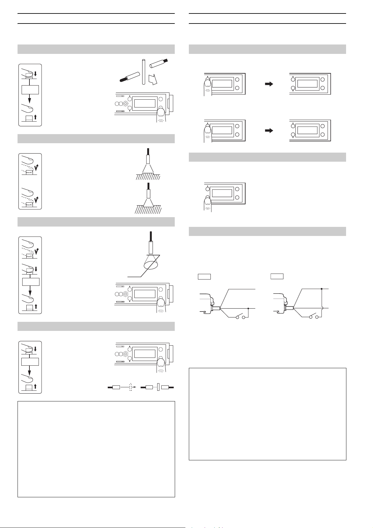
SETTING SENSITIVITY
Select the sensitivity setting procedure according to the target condition.
CHANGE THE SETTING VALUE
You can change the setting value in “excess gain display” mode or “setting value display” mode.
For sensitivity adjustment using a moving target
z Fully-automatic Calibration
1. Pass a target through the
optical axis while pressing the SET button.
At least
3 seconds
2. Confirm that the calibration indicator (yellow LED)
flashes.
3. Release the SET button.
AB
CH
# 2
MODE
SET
The calibration indicator
(yellow LED) goes off.
To detect a minute difference
z Two-point Calibration
1. With a target in place, press
the SET button and release it.
The calibration indicator (yellow LED) lights.
2. With the target removed,
press the SET button and
release it. The calibration
indicator (yellow LED) goes
off.
For target positioning
z Positioning Calibration
1. With no target, press the
SET button and release it.
The calibration indicator
(yellow LED) lights.
2. Place a target in the position where it is to be
At least
3 seconds
stopped.
3. Press the SET button until
the calibration indicator
flashes.
AB
CH
# 2
MODE
SET
4. Release the SET button.
For stable detection unaffected by dust
z Maximum Sensitivity Setting
1. Under the following con-
At least
3 seconds
ditions press the SET
button until the calibration
indicator (yellow LED)
flashes.
2. Release the SET button.
The calibration indicator
(yellow LED) goes off.
AB
Reflective type Thrubeam type
With no target With target
CH
# 2
CUE: When the sensitivity difference is insufficient
If sensitivity has no allowance after calibration, “------” flashes for 3
seconds on the LCD display monitor.
Note: Sensitivity is set and registered even when the sensitivity difference is insufficient. Be sure to confirm that detection is properly performed.
CUE: Locking the operation button (Key protect)
Hold down [MODE] and [UP] simultaneously for 3 seconds to lock the
operation button. When the operation button is locked, “Loc” is displayed in flashing letters.
To unlock the operation button, repeat the procedure above. “vnL”
(unlocked) is displayed in flashing letters.
Even when the operation button is locked, display data and channel
can be changed.
MODE
SET
Increase sensitivity (=Decrease the setting value)
z In excess gain display mode
The sensitivity increases by 1% each time you press [UP].
CH
# 2
MODE
SET
CH
# 2
MODE
SET
z In setting value display mode
The setting value decreases by 1 each time you press [DOWN].
CH
#
MODE
SET
CH
#
MODE
SET
Decrease sensitivity (=Increase the setting value)
The method for decreasing the sensitivity is the same as for increasing
the sensitivity, except you must press [DOWN] instead.
CH
# 2
MODE
SET
CUE: Holding down [UP] or [DOWN] changes the setting value rapidly.
For sensitivity adjustment using an external signal
z External Calibration Function
1. Hold down [MODE] and [UP] simultaneously for 3 seconds to display
“Loc”. (If “vnL” appears, repeat the same procedure.)
2. Connect the pink cable to a switch or PLC.
NPN
Brown
Blue
Pink
Contact or
solid-state input
The minimum input time is 20 ms.
3. The external calibration procedure is the same as using the SET button. Turn the input device on instead of pressing the SET button.
Also, turn the input device off instead of releasing the SET button.
(You can perform all the setting procedures described on the left.)
CUE: Calibration input during detection
You can re-adjust sensitivity during detection without stopping the
operation.
The sensor continues operation with the previous sensitivity setting
until sensitivity readjustment is completed.
CUE: External calibration with several units
When several units are connected, the sensitivity of all the FS-T2(P)
expansion units can be simultaneously set using the external calibration input through the FS-V1(P).
You can select a unit to be externally calibrated by setting its key protection switch to the LOCK position.
External calibration is effective for all the units which are locked. Set
the key protection switch to LOCK on the FS-T2(P) expansion unit to
be externally calibrated.
PNP
+V
0V
Brown
Blue
Pink
Contact or solid state input
+V
0V
2
Page 3

CONTROL AN EXPANSION UNIT [FS-T2(P)]
1. To change the channel, press
[UP] (or [DOWN]) while holding
[MODE].
Select the channel for the
expansion unit [FS-T2(P)] to be
controlled.
2. You can monitor the expansion
unit [FS-T2(P)] or change its
sensitivity setting value using
the same procedures as for the
FS-V1(P).
Channel
display
AB
CH
# 2
SET
MODE
CH2 CH17CH4CH3
Expansion units
CONNECTING FIBER UNIT
Lower the quick-release lever, insert the fiber unit about 14 mm until it
reaches the end, and then lift the quick-release lever.
12
• To connect a fiber unit with a small diameter, use the adaptor
included with the FU series.
1. Attach the adaptor to the fiber
unit.
2. Fully insert the adaptor into the
mounting holes of the amplifier,
and then lift the quick-release
lever.
1
2
• You cannot use the FS-V1(P)’s SET button to set the sensitivity of the
expansion unit.
• The red LED and green LED turn ON and OFF in response to the
expansion unit [FS-T2(P)] turning ON and OFF.
Note 1: You cannot control the [FS-M2(P)] (Manual calibration model).
Note 2: The channel for the [FS-M2(P)] is displayed as “------”. The
red LED and green LED turn ON and OFF in response to the [FSM2(P)] turning ON and OFF.
Note 3: If you add an FS-V20 Series expansion unit, you may not be
able to control the FS-V20 Series and any expansion units added after
the FS-V20 Series .
Note: If the fiber unit is improperly connected, the sensor cannot meet
the specifications.
• The required adaptor is included in each model of the FU series. If an
inadequate adaptor is used, the fiber unit cannot be properly installed.
Cable outer dia. Type Shape
φ1.3
φ1.0
Adaptor A
(OP-26500)
Adaptor B
(OP-26501)
• To connect the coaxial reflective type fiber unit to the amplifier, connect the single-core fiber to the transmitter side, and connect the
multiple-core fiber to the receiver side.
(Connect the fibers according to the marking on the amplifier lateral side.)
Transmitter
Multiple-core
Single-core
Receiver
MOUNTING MAIN UNIT
Mounting/Detaching the unit to/from a DIN rail or the
mounting bracket.
Hook the claw located at the unit cable side onto the DIN rail, and then hook the
front side claw to the rail while pressing the amplifier forward. To detach the
unit, unhook the front claw by lifting the unit front side while pressing it forward.
Mounting Detaching
MUTUAL INTERFERENCE SUPPRESSION FUNCTION
When using several fiber units, each fiber unit is free from light
interference from up to 4 adjacent fiber units.
When the fiber units are mounted closely, each fiber unit and its 4 adjacent units are designed to receive light at different pulse frequencies to
avoid interference.
MOUNTING EXPANSION UNITS
Mounting EXPANSION units
1. Detach the protective cover from the
unit’s side panel.
2. Mount units to a DIN rail one by one.
3. Slide one expansion unit toward
another. Align the front claws of the
units and push the unit together until
they click.
4. Fix the units together by pushing an
end unit onto each end. (The end units
are included in the expansion unit)
Detaching units from DIN rail
1. Remove the end units.
2. Slide the expansion units apart, and
detach them individually.
(Do not detach multiple units connected together with end units.)
• When several units are connected, confirm the ambient temperature. (See "Specifications" on P. 1.)
NOTICE
• To connect several units, be sure to use a DIN rail and end units.
• To mount or detach several units, be sure to turn the power off.
• Do not remove the protective cover of the expansion connector
on the outmost unit.
Mounting a unit laterally
Secure the screws through the mounting bracket’s side hole (accessory)
M3 screw
You can mount the FS-T(P) series and
the FS-M(P) series together within the
same system.
Note: If you do not use the expansionunits, the mutual interference suppress
function is not available.
Align the claw.
Expansion
Main unit
1.
Remove the protective cover.
2.
unit
Up to 16 expansion units
can be connected.
1. The FS-T1(P)/M1(P) can be used as the
same unit as well as the FS-V1(P).
2. FS-M2(P) can be used as the expansion unit
as well as the FS-T2(P).
The sticker shown on the right is
included in the expansion unit. Apply
this sticker near the sensor.
End unit
(Included
with FS-T2)
Slide the unit to the
right to remove it.
3
Page 4

SETTING 2 INDEPENDENT OUTPUTS
V
The FS-V1(P) allows you to set two types of sensitivity (tolerance individually.
To change the channel, press [UP] or [DOWN] while holding [MODE].
Output lines for channels A and B
CH
#
CH
Black
White
Channel A output
Channel B output
D
HINTS ON CORRECT USE
• To extend the cable length, use a cable with at least a 0.3 mm2
cross-section area. Limit the length of cable extension to no more
than 100 m. (To connect several units, contact Keyence for further
information.)
• If the amplifier cable is placed together with power lines or high voltage lines in the same conduit, detection error may occur due to noise
interference, or the sensor may be damaged. Isolate the amplifier
cable from these lines.
• When using a commercially available switching regulator, ground the
frame ground terminal and ground terminal.
• Do not use the FS series outdoors, or in a place where extraneous
light can enter the light receiving surface directly.
• During maximum sensitivity setting, the detecting distance may vary
due to the difference in characteristics of each unit.
• When the stability output is not used, cut the orange cable at the root
or connect it to the 0 V (“+” for PNP output model) terminal of the
power supply, in order to avoid contact with other cables.
• When the external calibration is not used, cut the pink cable at the
root or connect it to the “+” (“0 V” for PNP output model) terminal of
the power supply, in order to avoid contact with other cables.
DIMENSIONS
FS-V1(P)
18
(Maximum
when the
cover is
opened)
78
4
2.1
6.7
When the mounting bracket
[included in FS-V1(P)] is attached:
1.1
36.5
5
11.3
15
18.5
When several units are connected:
End unit
1.
618 6L
1. The FS-V1(P) is mounted in .
2. When using expansion units, be sure to use the end unit
(accessory to the expansions unit.)
DIN-rail mounting
1,1 6
(33)
28.5
12
min.
2 x φ3.4
8
φ3.9 5-core x
35.48.4
53.5
16
Brown/Blue: 0.34 mm
Black/White/Pink: 0.18 mm
Cable length: 2 m
135
max.
(12.5)
12
min.
Rear view of mounting
bracket
151815
29.4
2.
End unit
Unit: mm
2
2
2 x (4.4 x 3.4)
No. of units L
1
2
3
4
5
6
7
8
9
10
11
12
13
14
15
16
108
117
126
135
144
9
18
27
36
45
54
63
72
81
90
99
I/O CIRCUIT
FS-V1
Overcurrent
protection circuit
main circuit
Photoelectric sensor
Input circuit
(External calibration input circuit)
12 to 24 VDC
3.3 kΩ
11 kΩ
FS-V1P
Overcurrent
protection circuit
main circuit
Photoelectric sensor
Input circuit
(External calibration input circuit)
3.3 kΩ
11 kΩ
Brown
Black
(Control output)
White
(Control output)
Blue
Pink (External calibration input)
Pink
Contact or solid
state input
Brown
Black
White
Blue
Pink (External calibration input)
Pink
Contact or solid
state input
0 V
100mA max.
Load
100mA max.
Load
100mA max.
Load
100mA max.
Load
12 to 24 VDC
0
12 to 24 VDC
12 to 24 VDC
WARRANTY
KEYENCE products are strictly factory-inspected. However, in the event of a failure,
contact your nearest KEYENCE office with details of the failure.
1. WARRANTY PERIOD
The warranty period shall be for one year from the date that the product has been
delivered to the location specified by the purchaser.
2. WARRANTY SCOPE
(1) If a failure attributable to KEYENCE occurs within the above mentioned warranty
period, we will repair the product, free of charge. However, the following cases shall
be excluded from the warranty scope.
• Any failure resulting from improper conditions, improper environments, improper
handling, or improper usage other than described in the instruction manual, the
user’s manual, or the specifications specifically arranged between the purchaser
and KEYENCE.
• Any failure resulting from factors other than a defect of our product, such as the
purchaser’s equipment or the design of the purchaser’s software.
• Any failure resulting from modifications or repairs carried out by any person other
than KEYENCE staff.
• Any failure that can certainly be prevented when the expendable part(s) is
maintained or replaced correctly as described in the instruction manual, the
user’s manual, etc.
• Any failure caused by a factor that cannot be foreseen at a scientific/technical
level at the time when the product has been shipped from KEYENCE.
• Any disaster such as fire, earthquake, and flood, or any other external factor, such
as abnormal voltage, for which we are not liable.
(2) The warranty scope is limited to the extent set forth in item (1), and KEYENCE
assumes no liability for any purchaser’s secondary damage (damage of equipment,
loss of opportunities, loss of profits, etc.) or any other damage resulting from a
failure of our product.
3. PRODUCT APPLICABILITY
KEYENCE products are designed and manufactured as general-purpose products
for general industries.
Therefore, our products are not intended for the applications below and are not
applicable to them. If, however, the purchaser consults with us in advance regarding
the employment of our product, understands the specifications, ratings, and
performance of the product on their own responsibility, and takes necessary safety
measures, the product may be applied. In this case, the warranty scope shall be the
same as above.
• Facilities where the product may greatly affect human life or property, such as
nuclear power plants, aviation, railroads, ships, motor vehicles, or medical
equipment
• Public utilities such as electricity, gas, or water services
• Usage outdoors, under similar conditions or in similar environments
2010
11226E 1080-1 96M11226
4
 Loading...