

Page 1

AutoID System
Integrated Setup Software
AutoID Navigator
User's Manual
Page 2

Preface
This manual presents an outline of the AutoID System Integrated Setup Software AutoID Navigator,
and describes the functions and method of use of this software.
Read and thoroughly understand this manual before you start to use this software. Store this
manual in a safe place so that you can retrieve it whenever necessary.
■ Related Manuals
Read the following manuals when you use the AutoID Navigator.
If you require these manuals, contact your agent.
Type of Manual Description of Manual
RF-500
Installation Guide
RF-500
Installation/Connection Manual
RF-500
Operation Manual
AutoID Navigator
User's Manual
(PDF only)
N-410
User's Manual
BL-700 Series
BL-U1, BL-U2, N-42
User's Manual
BL-600 Series
User's Manual
BL-500 Series
User's Manual
BL-180 Series
User's Manual
SR-500 Series
User's Manual
This manual describes the functions and features of the RF-500 Series,
and presents installation examples.
This manual describes how to install and connect the RF-500 Series or
related devices, and how to operate these devices.
This manual describes operation of the various system component devices,
settings for operating these devices, and the commands
for performing
communications between the various devices.
This manual.
This manual describes how to operate and set up the AutoID system
integrated setup software AutoID Navigator.
This manual describes how to install and set up the RS-485 Master Unit
N-410, settings for operating the N-410, and how to operate devices.
This manual describes how to connect, install, and set the BL-700 Series
Long Range Laser Bar Code Reader and the BL-U1/BL-U2/N-42 Power
Supply Unit and includes precautions for usage.
This manual describes how to connect, install, and set the BL-600 Series
Super Compact Laser Bar Code Reader and includes precautions for
usage.
This manual describes how to connect, install, and set the BL-500 Series
Super Compact Laser Bar Code Reader and includes precautions for
usage.
This manual describes how to connect, install, and set the BL-180 Series
Super Compact CCD Bar Code Reader and includes precautions for
usage.
This manual describes how to connect, install, and set the SR-500 Series
Fixed 2D Code Reader and includes precautions for usage.
•Microsoft, Windows, Windows 2000, Windows XP are registered trademarks or trademarks
of Microsoft Corporation in the United States or other respective countries.
• CC-Link and MELSEC are registered trademarks of Mitsubishi Electric Corporation.
•DeviceNet is a registered trademark of ODVA (Open DeviceNet Vendor Association, Inc.).
• SYSMAC is a registered trademark of OMRON Corporation.
Page 3

For Safe Usage
This manual describes handling, operation, and safety information for AutoID Navigator.
Read this manual thoroughly in order to take full advantage of product performance, and use the
product only after fully understanding its contents.
Store this manual in a safe place so that you can retrieve it whenever necessary.
See to it that the manual reaches the last person who is going to use the product.
■ This manual's format
This manual uses the following symbols to alert you to important information.
Important
Note
Tip
DANGER
WARNING
CAUTION
Failure to follow these instructions may lead to death or serious injury.
Failure to follow these instructions may lead to injury.
Failure to follow these instructions may lead to physical damage (product
malfunction, etc.).
This heading is used to indicate precautions and restrictions that must be followed when operating the product.
This heading is used to indicate cautions relating to device operation where
operator error is likely.
Indicates useful information or information that aids understanding of text descriptions.
Indicates a reference item or page to be referred to in this manual and a separate manual.
1
Page 4

■ General Precautions
•Verify that this device is operating normally in terms of functionality and performance before the
start of work and when operating this device.
•We recommend that you take substantial safety measures to avoid any damage in the event
that a problem occurs.
•Proceed with care when modifying this product, or when using it in a manner that falls outside of
the ranges indicated in its specifications, since KEYENCE is unable to guarantee device functionality or performance in such situations.
•Use this product in combination with other devices only after careful consideration, since it may
fail to satisfy its functionality and performance capabilities as a result of the conditions and environment in which it is used.
•Do not use the product with the purpose of protecting human beings.
■ Requests
When using this device under the following conditions or operating environments, please consult
with your KEYENCE sales representative in addition to implementing safety measures such as
product operation that allows leeway with respect to features and use of failsafe provisions.
•Use of the product under conditions not described in this manual
•Use of the product in nuclear power generation control, railroad facilities, aviation facilities,
vehicles, combustion devices, medical equipment, entertainment machinery, safety equipment,
etc.
•Use of the product in applications that may have a significant impact on human life or property,
or that place a high priority on safety
2
Page 5

Software License Agreement
Before you use this software, be sure to read the terms of this agreement.
Once you have started to use this software, it is assumed that you have consented to these
terms, and an agreement is established between KEYENCE CORPORATION and the user.
Terms
1. Rights of Use
KEYENCE CORPORATION shall permit the user the non-exclusive rights to use this software
in accordance with the terms of this agreement.
2. Copyright
Copyright relating to this software and manual shall belong to KEYENCE CORPORATION,
and the user shall not have rights other than the rights of use.
3. Forbidden Items
The user shall not be able to copy this software, nor be able to sell or distribute it to a third
party. The user, however, shall be able to copy this software for the purpose of making backups
for the user's own use.
4. Exemption of Liabilities
KEYENCE CORPORATION shall not be subject to liability with respect to damage on the part
of the user or a third party as a result of having operated this software.
5. Cancellation of Agreement
Should the user have violated any terms of this agreement, KEYENCE CORPORATION shall
immediately be able to cancel this agreement, and the user shall destroy or return this software and copies to KEYENCE CORPORATION.
3
Page 6

Contents
Preface
Contents . . . . . . . . . . . . . . . . . . . . . . . . . . . . . . . . . . . . . . . . . . . . . . . . . . . . . . . . . . . . . . . . . . 4
Conventions Used In This Manual . . . . . . . . . . . . . . . . . . . . . . . . . . . . . . . . . . . . . . . . . . . . . 7
Te r m i n o lo g y . . . . . . . . . . . . . . . . . . . . . . . . . . . . . . . . . . . . . . . . . . . . . . . . . . . . . . . . . . . . . . 7
Chapter 1 BEFORE YOU START USING AutoID Navigator
1-1 Checking the Contents of the Package . . . . . . . . . . . . . . . . . . . . . . . . . . . . . . . . . . 1-2
1-2 Operating Environment and System Configuration . . . . . . . . . . . . . . . . . . . . . . . . 1-3
Operating Environment and System Configuration . . . . . . . . . . . . . . . . . . . . . . . . . . . . . . .1-3
Functions and Features . . . . . . . . . . . . . . . . . . . . . . . . . . . . . . . . . . . . . . . . . . . . . . . . . . . .1-4
1-3 Installing AutoID Navigator . . . . . . . . . . . . . . . . . . . . . . . . . . . . . . . . . . . . . . . . . . . . 1-5
Before Installation . . . . . . . . . . . . . . . . . . . . . . . . . . . . . . . . . . . . . . . . . . . . . . . . . . . . . . . .1-5
Installing AutoID Navigator . . . . . . . . . . . . . . . . . . . . . . . . . . . . . . . . . . . . . . . . . . . . . . . . .1-6
Uninstalling AutoID Navigator . . . . . . . . . . . . . . . . . . . . . . . . . . . . . . . . . . . . . . . . . . . . . . .1-9
1-4 Data Compatibility . . . . . . . . . . . . . . . . . . . . . . . . . . . . . . . . . . . . . . . . . . . . . . . . . . .1-11
Compatibility between Setup Files . . . . . . . . . . . . . . . . . . . . . . . . . . . . . . . . . . . . . . . . . . 1-11
Chapter 2 OUTLINE OF AutoID Navigator
2-1 Starting Up and Quitting AutoID Navigator . . . . . . . . . . . . . . . . . . . . . . . . . . . . . . . 2-2
How to Startup AutoID Navigator. . . . . . . . . . . . . . . . . . . . . . . . . . . . . . . . . . . . . . . . . . . . .2-2
How to Quit AutoID Navigator . . . . . . . . . . . . . . . . . . . . . . . . . . . . . . . . . . . . . . . . . . . . . . .2-2
Option Settings . . . . . . . . . . . . . . . . . . . . . . . . . . . . . . . . . . . . . . . . . . . . . . . . . . . . . . . . . .2-3
2-2 Names and Functions of Screen Parts. . . . . . . . . . . . . . . . . . . . . . . . . . . . . . . . . . . 2-4
About screens . . . . . . . . . . . . . . . . . . . . . . . . . . . . . . . . . . . . . . . . . . . . . . . . . . . . . . . . . . .2-4
2-3 Registerable Devices . . . . . . . . . . . . . . . . . . . . . . . . . . . . . . . . . . . . . . . . . . . . . . . . . 2-7
Registerable Devices. . . . . . . . . . . . . . . . . . . . . . . . . . . . . . . . . . . . . . . . . . . . . . . . . . . . . .2-7
2-4 List of Functions. . . . . . . . . . . . . . . . . . . . . . . . . . . . . . . . . . . . . . . . . . . . . . . . . . . . . 2-9
Basic Project File Functions . . . . . . . . . . . . . . . . . . . . . . . . . . . . . . . . . . . . . . . . . . . . . . . .2-9
Setup File Management Functions . . . . . . . . . . . . . . . . . . . . . . . . . . . . . . . . . . . . . . . . . . .2-9
Device Add/Delete Functions . . . . . . . . . . . . . . . . . . . . . . . . . . . . . . . . . . . . . . . . . . . . . .2-10
Chapter 3 MANAGING PROJECTS
3-1 Outline of Projects . . . . . . . . . . . . . . . . . . . . . . . . . . . . . . . . . . . . . . . . . . . . . . . . . . . 3-2
What Is a "Project"?. . . . . . . . . . . . . . . . . . . . . . . . . . . . . . . . . . . . . . . . . . . . . . . . . . . . . . .3-2
3-2 Creating Projects . . . . . . . . . . . . . . . . . . . . . . . . . . . . . . . . . . . . . . . . . . . . . . . . . . . . 3-3
Procedure for Creating a Project . . . . . . . . . . . . . . . . . . . . . . . . . . . . . . . . . . . . . . . . . . . . .3-3
3-3 Registering Devices and Saving Projects . . . . . . . . . . . . . . . . . . . . . . . . . . . . . . . . 3-4
Signal Registration and Network Registration . . . . . . . . . . . . . . . . . . . . . . . . . . . . . . . . . . .3-4
Registering Devices by Single Registration. . . . . . . . . . . . . . . . . . . . . . . . . . . . . . . . . . . . . 3-5
Registering Devices by Network Registration . . . . . . . . . . . . . . . . . . . . . . . . . . . . . . . . . . .3-6
Saving Projects . . . . . . . . . . . . . . . . . . . . . . . . . . . . . . . . . . . . . . . . . . . . . . . . . . . . . . . . . .3-9
Opening Projects . . . . . . . . . . . . . . . . . . . . . . . . . . . . . . . . . . . . . . . . . . . . . . . . . . . . . . . .3-10
Creating a New Project . . . . . . . . . . . . . . . . . . . . . . . . . . . . . . . . . . . . . . . . . . . . . . . . . . .3-10
4
Page 7

3-4 Editing Setup Files . . . . . . . . . . . . . . . . . . . . . . . . . . . . . . . . . . . . . . . . . . . . . . . . . . .3-11
Type of and Brief Description of Setup Files . . . . . . . . . . . . . . . . . . . . . . . . . . . . . . . . . . . 3-11
How to Set Parameters . . . . . . . . . . . . . . . . . . . . . . . . . . . . . . . . . . . . . . . . . . . . . . . . . . .3-13
Saving Setup Files. . . . . . . . . . . . . . . . . . . . . . . . . . . . . . . . . . . . . . . . . . . . . . . . . . . . . . .3-14
Opening Setup Files . . . . . . . . . . . . . . . . . . . . . . . . . . . . . . . . . . . . . . . . . . . . . . . . . . . . .3-14
Initializing Setup Files . . . . . . . . . . . . . . . . . . . . . . . . . . . . . . . . . . . . . . . . . . . . . . . . . . . .3-14
Sending/Receiving Parameters . . . . . . . . . . . . . . . . . . . . . . . . . . . . . . . . . . . . . . . . . . . . .3-15
Chapter 4 SETTING DEVICE OPERATIONS
4-1 Setting IC Tags . . . . . . . . . . . . . . . . . . . . . . . . . . . . . . . . . . . . . . . . . . . . . . . . . . . . . . 4-2
Setting the Memory Map . . . . . . . . . . . . . . . . . . . . . . . . . . . . . . . . . . . . . . . . . . . . . . . . . . .4-2
Memo. . . . . . . . . . . . . . . . . . . . . . . . . . . . . . . . . . . . . . . . . . . . . . . . . . . . . . . . . . . . . . . . . .4-3
Memory Dump. . . . . . . . . . . . . . . . . . . . . . . . . . . . . . . . . . . . . . . . . . . . . . . . . . . . . . . . . . .4-4
4-2 RF-500 Series Settings. . . . . . . . . . . . . . . . . . . . . . . . . . . . . . . . . . . . . . . . . . . . . . . . 4-5
Parameters to be Set. . . . . . . . . . . . . . . . . . . . . . . . . . . . . . . . . . . . . . . . . . . . . . . . . . . . . .4-5
Act Setting . . . . . . . . . . . . . . . . . . . . . . . . . . . . . . . . . . . . . . . . . . . . . . . . . . . . . . . . . . . . . .4-6
RFID Communication Setting . . . . . . . . . . . . . . . . . . . . . . . . . . . . . . . . . . . . . . . . . . . . . . .4-7
Output Data Setting . . . . . . . . . . . . . . . . . . . . . . . . . . . . . . . . . . . . . . . . . . . . . . . . . . . . . . .4-9
RS-232C Port Setting . . . . . . . . . . . . . . . . . . . . . . . . . . . . . . . . . . . . . . . . . . . . . . . . . . . .4-10
4-3 BL Series Settings . . . . . . . . . . . . . . . . . . . . . . . . . . . . . . . . . . . . . . . . . . . . . . . . . . .4-11
Parameters to be Set. . . . . . . . . . . . . . . . . . . . . . . . . . . . . . . . . . . . . . . . . . . . . . . . . . . . . 4-11
Act Setting . . . . . . . . . . . . . . . . . . . . . . . . . . . . . . . . . . . . . . . . . . . . . . . . . . . . . . . . . . . . .4-12
Barcode Setting . . . . . . . . . . . . . . . . . . . . . . . . . . . . . . . . . . . . . . . . . . . . . . . . . . . . . . . . .4-14
Port Setting (in case of BL-180 /500 /600 /700 ) . . . . . . . . . . . . . . . . . . . . . . . . . . . . . . . .4-15
Other Settings . . . . . . . . . . . . . . . . . . . . . . . . . . . . . . . . . . . . . . . . . . . . . . . . . . . . . . . . . .4-17
4-4 SR-500 Series Settings . . . . . . . . . . . . . . . . . . . . . . . . . . . . . . . . . . . . . . . . . . . . . . 4-18
Parameters to be Set. . . . . . . . . . . . . . . . . . . . . . . . . . . . . . . . . . . . . . . . . . . . . . . . . . . . .4-18
Act Setting . . . . . . . . . . . . . . . . . . . . . . . . . . . . . . . . . . . . . . . . . . . . . . . . . . . . . . . . . . . . .4-19
Code Setting . . . . . . . . . . . . . . . . . . . . . . . . . . . . . . . . . . . . . . . . . . . . . . . . . . . . . . . . . . .4-20
Camera Setting . . . . . . . . . . . . . . . . . . . . . . . . . . . . . . . . . . . . . . . . . . . . . . . . . . . . . . . . .4-21
Timing Setting . . . . . . . . . . . . . . . . . . . . . . . . . . . . . . . . . . . . . . . . . . . . . . . . . . . . . . . . . .4-22
Port Setting . . . . . . . . . . . . . . . . . . . . . . . . . . . . . . . . . . . . . . . . . . . . . . . . . . . . . . . . . . . .4-23
Other Settings . . . . . . . . . . . . . . . . . . . . . . . . . . . . . . . . . . . . . . . . . . . . . . . . . . . . . . . . . .4-24
4-5 RS-485 Controller (NX-50RS) Settings . . . . . . . . . . . . . . . . . . . . . . . . . . . . . . . . . . 4-25
Parameters to be Set. . . . . . . . . . . . . . . . . . . . . . . . . . . . . . . . . . . . . . . . . . . . . . . . . . . . .4-25
RS-232C (modular) Setting . . . . . . . . . . . . . . . . . . . . . . . . . . . . . . . . . . . . . . . . . . . . . . . . 4-26
Head Setting . . . . . . . . . . . . . . . . . . . . . . . . . . . . . . . . . . . . . . . . . . . . . . . . . . . . . . . . . . .4-27
Te r m i n a l S e t t ing . . . . . . . . . . . . . . . . . . . . . . . . . . . . . . . . . . . . . . . . . . . . . . . . . . . . . . . . .4-28
RS-485 Setting . . . . . . . . . . . . . . . . . . . . . . . . . . . . . . . . . . . . . . . . . . . . . . . . . . . . . . . . .4-29
4-6 CC-Link Controller (NX-50CL) Settings . . . . . . . . . . . . . . . . . . . . . . . . . . . . . . . . . 4-30
Parameters to be Set. . . . . . . . . . . . . . . . . . . . . . . . . . . . . . . . . . . . . . . . . . . . . . . . . . . . .4-30
RS-232C (modular) Setting . . . . . . . . . . . . . . . . . . . . . . . . . . . . . . . . . . . . . . . . . . . . . . . . 4-31
Head Setting . . . . . . . . . . . . . . . . . . . . . . . . . . . . . . . . . . . . . . . . . . . . . . . . . . . . . . . . . . .4-32
Te r m i n a l S e t t ing . . . . . . . . . . . . . . . . . . . . . . . . . . . . . . . . . . . . . . . . . . . . . . . . . . . . . . . . .4-33
CC-Link Setting . . . . . . . . . . . . . . . . . . . . . . . . . . . . . . . . . . . . . . . . . . . . . . . . . . . . . . . . .4-34
5
Page 8

4-7 DeviceNet Controller (NX-50DN) Settings . . . . . . . . . . . . . . . . . . . . . . . . . . . . . . . 4-35
Parameters to be Set. . . . . . . . . . . . . . . . . . . . . . . . . . . . . . . . . . . . . . . . . . . . . . . . . . . . .4-35
RS-232C (modular) Setting . . . . . . . . . . . . . . . . . . . . . . . . . . . . . . . . . . . . . . . . . . . . . . . .4-36
Head Setting . . . . . . . . . . . . . . . . . . . . . . . . . . . . . . . . . . . . . . . . . . . . . . . . . . . . . . . . . . .4-37
Te r m i n a l S e t t ing . . . . . . . . . . . . . . . . . . . . . . . . . . . . . . . . . . . . . . . . . . . . . . . . . . . . . . . . .4-38
DeviceNet Setting . . . . . . . . . . . . . . . . . . . . . . . . . . . . . . . . . . . . . . . . . . . . . . . . . . . . . . .4-39
4-8 RS-485 Master Unit (N-410) Settings . . . . . . . . . . . . . . . . . . . . . . . . . . . . . . . . . . . 4-40
Parameters to be Set. . . . . . . . . . . . . . . . . . . . . . . . . . . . . . . . . . . . . . . . . . . . . . . . . . . . .4-40
Main Setting. . . . . . . . . . . . . . . . . . . . . . . . . . . . . . . . . . . . . . . . . . . . . . . . . . . . . . . . . . . .4-41
Slave Setting . . . . . . . . . . . . . . . . . . . . . . . . . . . . . . . . . . . . . . . . . . . . . . . . . . . . . . . . . . .4-42
Protocol Setting . . . . . . . . . . . . . . . . . . . . . . . . . . . . . . . . . . . . . . . . . . . . . . . . . . . . . . . . .4-43
RS-232C Setting . . . . . . . . . . . . . . . . . . . . . . . . . . . . . . . . . . . . . . . . . . . . . . . . . . . . . . . .4-45
RS-485 Setting . . . . . . . . . . . . . . . . . . . . . . . . . . . . . . . . . . . . . . . . . . . . . . . . . . . . . . . . .4-46
Chapter 5 OTHER SETTINGS AND OPERATIONS
5-1 Settings Macros . . . . . . . . . . . . . . . . . . . . . . . . . . . . . . . . . . . . . . . . . . . . . . . . . . . . . 5-2
Macros and Active Macros . . . . . . . . . . . . . . . . . . . . . . . . . . . . . . . . . . . . . . . . . . . . . . . . .5-2
5-2 Setting Macro Operations . . . . . . . . . . . . . . . . . . . . . . . . . . . . . . . . . . . . . . . . . . . . . 5-3
Setting Macro Operations . . . . . . . . . . . . . . . . . . . . . . . . . . . . . . . . . . . . . . . . . . . . . . . . . . 5-3
Act Setting . . . . . . . . . . . . . . . . . . . . . . . . . . . . . . . . . . . . . . . . . . . . . . . . . . . . . . . . . . . . . .5-4
Macro Test. . . . . . . . . . . . . . . . . . . . . . . . . . . . . . . . . . . . . . . . . . . . . . . . . . . . . . . . . . . . . .5-5
5-3 Quick Calibration Operation . . . . . . . . . . . . . . . . . . . . . . . . . . . . . . . . . . . . . . . . . . . 5-6
Code Specification Check . . . . . . . . . . . . . . . . . . . . . . . . . . . . . . . . . . . . . . . . . . . . . . . . . .5-6
Code Setting . . . . . . . . . . . . . . . . . . . . . . . . . . . . . . . . . . . . . . . . . . . . . . . . . . . . . . . . . . . .5-7
Camera Setting . . . . . . . . . . . . . . . . . . . . . . . . . . . . . . . . . . . . . . . . . . . . . . . . . . . . . . . . . .5-8
5-4 Creating a Quick Setup Code . . . . . . . . . . . . . . . . . . . . . . . . . . . . . . . . . . . . . . . . . . 5-9
Chapter 6 TEST FUNCTIONS
6-1 Terminal Function. . . . . . . . . . . . . . . . . . . . . . . . . . . . . . . . . . . . . . . . . . . . . . . . . . . . 6-2
Te r m i n a l F u nc tion Screen . . . . . . . . . . . . . . . . . . . . . . . . . . . . . . . . . . . . . . . . . . . . . . . . . .6-2
6-2 Test Function . . . . . . . . . . . . . . . . . . . . . . . . . . . . . . . . . . . . . . . . . . . . . . . . . . . . . . . 6-3
Te s t Function Screen. . . . . . . . . . . . . . . . . . . . . . . . . . . . . . . . . . . . . . . . . . . . . . . . . . . . . .6-3
6-3 View Image Function . . . . . . . . . . . . . . . . . . . . . . . . . . . . . . . . . . . . . . . . . . . . . . . . . 6-4
View image function screen. . . . . . . . . . . . . . . . . . . . . . . . . . . . . . . . . . . . . . . . . . . . . . . . .6-4
Chapter A APPENDIX
1 Index . . . . . . . . . . . . . . . . . . . . . . . . . . . . . . . . . . . . . . . . . . . . . . . . . . . . . . . . . . . . . . . . A-2
6
Page 9

Conventions Used In This Manual
Terminology
This manual uses the following terminology excluding some instances.
Ter m Description
Head Refers to the RF Series, BL Series, or SR Series.
RF Series Refers to the RF Series RFID system.
BL Series Refers to the BL Series bar code readers.
SR Series Refers to the SR Series 2D code readers.
IC tag Generic name for the IC tags which are supported by the RF-500 Series.
Coin-shaped IC tag Refers to the RF-T5P10 (coin-shaped IC tag).
Small IC tag Refers to the RF-T5F20 (small IC tag).
Standard IC tag Refers to the RF-T5F30 (standard IC tag).
Network controller Generic name for the NX-50 Series which relays a head to/from a field network.
RS-485 controller Refers to the NX-50RS (a network controller supporting RS-485).
CC-Link controller Refers to the NX-50CL (a network controller supporting CC-Link).
DeviceNet controller Refers to the NX-50DN (a network controller supporting DeviceNet).
RS-485 master unit Refers to the N-410 (RS-485 master unit).
AutoID Navigator
Integrated program for controlling and configuring all devices used with the RF500 Series.
7
Page 10

MEMO
8
Page 11

1
BEFORE YOU START
USING AutoID Navigator
This chapter describes the contents of the package, basic functions and
operating environment of AutoID Navigator, and how to install AutoID
Navigator.
1-1 Checking the Contents of the Package . . . . . . . . . . 1-2
1-2 Operating Environment and System Configuration . 1-3
1-3 Installing AutoID Navigator. . . . . . . . . . . . . . . . . . . . 1-5
1-4 Data Compatibility . . . . . . . . . . . . . . . . . . . . . . . . . .1-11
1-1
Page 12

1-1
Checking the Contents of the Package
1
The package contains the following disk.
BEFORE YOU START USING AutoID Navigator
Before you start using AutoID Navigator, make sure that the package contains this disk.
Master Disk (CD-ROM) ... 1 disk
■ Contents of CD-ROM
AutoID Navigator (Japanese, English)
PDF manual (Japanese, English)
AutoID Navigator User’s Manual
RF-500 Series Operation Manual
RF-500 Series Installation and Connection Manual
NX-50 Series Operation Manual
1-2
Page 13

1-2
Operating Environment and System Configuration
This section describes the operating environment, system configuration, features and functions of
AutoID Navigator.
Be sure to read this section before using AutoID Navigator.
Operating Environment and System Configuration
The following environment is required to run the AutoID System Integrated Setup Software
AutoID Navigator.
Make sure that the system you are using satisfies the following conditions and that all of the
required hardware is present.
Item Description
OS
CPU PentiumIII 600MHz or more
Memory 128MB or more
Hard disk 400MB or more
CD-ROM drive Required for installation
RS-232C port
Windows XP (SP1 or later)
Windows 2000 (SP2 or later)
D-Sub 9-pin RS-232C port
This is required to communicate with an NX Series (network controller),
N-410 (RS-485 master unit) and BL-U1/U2 (dedicated power supply unit).
1
BEFORE YOU START USING AutoID Navigator
1-3
Page 14

1-2 Operating Environment and System Configuration
1
Functions and Features
BEFORE YOU START USING AutoID Navigator
AutoID Navigator is integrated setup software for editing and setting up AutoID devices, such as
RFID systems, barcode readers, and 2D code readers on Windows. This software allows you to
batch-manage the complex settings of system component devices in an easy-to-understand manner.
■ Parameter setup function
Setup parameters for AutoID system devices can be set, sent to and read from devices so that they
can be loaded and managed as setup files.
AutoID Navigator allows you to set and manage the following Keyence AutoID devices:
•RFID system RF-500 Series
•Barcode reader BL Series
•2D code reader SR-500 Series
•Network controller NX-50 Series
•RS-485 master unit N-410
■ Terminal function
This function allows you to send commands so that you can simply check operation of connected
devices. Also, responses to commands can also be collected and saved as a log.
■ Test function
This function allows you to test the operation status or communications status of the connected
devices.
Var i o u s t e st modes are available according to the connecting device.
For details about the test mode, refer to the User’s Manual.
■ Print function, file output function
This function allows you to print the settings of each device configured with AutoID Navigator, or
output the history data collected with the terminal function or test function in the CSV format.
1-4
Page 15

1-3 Installing AutoID Navigator
This section describes how to install AutoID Navigator on your personal computer's hard disk.
Before Installation
Check the following before you start to install AutoID Navigator.
Note
We recommend making a backup of the master disk in the event of it becoming
damaged, for example.
■ Windows environment and installation media
AutoID Navigator is software that runs on Windows XP or Windows 2000.
Make sure that Windows XP or Windows 2000 is installed and running normally on the personal
computer you are using.
■ Free space on hard disk
AutoID Navigator can be installed on hard disk.
At least 400 Mbytes of free space is needed on the hard disk where AutoID Navigator is to be
installed.
1
BEFORE YOU START USING AutoID Navigator
1-5
Page 16

1-3 Installing AutoID Navigator
1
Installing AutoID Navigator
BEFORE YOU START USING AutoID Navigator
The following describes how to install AutoID Navigator to Windows XP at the following drive configuration:
C drive: hard disk drive
E drive: CD-ROM drive
1 Tur n y our personal computer ON and start up Windows.
Note
•When installing AutoID Navigator, log on as Administrator or a user having
rights such as a computer administrator who is permitted to change the system settings.
•Before starting installation, quit all other applications. Installation may take
longer if anti-virus software is running.
2 Insert the "AutoID Navigator master disk" into the CD-ROM drive of the personal computer.
3 Open the CD-ROM from Explorer, for example, and double-click "Setup_en.exe" in the root
folder.
4 Click the "Next" button.
The [Select Destination Folder] window is displayed.
Tip
To change the installation directory, click the "Browse" button and change the directory.
1-6
Page 17

1-3 Installing AutoID Navigator
5 Click the "Next" button.
The [Select Program Folder] window is displayed.
6 Click the "Next" button.
The [Create Shortcut] window is displayed.
1
BEFORE YOU START USING AutoID Navigator
7 Click the "Next" button.
The [Check the Installation information] window is displayed.
1-7
Page 18

1-3 Installing AutoID Navigator
1
8 Click the "Next" button.
BEFORE YOU START USING AutoID Navigator
9 If the message [The destination folder does not exist. Do you want to create it?] is dis-
played, click the "Yes" button.
The [Congratulations!] window is displayed.
10
Click the "Finish" button.
This completes installation of AutoID Navigator.
1-8
Page 19

1-3 Installing AutoID Navigator
Uninstalling AutoID Navigator
The following describes how to uninstall AutoID Navigator from a personal computer running WindowsXP.
1 Tur n y our personal computer ON and start up Windows.
Note
When uninstalling AutoID Navigator, log on as Administrator or a user having
rights such as a computer administrator who is permitted to change the system
settings.
2 Select {Start} - {Control Panel(C)} in that order.
The [Control Panel] window is displayed.
3 Double-click the "Add or Remove Programs" icon.
The [Add or Remove Programs] dialog box is displayed.
4 Select "AutoID Navigator" and click the "Remove" button.
1
BEFORE YOU START USING AutoID Navigator
5 The program delete confirmation screen is displayed. Click the "Next" button.
The [Uninstallation] window is displayed.
1-9
Page 20

1-3 Installing AutoID Navigator
1
6 Click the "Yes" button.
BEFORE YOU START USING AutoID Navigator
The [Finished Uninstallation] window is displayed.
7 Click the "Finish" button.
This completes uninstallation of AutoID Navigator.
1-10
Page 21

1-4 Data Compatibility
The following describes data compatibility.
Compatibility between Setup Files
AutoID Navigator does not support the reading of setup files made on the following setup software:
•Barcode Reader BL Series Setup Software
•Multi-drop Link Unit N-400 Setup Software
Also, setup files made on the AutoID Navigator are not compatible with setup files made on the
above setup software.
Note
•N-410 settings cannot be made on N-400 Setup Software.
•N-400 settings cannot be made on AutoID Navigator. When using N-400, use
the existing N-400 Setup Software.
•When changing the settings of a BL Series used on an existing system, set the
device settings again on AutoID Navigator for use.
1
BEFORE YOU START USING AutoID Navigator
1-11
Page 22

1-4 Data Compatibility
1
MEMO
BEFORE YOU START USING AutoID Navigator
1-12
Page 23

2
OUTLINE OF AutoID
Navigator
This chapter describes basic operations in AutoID Navigator, screens, devices
that can be registered, and how to create projects.
2-1 Starting Up and Quitting AutoID Navigator. . . . . . . . 2-2
2-2 Names and Functions of Screen Parts. . . . . . . . . . . 2-4
2-3 Registerable Devices . . . . . . . . . . . . . . . . . . . . . . . . 2-7
2-4 List of Functions . . . . . . . . . . . . . . . . . . . . . . . . . . . . 2-9
2-1
Page 24

2
2-1
This section describes how to start up and quit AutoID Navigator.
OUTLINE OF AutoID Navigator
How to Startup AutoID Navigator
Start up AutoID Navigator.
Starting Up and Quitting AutoID Navigator
1 Select {Programs(P)} → {KEYENCE Applications} → {AutoID Navigator} in that order from
the Start menu, or double-click on the desktop screen.
This starts up AutoID Navigator.
How to Quit AutoID Navigator
Quit AutoID Navigator.
1 Click the button on the right edge of the title bar.
This quits AutoID Navigator.
Different Procedure
2-2
Press the + keys.
Page 25

Option Settings
2-1 Starting Up and Quitting AutoID Navigator
The following describes the option settings on AutoID Navigator.
With the option settings, set the COM port and communications parameters that are used for
communicating between AutoID devices and the personal computer where AutoID Navigator is
installed.
1 Start up AutoID Navigator and click .
2 Select the COM port (RS-232C) on the personal computer and click the "OK" button.
2
OUTLINE OF AutoID Navigator
Note
•When "Manual" is selected as the connection method, select parameters
matched to the devices to be connected.
•When connecting the DV-90 Series using its USB port, select "DV-90 PC
Direct". Also, be sure to set the DV-90 Series to the direct communication
mode.
2-3
Page 26

2
2-2
The following describes the names and functions of parts in AutoID Navigator screens.
OUTLINE OF AutoID Navigator
About screens
The following screen is displayed when AutoID Navigator is started up.
Names and Functions of Screen Parts
(6) "Terminal" button
(1)Menu icons
(2) Display settings
tab
(3) Select configura-
tion menu
(4) Selection area
(5) Registration/setting area
Name Functions
(1) Menu icons
(2) Display settings tab This tab switches the display between "Project" or "Unit". 2-5
(3) Select configuration
menu
(4) Selection area This area displays details that can be set on tabs. 2-6
(5) Registration/setting
area
(6) "Terminal" button
(7) "Test mode" button
(8) "View image" button This button is used to obtain images with the SR-500 Series. 6-4
These icons are for managing (creating new, saving and reading) project
files, setting options, and updating the connection to devices.
This menu switches display of the project display area between "system
configuration" and "file constitution".
This area changes the selection of devices to register and the device
settings.
This button sends commands to the connected device, and displays the
terminal screen for verification of data that is read.
This button displays the test mode screen for testing the communication
status between the head and the IC tag, code reader reading status and
other information.
(8) "View image" button(7) "Test mode" button
See Page
2-9
2-6
2-7
6-2
6-3
2-4
Page 27

2-2 Names and Functions of Screen Parts
■ Project display and Unit display
AutoID Navigator is provided with two display modes for registered devices and setup files,
Project display and Unit display.
When Project display is selected, the device configuration registered to the project is displayed, and when Unit display is selected, information is displayed according to each
device type.
Switching between Project display and Unit display is performed by the [Project] and [Unit] tabs,
respectively.
Project display
2
OUTLINE OF AutoID Navigator
Click the tabs to switch between
display modes.
Display Tab Features
The device configuration registered to the project is displayed.
Project
Unit
Parameters can be set up and managed by each currently registered device.
When no devices are registered to the project, only the project name is
displayed.
Devices that can be registered by AutoID Navigator are displayed by device type.
This feature is useful to batch-set parameters for a particular device type.
However, the settings cannot be sent to or received from the devices connected
via the NX-50 Series or the N-410 Series.
Display by project configuration
Unit display
Display by device type
2-5
Page 28

2
2-2 Names and Functions of Screen Parts
■ System configuration and File constitution
["System configuration" and "File constitution" are indicated on the [Project] tab. "System configuration" hierarchically displays the devices registered to the project, and "File constitution" displays
device setup files divided into type groups.
OUTLINE OF AutoID Navigator
System configuration
Click to select the configuration
to be displayed from the list.
Display Configuration
The system configuration for the project is displayed hierarchically by individual
System configuration
File constitution
network.
This allows you to set devices while visually grasping the structure of the project.
The configuration of the project is displayed hierarchically by file type.
Files can be managed displayed by type (setup parameters, memory map and
macros).
The file name is indicated inside the brackets [ ], and files that are not yet saved
during editing or after a change are suffixed with "*".
Setup files whose checkbox is marked in the file constitution display can be printed
by the "Print" button at the bottom of the screen. Memory maps can be output as a
CSV format file by the "Save Tag Map" button.
Devices displayed hierarchically
by component device
File constitution
Setup files displayed hierarchically
by type group
Features
2-6
Page 29

2-3 Registerable Devices
This section describes the devices that can be registered to projects by AutoID Navigator.
Registerable Devices
The following devices can be registered and set on AutoID Navigator.
■ Masters
2
OUTLINE OF AutoID Navigator
Icon Device Description
N-410 Master unit made by Keyence for connecting by the RS-485 interface 4-33
Master unit This master unit supports CC-Link or DeviceNet. –
■ Controllers
Icon Device Description
NX-50RS This network controller supports the RS-485 link. 4-18
NX-50CL This network controller supports the CC-Link connection. 4-23
NX-50DN This network controller supports the DeviceNet connection. 4-28
■ RFID head
See Page
See Page
Icon Device Description
RF-500
This is the head of the RF-500 Series to which macros can be
registered.
See Page
4-5
2-7
Page 30
2-3 Registerable Devices
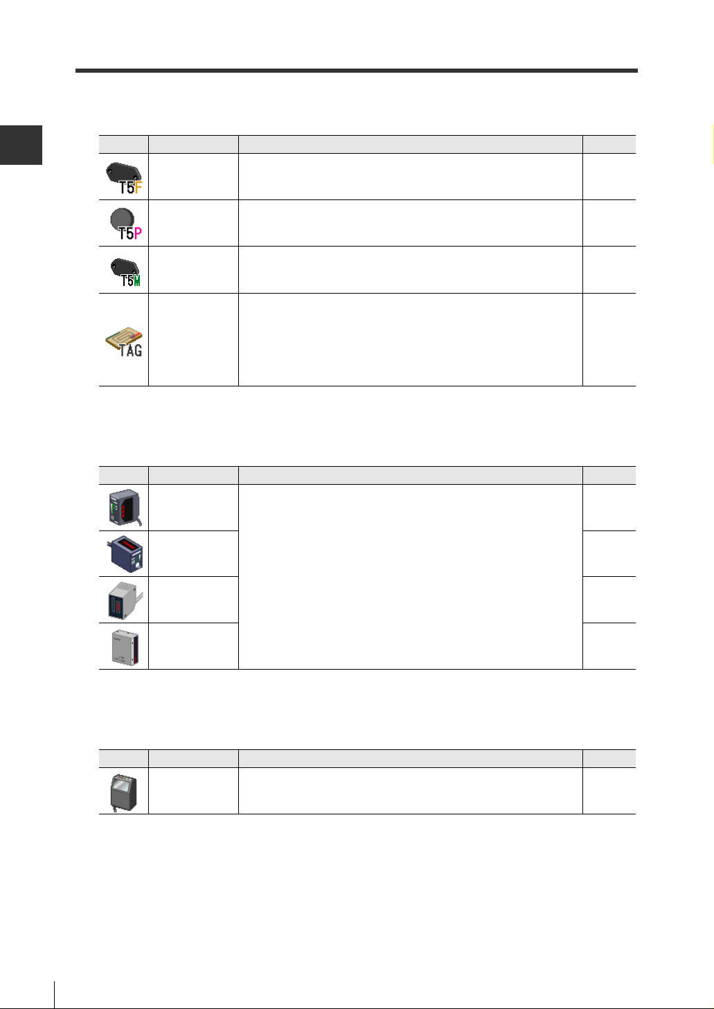
■ IC tags
2
Icon Device Description
OUTLINE OF AutoID Navigator
T5F** This IC tag is for FeRAM 2000 byte type RF-500 Series. 4-2
T5P10 This IC tag is for EEPROM 256 byte type RF-500 Series. 4-2
T5M** This IC tag is for EEPROM 992 byte type RF-500 Series. 4-2
Specify these tags when using the following standard IC tags that
General-purpose
tags
comply with ISO15693 other than Keyence IC tags:
• MB89R118
• I·CODE SLI
• Tag-it HF-I
• my-d
See Page
4-2
■ Barcode readers
Icon Device Description
BL-700
BL-600 4-11
BL-500 4-11
Standalone type compact barcode readers
See Page
4-11
BL-180 4-11
■ 2D code reader
Icon Device Description
SR-500 This is a small stationary 2D code reader. 4-18
2-8
See Page
Page 31

2-4 List of Functions
The following describes the functions of AutoID Navigator.
Basic Project File Functions
2
OUTLINE OF AutoID Navigator
Icon Name Functions
New project Creates a new project file. 3-10
Open project file Opens a saved project file. 3-10
Save project file Saves a created project file. 3-9
Option Settings
(communication
settings)
Update connection Establishes the connection with a selected device. 3-15
Sets the COM port (RS-232C port) on the
personal computer to communicate with.
The version of AutoID Navigator also be
confirmed.
Setup File Management Functions
Icon Name Functions
Open setup file Opens a saved setup file. 3-14
Save setup file
Write setting
Saves set parameters to a personal computer as a
setup file.
Writes (sends) the set parameters to a device.
See Page
2-3
See Page
3-14
3-16
Read setting
Edit parameter setup file Edits parameters on the currently selected device. 4-1
Edit macro setup file
Initialize setup
Te rminal function Sends commands to the target device. 6-2
Te st function
Reads (receives) set parameters from a device.
Edits macro setup files to be registered to the
currently selected head.
Clears set parameters and returns them to their
defaults.
Te sts the communications status between target
devices and IC tags, and the barcode reading
state.
3-17
5-1
3-14
6-3
2-9
Page 32

2
2-4 List of Functions
Device Add/Delete Functions
OUTLINE OF AutoID Navigator
Icon Name Functions
Rename
Add registered device Adds a device to a project. 3-8
Delete registered device
Applies the name of the project entered in the
[Name] field and the new name for a currently
registered device.
Delete a currently registered device from a
project.
See Page
3-8
3-8
2-10
Page 33

3
MANAGING PROJECTS
This chapter describes how projects are configured and setup files.
3-1 Outline of Projects . . . . . . . . . . . . . . . . . . . . . . . . . . 3-2
3-2 Creating Projects . . . . . . . . . . . . . . . . . . . . . . . . . . . 3-3
3-3 Registering Devices and Saving Projects . . . . . . . . 3-4
3-4 Editing Setup Files . . . . . . . . . . . . . . . . . . . . . . . . . .3-11
3-1
Page 34

3-1 Outline of Projects
A "project file" is a file that integrates and manages all of the devices required for production processes.
Devices to be connected to production processes can be managed efficiently by individual field
network or master units.
3
MANAGING PROJECTS
What Is a "Project"?
On AutoID Navigator, the parameters of devices to be connected and memory map- or macrorelated setups are managed as "projects."
Projects are managed in individual folder, and each folder is called a "project folder." On AutoID
Navigator, the following files are created in project folders.
File names can be entered by the user.
Project file (project name).ain
Parameter setup
file
Memory map
file
Macro setup file macro (number).aim
Log file
File File Typ e Description
Project management system component information (device
information, tag information) that indicates an individual production
process (line) is saved to this file. These files save currently
registered devices and network configurations.
Setup parameters and other information of each device are saved
config (number).aic
tagmap (number).ait
Te rminalLogFile.log
Te stLogFile.csv The communication log of the test mode is saved to this file.
to this file. Files are saved for individual devices. Files can be
renamed.
The memory map information (memo) of IC tags is saved to this
file. Files are saved for individual IC tags. Files can be renamed.
The macro operations of heads are saved to this file.
Files are saved for individual macros. Files can be renamed.
A log of communications performed by the terminal function is
saved to this file.
■ Project save destination
Any folder for saving project data can be created when saving projects.
Folders can freely managed, for example, by saving data in separate folders by individual project.
3-2
Page 35

3-2 Creating Projects
The following describes how to create projects.
Procedure for Creating a Project
The following shows the basic flow of operations for creating a project.
Registering devices and saving projects
Register the devices that configure the system to the project, and save these devices as a project.
1
"Registering Devices and Saving Projects" (page 3-4)
Setting parameters
Set the parameters of the devices registered to the project.
2
"How to Set Parameters" (page 3-13)
3
MANAGING PROJECTS
Sending set parameters
Send the parameters you have set up to the devices.
3
"Sending/Receiving Parameters" (page 3-15)
3-3
Page 36

3-3
When AutoID Navigator is started up, a new project is already created for use.
Determine the devices to register and how to register the devices suited to your particular requirements.
3
MANAGING PROJECTS
Signal Registration and Network Registration
There are two ways of registering devices on AutoID Navigator, "single registration" and "network
registration." With single registration, devices are not assigned an ID and are registered as independently operating devices. With network registration, devices are assigned an ID and are registered as devices that operate on a network.
Select the registration method to suit your particular requirements.
■ Single registration
When registering devices by single registration, register the
device with a project selected.
Registering Devices and Saving Projects
■ Network registration
When registering devices by network registration, first register the master unit, and then connected subordinate devices.
Note
IC tags are registered by single registration as they are not linked to the network.
When registering IC tags, select the IC tag to register from the list that is displayed when a project is selected and then register the device.
3-4
Page 37

3-3 Registering Devices and Saving Projects
● Example: Registering devices
With network registration, register controllers or heads as slave devices hierarchically to a master
device.
Multiple slave devices can be connected to a master.
Master device
N-410
Slave device
NX-50RS
SR-500
NX-50RS
Registering Devices by Single Registration
1
Click the device to register with a project selected, and click the "Regist" button, or doubleclick on the selected device.
3
MANAGING PROJECTS
To c o nt i nue registering devices by single registration, make sure that the project is still selected,
then register devices.
3-5
Page 38

3-3 Registering Devices and Saving Projects
Registering Devices by Network Registration
When registering devices by network registration, follow the procedure below to register devices
to the project.
3
MANAGING PROJECTS
1 Select the master unit, and click the "Regist" button.
This registers the master unit.
Note
•Parameters cannot be set to master units to be used on CC-Link or DeviceNet
from AutoID Navigator. Set parameters referring to the manual for the master
unit to be used.
•When building an RS-485 network system, select N-410 as the master unit.
2 Click the registered master unit, select the controllers to be added to the project as slaves,
and click the "Regist" button.
Note
3-6
Select the type of controller to match the network you are building. Select an NX50CL or NX-50DN as the controller
if the master unit is registered.
Page 39

3-3 Registering Devices and Saving Projects
3 The [ID registration] dialog box is displayed. Enter the ID and click the "OK" button.
Note
•AutoID Navigator automatically enters a serial number as the ID to prevent IDs
from being duplicated. When manually changing IDs, take care to prevent the
ID from duplicating another ID.
•When registering the NX-50CL, set the number of occupied stations and cyclic
setting. The NX-50CL occupies two to four stations depending on its settings.
Click to select the number of
stations from the list.
•The ID set here can also be changed later on.
"Renaming devices and changing IDs" (page 3-8)
3
MANAGING PROJECTS
4 Click the registered controller, select the head or barcode reader to be added to the project
as slaves, and click the "Regist" button.
When connecting multiple controllers (slave devices) to a master device, click the slave device to
add to the master device, select the controller and click the "Regist" button.
The following controllers can be connected to the master:
•N-410
NX-50RS
•Master unit
NX-50CL or NX-50DN
Note
•Only one type of controller can be registered to a single master unit. An NX50DN cannot be registered to a master unit to which an NX-50CL is registered.
•When the exclusive communication unit (N-48) is used, the head is connected
directly under the N-410.
3-7
Page 40

3-3 Registering Devices and Saving Projects
■ Renaming devices and changing IDs
When renaming a device or changing its ID, enter in the [Name] and [ID] fields at the bottom left of
the screen, and click the "Edit" button. A currently selected device can also be deleted or a new
device added.
3
MANAGING PROJECTS
Also, the position where devices are registered can be changed in the selection area just as if you
are moving files or folders by Explorer in Windows.
Renaming devices
The current device name is displayed in the
[Name] field. Enter the new name, and click
the "Edit" button.
Deletes the selected device.
Adds a slave device to the selected device.
Changing the ID No.
The current ID is displayed in the [ID] field.
Enter the new name, and click the "Edit" button.
1 Selecting the device to move
Devices currently connected to the
selected device also move.
2 When you drop the device at the
desired move destination, the [ID registration] dialog box is displayed.
Enter the ID to match the network you are
moving to, and click the "OK" button.
3-8
Page 41

3-3 Registering Devices and Saving Projects
Saving Projects
To s a ve a registered device configuration, follow the procedure below to save the configuration as
a project.
1 Select the project.
2 Enter the project name in the [Name] field, and click the "Edit" button.
The project name you entered is reflected.
3
MANAGING PROJECTS
3 Click (save project file) to save the project.
This saves the project as an ain file.
When the project file is saved, the setup files of the registered devices also are saved. Click the
"Save" button to save the files currently registered to the project.
If you click the "Cancel" button here, those setup files will not be saved, and the state will return to
the initial setup state when the project file was opened.
3-9
Page 42

3-3 Registering Devices and Saving Projects
Opening Projects
To o pen a saved project, click (open project file) on the tool bar, and select the project file
(**.ain) to be opened.
3
MANAGING PROJECTS
Creating a New Project
To c r eate a new project, click (new project) on the tool bar.
When a new project is created, the project that is currently being edited is discarded. When creating a new project, be sure to save the required project files and setup files.
3-10
Page 43

3-4 Editing Setup Files
AutoID Navigator manages the settings (parameters) by each individual device as a setup file.
This section describes how to save setup files, and how to read and write setup files from and to
devices.
Type of and Brief Description of Setup Files
Setup files are files to which the parameters of devices currently registered to a project are saved
and managed. Network IDs and communication parameters, and trigger inputs and other setup
information are saved to setup files by individual device. There are three types of setup files as
follows:
•Parameter setup files
•Memory map files
•Macro setup files
■ Parameter setup files
To s e t the parameters of a registered device, click .
The parameter settings of the currently selected device are displayed.
3
MANAGING PROJECTS
1 Click the device whose
parameters are to be set
2 Click to set the
parameters.
For details on setting parameters, see
(page 4-1).
"Chapter 4 SETTING DEVICE OPERATIONS"
3-11
Page 44

3-4 Editing Setup Files
y
■ Memory map files
To e d it t he memory map of a registered IC tag, click the desired IC tag to display the memory map
edit screen.
3
MANAGING PROJECTS
1 Click to select the IC tag whose
2 Click to select the area to edit.
3 Click the [MEMO] tab to edit the
memory map is to be displayed.
memory map.
You c a n execute a memory dump
clicking the [Memory dump] tab.
b
For details on memory map settings, see
(page 4-1).
"Chapter 4 SETTING DEVICE OPERATIONS"
■ Macro setup files
To s e t the macros of a registered RF-500 Series device, click .
The macro settings currently registered to the selected RF-500 Series device are displayed.
1 Click the RF-500 Series device to
set a macro to.
2 Click to set macro
operation.
To s e t m a cro operation, select the
macro to be set, and set the macro
operation on the [Act setting] tab.
To t e st operation of a macro, click the
[Macro test] tab.
For details on macro settings, see "Chapter 5 OTHER SETTINGS AND OPERATIONS" (page
5-1).
3-12
Page 45

3-4 Editing Setup Files
How to Set Parameters
When you have finished registered the component devices of a project, set the parameters of the
devices as follows.
There are three ways of setting parameters:
•By setting parameters by individual device
•By batch-setting parameters for a specific device model
•By setting parameters by individual files of a registered device
For details on the settings of each device, see
(page 4-1).
■ Setting parameters by individual device
When setting parameters by individual device, you can set parameters by individual device by
clicking the [Project] tab.
"Chapter 4 SETTING DEVICE OPERATIONS"
3
MANAGING PROJECTS
■ Batch-setting parameters for a specific device model
When the settings are common for a specific device model, you can batch-set parameters for the
specific model by clicking the [Unit] tab.
3-13
Page 46

3-4 Editing Setup Files
■ Setting parameters by individual files of a registered device
Parameters that have been set are saved as a file.
To change or edit settings by each individual saved file, select [File constitution] on the [Project]
tab. The parameter setup files of the project component devices are displayed in tree format by
file type.
3
MANAGING PROJECTS
■ Printing settings
The settings of each of the selected parameter setup files, memory map files and macro setup
files can be printed. Tag maps can also be saved in CSV file format.
Prints settings.
Saves tag maps in CSV file format.
Displays a print preview of the settings.
Saving Setup Files
To s a ve a setup file currently being edited, click (save) at the top right of the screen.
Opening Setup Files
To open an edited setup file, click (open) at the top right of the screen, and select the setup
file to be opened.
Initializing Setup Files
To i n itialize a setup file during editing, click (default setting) at the top right
of the screen.
3-14
Page 47

3-4 Editing Setup Files
Sending/Receiving Parameters
Parameters set in AutoID Navigator are not reflected as they are in a device. They must be sent
to the device.
Follow the procedure below establish a communication connection and send the parameters.
Note
To upd a t e a c o nnection with a device, the personal computer installed with
AutoID Navigator must be connected to the controller by an RS-232C cable.
■ Establishing the connection with the controller
1 Click (connect) on the tool bar.
The communication in progress dialog box is displayed and communication with the device starts.
3
MANAGING PROJECTS
When the connection is established, an icon is displayed to the left of the device name and the
parameter send/receive buttons are enabled.
When the following screens are displayed, this indicates that the connection between the device
and personal computer, or between devices failed.
Make sure that cable connections are correct.
The personal computer is not
connected to the device
The connection between the
controller and head failed
3-15
Page 48

3-4 Editing Setup Files
■ Sending parameters
To s e t p a ra meters preset on AutoID Navigator to a device, following the procedure below to send
the parameters.
3
MANAGING PROJECTS
1 Click (write setting) at the top right of the screen.
2 The confirmation dialog box is displayed. Click the "OK" button.
The communication in progress dialog box is displayed and parameters start to be sent.
3 The write completion dialog box is displayed. Click the "OK" button.
This completes transmission of the parameters.
Note
3-16
When the RF-500 Series is used, the parameter settings file and the macro settings file are created as separate files. The parameter settings and the macro settings need to be sent separately.
Page 49

3-4 Editing Setup Files
■ Receiving parameters
To read parameters that are already set to a device to AutoID Navigator, follow the procedure
below to receive the parameters.
Received parameters can be saved as setup files on AutoID Navigator, and their settings re-used
on other devices.
1 Click (read setting) at the top right of the screen.
2 The confirmation dialog box is displayed. Click the "OK" button.
The communication in progress dialog box is displayed and parameters start to be received.
3
MANAGING PROJECTS
3 The read completion dialog box is displayed. Click the "OK" button.
This completes reception of the parameters.
3-17
Page 50

3-4 Editing Setup Files
3
MANAGING PROJECTS
MEMO
3-18
Page 51

4
SETTING DEVICE
OPERATIONS
This chapter describes the parameter setups of the devices registered to
a project.
4-1 Setting IC Tags. . . . . . . . . . . . . . . . . . . . . . . . . . . . . 4-2
4-2 RF-500 Series Settings . . . . . . . . . . . . . . . . . . . . . . 4-5
4-3 BL Series Settings . . . . . . . . . . . . . . . . . . . . . . . . . .4-11
4-4 SR-500 Series Settings . . . . . . . . . . . . . . . . . . . . . 4-18
4-5 RS-485 Controller (NX-50RS) Settings . . . . . . . . . 4-25
4-6 CC-Link Controller (NX-50CL) Settings . . . . . . . . . 4-30
4-7 DeviceNet Controller (NX-50DN) Settings . . . . . . . 4-35
4-8 RS-485 Master Unit (N-410) Settings. . . . . . . . . . . 4-40
4-1
Page 52

4
SETTING DEVICE OPERATIONS
4-1 Setting IC Tags
Setting the Memory Map
AutoID Navigator allows you to partition IC tag memory area by individual application in advance
and append each area with a label (name) for management.
Each of the areas to which information is stored can be given a label (name) which can be made
use of when performing verification during design and when creating Specification Sheets.
The MEMO function allows you to color-code the display of changed addresses or write-protected
addresses so that you can intuitively grasp the memory map.
Edited memory map files can also be output as CSV format files.
Note
Memory maps that have been edited on AutoID Navigator cannot be written to IC
tags.
Use memory map information as materials for grasping the design and specifications of memory maps.
4-2
Page 53

Memo
The following describes the settings of the [MEMO] tab for IC tags.
(1) Section Memo (2) Details memo
4-1 Setting IC Tags
4
SETTING DEVICE OPERATIONS
(4) Specification of area
name
(5) Specification of area
color/protection
(6) Specification of area to be secured (7) "Add"/"Edit" button(3) Tag information
Item Description
(1) Section Memo
(2) Details memo
(3) Tag information
(4) Specification of area
name
(5) Specification of area
color/protection
(6) Specification of area to
be secured
(7) "Add"/"Edit" button
(8) "Delete" button Deletes the area currently being set (or changed).
Displays the details of IC tag memory divided up into section.
Details can be edit with a selection section appended with an area name.
Details can be edited when areas within a selected section are further divided
up into section.
Displays the type and memory size of the currently set IC tag.
* In the case of general-purpose IC tags, click the "Edit size" button to set the
size matched to the memory size of the IC tag you are using.
Enter the name of the area.
Select the display color of the area from the pulldown menu.
Color and protection can be specified only for Section Memo and cannot be
specified for Details memo.
* Protection cannot be specified to areas straddling blocks.
Protection can be specified to Section Memos at the boundary of blocks for an
IC tag currently being edited.
* IC tag memory is configured in 4-byte or 8-byte units called "blocks."
T5P10 and T5M** are configured in 4 bytes per block, and T5F** is configured
in 8 bytes per block. For details, refer to the "RF-500 Series Operation
Manual"
To secure area, specify the start of the address at [Start], and enter the end
address or the size of the area to be secured.
To specify the end address, click [End Address]. To specify by the size to be
secured, click [Size] and enter the size of the area to be secured.
The "Add" button is displayed when an area is newly set.
The "Edit" button is displayed when an already set area is selected.
(8) "Delete" button
4-3
Page 54

4
4-1 Setting IC Tags
Memory Dump
The details of IC tag memory can be read, and the start address and write details (ASCII text
strings) can be set and data written to IC tags.
SETTING DEVICE OPERATIONS
(1) Memory dump display
(9) Write Data
(4) Protect
indication
(3) Lock indication
(2) Head selection
(5) "Set write-protect" button
(8) Address
(7) "Write data" button
(6) "Read data" button
Item Description
(1) Memory dump display
(2) Head selection
(3) Lock indication
(4) Protection indication
"Set write-protect" button
(5)
(6) "Read data" button Performs communication with the IC tag to read memory details.
(7) "Write data" button Writes the details set at [Address] and [Write Data (ASCII)] to IC tag.
(8) Address Enter the start address to write data to.
(9) Write Data
Displays the memory dump result. Changes since the previous communication
are indicated in red.
Select the head to be used for communication with the IC tag currently being
edited from the pulldown menu.
When this checkbox is marked, write-locked areas are displayed color-coded in
the memory dump display.
When this checkbox is marked, write-protected areas are displayed colorcoded in the memory dump display.
Specifies the map range specified as write-protected (color-coded) as a
protected area.
Enter the data to be written. Enter data within 32 characters in ASCII code. To
enter in hexadecimal, mark the [Hex] checkbox.
■ Printing the Memory Map and Outputting a CSV File
The memory map created with AutoID Navigator can be printed or output as a CSV file. The
memory map output as a CSV file can also be managed using Excel or other applications as an
original form.
4-4
Page 55

4-2 RF-500 Series Settings
Parameters to be Set
There are four parameter items to be set up for the head. Switch to the desired setting item by
clicking the respective tab and set the parameters on that tab.
(1) Act setting
Setting Item Description See Page
(1) Act setting This tab is for setting the trigger mode and I/O terminals. 4-6
(2) RFID
communication
setting
(3) Output data setting This tab is for making the data output settings. 4-9
(4) RS-232 port setting
This tab is for making the settings for communication with an IC tag.
Write protection and UID authentication passwords are also set in this
item.
This tab is for setting devices connected to the head, and for setting
the communication speed, parity and other communication settings.
(2) RFID communi-
cation setting
(3) Output data
setting
(4) RS-232 port setting
4-7
4-10
4
SETTING DEVICE OPERATIONS
4-5
Page 56

4
4-2 RF-500 Series Settings
Act Setting
This section describes the [Act setting] tab for the head.
SETTING DEVICE OPERATIONS
■ Action mode
Item Description
Trigger setting
Access retry count
Auto trigger on delay
Select from Level trigger, One-shot trigger and Auto trigger as the trigger mode.
"RF-500 Series Operation Manual"
Set the access retry count when "One-shot trigger" or "Auto trigger" is set at
Trigger setting.
"RF-500 Series Operation Manual"
Set the time for preventing continuous action of the auto trigger when "Auto
trigger" is set at Trigger setting.
"RF-500 Series Operation Manual"
■ I/O setting
Item Description
Output duration
Input state Set Norm. open or Norm. close as the polarity of the input contact.
Set the ON time for when OUT1 to OUT4 terminals are used to transfer the
operation result to the host device.
4-6
Page 57

RFID Communication Setting
This section describes the [RFID communication setting] tab for the head.
4-2 RF-500 Series Settings
4
SETTING DEVICE OPERATIONS
■ Radio communication setting
Item Description
Select the IC tag to be registered to the head.
Tag 1/2/3
Active tag
Check read Set Disable/Enable for check read.
Write-protect Set Disable/Enable for Write-protect
"Optional tag" button
Set Tag 2 and Tag 3 by the "Optional tag" button.
"4-1 Setting IC Tags" (page 4-2)
Specify wh ich of Tag 1 to Tag 3 is to be used for the head.
Click this button to set types Tag 2 and Tag 3.
When registering a general tag, click General-tag and select the tag from
the pulldown menu.
■ Radio communication enable setting
Item Description
Communication enable
message
Count of communication
success
Set Send or Don’t send for Communication enable message.
Set the successful communication count within the range 1 to 255 times.
Set this when "Communication enable message" is set to send.
4-7
Page 58

4
SETTING DEVICE OPERATIONS
4-2 RF-500 Series Settings
■ Verification setting
Set the preset data when executing each of the "[VD] Verify data" and "[VB] Verify bit" commands.
Item Description
Preset data Set the preset data in ASCII code or Hexadecimal (HEX).
Preset bits Set the preset bit data.
Preset top address
Preset size (byte)
"
RF-500 Series Operation Manual"
Specify the top address and size when data read from an IC tag is to be taken
as the preset data.
■ Authentication setting
Set the password and authentication key for when the "[WK] Authentication key" command for
preventing forgery is executed.
These can be set when the "Authentication setting" key is clicked.
Item Description
Authentication key Set the authentication key.
New password Enter the new password.
Password Enter the current password.
RF-500 Series Operation Manual"
"
4-8
Page 59

Output Data Setting
This section describes the [Output data setting] tab for the head.
4-2 RF-500 Series Settings
4
SETTING DEVICE OPERATIONS
Item Description
Additional information
(processing time)
Additional information
(retry count)
Header
Delimiter
Checksum Select Don't add or Add for Checksum.
Send delay time Set the send delay time.
Set Disable/Enable for Additional information (processing time).
Set Disable/Enable for Additional information (retry count).
Select None, STX or ESC for Header.
Select CR, ETX or CR+LF for Delimiter.
4-9
Page 60

4
4-2 RF-500 Series Settings
RS-232C Port Setting
This section describes the [RS-232C port setting] tab for the head.
SETTING DEVICE OPERATIONS
Item Description
Baud rate Select the baud rate (bit/s) from the pulldown menu.
Parity Select None, Even or Odd for Parity.
Data bits Select 7 bits or 8 bits for Data bits.
Stop bit Select 1 bit or 2 bits for Stop bit.
Protocol
ID (1 to 31)
RTS/CTS protocol
Select None, PASS/RTRY, ACK/NAK or Multi-drop as the software-based
communication protocol.
Set the ID No. of the head.
This is set when "Multi-drop" is set at Protocol.
Select Disable or Enable for RTS/CTS protocol.
Set this when the Protocol setting is other than "Multi-drop".
4-10
Page 61

4-3 BL Series Settings
This section describes the settings of the KEYENCE Barcode Reader BL Series.
Parameters to be Set
There are four parameter items to be set up for the barcode reader. Switch to the desired setting
item by clicking the respective tab and set the parameters on that tab.
Note
Communication settings differ according to the barcode reader.
(1) Act setting (2) Barcode setting (3) Port setting (4) Other settings
4
SETTING DEVICE OPERATIONS
Setting Item Description See Page
(1) Act setting This tab is for making settings relating to reading of barcodes. 4-12
This tab is for making settings relating to the type of barcode to
(2) Barcode setting
(3) Port setting
(4) Other settings
be read, details of each individual barcode, and options and
special settings.
This tab is for making settings relating to communication
between the barcode reader and host or PLC.
This tab is for making settings relating to options (e.g. trigger
settings and reading of reversed barcodes).
4-14
4-15
4-17
4-11
Page 62

4
4-3 BL Series Settings
Act Setting
This section describes the [Act setting] tab for the barcode reader.
SETTING DEVICE OPERATIONS
Item Description
Select the read mode.
Read mode
Additional information
Decoding match count
Read error
Data-send timing This item must be set only when Read mode is set to "Single".
Repeat-reading interval
"Trigger setup" button The trigger input can be set up by clicking this button.
When "Single" is selected, set "Data-send timing".
When "Multi1" or "Multi2" is set, set "Repeat-reading interval".
Set the additional information.
"Scan count" can be set only when "Decoding count" is set.
"Symbology ID" and "PMI" can be set only on the BL-600.
When the "PMI" checkbox is marked, set each preventive maintenance
information (PMI) value within the range 0 to 100.
Enter any desired numerical value within the range 1 to 255 (times).
Normally, use the default (2 times).
Though a larger "Decoding match count" setting increases the reliability of
reading, the reading speed slows down. Alternatively, a smaller setting increases
the reading speed but lowers the reliability of reading.
On the BL Series, when the scan count (decoding counting) in which the barcode
was successfully decoded (read) becomes the value set at "Decoding match
count", the barcode is judged to have been read.
This item is for setting the error code that is sent to the personal computer by the
barcode reader when a barcode cannot be read.
Any error code up to eight characters in length can be set. However, normally,
use the default (ERROR). Leaving the text box blank disables sending of an error
code.
Set 1 to 255 (100 to 25500 ms) for Repeat-reading interval.
This item must be set only when Read mode is set to "Multi1" or "Multi2".
4-12
Page 63

■ Trigger setup
Item Description
Signal type
Input state
Input pulse width
Te st mode initiated with
trigger input ON
Te st mode initiated upon
power-up
Power-on trigger
Cmd for trigger ON
Cmd for trigger OFF
4-3 BL Series Settings
Select the "Signal type".
When "One-shot" is selected, One-shot input time is displayed. Set this time
within the range 1 to 255 (100 to 25500 ms).
Select Norm.open (to turn laser light emission ON with trigger input ON) or
Norm. close (to turn laser light emission ON with trigger input OFF).
This setting is to prevent a trigger input from being accepted unless it is ON
for the preset time or longer.
When "10 ms" is set, chattering of contacts can be ignored when an output
with a contact (e.g. relay) is connected for the trigger input.
Set this item only to initiate the test mode when trigger input turns ON or
when the power is turned ON. Normally, do not set this item.
* Trigger input does not function normally when "Test mode initiated with
trigger input ON".
Select this item to turn laser light emission ON at all times from the time that
power is turned ON. (On the BL Series, laser light emission is not turned ON
for five seconds after the power is turned ON )
Set the command characters for when reading operation is controlled (laser
light emission is turned ON/OFF) by sending a command.
Any command up to eight characters in length can be set. However, normally
use the defaults (LON for "Cmd for trigger ON" and LOFF for "Cmd for trigger
OFF").
4
SETTING DEVICE OPERATIONS
4-13
Page 64

4
4-3 BL Series Settings
Barcode Setting
This section describes the [Barcode setting] tab for the barcode reader.
On this tab, set the barcode type, the minimum and maximum code lengths, and other barcode
settings.
SETTING DEVICE OPERATIONS
Item Description
Code 1 to 4
Code length
"Detail" button
"Options" button
Select the type of barcodes from the pulldown menus.
* When completely different barcodes are set to "Code 1" to "Code 4", four
types of barcodes can be read without changing the respective settings.
Set the maximum and minimum number of digits for each barcode type at "Max"
and "Min", respectively.
When the "Edit" button is clicked, the [Code
length] dialog box is displayed. Enter the
desired numerical values, and click the
"OK" button.
* The code length that can be set differs
according to the type of barcode.
When the "Detail" button is clicked at "Code 1" to "Code 4", the [Barcode detail
setup] dialog box is displayed. Set each item in this dialog box.
* The details that can be set differ according to the type of barcode.
When the "Options" button is clicked at "Code 1" to "Code 4", the [Option setup]
dialog box is displayed. Set each item in this dialog box.
* The details that can be set differ according to the type of barcode.
4-14
Page 65

Port Setting (in case of BL-180 /500 /600 /700 )
This section describes the [Port setting] tab for the barcode reader.
4-3 BL Series Settings
4
SETTING DEVICE OPERATIONS
Item Description
Baud rate Select the baud rate (bit/s) from the pulldown menu.
Parity Select None, Even or Odd for Parity.
Data bits Select 7 bits or 8 bits for Data bits.
Stop bit Select 1 bit or 2 bits for Stop bit.
When PLCs are connected in a multi-drop link, select "Enable".
When "Enable" is selected, "ID (1 to 31)" is displayed. Enter the desired ID No.
Multi-drop link
RTS/CTS
PLC Link
"Character" button
within the range 1 to 31.
* Set the ID No. so that it is duplicated on each of the BL Series devices that are
connected in the multi-drop link.
* When "Enable" is set for Multi-drop link, "RTS/CTS" cannot be selected.
Select this item to set a delay in transmission of the read data according to
control by the RS-232C CTS signal.
Set Don't user or Use for PLC Link.
When PLC Link is set to Don't use
When PLC Link is set to Use
When this button is clicked, "Partition mark (1 char)" and "Inter delimiter (5
chars max)" can be set.
● Partition mark (1 char)
Set the character to be used as the partition marks between read barcode
data and additional information. Normally, use the default (:).
● Inter delimiter (5 chars max)
When Read mode is set to "Multi2" or "Multi3", this delimiter is used for
delimiting each of the read barcode data sections. Normally, use the default
(,).
→ Host setup (page 4-16)
→ PLC setup (page 4-16)
4-15
Page 66

4
SETTING DEVICE OPERATIONS
4-3 BL Series Settings
■ Host setup
The following describes setting of "Host setup" when PLC Link is set to "Disable".
Item Description
Handshaking
Checksum
Header
Delimiter
"Option" button
Select the communication format (protocol) when sending read barcode data to
the personal computer.
Data for checking for corrupted data in serial communications can be
appended.
Select the send format of read barcode data.
When "Custom" is selected, set the header using up to five characters in each
of the text boxes (ASCII or HEX).
When this button is clicked, the [Send delay time] can be set.
Set the time to wait for sending the response that is returned by the BL Series
to commands sent to the BL Series from the personal computer within the
range 0 to 255 ms.
■ PLC setup
The following describes setting of "PLC setup" when PLC Link is set to "Use".
Item Description
PLC type Select the type of PLC to be connected.
PLC trigger area
DM head address Set the DM head address within the range 0000 to 9900.
Station No.
File register
Select this item to apply a trigger for reading barcodes on the BL Series in a
PLC Link.
Set the station No. within the range 0 to 31.
* This item is not displayed when "KEYENCE KV Series" is selected at PLC
type.
To use a file register as a device, select "Enable". When a file register is used
set the block No. of the file register within the range 0 to 255.
,
4-16
Page 67

Other Settings
This section describes the [Other settings] tab for the barcode reader.
4-3 BL Series Settings
4
SETTING DEVICE OPERATIONS
Item Description
OK/NG output duration Set 1 to 255 (10 to 2550 ms) for OK/NG output duration.
STABILITY LED
Preset data
"Special setting" button When this button is clicked, the special settings are displayed.
When "Use stability LED" is selected, the reading stability is indicated by the
STABILITY LED when the BL Series is reading barcodes normally.
Set the barcode data to register within 32 characters.
* Preset data can be set up to 64 characters when the barcode type is
CODE128 and the start code is CODE-C.
■ Special setting
The items that are displayed under Special setting differ according to the BL Series model.
Item Description
Read reverse barcode
Quiet zone scale
Decode cancel count Do not change this item.
Tes t S W output
When "Enable" is selected, reversed barcodes (black swapped with white, and
vice versa) can be read.
Set the minimum value for expansion of the quiet zone that can be read by the
BL Series. Enter the number of times the quiet zone can expand by with respect
to the narrow bar width (smallest bar width of a bar code) of the barcode.
* Change this item only when the quiet zone of the barcode in use is narrow.
Normally, do not change this item.
When "Enable" is selected, data such as the barcode read by the BL Series and
the read rate is sent to the personal computer.
To disable transmission of data, do not select "Enable".
* This item is applied to all reading operations that use the TEST switch.
4-17
Page 68

4
SETTING DEVICE OPERATIONS
4-4 SR-500 Series Settings
This section describes the settings of the KEYENCE Barcode Reader BL Series.
Parameters to be Set
There are six parameter items to be set up for the SR-500 Series. Switch to the desired setting
item by clicking the respective tab and set the parameters on that tab.
Note
Communication settings differ according to the barcode reader.
(1) Act setting
(2) Code setting
Setting Item Description See Page
(1) Act setting Set read mode, additional information, PMI preset value, etc.
(2) Code setting
(3) Camera setting
(4) Timing setting Set the signal type, input state, etc.
(5) Port setting Set the detailed settings for the serial communication.
(6) Other settings
Set the type of code to be read, the detailed settings for each
code, etc.
Set the detailed settings for each parameter bank, the alternate
function, etc.
Set the verification/preset setting, switch operation of the unit,
etc.
(3) Camera setting
(4) Timing setting
(5) Port setting
(6) Other settings
4-19
4-20
4-21
4-22
4-23
4-24
4-18
Page 69

4-4 SR-500 Series Settings
Act Setting
This section describes the settings for the read mode and data transmission.
4
SETTING DEVICE OPERATIONS
Item Description
Read mode
Data-send timing Set the timing at which to send data.
Multi Repeat-reading interval Set the repeat-reading interval. (100 to 25 500 ms, 100 ms increment)
Multi Pointer-lighting interval Set the lighting time of the laser pointer. (0 to 990 ms, 10 ms increment)
Additional information Select the information to be added to the read data.
PMI preset value Enter a value for adding the predictive maintenance information.
Read error
Select the single mode or the multi mode. If the multi mode is selected, set
the repeat-reading interval and the pointer light time.
Set an error code to issue when a code cannot be read. Specify within eight
characters. No error code is sent if left blank.
4-19
Page 70

4
4-4 SR-500 Series Settings
Code Setting
This section describes the settings for the codes to be read with the SR-500 Series.
SETTING DEVICE OPERATIONS
Item Description
Code 1 to Code 8 Select a code to read.
Code length Set the maximum and minimum number of digits for the code to read.
Detail Set detailed conditions for each code.
Options Set the conditions for the maximum code length output.
4-20
Page 71

4-4 SR-500 Series Settings
Camera Setting
This section describes the settings for camera parameters for each parameter bank.
4
SETTING DEVICE OPERATIONS
Item Description
Select this checkbox to enable the alternate function. To fix a parameter
Alternate
Write protect
Code setting
Shutter speed Set the shutter speed. (0 to 9900 ms, 100 ms increment)
Read Setting Select Inverse or Mirror.
Retry timeout Set the retry time. (10 to 2550 ms, 10 ms increment)
Parameter timeout
Teaching Setting Set the teaching conditions for the quick calibration.
bank, select this checkbox only for the bank to be used while deselecting it
for other banks.
Prohibits overwriting the parameter bank with quick teaching.
(Normally enabled.)
Select the code to use for the parameter bank to be set.
Only the code selected in the Code setting tab can be set.
Set the parameter bank switch time when using the alternate function.
(10 to 2550 ms, 10 ms increment)
4-21
Page 72

4
4-4 SR-500 Series Settings
Timing Setting
This section describes the settings for the read timing conditions.
SETTING DEVICE OPERATIONS
Item Description
Signal type
Input state Select Normally open or Normally closed.
Input pulse width Select 2 ms or 10 ms.
Trg delay time Set the trigger delay time (0 to 9990 ms, 10 ms increment)
Te st mode initiated
Cmd for trigger ON
Cmd for trigger OFF
Power-on trigger Turns on the trigger when the power turns on.
Select Level or One-shot. When selecting One-shot, set One-shot input time
as well.
Set this when initiating the test mode when a trigger is input or the power
turns ON.
Change the trigger input ON command within eight characters.
The default is LON.
Change the trigger input OFF command within eight characters.
The default is LOFF.
4-22
Page 73

Port Setting
This section describes the settings for the RS-232C output of the SR-500.
4-4 SR-500 Series Settings
4
SETTING DEVICE OPERATIONS
Item Description
Baud rate, Data bits, Parity,
Stop bit
Multi-drop link
RTS/ CTS Select Disable or Enable.
Protocol Select None, PASS/RTRY, or ACK/NAK.
Format length
Checksum Select Don’t add or Add.
Header/Delimiter Set the same item as the one set in the connected external device.
Character Set Partition mark, Inter delimiter, and Composite delimiter.
Set the same values as those of the connected external device.
When connecting the N-410, select Enable and enter ID. When connecting
the NX-50RS, no setting is needed.
Select Don’t add or Add. When Add is selected, the number of characters of
the sending data is read and added in front of the data.
4-23
Page 74

4
4-4 SR-500 Series Settings
Other Settings
This section describes other operation conditions.
SETTING DEVICE OPERATIONS
Item Description
Verif ication setting/Preset
data
Tune switch
Te st switch
Pointer setting Set the lighting condition of the laser pointer.
Where NG image is saved Set the save destination of NG images.
Segment LED Set whether or not to display the camera parameter number.
I/O setting
External light Disables the LEDs on the unit when using an external light.
Register the verification start position, number of digits, and preset data.
Set the operations of the Tune switch and the Test switch.
Set the output terminal ON time (10 to 2550 ms, 10 ms increment)
Output Busy term: Sets the operation of the BUSY terminal.
Output upon power-up: Issues the BUSY output when the power
turns on.
Output NG term at reading error: Set this when the BL-U1/U2 is used.
The read error signal can be output from
the NG terminal.
4-24
Page 75

4-5
RS-485 Controller (NX-50RS) Settings
Parameters to be Set
There are six parameter items to be set up for the SR-500 Series. Switch to the desired setting
item by clicking the respective tab and set the parameters on that tab.
(1) RS-232C (modular) setting (2) Head setting (3) Terminal setting (4) RS-485 setting
4
SETTING DEVICE OPERATIONS
Setting Item Description See Page
(1) RS-232C (modular)
setting
(2) Head setting This tab is for setting communication with the head. 4-27
(3) Terminal setting This tab is for setting the I/O terminals. 4-28
(4) RS-485 setting
This tab is for setting communication with the host. 4-26
This tab is for setting communication over an RS-485 connection.
The ID is set here.
4-29
4-25
Page 76

4
4-5 RS-485 Controller (NX-50RS) Settings
RS-232C (modular) Setting
The following describes the settings of the [RS-232C (modular) setting] tab for the NX-50RS.
SETTING DEVICE OPERATIONS
Item Description
Baud rate Select the baud rate (bit/s) from the pulldown menu.
Parity Select None, Even or Odd for Parity.
Data bits Select 7 bits or 8 bits for Data bits.
Stop bit Select 1 bit or 2 bits for Stop bit.
IN1 output to host Select Disable/Enable for IN1 output to host.
IN2 output to host Select Disable/Enable for IN2 output to host.
Send data Select Disable/Enable for Send data.
IN data format Set the format for output to host.
4-26
Page 77

4-5 RS-485 Controller (NX-50RS) Settings
Head Setting
The following describes the settings of the [Head setting] tab for the NX-50RS.
4
SETTING DEVICE OPERATIONS
Item Description
Autoconnection with head Select Disable/Enable for Autoconnection with head.
Baud rate Select the baud rate (bit/s) from the pulldown menu.
Parity Select None, Even or Odd for Parity.
Data bits Select 7 bits or 8 bits for Data bits.
Stop bit Select 1 bit or 2 bits for Stop bit.
4-27
Page 78

4
4-5 RS-485 Controller (NX-50RS) Settings
Termin al Setting
The following describes the settings of the [Terminal setting] tab for the NX-50RS.
SETTING DEVICE OPERATIONS
Item Description
Input select Select For head or For general-use for the IN1 and IN2 terminal functions.
Input state
Input pulse width Select 2ms or 10ms for the input time constant of the IN1 and IN2 terminals.
Output select
Output state
Select Norm. open or Norm. close for the input state of the IN1 and IN2
terminals.
Select From head, Host or Bus master for the functions of the OUT1 to OUT4
terminals.
Select Norm. open or Norm. close for the output state of the OUT1 to OUT4
terminals.
4-28
Page 79

4-5 RS-485 Controller (NX-50RS) Settings
RS-485 Setting
The following describes the settings of the [RS-485 setting] tab for the NX-50RS.
4
SETTING DEVICE OPERATIONS
Item Description
Slave ID
Baud rate Select the baud rate (bit/s) from the pulldown menu.
Parity Select None, Even or Odd for Parity.
Data bits Select 7 bits or 8 bits for Data bits.
Stop bit Select 1 bit or 2 bits for Stop bit.
"NX-50 Series Operation Manual"
Tip
The RS-485 settings of NX-50RS can be unified by the "Apply to all the slaves" button
on the [RS-485 setting] tab for the N-410.
"4-8 RS-485 Master Unit (N-410) Settings" "RS-485 Setting" (page 4-46)
Select 0 to 31 as the slave ID of the NX-50RS. When "0" is set, the NX-50RS is
set in a standalone configuration (i.e. not a multi-drop configuration).
4-29
Page 80

4
SETTING DEVICE OPERATIONS
4-6
CC-Link Controller (NX-50CL) Settings
Parameters to be Set
There are four parameter items to be set up for the CC-Link controller (NX-50CL). Switch to the
desired setting item by clicking the respective tab and set the parameters on that tab.
(1) RS-232C (modular) setting (2) Head setting (3) Terminal setting (4) CC-Link setting
Setting Item Description
(1) RS-232C (modular)
setting
(2) Head setting This tab is for setting communication with the head. 4-32
(3) Terminal setting This tab is for setting the I/O terminals. 4-33
(4) CC-Link setting
This tab is for setting communication over an RS-232 connection. 4-31
This tab is for setting communication over a CC-Link connection.
The slave ID (station No.) is set here.
See Page
4-34
4-30
Page 81

4-6 CC-Link Controller (NX-50CL) Settings
RS-232C (modular) Setting
The following describes the settings of the [RS-232C (modular) setting] tab for the NX-50CL.
4
SETTING DEVICE OPERATIONS
Item Description
Baud rate Select the baud rate (bit/s) from the pulldown menu.
Parity Select None, Even or Odd for Parity.
Data bits Select 7 bits or 8 bits for Data bits.
Stop bit Select 1 bit or 2 bits for Stop bit.
IN1 output to host Select Disable/Enable for IN1 output to host.
IN2 output to host Select Disable/Enable for IN2 output to host.
Send data Select Disable/Enable for Send data.
IN data format Set the format for output to host.
4-31
Page 82

4
4-6 CC-Link Controller (NX-50CL) Settings
Head Setting
The following describes the settings of the [Head setting] tab for the NX-50CL.
SETTING DEVICE OPERATIONS
Item Description
Autoconnection with head Select Disable/Enable for Autoconnection with head.
Baud rate Select the baud rate (bit/s) from the pulldown menu.
Parity Select None, Even or Odd for Parity.
Data bits Select 7 bits or 8 bits for Data bits.
Stop bit Select 1 bit or 2 bits for Stop bit.
4-32
Page 83

4-6 CC-Link Controller (NX-50CL) Settings
Termin al Setting
The following describes the settings of the [Terminal setting] tab for the NX-50CL.
4
SETTING DEVICE OPERATIONS
Item Description
Input select Select For head or For general-use for the IN1 and IN2 terminal functions.
Input state
Input pulse width Select 2ms or 10ms for the input time constant of the IN1 and IN2 terminals.
Output select
Output state
Select Norm. open or Norm. close for the input state of the IN1 and IN2
terminals.
Select From head, Host or Bus master for the functions of the OUT1 to OUT4
terminals.
Select Norm. open or Norm. close for the output state of the OUT1 to OUT4
terminals.
4-33
Page 84

4
4-6 CC-Link Controller (NX-50CL) Settings
CC-Link Setting
The following describes the settings of the [CC-Link setting] tab for the NX-50CL.
SETTING DEVICE OPERATIONS
Item Description
Slave ID (No.) Select 1 to 63 as the slave ID of the NX-50CL.
Baud rate Select the baud rate (bit/s) from the pulldown menu.
Station count Select 2, 3 or 4 for Station count.
Expansion cycle setting
→ NX-50CL
Master
NX-50CL
"Save CSP file" button
→ Master
Write size
Output-data size
Read size
Input-data size
Select 1 times, 2 times, 4 times, or 8 times for Expansion cycle
setting.
The value calculated from the [Station count] and [Expansion cycle
setting] setting values is displayed.
Saves the settings as a CSP file.
"NX-50 Series Operation Manual"
4-34
Page 85

4-7
DeviceNet Controller (NX-50DN) Settings
Parameters to be Set
There are four parameter items to be set up for the DeviceNet controller (NX-50DN). Switch to the
desired setting item by clicking the respective tab and set the parameters on that tab.
(1) RS-232C (modular) setting (2) Head setting (3) Terminal setting (4) DeviceNet setting
4
SETTING DEVICE OPERATIONS
Setting Item Description See Page
(1) RS-232C (modular)
setting
(2) Head setting This tab is for setting communication with the head. 4-37
(3) Terminal setting This tab is for setting the I/O terminals. 4-38
(4) DeviceNet setting
This tab is for setting communication over an RS-232C
connection.
This tab is for setting communication over a DeviceNet
connection.
The slave ID (MAC ID) is set here.
4-36
4-39
4-35
Page 86

4
4-7 DeviceNet Controller (NX-50DN) Settings
RS-232C (modular) Setting
The following describes the settings of the [RS-232C (modular) setting] tab for the NX-50DN.
SETTING DEVICE OPERATIONS
Item Description
Baud rate Select the baud rate (bit/s) from the pulldown menu.
Parity Select None, Even or Odd for Parity.
Data bits Select 7 bits or 8 bits for Data bits.
Stop bit Select 1 bit or 2 bits for Stop bit.
IN1 output to host Select Disable/Enable for IN1 output to host.
IN2 output to host Select Disable/Enable for IN2 output to host.
Send data Select Disable/Enable for Send data.
IN data format Set the format for output to host.
4-36
Page 87

4-7 DeviceNet Controller (NX-50DN) Settings
Head Setting
The following describes the settings of the [Head setting] tab for the NX-50DN.
4
SETTING DEVICE OPERATIONS
Item Description
Autoconnection with head
Baud rate Select the baud rate (bit/s) from the pulldown menu.
Parity Select None, Even or Odd for Parity.
Data bits Select 7 bits or 8 bits for Data bits.
Stop bit Select 1 bit or 2 bits for Stop bit.
Select Disable/Enable for Autoconnection with head.The following settings are
disabled when Autoconnection with head is set to Enabled.
4-37
Page 88

4
4-7 DeviceNet Controller (NX-50DN) Settings
Termin al Setting
The following describes the settings of the [Terminal setting] tab for the NX-50DN.
SETTING DEVICE OPERATIONS
Item Description
Input select Select For head or For general-use for the IN1 and IN2 terminal functions.
Input state
Input pulse width Select 2ms or 10ms for the input time constant of the IN1 and IN2 terminals.
Output select
Output state
Select Norm. open or Norm. close for the input state of the IN1 and IN2
terminals.
Select From head, Host or Bus master for the functions of the OUT1 to OUT4
terminals.
Select Norm. open or Norm. close for the output state of the OUT1 to OUT4
terminals.
4-38
Page 89

4-7 DeviceNet Controller (NX-50DN) Settings
DeviceNet Setting
The following describes the settings of the [DeviceNet setting] tab for the NX-50DN.
4
SETTING DEVICE OPERATIONS
Item Description
Slave ID (ID) Select 0 to 63 as the slave ID of the NX-50DN.
Baud rate Select the baud rate (bit/s) from the pulldown menu.
Write size Select the write size from the pulldown menu.
→ NX-50DN
Master
NX-50DN
"Save EDS file" button
→ Master
Output-data size
Read size Select the read size from the pulldown menu.
Input-data size
Displays the number of bytes of the output data.
* This numerical value becomes the size of the DeviceNet link data.
Displays the number of bytes of the input data.
* This numerical value becomes the size of the DeviceNet link data.
Saves the settings as a EDS file.
4-39
Page 90

4
4-8 RS-485 Master Unit (N-410) Settings
Parameters to be Set
There are five parameter items to be set up for the RS-485 master unit (N-410). Switch to the
desired setting item by clicking the respective tab and set the parameters on that tab.
(1) Main setting (3) Protocol setting (4) RS-232 setting (5) RS-485 setting(2) Slave setting
SETTING DEVICE OPERATIONS
Setting Item Description
(1) Main setting This tab is for setting the operation mode and trigger. 4-41
(2) Slave setting This tab is for setting the slave station to be connected. 4-42
(3) Protocol setting This setting is for setting the protocol and PLC. 4-43
(4) RS-232 setting This tab is for setting communication over an RS-232 connection. 4-45
(5) RS-485 setting This tab is for setting communication over an RS-485 connection. 4-46
Registered devices are displayed when N-410 is selected at the selection area. To set parameters, click the "Param" button to switch to the parameter setting display.
See Page
4-40
Page 91

4-8 RS-485 Master Unit (N-410) Settings
Main Setting
The following describes the settings of the [Main setting] tab for the N-410.
4
SETTING DEVICE OPERATIONS
Item Description
Host mode
Trigger setup
Read mode Select Single or Multi for Read mode.
Data-send timing
Signal type
State Select Norm. open or Norm. close as the polarity of the input contact.
Input pulse width Select 2ms or 10ms for the input time constant of the input contact.
Command for trigger ON
Command for trigger OFF
Select Multi-drop link mode, BL (SR) Multi-head mode or RF Multi-head mode
for Host mode.
Set the trigger for when Multi-head mode is used.
When Interference suppression is enabled, set the timing ON time to 50 to 2550
ms.
Select After read or At trigger-OFF for Data-send timing.
* This item is enabled only in the Single label mode.
Select from Level and One-shot as the signal type.
* When One-shot is set, set the One-shot input time to 100 to 25500 ms.
Set the Command for trigger ON using an ASCII text string or Hexadecimal.
The command is automatically converted to ASCII text string or Hexadecimal
before it is displayed.
Set the Command for trigger OFF using an ASCII text string or Hexadecimal.
The command is automatically converted to ASCII text string or Hexadecimal
before it is displayed.
4-41
Page 92

4
4-8 RS-485 Master Unit (N-410) Settings
Slave Setting
The following describes the settings of the [Slave setting] tab for the N-410.
The slave station can be set within the range 1 to 31 stations.
SETTING DEVICE OPERATIONS
Item Description
ID setup
Slave station enable/
disable setting
Select from None, N48+BL (SR), N48+RF, 50RS+BL (SR), and 50RS+RF.
•N48+BL (SR) . Combination of N-48 or BL-U1 and BL/SR Series
•N48+RF . . . . . Combination of N-48 or BL-U1 and RF Series
• 50RS+BL (SR) Combination of NX-50RS and BL/SR Series
• 50RS+RF . . . Combination of NX-50RS and RF Series
* Select "None" when no slave station exists for the corresponding ID No.
Select Disable/Enable for a registered slave station.
To enable a registered slave station, mark the checkbox.
4-42
Page 93

4-8 RS-485 Master Unit (N-410) Settings
Protocol Setting
The following describes the settings of the [Protocol setting] tab for the N-410.
On the [Protocol setting] tab, set the general-purpose protocol or PLC Link.
When "PLC setting" is set to "Disable", set the general-purpose protocol. When "PLC setting" is
set to "Enable", set PLC Link.
4
SETTING DEVICE OPERATIONS
■ General-purpose protocol
The following describes setting of the general-purpose protocol when "PLC setting" is set to "Disable".
Item Description
Handshaking Select None, PASS/RTRY or ACK/NAK for Handshaking.
Add ID Select Enable or Disable for Add ID.
Checksum
Read-error code
Header
Delimiter
Select Enable or Disable for Checksum (to check for data corruption during
communication).
This item is for sending an error code from the N-410 to the personal computer
when communication fails.
Any error code up to eight characters in length can be set. However, normally,
use the default (ERROR).
Select None, STX, ESC or Custom for the text string to be used as the header.
When "Custom" is selected, specify the desired text string in ASCII code of
Hexadecimal (HEX).
Select CR, CR+LF, ETX or Custom for the text string to be used as the
delimiter.
code of Hexadecimal (HEX).
When "Custom" is selected, specify the desired text string in ASCII
4-43
Page 94

4
SETTING DEVICE OPERATIONS
4-8 RS-485 Master Unit (N-410) Settings
■ PLC Link
The following describes setting of the PLC Link when "PLC setting" is set to "Enable".
Item Description
DM head address Set the head address of data memory (DM) to be used in the PLC Link.
Station No. Set the station No. within the range 00 to 31.
Input trigger area Set Disable or Enable for Input trigger area.
PLC type
When PLC Link is set to "Enable", select MELSEC Series, KEYENCE KV Series
or SYSMAC Series.
4-44
Page 95

4-8 RS-485 Master Unit (N-410) Settings
RS-232C Setting
The following describes the settings of the [RS-232C setting] tab for the N-410.
4
SETTING DEVICE OPERATIONS
Item Description
Baud rate Select the baud rate (bit/s) from the pulldown menu.
Parity Select None, Even or Odd for Parity.
Data bits Select 7 bits or 8 bits for Data bits.
Stop bit Select 1 bit or 2 bits for Stop bit.
RTS/CTS protocol Select Disable or Enable for RTS/CTS protocol.
4-45
Page 96

4
4-8 RS-485 Master Unit (N-410) Settings
RS-485 Setting
The following describes the settings of the [RS-485 setting] tab for the N-410.
SETTING DEVICE OPERATIONS
Item Description
Baud rate Select the baud rate (bit/s) from the pulldown menu.
Parity Select None, Even or Odd for Parity.
Data bits Select 7 bits or 8 bits for Data bits.
Stop bit Select 1 bit or 2 bits for Stop bit.
"Apply to all the slaves"
button
Slave direct command timeout
Applies the parameters currently set on the N-410 to all of the NX-50RS's
that are currently connected to the N-410 that is being set up.
Select 15 seconds or 60 seconds as the command timeout for slave devices.
4-46
Page 97

5
OTHER SETTINGS AND
OPERATIONS
This section describes the macro settings for the RF-500 Series, quick
calibration for the SR-500 Series, and the procedure to create a quick
setup code.
5-1 Settings Macros . . . . . . . . . . . . . . . . . . . . . . . . . . . . 5-2
5-2 Setting Macro Operations. . . . . . . . . . . . . . . . . . . . . 5-3
5-3 Quick Calibration Operation . . . . . . . . . . . . . . . . . . . 5-6
5-4 Creating a Quick Setup Code. . . . . . . . . . . . . . . . . . 5-9
5-1
Page 98

5
5-1 Settings Macros
This section describes how to register macros to the RF-500 Series and switch macros.
Macros and Active Macros
Up to three macros can be registered to an RF-500 Series.
Switch the Macro 1 to Macro 3 tabs to select the respective operations.
On the RF-500 Series, one of registered macros 1 to 3 can be set as the active macro. The active
macro is the macro that is executed by a trigger.
OTHER SETTINGS AND OPERATIONS
(1) Selection of macro
(2) Selection of active macro
5-2
Item Description
(1) Selection of macro
(2) Selection of active macro
(3) [Act setting] tab
(4) [Macro test] tab
(3) [Act setting] tab
Switch macro operation by Macro 1, Macro 2 and Macro 3 to display the
macro.
Select the trigger input and macro to be executed by the [M*] command from
the pulldown menu.
Sets 16 operation commands.
"Act Setting" (page 5-4)
Performs an operation test on the currently displayed macro.
"Macro Test" (page 5-5)
(4) [Macro test] tab
Page 99

5-2 Setting Macro Operations
This section describes macro operation settings.
Setting Macro Operations
(1) Operation patterns (4) Continuous operation settings
(3) Input data
(2) Result data (5) Output destination settings
5
OTHER SETTINGS AND OPERATIONS
Item Description
(1) Operation patterns
(2) Result data The destination for storing the result data of a read operation is displayed.
(3) Input data The type of the source data in the operation is displayed.
(4) Continuous operation
settings
(5) Output destination
settings
The operation settings of the currently set command are displayed.
Set operation on the [Act setting] tab.
Set whether or not to execute the current macro operation continuously.
To continue the operation, select the "Cont" checkbox.
Select from OK/NG/ERR as the result of macro operation, and set so that the
result is output to one of OUT1/OUT2/OUT3. Also, set serial output of the
operation result to (enabled) or (disabled).
5-3
Page 100

5
5-2 Setting Macro Operations
Act Setting
The following describes the [Act setting] tab for the macro registered to the head.
In this operation, set the commands to be used in the macro and their parameters.
For details on parameters, refer to the "Operation Manual."
(1) Command selection
OTHER SETTINGS AND OPERATIONS
(2) Macro editing (3) "Apply" button (4) "Cancel" button
Item Description
(1) Command selection
(2) Macro editing Edit the content of a selected command.
Address Set the head address of the data to be set as the command parameter.
Size Set the size of the data to be set as the command parameter.
Data
Operator
Process
Place
Ta g type
Map
(3) "Apply" button Reflects the operation settings in the selected operation pattern.
(4) "Cancel" button Discards the settings.
Select from 16 operation commands.
For details on commands, refer to the "RF-500 Series Operation Manual"
Select the type of input data from the pulldown menu. Enter ASCII/HEX
(hexadecimal)/BIT (binary)/BLOCK as the data according to the type of operation.
Select the operator.
* This is displayed when setting the "Compare data" or "Write after operation"
command.
Set the operation when there is a write-protected or write-locked area in the
specified range.
* This is displayed when setting the "Fill data" command.
Set the place to write the checksum.
* This is displayed when setting the "Write checksum" or "Confirm checksum"
commands.
Select the type of IC tag from the pulldown menu.
* This is displayed when setting the "Set write-protect", "Confirm write-
protect", "Set write-lock" or "Confirm write-lock" commands.
The tag map is displayed in a separate window. You can select from tag maps
whose [Address] and [Size] specifications above are displayed.
Register the macro you have set to the head.
Note
•The macro currently registered to the head is overwritten.
•The macro settings file and the parameter settings file are created as separate
files. The parameter settings and the macro settings need to be sent separately.
5-4
Click (write setting).
 Loading...