

Page 1
Digital Pressure Sensor
WARNING
SET AP-C40 MODE
MPa
12
Pressure display units
*Apply the units sticker here.
Pressure display
Mode button
Manual adjustment button
Set button
Wiring
connector
Sensor head
connector
Mounting screws
(M3 x 2)
Operational indicator /
Output 1, Output 2
1 2
About
25 mm
About
25 mm
Connector
body
Connector
cover
Connector
lock
Orange
Brown
Blue
Gray
Pressure
connection
Insert until you hear a
clicking sound.
with 2-Color Display
AP-C40W(P) Series
Instruction Manual
1. Safety Precautions
96M0983
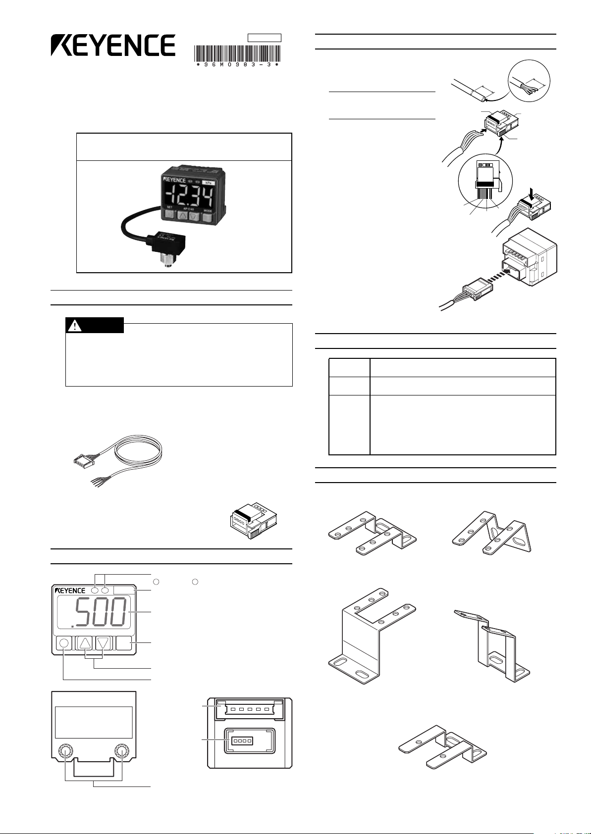
3. Sensor Head Installation
1) Cut the cable to an appropriate
length and strip away about 25
mm of the outermost insulation.
Note: It is not necessary to
remove insulation from the
core wires.
2) Insert the cables after aligning
them with the colors on the seal
on top of the connector body.
3) Press together the body and the
connector cover into which the
cables were inserted to make a
connection (use a pair of pliers
or similar tool to press them together).
4) Insert the sensor head connector into the hole of the amp unit.
To remove the connector, depress the connector lock and
pull it out.
* Do not reuse sensor head
connectors that have already
been pressure-connected.
●
Do not use this product in safety circuits such as those designed to
protect human workers.
●
This product does not employ an explosion-proof construction. Do not
use it in the presence of flammable gasses, liquids, or powders.
●
This is a direct current power supply type sensor. Application of an
alternating current may result in explosion or fire.
■ Accessories
●
1 connector cable (2 m)
●
1 instruction manual
2. Part Names
●
1 unit scale label
●
1 sensor head connector
4. About Sensor Head Installation
Common Do not subject the case to pressure sufficient to deform
AP-41(M) • Use a torque of 0.3 N
43 • 44 for the sensor head conduits.
AP-48 Use a torque of 5 N
its shape during installation.
•
m or lower to tighten the screws
•
the sensor head conduits.
Take care that no foreign objects enter the sensor when
opening one of the pressure ports to atmospheric air.
Take care not to bend the pressure ports.
Connect the “High” port to the high-pressure side of the
system and the “Low” port to the low-pressure side.
m or lower to tighten the screws for
5. Mounting Brackets (option)
Dedicated mounting hardware is available for the sensor, allowing it to be
installed in a range of locations.
Horizontal mounting bracket Wall mounting bracket
(AP-BO1) (AP-BO2)
Faceplate/ceiling mounting bracket Tilted mounting bracket
(AP-BO3) (AP-BO4)
Substitution bracket (AP-B05)
*Distance between arms is same as the AP-30/40 Series brackets.
1
Page 2
<Output 1>
P1
0
Output 1
OFF ON OFF
P2
0
OFF ON OFF
<Output 2>
Output 2
<Output 1>
P1
H1
Output 1
OFF ON OFF
0
P2
OFF ON OFF
H2
0
<Output 2>
Output 2
Hi
Lo
Output1/Output2
OFF ON ONOFF OFF
<Output 1/Output 2>
0
<Output 1>
P1
Output 1
OFF ON OFF
0
<Output 2>
0
Output 2
OFF ON OFF
P2
0
0
Shift
Zero shift input
T1
<Zero shift>
<Output 1>
P1
Output1
Zero shift input
OFF ON
OFF ON
0
<Output 2>
Hi
Lo
Output 2
OFFONOFF OFF
ON
Analog
output (1 to 5 V)
0 V
Main
circuit
Blue
Pink
12 to 24 VDC
Main circuit
Pink
Brown
(Short-circuit current 5 mA or less)
AP-AO1 Panel mounting bracket
SET AP-C40 MODE
MPa
Panel mounting ring
Front protective
cover
Panel-mounted bodyPanel-mounted bodyPanel-mounted body
Side where the metallic
contacts are visible faces up.
Connector cable
12 to 24 VDC
5 to 40 VDC
5 to 40 VDC
0V
Main circuit
Overcurrent
protection circuit
Load
Load
Input/output
circuit
Analog output/
zero shift input: switchable
Control output 1
Control output 2
Brown
Blue
Black
White
Pink
12 to 24 VDC
0V
Load
Load
Main circuit
Overcurrent
protection circuit
Black
White
Pink
Analog output/
zero shift input: switchable
Control
output 1
Control
output 2
Brown
Blue
Input/output
circuit
(Short-circuit current 5 mA or less)
Main
circuit
Blue
Pink
CAUTION
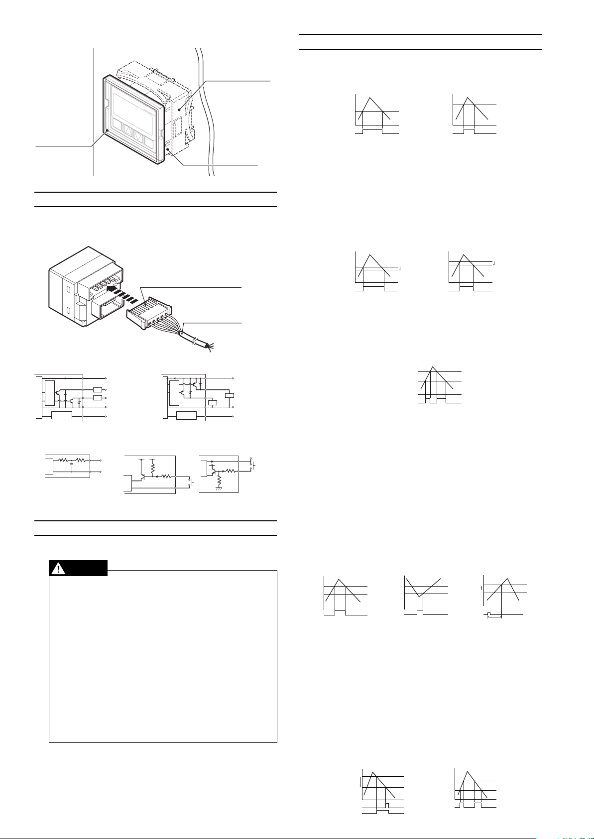
8. Detection Mode Operation
■ General-purpose mode (F-1)
This mode allows the user to configure 2 detection points.
Control output 1: Turns ON when pressure exceeds setting P1.
Control output 2: Turns ON when pressure exceeds setting P2.
SET AP-C33 MODE
MPa
6. Connection Method and Diagrams
Insert the included connector-tipped cable into the sensor's connector.
Position the connector so that the side of the connector where the metallic
contacts are visible is facing up.
Input/output circuit (AP-C40W) Input/output circuit (AP-C40WP)
*Hysteresis when operating in general-purpose mode and application
modes 1 and 2 is 0.5% of F.S. in the standard and high-speed modes.
During focus mode operation, it is 0.1% of F.S.
■ Variable hysteresis mode (F-2)
Two detection points may be user-configured, and hysteresis for both
may also be set.
Control output 1
: Turns ON when pressure exceeds setting P1. Turns OFF
when pressure drops the selected hysteresis amount
below P1.
Control output 2:
Turns ON when pressure exceeds setting P2. Turns OFF
when pressure drops the selected hysteresis amount
below P2.
■ Window mode (F-3)
The user may select a pair of upper (Hi) and lower (Lo) thresholds, and
the sensor turns OFF when the pressure falls outside of the resulting
range.
*Control output 1 is 0.5% of F.S. during standard and high-speed
operation, it has a hysteresis of 0.1% of F.S. in the focus mode, and
control output 2 has a hysteresis of 0.
Analog output circuit
7. Precautions for Safe Use
Follow these guidelines. Failure to do so may result in product damage.
■
■
■
Zero shift input circuit Zero shift input circuit
(AP-C40W) (AP-C40WP)
Connections
●
Always ground the frame ground terminal when using an off-the-shelf
switching regulator.
●
Use separate conduits for power line and high voltage lines , since use
of a common conduit may result in device malfunction caused by noise .
●
Improper wiring may result in the device becoming excessively hot or
in device damage.
Notice about CE marking
●
Attach the ferrite core (OP-87505) if you extend a sensor head cable/
amplifier power cable to 3 m or more to use.
(Attachment position: within 100 mm from the amplifier unit of a
power cable, Number of turns: 2)
Other
●
Do not use this sensor with corrosive gasses or liquids.
●
Do not insert objects such as wire into the pressure insertion area.
Doing so may result in the device failing to operate properly due to
damage to the pressure-sensitive elements.
●
Do not use sharp-tipped objects to press the setting keys.
■ Application mode 1 (A-1)
This detection mode is optimum for use in suction detection applications.
Recommended heads: AP-41/41M/44
Control output 1:
Control output 2:
Zero shift: Shifts the zero point immediately after setting the zero
P1: Pressure setting for control output 1.
T1: Zero shift timer setting (ms) < Variable between 0 and 1,999 ms
P2: Pressure setting for control output 2.
*P2 is unrelated to zero shift and is always based on the current ambi-
ent pressure.
■ Application mode 2 (A-2)
This mode is optimum for use in leak test applications.
Recommended head: AP-43
Control output 1
Control output 2:
P1: Pressure setting for control output 1.
Hi: Upper threshold setting for control output 2.
Lo: Lower threshold setting for control output 2.
*The Hi and Lo values are unrelated to zero shift and are always based
on the current ambient pressure.
2
Suction pressure detection.
Turns ON when pressure exceeds setting P1.
Detection of vacuum burst pressure (or confirmation of
vacuum arrival pressure).
Turns ON when the pressure falls below setting P2. May
be set during focus mode operation, although there are
restrictions on the setting range.
shift timer once zero shift input is received.
: Leak pressure detection.
Turns ON when pressure falls below setting P1.
*Output only when receiving zero shift input.
Window comparator output for detection of fill pressure.
Turns OFF when pressure falls outside the range determined by upper (Hi) and lower (Lo) thresholds. Fill pressure values are displayed with the center pressure as 0
during focus mode operation.
Page 3

Detection mode
Operating mode
Standard
Focus mode
High-speed
Zero shift input
Analog output
N.O./N.C.
2.5 msec
5 msec
100 msec
500 msec
General-purpose mode
Variable hysteresis mode
Window mode
Application mode 1
Application mode 2
Analog/zero shift
Standard
Eco mode
Power-save
Chatter prevention
Sets response time.
* F-1 and F-2 mode only
Values that fall between the P1 and P2
settings will be displayed in green,
while values outside that range will be
displayed in red.
When
A-1/A-2 is
selected
during
fixed mode
operation
When
operating
mode is
• Two-point tuning
• Active tuning
* High-speed mode provides a 1-ms
high-speed response.
*1 Displayed in kPa during focus mode operation.
*2 Displayed in gf/cm
2
during folus mode operation.
*3 Displayed in bar during standard mode operation.
Displayed in mbar during focus mode operation.
Current value
Reference value
Hold value
Units
Increase the
setting.
Decrease the
setting.
For other
than
Focus center pressure
After 4 sec
of no key
operation.
Reference value*
Press for 3 sec or more.
+
+
■ Toggling the
display
■ Manual configuration
Settings are
manually
configured. The
display changes
for each mode.
* Toggling the
display of
settings (see the
diagram below).
*
Manual configuration
only during F-3/A-2
mode operation.
Current value
Peak hold
Bottom hold
* The reference value is
the pressure value when
zero shift input is
received and is replaced
only when zero shift
input is selected.
■ Mode
configuration
* See the Focus Mode section
of Part 10 for the center
pressures that can be
selected.
N.O.
N.O.
N.C.
N.C.
N.O.
N.C.
N.C.
N.O.
Control
output 1
Control
output 2
• N.O. = normal open.
• N.C. = normal close.
Display color (7-segment)
ON: Red, OFF: Green
ON: Green, OFF: Red
Normally red
Normally green
Within set value: Green
Outside set value: Red
()
kPa (41, 43, 44, 48),MPa (43)*
1
kgf/cm2 (43)kgf/cm2 *2 (48)
mmHg (41, 44)
inHg (41, 44)
psi (41, 43, 44, 48)
mbar (41, 44, 48)*3, bar (43)
9. Sensor Configuration
Flashes
for 3 sec.
Setting
Target object
present
Target object
absent
■ Toggling the display of settings
●
General-purpose mode/F1
●
Variable hysteresis mode/F-2
●
Window mode/F-3
●
Application mode 1/A-1
●
Application mode 2/A-2
■ Two-point tuning (F-1/F-2)
The sensor is made to detect the pressures when the target object is
present and then absent for confirmation of target suction pick-up, and
the intermediate value is used.
Control output 1 configuration: When P1 (H1) is selected on the settings
display.
Control output 2 configuration: When P2 (H2) is selected on the settings
display.
■ Active tuning (A-1)
See Section 11.
Note:• Press and hold the MODE button ( ) for at least 3 seconds to return to the current
value/reference value/hold value display from each of the mode setting screens.
• Press the left side on the manual adjustment button ( ) while holding down the
mode button ( ) to return to the previous display.
• The current value will be displayed based on the ambient pressure conditions prevalent
at that time without regard to zero shift input when the P2 setting display is selected for
A-1 mode or when the HI and Lo setting displays are selected for A-2 mode.
• The sensor must be configured manually when operating in the F-3/A-2 modes. The
SET button ( ) will not function.
3
Page 4

10
Head
41
43
44
48
43
48
41
44
41
44
41
43
44
48
41
43
44
48
-20,0/-30,0/-40,0/-50,0/-60,0/-70,0/-80,0
200/300/400/500/600/700/800
80,0/60,0/40,0/20,0/0,0/-20,0/-40,0/-60,0/-80,0
-80,0/-60,0/-40,0/-20,0/0,0/20,0/40,0/60,0/80,0
2,00/3,00/4,00/5,00/6,00/7,00/8,00
-800/-600/-400/-200/0/200/400/600/800
-100/-200/-300/-400/-500/-600/-700
600/500/400/200/0/-200/-400/-500/-600
0,0/-5,0/-10,0/-15,0/-20,0/-25,0/-30,0
20,0/15,0/10,0/5,0/0,0/-5,0/-10,0/-15,0/-20,0
-1,00/-3,00/-5,00/-7,00/-9,00/-11,00/-13,00
10,0/30,0/50,0/70,0/90,0/110,0/130,0
12,00/9,00/6,00/3,00/0,00/-3,00/-6,00/-9,00/-12,00
-12,00/-9,00/-6,00/-3,00/0,00/3,00/6,00/9,00/12,00
-200/-300/-400/-500/-600/-700/-800
2,00/3,00/4,00/5,00/6,00/7,00/8,00
800/600/400/200/0/-200/-400/-600/-800
-800/-600/-400/-200/0/200/400/600/800
Selected units
bar
psi
inH
mmH
GF
Pa
kPa
mbar
mbar
kgf/cm
2
gf/cm
2
mmHg
psi
inHg
bar
Unit Center Pressure
0
-0.1MPa
O.K.
Zero shift input
Zero shift input
-0.5MPa
N.G.
1MPa
Head 1 V to 5 V
AP-41/41M 0to-101.3 kPa
AP-43 0to+1 MPa
AP-44/48 -101.3 to +101.3 kPa
Active 2 point tuning
Active 1 point tuning
Suction
Vacuum burst
P1 P2 T1
Automatic
configuration
_
_
Automatic
configuration
Manual
configuration
_
ApplicationType
P2
P1
Time
Zero shift input
T1
Vacuum
Step 1)
Step 2)
Device operation
with no target
object present
Operation
for several
cycles
Operation
for several
cycles
Device operation
with target
object present
Sensitivity
difference
display
Sampling
Sampling
Start
Start
Finish
Finish
Target object
present
Setting
display
Sampling
Start Finish
.Explanation of Features
■ Focus mode
Focus mode increases all display resolutions by a factor of 10.
Normal mode Focus mode
The following focus center pressures can be selected for the models
noted in the table below. (Unit: kPa)
* The current value is displayed as ±20% of the F.S. range with the
focus center pressure as the reference value (0).
■ Zero shift
Zero shift input forces the pressure at that time to be defined as zero.
This feature is useful in applications that require the detection of a certain amount of pressure fluctuation without being influenced by changes
in the original pressure.
●
During A-1 mode operation (active hold display)
The hold values are reset each time the pressure value exceeds (or falls
below) the setting, and the peak hold (bottom hold) will then vary from
this point.
Peak hold value:
The peak hold value will be reset once a value is
encountered that exceeds setting P1, and new peak
values will be held from that point.
Bottom hold value:
The bottom hold value will be reset once a value is
encountered that falls below setting P2, and new
bottom values will be held from that point.
■ Power-save
The value display will be turned off during power-save operation to reduce the amount of power consumed.
●
Use of any keys during eco mode operation will revert the sensor to
its normal display. The sensor will return to the eco display when
there is no key input for a period of 3 minutes.
■ Switching the display color
Corresponds to either output 1 or output 2 based on which setting display has been selected.
* rGr can only be set when either the F-1 or F-2 mode is selected.
Values that fall between the P1 and P2 settings will be displayed in
green, while values outside that range will be displayed in red.
11
.Active Tuning
(Example: leak testing)
Zero shift input received when a container is filled with air will allow the
amount of leak after a certain time to be displayed as negative pressure.
This approach eliminates the influence of small variations in the final fill
pressure of the container.
The pressure value (reference value) when zero shift input is received
can be verified from the current value display by pressing the button
to switch to the reference value display.
( ⇔ )
Press the button once more to return to the current value display.
■ Analog output
A voltage corresponding to the pressure value is output.
* Ambient pressure compensation is also applied to analog output.
* The resolution of analog voltage output will not be enhanced during
focus mode operation.
■ Peak/bottom hold display
The maximum (minimum) values are displayed continuously after power to
the sensor is turned on.
The active hold display indicated below is used when the A-1 mode is selected.
How to display hold values/
From current value/reference value display
The minimum value during zero shift input is displayed for the bottom
hold during A-2 mode operation.
Resetting the peak/bottom hold values/
Pressing for 3 seconds or more while the peak and bottom hold
values are being displayed will reset the values.
*The values will also be reset when power to the sensor is turned off,
+ / Activates peak hold display.
+ /Activates bottom hold display.
and when the device's detection mode or operating mode is changed.
■ Perform these steps first
Select the setting display as indicated below before performing the
tuning procedures.
Active 2 point tuning: Select either P1 or T1 for the setting display.
Active 1 point tuning: Select P2 from the settings display.
■ Active 2 point tuning / a tuning method suited for automatically configuring suction pick-up detection pressures
The zero shift timer setting is manually configured, and the sensor automatically selects the best pressure setting (P1) for this value.
■ Active 1 point tuning / tuning optimized for vacuum burst
detection
The sensor automatically selects the best pressure setting (P2) for
vacuum burst detection.
12
.Ambient Pressure Compensation
Open the applied pressure to the surrounding air so that it equals the
ambient pressure and press the button for 3 seconds or more while
the current value or reference value is being displayed.
The ambient pressure point will be corrected.
4
Page 5

*1 Ambient pressure can be corrected within a range of ±5 % of F.S.
Model
Environmental
resistance
Units
Pressure resistance
Adaptive fluids
Pressure type
Temperature
characteristics
Pressure port
Housing material
Weight
Ambient temperature
Relative humidity
Vibration
Shock Resistance
Rated pressure range
7 g (not including cables) / 70 g (including
3-m cable) (4.8 g / 67.8 g for AP-41M)
35 g/98 g
10 to 55 Hz, compound amplitude 1.5 mm, 4 hours for each of XYZ axes
35 to 85 % RH (No condensation)
0 to +50 °C (No freezing)
M5 male screw PT1/8
Within ±2 % of F.S. (at 25°C)
(in temperature range of 0 to 50°C)
Differential
pressure
Gage pressure
Air, non-corrosive gasses
AP-48
500 kPa500 kPa 1.5 MPa 500 kPa
AP-41/41M
AP-43 AP-44
1,000 m/s
2
, 10 times for each of XYZ axes, total 60 time
Case: PBT; Screws: SUS303
kPa
bar
psi
inHg
mmHg
kgf/cm
2
0 to -101.3
101.3 to -101.3
-101.3 to 101.3
0 to 1.000 MPa
0 to -29.9
0 to -14.69
0 to -1.013
0 to 145.0
0 to 10.00
29.9 to -29.9
14.69 to -14.69
1.013 to -1.013
-1.013 to1.013
-14.69 to 14.69
0 to -760
0 to 10.20
760 to -760
-1.033 to 1.33
Model
Head combination
Display method
Configuration/display
range *1
Operating status indicators
Repeatability
Hysteresis *2
Display temperature
characteristics
Response
(chatter
prevention feature)
Zero shift input
Control output
Analog output
Housing material
Weight
Accessories
Power supply voltage
Current
consumption
Vibration
Relative humidity
Ambient temperature
Rating
Resolution
Environmental
resistance
AP-C40W(P)
12 to 24 VDC±10% Ripple (P-P) 10% or less
Red 4.5 digit, 7 segment LED display (4.5 mm character height)
AI indicator (green) Display refresh rate: 10 times/sec
-15 to +110 % of F.S.
±0.2% of F.S. or less
Variable (standard 0.5% of F.S.)
Within ±1% of F.S. (at +25°C)
(within 0 to +50°C temperature range)
Selectable from 1, 2.5, 5, 100, 500 ms
Input time 2 ms or greater
(Switchable with analog output.)
NPN open collector Max. 100 mA (40 V or less)
Residual voltage 1 V or less, 2 outputs (NO/NC switchable)
PNP open collector Max. 100 mA (30 V or less) *3
Residual voltage 1 V or less, 2 outputs (NO/NC switchable)
1 to 5 V Output impedance 1 kΩ or less
(Switchable with zero shift input.)
0 to +50 °C (No freezing)
35 to 85 % RH (No condensation)
10 to 55 Hz, compound amplitude 1.5 mm, 2 hours for each of XYZ axes
Main unit cover : Polycarbonate
Approx. 80 g (including 2-m cable) / Approx. 35 g (not including cable)
Head connectors, units sticker connector cable
Red LED x 2 (supports control output 1 / control output 2)
12 V operation( NPN/PNP)
780mW (65mA)/960mW (80mA) or less
24 V operation( (NPN/PNP)
1080mW (45mA)/1440mW (60mA) or less
540mW (45mA)/660mW (55mA) or less 840mW (35mA)/1080mW (45mA) or less
AP-41/41M
Normal
Eco mode
AP-43 AP-44 AP-48
Standard mode
High-resolution mode
kPa
kgf/cm
2
mmHg
inHg
psi
bar
kPa
kgf/cm
2
mmHg
inHg
psi
bar
0.1
0.01
0.1
0.1
0.01
0,001
0.001
0.02
1
0.1
0.01
0.001
0.01
0.01
0.1
0.002
0.1 mbar 0.2 mbar
0.001 MPa 0.1
1
0.1
0.02
0.001
0.02
0.2
0.01
0.2 mbar
0.1
0.001
0.02
0.001
0.02
0.2 gf/cm
2
0.0040.004
• No difference in sensitivity
(during 2 point tuning/active
tuning).
• There is an applied pressure
of ±5 % of F.S. during ambient
pressure compensation.
• There is no sensor head
connected.
• The connection to the sensor head
is broken.
• An excess current is flowing to the
control output.
• Reading is falling below
(exceeding) configuration/display
pressure range.
• Reading is exceeding (falling
below) configuration/display
pressure range.
• When there were not at least 2
shift inputs during active 2 point
tuning.
Adjust the air pressure device so that
there will be a difference in sensitivity.
(Return to atmospheric pressure.)
Repeat atmospheric compensation.
Verify that a sensor head is connected
and turn the power on again.
Repair the sensor head disconnection
and turn the power to the sensor back
on.
Check the load and return it to the
rated range.
Return the pressure to the rated
pressure range.
Return the pressure to the rated
pressure range.
Repeat the active tuning procedure
so that there are at least 2 shift inputs.
Display Cause Solution
Units
Detection mode
Operating mode
N.O./N.C. switching
Analog/zero shift
*
Chatter prevention
Display color
Power-save
j
When atmospheric pressure compensation has been performed, the
settings will be saved even when power to the sensor is turned off.
*2 Can also be used when operating in focus mode, although for some
center pressures the display will read FFF.
(Atmospheric pressure compensation is being performed.)
13
.Key Lock
Disables operations that would modify the sensor’s configuration. Display
content can be toggled.
Pressing and holding either or for at least 3 seconds while pressing
button will lock the keypad and cause the display to flash.
* The same key combination will deactivate the key lock feature.
14
.Specifications
■ Sensor head
15.
Error Displays and Corrective Actions
■ Error displays during normal operation
* Contact KEYENCE for information about error displays other than those
described above.
16
.Default Mode Settings (Initialization)
The sensor ships with the following configuration.
■ Amplifier
*1 During focus mode operation, restricted to focus range.
*2 During focus mode operation, standard 0.1% of F.S.
*3 The AP-C40WP uses PNP output.
*Press button 5 times while holding down the button to return the
sensor to its default configuration.
WARRANTIES AND DISCLAIMERS
KEYENCE, at its sole option, will refund, repair or replace at no charge any
defective Products within 1 year from the date of shipment. Unless stated
otherwise herein, the Products should not be used internally in humans, for
human transportation, as safety devices or fail-safe systems. EXCEPT FOR
THE FOREGOING, ALL EXPRESS, IMPLIED AND STATUTORY
WARRANTIES, INCLUDING WARRANTIES OF MERCHANTABILITY,
FITNESS FOR A PARTICULAR PURPOSE AND NONINFRINGEMENT OF
PROPRIETARY RIGHTS, ARE EXPRESSLY DISCLAIMED. KEYENCE
SHALL NOT BE LIABLE FOR ANY DIRECT, INDIRECT, INCIDENTAL,
CONSEQUENTIAL OR OTHER DAMAGES, EVEN IF DAMAGES RESULT
FROM THE USE OF THE PRODUCTS IN ACCORDANCE WITH ANY
SUGGESTIONS OR INFORMATION PROVIDED BY KEYENCE. In some
urisdictions, some of the foregoing warranty disclaimers or damage limitations
may not apply.
Copyright (c) 2008 KEYENCE CORPORATION. All rights reserved.
0983E 1022-3 96M0983 Printed in Japan
5
E 1101-3
 Loading...