

Page 1
Ultra-compact Digital
Hold in place
with wrench
(12mm).
CAUTION
Pressure Sensor
AP-C30K (P) Series
Instruction Manual
1. Safety Precautions
WARNING
●
Do not use this product in safety circuits such as those designed to
protect human workers.
●
This product does not employ an explosion-proof construction. Do not
use it in the presence of flammable gasses, liquids, or powders.
●
This is a direct current power supply type sensor. Application of an
alternating current may result in explosion or fire.
???
96M1038
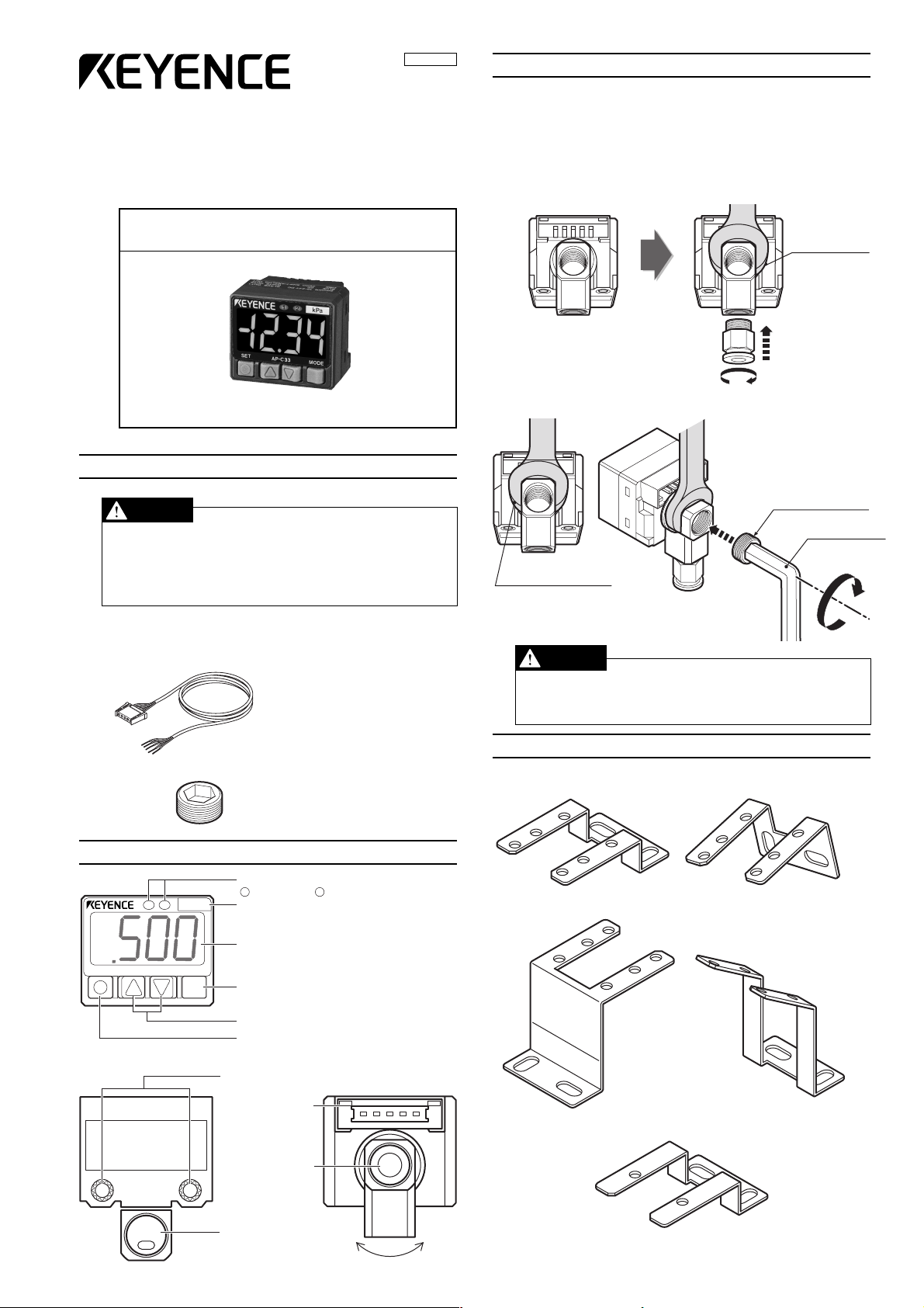
3. Pipe Connections
You can select from one of two pressure ports: one on the back of the
sensor that can accommodate a pipe leading directly away from the back
of the sensor, and one on the side of the sensor to accommodate a pipe
leading away from the sensor at a right angle.
1) The pressure port is 1/8 of NPT. Commercially available air pressure
joints and nipples can be used with the port.
When attaching the joint, use a wrench to hold the pressure port in
place as illustrated below.
2) Attach the included valve plug to the pressure port not being used.
Valve plug with
hexagonal hole
Hexagonal
wrench (5mm)
Hold in place with
wrench (12 mm).
■ Accessories
●
1 connector cable (2 m)
●
1 valve plug with hexagonal hole
2. Part Names
21
SET AP-C33K MODE
MPa
Operational indicator
1 2
Output 1 Output 2
Pressure display unit
*Apply the units sticker here.
Pressure display
Mode button
Manual adjustment button
Set button
Mounting screws
(M3 x 2)
Wiring
connector
Pressure
port (rear)
●
1 unit scale label
●
1 instruction
manual
• Do not use a torque in excess of 10 Nm when tightening the joint.
Doing so may damage the joint.
• Apply sealing tape when attaching the joint in order to prevent air leaks.
4. Mounting Brackets (option)
Dedicated mounting hardware is available for the sensor, allowing it to be
installed in a range of locations.
Horizontal mounting bracket Wall mounting bracket
(AP-BO1) (AP-BO2)
Faceplate/ceiling mounting bracket Tilted mounting bracket
(AP-BO3) (AP-BO4)
Pressure port
(side)
Approx. ± 90°
Substitution bracket (AP-BO5)
1
* Distance between arms is same as the AP-30/40 Series brackets.
Page 2
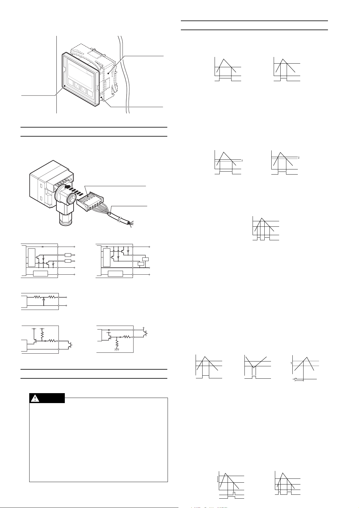
AP-AO1 Panel mounting bracket
SET
AP-C40
MODE
MPa
<Output 1>
P1
H1
Output 1
OFF ON OFF
0
Hi
Lo
Output1/Output2
OFF ON ONOFF OFF
<Output 1/Output 2>
0
<Output 1>
P1
Output1
Zero shift input
OFF ON
OFF ON
0
Panel mounting ring
SET
Front protective
MPa
AP-C33
MODE
cover
Panel-mounted sample
Panel-mounted sample
5. Connection Method and Diagrams
Insert the included connector-tipped cable into the sensor’s connector.
Position the connector so that the side of the connector where the metallic
contacts are visible is facing up.
Side where the metallic
contacts are visible faces up.
Connector cable
7. Detection Mode Operation
■ General-purpose mode (F-1)
This mode allows the user to configure 2 detection points.
Control output 1: Turns ON when pressure exceeds setting P1.
Control output 2: Turns ON when pressure exceeds setting P2.
<Output 1>
P1
0
OFF ON OFF
Output 1
*Hysteresis is a standard 0.5% of F.S. when operating in general-pur-
pose mode and application modes 1 and 2. During focus mode operation, it is 0.2% of F.S.
■ Variable hysteresis mode (F-2)
Two detection points may be user-configured, and hysteresis for both
may also be set.
Control output 1
: Turns ON when pressure exceeds setting P1. Turns OFF
when pressure drops the selected hysteresis amount
below P1.
Control output 2:
Turns ON when pressure exceeds setting P2. Turns OFF
when pressure drops the selected hysteresis amount
below P2.
■ Window mode (F-3)
The user may select a pair of upper (Hi) and lower (Lo) thresholds, and
the sensor turns OFF when the pressure falls outside of the resulting
range.
*Control output 1 is a standard 0.5% of F.S. During focus mode opera-
tion, it has a hysteresis of 0.2% of F.S., and control output 2 has a
hysteresis of 0.
Output 2
P2
Output 2
<Output 2>
P2
0
<Output 2>
0
OFF ON OFF
OFF ON OFF
H2
Input/output circuit Input/output circuit
(AP-C30K/C31K/C33K) (AP-C30KP/C31KP/C33KP)
Brown
Black
Load
White
Load
Blue
Analog output/
zero shift input: switchable
Pink
12 to 24 VDC
5 to 40 VDC
5 to 40 VDC
0V
protection circuit
Main circuit
Overcurrent
Input/output
circuit
protection circuit
Main circuit
Overcurrent
Input/output
circuit
Analog output circuit
Pink
Blue
Analog
output (1 to 5 V)
0 V
circuit
Main
Zero shift input circuit Zero shift input circuit
(AP-C30K/C31K/C33K) (AP-C30KP/C31KP/C33KP)
circuit
Main
circuit
Main
(Short-circuit current 5 mA max.)
Pink
Blue
(Short-circuit current 5 mA max.)
6. Precautions for Safe Use
Follow these guidelines. Failure to do so may result in product damage.
CAUTION
■
Connections
Input/output circuit
●
Always ground the frame ground terminal when using an off-the-shelf
switching regulator.
●
Use separate conduits for power line and high voltage lines, since use
of a common conduit may result in device malfunction.
●
Improper wiring may result in the device becoming excessively hot or
in device damage.
■
Other
●
Do not use this sensor with corrosive gasses or liquids.
●
Do not insert objects such as wire into the pressure insertion area.
Doing so may result in the device failing to operate properly due to
damage to the pressure-sensitive elements.
●
Do not use sharp-tipped objects to press the setting keys.
Brown
Black
White
Load
Load
Blue
Analog output/
zero shift input: switchable
Pink
12 to 24 VDC
Brown
Pink
12 to 24 VDC
0V
■ Application mode 1 (A-1)
This detection mode is optimum for use in suction detection applications.
Recommended sensor heads: AP-C30K/C30KP/C31K/C31KP
Control output 1:
Control output 2:
Zero shift: The zero point is shifted immediately after the zero
P1: Pressure setting for control output 1.
T1: Zero shift timer setting (ms) < Variable between 0 and 1,999 ms>
P2: Pressure setting for control output 2.
*P2 is unrelated to zero shift and is always based on the current ambi-
ent pressure.
<Output 1>
P1
0
OFF ON OFF
Output 1
■ Application mode 2 (A-2)
This mode is optimum for use in leak test applications.
Recommended sensor head: AP-C33K/C33KP
Control output 1
Control output 2:
P1: Pressure setting for control output 1.
Hi: Upper threshold setting for control output 2.
Lo: Lower threshold setting for control output 2.
* The Hi and Lo values are unrelated to zero shift and are always based
on the current ambient pressure.
2
Suction pressure detection.
Turns ON when pressure exceeds setting P1.
Detection and confirmation of vacuum burst pressure
detection (or vacuum ultimate pressure).
Turns ON when the pressure falls below setting P2.
*Cannot be used to detect vacuum burst pressure with
the AP-C31K/C31KP when operating in focus mode.
Standard mode operation only.
shift timer is set following the activation of zero shift
input.
<Output 2>
0
P2
OFF ON OFF
Output 2
Shift
<Zero shift>
0
0
Zero shift input
T1
: Leak pressure detection.
Turns ON when pressure falls below setting P1.
*Output only when receiving zero shift input.
Window comparator output for detection of fill pressure.
Turns OFF when pressure falls outside the range determined by upper (Hi) and lower (Lo) thresholds.
*Fill pressure values are displayed with the center pres-
sure as 0 during focus mode operation.
<Output 2>
Hi
Lo
OFFONOFF OFF
Output 2
ON
Page 3

8. Sensor Configuration
■ Tog gling the
display
Current value
+
+
Reference value*
After 4 sec
of no key
■ Manual configuration
Settings are
manually
configured. The
display changes
for each mode.
* Toggling the
display of
settings (see the
diagram below).
* Manual
configuration
only during F-3/A2 mode operation.
■ Toggling the display of settings
●
General-purpose mode/F1
●
Variable hysteresis mode/F-2
●
Window mode/F-3
●
Application mode 1/A-1
●
Application mode 2/A-2
■ Two-point tuning (F-1/F-2)
The sensor is made to detect the pressures when the target object is
present and then absent for confirmation of target suction pick-up, and
the intermediate value is used.
Control output 1 configuration: When P1 (H1) is selected on the settings
display.
Control output 2 configuration: When P2 (H2) is selected on the settings
display.
Target object
present
■ Active tuning (A-1)
See Section 10.
Note:• Press and hold the MODE button ( ) for at least 3 seconds to return to the current
value/reference value/hold value display from each of the mode setting screens.
• Press the left side on the manual adjustment button ( ) while holding down the
mode button ( ) to return to the previous display.
• The current value will be displayed based on the ambient pressure conditions prevalent
at that time without regard to zero shift input when the P2 setting display is selected for
A-1 mode or when the Hi and Lo setting displays are selected for A-2 mode.
• The sensor must be configured manually when operating in the F-3/A-2 modes. The
SET button ( ) will not function.
operation.
Target object
absent
Increase the
setting.
Decrease the
setting.
Setting
Flashes
for 3 sec.
• Two-point tuning
• Active tuning
3
Peak hold
Bottom hold
■ Mode
Press for 3 sec or more.
configuration
AP-C31K(P)/
C33K(P)
AP-
C30K(P)
only
When
operating
mode is
When
A-1/A-2 is
selected
during
fixed mode
()
operation
Current value
Reference value
Hold value
Detection range (AP-C30K(P) only)
Units
Detection mode
Operating mode
Focus center pressure
* See the Focus Mode section of
Part 9 for the center pressures
that can be selected.
N.O./N.C.
• N.O. = normal open.
• N.C. = normal close.
Analog/zero shift
Chatter prevention
Sets response time.
Display color (7-segment)
*
* F-1 and F-2 mode only
Values that fall between the P1
and P2 settings will be displayed
in green, while values outside
that range will be displayed in
red.
Power-save
* The reference value is
the pressure value when
zero shift input is
received and is replaced
only when zero shift
input is selected.
Compound pressure range
Positive pressure range
Negative pressure range
Pa
kgf/cm2 (AP-C30/C33 only)
mmHg (AP-C30/C31only)
inHg (AP-C30/C31only)
psi
bar
General-purpose mode
Variable hysteresis mode
Window mode
Application mode 1
Application mode 2
Standard
Focus mode
Control
output 1
N.O.
N.O.
N.C.
N.C.
Zero shift input
Analog output
2.5 msec
5 msec
100 msec
500 msec
ON: Red, OFF: Green
ON: Green, OFF: Red
Normally red
Normally green
Within set value: Green
Outside set value: Red
Standard
Eco mode
Control
output 2
N.O.
N.C.
N.O.
N.C.
Page 4

9. Explanation of Features
Active 2 point tuning
Active 1 point tuning
Suction
Vacuum burst
P1 P2 T1
Automatic
configuration
_
_
Automatic
configuration
Manual
configuration
_
ApplicationType
■ Switching the detection range (AP-C30K(P) only)
The AP-C30KP allows you to select a detection range. (When using Pa units)
RangeDisplayPressure type
Negative pressure
Positive pressure
Compound pressure
■ Focus mode (AP-C31K/C31KP/C33K/C33KP)
Focus mode increases all display resolutions by a factor of 10.
Normal mode Focus mode
The following focus center pressures can be selected for the models
noted in the table below.
AP-C31K(P)
AP-C33K(P)
AP-C31K(P)
AP-C33K(P)
AP-C31K(P)
AP-C33K(P)
AP-C31K(P)
AP-C33K(P)
AP-C31K(P)
AP-C33K(P)
AP-C31K(P)
AP-C33K(P)
kPa
kgf/cm
mmHg
inHg
psi
mbar
bar
2
The current value is displayed in a range of ±20% of F.S. using the focus
center pressure as the reference value (0).
■ Zero shift
Zero shift input forces the pressure at that time to be defined as zero.
This feature is useful in applications that require the detection of a certain amount of pressure fluctuation without being influenced by changes
in the original pressure.
1MPa
Zero shift input
0 to -101.3 kPa
0 to 100.0 kPa
101.3 to -101.3 kPa
-20.0/-30.0/-40.0/-50.0/-60.0/-70.0/-80.0
200/300/400/500/600/700/800
-
2.04/3.06/4.08/5.10/6.12/7.14/8.16
-150/-225/-300/-375/-450/-525/-600
-
-5.9/-8.9/-11.8/-14.8/-17.7/-20.7/-23.6
-
-2.90/-4.35/-5.80/-7.25/-8.70/-10.15/-11.60
29.0/43.5/58.0/72.5/87.0/101.5/116.0
-200/-300/-400/-500/-600/-700/-800
2.00/3.00/4.00/5.00/6.00/7.00/8.00
Zero shift input
-0.5MPa
-0.1MPa
O.K.
N.G.
Resetting the peak/bottom hold values/
Pressing for 3 seconds or more while the peak and bottom hold
values are being displayed will reset the values.
*The values will also be reset when power to the sensor is turned off,
and when the device's detection mode or operating mode is changed.
●
During A-1 mode operation (active hold display)
The hold values are reset each time the pressure value exceeds (or falls
below) the setting, and the peak hold (bottom hold) will then vary from
this point.
Peak hold value: The peak hold value will be reset once a value is
encountered that exceeds setting P1, and new peak
values will be held from that point.
Bottom hold value: The bottom hold value will be reset once a value is
encountered that falls below setting P2, and new
bottom values will be held from that point.
■ Power-save
The value display will be turned off during power-save operation to reduce the amount of power consumed.
●
Use of any keys during eco mode operation will revert the sensor to
its normal display. The sensor will return to the eco display when
there is no key input for a period of 3 minutes.
■ Switching the display color
Corresponds to either output 1 or output 2 based on which setting display has been selected.
* rGr can only be set when either the F-1 or F-2 mode is selected.
Values that fall between the P1 and P2 settings will be displayed in
green, while values outside that range will be displayed in red.
10
. Active Tuning
Vacuum
P1
■ Analog output
■ Peak/bottom hold display
0
(Example: leak testing)
Zero shift input received when a container is filled with air will allow the
amount of leak after a certain time to be displayed as negative pressure.
This approach eliminates the influence of small variations in the final fill
pressure of the container.
The pressure value (reference value) when zero shift input is received
can be verified from the current value display by pressing the button
to switch to the reference value display.
( ⇔ )
Press the button once more to return to the current value display.
A voltage corresponding to the pressure value is output. (When using Pa units)
AP-C30K/C30KP
Negative pressure range
Positive pressure range
Compound pressure range
Model
AP-C31K/C31KP
Normal mode
Focus mode
AP-C33K/C33KP
Normal mode
Focus mode
1 to 5V
-101.3to 0 kPa
0to 100.0 kPa
-101.3to 101.3 kPa
0to-101.3 kPa
20.0 to -20.0 kPa
0to 1.000 MPa
-200 to 200 kPa
* The pressure value of the focus mode is based on the selected
center pressure.
The maximum (minimum) values are displayed continuously after power to
the sensor is turned on.
The active hold display indicated below is used when the A-1 mode is selected.
How to display hold values/
From current value/reference value display
+ / Activates peak hold display.
+ /Activates bottom hold display.
The minimum value during zero shift input is displayed for the bottom
hold during A-2 mode operation.
4
Time
T1
Zero shift input
P2
■ Perform these steps first
• Select the setting display as indicated below before performing the
tuning procedures.
Active 2 point tuning:Select either P1 or T1 for the setting display.
Active 1 point tuning:Select P2 from the settings display.
• Connect the external signal to the zero shift input.
■ Active 2 point tuning / a tuning method suited for automatically configuring suction pick-up detection pressures
The zero shift timer setting is manually configured, and the sensor automatically selects the best pressure setting (P1) for this value.
Step 1)
Step 2)
Device operation
with no target
object present
Device operation
with target
object present
Start
Start
Sampling
Sampling
Operation
for several
cycles
Finish
Operation
for several
cycles
Finish
Sensitivity
difference
■ Active 1 point tuning / tuning optimized for vacuum burst
detection
The sensor automatically selects the best pressure setting (P2) for
vacuum burst detection.
Setting
display
Target object
present
Start Finish
Sampling
* Cannot be used to detect vacuum burst pressure when operating in
focus mode (AP-C31K/C31KP).
display
Page 5

11
• No difference in sensitivity
(during 2 point tuning/active
tuning).
• There is an applied pressure
of ±5 % of F.S. during ambient
pressure compensation.
• An excess current is flowing to the
control output.
• Reading is falling below
(exceeding) configuration/display
pressure range.
• Reading is exceeding (falling
below) configuration/display
pressure range.
• When there were not at least 2
shift inputs during active 2 point
tuning.
Adjust the air pressure device so that
there will be a difference in sensitivity.
(Return to atmospheric pressure.)
Repeat atmospheric compensation.
Check the load and return it to the
rated range.
Return the pressure to the rated
pressure range.
Return the pressure to the rated
pressure range.
Repeat the active tuning procedure
so that there are at least 2 shift inputs.
Display Cause Solution
AP-C30K AP-C30K
AP-C31K(P)/
C33K(P)
AP-C31K(P)/
C33K(P)
Detection
range
Units
Detection
mode
Operating
mode
N.O./N.C.
switching
Analog/
zero shift
Chatter prevention
Display
color
Powersave
. Ambient Pressure Compensation
Open the applied pressure to the surrounding air so that it equals the
ambient pressure and press the button for 3 seconds or more
while the current value or reference value is being displayed.
The ambient pressure point will be corrected.
*1 Ambient pressure can be corrected within a range of ±5 % of F.S.
When atmospheric pressure compensation has been performed, the
settings will be saved even when power to the sensor is turned off.
*2 AP-C31K/C31KP/C33K/C33KP: Can be used during focus mode op-
eration as well. Values will be compensated based on the center pressure.
12
. Key Lock
Disables operations that would modify the sensor's configuration. Display
content can be toggled.
Pressing and holding either or for at least 3 seconds while pressing
button will lock the keypad and cause the display to flash.
*The same key combination will deactivate the key lock feature.
14
. Error Displays and Corrective Actions
■ Error displays during normal operation
13
. Specifications
Type
Model
Rated pressure range
Unit
kPa
kgf/cm
mmHg
inHg
psi
bar
Pressure resistance
Adaptive fluids
Pressure type
Power supply voltage
Rating
Current
consumption
Display method
Configuration/display range *
Operating status indicators
Unit
kPa
Multi-range Standard mode Focus mode
kgf/cm
mmHg
inHg
psi
bar
kPa
Resolution
kgf/cm
mmHg
inHg
psi
bar
kPa
kgf/cm
mmHg
inHg
psi
bar
Repeatability
Hysteresis *
Display temperature characteristics
Response (chatter prevention feature)
Zero shift input
Control output *
Analog output
Environmental
resistance
Ambient temperature
Relative humidity
Vibration
Pressure port
Housing material
Weight
Accessories
*1 During focus mode operation, restricted to focus range.
*2 During focus mode operation, standard 0.2% of F.S.
*3 The AP-C30K(P), C31K(P), and C33K(P) use PNP output.
Negative pressure
0 to -101.3
2
0 to -1.033
0 to -760
0 to -29.9
0 to -14.69
0 to -1.013
Normal
Eco mode
1
Negative pressure
2
2
2
2
3
1to 5 V Output impedance 1 kΩ max. (Switchable with zero shift input.)
10 to 55 Hz, compound amplitude 1.5 mm, 2 hours for each of XYZ axes
Multi-range
AP-C30K/C30KP
Positive pressure
0 to 100.0
0 to 1.020
0 to 750
0 to 29.5
0 to 14.50
0 to 1.000
500kPa 500kPa
Air, non-corrosive gasses
12 to 24 VDC±10% Ripple (P-P) 10% max.
12 V operation(NPN/PNP) 24 V operation(NPN/PNP)
720 mW(60 mA)/900 mW(75 mA) max.
480 mW(40 mA)/600 mW(50 mA) max. 720 mW(30 mA)/960 mW(40 mA) max.
3.5 digit two-color 7 segment LED
(11 mm character height) Display cycle: 10 times/second
-10 to +110 % of F.S. -15 to +110 % of F.S.
Red LED x 2 (supports control output 1 / control output 2)
Positive pressure
0.1
0.001
1
0.1
0.02
0.001
Input time 2 ms or greater (Switchable with analog output.)
residual voltage 1 V max., 2 outputs (NO/NC switchable)
residual voltage 1 V max., 2 outputs (NO/NC switchable)
Front sheet: polycarbonate; Pressure port: die-cast zinc
30 g (not including cables) / 78 g (including 2-m cable)
0.1
0.001
1
0.1
0.02
0.001
Variable (standard 0.5% of F.S.)
Selectable from 2.5, 5, 100, 500 ms
No-voltage input (without contacts)
NPN open collector max. 100 mA (40 V max.)
PNP open collector Max. 100 mA (30 V max.)
0 to +50 °C (No freezing)
35 to 85 % RH (No condensation)
NPT 1/8 Bidirectional rotating type
Front case: polysarfun; Rear case: PBT;
Power cord (2-m, connector type) Units sticker
Compound pressure
101.3 to -101.3
1.033 to -1.033
760 to -760
29.9 to -29.9
14.69 to -14.69
1.013 to -1.013
Gauge pressure
960 mW(40 mA)/1320 mW(55 mA) max.
Compound pressure
0.2
0.002
2
0.1
0.04
0.002
± 0.2 % of F.S.
± 1 % of F.S. max.
Negative pressure
AP-C31K/C31KP AP-C33K/C33KP
Negative pressure
0 to -101.3
0 to -760
0 to -29.9
0 to -14.69
0 to -1.013
0.02
0.001
0.01
0.01
0.002
0.1mbar
Positive pressure
Positive pressure
0 to
0 to 10.20
0 to 145.0
0 to 10.00
0.1
0.001MPa
1
0.1
0.1
1.000MPa
1.5MPa
0.01
0.2
0.01
0.1
0.001
0.02
0.001
* Contact KEYENCE for information about error displays other than those
described above.
15
. Default Mode Settings (Initialization)
The sensor ships with the following configuration.
*Press button 5 times while holding down the button to return the
sensor to its default configuration.
WARRANTIES AND DISCLAIMERS
(1) KEYENCE warrants the Products to be free of defects in materials and workmanship for a period
of one (1) year from the date of shipment. If any models or samples were shown to Buyer, such models
or samples were used merely to illustrate the general type and quality of the Products and not to
represent that the Products would necessarily conform to said models or samples. Any Products found
to be defective must be shipped to KEYENCE with all shipping costs paid by Buyer or offered to KEYENCE
for inspection and examination. Upon examination by KEYENCE, KEYENCE, at its sole option, will
refund the purchase price of, or repair or replace at no charge any Products found to be defective. This
warranty does not apply to any defects resulting from any action of Buyer, including but not limited to
improper installation, improper interfacing, improper repair, unauthorized modification, misapplication
and mishandling, such as exposure to excessive current, heat, coldness, moisture, vibration or outdoors
air. Components which wear are not warranted.
(2) KEYENCE is pleased to offer suggestions on the use of its various Products. They are only
suggestions, and it is Buyer’s responsibility to ascertain the fitness of the Products for Buyer’s intended
use. KEYENCE will not be responsible for any damages that may result from the use of the Products.
(3) The Products and any samples (“Products/Samples”) supplied to Buyer are not to be used
internally in humans, for human transportation, as safety devices or fail-safe systems, unless their
written specifications state otherwise. Should any Products/Samples be used in such a manner or
misused in any way, KEYENCE assumes no responsibility, and additionally Buyer will indemnify KEYENCE
and hold KEYENCE harmless from any liability or damage whatsoever arising out of any misuse of the
Products/Samples.
(4) OTHER THAN AS STATED HEREIN, THE PRODUCTS/SAMPLES ARE PROVIDED WITH NO OTHER
WARRANTIES WHATSOEVER. ALL EXPRESS, IMPLIED, AND STATUTORY WARRANTIES, INCLUDING,
WITHOUT LIMITATION, THE WARRANTIES OF MERCHANTABILITY, FITNESS FOR A PARTICULAR
PURPOSE, AND NON-INFRINGEMENT OF PROPRIETARY RIGHTS, ARE EXPRESSLY DISCLAIMED. IN
NO EVENT SHALL KEYENCE AND ITS AFFILIATED ENTITIES BE LIABLE TO ANY PERSON OR ENTITY
FOR ANY DIRECT, INDIRECT, INCIDENTAL, PUNITIVE, SPECIAL OR CONSEQUENTIAL DAMAGES
(INCLUDING, WITHOUT LIMITATION, ANY DAMAGES RESULTING FROM LOSS OF USE, BUSINESS
INTERRUPTION, LOSS OF INFORMATION, LOSS OR INACCURACY OF DATA, LOSS OF PROFITS, LOSS
OF SAVINGS, THE COST OF PROCUREMENT OF SUBSTITUTED GOODS, SERVICES OR TECHNOLOGIES,
OR FOR ANY MATTER ARISING OUT OF OR IN CONNECTION WITH THE USE OR INABILITY TO USE
THE PRODUCTS, EVEN IF KEYENCE OR ONE OF ITS AFFILIATED ENTITIES WAS ADVISED OF A POSSIBLE
THIRD PARTY’S CLAIM FOR DAMAGES OR ANY OTHER CLAIM AGAINST BUYER. In some jurisdictions,
some of the foregoing warranty disclaimers or damage limitations may not apply.
KEYENCE CORPORATION
1-3-14, Higashi-Nakajima, Higashi-Yodogawa-ku,
Osaka, 533-8555, Japan
PHONE: +81-6-6379-2211 FAX: +81-6-6379-2131
KEYENCE CORPORATION OF AMERICA
PHONE: 201-930-0100
FAX: 201-930-0099
KEYENCE DEUTSCHLAND GmbH
PHONE: 06102-36 89-0
FAX: 06102-36 89-100
KEYENCE (UK) LIMITED
PHONE: 01908-696900
FAX: 01908-696777
KEYENCE FRANCE S.A.
PHONE: 01 56 37 78 00
FAX: 01 56 37 78 01
KEYENCE ITALIA S.p.A.
PHONE: 02-668-8220
FAX: 02-668-25099
KEYENCE SINGAPORE PTE LTD.
PHONE: 6392-1011
FAX: 6392-5055
5
AFFILIATED COMPANIES
KEYENCE (MALAYSIA) SDN BHD
PHONE: 03-2092-2211
FAX: 03-2092-2131
KEYENCE (THAILAND) CO., LTD.
PHONE: 02-369-2777
FAX: 02-369-2775
KEYENCE TAIWAN CO., LTD.
PHONE: 02-2718-8700
FAX: 02-2718-8711
KEYENCE (HONG KONG) CO., LTD.
PHONE: 3104-1010 FAX: 3104-1080
KEYENCE INTERNATIONAL TRADING
(SHANGHAI) CO., LTD.
PHONE: 021-68757500
FAX: 021-68757550
KOREA KEYENCE CO., LTD.
PHONE: 02-563-1270
FAX: 02-563-1271
© KEYENCE CORPORATION, 2003
0115-2 96M1038
Printed in Japan
 Loading...