

Page 1
A
AP-41
Separate Amplifier Type
M5
M5
M5
(Male)
M5
ø6
ø4
M5
ø6
ø4
M5
Rc(PT)1/8
Pressure Sensor
96M0761
FEATURES
● Separate amplifier-type pressure sensor
Faster response is achieved by reducing the total capacity of piping.
● Two-color, LED digital display
High-intensity, two-color LED ensures high visibility. Four types of
display patterns are selectable.
AP-40(P) Series
Instruction Manual
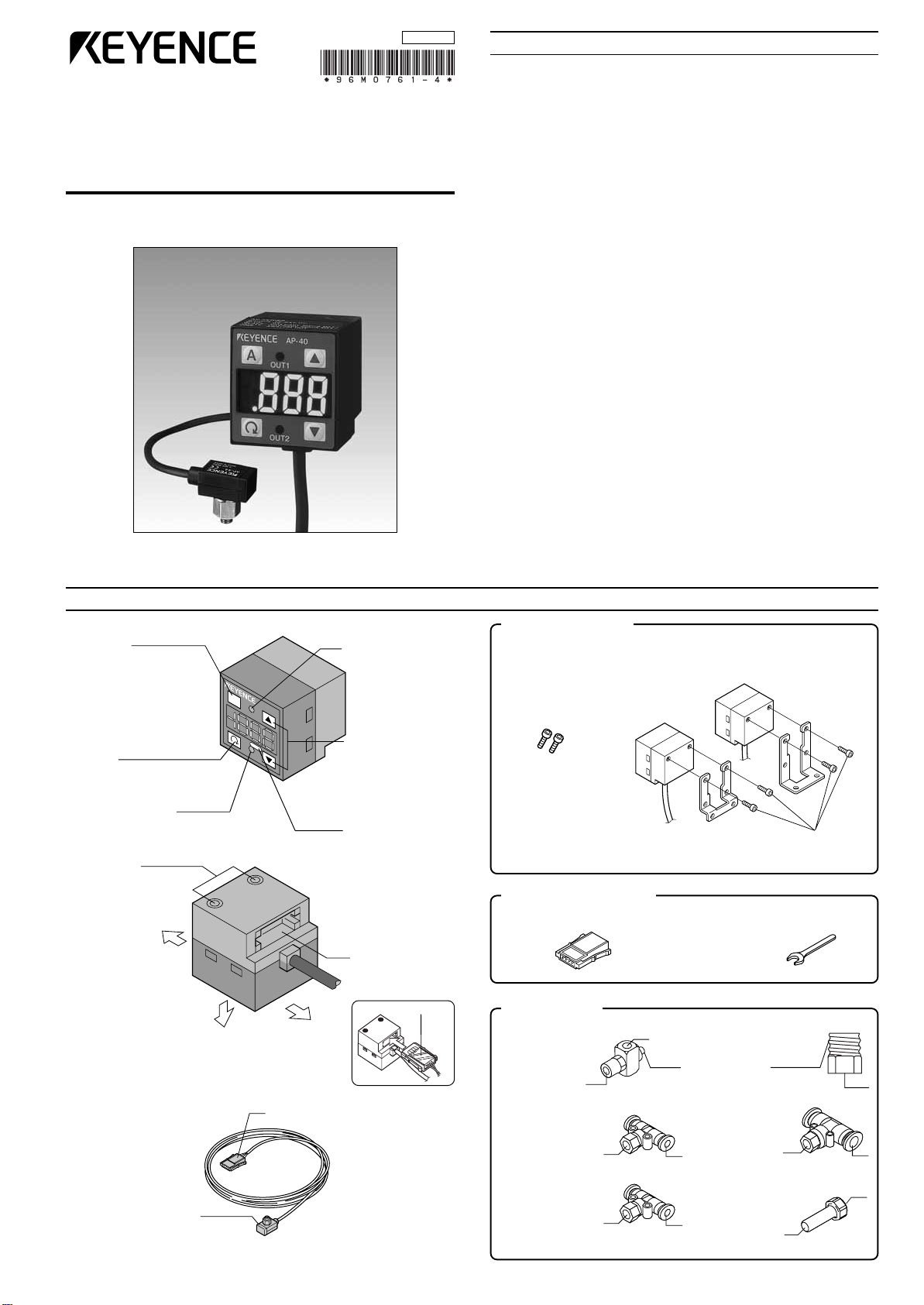
PART NAMES AND FUNCTIONS
■ Amplifier
AUTO key
In auto-tuning mode, use
this key to detect pressure. In measurement
mode, press this key for 2
seconds or more to adjust
the zero-point.
SET key
Use this key to display or
change preset values.
Output indicator 2
(Green LED)
Screw hole
Use this hole
to bolt the
mounting
bracket with
a hexagonal
socket bolt.
Top side
Front side
Bottom side
Output indicator 1
(Red LED)
UP/DOWN key
Use these keys to
set output modes,
or to change preset
values or units.
Display unit label
Connector port
Insert the sensor
head connector.
Connector cover
● Chattering prevention function
The instantaneous drops in base pressure due to the activation of a
large-bore ejector or other devices can be canceled. This eliminates
the need for preparing a sequence program.
● Automatic sensor head recognition function
When the power is turned on, the amplifier checks the sensor head
connection automatically. A recognized sensor head type appears
green on the display for 0.5 seconds.
● Industry's smallest and lightest sensor head (AP-41M)
This sensor head with half the volume of conventional models
weighs only 4.8 g, enabling flexible mounting.
● Zero-shift function (AP-40Z)
The current pressure value can be reset to 0 at any time in order to
prevent measurements from being affected by fluctuations in base
pressure.
Amplifier accessories
• Instruction
manual: 1
• Hexagonal
socket bolt: 2
Reference:
DIN-rail mounting or panel
mounting is also available.
(Optional brackets are
required.)
Sensor head accessories
Spare connector: 1 Mini-wrench: 1
Piping options
OP-33155
Screw pipe joint
•Mounting
bracket A: 1
(for AP-41M only)
OP-35388
PT 1/8
conversion
joint
•Mounting
bracket B: 1
Hexagonal
socket bolts
■ Sensor head
Sensor head
AP-41(M)/43/44
Connector
OP-33156
T-shaped quickrelease joint (ø4)
OP-42220
T-shaped quick
release joint (M3)
M5
M3
OP-33157
T-shaped
quick-release
joint (ø6)
OP-33158
Reducer
1
Page 2
Orange
Brown
Blue
Gray
1
2
3
4
CAUTION
MOUNTING
Brown
Black or white
Blue
12 to 24 VDC
0 V
Load
Brown
Black or white
Blue
12 to 24 VDC
4.7 k Ω
0 V
Voltage output
Brown
Black
Blue
12 to 24 VDC
0 V
White
(Control output 1)
(Control output 2)
Load
Load
Pressure sensor main circuit
Over current
protection circuit
Blue
Pink
Pressure sensor
main circuit
12 to 24 VDC
3.3 k Ω
11 kΩ
Blue
Pink
Analog
output (+)
0 V
Protection
circuit
Pressure sensor
main circuit
CAUTION
CAUTION
Brown
Black or white
Blue
12 to 24 VDC
0 V
Load
Brown
Black or white
Blue
12 to 24 VDC
4.7 k Ω
0 V
Voltage output
Brown
Black
Blue
12 to 24 VDC
0 V
White
(Control output 1)
(Control output 2)
Load
Load
Over current
protection circuit
Pressure sensor main circuit
■ AP-40/40Z/40P
As shown in the figure with "Amplifier accessories" on page 1, attach
the mounting bracket to the amplifier with hexagonal socket bolts.
The mounting bracket can be attached laterally according to the
location.
To avoid breakage, limit the tightening torque
for the hexagonal socket bolt to 0.3 N•m.
■ AP-41(M)/43/44
Limit the tightening torque for the screw hole of
the sensor head to 0.3 N•m.
■ Zero-point adjustment
At normal atmospheric pressure (1 atm.), press A for at least 2
seconds in measurement mode. The display changes to “----”, then to
“0”. The zero adjustment function can be used when the pressure is
within ±5% of F.S.
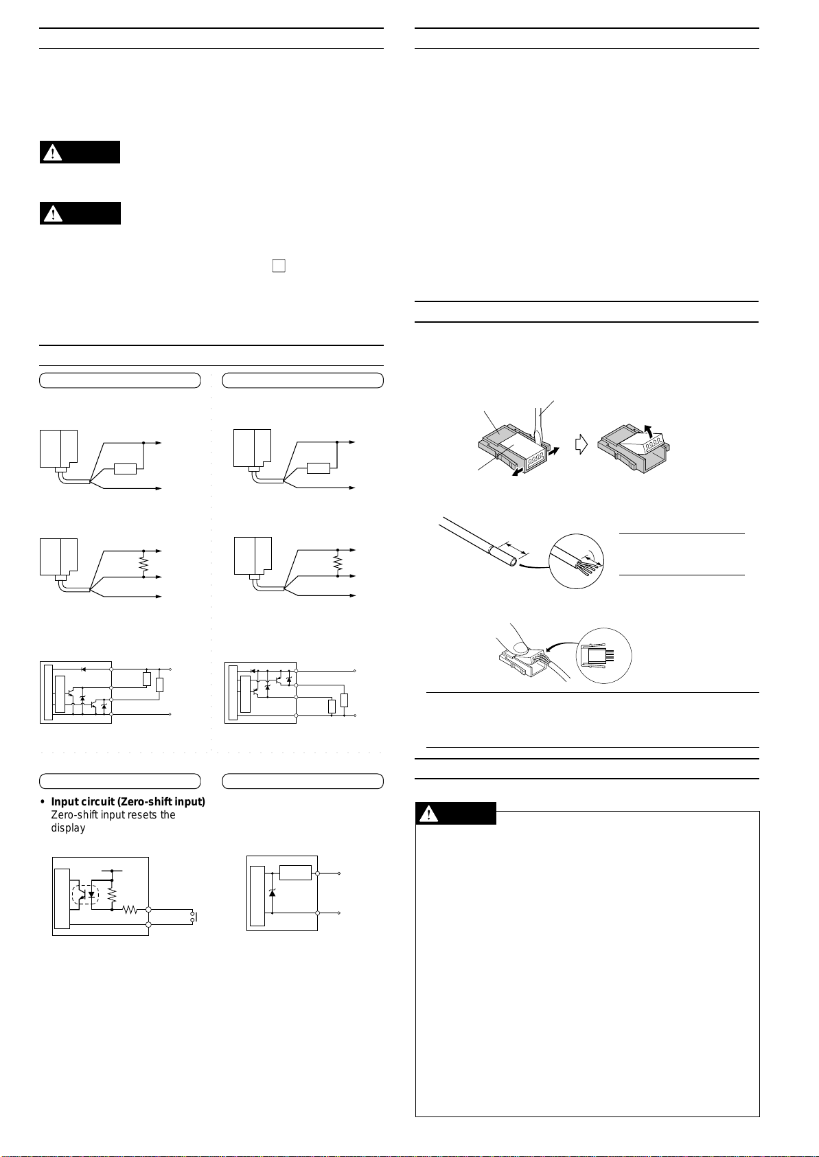
CONNECTIONS AND INPUT/OUTPUT CIRCUIT
AP-40/40Z AP-40P
■ Connections
• Drive current load • Drive current load
○○○○○○○○○○○○○○○○○○○○○○○○○○○○○○○○○○○
BASIC OPERATION
Basic operation (See also "ADJUSTMENT" on page 4.)
<Example>
● Checking the suction condition
1. Select F-3 (2-independent mode) and return to the measurement
mode.
➮ Refer to the setting in "Operation Mode" on the left-hand side of page 4.
2. Enter the target pressure value (A) and return to the measurement
mode. (You can specify another target pressure value (b).)
➮ Refer to the setting in "Preset Value Input Mode" on the right-hand side of
page 4.
3. Start detection.
● Base pressure control
1. Select F-4 (Window mode) and return to the measurement mode.
➮ Refer to the setting in "Operation Mode" on the left-hand side of page 4.
2. Enter the upper (H) and lower (L) limit values of the allowable
pressure and return to the measurement mode.
➮ Refer to the setting in "Preset Value Input Mode" on the right-hand side of
page 4.
3. Start detection.
ATTACHING A SPARE CONNECTOR
Use the spare connector to change the length of the sensor head
cable. Cables as long as 10 m can be used.
1. If the connector cover is fitted into the connector body, open the
cover.
Connector body
Slotted screwdriver
2. Lift the end of the cover.
• Input to voltage input • Input to voltage input
equipment equipment
■ Input/output circuit
• Output circuit • Output circuit
○○○○○○○○○○○○○○○○○○○○○○○○○○○○○○○○
AP-40Z (Z type only)
• Input circuit (Zero-shift input)
Zero-shift input resets the
display to “0” at the rising edge
of the signal.
AP-40/40P (40/40P type only)
• Analog output circuit
Connector cover
1. Widen the gap.
2. Cut a cable to the appropriate length and strip off the sheath for
approximately 25 mm from the end.
Approx.
25 mm
Approx.
25 mm
Note: It is not necessary
to remove the sheath of
the core wire.
3. Insert the cables into the proper holes as deep as possible. Then,
press the connector cover into the body with pliers.
Reference:
Note 1: Do not allow the cable to protrude from the other end of the
connector cover.
Note 2: Ensure that the cables are inserted as far as they will go. If
the inserted length is insufficient, the press-fitting fails.
SAFETY PRECAUTIONS
Be sure to follow the instructions below to avoid malfunctions.
■ Connection
• When using a commercially available switching regulator, be sure
to ground the frame ground terminals.
• Isolate the sensor’s wiring from power lines or high-voltage lines;
otherwise, the sensor may malfunction due to noise interference.
• The amplifier becomes hot or breaks down due to improper wiring.
• The press-fitting is available only once for each sensor head
connector.
■ Notice about CE marking
• Attach the ferrite core (OP-87505) if you extend a sensor head
cable/ amplifier power cable to 3 m or more to use.
(Attachment position: within 100 mm from the amplifier unit of a
power cable, Number of turns: 2)
■ Other
• Do not use the AP-40 Series for the detection of corrosive gases
or liquid.
• Do not insert any objects, such as wires, from the pressure port.
The pressure-sensing element may break, resulting in malfunctions.
• Do not press the front panel keys with a pointed object.
• The AP-40 Series does not have an explosion-proof structure.
Do not use it for the detection of flammable gases.
2
Page 3

noitacidnirorrEmelborPydemeR
sawtnemtsujdatniop-oreZ
foerusserpatadetucexe
± .S.Ffoeromro%5
tniop-orezmrofreP
lamrontatnemtsujda
.erusserpcirehpsomta
1TUOhguorhttnerrucrevO
2ro
tsujdadnafforewopnruT
tnerrucehttahtosdaoleht
.egnardetarehtnihtiwsi
sawerusserpdeilppA
.egnaryalpsidehtfoedistuo
(* FF ro FF- nehwsraeppa
siedomsucoftfihs-orezeht
).desu
nihtiwoterusserpehttsujdA
.egnardetareht
tonsidaehrosnesehT
gnitcennocehtrodetcennoc
.kaerbasahelbac
daehrosnesehttcennoC
.niagarewopehtnonrutdna
A
SH
Preset value C
SL
b
0
ON
OFF
ON
OFF
Control output 1
(OUT 1)
Control output 2
(OUT 2)
Pressure
Preset value H
H-h
0
ON
OFF
ON
OFF
Control output 2
(OUT 2)
h
Control output 1
(OUT 1)
Pressure
Preset value A
Preset value b
0
ON
OFF
ON
OFF
Control output 2
(OUT 2)
Control output 1
(OUT 1)
Pressure
Preset value H
SH
SL
Preset value L
0
ON
OFF
ON
OFF
Control output 1
(OUT 1)
Control output 2
(OUT 2)
Pressure
OTHER FUNCTIONS
▼
1 MPa
Atmospheric
pressure
Zero-shift input
Zero-shift input
-0.1 MPa is
acceptable.
-0.6 MPa is
not acceptable.
V1otV5
)M(14-PA 0otaPk3.101-
34-PA 0otaPM000.1+
44-PA 3.101+otaPk3.101–
■ Zero-shift function (AP-40Z type only)
The zero-shift function is used to reset the current pressure value to
“0” using an external signal input, in order to prevent measurements
from being affected by fluctuations in base pressure.
Example: Leakage test
Input a zero-shift value after
air supply is completed so
that air leakage after a
specified time is displayed
as a negative value. The
AP-40’s detection is
unaffected by fluctuations in air supply volume.
When the power is turned off, the value updated after the zero-shift
input (zero-shift value) is lost.
Note 1: The zero-shift function cannot be used in auto-tuning mode.
Note 2: The zero-shift input is effective when the current pressure is
between -3% of F.S. and 100% of F.S. for a shift of 0 (P = 0).
Note 3: If the applied pressure is outside the range of -15% to 110% of
the rated pressure, “-FFF” or “ FFF” appears.
Note 4: The display range for the zero-shift focus mode is ±19.9%.
When the pressure value is out of this range, “-FF” or “FF” is displayed.
■ Analog output function
(AP-40 only)
The voltage value according to the
pressure value is output.
■ Peak-hold/bottom-hold display function
The AP-40 Series internally updates the peak-hold and bottom-hold
values at all times.
● To display hold values
• While ▲ is held down in measurement mode, the peak-hold value
is displayed.
• While ▼ is held down in measurement mode, the bottom-hold
value is displayed.
● To reset the peak-hold and bottom-hold values
• Hold down ▲ and press ▼ in measurement mode.
● The peak-hold and bottom-hold values are also reset using the
following procedure.
• Turn the power off.
• Press for 3 seconds or more and change any settings.
Note: The hold values cannot be displayed when the front panel keys
are locked with the key protection function. Disable the function before
displaying the hold values.
■ Key protection
The key protection function is used to lock the front panel key in order
to prevent preset values from being accidentally changed.
To enable the key protection function, hold down A and press ▲.
“Loc” flashes for 2 seconds and the keys are locked.
To disable the key protection function, again hold down A and press
. “unL” flashes for 2 seconds and the keys are unlocked.
Using the EEPROM, the AP-40 Series can retain the preset values
even if the power is turned off.
■ Display color selection
You can set the color of the LED display either to the two-color mode
which displays the numerical value in green or red according to OUT1,
or to the single color mode which always shows the value in red or
green. The two-color display allows you to check the output condition
at a glance. (Refer to “ADJUSTMENT” on page 4 for the setting
procedure.)
In two-color mode (2-[) (Regardless of N.O./N.C. selection)
• When OUT1 is turned on: Red
• When OUT1 is turned off: Green
ERROR INDICATIONS AND REMEDIES
OPERATION MODE SELECTION
■ Auto-tuning mode (F-1)
Using the AUTO key, detect the upper limit value (A) and the lower
limit value (b). The detection level (C) is automatically set at the
midpoint between the two values. (You can finely adjust the preset
value C within the range between A and b.)
Control output 1: The sensor turns on when the pressure exceeds the
Control output 2: The sensor turns on when the pressure goes outside
■ Hysteresis mode (F-2)
Set desired detection level (H) and hysteresis (h) for the detection.
Control output 1: The sensor turns on when the pressure exceeds the
Control output 2: The sensor turns on when the pressure goes outside
■ 2-independent mode (F-3)
Set two desired detection points (A and B).
Control output 1: The sensor turns on when the pressure exceeds the
Control output 2: The sensor turns on when the pressure exceeds the
■ Window mode (F-4)
Set desired upper limit value (H) and lower limit value (L).
Control output 1: The sensor turns off when the pressure goes outside
Control output 2: The sensor turns off when the pressure goes outside
preset value C.
the stability levels.
* The stability levels are
automatically set as
shown in the following
calculations.
(A + C)
SH =
2
(C + b)
SL =
2
preset value H. When the pressure falls by the preset
value h, the sensor turns off.
the hysteresis width (H - h).
h: Hysteresis width of
OUT1
* When h is set to a
value close to 0, if
pressure fluctuates
around the detection
point, OUT1 will
chatter.
preset value A.
preset value b.
of the range between the upper limit value (H) and
lower limit value (L).
of the stability levels.
* The stability levels are
automatically set as
shown in the following
calculations.
Note 1: The above description shows the operation of control outputs
1 and 2 when the output selector switch is set to N.O.
SH = H –
SL = L +
(H - L)
4
(H - L)
4
When the output selector switch is set to N.C., the operation of control
outputs 1 and 2 is inverted.
Note 2: Except for OUT1 in hysteresis mode, each control output
includes an internal hysteresis of 0.5% of F.S.
3
Page 4

▼
▲
▲
ADJUSTMENT
dtS
,gHmm:44/)M(14-PA
mc/fgk:34-PA
2
AP
,aPk:44/)M(14-PA
aPM:34-PA
hcni
,gHhcni:44/)M(14-PA
:34-PAisP
RAb
rab:44/34/)M(14-PA
5.2
sm5.2
5
sm5
001
sm001
005
sm005
[-1
ylnoDELdeR
[-2
DELneerg/deR
tuptuonehwDER(
)NOsnrut1
❋ ❋ ❋ ❋
❋ ❋ ❋ ❋
❋ ❋ ❋ ❋
❋ ❋ ❋ ❋
❋ ❋ ❋ ❋
❋ ❋ ❋ ❋
• • •
• • •
• • •
• • •
A
A
(Measurement mode)
Current value
Flashes
alternately
Flashes
alternately
Flashes
alternately
Current upper
(lower) limit
value A
Current upper
(lower) limit
value b
The set value
C displays.
(C=
A + b
2
)
The updated value displays for 1 sec.
The updated value displays for 1 sec.
❋ ❋ ❋ ❋
❋ ❋ ❋ ❋
❋ ❋ ❋ ❋
• • •
• • •
1.
2.
3.
(Measurement mode)
Flashes
alternately
Current value
Flashes
alternately
Set the desired value
using
or
❋ ❋ ❋ ❋
Flashes
alternately
Set the desired value
using
or
• • •
1-F
edomgninut-otuA
3-F
tnednepedni-2
edomtuptuo
2-F
edomsiseretsyH
4-F
edomwodniW
Press the button
for 3 seconds or
more.
▲
Measurement mode
■ Unit Setting
Determine the desired units.
In measurement mode, press for at least 3 seconds. “- - - -”
appears first, and then the current units are displayed. Use ▲ or
to select the desired units. Pressing completes the unit
setting procedure and enters operation mode selection.
* When the units are changed, the preset values are automatically
converted to appropriate values for the updated units.
▲
Press the button once.
■ Operation Mode
Determine the desired operation mode.
(➮ Refer to “OPERATION MODE SELECTION” on page 3.)
The current operation mode is displayed. Use
the operation mode. Pressing completes the operation mode
setting procedure and enters N.O./N.C. selection.
or ▼ to select
Press the button
▲
▲
▲
once.
■ Preset Value Input Mode
Determine the preset values.
● Auto-tuning mode (F-1)
1. In measurement mode with the
current measured value displayed, press . The AP-40
enters the preset value input
mode.
2. “A” and the current preset value
flash alternately.
3. Position the target at the desired
upper (lower) limit.
4. Press A to register the value.
The updated value is displayed
for 1 second.
5. “b” and the current preset value
flash alternately.
6. Position the target at the desired
lower (upper) limit.
7. Press A to register the value. The updated value is displayed for 1
second.
8. “C” and the calculated preset value C flash alternately. (You can
change the C value to any value between A and b using ▲ or ▼.)
9. Press to register the C value. The setting procedure is completed and the unit returns to measurement mode.
* To confirm the preset value, press repeatedly.
▲
Press the button once.
■ N.O./N.C. Selection
Select N.O. (normally open) or N.C. (normally closed).
The current selection of “no” (normally open) or “nc” (normally
closed) is displayed. Use ▲ or ▼ to select the desired mode.
Pressing completes the N.O./N.C. selection procedure and
enters the chattering prevention setting.
▲
Press the button once.
■ Chattering Prevention
Determine the desired response time.
The current response time is displayed. Use ▲ or ▼ to select the
response time. Pressing completes the setting procedure and
enters the display color selection.
▲
Press the button once.
■ Display Color Selection
Determine the desired LED color for
numerical value display.
The current color is displayed. Use
or ▼ to select the color.
Pressing completes the setting
procedure and returns to the
measurement mode.
Press the button once.
* The setting is saved
in the EEPROM.
• Example of auto-tuning mode setting: Confirmation of work
piece pick-up.
Set the upper limit (A) to the position where the work piece is taken.
Set the lower limit (b) to the position where the nozzle becomes open
after releasing the work piece. Press A to register the upper and
lower limit values. The C value is automatically set to the midpoint
between the upper and lower limit values.
■ Hysteresis Mode (F-2), 2-independent Output
Mode (F-3), Window Mode (F-4)
1. In measurement mode with the
current measured value displayed,
press . The AP-40 enters the
preset value input mode.
2. “H” 1. and the current preset value
flash alternately.
3. Use ▲ or ▼ to change the value
to the desired value. Press to
register the updated H value.
4. “h” 2. and the current preset value
flash alternately.
5. Use ▲ or ▼ to change the value
to the desired value. Press to
register the updated h value.
6. “P” 3. and the shift value of the
zero-shift adjustment flash
alternately.
8. Press to complete the setting procedure and return to measurement mode.
* To confirm the preset value, press repeatedly.
[Example: In hysteresis mode]
1. “A” appears in the 2-independent
output mode.
2. “b” appears in the 2-independent
output mode.
“L” appears in the window mode.
3. Shown with Z type only.
Press the button once.
* The setting is saved
in the EEPROM.
Note 1: When the operation mode is changed, check the preset values
in the preset value input mode.
Note 2: Perform the zero-shift adjustment periodically.
Note 3: The initial output voltage may fluctuate by ±1.0% immediately
after the power is turned on. To measure minute differences in
pressure, let the sensor warm up for approximately 15 to 30 minutes.
Note 4: The amount of zero shift ("P") is displayed without multiplication even in the zero-shift focus mode.
4
Page 5

SPECIFICATIONS
ledoMM14/14-PA34-PA44-PA
erusserpdetaR
aPk3.101-ot0
)gHmm067-ot0(
aPM1ot0
mc/fgk01ot0(
2
)
otaPk3.101+
aPk3.101–
)gHmm067-ot067(
erusserpfoorP aPk005aPM5.1aPk005
sepytdiulF sesagevisorrocnonroriA
epyterusserP erusserpeguaG
ytilibataepeR
± .xam.S.Ffo%2.0
)reifilpmagnidulcni(
erutarepmeT
noitautculf
± .xam.S.Ffo%2
tropnoitcennoC
retemaid
wercselam5M
)ylnoM14-PAehtrofwercselam3M(
erutarepmettneibmA 05ot0 ° 221ot23(C ° gnizeerfoN,)F
ytidimuhevitaleR noitasnednocoN,%58ot53
noitarbiV
,Y,Xniedutilpmaelbuodmm5.1,zH55ot01
ylevitcepsersruoh4,snoitceridZdna
kcohS
s/m0001
2
ylevitcepsersemit01,snoitceridZdna,Y,Xni
)semit06:latoT(
lairetaM leetssselniatS:wercS,TBP:gnisuoH
thgieW
,)elbactuohtiw(g8.4:M14-PA
)elbacm3gnidulcni(g8.76
,)elbactuohtiw(g7:44/34/14-PA
)elbacm3gnidulcni(g07
ledoMP04/Z04/04-PA
ylppusrewoP CDV42ot21 ± .xam%01:)p-p(elppiR,%01
noitpmusnoctnerruC )daehrosnesgnidulcni()V42(Am55,)V21(Am501
yalpsiD
DELtnemges-7,roloc-2,tigid-2/13
.ces/semit5:elcycyalpsiD,)mm11:thgiehretcarahC(
egnarerusserpelbatceteD .S.Ffo%011+ot%51-
noituloseryalpsiD
,aPk1.0
,gHmm1
gHhcni1.0
rab100.0
aPM100.0
mc/fgk10.0
2
isP2.0
rab10.0
aPk2.0
gHmm2
gHhcni1.0
rab200.0
gnirettahc(emitesnopseR
)noitcnufnoitneverp
cesm005/001/5/5.2
tupnitfihs-oreZ
)ylnoepytZ(
eromrosm02:emittupnI
lortnoC
tuptuo
tuptuoNPN
,).xamV04(.xamAm001:rotcelloc-nepoNPN
.xamV1:egatlovlaudiseR
)elbatceles.C.N/.O.N(tuptuo-2
tuptuoPNP
,).xamV03(.xamAm001:rotcelloc-nepoPNP
.xamV1:egatlovlaudiseR
)elbatceles.C.N/.O.N(tuptuo-2
tuptuoegatlovgolanA
.1
V5ot1
rofnoitautculferutarepmeT
yalpsid
± .S.Ffo.xam%0.1
rofnoitautculferutarepmeT
tuptuogolana
.1
± .S.Ffo.xam%0.2
erutarepmettneibmA 05ot0 ° 221ot23(C ° gnizeerfoN,)F
ytidimuhevitaleR noitasnednocoN,%58ot53
noitarbiV
,Y,Xniedutilpmaelbuodmm5.1,zH55ot01
ylevitcepsersruoh2,snoitceridZdna
kcohS s/m001
2
ylevitcepsersemit3,snoitceridZdna,Y,Xni
lairetaM
,TEP:teehslenaptnorF,edimayloP:gnisuohtnorF
erytbacfoorp-liO:elbaC,enoflusyloP:gnisuohraeR
elbac
gnitnuoM
ro)sepyt2(tekcarbgnitnuomdeilppushtiW
tekcarbgnitnuomlenaplanoitpo
.2
thgieW )elbactuohtiwg82()elbacm2gnidulcni(g08
31
(4)
33
31
Cable length: 2 m
ø4 (5 x 0.18 mm
2
)
2 x M3 screw
20
26
40
t=1.5
2-ø4.5
mounting hole
25
6
16
22
31
45.5
t=1.5
2-ø4.5
4-ø3.5
45
14
20
30
25
16
22
35
19
20
t=1.5
2-ø4.5
4-ø3.5
14
20
20
13
30
45
8.6
19
20
t=1.5
31
20
45.5
13
31
M5 screw
Cable length: 3 m
(oil-resistant, flexible type)
ø3.6 (4 x 0.18 mm
2
core)
20 135.5
10
10
9
12
5
Cable length: 3 m
(oil-resistant, flexible type)
ø3.6 (4 x 0.18 mm
2
core)
19
9.8 9.2
0.9
617.3
10.3
M3 x 0.5
4
0.5
6.7
j
Copyright (c) 2001 KEYENCE CORPORATION. All rights reserved.
0761E 1022-4 96M0761 Printed in Japan
Sensor head
DIMENSIONS
AP-40/40Z
Unit: mm
Amplifier
When mounting
bracket A is attached
[Top view]
Mounting bracket A
(Accessory)
AP-41M
When mounting
bracket B is attached
[Side view]
Mounting bracket B
(Accessory)
1. Not provided with the AP-40Z.
2. Optional panel mounting brackets: OP-31357 (black), OP-32808 (gray) and OP-42192
(for a 5 mm-thick panel)
WARRANTIES AND DISCLAIMERS
KEYENCE, at its sole option, will refund, repair or replace at no charge any
defective Products within 1 year from the date of shipment. Unless stated
otherwise herein, the Products should not be used internally in humans, for
human transportation, as safety devices or fail-safe systems. EXCEPT FOR
THE FOREGOING, ALL EXPRESS, IMPLIED AND STATUTORY
WARRANTIES, INCLUDING WARRANTIES OF MERCHANTABILITY,
FITNESS FOR A PARTICULAR PURPOSE AND NONINFRINGEMENT OF
PROPRIETARY RIGHTS, ARE EXPRESSLY DISCLAIMED. KEYENCE
SHALL NOT BE LIABLE FOR ANY DIRECT, INDIRECT, INCIDENTAL,
CONSEQUENTIAL OR OTHER DAMAGES, EVEN IF DAMAGES RESULT
FROM THE USE OF THE PRODUCTS IN ACCORDANCE WITH ANY
SUGGESTIONS OR INFORMATION PROVIDED BY KEYENCE. In some
may not apply.
urisdictions, some of the foregoing warranty disclaimers or damage limitations
AP-41/43/44
E 1101-3
5
 Loading...