

Page 1
Brown
Black or white
Blue
12 to 24 VDC
0 V
Load
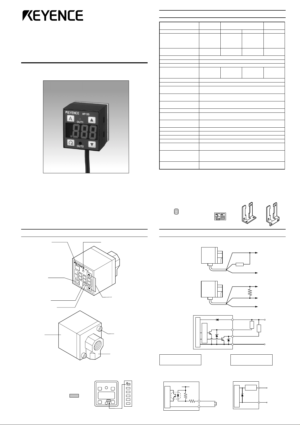
SPECIFICATIONS
Two-color Digital Display
Pressure Sensor
AP-30 Series
Instruction Manual
epyT
.1
ledoM
erusserpdetaR
erusserpfoorP
epyterusserP erusserpeguaG
sepytdiulF sesagevisorrocnonroriA
yalpsiD )mm11:thgiehretcarahC(DELtnemges-7,roloc-2,tigid-2/13
noituloseryalpsiD
ytilibataepeR ± )eromrosm5(.S.Ffo%2.0
tupnitfihs-oreZ
tuptuolortnoC
tuptuogolanA
yalpsidrof
ylppusrewoP CDV42ot21 ± .xam%01:)p-p(elppiR,%01
noitarbiV
lairetaM
thgieW
egnarerusserpelbatceteD .S.Ffo%011+ot%51-
gnirettahc(emitesnopseR
)noitcnufnoitneverp
.2
.3
noitautculferutarepmeT
tuptuogolanarof
noitautculferutarepmeT
noitpmusnoctnerruC )V21ta(Am09,)V42ta(Am05
erutarepmettneibmA 05ot0 °C
ytidimuhevitaleR %58ot53
)elbacm2gnidulcni(
evitageN
erusserp
)Z(13-PA)Z(23-PA)Z(33-PA)Z(43-PA
aPk3.101-ot0
067-ot0(
)gHmm
aPk094
2
mc/fgk5(
)
,aPk1.0
,gHmm1
isP20.0
± 52taerusserpgnitcetedfo).S.Ffo(.xam%2 ° 05ot0(C ° )C
± 52taerusserpgnitcetedfo).S.Ffo(.xam%1 ° 05ot0(C ° )C
1ot0(
2
mc/fgk
)
aPk094
2
mc/fgk5(
)
,aPk1.0
mc/fgk100.0
isP20.0
erusserpevitisoP
aPk0.001ot0
2
,
aPM000.1ot0
01ot0(
mc/fgk2)
aPM74.1
2
mc/fgk51(
)
,apM100.0
2
mc/fgk10.0
,
isP2.0
)elbatceles(sm005/001/5/5.2
eromrosm02:emittupnI
k74:ecnadepmidaoL(V5ot1 Ω ).nim
elbacerytbacfoorp-liO:elbaC
g021.xorppA
1. The zero-shift type sensor is suffixed with Z after the model name.
2. Z type only. 3. Not provided with Z type
dnuopmoC
erusserp
ot3.101+
aPk3.101–
gHmm067+(
)gHmm067-ot
aPk094
2
mc/fgk5(
)
,aPk2.0
,gHmm2
isP40.0
,)etats-dilos,tcatnoc(tupniegatlov-noN
laudiseR,).xamV04(.xamAm001:rotcelloc-nepoNPN
)elbatceles.C.N/.O.N(tuptuo-2.xamV1:egatlov
,Y,Xniedutilpmaelbuodmm5.1,zH55ot01
ylevitcepsersruoh2,snoitceridZdna
,TEP:teehslenaptnorF,edimayloP:gnisuohtnorF
,cniztsac-eiD:troperusserP,enoflusyloP:gnisuohraeR
PART NAMES AND FUNCTIONS
AUTO key
In auto-tuning mode, use
this key to detect pressure. In measurement
mode, press this key for 2
seconds or more to adjust
the zero-point.
SET key
Use this key to display or
change preset values.
Output indicator 2
(Green LED)
Display unit label
Housing
■Display unit label
The AP-30 series enables you to
select the display units for pressure.
Attach the included display unit label
for the desired units at the
position in the figure.
A
Output indicator 1
(Red LED)
UP/DOWN key
Use these keys to
set output modes,
or to change preset
values or units.
Hexagonal
socket bolt
Rear metal casing
(Die-cast zinc)
■ACCESSORIES
• Instruction manual: 1
• Hexagonal-socket
port stopper: 1
• Display unit
label sheet: 1
• Quick reference
sheet: 1
Mounting
bracket A: 1
Mounting
bracket B: 1
CONNECTIONS AND INPUT/OUTPUT CIRCUIT
■Connections
• Drive current load
• Input to voltage input equipment
■Input/output circuit
• Output circuit
Over current
protection circuit
Pressure sensor main circuit
AP-31Z/32Z/33Z/34Z
(Z type only)
Input circuit (Zero-shift input)
Zero-shift input resets the display to
“0” at the rising edge of the signal.
12 to 24 VDC
3.3 k Ω
Pink
Blue
Pressure sensor
main circuit
11 kΩ
Brown
Black or white
Blue
Brown
Black
(Control output 1)
White
(Control output 2)
Blue
AP-31/32/33/34
(Except for Z type)
Analog output circuit
Pressure sensor
main circuit
Protection
circuit
12 to 24 VDC
4.7 k Ω
Load
Voltage output
0 V
12 to 24 VDC
Load
0 V
Pink
Analog
output (+)
Blue
0 V
Page 2
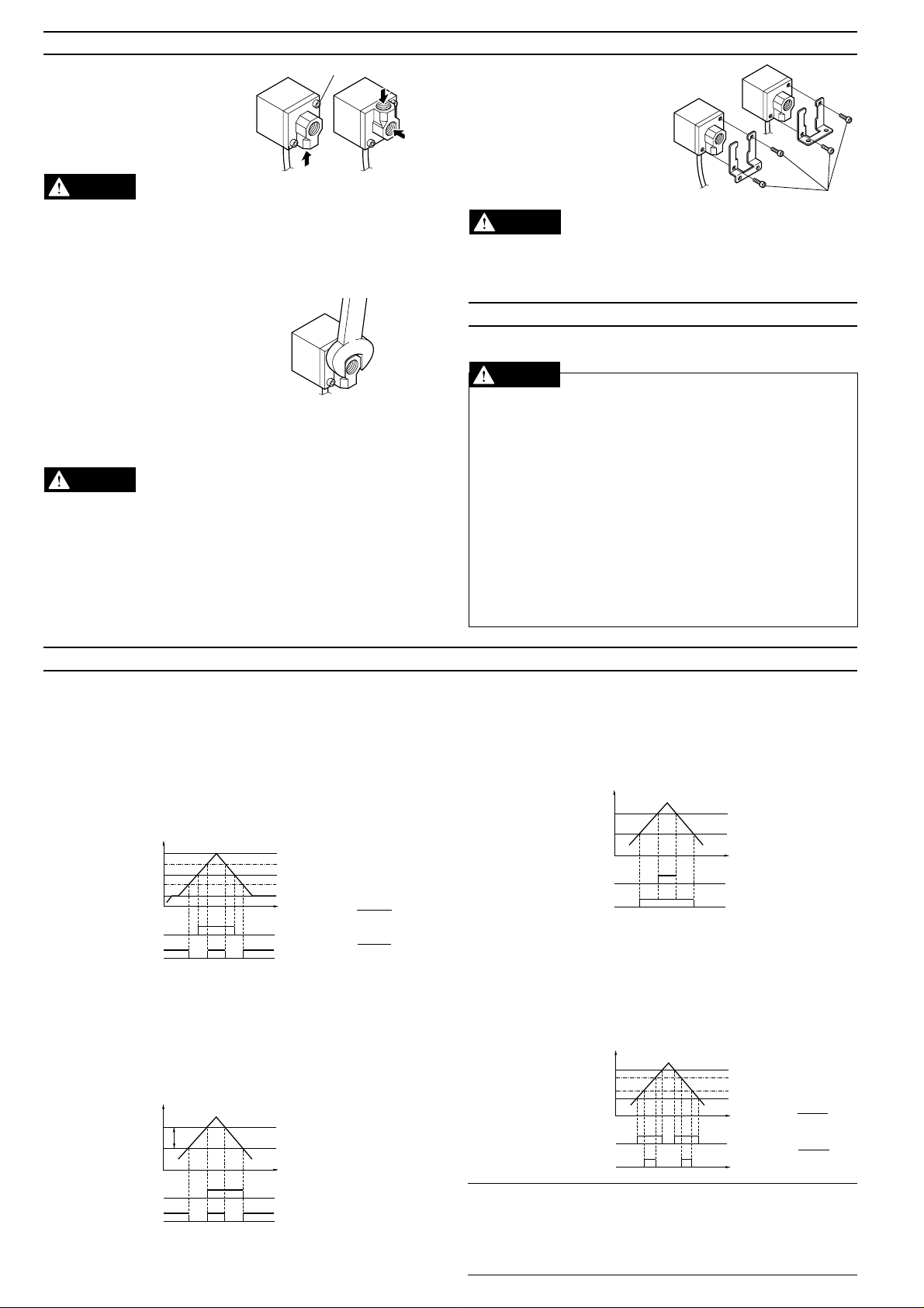
PIPING/MOUNTING
CAUTION
CAUTION
Preset value A
Preset value b
0
ON
OFF
ON
OFF
Control output 2
(OUT 2)
Control output 1
(OUT 1)
Pressure
Preset value H
SH
SL
Preset value L
0
ON
OFF
ON
OFF
Control output 1
(OUT 1)
Control output 2
(OUT 2)
Pressure
• You can select from three
pressure port positions by
selecting or replacing the
pressure ports. Select the
optimal position based on
your location.
CAUTION
* The arrow shows the pressure port
positions that can be selected.
The maximum tightening torque for the hexagonal socket bolt is
0.3 Nm (Approx. 3 kgf•cm). To avoid breakage, do not exceed the
specified value.
• An Rc (PT) 1/8 internal thread is provided on the pressure port of
the AP-30 series. Commercially available air-pressure pipe joints or
nipples can be used.
• When connecting a joint or a plug,
use a wrench (14 mm) to hold the
metallic part as shown in the figure to
avoid a large force being applied to
the sensor housing (resin part).
• Be sure to block an unused pressure port with the hexagonal-socket
port stopper provided.
CAUTION
The maximum tightening torque for the hexagonal-socket port
stopper is 10 Nm (Approx. 100 kgf•cm). To avoid breakage, do not
exceed the specified value.
• To prevent air leaks, wrap the male screw with sealing tape.
• To mount the AP-30 series to a panel using the panel mounting
holder set (OP-31357), use a panel with 1 to 3.5 mm thickness.
Hexagonal socket bolt
Hold this part with a
wrench (14 mm).
• Special mounting brackets are
included with the AP-30 series.
Use the type of mounting bracket
appropriate for the location
where the sensor is mounted. To
mount the sensor, remove the
hexagonal socket bolts and then
retighten them through the
mounting bracket.
Hexagonal
socket bolts
The maximum tightening torque for the hexagonal socket bolt is
0.3 Nm (Approx. 3 kgf•cm). To avoid breakage, do not exceed the
specified value.
SAFETY PRECAUTIONS
Be sure to follow the instructions below to avoid malfunctions.
■Connection
• When using a commercially available switching regulator, be sure
to ground the frame ground terminals.
• Isolate the sensor’s wiring from power lines or high-voltage lines;
otherwise, the sensor may malfunction due to noise interference.
■Other
• Do not use the AP-30 series for the detection of corrosive gases
or liquid.
• Do not insert any objects, such as wires, from the pressure port.
The pressure-sensing element may break, resulting in malfunctions.
• Do not press the front panel keys with a pointed object.
• The AP-30 series does not have an explosion-proof structure.
Do not use it for the detection of flammable gases.
OPERATION MODE SELECTION
■Auto-tuning mode (F-1)
Using the AUTO key, detect the upper limit value (A) and the lower
limit value (b). The detection level (C) is automatically set at the
midpoint between the two values. (You can finely adjust the preset
value C within the range between A and b.)
Control output 1: The sensor turns on when the pressure exceeds the
Control output 2: The sensor turns on when the pressure goes outside
Control output 1
Control output 2
■Hysteresis mode (F-2)
Set desired detection level (H) and hysteresis (h) for the detection.
Control output 1: The sensor turns on when the pressure exceeds the
Control output 2: The sensor turns on when the pressure goes outside
Control output 1
Control output 2
preset value C.
the stability levels.
Pressure
Preset value C
(OUT 1)
OFF
(OUT 2)
OFF
SH
ON
ON
A
SL
b
0
* The stability levels are
automatically set as
shown in the following
calculations.
SH =
SL =
preset value H. When the pressure falls by the preset
value h, the sensor turns off.
the hysteresis width (H - h).
Pressure
Preset value H
H-h
ON
(OUT 1)
OFF
ON
(OUT 2)
OFF
h
0
h: Hysteresis width of
OUT1
* When h is set to a
value close to 0, if
pressure fluctuates
around the detection
point, OUT1 will
chatter.
(A + C)
2
(C + b)
2
■2-independent mode (F-3)
Set two desired detection points (A and B).
Control output 1: The sensor turns on when the pressure exceeds the
preset value A.
Control output 2: The sensor turns on when the pressure exceeds the
preset value b.
■Window mode (F-4)
Set desired upper limit value (H) and lower limit value (L).
Control output 1: The sensor turns off when the pressure goes outside
Control output 2: The sensor turns off when the pressure goes outside
Note 1: The above description shows the operation of control outputs
1 and 2 when the output selector switch is set to N.O.
When the output selector switch is set to N.C., the operation of control
outputs 1 and 2 is inverted.
Note 2: Except for OUT1 in hysteresis mode, each control output
includes an internal hysteresis of 0.5% of F.S.
of the range between the upper limit value (H) and
lower limit value (L).
of the stability levels.
* The stability levels are
automatically set as
shown in the following
calculations.
SH = H –
SL = L +
(H - L)
4
(H - L)
4
Page 3

ADJUSTMENT
Press the button
for 3 seconds or
more.
■Unit Setting
Determine the desired units.
In measurement mode, press
appears first, and then the current units are displayed. Use ▲ or
to select the desired units. Pressing completes the unit
▼
setting procedure and enters operation mode selection.
dtS
isp
■Operation Mode
Determine the desired operation mode.
(➮ Refer to “OPERATION MODE SELECTION” on page 2.)
The current operation mode is displayed. Use ▲ or ▼ to select
the operation mode. Pressing completes the operation mode
setting procedure and enters N.O./N.C. selection.
1-F
3-F
■N.O./N.C. Selection
Select N.O. (normally open) or N.C. (normally closed).
The current selection of “no” (normally open) or “nc” (normally
closed) is displayed. Use ▲ or ▼ to select the desired mode.
Pressing completes the N.O./N.C. selection procedure and
enters the chattering prevention setting.
■Chattering Prevention
Determine the desired response time.
The current response time is
displayed. Use ▲ or ▼ to select
the response time. Pressing
completes the setting procedure and
enters the display color selection.
■Display Color Selection
Determine the desired LED color for numerical value display.
The current color is displayed. Use ▲ or ▼ to select the color.
Pressing completes the setting procedure and returns to the
measurement mode.
[-1
[-2
edomtuptuo
ylnoDELdeR
DELneerg/deR
▲
for at least 3 seconds. “- - - -“
,gHmm:43/13-PA
AP
2
mc/fgk:33/23-PA
* When the units are changed, the preset
values are automatically converted to
appropriate values for the updated units.
Press the button once.
▲
edomgninut-otuA
2-F
tnednepedni-2
4-F
Press the button once.
▲
Press the button once.
▲
Press the button once.
▲
5.2
5
001
005
,aPk:43/23/13-PA
aPM:33-PA
edomsiseretsyH
edomwodniW
sm5.2
sm5
sm001
sm005
Measurement mode
▲
▲
■Preset Value Input Mode
Determine the preset values.
● Auto-tuning mode (F-1)
1. In measurement mode with the
current measured value displayed, press . The AP-30
enters the preset value input
mode.
2. “A” and the current preset value
flash alternately.
3. Position the target at the desired
upper (lower) limit.
4. Press A to register the value.
The updated value is displayed
for 1 second.
5. “b” and the current preset value
flash alternately.
6. Position the target at the desired
lower (upper) limit.
7. Press A to register the value. The updated value is displayed for 1
second.
8. “C” and the calculated preset value C flash alternately. (You can
change the C value to any value between A and b using ▲ or ▼.)
9. Press to register the C value. The setting procedure is completed
and the unit returns to measurement mode.
* To confirm the preset value, press repeatedly.
• Example of auto-tuning mode setting: Confirmation of work
piece pick-up.
Set the upper limit (A) to the position where the work piece is taken.
Set the lower limit (b) to the position where the nozzle becomes open
after releasing the work piece. Press A to register the upper and
lower limit values. The C value is automatically set to the midpoint
between the upper and lower limit values.
■Hysteresis Mode (F-2), 2-independent Output
Mode (F-3), Window Mode (F-4)
1. In measurement mode with the
current measured value displayed,
press . The AP-30 enters the
preset value input mode.
2. “H” 1. and the current preset value
flash alternately.
3. Use ▲ or ▼ to change the value
to the desired value. Press to
register the updated H value.
4. “h” 2. and the current preset value
flash alternately.
5. Use ▲ or ▼ to change the value
to the desired value. Press to
register the updated h value.
6. “P” 3. and the shift value of the
zero-shift adjustment flash
alternately.
8. Press to complete the setting procedure and return to measure-
ment mode.
* To confirm the preset value, press repeatedly.
Note 1: In hysteresis mode, (h - F.S.) cannot be set to a value greater
than H.
Note 2: In window mode, (L + 1% of F.S.) cannot be set to a value
greater than H.
Press the button
once.
▲
(Measurement mode)
❋ ❋ ❋ ❋
Current value
• • •
❋ ❋ ❋ ❋
Current upper
(lower) limit
value A
❋ ❋ ❋ ❋
Current upper
(lower) limit
value b
❋ ❋ ❋ ❋
The set value
C displays.
A + b
(C=
2
A
A
• • •
❋ ❋ ❋ ❋
The updated value displays for 1 sec.
• • •
❋ ❋ ❋ ❋
The updated value displays for 1 sec.
• • •
Flashes
alternately
Flashes
alternately
Flashes
alternately
[Example: In hysteresis mode]
(Measurement mode)
❋ ❋ ❋ ❋
Current value
• • •
• • •
• • •
1. “A” appears in the 2-independent
output mode.
2. “b” appears in the 2-independent
output mode.
“L” appears in the window mode.
3. Shown with Z type only.
* The setting is saved
in the EEPROM.
Flashes
1.
alternately
❋ ❋ ❋ ❋
Set the desired value
using
or
Flashes
2.
alternately
❋ ❋ ❋ ❋
Set the desired value
using
or
Flashes
3.
alternately
❋ ❋ ❋ ❋
)
* The setting is saved
in the EEPROM.
●Zero-point adjustment
At normal atmospheric pressure (1 atm.), press A for at least 2
seconds in measurement mode. The display changes to “----“, then
to “0”. The zero adjustment function can be used when the
pressure is within ±5% of F.S.
Note 1: When the operation mode is changed, check the preset values in the
preset value input mode.
Note 2: When units of psi are selected with the AP-34Z, the display range
becomes 19.99 to 19.99.
Note 3: Perform the zero-shift adjustment periodically.
Note 4: The initial output voltage may fluctuate by ±1.0% immediately after the
power is turned on. To measure minute differences in pressure, let the sensor
warm up for approximately 15 to 30 minutes.
Page 4

OTHER FUNCTIONS AND ERROR INDICATION
6
■Zero-shift function (Z type only)
The zero-shift function is used to reset the current pressure value to
“0” using an external signal input, in order to prevent measurements
from being affected by fluctuations in base pressure.
Example: Leakage test
Input a zero-shift value after air supply is completed so that air leakage
after a specified time is displayed as a negative value. The AP-30’s
detection is unaffected by fluctuations in air supply volume.
Zero-shift input
1 MPa
Atmospheric
pressure
When the power is turned off, the value updated after the zero-shift
input (zero-shift value) is lost.
Note 1: The zero-shift function cannot be used in auto-tuning mode.
Note 2: The zero-shift input is effective when the current pressure is
between -3% of F.S. and F.S. for a shift of 0 (P = 0).
Note 3: If the applied pressure is outside the range of -15% to 110% of
the rated pressure, “-FFF” or “ FFF” appears.
■Key protection function
The key protection function is used to lock the front panel key in order
to prevent preset values from being accidentally changed.
To enable the key protection function, hold down A and press ▲.
“Loc” flashes for 2 seconds and the keys are locked.
To disable the key protection function, again hold down A and press
. “unL” flashes for 2 seconds and the keys are unlocked.
▼
Using the EEPROM, the AP-30 series can retain the preset values
even if the power is turned off.
■Display color selection
You can set the color of the LED display either to the two-color mode
which displays the numerical value in green or red according to OUT1,
or to the single color mode which always shows the value in red. The
two-color display allows you to check the output condition at a glance.
(Refer to “ADJUSTMENT” on page 3 for the setting procedure.)
In two-color mode (Regardless of N.O./N.C. selection)
• When OUT1 is turned on: Red
• When OUT1 is turned off: Green
Zero-shift input
-0.1 MPa is
acceptable.
-0.6 MPa is
not acceptable.
■Peak-hold/bottom-hold display function
The AP-30 series internally updates the peak-hold and bottom-hold
values at all times.
● To display hold values
• While ▲ is held down in measurement mode, the peak-hold value
is displayed.
• While
is held down in measurement mode, the bottom-hold value
▼
is displayed.
● To reset the peak-hold and bottom-hold values
• Hold down
and press ▼ in measurement mode.
▲
● The peak-hold and bottom-hold values are also reset using the
following procedure.
• Turn the power off.
• Press for 3 seconds or more and change any settings.
Note: The hold values cannot be displayed when the front panel keys
are locked with the key protection function. Disable the function before
displaying the hold values.
■Analog output function (Except for Z type)
The voltage value according to the pressure value is output.
ledoM V5otV1
13-PA aPk3.101-ot0
23-PA aPk0.001+ot0
33-PA aPM000.1+ot0
43-PA aPk3.101-ot3.101+
■Error indications and remedies
Error indication Problem Remedy
E
Ec
Zero-point adjustment was
executed at a pressure of
±5% or more of F.S.
Overcurrent through OUT1
or 2
Perform zero-point adjustment
at normal atmospheric
pressure.
Turn power off and adjust the
load so that the current is
within the rated range.
-FFF, FFF
Applied pressure was
outside of the display
Adjust the pressure to within
the rated range.
range.
■N.O./N.C. selection
The N.O. or N.C. output can be selected according to the device’s
control method. When the output status is changed, the color of the
numerical value display LED is inverted.
■Chattering prevention function
The chattering prevention function is used to prevent outputs from
chattering by changing the response time. The response time can be
selected from 4 settings. When the detection (non-detection) state
continues for more than a preset response time, the output is produced.
DIMENSIONS
AP-30 (Sensor unit)
31
33
(4)
Mounting bracket A
(Accessory)
16
22
20
19
Cable length: 2 m
ø4, 5 x 0.18 mm
25
35
30
20
2-ø3.5
14
2-ø4.5
t=1.5
2
core
8.5
31
24.5
6.5
Mounting bracket B
(Accessory)
20
19
45
Pressure port:
Rc (PT) 1/8
8.6
20
2 x M3 screw
14
20
6.5
30
20
2-ø3.5
14
20
2-ø4.5
13
45
t=1.5
When mounting bracket A is
attached
[Top view]
25
16.5
6
16
When mounting bracket B is
attached
31
45.5
20
2-ø4.5
mounting hole
31
[Side view]
31
22
t=1.6
13
t=1.
Worldwide Headquarters
KEYENCE CORPORATION
1-3-14, Higashi-Nakajima, Higashi-Yodogawa-ku,
Osaka, 533-8555, Japan
PHONE: 81-6-379-2211 FAX: 81-6-379-2131
KEYENCE CORPORATION OF AMERICA
PHONE: 201-930-0100 FAX: 201-930-0099
45
KEYENCE (UK) LIMITED
PHONE: 01908-696900 FAX: 01908-696777
KEYENCE DEUTSCHLAND GmbH
PHONE: 0711-7973710 FAX: 0711-7977799
KEYENCE FRANCE S.A.
PHONE: 01 47 92 76 76 FAX: 01 47 92 76 77
KEYENCE SINGAPORE PTE LTD
PHONE: 392-1011 FAX: 392-5055
KEYENCE SENSORS & MEASURING SDN BHD
PHONE: 03-252-2211 FAX: 03-252-2131
KEYENCE (THAILAND) CO., LTD
PHONE: 02-934-6772~4 FAX: 02-934-6775
KEYENCE KOREA CORPORATION
PHONE: 02-563-1270 FAX: 02-563-1271
© KEYENCE CORPORATION, 1998
Specifications are subject to change without notice.
AP3-IM-1-0398 Printed in Japan
 Loading...