

Page 1
Safety Interlocking
Important
Point
Reference
Important
DANGER
NOTICE
DANGER
96M15311
DANGER
DANGER
DANGER
DANGER
Switch
GS
(Non-contact)
Instruction Manual
• The GS (Non-contact) is designed with the assumption that
it would be correctly installed in accordance with the
installation procedures described in this manual and
correctly operated according to the instructions in this
manual. You must perform an appropriate installation of the
GS (Non-contact) after performing a sufficient risk
assessment for the target machine.
• Be sure to absolutely confirm that there is nobody in the
hazardous zone, before you remove the GS (Non-contact)
from the machine for replacement or disposal.
• When disposing the GS (Non-contact), always follow the
applicable requirements of the laws, rules, regulations and
standards in the country or region where the GS (Noncontact) is used.
• Dispose of this product as industrial waste.
Detailed information and use of the GS (Non-contact) is also described in
the "GS (Non-contact) User's manual". In order to acquire the "GS (Noncontact) User's manual", download it from the KEYENCE website or call the
nearest KEYENCE office.
<KEYENCE website> www.keyence.com/global.jsp
This manual explains items such as the handling, operation, and precautions
for the Safety Interlocking Switch GS (Non-contact). Read this manual
carefully and thoroughly understand its contents to use the GS (Non-contact)
to the full extent of its capabilities.
Also, keep this manual in a safe place for future reference.
Ensure that the end user of this product receives this manual.
This manual is the original instruction manual.
Symbols
It indicates a hazardous situation which, if not avoided, will
result in death or serious injury.
It indicates a situation which, if not avoided, could result in
product damage as well as property damage.
It indicates cautions and limitations that must be followed
during operation.
It indicates additional information on proper operation.
It indicates tips for better understanding or useful information.
Safety Precautions
General precautions
• KEYENCE does not guarantee the function or performance
of the GS (Non-contact) if it is used in a manner that differs
from the GS (Non-contact) specifications contained in this
manual or if the GS (Non-contact) is modified by the
customer.
• The GS (Non-contact) can only be used in combination with
dedicated actuators. It cannot be used in combination with
other actuators or similar devices.
• Do not bypass the GS (Non-contact), remove it or change its
installation orientation after installation.
• Do not use a replacement actuator to bypass the GS (Noncontact). Store replacement actuators strictly to prevent
their easy access.
• When using the GS (Non-contact) to protect machine
operators against a hazard or hazardous zone or when
using the GS (Non-contact) as a safety component for any
purpose, always follow the applicable requirements of the
laws, rules, regulations and standards in the country or
region where the GS (Non-contact) is used. For such
regulations, you should directly contact the regulatory
agency responsible for occupational safety and health in
your country or region.
• Depending on the type of machine on which the GS (Noncontact) is installed, there may be special safety regulations
related to the use, installation, maintenance, and operation
of the safety component. In such a case, you must fulfill
such safety regulations. The responsible personnel must
install the GS (Non-contact) in strict compliance with such
safety regulations.
• The responsible personnel must do the training to the
assigned personnel for the correct use, installation,
maintenance, and operation of the GS (Non-contact).
• The user of the machine must receive specialized training
related to the GS (Non-contact), and must then understand
and adhere to the safety restrictions, laws, and regulations
in the country or area in which the GS (Non-contact) is
being used.
• If the GS (Non-contact) does not operate correctly, the user
of the machine must report this information to the party
responsible for the use of the GS (Non-contact) and
immediately stop the machine.
Environment of use
• Do not use the GS (Non-contact) in an environment
(temperature, humidity, interfering light, etc.) that does not
conform to the specifications contained in this manual.
• Do not use a device that emits strong electromagnetic
waves near the GS (Non-contact).
• This product is not intended for use as an explosion-proof
product. Do not use this product in a hazardous location
and/or potentially explosive atmosphere.
• Do not use the GS (Non-contact) in the presence of
substances, such as heavy smoke, particulate matter, or
corrosive chemical agents, that may induce deterioration in
product quality.
• Be sure to absolutely confirm that there is nobody in the
hazardous zone, before the interlock is released (i.e. the
machine system restarts) by the interlock reset mechanism.
• Indoor use only.
Target machines for installation
• It must be possible to perform an emergency stop on the
machine to which the GS (Non-contact) is installed at any
and all operation points during the operation cycle. Also, do
not use the GS (Non-contact) on machines that have
irregular stop times.
• Do not use the GS (Non-contact) to control (stop forward
motion, etc.) trains, cars and other transportation vehicles,
aircraft, equipment for use in space, medical devices, or
nuclear power generation systems.
Circuit design and wiring
• Be sure to turn the power supply off before performing
electrical wiring.
• Perform electrical wiring according to the electrical
conventions, restrictions, standards, and laws in the
country or area in which the GS (Non-contact) will be used.
• Use cables with length less than or equal to the
specification in this manual. Usage of cables longer than
the specified value may cause the improper operation of
safety functions and may cause a dangerous situation.
Precautions on Regulations and Standards
CE Marking
KEYENCE Corporation has confirmed that this product complies with the
essential requirements of the applicable EU Directive(s), based on the
following specifications. Be sure to consider the following specifications when
using this product in the Member States of European Union.
• Machinery Directive
• RE Directive
The GS (Non-contact) is a safety component defined in the EU Machinery
Directive Annex V and has been certified by TÜV SÜD Product Service
GmbH. The GS (Non-contact) complies with the following EN Standards.
• EN 61508
• EN 62061
• EN ISO13849-1
• EN ISO14119
• EN 60947-5-3
• EN300 330
The full text of the EU declaration of conformity is available at the following
internet address: http://www.keyence.com/cedoc
• Frequency band of operation 123kHz
• Maximum radio-frequency power 60 dBμV/m
These specifications do not give any guarantee that the end-product with this
product incorporated complies with the essential requirements of RE and
Machinery Directive. The manufacturer of the end-product is solely
responsible for the compliance on the end-product itself according to these
Directives.
CSA Certificate and North American Regulations
The GS (Non-contact) complies with the following UL and CSA standards and
regulations, and has received CSA certification.
1
E GS (Non-contact) IM
Page 2
Applicable standards:
Reference
Highly visible
indicator
Detailed indicator
Main unit
Actuator
• CAN/CSA C22.2 No. 61010-1
• UL61010-1
Be sure to consider the following specifications when using this product as a
product certified by CSA.
• Overvoltage category II
• Pollution degree 3.
• Install this product at the altitude of 2000 m or less.
• Indoor use only.
• When using this product, use the following power supply. CSA or UL
certified power supply that provides Class 2 output as defined in the CEC
(Canadian Electrical Code) and NEC (National Electrical Code)
Applicable standard:
• FCC Part15 Subpart B, Class A Digital Device
• FCC Part15 Subpart C
• ICES-003, Class A Digital Apparatus
• RSS-210
This device complies with part 15 of FCC Rules and Innovation, Science and
Economic Development Canada's licence-exempt RSSs. Operation is subject
to the following two conditions: (1) this device may not cause harmful
interference, and (2) this device must accept any interference received,
including interference that may cause undesired operation.
Le présent appareil est conforme à la partie 15 des règles de la FCC et aux
normes des CNR d’Innovation, Sciences et Développement économique
Canada applicables aux appareils radio exempts de licence. L’exploitation
est autorisée aux deux conditions suivantes : (1)l’appareil ne doit pas
produire de brouillage, et (2) l’appareil doit accepter tout brouillage subi,
même si le brouillage est susceptible d’en compromettre le fonctionnement.
FCC CAUTION
Changes or modifications not expressly approved by the party responsible
for compliance could void the user’s authority to operate the equipment.
Note: This equipment has been tested and found to comply with the limits for
a Class A digital device, pursuant to part 15 of the FCC Rules. These limits
are designed to provide reasonable protection against harmful interference
when the equipment is operated in a commercial environment. This
equipment generates, uses, and can radiate radio frequency energy and, if
not installed and used in accordance with the instruction manual, may cause
harmful interference to radio communications. Operation of this equipment in
a residential area is likely to cause harmful interference in which case the user
will be required to correct the interference at his own expense.
Chapter 1 Before Operation
1-2 Product List
Main unit
For details on the main unit models, see “5-1 Model Number Description”
(page 7).
M12 connector type cables
z Standard cables
Use this cable in combination with a main unit (connector type), Y-shaped
connector, or extension cable.
Typ e Model Number of pins Length
GS-P5C5
Simple
function
Standard
Advanced
function
GS-P5C10 10 m
GS-P8C5
GS-P8C10 10 m
GS-P12C5
GS-P12C10 10 m
GS-P12C20 20 m
5
8
12
z Extension cables
Typ e Model Number of pins Length
GS-P5CC5
Simple
function
Standard
GS-P5CC10 10 m
GS-P8CC1
GS-P8CC5 5 m
GS-P8CC10 10 m
5
8
Mounting brackets
• GS-B01
• GS-B11
Optional parts
z Y-shaped connector
GS-Y01
z End connector
GS-Y02
z Replacement actuator
GS-A01
5 m
5 m
5 m
5 m
1 m
1-1 Overview and Configuration
The GS (Non-contact) is a Type4 Interlocking Device without guard lock
based on ISO14119.
Coding level: Low or high (switchable)
“4-6 Coding Level” (page 6)
By combining the GS (Non-contact) with a door or similar movable safety
guard and with a safety-related control system, it is possible to stop
hazardous machine operations if the door or similar part opens during
hazardous machine operations.
The GS (Non-contact) can also be used for other purposes such
as protecting manufacturing processes.
1-3 Package Contents
Main unit
• Sensor (main unit)
• Actuator
• Instruction Manual
E GS (Non-contact) IM
2
Page 3
Chapter 2 Installation
DANGER
DANGER
From the front From the side
Reverse orientation
Y
Z
X
Y
X
Y
Z
Y
Z
0
4
8
12
16
10-10-20-30 20 30
Y
X
0
16
4
8
12
-25
-20 -15 -10 -5 255 10 15 20
4
0
-4
-8
-12
-16
-20
-24
-28
8
12
16
20
24
28
4 8 1216
4812
-30
-27
-24
-21
-18
-15
-12
-9
-6
-3
0
3
6
9
12
15
Y
Z
X
ON area
Front installation
Side installation
60 mm or more
50 mm or more
60 mm or more
2-1 Installation Conditions
Note the following items before installation.
The effect of surrounding metal
The sensor’s operating distance may be affected by the
presence of metal in the surrounding area. After installation,
check that an appropriate safety distance based on the
detecting distance is used.
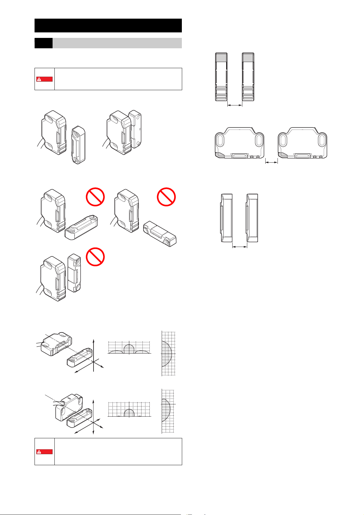
Sensor and actuator orientation
Correct installation orientations
Incorrect installation orientations
Mutual interference
When using multiple GS (Non-contact) units in close proximity, they may
malfunction due to mutual interference. To prevent mutual interference, install
the GS (Non-contact) units as shown below.
Distance between sensors
Distance between actuators
Operating area
• The above values indicate the recommended distance.
Check whether there are issues in the actual installation
environment.
• When installing the unit on a sliding door, do so at a distance
of 6 mm or more to prevent the effect of the side lobe.
3
E GS (Non-contact) IM
Page 4

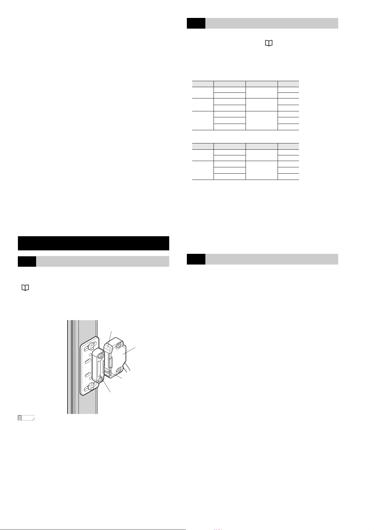
2-2 Installation Method
Reference
Important
DANGER
M4 screw
Tightening torque: 1.0 N⋅m
M4 screw
Tightening torque: 1.0 N⋅m
1
2
3
5
4
2
3
4
8
5
6
7
1
10
6
1
93
4
5
7
8
12
11
2
Installing the unit to a hinged door
1
Chapter 3 Wiring
3-1 Power Supply
If the power supply for the GS (Non-contact) is the converting type, the power
supply for the GS (Non-contact) must meet the conditions listed below in
order to meet the requirements specified in ISO 14119, IEC 60947-5-3, UL
61010-1, and CAN/CSA-C22.2 No. 61010-1.
(a) The rated output voltage is within 24 V DC ±20 % (Ripple P-P 10 % or
less, Class2, SELV, Overvoltage category II).
(b) The insulation between the primary and secondary circuits is reinforced or
double insulation.
(c) The power supply complies with the laws, regulations, and standards
related to items such as electrical safety and electromagnetic
compatibility (EMC) in the country or area in which the GS (Non-contact)
will be used.
When the power supply used with the GS (Non-contact) is
shared with other machines or electrical products, the voltage
supplied to the GS (Non-contact) may drop due to temporary
increases in the current consumption of these other machines
and the GS (Non-contact) may also be affected by the noise
generated by these other machines. Errors or other such
problems may occur with the GS (Non-contact) in this
situation, so it is strongly recommended to avoid sharing the
power supply of the GS (Non-contact) with other machines or
electrical products.
2
3-2 Cable Wire Colors and Functions
Simple function type (M12 connector, 5 pins)
Pin number Wire color Function
1 Brown +24 V
2 White OSSD2
3Blue 0 V
4 Black OSSD1
5 Gray AUX output1
Standard type (loose wires or M12 connector, 8 pins)
Pin number Wire color Function
1 Gray AUX output1
2 Brown +24 V
3 Light blue Not used
4 Red/white Safety input 2
5 Black OSSD1
6 White OSSD2
7Blue 0 V
8 Red/black Safety input 1
Advanced function type (loose wires or M12 connector, 12 pins)
• To minimize defeat possibilities, GS (Non-contact) should
be installed in a position where the accessibility to GS
(Non-contact) is prevented (e.g. mounting out of reach,
physical obstruction or shielding or mounting in hidden
position), otherwise use non-detachable fixing to prevent
dismantling or de-positioning of GS (Non-contact) (e.g.
Using a flat head screw and plugging the slot on the screw
head with a high-strength threadlocker after tightening the
screw or other equivalent fixing system).
Refer ISO 14119 for more information to minimize defeat
possibilities.
• Securely tighten the screws for the sensor, actuator, and
mounting brackets according to the specified tightening
torque.
• To prevent self-loosening, use screw locker on the screws
fixing the GS (Non-contact).
• When replacing the sensor or actuator, do so by following the
same procedure.
• The appropriate screws must be purchased separately.
Pin number Wire color Function
1 Brown +24 V
2 Red/black Safety input 1
3Blue 0 V
4 Black OSSD1
5 Gray AUX output 1
6 Red/white Safety input 2
7 White OSSD2
8 Pink Interlock/EDM selection input
9 Gray/black
10 Light blue
11 Yellow Reset/EDM input
12 Light blue/black
*1 This is not present on loose wire types.
*1
*1
*1
Not used
Not used
Not used
Pin layout (sensor main unit, M12 connector type)
Simple function
(M12, 5 pins, male)
Standard type
(M12, 8 pins, male)
Advanced function type
(M12, 12 pins, male)
2-3 Cascade Connection Between Units
Multiple GS (Non-contact) and GS (Lock) units can be connected in series (in
a cascade connection).
This makes it possible to monitor the opening and closing of multiple doors or
similar items on the same machine.
For the wiring method, see “Cascade connection wiring example” (page
5).
E GS (Non-contact) IM
4
Page 5

3-3 Wiring Example
4: Black (OSSD1)
7: White (OSSD2)
11: Yellow (reset/EDM input)
8: Pink (interlock/EDM selection input)
1: Brown (+24 V)
3: Blue (0 V)
5: Gray (AUX output 1)
2: Red/black (safety input 1)
6: Red/white (safety input 2)
4: Black (OSSD1)
7: White (OSSD2)
11: Yellow (reset/EDM input)
8: Pink (interlock/EDM selection input)
1: Brown (+24 V)
3: Blue (0 V)
5: Gray (AUX output 1)
2: Red/black (safety input 1)
6: Red/white (safety input 2)
K1 K2
K2
K1
S1-1
General-purpose PLC
K1 K2
K1, K2: External device (force guided relay, magnet
connector, etc.)
S1-1: Reset switch (N.O.)
1st unit
GS (Non-contact)
PNP output
Advanced function type
Interlock: Manual
EDM: Use
Cascade connection: Yes
2nd unit
GS (Non-contact)
PNP output
Advanced function type
Interlock: Automatic
EDM: Do not use
Cascade connection: No
Black or white
Blue
+24V
0 V
External device
Main
circuit
Brown
Brown
Black or white
Blue
+24 V
0 V
External device
Main
circuit
Brown
(Input wire)
Blue
+24 V
Main
circuit
0 V
Brown
(Input wire)
Blue
+24 V
0 V
Main
circuit
DANGER
Brown
(Output
wire)
Blue
+24 V
0 V
Input
device
Main
circuit
Cascade connection wiring example
Wire the safety inputs of a GS (Non-contact) to the OSSDs of the next GS
(Non-contact) or GS (Non-contact) to implement a cascade connection.
• “4-1 OSSD” (page 5)
• “4-2 Safety Input” (page 6)
Cable length and number of connected units (Standard)
B: Maximum number of connected units 30
Contact KEYENCE for the maximum number of connected units when using a
cascade connection that also includes GS (Lock) units.
3-4 I/O Circuit Diagrams
Output circuit (PNP type) Output circuit (NPN type)
Input circuit (PNP type) Input circuit (NPN type)
A: Maximum cable length 30.3 m
AUX output circuit (PNP/NPN common)
Chapter 4 Functions
The functions that can be used with the GS (Non-contact) vary depending on
the model of the main unit (simple function type/standard type/advanced
function type).
Simple function
type
Standard type
Number of pins 5 8 12 (*1)
OSSD
Safety input
Interlock function
EDM function
333
− 33
− −
− −
Number of AUX outputs 1 1 1
Coding level switching
333
*1 The loose wire type has nine cores.
4-1 OSSD
An OSSD output is a safety output for the safety-related part of a machine
control system.
OSSD 1/2 is a pair of safety outputs that are redundant.
The GS (Non-contact) generates self-diagnosis signals on its internal control
circuit to perform diagnostics on the OSSD. These signals periodically force the
OSSD into a temporary OFF-state when the OSSD is in the ON-state.
If the internal control circuit receives a feed-back signal (OFF-signal) based on
the self-diagnosis, the GS (Non-contact) determines that its OSSD is operating
normally. If the OFF-signal is not returned to the internal control circuit, the GS
(Non-contact) determines that there is a problem with the OSSD or wiring and
goes to an error state.
OSSD operation
The OSSDs go to OFF state:
• During startup, in the error state, when switching the coding level
When all the conditions shown below are met during normal operation, the
OSSDs go to ON state. (*1)
• The sensor has detected an actuator.
• Safety inputs are ON.
*1: The OSSDs go to OFF state in the interlock reset ready state.
• For the wiring to a safety-related machine control system,
the output of both OSSD 1 and OSSD 2 must be used by the
safety-related machine control system in order to create a
safety system.
• If only one OSSD output is used to construct the machine’s
control system, an OSSD malfunction will make it
impossible to stop the machine, which may lead to
extremely dangerous situations including serious injury to
or death of the machine’s user.
• When using a PNP sensor, do not cause a short-circuit
between the OSSD and +24V. Otherwise, the OSSDs will
stay in the ON-state and it will cause a dangerous situation.
• When using a PNP sensor, be sure to connect the load
between the OSSD and 0 V. Connecting this between the
OSSD and +24 V by mistake will invert the OSSD operation
from its normal behavior, which is extremely dangerous.
• When using an NPN sensor, do not cause a short-circuit
between the OSSDs and 0V. Otherwise, the OSSDs stay in
the ON-state and it will cause a dangerous situation.
• When using an NPN sensor, be sure to connect the load
between the OSSD and +24 V. Connecting this between the
OSSD and 0 V by mistake will invert the OSSD operation
from its normal behavior, which is extremely dangerous.
• To prevent malfunctions caused by ground faults on the
OSSD output wire, perform wiring in a manner such that the
requirements specified in paragraph 9.4.3 of IEC 60204-1
are met.
Advanced
function type
3
3
5
E GS (Non-contact) IM
Page 6

4-2 Safety Input
Point
Reference
Point
DANGER
Standard type
Advanced function type
Advanced function type
DANGER
DANGER
Advanced function type
This function controls the OSSDs of the GS (Non-contact) with input signals
from sensors or similar devices connected to the safety inputs.
Safety input 1 and safety input 2 form a safety input pair. If safety input 1 or
safety input 2 turns OFF, the OSSDs turn OFF.
Multiple GS units can be connected and used in an expanded system (with a
cascade connection) by connecting the OSSDs of a different GS (Noncontact) or GS (Lock) to the safety inputs. The system can be expanded to
include up to thirty units in the case of the GS (Non-contact).
The simple function type has no safety input.
• Wire the safety inputs as shown below when they are not in use.
PNP type: Short circuit to 24 V.
NPN type: Short circuit to 0 V.
• If safety input 1 and safety input 2 are mismatched for 3
seconds or more a Safety Input Error will occur.
Emergency stop switch/button wiring
Wiring an emergency stop switch/button to the safety inputs makes it
possible to perform an emergency stop on the machine by pressing the
emergency stop switch/button.
• Use an emergency stop switch/button that has two or more
independent, NC (normally closed) contacts. For the
requirements related to emergency stop switches, see IEC
60204-1, ISO 13850, and all other requirements, regulations,
standards, and laws related to occupational safety and
health in the country or area where the GS (Non-contact)
will be used. For such regulations, you should directly
contact the regulatory agency responsible for occupational
safety and health in your country or region.
• Ensure that the device does not start or restart automatically
when the emergency stop switch/button is reset.
• Only the devices shown below can be connected to the
safety inputs. Do not connect any other devices.
• GS (Non-contact) OSSDs, GS (Non-contact) OSSDs, and
emergency stop switch/button
• When using a PNP sensor, please connect the OSSDs of the
PNP type GS (Lock) or GS (Non-contact) to the safety
inputs.
• When using a NPN sensor, plesae connect the OSSDs of the
NPN type GS (Lock) or GS (Non-contact) to the safety
inputs.
4-3 Interlock Function
Interlock is a function that prevents the OSSDs from automatically going into
the ON-state from the OFF-state. This prevents the unintended start-up and/or
the unintended restart of the machine if the interlock is applied to the GS
(Non-contact). It is necessary to perform the reset operation in order for the
GS (Non-contact) to go back to normal operation from the interlock condition.
• Be sure to absolutely confirm that there is nobody in the
hazardous zone before the interlock condition is terminated
(i.e. the machine system restarts) by the interlock reset
mechanism.
• Install the switch, etc. for releasing the interlock state in a
position where it is possible to check the entirety of the
hazardous zone and where the switch, etc. cannot be
operated from within the hazardous zone.
• When the interlock function is set to Automatic, it is
necessary to ensure the safety of the entire control system in
order to prevent unexpected starts from occurring.
• Exercise caution to prevent the reset/EDM input from
forming a short circuit with other inputs or outputs.
4-4 EDM Function
The GS (Non-contact) can monitor the state of external devices, such as a
safety relay or contactors that are connected to the OSSDs, in order to detect
the failure of the external device. This monitoring function is called the EDM
function.
EDM function settings
Use the wiring to configure the settings. The wiring varies depending on
whether the interlock function is used. For details, see “4-3 Interlock
Function” (page 6).
4-5 AUX Output
This is an informational output used to check the operating status of the GS
(Non-contact).
The AUX outputs cannot be used as the safety outputs to a
safety-related control system.
4-6 Coding Level
The GS (Non-contact) has two coding levels.
Coding level: Low
(multi operation)
Coding level: High
(unique operation)
Any actuator is detected when it enters the range of
the operating distance from the sensor. (Initial setting)
Only the specific actuator that the sensor has been
taught to detect is detected when it enters the range of
the operating distance from the sensor. The sensor
does not respond if an actuator other than the actuator
that it has been taught to detect is within the range of
the operating distance.
The interlock function cannot be set on the simple function
type and standard type. The interlock function is fixed to
Automatic.
On the advanced function type, the interlock function setting can be selected
from two types: Automatic and Manual.
Automatic and Manual indicate the following operations.
Automatic:
The OSSDs immediately switches to the ON state when the conditions for
doing so—such as the door closed—are met.
Manual:
Even if the conditions for switching the OSSDs to the ON state are met, the
OSSDs maintain the OFF state (interlock state).
<Terminating the interlock state>
To set the OSSDs to the ON state and to start the machine, close the door to
which the GS (Non-contact) has been installed and perform the reset
operation after the preparations for starting the machine are complete. This
sets the OSSDs to the ON state and terminates the interlock state.
Interlock function settings
Use the wiring to configure the settings. The wiring method varies depending
on whether the “4-4 EDM Function” (page 6) is used.
Interlock
function
Automatic Do not use 0 V 0 V
Automatic Use
Manual Do not use
Manual Use
EDM
function
Reset/EDM input
Connected to 24 V via a relay
NC contact
Connected to 24 V via an NO
reset switch
Connected to 24 V via an NO
reset switch and a relay NC
contact
Interlock/
EDM function selection input
Open
Connected to 24 V
Connected to 24 V
E GS (Non-contact) IM
6
Page 7

Chapter 5 Specifications
GS - 1 1 P * 5
Cable length
C: M12 connector,
Blank: Loose wires
P: PNP, N: NPN
0: Simple function, 1: Standard, 3: Advanced function
1: Non-contact
* only necessary when using
loose wire connection
GS - P 5 C 5
Cable length
C: Standard cable
CC: Extension cable
5: 5 pins (simple function)
8: 8 pins (standard)
12: 12 pins (advanced function)
5-1 Model Number Description
Main unit
Cable
5-2 Specifications
Specifications
GS-
GS-
GS-
GS-
GS-
GS-
Model
Typ e
Output type PNP PNP NPN PNP NPN PNP PNP PNP
Operating
distance
Response
*1
time (ms)
Door
operation
Cascading
Control
output
(OSSD
output)
AUX
(Nonsafetyrelated
output)
External
input
(Shortcircuit
current)
Power
supply
Protection circuit
Environment
al resistance
Material
Weight
*1 Risk time according to IEC60947-5-3 is 150 ms + 2 ms × (number of cascaded units - 1).
*2 When AUX outputs of each unit are not used, it is possible to cascade up to 10 units.
*3 When stored for a long period of time, please store it at temperature of 55°C or lower.
Sao (OFF
→ ON)
Front
Sar (ON →
OFF)
Sao (OFF
→ ON)
Side
Sar (ON →
OFF)
Detect →
Not detect
Detection
Not detect
→ Detect
Acceptable operation
frequency
Standard - Max. 30 units
Using Y-shaped
connector
Output Transistor outputs × 2
Max. load current PNP: Max. 150 mA, NPN: Max. 100 mA
Residual voltage
(during ON)
OFF state voltage Max 2.0 V (with a cable length of 5 m)
Leakage current Max. 500 μA
Max. capacitive load 2 .2 μF
Load wiring resistance Max. 2.5 Ω
Output Transistor output
Number of output 1
Max. load current 50 mA
Residual voltage
(during ON)
Safety input - Approx. 1.5 mA × 2
Reset/EDM input -
Power voltage 24 V DC ±20 % (Ripple P-P 10 % or less, Class2)
Power consumption 0.8 W
Enclosure rating
Operating ambient
temperature
Storage temperature -25°C to +70°C (No freezing)
Operating relative
humidity
Storage relative
humidity
Vibration resistance
Shock resistance 30 G in X, Y, Z directions 6 times each axis (IEC 60947-5-3)
Case Zinc die cast (Nickel chrome plating), PBT, PAR
Sensor
main unit
Cable PVC
Actuator Case SUS430, SUS304, PBT
10PC
11P5
11N5
11P10
Simple
function
type
20 ms + 2 ms × (number of cascaded unit - 1)
30 ms + 25 ms × (number of cascaded unit - 1)
-
Max 2.5 V (with a cable length of 5 m)
Max 2.5 V (with a cable length of 5 m)
Reverse current protection, short-circuit protection and surge
IP65/67(IEC60529), IP69K(ISO20653) (TÜV SÜD certified)
5 minutes in each of the X, Y, and Z directions (IEC 60947-5-3)
Approx.
80 g
protection for each output
Enclosure Type 3/4X/12/13 (NEMA250)
-20°C to +55°C (No freezing)
10 to 55 Hz, Double amplitude 3.0 mm,
Approx. 270 g Approx. 480 g
11N10
Standard type
10 mm
18 mm
6 mm
14 mm
3 Hz
5% to 95%RH
5% to 95%RH
Safety-related parameters
Mission time 20 years
Hardware fault tolerance 1
Type of element B
Performance level e
Category 4
SIL 3
11PC
Max. 4
units
*3
Approx.
80 g
GS-
13P5
Advanced
function type
*2
Approx. 5.0 mA
Approx.
280 g
13PC
-
× 1
Approx.
GS-
80 g
PFH (IEC 61508)
Interlocking function 4.78×10
7
-10
E GS (Non-contact) IM
Page 8

Chapter 6 Appendix
OSSD
INPUT
READY
GS-11P5
(1) Highly visible indicator
(2) OSSD indicator
(3) INPUT READY indicator
3 (detection center)
5 38
15
5
30
ø5.2
2-4.2x9.2 through hole
7.4x12.4 depth of counterbore:
4.2 (both surfaces)
GS-13P5
Black, gray, red/white, red/black,
5.9
(detection center)
11.8
48
24
(detection center)
Unit: mm
38
5
7
2-ø4.2 through hole
ø8 depth of
counterbore: 4.2
12.5
5.9 (detection center)
11.8
48
Unit: mm
6-1 Indicator Descriptions
6-2 Dimensions
Direct mounting
Sensor main unit
(1) Highly visible indicator
Light
Status Details
color
Green ON During normal operation. ON Detected
Blinking
(fast)
Orange
Blinking
ON Door, etc. is open. OFF Not detected
Red
Blinking
OFF
-
During operation with the “High”
coding level, an actuator different
from the one that was taught was
detected.
Error during coding level switching Uncertain
Switching coding level or teaching
for an actuator
Error state. The GS (Non-contact)
has detected an error.
Power OFF. OFF Uncertain
(2) OSSD indicator
Light
Status Details
color
ON The OSSD is ON. ON Detected
Green
Blinking
Red ON The OSSD is OFF. OFF Uncertain
The OSSD is ON but the state is
unstable such as the door starting
to open.
(3) INPUT READY indicator
Light
Status Details
color
ON
Yellow
Blinking Safety inputs are OFF. OFF Uncertain
OFF
-
E GS (Non-contact) IM
Interlock release wait state (waiting
for reset input).
Other state.
OSSD
status
OFF
OFF Uncertain
OFF Uncertain
OSSD
status
ON Detected
OSSD
status
OFF Detected
Uncertain
detection status
Incorrect
actuator
detected
detection status
Uncertain
Actuator
Actuator
Actuator
detection status
9 cores × blue/brown: 0.22 mm
white, pink, yellow:0.14 mm
GS-11P5/GS-11N5/GS-11P10/GS-11N10
8 cores × blue/brown: 0.22 mm
Black, gray, red/white, red/black,
white, light blue:0.14 mm
2
2
2
2
Actuator
6-3 Troubleshooting
If the operation of the GS (Non-contact) is abnormal, identify the cause of the
error and carry out the countermeasures according to the following tables.
[A] The OSSD does not turn ON (or turns OFF unexpectedly).
Possible cause
The GS (Non-contact) is in the
error state.
The actuator is not detect ed
correctly.
The actuator is broken. Replace the actuator.
During operation with the
“High” encoding level, an
actuator different from the one
that was taught was detected.
Safety input is not ON.
The unit is in the interlock
reset ready state.
The sensor and actuator a re
at a greater distance than the
specified operating distance
Sao (OFF→ON).
The unit is affected by the
surrounding metal.
The unit is affected by
interference from other
sensors.
Confirmation
method
The highly visible
indicator is blinking
in red.
The highly visible
indicator is ON in
red.
The highly visible
indicator is blinking
in orange.
The INPUT READY
indicator is blinking
in yellow.
The INPUT READY
indicator is ON in
yellow.
— Check the installation.
— Check the installation.
— Check the installation.
Identify the cause of the error and
implement countermeasures
according to “Display details when
an error occurs.”
Bring the actuator within the
detection range.
Use the actuator that was taught to
the unit.
Turn ON the safety input.
Release the interlock state by
turning the RESET/EDM input ON.
Countermeasure
8
Page 9

[B] The OSSD does not turn OFF (or turns ON unexpectedly).
DANGER
Possible cause
The sensor and actuator are
at a shorter distance than the
specified operating distance
Sar (ON→OFF).
The unit is affected by the
surrounding metal.
The unit is affected by
interference from other
sensors.
The cascade connection
wiring is incorrect.
Confirmation
method
— Check the installation.
— Check the installation.
— Check the installation.
The INPUT READY
indicator is off.
Check the safety input wiring.
Countermeasure
[C] The OSSD sometimes turns ON and OFF.
Possible cause
The sensor is subject to noise. —
The unit is affected by the
surrounding metal.
The unit is affected by
interference from other
sensors.
The sensor and actuator are
at a distance between the
specified operating distance
Sao (OFF→ON) and Sar (ON
→OFF).
Confirmation
method
— Check the installation.
— Check the installation.
— Check the installation.
Check the noise environment
around the wiring.
Countermeasure
[D] The connected device repeatedly turns the OSSD ON/OFF
at high speed (chattering).
Possible cause
The OSSDs turn OFF
periodically by the selfdiagnosis function, but the
connected device may be
recognizing this short OFF
signal.
Confirmation
method
—
Countermeasure
Select a device that does not detect
the OSSD’s periodic OFF signal for
the connected device.
[E] No indicators light.
Possible cause
The power is off or the power
supply voltage is insufficient.
An extension cable or other
such connector cable is not
connected correctly.
Confirmation
method
Power supply
voltage or power
supply wiring
Connection status
of connector cables
Countermeasure
Ensure that the power supply
voltage is within the range in the
specifications.
Wire the power supply correctly.
If necessary, connect the parts
again.
6-4 Inspection and Maintenance
Inspect the safety function of the GS (Non-contact) on the basis of the results
of a risk assessment of the target machine. It is strongly recommended that,
at minimum, the following items and periods be met.
• To prevent danger due to the machine starting, thoroughly
ensure that no one is present in the hazardous zone during
inspection.
• If some error is found on the GS (Non-contact) as a result of
the inspection, do not operate the machine.
• Initial inspection
Items
The sensor and actuator are installed on the basis of the installation
conditions, installation methods, and wiring specifications specified in this
manual.
The safety functions being used (“4-1 OSSD” (page 5), “4-2 Safety Input”
(page 6), “4-3 Interlock Function” (page 6), or “4-4 EDM Function” (page
6)) operate as intended.
• Periodic inspection
Periods
SIL3/PLe: Once/month or more, SIL2/PLd: Once/year or more (ISO 14119)
Items
If an emergency stop switch is connected to the safety input, the safety
function acts correctly when the emergency stop switch is pressed.
There are no changes in the mounting conditions of the sensor and
actuator or in the doors, etc. to which these devices are installed.
The door, etc. is not deformed.
There are no changes to the installation status that will affect the results of
the risk assessment carried out at the start of the installation.
The mounting screws and seals (in the case that seals have been applied
to the manual release) have been applied correctly.
No excessive damage or dirt is present.
Especially in the following cases, check the same details as the initial
inspection.
• When a change is made to the installation, wiring, or functions
• When the sensor or actuator is replaced
• When the equipment is not used for a long period of time
• When a defect occurs
Store the inspection results together with the machine’s records.
Errors found on the sensor or actuator cannot be repaired by the customer.
Replace the product with a new one or contact the nearest KEYENCE office.
9
E GS (Non-contact) IM
Page 10

WARRANTIES AND DISCLAIMERS
Copyright (c) 2018 KEYENCE CORPORATION. All rights reserved.
15311E 1098-1 96M15311 Printed in Japan
(1) KEYENCE warrants the Products to be free of defects in materials and
workmanship for a period of one (1) year from the date of shipment. If any
models or samples were shown to Buyer, such models or samples were
used merely to illustrate the general type and quality of the Products and
not to represent that the Products would necessarily conform to said
models or samples. Any Products found to be defective must be shipped to
KEYENCE with all shipping costs paid by Buyer or offered to KEYENCE
for inspection and examination. Upon examination by KEYENCE,
KEYENCE, at its sole option, will refund the purchase price of, or repair or
replace at no charge any Products found to be defective. This warranty
does not apply to any defects resulting from any action of Buyer, including
but not limited to improper installation, improper interfacing, improper
repair, unauthorized modification, misapplication and mishandling, such as
exposure to excessive current, heat, coldness, moisture, vibration or
outdoors air. Components which wear are not warranted.
(2) KEYENCE is pleased to offer suggestions on the use of its various
Products. They are only suggestions, and it is Buyer’s responsibility to
ascertain the fitness of the Products for Buyer’s intended use. KEYENCE
will not be responsible for any damages that may result from the use of the
Products.
(3) The Products and any samples ("Products/Samples") supplied to Buyer are
not to be used internally in humans, for human transportation, as safety
devices or fail-safe systems, unless their written specifications state
otherwise. Should any Products/Samples be used in such a manner or
misused in any way, KEYENCE assumes no responsibility, and additionally
Buyer will indemnify KEYENCE and hold KEYENCE harmless from any
liability or damage whatsoever arising out of any misuse of the Products/
Samples.
(4) OTHER THAN AS STATED HEREIN, THE PRODUCTS/SAMPLES ARE
PROVIDED WITH NO OTHER WARRANTIES WHATSOEVER. ALL
EXPRESS, IMPLIED, AND STATUTORY WARRANTIES, INCLUDING,
WITHOUT LIMITATION, THE WARRANTIES OF MERCHANTABILITY,
FITNESS FOR A PARTICULAR PURPOSE, AND NON-INFRINGEMENT
OF PROPRIETARY RIGHTS, ARE EXPRESSLY DISCLAIMED.
IN NO EVENT SHALL KEYENCE AND ITS AFFILIATED ENTITIES BE
LIABLE TO ANY PERSON OR ENTITY FOR ANY DIRECT, INDIRECT,
INCIDENTAL, PUNITIVE, SPECIAL OR CONSEQUENTIAL DAMAGES
(INCLUDING, WITHOUT LIMITATION, ANY DAMAGES RESULTING
FROM LOSS OF USE, BUSINESS INTERRUPTION, LOSS OF
INFORMATION, LOSS OR INACCURACY OF DATA, LOSS OF
PROFITS, LOSS OF SAVINGS, THE COST OF PROCUREMENT OF
SUBSTITUTED GOODS, SERVICES OR TECHNOLOGIES, OR FOR
ANY MATTER ARISING OUT OF OR IN CONNECTION WITH THE USE
OR INABILITY TO USE THE PRODUCTS, EVEN IF KEYENCE OR ONE
OF ITS AFFILIATED ENTITIES WAS ADVISED OF A POSSIBLE THIRD
PARTY’S CLAIM FOR DAMAGES OR ANY OTHER CLAIM AGAINST
BUYER. In some jurisdictions, some of the foregoing warranty disclaimers
or damage limitations may not apply.
BUYER’S TRANSFER OBLIGATIONS:
If the Products/Samples purchased by Buyer are to be resold or delivered
to a third party, Buyer must provide such third party with a copy of this
document, all specifications, manuals, catalogs, leaflets and written
information provided to Buyer pertaining to the Products/Samples.
E 1101-3
Document Control No. 1477BAE201
E GS (Non-contact) IM
10
 Loading...