

B3000 SERVICE MANUAL
60-200807-000, REV C

UThank you for your purchase of the B3000 Keurig Single Cup Brewing SystemU!
The B3000 is the ultimate in Keurig Brewed ® technology!
CC The brewer features four brew sizes and a
unique, easy to use, user LCD interface. The B3000 is engineered to provide many years of
uninterrupted service to your customers. The B3000 is also a highly serviceable brewer. It is built in a
modular fashion which makes it easy to perform preventative maintenance and service should the need
arise.
We recommend that customers leave the brewer powered on at all times as it has built-in safety shutoffs, uses minimal energy, and offers the convenience of a fresh cup of coffee or tea at any time.
This manual provides installation, service and troubleshooting assistance for your B3000 brewer. Keurig
also distributes service bulletins to provide you with helpful information and to keep you updated on
improvements and service topics.
Keurig is committed to providing superior customer support. Should you have any unanswered
questions when using this manual, please contact Keurig Field Support at 1-888 CUP BREW
(1-888- 287-2739)
Please let us know if you have any comments or suggestions.
Thank you and best regards,
Dave Manly
Vice President, Marketing
Keurig Incorporated.
B3000 SERVICE MANUAL
60-200807-000, REV C 2

B3000 Service Manual
Table of Contents
I. Operation
Page
1. B3000 Brewer Overview, Brewer Schematic / Schematic Legend 5
2. Brewer External Components 10
3. The Keurig K-Cup® Portion Pack 12
4. Appliance Safety 13
5. Brewer Setup 13
6. User Interface & Brewing Procedure 15
7. Menu Mode Below Serial Number 7505 19
8. Menu Mode Above Serial Number 7506 22
9. Draining the Brewer 26
10. Emptying the K-Cup Bin 27
II. Construction
1. The Modules 28
a. Power 28
b. Puncture Mechanism 28
c. Hot Water Tank 29
d. Cold Water Tank 29
e. Cold Water Pump 30
f. Control Panel 30
g. Front Door 31
h. Bin Full Sensor Harness (part of wire harness module) 31
i. Drip Tray 31
j. Main PCB 32
2. Replacement Part Numbers List 33
III. Servicing
1. Preventive Maintenance 34
2. Troubleshooting 34
3. Diagnostics/Error Codes 35
4. Removing/Installing Modules 36
a. Removal of Back and Side Panels 36
b. Power Module 37
c.
Puncture Mechanism Module 41
d. Hot Water Valve Assembly 44
e. Hot Water Tank Module 46
f. Cold Water Tank Module 49
g. Cold Water Pump Module 52
h. Control Panel Module 54
i. Front Door Module 56
j. Main PCB Module 58
k. Bin Full Sensors 59
B3000 SERVICE MANUAL
60-200807-000, REV C 3

5. De-Scaling Procedure 62
6. Sanitizing / Cleaning Puncture Mechanism 64
IV. Product Warranty Information 69
V. Certifications and Specifications 71
VI. Accessories Appendix
1. Water Filter 72
2. Coin Changer Accessory 73
3. Platform Unit 82
VII. BIT Testing Brewers 1- 7505 85
Brewers 7506 and above 89
VIII. Revision Control 92
B3000 SERVICE MANUAL
60-200807-000, REV C 4

I. Operation
1.
UBrewer Overview
The Keurig B3000 Brewer is a commercial single serve coffee brewer specifically designed to be
used with the proprietary Keurig K-Cup® portion pack. Coffee beans or ground coffee cannot be
processed in this brewer. It can be configured with a coin vend control unit and a platform
cabinet for additional K-Cup disposal capacity. It consists of a dual water tank capacity system
which allows for fast sequential brewing. The brewing temperatures, water volumes and brewing
times are tightly controlled. The water temperature can be set between 192 to 187 degrees F. The
default setting is 192 degrees F.
The Keurig K-Cup portion pack is punctured automatically on the top and bottom when loaded
and the brew process is started through the Control Module interface. In the brewing process,
pressurized hot water is processed through the K-Cup, brewing the coffee and then dispensing
it. The B3000 automatically ejects the used K-Cup into an internal K-Cup bin located behind the
cup/drip tray door before each use. This brewing system requires a water supply that is either
plumbed or pumped from a bottle in order to operate. There is no pour over filling capability.
For coin vend operation, the optional coin changer accessory kit (Part Number 5557) is available
for use in the United States and Canada. This kit accepts the Coinco Quantum XXQ-G700 Series
Multi Drop Bus (MDB) unit. The Coinco unit is not provided with the coin changer accessory.
B3000 SERVICE MANUAL
60-200807-000, REV C 5

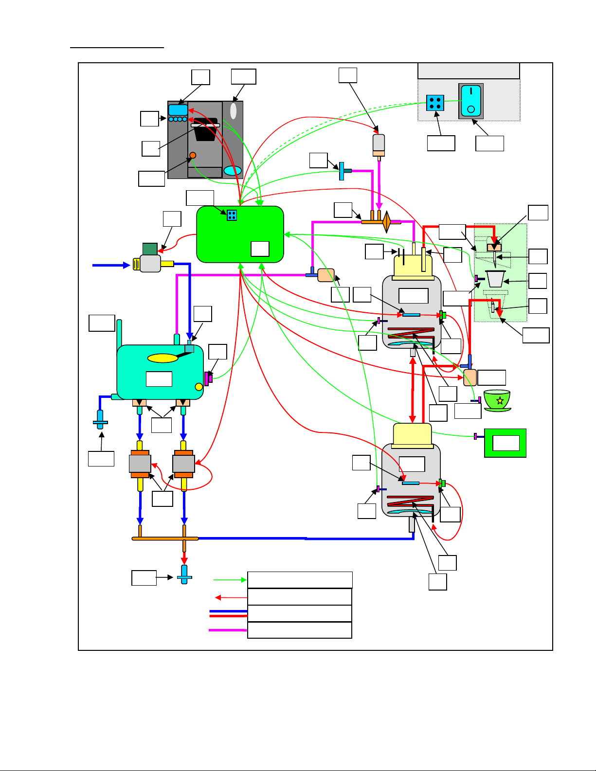
B3000 Brewer Water Flow Mechanisms
A schematic and legend showing the major components of the B3000 are provided (refer to page 8 and
9). The functions of these components are listed below.
1. Water filling – The B3000 is a direct plumbed machine. Municipal water is introduced to the unit
through the inlet valve [X]. The supply water is then led to the cold water tank [BB] via the rigid plastic
tube connected to the float valve [Y]. The cold water tank is allowed to fill approximately 16 ounces,
(480 milliliters) and then the valve [X] is de-energized (closed) by the CWT float magnet proximity
switch [Z] which controls the fill level. The proximity switch (located outside the tank) contains
magnetically activated reed switch which is controlled by a float magnet (located inside the tank) that
monitors the water level.
2. The Cold water Tank – The cold water tank [BB] functions primarily as housing for the secondary
overfill protection device which is the float valve [Y] and provides the air gap necessary for back flow
protection. If the normally closed inlet valve [X] were to fail open or otherwise be prevented from
closing due to debris or CWT float magnet / switch failure, then the float valve [Y] would shut off the
water supply once the water level rose to the level to activate the float lever. Back flow is prevented as
the float valve inlet is approximately 1 1/4 inches (29 mm) above the over flow port in the cold water
tank [BB]. The cold water tank also functions as the water supply reservoir for the brewing system.
The water supply in the tank is fed through two check valve [M] and tubing to the two cold water pumps
(CWP) [W] that supply water to the hot water tanks via the CWP elbow, CWP connectors, silicone
tubing, multi-connector tee, and silicone tube.
3. The Hot Water Tanks – The water flows through the bottom tank and into the top tank via a seal
assembly which includes two o-rings, a seal washer (between the o-rings), and the sealing cover. To
allow the hot water tanks to fill, the vent valve [J] is energized (opened) to allow air to leave the system
as the tanks are filled with water. Water delivered to the hot water tanks [TP] and [TB] is heated by the
heating elements located inside the tanks. The only one heater at a time is allowed to energize and the
heater in the top tank (brew tank) has priority. The water temperature is controlled by the thermistors
[V] located in each tank. To control volume stainless steel conductive probes are used to sense the brew
volumes of 4, 6, 8, and 10 ounces (120, 180, 240, and 300 milliliters). In order to brew the system is
closed, vent valve [J] de-energized (closed) to allow pressurization.
4. The Puncture Mechanism – the mechanism [DD] consists of the K-cup holding and puncturing
apparatus, a hot water delivery and brewed coffee path, and the hot water dispense valve [OO]. To brew
coffee one lifts the handle to present the K-cup holder [AA]. A K-cup is placed in the holder and the
handle is returned to the closed position. Upon closing the mechanism, the K-cup is punctured on the
top first by the entrance needle [N] and then the bottom by the exit needle [P]. The holes created in the
K-cup by the two needles are sealed about the needles by gaskets. Once the K-cup is in this ‘ready to
brew’ state and a cup is placed on the drip tray, brewing can commence. To brew, the system is closed,
vent valve [J] de-energized and the brew pump [G] is energized. The brew pump pressurizes the system
to approximately 4 psi (27.6 kPa). The air is delivered to the top of the brew tank via a silicone tube by
way of the filter tee [H]. The water in the brew tank is forced out of the tank through the integral brew
tube [L] in the upper hot water tank cover. The water flows out of the top cover through a silicone tube
to the entrance elbow which contains a check valve [M]. The water flows next trough the entrance
needle, contacts the coffee grounds in the K-cup, and brewed coffee is delivered through the exit needle
to the cup located on the drip tray.
B3000 SERVICE MANUAL
60-200807-000, REV C 6

5. Dispensing Hot Water - To deliver hot water only, the system is closed, vent valve [J] is deenergized, and the hot water dispense valve [OO] is opened. Through a combination of the force of
gravity and a pressure boost from the brew pump, water now flows from the lower hot water tank cover
thru a silicone tube, the hot water dispense valve [OO], a silicone o-ring, seal cover, and the hot water
trough. The water does not take the same path as in the coffee brewing process because the boost in
pressure form the brew pump [G] is lower than the cracking pressure of the brew path check valve [M].
B3000 SERVICE MANUAL
60-200807-000, REV C 7
U Brewer Schematic
g
g
JJ
Q
Rear Power Panel
HH
Inlet Water Supply
LL
PP
GG
X
System Control
Y
Z
DD
K
TB
V
S
CC
AA
OO
NN
KK
TP
V
System Inputs
System Outputs
Cold/Hot Water Plumbin
Air Plumbin
S
B3000 SERVICE MANUAL
60-200807-000, REV C 8

BREWER SCHEMATIC LEGEND
A Electronics, 3 PCBAs
TUThe Processor:UT
TUB3000 I/O OverviewUT
D Pressure Transducer
G Brew Pump
K 4 Brew Vol Conduct. Probes
N Entrance Needle
Q Auto reset TCOs (2)
TB, TP Hot Water Tanks. Brew, Preheat U Non-reset TCOs (2)
W Cold Water Pumps (2)
Z CWT Float Magnet / Switch
CC Power Switch and circuit breaker DD Puncture Mechanism Assy. EE Cold Water Tank Drain Valve
FF Hot Water Tank Drain Valve
JJ Optional Coin Changer
MM K-Cup® sensor
PP Coin changer interface
B LCD User Interface
E Puncture mech. Switch
C 4 Push buttons / LEDs
H Filter Tee
L Brew Tube
O K-Cup® Portion Pack
R Heating Elements (2)
J Vent Valve
M Check Valves (3)
P Exit Needle
S Baffles (2)
V Thermistors (2)
X Inlet Water Valve
Y Mechanical Float Valve
AA K-Cup® Holder Assembly BB Cold Water Tank
GG ICD2 programming Port HH Maintenance mode Push Button
KK Bin and bin sensor
NN Mug Sensor
LL CWT vent to bin
OO HW Dispense Valve
B3000 SERVICE MANUAL
60-200807-000, REV C 9
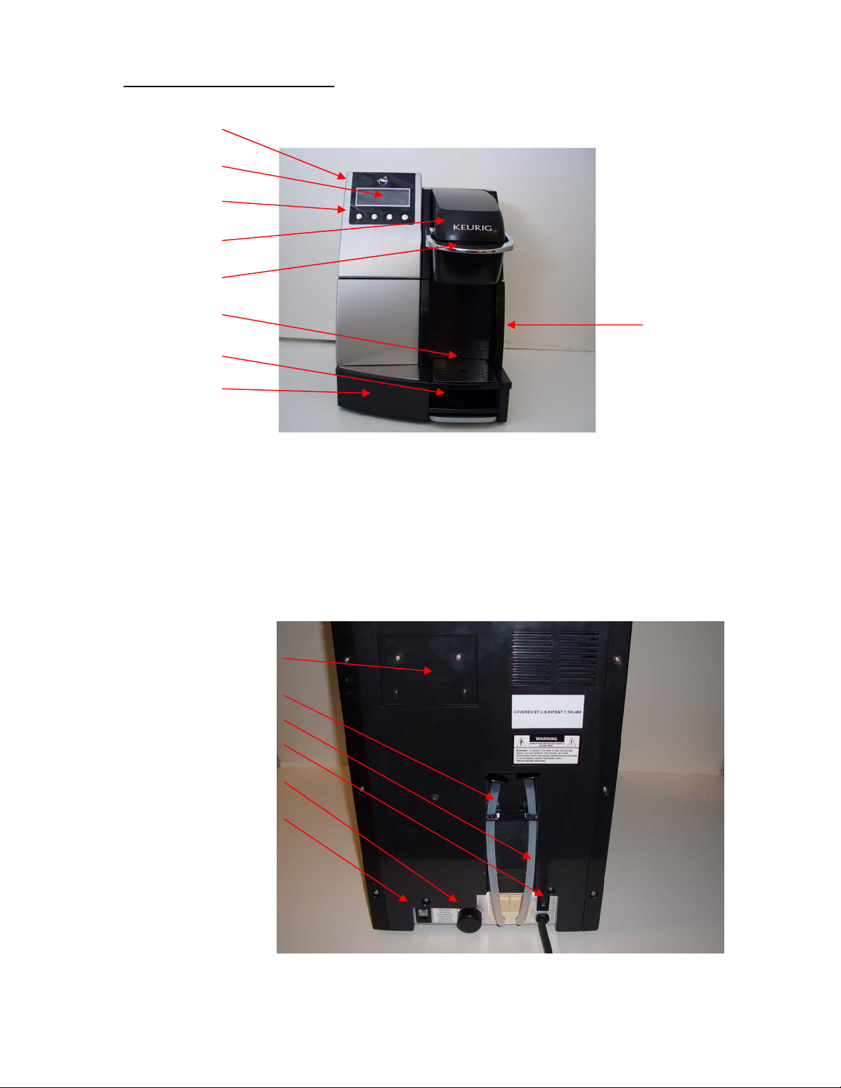
2. Brewer External Components
CONTROL PANEL
LCD DISPLAY – FIVE
LINES, BLUE
4 USER INTERFACE
BUTTONS
PUNCTURE
MECHANISM TOP
PUNCTURE HANDLE
UPPER DRIP PLATE –
CUP REST
LOWER DRIP PLATE –
TALL CUP REST
DRIP TRAY
COVER
Disposal
Bin Door
Handle
FILTER MOUNTING AREA
HOT WATER TANK DRAIN TUBE
COLD WATER TANK DRAIN TUBE
POWER SWITCH
INLET VALVE
RJ11 COIN CHANGER
CONNECTOR
B3000 SERVICE MANUAL
60-200807-000, REV C 10
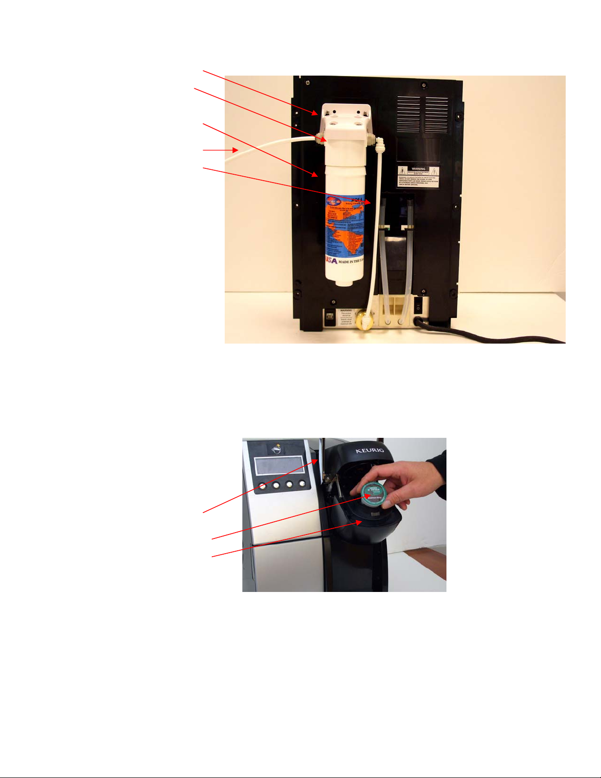
WATER FILTER BRACKET
WATER FILTER HEAD, KQ8A
WATER FILTER CARTRIDGE,
⅜” or ¼” DIAMETER TUBING
(FROM WATER SUPPLY)
(FROM FILTER TO INLET VALVE)
KQ8A
PUNCTURE HANDLE ROTATED BACK
WITH PUNCTURE MECHANISM IN OPEN
POSITION
K-CUP HOLDER
K-CUP
B3000 SERVICE MANUAL
60-200807-000, REV C 11
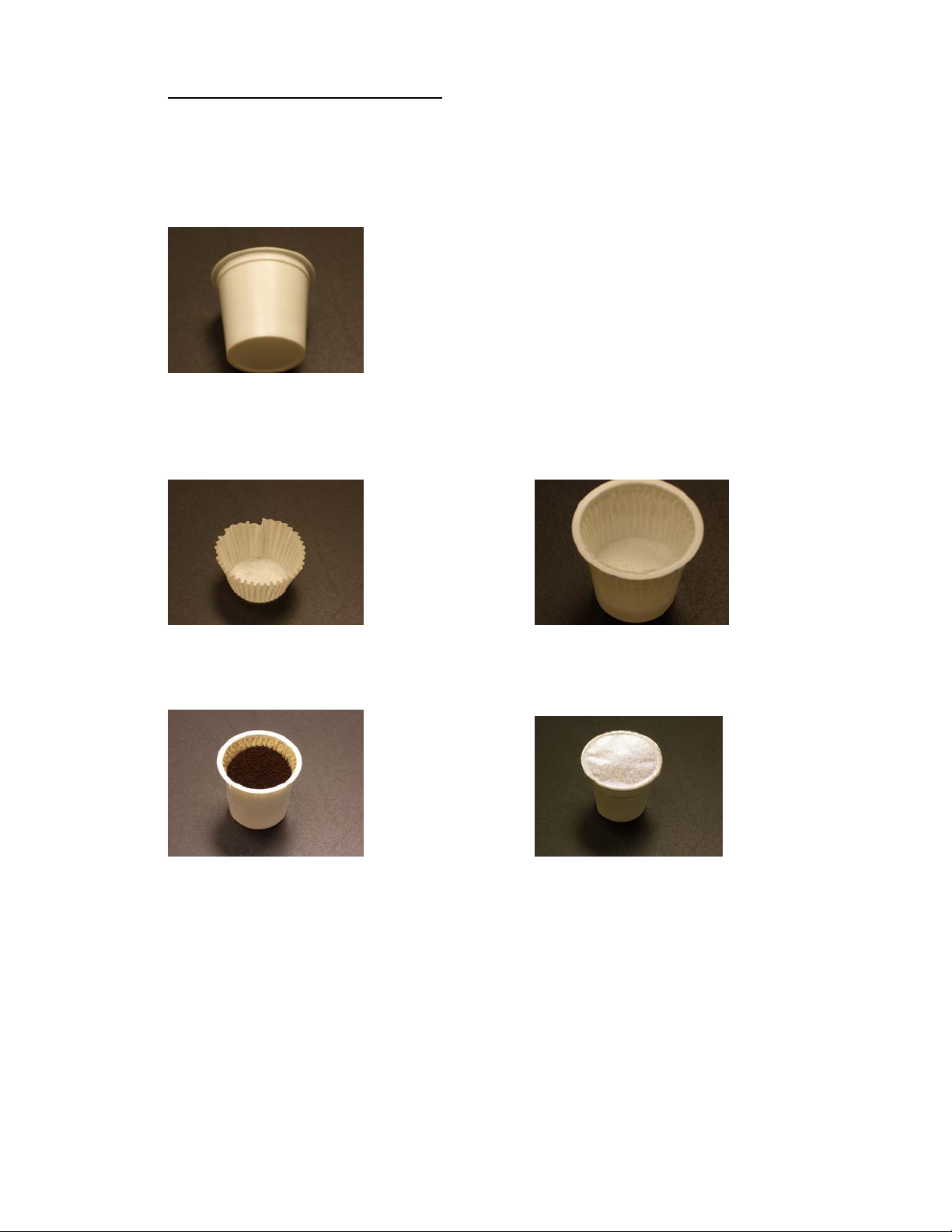
3. The Keurig K-Cup® Portion Pack
The Keurig B3000 Brewer may only be utilized in conjunction with the single serve portion pack
called the Keurig K-Cup. The K-Cup is fitted with a paper filter that is heat sealed to the inside
upper edge of the plastic cup.
Depending on the individual blend, up to approximately 9 to 14 grams of premium freshly
ground coffee is added. The K-Cup is nitrogen purged to remove oxygen and heat sealed with a
three ply foil lid to lock in freshness for at least 6 months.
During the brewing process water is introduced into the K-Cup under pressure via the entrance
needle, located in the Puncture Mechanism Module. The hot water extracts the coffee and passes
it through the filter paper. The exit needle, located on the outer edge of the K-Cup holder, allows
the brewed coffee to be dispensed into a cup or mug.
B3000 SERVICE MANUAL
60-200807-000, REV C 12

4. Appliance Safety
When using electrical appliances, basic safety precautions must always be followed. Read all
instructions before using this brewer. Failure to comply with the instructions risks equipment
damage, fire or severe bodily injury.
WARNING: ALWAYS UNPLUG THE BREWER BEFORE SERVICING
• To reduce the risk of fire or electric shock, do not expose this brewer to rain or moisture.
• Do not immerse the brewer in water, as this could lead to electric shock, electrical and or
mechanical malfunctions.
• Do not use brewer for other than its intended use.
• Both the Cold Water Tank (CWT) and the Hot Water Tank (HWT) should be drained
prior to moving the B3000 from one location to another.
POWER SUPPLY
Only use a correctly wired and grounded 120VAC / 60Hz socket outlet rated for at least 15A
service. It is recommended that a Ground Fault Circuit Interrupter (GFCI) outlet be used.
• Avoid sharing the same outlet with other appliances.
• Your brewer is equipped with a molded, grounded three prong polarized AC line plug.
This is a safety feature. Do not defeat the safety purpose of the polarized plug.
• The system requires a 3-wire grounded outlet with a minimum of 15 amp service.
• Do not use extension cords with this brewer.
5. Brewer Setup
Unpacking Instructions
WARNING: Keep all plastic bags away from children.
1. Place Brewer box on its side on a large steady surface such as a table, countertop, or on the
floor. Open the box from the end that says UP.
2. Remove the Quick Start Guide, Use & Care Guide and other literature.
3. Reach into the box and grasp the poly foam packing that protects the Brewer.
4. Carefully pull the poly foam toward you and out of the box. Remove the poly foam
packaging material surroundings the brewer.
5. Place the brewer upright on a flat, steady surface.
6. Remove the plastic bag.
7. It is recommended that you save all packing materials and shipping carton in the event that
the brewer must be shipped or stored.
B3000 SERVICE MANUAL
60-200807-000, REV C 13

Filter Requirements
The Keurig B3000 brewer system requires the use of a water filtration system to optimize the
coffee flavor and brewer reliability. Two mounting holes with screws have been provided on the
back of the brewer for this purpose.
Keurig recommends the Omnipure KQ8A filter. A filter kit (part number 5025) is available from
Keurig. This kit contains a KQ8A filter, filter head, and mounting bracket.
NOTE: NO PLUMBING CONNECTORS ARE PROVIDED WITH THIS KIT.
All KQ8A filter cartridges must have a minimum of four gallons of water run through it
after mounting to the brewer and before they are connected to the brewer’s Inlet Valve at
the install location. This procedure will prevent fine particles of carbon from entering and
clogging the water inlet valve.
Getting Started
You will need several tools for the installation or servicing the B3000 brewing system. They are
as follows:
• Two Number 2 Phillips screw drivers (8” and 12”)
• Pliers (Regular Adjustable and Needle Nose)
• Wire Cutters
• 6 mm Nut Driver
Next:
a) Attach a ¾” female garden hose connection that will reduce to either a ⅜” or ¼” connection
to the Inlet Valve.
b) Mount the filter assembly to the brewer using the screws provided on the back of the brewer.
c) Flush the filter BEFORE connecting to the Inlet Valve.
d) Plug brewer into a dedicated GFCI outlet. If the electric circuit is overloaded with other
appliances, the circuit breaker may trip. If possible, the brewer should be operating on its
own circuit, separate from other appliances. Never use an extension cord.
B3000 SERVICE MANUAL
60-200807-000, REV C 14

6. User Interface & Brewing Procedure
IMPORTANT: The brewer must be primed for its first use as set forth below. If Spanish or
French are going to be the primary language, then you must go to the MENU MODE (page 19)
and change the language before proceeding with the priming of the brewer. The brewer’s default
language is English.
(Without a coin changer)
NOTE: The B3000 power switch uses “0” for OFF and “
-” for ON.
Priming the Brewer
1. Place a cup or mug (8 oz Min) on the Drip Tray Plate (if not done, the brewer will prompt for the
cup or mug later in the priming sequence)
2. Press power switch to the “
-” position.
3. At power up, the brewer will display the following:
KEURIG B3000 BREWING SYSTEM
4. The display will automatically change to:
CONNECT WATER AND THEN PRESS FLASHING BUTTON
5. After water is connected, then press button.
6. The display will read:
PRIMING
7. Then automatically change to:
PRIMING
HEATING - PLEASE WAIT
8. After heating has taken place the display will read:
PLACE YOUR CUP
OR SELECT ‘ CONT ‘
9. After placing the cup the screen will read:
PRESS FLASHING BUTTON
TO CONTINUE
10. Press the flashing button and conduct a water only brew.
11. After the water only brew is complete the unit is primed and the following will be displayed:
PRIME COMPLETE
12. Next you will read:
HEATING – PLEASE WAIT
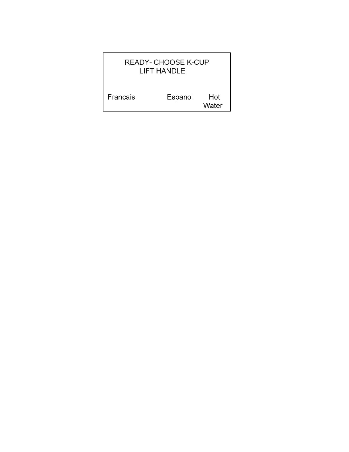
13. After heating has taken place the screen will show: (With a Coin Changer)
READY – CHOOSE K-CUP READY
LIFT HANDLE DEPOSIT XXX CENT
B3000 SERVICE MANUAL
60-200807-000, REV C 15
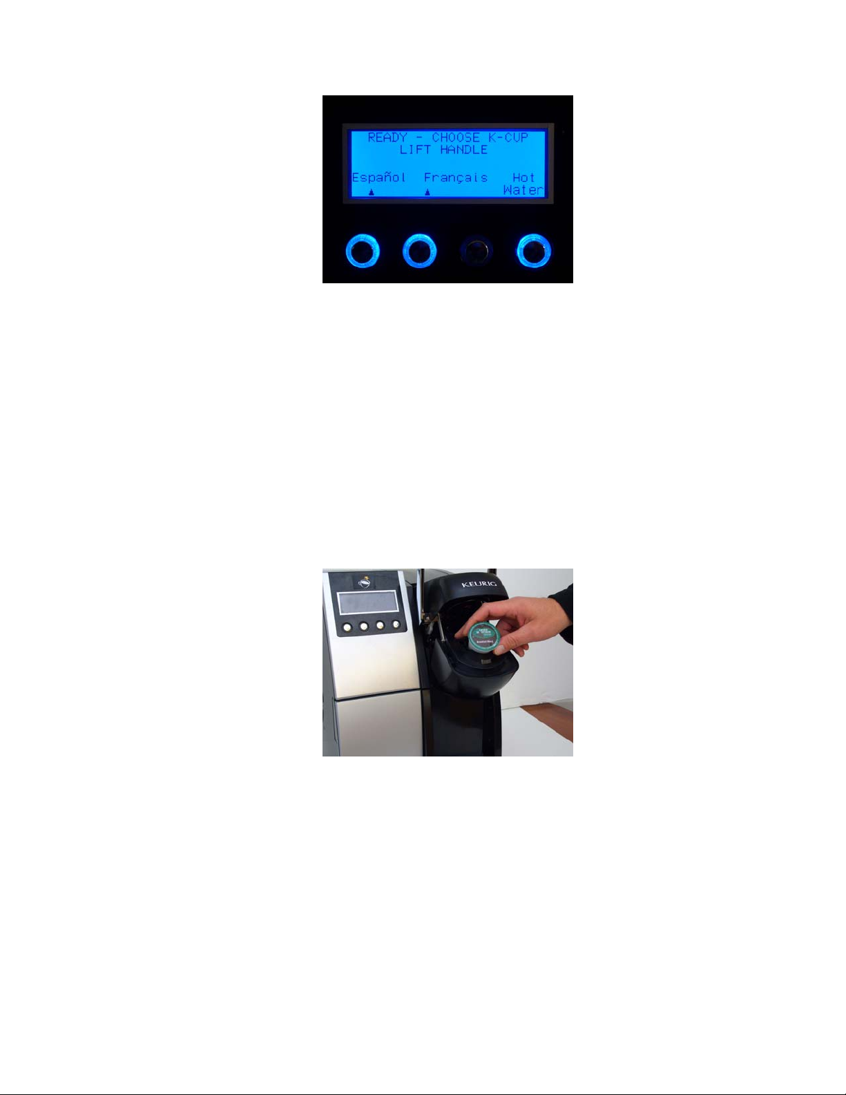
Ready to Brew your First Cup (Without Coin Changer)
1. When the LCD displays the above information, the brewer is ready for use.
2. Select a K-Cup portion pack.
NOTE: Do not remove the foil lid or puncture the K-Cup portion pack.
3. Lift the puncture mechanism handle. The K-Cup holder will open towards you.
CAUTION: There are two sharp needles that puncture the K-Cup portion pack, one in the
puncturing mechanism and the other in the bottom of the K-Cup holder. To avoid risk of injury,
do not put your fingers in the K-Cup chamber.
4. Place a K-Cup in the K-Cup holder.
5. Lower the handle completely to close the puncture mechanism
B3000 SERVICE MANUAL
60-200807-000, REV C 16

6. Place a cup or mug on the Cup/Drip Tray plate.
7. The LCD screen will display the image below. A choice of 4, 6, 8, and 10 oz cup sizes are
available. Make cup size selection at this time.
8. After the selection is made, the image below will display which cup size is brewing by having
the respective button corresponding to the volume size being illuminated.
CAUTION: There is extremely hot water in the K-Cup holder during the brew process. To avoid
risk of injury, do not lift the handle or open the K-Cup holder during the brewing process.
B3000 SERVICE MANUAL
60-200807-000, REV C 17
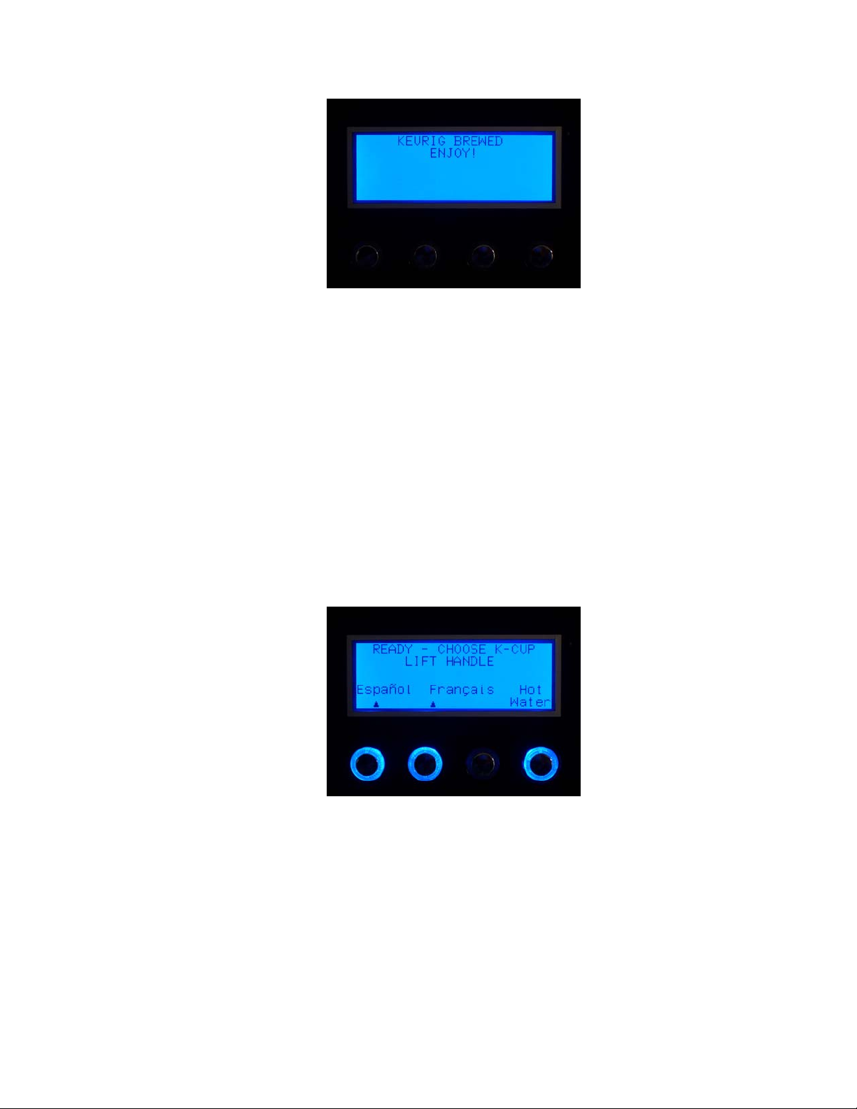
9. At the end of the brewing process the image below will be displayed for 4 seconds.
10. There may be a short pause (approximately 20 seconds) before the next brewing process can
begin. The entire brew process lasts for approximately 40 to 52 seconds (depending upon brew
size selected) and ends with a burst of air to remove all liquid coffee or tea from the K-Cup.
11. Enjoy your first cup of Keurig Brewed gourmet coffee or tea!
NOTE: Following the brew, your brewer will fill in preparation for the next brew. The pump will make
a vibrating sound. This is normal.
Dispensing Hot Water
The B3000 brewer is capable of dispensing hot water for making hot chocolate, instant soups etc. The
path of the water delivery is separate from the coffee delivery path.
One of the button options is ‘Hot Water’. Hot water will be dispensed as long as the button is pressed
and held delivering a total of 8 oz max before refilling. If the button is not lit, wait for heating to
complete.
B3000 SERVICE MANUAL
60-200807-000, REV C 18
7. Menu Mode (For brewers with serial numbers 1 thru 7505)
The Menu Mode allows you to:
• Set the language to be displayed.
• See the number of brew cycles that the brewer has completed.
• Prime after draining.
• Set the brewer to vend / no vend.
• Set pricing.
• Adjust the brew temperature between 192 and 187 degrees F (89 and 86 degrees C).
• Invert the background text color display intensity.
• List your telephone service number. (Scroll and set all ten digits, using the NEXT and ADJUST
buttons).
• List the LAST brewer error code.
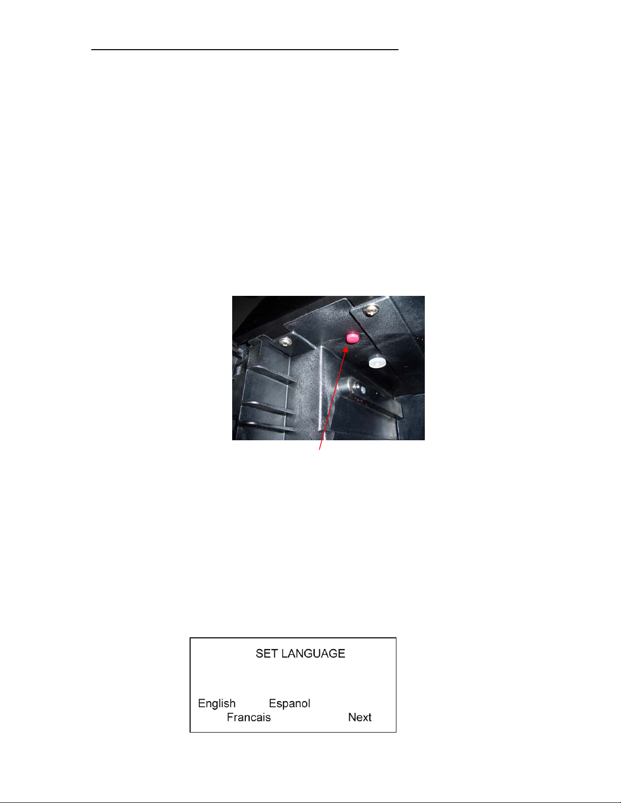
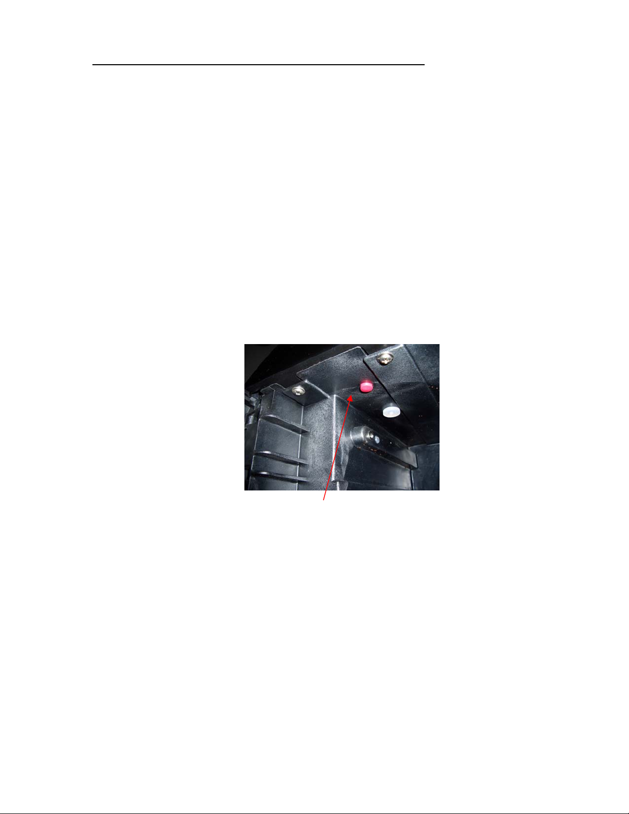
To enter the MENU MODE
1. Press the power button, located on the rear of the brewer, to the “0” position.
2. Open the K-Cup bin door and locate the RED button at the top of the bin area.
3. Press the power button, located on the rear of the brewer, to the “
push this RED button four times.
The first screen displayed will be where you change the default language to either Spanish or French, if
English is not going to be the primary language displayed.
NOTE: If this screen does not appear, then repeat steps 1 and 3 again until it does.
Scroll thru the menu screens answering the prompts that appear.
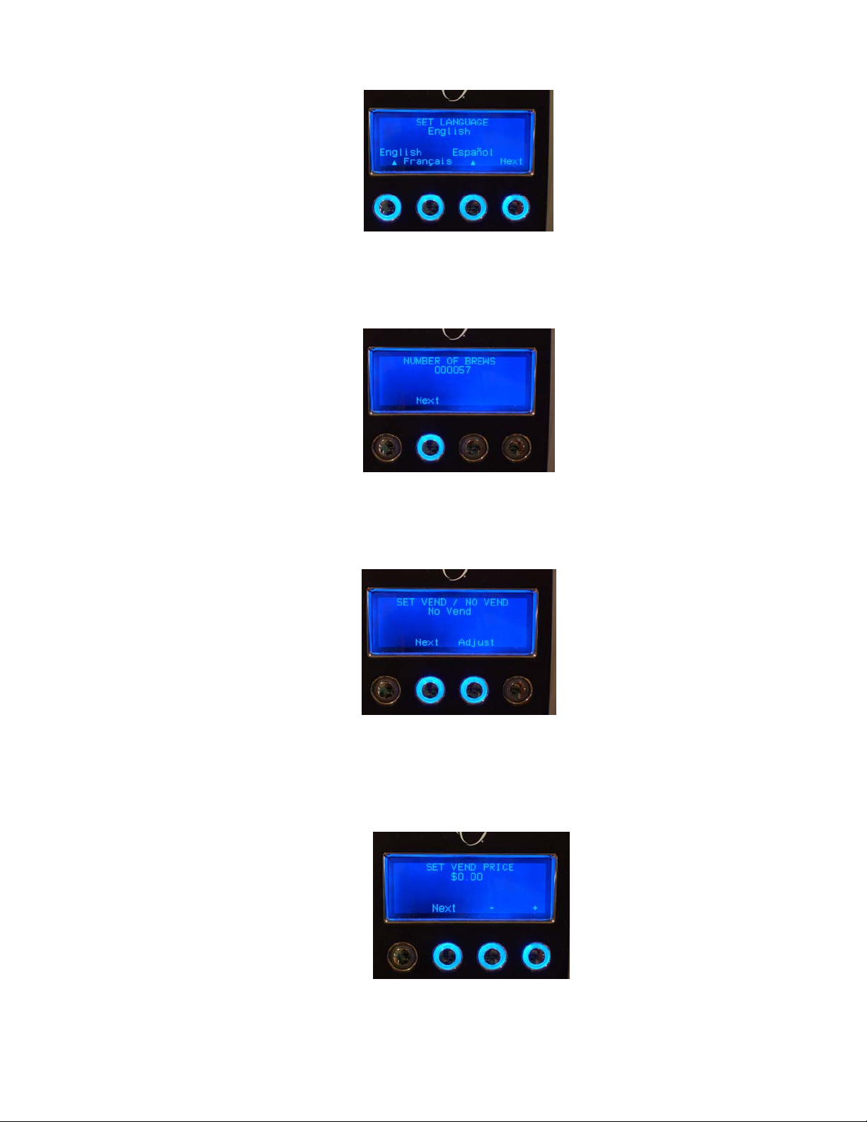
1. Once the menu is accessed the display will look like this (set language):
B3000 SERVICE MANUAL
60-200807-000, REV C 19
-” position. Within 2 seconds,
2. Press the ‘Next’ button.
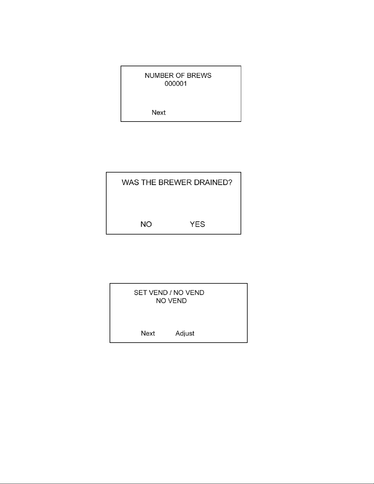
3. The display will look like this (number of brews):
4. Press the ‘Next’ button.
5. The display will look like this (was brewer drained):
6. Press the ‘Yes’ or ‘No’ button as appropriate.
7. The display will look like this (set vend / no vend):
8. If a coin unit is being used, Press ‘Adjust’ button to ‘Vend at Set the price’ (image on left
below). Then press next button
B3000 SERVICE MANUAL
60-200807-000, REV C 20
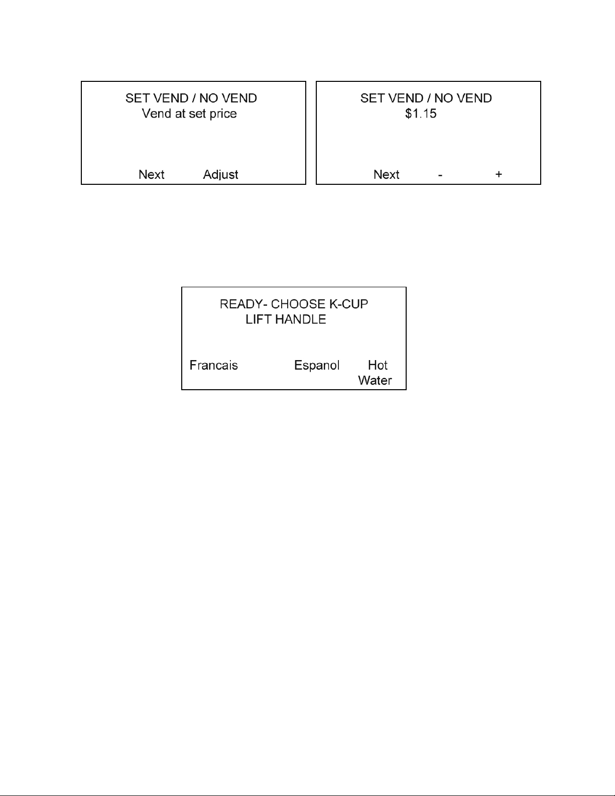
9. The display will look like the image on the right below. Adjust price by pressing the + or –
button to get desired price. Adjustments are in $0.05 increments.
10. Press the ‘Next’ button after selection is made.
11. The next display will read ‘Set the Brew Temp’ at the display continue to press the next button
until the following display is seen, and then the brewer and coin changer unit are ready for
operation.
NOTE: YOU MUST SCROLL THROUGH THE MENU MODE COMPLETELY. FAILURE TO
DO SO WILL NOT SAVE ANY CHANGES THAT HAVE BEEN MADE.
B3000 SERVICE MANUAL
60-200807-000, REV C 21
8. Menu Mode (For brewers with serial numbers 7506 and above)
The Menu Mode allows you to:
• Set the language to be displayed.
• See the number of brew cycles that the brewer has completed.
• Set the brewer to vend / no vend.
• Set pricing.
• Adjust the brew temperature between 192 and 187°F (89 and 86 degrees C).
• Invert the background text color display intensity.
• List your telephone service number. (Scroll and set all ten digits, using the NEXT and ADJUST
buttons).
• Turn ON / OFF Mug Light.
• Turn ON / OFF the Hot Water Valve.
• Set available Cup Sizes.
• List the LAST brewer error code.
To enter the MENU MODE
1. Press the power button, located on the rear of the brewer, to the “0” position.
2. Open the K-Cup bin door and locate the RED button at the top of the bin area.
3. Press the power button, located on the rear of the brewer, to the “-” position. Within 4 seconds,
push this RED button four times.
The first screen displayed will be where you change the default language to either Spanish or
French, if English is not going to be the primary language displayed.
NOTE: If this screen does not appear, then repeat steps 1 and 3 again until it does.
Scroll thru the menu screens answering the prompts that appear.
B3000 SERVICE MANUAL
60-200807-000, REV C 22
1. Once the menu is accessed the display will look like this (set language):
2. Press the ‘Next’ button.
3. The display will look like this (number of brews):
4. Press the ‘Next’ button.
5. The display will look like this (set vend / no vend):
6. If a coin unit is being used, Press ‘Adjust’ button to ‘Vend at Set the price’. Then press next
button.
7. The display will look like these (set vend price):
B3000 SERVICE MANUAL
60-200807-000, REV C 23
8. Adjust price by pressing the + or – button to get desired price. Adjustments are in $0.05
increments.
9. Press the ‘Next’ button after desired amount has been set.
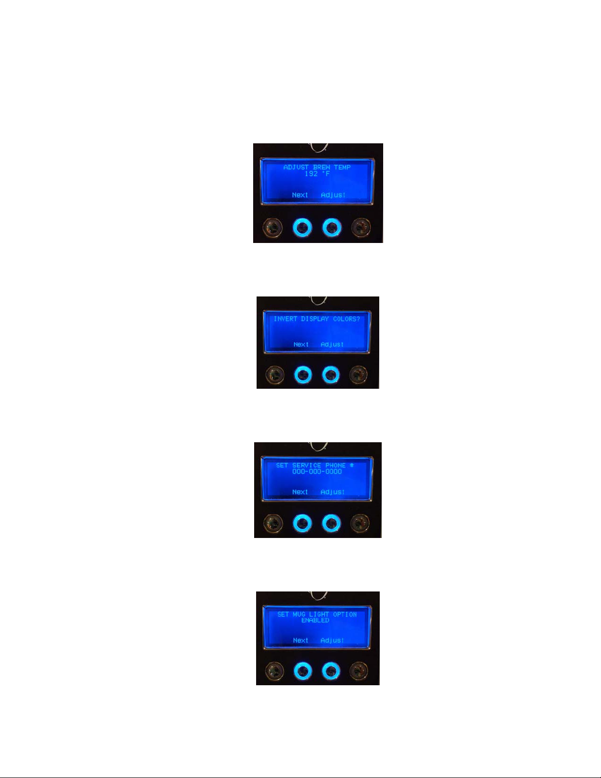
10. The next display will look like these (set the brew temp). The temperature can be adjusted in
one degree increments between 187 – 192 °F by pressing the “Adjust” button.
11. The next screen will look like these (invert display colors). You can changes the display to
LIGHT back ground with DARK letters by pressing the “Adjust” button.
12. The next screen will look like this (set service phone #). Enter your phone number here. You
must scroll through all ten digits.
13. The next screen will look like this (set mug light). You can disable the mug placement sensor by
pressing the “Adjust” button
B3000 SERVICE MANUAL
60-200807-000, REV C 24
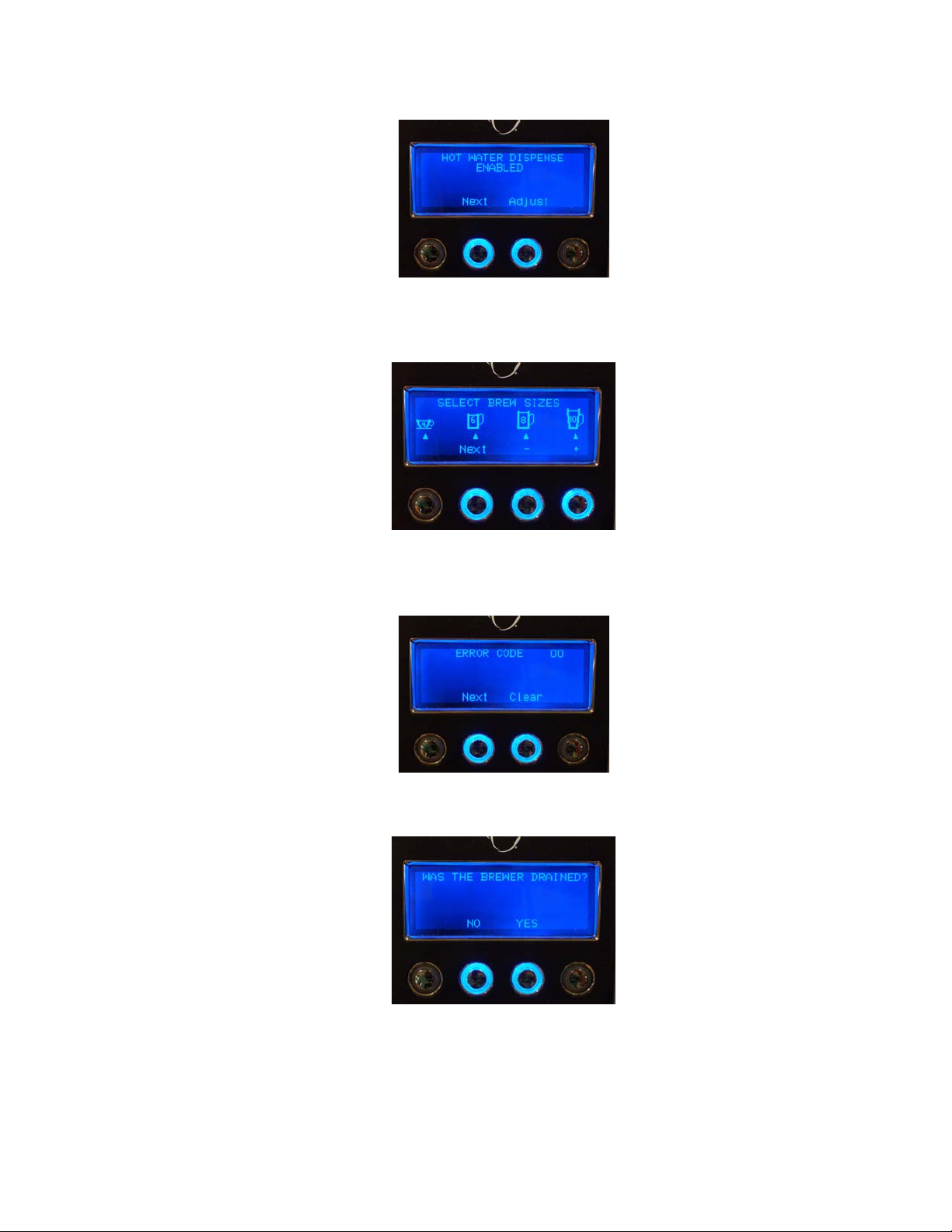
14. The next screen will look like this (hot water dispense). You can disable the plain Hot Water
button by pressing the “Adjust” button.
15. The next screen will look like this (select cup sizes). You can select which cup sizes you want
the brewer to dispense. You can disable up to 3 cup sizes. One cup size has to be on.
16. The next screen will look like this (error code). The last error condition that the brewer detected
will be display in this menu. See the ERROR CODE chart on page 41 for code definitions
17. The next screen will look like this (was brewer drained). Press “NO” or “YES” accordingly.
This is the last MENU for the Menu Mode.
NOTE: YOU MUST SCROLL THROUGH THE MENU MODE COMPLETELY. FAILURE TO
DO SO WILL NOT SAVE ANY CHANGES THAT HAVE BEEN MADE.
B3000 SERVICE MANUAL
60-200807-000, REV C 25

9. Draining the Brewer
When you wish to drain the brewer, the following steps must be followed:
1. Press the power button to the “0” position and unplug power cord.
2. Shut off water and disconnect water supply to the brewer. Turn the brewer around so the back is
facing you.
3. Move the brewer close to the edge of a sink or large bucket so that the drain hoses hang over
either the sink edge or into the bucket
4. Remove both the Hot Water and Cold Water hoses from their clips. Remove drain plugs from
each hose.
CAUTION: THE WATER WILL BE VERY HOT!
5. When the flow of water stops, the brewer’s internal hot water tank and cold water tank will be
empty.
NOTE: The brewer is drained by gravity. It will take approximately 3 minutes to
complete. There will always be a small amount of water left in the drain hoses.
B3000 SERVICE MANUAL
60-200807-000, REV C 26
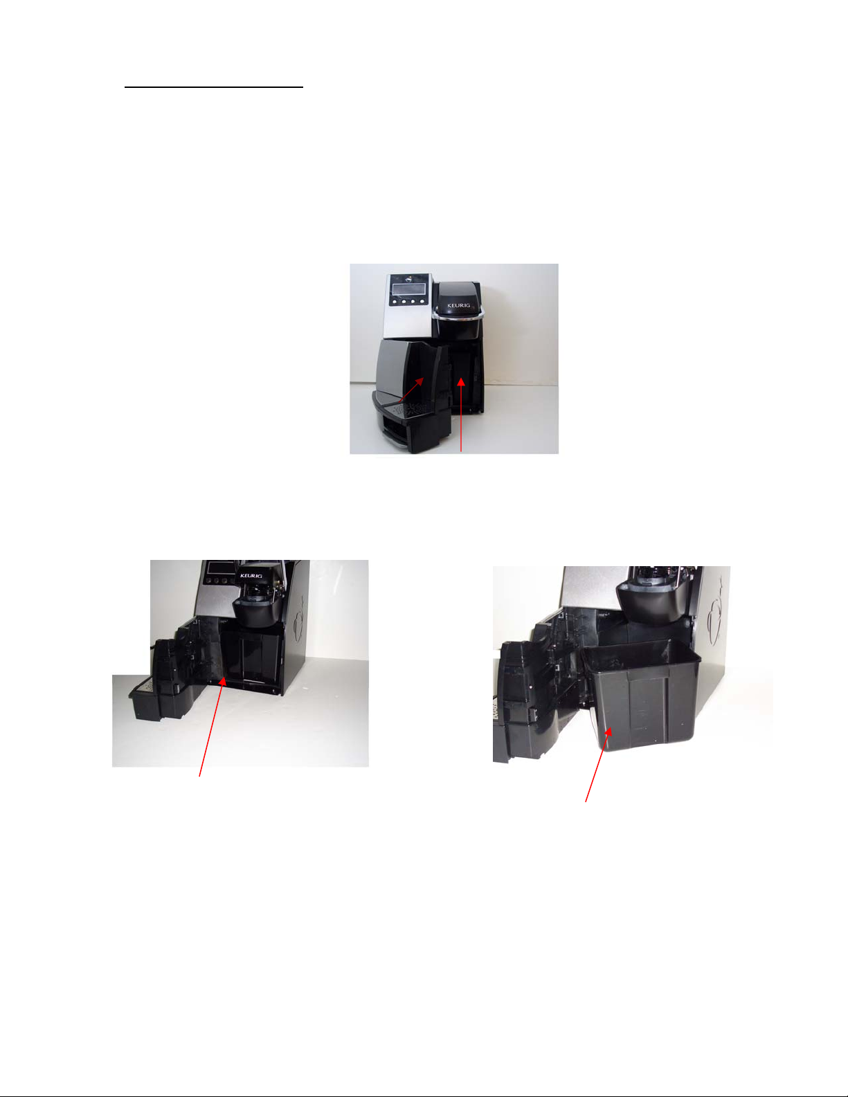
10. Emptying the K-Cup Bin
The used K-Cups are automatically ejected into the internal K-Cup bin. When the K-Cup bin requires
emptying, the brewer will display:
EMPTY K-CUP BIN
To empty the K-Cup bin, open the brewer door by grasping the door handle and swinging door fully
open to remove bin from brewer. Dispose of the used K-Cups and reinstall the bin. The bin will ONLY
go back inside the brewer one way.
Door
Handle
DOOR FULLY OPEN WITH K-CUP
BIN VISIBLE
BREWER DOOR IS HINGED,
ALLOWING ACCESS TO K-CUP
BIN
K-CUP BIN REMOVED FROM
BREWER
B3000 SERVICE MANUAL
60-200807-000, REV C 27
II. Construction
1. The Modules
What follows are images of the individual modules to show their general configuration. Not all of the
parts in the module are listed.
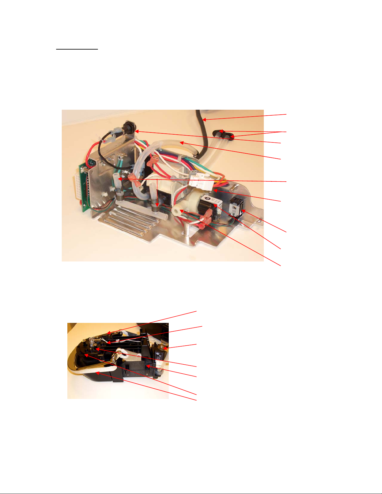
A. Power – located at lower rear of brewer:
POWER CORD
DRAIN TUBES
FUSE HOLDER
COLD WATER TANK
DRAIN TUBE
WATER PUMP
MANIFOLD
HOT WATER TANK
HARNESS
COIN
CHANGER
CONNECTION
INLET VALVE
TUBE CONNECTOR
(CWT)
B. Puncture Mechanism – located at the upper right front of brewer:
PIVOT PLATE
SENSOR HARNESS ASSEMBLY
MICRO SWITCH
HOT WATER DISPENSE VALVE
PRESSURE PLATE
FRAME PUNCTURE MECHANISIM
ENTRANCE NEEDLE ASSEMBLY
HANDLE
B3000 SERVICE MANUAL
60-200807-000, REV C 28

C. Hot Water Tank – located at the left rear of brewer:
BREW TANK COVER
HWT MOUNTING BACK
CONNECTORS
HWT MOUNTING FRONT
D. Cold Water Tank – located at the upper right rear of brewer:
FILTER TEE
VENT TUBE
AIR PUMP
VENT VALVE
MAGNET
B3000 SERVICE MANUAL
60-200807-000, REV C 29

E. Cold Water Pump – located at the lower right rear of brewer:
R
F. Control Panel – located on the front of brewer:
COLD WATER PUMPS
PLATE
VIBRATION ISOLATORS
LCD / PCB COVER
LCD DISPLAY
CONTROL
BUTTONS
PRESSURE
TRANSDUCER
TUBE /
CONNECTO
B3000 SERVICE MANUAL
60-200807-000, REV C 30

G. FRONT DOOR – located on the front of brewer:
CUP PLACEMENT LED
SENSORS
CUP/DRIP TRAY
LOCATION
DOOR HANDLE
H. BIN FULL SENSOR - located on the left/right side of brewer:
BIN FULL SENSORS
I. DRIP TRAY– located on the front of brewer:
TRIM INSERT
DRIP TRAY
DRIP PLATE LOWER
DRIP PLATE UPPER
AND BASE
B3000 SERVICE MANUAL
60-200807-000, REV C 31

J. MAIN PCB – located on the left side looking at the front of brewer:
HOT WATER VALVE
CONNECTOR
MAIN POWER
HARNESS
CONNECTOR
MAIN HARNESS
CONNECTOR
SOFTWARE VERSION
NUMBER
B3000 SERVICE MANUAL
60-200807-000, REV C 32

2. REPLACEMENT PART NUMBERS
POWER MODULE 16-200904-000
K-CUP PUNCTURE MODULE 16-200905-000
HOT WATER TANK MODULE 16-200906-000
COLD WATER TANK MODULE 16-200907-000
COLD WATER PUMP MODULE 16-200908-000
CONTROL PANEL MODULE 16-200914-000
FRONT DOOR MODULE 16-200909-000
MAIN HARNESS MODULE 16-200910-000
BIN SENSOR MODULE (Included in Main Harness Module) USE 16-200910-000
DRIP TRAY MODULE 16-200912-000
MAIN PCB MODULE 16-200913-000
HOT WATER DISPENSE VALVE ASSEMBLY 16-200894-000
K-CUP HOLDER ASSEMBLY 16-200936-000
INLET VALVE FILTER 01-201200-000
LOCKSET COIN MECH B3000 16-200962-000
CHUTE B3000 16-200951-000
INLET WATER VALVE B3000 16-200959-000
DISPOSAL BIN 16-200969-000
BASE PLATE MODULE 16-200938-000
CLAMP, HOSE, 14.81MM ID x 7.92MMW, SPRING STL 04-200819-000
CLAMP, HOSE, 9.53MM ID X 7.92MM W, SPRING STL 04-200685-000
CLAMP, HOSE, 12.45MM ID X 7.94MM W, SPRING STL 04-200872-000
CLAMP, HOSE, 13.21MM ID X 7.92MM W, SPRING STL 04-200684-000
CLAMP, HOSE, 8.51 MM ID X 7.92 MM W, SPRING STL 04-200880-000
CLAMP, HOSE, 6.1MM ID X 6.35 MM W, SPRING STL 04-200873-000
ENTRANCE NEEDLE ASSEMBLY (ENA) 16-200993-000
K-CUP HOLDER PIVOT 16-200995-000
ENTRANCE NEEDLE GASKET, SN ABOVE 7506 16-200997-000
B3000 SERVICE MANUAL
60-200807-000, REV C 33

III. Servicing
1. Preventive Maintenance
Regular cleaning of the Brewer’s external components is recommended.
CAUTION: Never immerse the base unit in water or other liquids.
The brewer’s enclosure and other external components may be cleaned with a non-toxic food grade
cleaner and a damp, non-abrasive cloth.
• The Drip Tray and Drip Tray Plate should be periodically inspected and rinsed clean.
• The K-Cup Bin should be cleaned on a regular basis.
• The K-Cup holder/funnel should be periodically removed from the Puncture Mechanism and
cleaned with warm water.
CAUTION:
K-CUP PORTION PACK. USE EXTREME CARE IN CLEANING THIS AREA.
1. The KQ8A water filter should be replaced every 6 months.
2. Troubleshooting
The B3000 has an Alpha/Numeric LCD display informing you what is wrong with the brewer, if it
should develop an error. All repairs of the brewing system are done on a modular level.
By looking at the error code being displayed and reading the diagnostic chart provided in this manual, or
hitting the Menu Button (page 19 for brewers up to serial number 7505, page 22 for brewers with serial
number 7506 and up) once, you will be able to determine which module needs to be replaced.
To enter the MENU MODE refer to page 19 for brewers up to serial number 7505. Page 22 for brewers
with serial number 7506 and up.
THERE IS A SHARP NEEDLE THAT PUNCTURES THE BOTTOM OF THE
B3000 SERVICE MANUAL
60-200807-000, REV C 34

3. Diagnostics – Error Codes:
The B3000 contains real-time error detection. There are a number of operational errors that, if
encountered, will disable the brewer, produce an error code onto the LCD display, and will also flash all
4 buttons on the front panel LED’s to attract attention. The power may be cycled to attempt to clear the
error, but if it occurs again, the same message will be displayed.
Below is a summary of all errors, their meanings and the menu messages.
ERROR CODES MESSAGE DISPLAY PROBABLE CAUSE
01
02
03
04
05
06
07
08
09
10
ERROR – TCO HIGH OPEN
CALL FOR SERVICE
000-000-0000
ERROR – TCO LOW OPEN
CALL FOR SERVICE
000-000-0000
ERROR – DESCALE NOW
CALL FOR SERVICE
000-000-0000
ERROR – CHECK WATER SUPPLY
CALL FOR SERVICE
000-000-0000
ERROR – RUNAWAY FILL
CALL FOR SERVICE
000-000-0000
ERROR – LOW TANK FROZEN
CALL FOR SERVICE
000-000-0000
ERROR – HIGH TANK FROZEN
CALL FOR SERVICE
000-000-0000
ERROR – LOW TANK HI TEMP
CALL FOR SERVICE
000-000-0000
ERROR – HIGH TANK HI TEMP
CALL FOR SERVICE
000-000-0000
ERROR – COIN JAM
CALL FOR SERVICE
000-000-0000
MODULES: POWER, HWT
MODULES: POWER, HWT
DESCALE REQUIRED
MODULES: CWT, POWER
MODULES: CWT, POWER
PREHEAT TANK COLD
MODULES: HWT
BREW TANK COLD
MODULES: HWT
MODULES: POWER, HWT
MODULES: POWER, HWT
MODULES: COIN MECH
B3000 SERVICE MANUAL
60-200807-000, REV C 35

4. Removing/Installing Modules
The B3000 brewing system is modular in design. This design facilitates ease of repair at customer
locations. There are no component level repair capabilities for this brewer.
The following describes the removal of each of the modules.
NOTE: BOTH THE HOT AND COLD WATER TANKS MUST BE DRAINED
AND THE UNIT UN-PLUGGED BEFORE ANY MODULE IS REMOVED.
A. REMOVAL of BACK and SIDE PANELS
For Right side panel removal, locate the three screws on the left side of the back panel loosen the screws
and pull side panel back for removal.
For Left side panel removal, locate the three screws on the right side of the back panel loosen the screws
and pull side panel back for removal.
For Back Panel removal when both side panels are removed loosen the four screws on the back panel
and remove.
Right side
NOTE: All screws are captive they cannot be removed from panels
Left side
B3000 SERVICE MANUAL
60-200807-000, REV C 36

B. POWER MODULE (Located in the back on the bottom edge of the brewer)
See REMOVAL of OUTER PANELS (page 36). After completion of panel removal, the technician
must attach an ESD wrist strap to themselves and the metal base plate of the brewer.
Spare Fuse Location
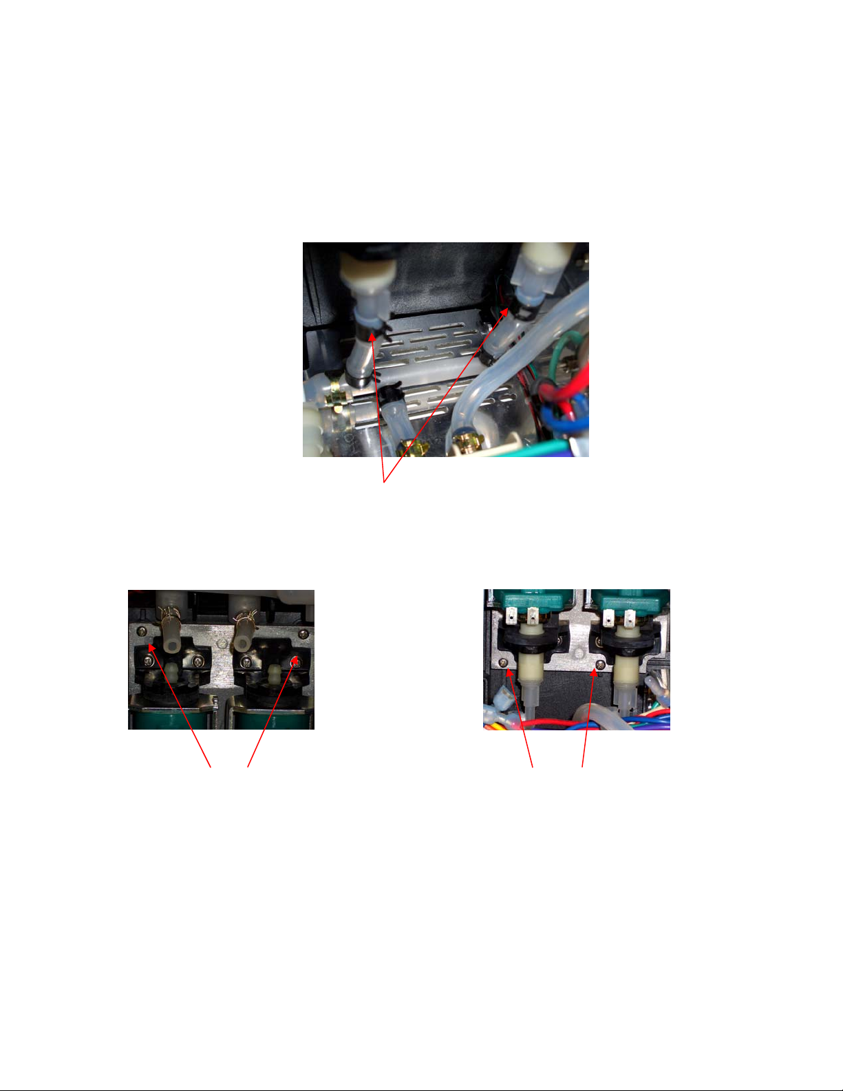
1. Completely loosen the two captive screws holding the Power Module to the bottom base plate
and pull out slightly. This will help in accessing the hoses on the pumps.
2. Prior to disconnecting the four wire connections attached to bottom of the green water pumps
make a note of their respective connections. Disconnect these four wires.
NOTE: The wires must be reconnected to their proper connections when installing the new
module. Failure to do so will result in having extremely noisy pumps while they are in operation.
B3000 SERVICE MANUAL
60-200807-000, REV C 37

3. Disconnect the clamps and water hoses attached to the water manifold.
4. Disconnect the Multi Connector Tee manifold from the old Power Module and add to the
replacement unit.
5. Disconnect the Cold Water drain tube from the bottom of the tank.
B3000 SERVICE MANUAL
60-200807-000, REV C 38

6. Disconnect the tube from the Inlet Valve that goes to the Cold Water Tank. The Inlet Valve is
located on the Power Module. This is a quick release tube connection. Remove the black locking
clip from the fitting if present. Push in on the collar, and pull out the tube.
7. Disconnect the wire harness attached to the Hot Water Tank module.
Looking at the left side of the brewer when facing from the front, locate the main power harness, and
transformer.
8. Disconnect the two transformer and main power harness from the Power Module PCB.
9. The Power Module can now be removed from the brewer.
B3000 SERVICE MANUAL
60-200807-000, REV C 39
10. Install the new module and connect all of the appropriate connections, hoses, and wires making
sure that they are secure and tight.
11. Conduct a BIT test (see appendix VII on page 85) to insure the proper function of the brewer.
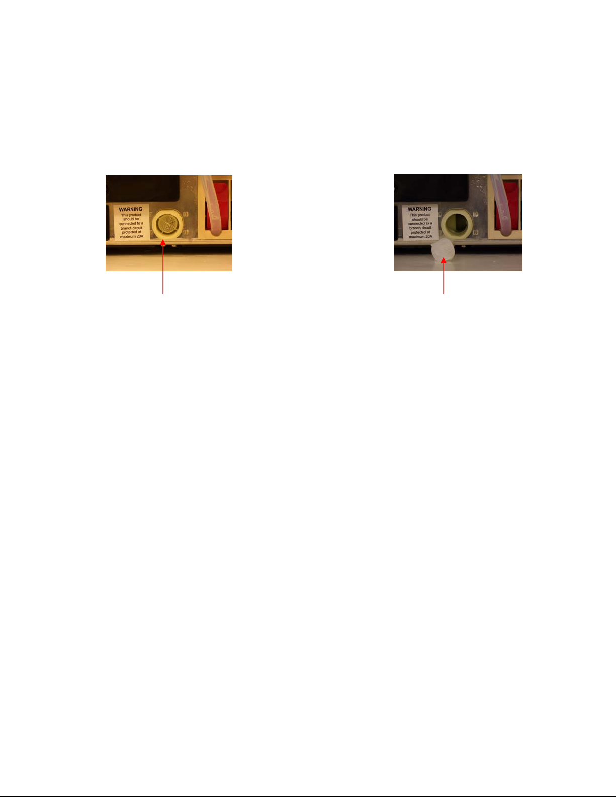
NOTE: There is a removable filter screen located in the Inlet Valve. If this screen should become
blocked by foreign material preventing water from flowing into the brewer, you can gently
remove the blocked screen using a pair of needle nose pliers and insert a new one. The part # for
the replacement screen is 01-201200-000.
Inlet Valve Screen
Inserted
Inlet Valve Screen
Removed
B3000 SERVICE MANUAL
60-200807-000, REV C 40
C. PUNCTURE MECHANISM MODULE (Located in the top front portion of the brewer)
See REMOVAL of OUTER PANELS (page 36). After completion of panel removal, the technician
must attach an ESD wrist strap to themselves and the metal base plate of the brewer.
1. Disconnect the Hot Water Valve tube from the top of the Bottom Hot water tank.
This hose is on the right hand side of the brewer looking at the front of the brewer.
Looking at the front of the brewer,
BREWERS ≤ 7505 BREWERS ≥ 7506
2. Raise the Puncture Mechanism handle and locate the two screws that hold the Puncture
Mechanism cover in place.
3. Remove these screws.
4. Push the cover back slightly and lift up to remove.
B3000 SERVICE MANUAL
60-200807-000, REV C 41

5. Release the hose clamp and remove the brew tube from the entrance needle assembly.
6. Loosen the four screws that hold the puncture module in place. There are two on each side. They
are captive screws so they will NOT come out completely.
Looking toward the back of the Puncture Mechanism Module area
7. Lift the Puncture Mechanism Module straight up about 2 inches (50mm) to disengage the unit
from a support mount. Support the module with your hand.
B3000 SERVICE MANUAL
60-200807-000, REV C 42

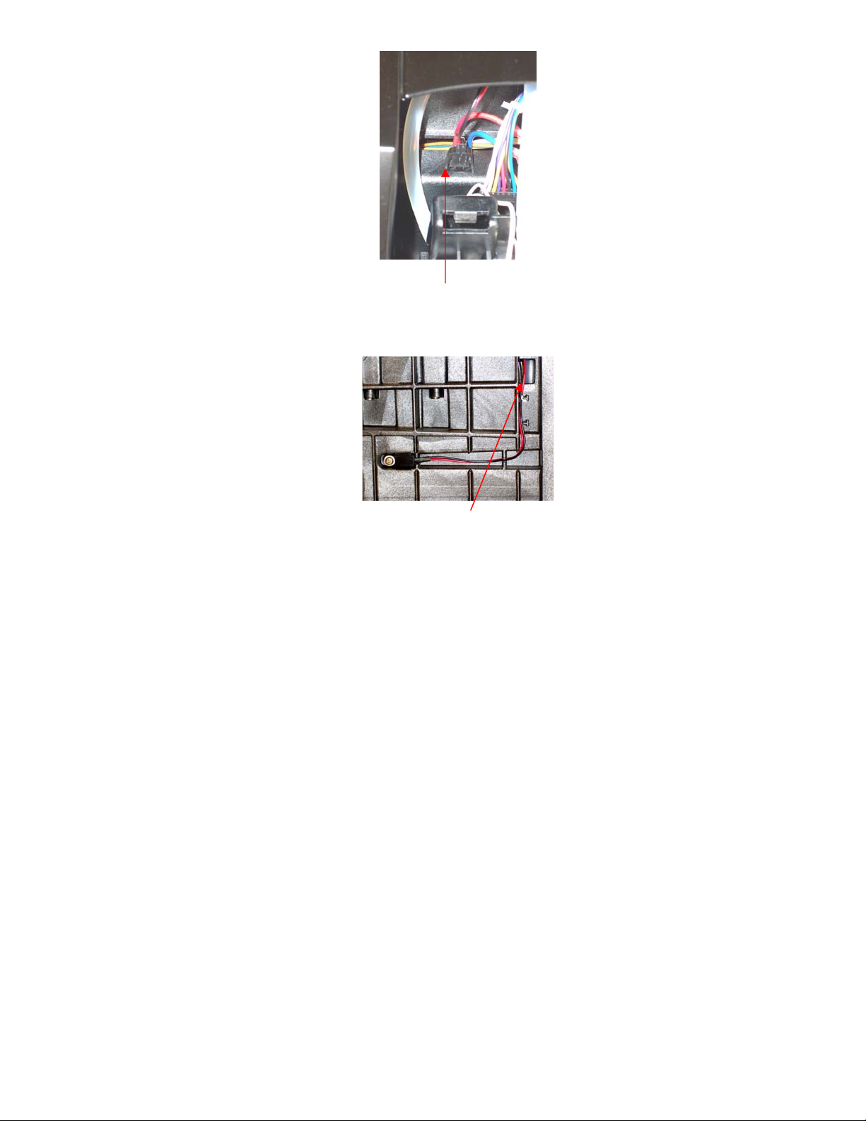
8. Disconnect the multi colored wire harness located to the left of the Hot Water Valve and the two
wires on the Hot Water Valve solenoid. There is no polarity for these wires.
9. Disconnect the Vent tube from the venting nipple on the left hand side of the module area.
10. The Puncture Mechanism Module can now be removed from the brewer.
NOTE: When reinstalling the new module connect the Hot Water Vent hose to the vent nipple
FIRST, and then connect the wire harness and two solenoid wires before you place the module on its
support post making sure that they are secure and tight. Reconnect the remaining hoses.
11. Conduct a BIT test (see appendix VII on page 85) to insure the proper function of the brewer.
B3000 SERVICE MANUAL
60-200807-000, REV C 43

D. HOT WATER VALVE ASSEMBLY (Located at the back of the Puncture Mechanism)
See REMOVAL of OUTER PANELS (page 36). After completion of panel removal, the technician
must attach an ESD wrist strap to themselves and the metal base plate of the brewer.
See REMOVAL of PUNCTURE MECHANISM (page 41).
1. Locate the Hot Water Valve on the back of the Puncture Mechanism.
2. Remove the two self tapping Phillips screws.
3. Loosen the large plastic nut at the bottom of the valve assembly.
B3000 SERVICE MANUAL
60-200807-000, REV C 44
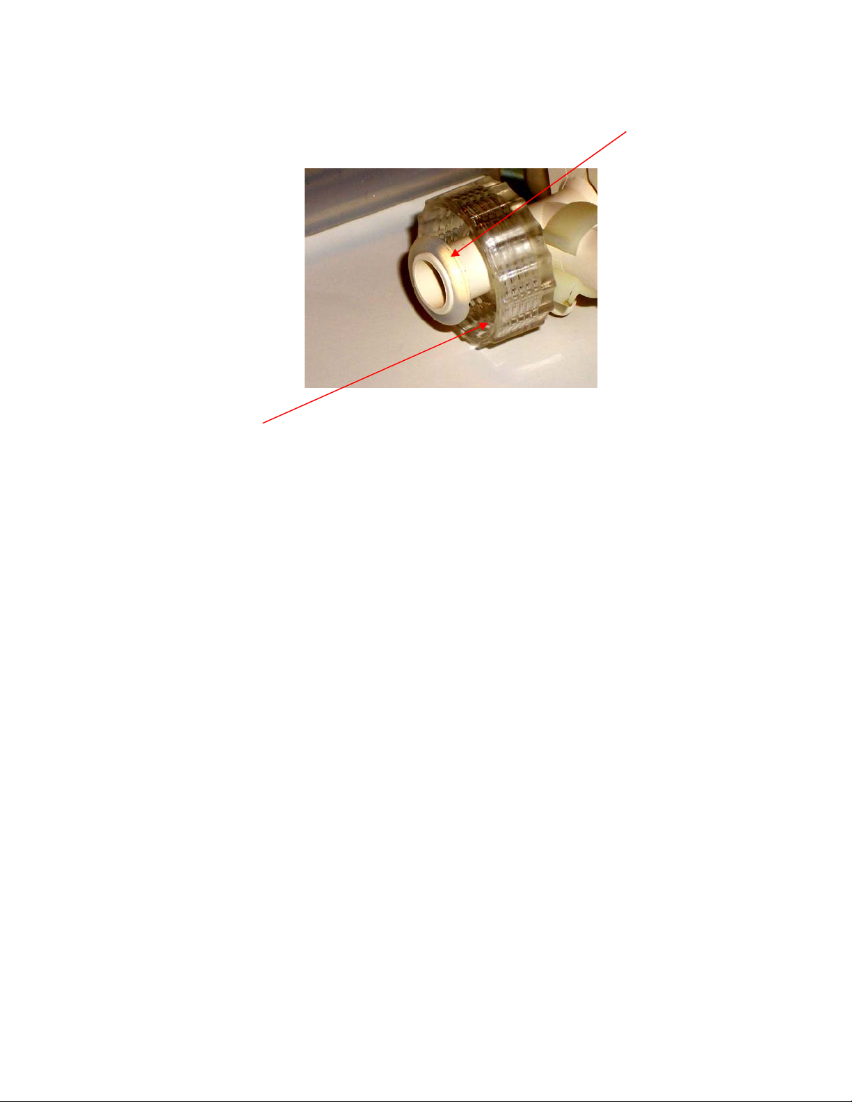
4. Gently pull OUT and UP the valve assembly.
5. Reinstall the new valve.
NOTE: When reinstalling the new valve, you MUST make sure that the “O” ring on the bottom of
the outlet tube is in place.
NOTE: The large Plastic Nut must be tight. Failure to do so will cause a leak when the hot water
feature is selected.
6. Conduct a BIT test (see appendix VII on page 85) to insure the proper function of the brewer.
B3000 SERVICE MANUAL
60-200807-000, REV C 45

E. HOT WATER TANK MODULE (Located in the back right side of brewer)
See REMOVAL of OUTER PANELS (page 36). After completion of panel removal, the technician
must attach an ESD wrist strap to themselves and the metal base plate of the brewer.
NOTE: Before disconnecting the two hoses on top of the module, make a note of where they are
attached. The LEFT hose comes from the Cold Water Tank. The RIGHT hose goes to the Puncture
Mechanism Module. These hoses MUST be reinstalled correctly. If they are not, then there will be no
water dispensed during the brew cycle. Needle nose pliers can be used to release the two hose clamps
that secure these hoses. Care must be taken when removing these clamps so that damage to these hoses
does not occur.
TO COLD WATER TANK TO PUNCTURE MECHANISM
1. Disconnect the two hoses on the top Hot Water Tank.
2. Disconnect the two wire harness connections on the right side of the Hot Water Tank module.
B3000 SERVICE MANUAL
60-200807-000, REV C 46

3. Disconnect the Hot Water Valve hose from the top of the bottom tank.
4. Locate the two screws at the top of the module. Loosen them fully. These are captive screws so
they will NOT come out completely.
5. Tilt the module toward you. It is secured on the bottom with mounting tabs. Lift the module out
carefully.
B3000 SERVICE MANUAL
60-200807-000, REV C 47

6. Remove the nut (6mm) securing the green ground wire on the left hand side of the Power
Module.
7. Disconnect the hose from the bottom tank.
8. The Hot Water Tank Module can be removed from the brewer.
9. Install the new module and connect all of the appropriate connections, hoses, and wires making
sure that they are secure and tight.
10. Conduct a BIT test (see appendix VII on page 85) to insure the proper function of the brewer.
B3000 SERVICE MANUAL
60-200807-000, REV C 48

F. COLD WATER TANK MODULE (Located at the top right of the brewer)
See REMOVAL of OUTER PANELS (page 36). After completion of panel removal, the technician
must attach an ESD wrist strap to themselves and the metal base plate of the brewer.
Looking at the right side of the brewer, take note of the cutout in the chassis near the top. You will see
one small hose and two larger ones.
1. Disconnect the small hose from the filter tee, just above the vent valve.
2. Disconnect the larger hose on the right.
3. Looking from the back of the brewer disconnect the multi colored wire harness that connects to
the right side of the Cold Water Tank.
B3000 SERVICE MANUAL
60-200807-000, REV C 49

4. Remove RED retaining clip from Murdock fitting. This is a quick release tube connection. Push
in on the collar, and pull out the tube.
5. Release clamp and disconnect the hose on the LEFT side of the top Hot Water Tank.
6. Disconnect the hoses on the top of each of the water pumps.
7. Disconnect the Cold Water Tank drain hose on the bottom right side of the tank.
B3000 SERVICE MANUAL
60-200807-000, REV C 50

8. Loosen fully the two screws that secure the Cold Water Tank to the chassis. They are captive
screws so they will NOT come out completely.
9. While gently holding the plastic tube from the Inlet Valve out of the way, remove the Cold
Water Module.
10. Install the new module; connect all of the appropriate connections, hoses and wires making sure
that they are secure and tight.
11. Conduct a BIT test (see appendix VII on page 85) to insure the proper function of the brewer.
B3000 SERVICE MANUAL
60-200807-000, REV C 51

G. COLD WATER PUMP MODULE (Located in the middle of the brewer)
See REMOVAL of OUTER PANELS (page 36). After completion of panel removal, the technician
must attach an ESD wrist strap to themselves and the metal base plate of the brewer.
Looking at the rear, in the middle of the brewer you will see the Cold Water Pump module.
1. Disconnect the hose on the top of each pump, two places.
2. Prior to disconnecting the four wire connections attached to bottom of the green water pumps
make a note of their respective connections.
B3000 SERVICE MANUAL
60-200807-000, REV C 52
NOTE: The wires must be reconnected to their proper connections when installing the new
module. Failure to do so will result in having extremely noisy pumps while they are in operation.
Make sure that Cold Water Tank drain hose is NOT pinched when reassembling.
3. Disconnect these four wires.
4. Loosen the captive screws holding the Power Module in place. (page 36) Gently slide out the
module. This will allow access to the manifold clips.
5. Disconnect the clamps and water hoses attached to the water manifold.
6. Remove the Multi Connector Tee manifold from new module. Set this aside. It will be used
when installing a new Power Module that does not come with this connection.
7. Locate the four screws holding the module to the chassis. Fully loosen these screws while
holding the CWP module. They are captive screws so they will NOT come out completely.
8. The Cold Water Pump Module can be removed from the brewer.
9. Install the new module and connect all of the appropriate connections, hoses, and wires making
sure that they are secure and tight.
10. Conduct a BIT test (see appendix VII on page 85) to insure the proper function of the brewer.
B3000 SERVICE MANUAL
60-200807-000, REV C 53

H. CONTROL PANEL MODULE (Located on the left front of the brewer)
CAUTION: The technician must attach an ESD wrist strap to themselves and the metal base
plate of the brewer or earth ground when replacing this module.
1. Open the K-Cup Bin door.
2. Tip the brewer back slightly and locate the two screws under the Control Panel. Remove these
screws completely.
3. Gently pull out and up on the module to remove from the brewer.
4. Look at the back of the Control Panel module, you will see the wire harness connector and a
hose union.
B3000 SERVICE MANUAL
60-200807-000, REV C 54

5. Disconnect the small tube at the union connection.
6. Disconnect the wire harness connection.
7. The Control Panel Module can now be removed.
8. Install the new module and connect all of the appropriate connections, hoses, and wires making
sure that they are secure and tight.
9. Conduct a BIT test (see appendix VII on page 85) to insure the proper function of the brewer.
B3000 SERVICE MANUAL
60-200807-000, REV C 55

I. FRONT DOOR MODULE (Located at the bottom of the brewer in the front).
NOTE: To remove the Front Door Module you MUST first remove the Control Module screws and
gently push the module up from the chassis to allow the TOP hinge pin to be removed. You do not need
to remove the Control Module or disconnect any connections.
1. Open the K-Cup bin door. Locate the wire harness cover plate and the three screws that secure
this cover
2. Remove the screws and cover plate.
3. Disconnect the cup sensor harness connection.
4. Open the Bin Door in order to remove the front decorative cover plate by releasing the plastic
tabs on the back of the plate.
One of five tabs
B3000 SERVICE MANUAL
60-200807-000, REV C 56

5. Locate the two hinge pins connecting the door to the brewer.
6. Using a flat screw driver, gently pry the hinge pins up and out.
7. Carefully pull the wire harness through the opening.
8. The Door Module can now be removed.
9. Install the new module and connect the appropriate wire connection, cover plate and reinsert the
hinge pins making sure that they are secure and tight.
10. Conduct a BIT test (see appendix VII on page 85) to insure the proper function of the brewer.
B3000 SERVICE MANUAL
60-200807-000, REV C 57

J. MAIN PCB MODULE (Located on the Left side of the brewer)
See REMOVAL of OUTER PANELS (page 36). After completion of panel removal, the technician
must attach an ESD wrist strap to themselves and the metal base plate of the brewer.
1. Remove the plastic bar in front of the Main PCB and disconnect the three wire harness
connections on the board.
2. Remove the four screws holding the PCB to the chassis. Set the PCB aside.
3. The Main PCB can now be removed.
4. Install the new module and connect the appropriate wire connections, and reinstall the protective
plastic bar.
5. Conduct a BIT test (see appendix VII on page 85) to insure the proper function of the brewer.
B3000 SERVICE MANUAL
60-200807-000, REV C 58

K. BIN FULL SENSORS (Located on each side of the of the K-Cup bin cavity)
See REMOVAL of OUTER PANELS (page 36). After completion of panel removal, the technician
must attach an ESD wrist strap to themselves and the metal base plate of the brewer. See REMOVAL
of MAIN PCB MODULE (page 58). After completion of PCB removal:
To remove the LEFT side LED, as you face the brewer.
1. Remove the screw holding the LEFT LED in place.
2. Disconnect the bin sensor. This connection is in the upper left corner of the main PCB area.
Unclip the MALE end of the connection from the chassis by squeezing the retaining tabs
together.
3. Carefully pull the MALE connector through the chassis opening behind the Cold Water Tank.
B3000 SERVICE MANUAL
60-200807-000, REV C 59

4. This completes the LEFT side bin sensor removal. Install the replacement sensor, the main PCB,
and plastic bar. Make sure that all connections are tight.
To remove the RIGHT side bin sensor
1. Remove the screw holding the RIGHT LED in place.
Looking at the front of the brewer,
BREWERS ≤7505 BREWERS ≥ 7506
2. Raise the Puncture Mechanism handle and locate the two screws that hold the puncture cover in
place.
3. Remove these screws.
4. Push the cover back slightly and lift up to remove.
B3000 SERVICE MANUAL
60-200807-000, REV C 60
5. Disconnect the SMALL connector toward the back of the Puncture Mechanism module area. If
it is easier, you can remove the Puncture Mechanism Module completely to gain access to this
connector.
6. Carefully pull the wire through the opening in the chassis and remove the RIGHT side bin
sensor.
7. This completes the RIGHT side bin sensor removal. Install the replacement sensor making sure
that all connections are tight. Attach the Puncture Mechanism Module cover and tighten its
retaining screws.
8. Conduct a BIT test (see appendix VII on page 85) to insure the proper function of the brewer.
B3000 SERVICE MANUAL
60-200807-000, REV C 61

De-Scaling Your Brewer
Mineral content in water varies from place to place. Depending on the mineral content of the water in
your area, calcium deposits or scale may build up in your brewer. Scale is nontoxic, but left unattended,
it can hinder brewer performance. De-scaling your brewer helps maintain the heating element and other
internal parts of the brewer that come in contact with water.
The brewer should be de-scaled every 6 months to ensure optimal performance. It is possible for
calcium deposits to build up faster, making it necessary to de-scale more often.
This brewer is equipped with sensors to detect when scale buildup is interfering with the performance of
the brewer. When this is detected, the brewer will alert you to perform a de-scaling procedure by
generating one of the following messages.
• De-scale soon
• De-scale now
NOTE: SAFETY GLASSES AND RUBBER GLOVES SHOULD BE WORN BEFORE
PROCEEDING WITH THE DE-SCALING PROCEDURE.
5. De-Scaling Procedures:
a) PREPARE
1. Make sure you have at least (80 ounces) of full strength citric acid such as CDCC Citric Acid
Powder or similar product on hand. You will also need an empty sink and a ceramic cup (do
not use a paper cup.) and a Flojet pump or similar.
2. Disconnect the brewer from the water supply and power it off. Drain both the hot and cold
tanks.
b) FILL AND CLEAN
1. Enter the PRIME mode (enter Menu mode and answer YES to HAS BREWER BEEN
DRAINED) and use a Flojet pump system to add de-scaling solution to the brewer.
NOTE: The water temperature for dissolving the powder can not be greater then 110° F.
Damage to the Flojet pump can occur.
Complete the PRIMING process.
2. After it has primed and heated, place a ceramic cup in the Drip Tray and run a brew cycle.
DO NOT USE A K-CUPP® Pportion pack, just press the Brew Button. Pour the contents of
the cup into the sink.
3. Now let the brewer stand for at least one hour.
4. Repeat the brew process, without K-Cups® at least 10 times, pouring the contents of the cup
into the sink after each cycle. We suggest using the largest brew size to speed the process.
Remember to open and close the brew handle between each cycle so the blue Brew lights
will flash.
B3000 SERVICE MANUAL
60-200807-000, REV C 62

5. Power off the brewer and drain both hot and cold water tanks.
6. Reconnect the brewer to the filtered cold water supply and follow the PRIME procedure to
refill the brewer.
7. Once the prime process is complete, power off the brewer and drain both hot and cold water
tanks again.
8. Power up the brewer and follow the PRIME procedure again, performing several (10)
cleansing brews to remove any residual taste from the citric acid.
NOTE: If the LCD screen still alerts you to perform a de-scale after completing the procedure,
repeat the de-scaling procedure.
B3000 SERVICE MANUAL
60-200807-000, REV C 63

6. Sanitizing / Cleaning the Puncture Mechanism (P.M.)
C
A. Sanitizing/Cleaning the B3000 Inlet Needle and Gasket
1. DEPRESS NEEDLE
PLATFORM TO EXPOSE
INLET NEEDLE AND THE
INLET NEEDLE GASKET.
LOOK FOR TEARS OR
OTHER NON FUNCTIONING
CONDITIONS.
FOR PROPER SANITIZING / CLEANING OF
THE PUNCTURE MECHANISM, THE
FOLLOWING ITEMS ARE RECOMMENDED.
A. DISHWASHING LIQUID SOLUTION OR
SOAP & WATER IN A SPRAY BOTTLE.
B. MINI SCRUB BRUSH FOR CRAMPED AND
TIGHT AREAS [i.e. AS SHOWN, McMASTERCARR PT NO. 7243T22].
C. CLOTH FOR WIPING.
D. ACCESS TO A SINK (IDEALLY WITH FRUIT
SPRAYER) OR A BUCKET OF WATER FOR
RINSING. SEE IMAGES 18 AND 19.
2. WHILE DEPRESSING
THE PLATFORM
REMOVE STUBBORN
PARTICLES BY USING
BRUSH AND WATER.
3. WIPE THE NEEDLE AND
GASKET AREA CLEAN
USING A DRY CLOTH.
PERFORM THREE
CLEANSING BREWS
(BREWS WITHOUT KCUPS) TO RINSE OUT
NEEDLE.
B3000 SERVICE MANUAL
60-200807-000, REV C 64

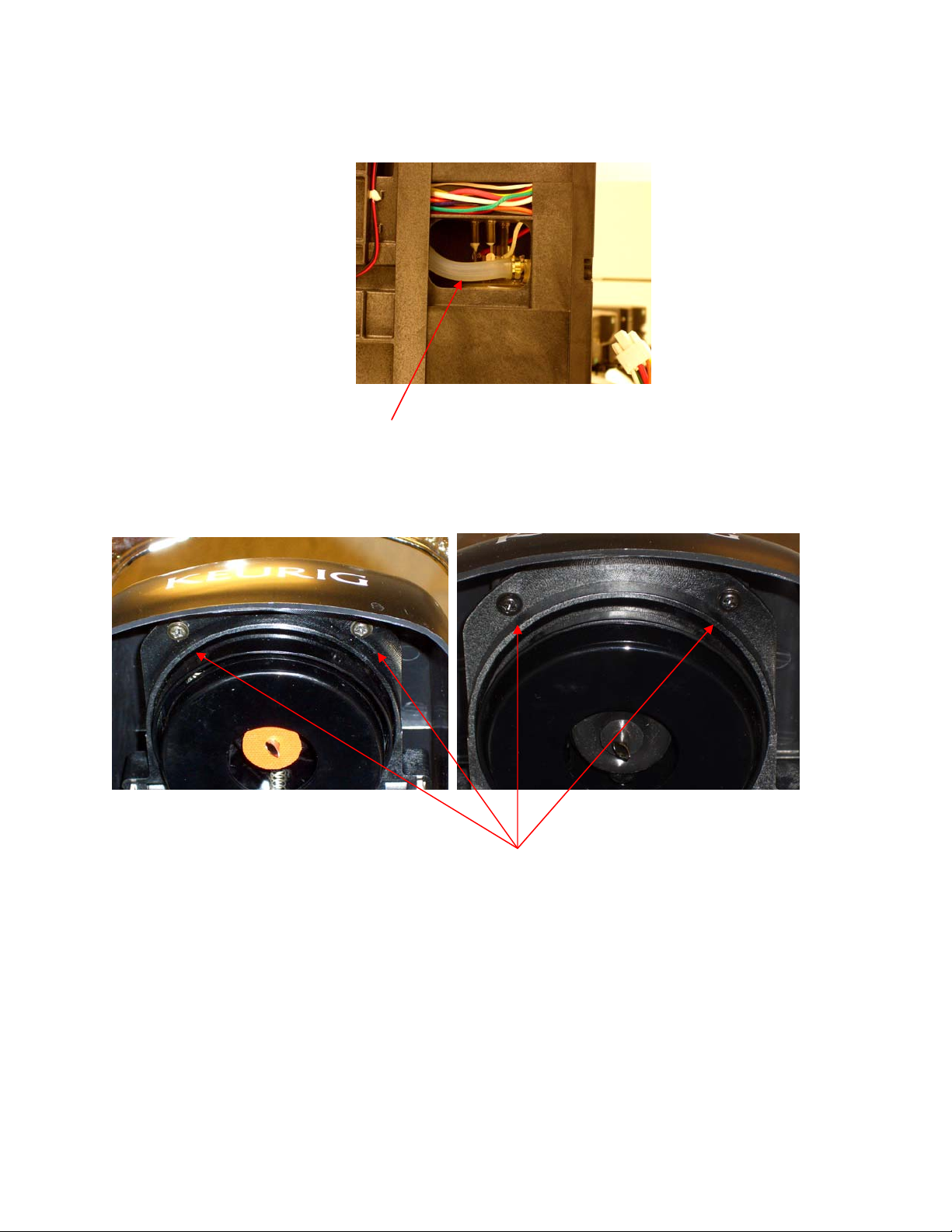
B. Sanitizing/Cleaning the Puncture Mechanism (P.M.)
1. P.M. REMOVED AS
DESCRIBED IN THIS
MANUAL.
4. TO REMOVE THE BOTTOM
P.M. COVER, REMOVE THE
THREE SCREWS INDICATED
ABOVE.
2. REMOVE LOWER P.M.
COVER BY REMOVING
THE TWO SCREWS AS
INDICATED ABOVE.
5. HERE THE P.M. IS
SHOWN WITH THE
BOTTOM P.M.COVER
REMOVED.
3. HERE THE P.M. IS
SHOWN WITH THE LOWER
P.M. COVER REMOVED.
6. THE K-CUP HOLDER,
LOWER RIGHT, SHOULD BE
REMOVED AND SANITIZED
AS DESCRIBED IN THE USE
& CARE GUIDE ON PAGE
12.
B3000 SERVICE MANUAL
60-200807-000, REV C 65

7. THE MODULE FRAME
SHOULD BE SPRAYED
WITH A SOAPY SOLUTION
OR MILD DETERGENT.
10. USE THE DETAILING
END OF THE BRUSH TO
REACH INSIDE THE MODULE
FRAME TO REMOVE DEBRIS
8. THE MODULE CAN BE
MANEUVERED SO ALL
AREAS CAN BE REACHED
BY THE SPRAY.
11. A CLOTH CAN BE USED
TO WIPE THE FRAME
CLEAN AND TO DRY IT
AFTER RINSING UNDER A
.
FAUCET, OR RINSING WITH
A FRUIT SPRAYER, OR
RINSING IN A BUCKET OF
WATER.
9. USE SMALL SCRUB
BRUSH TO REMOVE
DEBRIS FROM THE
MODULE.
12. USE THE SAME SPRAY
ON THE UNDER COVER.
B3000 SERVICE MANUAL
60-200807-000, REV C 66

13. USE THE SCRUB
BRUSH ON THE UNDER
COVER AS NECESSARY.
16. BRUSH PART AS
NECESSARY.
14. USE A CLOTH WIPE AS
REQUIRED. RINSE UNDER
FAUCET OR IN BUCKET OF
15. PREP THE LOWER
P.M. COVER WITH
CLEANING SPRAY.
WATER.
17. WIPE THE PART WITH
A CLOTH AS NECESSARY.
RIINSE UNDER FAUCET OR
IN A BUCKET OF WATER.
18. RINSE FRAME IN
BUCKET OF WATER IF
AVAILABLE, TAKING CARE
NOT TO WET ELECTRICAL
COMPONENTS.
B3000 SERVICE MANUAL
60-200807-000, REV C 67

19. REMOVE FRAME FROM
BUCKET ALLOWING WATER
TO DRAIN.
20. MODULE CAN BE
PLACED ON TOWEL TO
ALLOW FOR FINAL DRAINIG
BEFORE WIPING.
21. RE-ASSEMBLE MODULE
TO BE RE-INSTALLED IN
BREWER
.
B3000 SERVICE MANUAL
60-200807-000, REV C 68

IV. Product Warranty Information
WARRANTY
Set forth below is a summary of warranty information for your Keurig B3000 brewer effective as of the date the
Service Manual was printed. The complete details of Keurig’s warranty is set forth in the Non-Exclusive
Distributorship Agreement, as amended from time to time, between Keurig and the original purchaser of this
Brewer.
Keurig warrants that your Keurig B3000 Brewer will be free of defects in materials or workmanship under normal
use for one year from the date of delivery to the original purchaser. Keurig will, at its option, repair or replace the
Brewer without charge upon its receipt of proof of such delivery date. If a replacement Brewer is necessary, the
replacement Brewer may be new or reconditioned. If a replacement Brewer is sent, it will carry the remaining
warranty of the original product. Keurig will cover all shipping costs for authorized warranty returns.
This warranty only applies to Brewers operated in the United States and Canada. This warranty gives you specific
legal rights, and you may also have other rights that vary from state to state and, in the case of Canada, from
Province to Province.
LIMITED WARRANTY
THIS WARRANTY DOES NOT COVER CONSEQUENTIAL OR INCIDENTAL DAMAGES SUCH AS
PROPERTY DAMAGE AND DOES NOT COVER INCIDENTAL COSTS AND EXPENSES
RESULTING FROM ANY BREACH OF THIS WARRANTY, EVEN IF FORSEEABLE. Some states or
Provinces do not allow the exclusion or limitations of incidental or consequential damages, so the above
limitation or exclusion may not apply to you depending on the state or Province of purchase.
THIS WARRANTY IS EXCLUSIVE AND IN LIEU OF ANY OTHER EXPRESS WARRANTY, WHETHER
WRITTEN OR ORAL. THE DURATION OF ANY IMPLIED WARRANTIES, INCLUDING BUT NOT
LIMITED TO ANY IMPLIED WARRANTIES OF MERCHANTABILITY OR FITNESS FOR A
PARTICULAR PURPOSE, IS EXPRESSLY LIMITED TO THE PERIOD OF DURATION OF THIS LIMITED
WARRANTY. Some states or Provinces do not allow limitations on how long an implied warranty lasts, so the
above limitation may not apply to you depending on the state or Province of the purchase.
OTHER WARRANTY EXCLUSIONS
The limited warranty set forth above shall not apply to any Brewer, and Keurig shall have no obligation under
such warranty or otherwise, under any of the following circumstances:
• The Brewer is repaired or attempted to be repaired with replacement parts that have not been purchased
from or approved by Keurig;
• The Brewer is improperly or negligently installed, repaired, modified or operated, including, but not
limited to operation of the Brewer without an Ominpure KQ8 or equivalent water filtration system;
• The Brewer is abused or neglected, including, but not limited to, failure to clean or remove mineral
deposit accumulations periodically from the Brewer in accordance with Keurig user or service
instructions or manuals;
• The Brewer is damaged in transit to Keurig due to improper packaging; or
• The Brewer is damaged after delivery from Keurig to the original purchaser or its agent, as applicable.
B3000 SERVICE MANUAL
60-200807-000, REV C 69

OBTAINING WARRANTY SERVICE
Keurig Brewers are high quality appliances and, with proper care, are intended to provide years of satisfying
performance. However, should the need arise for warranty service, simply call Keurig Field Support at our toll
free number 1-888-CUP-BREW (1-888-287-2739). Please do not return your brewer for servicing without first
speaking to Keurig Field Support to obtain an Authorization to Return number (ATR). Keurig brewers returned
without an ATR number will be returned to the sender, at the sender’s expense, without servicing.
B3000 SERVICE MANUAL
60-200807-000, REV C 70

V. Certifications and Specifications
Regulatory Compliance
The Keurig B3000 Brewer will comply with:
UL 197
Commercial Electric Cooking Appliances
ANSI / NSF 25 (applies to brewers F0009546 and higher)
Commercial Cooking, Rethermalization, and Powered Hot Food Holding and Transport Equipment.
CAN/CSA C22.2 No. 109 – M1981
Commercial Cooking Appliances
NAMA Listed
National Automatic Merchandising Association
Specifications
Size………………………………………12 Inches W X 21.3 Inches D X 17.5 Inches H
305 mm W X 540 mm D X 443mm H
Weight…………………………………..35 Pounds Empty (Shipping Weight 38 Pounds)
15.88 kilograms Empty (Shipping Weight 17.24 kilograms)
Tank Volumes………………………….Hot Water Tank, 1400 ml
Hot Water Tank, 47.34 oz
Cold Water Tank, 450 ml
Cold Water Tank, 15.22 oz
Brew Sizes………………………………4 oz, 6 oz, 8 oz or 10 oz
118 ml, 177 ml, 236 ml or 296 ml
Electrical……………………………….125 VAC, 60 Hz, 15 Amp, Three Prong Plug. 1400 Watts
Plumbing……………………………….3/4 Inch Male Garden Hose Fitting
Water Supply Pressure………………. 40 to 125 psi
0.03 kg/mm² to 0.08 kg/mm²
B3000 SERVICE MANUAL
60-200807-000, REV C 71

VI. ACCESSORIES APPENDIX
1. Water Filter Kit (Part Number 5025)
Keurig requires the use of a water filtration system for the B3000. The Omnipure KQ8A filter is
recommended. This filter has both a Charcoal filter medium for removing chlorine, taste and odor, plus
phosphate for the reduction of lime build up inside the brewer.
NOTE: The phosphate only slows down the build up of lime. It does not eliminate it.
Keurig offers a filter kit for its brewers. The kit (Part Number 5025) contains:
1 – Omnipure KQ8A filter
1 – Filter head
1 – Mounting bracket with screws
There is no water connection components provided in this kit. The type of connectors used to attach the
water supply to the filter is left up to the distributor.
B3000 SERVICE MANUAL
60-200807-000, REV C 72

2. Coin Changer Accessory (Part Number 5557)
The installation of the B3000 Coin Changer Accessory is covered in the installation guide provided with
each coin changer accessory kit. Details for the installation of the changer are provided as an appendix
of this manual. If a copy is needed, asked for part number 60-200814-000.
Introduction:
This guide will detail how to install the coin mechanism that will enable coin operation of the Keurig
B3000 Commercial Brewer. This guide is intended for Keurig authorized distributors (KADs). The
guide covers attaching the B3000 Coin Changer Accessory to the brewer and installing the coin
mechanism inside the B3000 Coin Changer Accessory. The coin mechanism covered in this installation
guide is the COINCO Quantum Pro XXQ-G700 Series. The mechanism is shown below. The use of a
coin mechanism is determined and acquired by a KAD. For details regarding the operation and
components of the coin mechanism, please refer to the manufacturer’s user manuals.
B3000 SERVICE MANUAL
60-200807-000, REV C 73

The B3000 Coin Changer Accessory:
The B3000 Coin Changer Accessory is custom designed to be used exclusively with the B3000
Commercial Brewer and the aforementioned coin mechanism. All the necessary hardware and cables
for assembling the B3000 Coin Changer Accessory are included. See figures 1 and 2. The items
included in the accessory kit are:
1. Coin changer cabinet
1
3 2
2. Brewer coin platform
3. High capacity platform
4. Brewer-cabinet plate
5. Accessory package
A. Screws 5 ea.
B. Control cable
C. Keys 2 ea.
5
Figure 1 Figure 2
4
Procedure for Attaching the Coin Changer Accessory to the Brewer: (Without a Platform Unit)
The step by step procedure for attaching the coin changer accessory is as follows:
1. Place brewer platform on cabinet top where brewer will be in service. See Figure 3 below.
Figure 3
B
A
C
B3000 SERVICE MANUAL
60-200807-000, REV C 74
2. Join the coin changer cabinet to platform by placing the ‘hooks’ inside the platform slot. See
figures 4 and 5 below.
DETENTS
FOR
BREWER
Figure 5
Figure 4
Figure 5
3. Place brewer on the platform such that the rubber feet of the brewer fit into the detent areas on
the platform and the brewer rests on top of the coin changer cabinet protrusions. See figure 6
below.
Figure 6
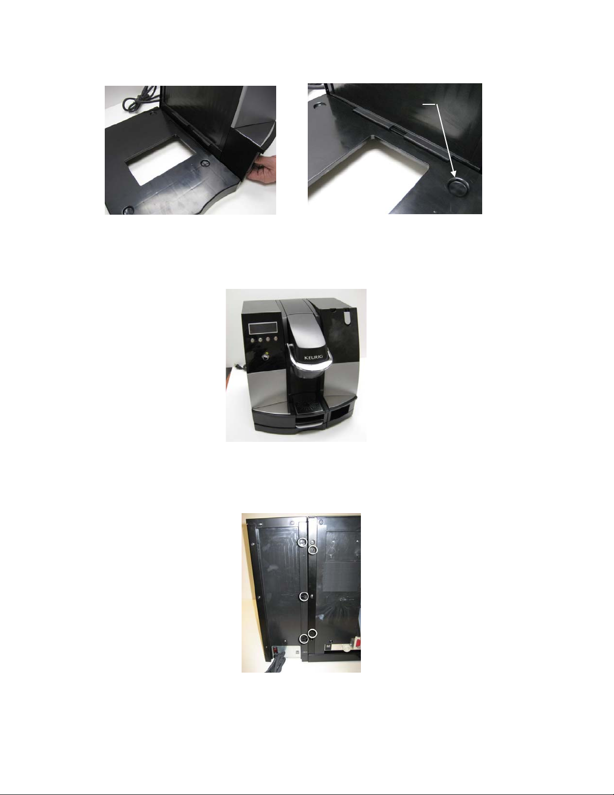
4. At the rear of the assembled brewer-coin changer cabinet locate the five holes for mounting the
Brewer-cabinet plate. Remove the five screws from the plastic accessory bag. See figure 7
below.
Figure 7
B3000 SERVICE MANUAL
60-200807-000, REV C 75
5. Fasten the brewer-cabinet plate to the cabinet (three screws) and to the brewer (two screws).
See figures 8 and 9 below.
Figure 8
Figure 9
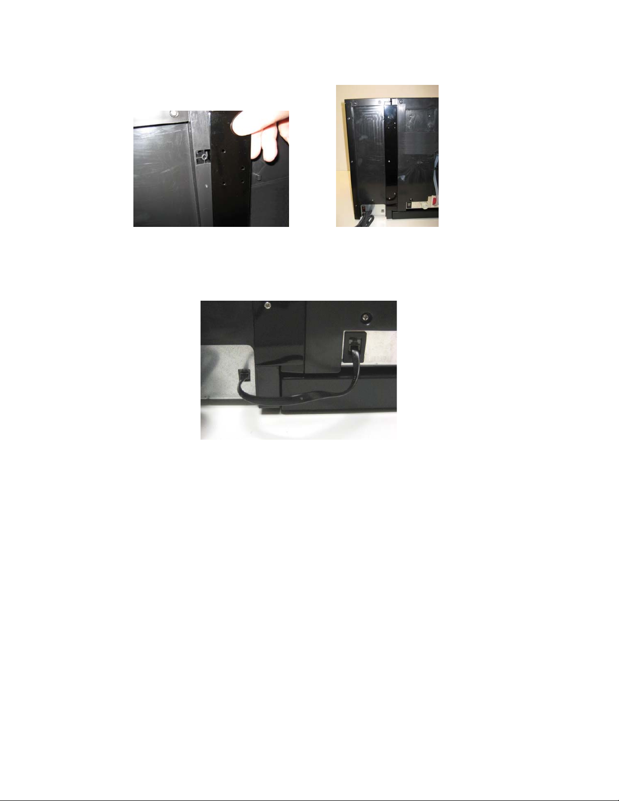
6. Connect the control cable to both RJ11 connectors on the rear of the brewer and the coin
changer cabinet. See figure 10 below.
Figure 10
B3000 SERVICE MANUAL
60-200807-000, REV C 76

Installing the Coin Mechanism:
The step by step procedure for installing the coin changer is as follows:
1. Unlock the coin changer cabinet fascia [Figure 11] and remove it by lifting up at coin retrieval
opening [Figure 12]. Remove the top panel of the coin changer cabinet by unscrewing the two
screws at the rear of the unit [Figure 13] and sliding the panel rearward and lifting up.
Figure 11
2. Mount and connect the coin mechanism.
Figure 14
Locate the mounting
screws of the cabinet
shown in fig 14.
Slide coin mechanism
back into the cabinet
insuring the cabinet
mounting screws locate
into the holes at the
back of the unit shown
in fig 15. Note, some
changers may require a
slight deflection of the
cabinet side panels
during insertion.
Coin
retrieval
opening
Figure 15
Figure 12
Figure 16
Once the coin
mechanism is seated
properly connect the
unit to the connector as
shown and route cord
as shown in fig 16.
Figure 13
Figure 17
Replace the top panel.
When mounted properly
the coin mechanism should
have a flush look and feel
as shown in fig 17.
B3000 SERVICE MANUAL
60-200807-000, REV C 77

3. Tightening the Mounting Screws. See Figures 18 and 19 below. The mechanism is shown outside of
the coin accessory cabinet.
Coin slot
Figure 19 Figure 18
To tighten the mounting screws on the
Quantum Pro device the upper panel
must be opened. To open the panel
depress the tab and pull back on the
coin slot to rotate the panel toward
you and down.
Once the panel is rotated down the
screws will be exposed for tightening.
After tightening rotate the panel up
and back until it snaps closed.
4. Load coins in the coin changers as appropriate. Please refer to the respective unit’s manual for
direction on how to load coins.
B3000 SERVICE MANUAL
60-200807-000, REV C 78

Procedure for Setting the Brewer to Coin Operation:
Procedure:
1. Attach coin changer unit to brewer per assembly instructions.
2. Connect patch cable to female RJ11 connectors on the back of the B3000 brewer and the coin
unit.
3. Plug-in each units cords to outlets.
4. Power both units. Switches are located on the rear bottom of both units.
5. To enable the coin changer unit, access the menu button through the front door of the B3000
brewer. The menu button is located inside the brewer at the top (see figure 1). Press the menu
button 4 times within 4 seconds after powering the brewer to access the menu.
6. Once the menu is accessed the display will look like this (set language):
7. Press the ‘Next’ button.
8. The display will look like this (number of brews):
9. Press the ‘Next’ button.
Figure 1
FIGURE 1
B3000 SERVICE MANUAL
60-200807-000, REV C 79

10. The display will look like this (was brewer drained):
11. Press the ‘Yes’ or ‘No’ button as appropriate.
12. The display will look like this (set vend / no vend):
13. Press ‘Adjust’ button to ‘Vend at Set the price’ (image on left below). Then press next button.
14. The display will look like the image on the right below. Adjust price by pressing the + or –
button to get desired price. Adjustments are in $0.05 increments.
15. Press the ‘Next’ button after selection is made.
B3000 SERVICE MANUAL
60-200807-000, REV C 80
16. The next display will read ‘Set the Brew Temp’ at the display continue to press the next button
until the following display is seen, and then the brewer and coin changer unit are ready for
operation.
WARNING: The product should be connected to a branch circuit protected at maximum 20A.
DANGER: Risk of electric shock. This unit has two power supply cords. Disconnect all power before
installing coin or credit mechanism.
CAUTION: Risk of Fire or Electric Shock. Only operate this appliance with Coin Changer Mechanism,
Coin Acceptors Inc. Model Quantum Pro XXQ-G700 Series in Place.
DANGER: For Data Connection with Coffee Maker B3000 only. Do not connect to public telephone
network.
Only use with Keurig Model B3000 Commercial Coffee Maker.
Suitable for indoor use only.
B3000 SERVICE MANUAL
60-200807-000, REV C 81

3. Platform Unit (Part Number 5558)
The assembly of the B3000 Platform accessory is covered in the installation guide provide with each
platform kit. Details for the installation of the changer are provided as an appendix of this manual. If a
copy is needed, ask for part number 60-200993-000.
Platform
Chute
Storage Bin
Fig 1. Contents of the Platform Kit #5558
Lift up the trapdoor in
the bottom of the
brewer.
Fig 2. Brewer placed on platform
B3000 SERVICE MANUAL
60-200807-000, REV C 82

Place the Chute
in position
Fig 3. Install Chute
Fig 4. Chute in position
B3000 SERVICE MANUAL
60-200807-000, REV C 83

Fig 5. Completed assembly
B3000 SERVICE MANUAL
60-200807-000, REV C 84

VII BIT Testing
Manufacturing Built In Test (BIT)
The B3000 brewer has the ability of performing diagnostic tests to verify if most of the critical system
elements are functioning properly. For brewers from 1 – 7505 see page 85. For brewers 7506 and above
see page 89.
To initiate the B3000 BIT, follow the procedure below:
• Start with an empty, cold brewer
• While powered off; Press and hold the Menu Button
• Turn power on (Hard Power)
• Release the Menu Button
• Press the Center Left Button 4 times within 2 seconds of applying power
Notes:
• The top line of the display shows:
o The test number
o The tested component / instructions
• The second line of the display shows:
o The most likely module bad, if fail.
For example
01:
LEFT SW & LED
MODULE:
• If any test fails the criteria, BIT will halt at that failed test number
• Ensure that the Entrance Needle is blocked before the start of the test with a pressure
gauge. If not, BIT cannot advance beyond Test No. 22.
• These test fixtures are required:
Plug in coin IF loop back plug. (Figure 1) (Use P/N 03-200922-000 for ordering)
Ampere meter for power. (optional, can ignore current draw check)
Entrance needle blocker with pressure gauge. (optional, can use a piece of plugged tubing)
Coin interface loop-back plug (short transmit to receive) (optional, can stop at this test)
Vent clamp (optional, can use finger to block tube opening)
Inlet valve plug (optional, can use normal water hook-up)
• Note that after a few passes of the BIT, the brewer will be too warm to pass the
temperature sanity check.
BIT loops on the last test forever. Power down to continue.
CTRL-PCB
Figure 1.
Modified RJ11 cable for coin unit test
B3000 SERVICE MANUAL
60-200807-000, REV C 85

T
EST
NO.
(TN)
1. Left Button /
LED, LCD Pixels
mostly on
ESTS: INDICATIONS
T
“LCD
MESSAGE” /
BUTTON LEDS
“01:
LEFT SW &
LED?”
“MODULE: CTRL-
PCB”
Left LED blinks
2. Center Left Button /
LED
“02: CTR-LEFT SW &
LED?”
“MODULE:
CTRL-
PCB”
C Left LED blinks
3. Center Right Button/
LED
“03: CTR-RIGHT SW &
LED?”
“MODULE:
CTRL-
PCB”
C Right LED blinks
4. Right Button /
LED
“04:
RIGHT SW &
LEDS?”
“MODULE:
CTRL-
PCB”
R LED blinks
5. Muglight “05: MUG LEDS?”
“MODULE:
M-PCB,
BR-HEAD”
R LED blinks
6. Door Switch (Open) “06: OPEN HANDLE”
“MODULE:
BR-HEAD”
7. Door Switch (Close) “07: CLOSE HANDLE”
8. Water Sensor (water
level high)
9. Water Sensor (water
level low)
10. Mug Sensor
(blocked)
11. Mug Sensor
(unblocked)
12. Bin Sensor
(blocked)
13. Bin Sensor
(unblocked)
14. K-Cup® Sensor
(blocked)
“MODULE:
“08: FLIP BREWER
OVER”
“MODULE:
“09: FLIP BREWER
BACK”
“MODULE:
“10: BLOCK MUG”
“MODULE:
“11: UNBLOCK MUG”
“MODULE:
“12: BLOCK BIN”
“MODULE:
“13: UNBLOCK BIN”
“MODULE:
“14: OPEN KCUP”
“MODULE:
BR-HEAD”
CWT”
CWT”
SENSORS”
SENSORS”
SENSORS”
SENSORS”
BR-HEAD”
OTES ACTION TO
N
CONTINUE
Check left LED,
LCD mostly on
Check center left
LED
Check center right
LED
Check right LED
Check mostly lit
pixels.
Press Left Button
Press Center Left
Button
Press Center Right
Button
Press Right Button
Check Mug light on Press Right Button
Raise the Handle
Lower the Handle
Flip brewer over
Flip brewer back
Block Mug
Unblock Mug
Block Bin
Unblock Bin
Done by opening the Raise the handle
B3000 SERVICE MANUAL
60-200807-000, REV C 86

15. K-Cup® Sensor
(unblocked)
16. Brew tank
Thermistor @
“15: CLOSE KCUP”
“MODULE:
“16:
BREW TEMP”
“MODULE:
BR-HEAD”
HWT”
ambient temperature
17. Pre-heat tank
Thermistor @
“17:
PREHEAT TEMP”
”
MODULE: HWT”
ambient temperature
18. 120 Hz Clock (60
Hz Power)
“18: 120 HZ CLOCK”
“MODULE:
M-PCB”
19. Heaters off “19: HEATER LOW
AMP?”
“MODULE:
POWER”
R LED blinks
20. Brew Tank
Heating Element
power
“20:
BREW 12A?”
“MODULES:
HWT”
POWER,
R LED blinks
21. Preheat Tank
Heating Element
power
“21:
PRE 12A?”
“MODULES:
HWT”
POWER,
R LED blinks
22. Initial Air
Pressurization with
Water Pump,
Pressure transducer
“22:
CW PUMP.
CLAMP&PSI-M”
“MODULE:
PCB,
LEAK”
CWP, C-
R LED blinks
23. Vent Valve opening
under low pressure
24. Full HWT air
Pressurization with
Brew Pump.
Pressure transducer
calibration
“23: VV OPEN LO-PSI”
“MODULE:
“24:
BREW PUMP
CWT”
7PSI?”
“MODULE:
CWT,
LEAKS”
R LED blinks if 7psi
25. Half CWT
Pressurization by
“25:
VV OPEN HI-PSI”
“MODULE: CWT”
sharing;
Vent Tubes
Vent Valve opening
under full over
pressure
26. CWT, Vent Tubes
Leaks
“26:
CWT LEAK”
“MODULE: CWT,
LEAKS”
door. Ejection blocks
Lower the handle
sensor!!
Auto Cont. if OK
Auto Cont. if OK
Auto Cont. if OK
Press Right Button
if less than 1 amp
Heating Element on
for 3 seconds –
Verify 12A
Heating Element on
for 3 seconds –
Verify 12A
CWP on for 2
seconds. Verify
>0.25 psi
Press Right Button
if OK, Center Right
to repeat
Press Right Button
if OK, Center Right
to repeat
Clamp CWT vent
tube, add pressure
gauge. Press Right
Button when ready.
Vent Valve open for
2 seconds – Verify
Auto Continue if
OK
<0.1 psi
Runs Brew Pump
until 7 psi. Checks
pressure drop below
Press Right Button
when lit and gauge
at 7 psi
.21 psi (7 psi - 3%)
over 5s. If pass, R
LED lights.
Opens VV.
(tanks equalize)
Auto Continue if
OK
Wait 5 seconds –
check for pressure 35 psi.
Checks pressure drop
below .21 psi (4 psi)
Auto Continue if
OK
5% over 5 seconds
B3000 SERVICE MANUAL
60-200807-000, REV C 87

27.
HW Dispense valve “27:
28. Transmit and receive
a “1” and “0”
through the coin IF
HWD VALVE”
“MODULE:
“29:
VEND I/F
BR-HEAD”
LOOPBACK”
“MODULE:
M-PCB,
Open VV. Open
HWDV. Verify
HWT <0.1 psi after 2
seconds
Auto Continue if
Auto Continue if
OK
OK
PWR-PANEL”
29. Done “30: PASS, !!!!”
Power off Stop
“DONE”
Test 24 pressurizes the entire hot water part of the brewer, thus checking for leaks in:
• All vent line components from the tank through the VV. Tested open in 25
• The HWT
• All fill line components from the HWT through the CWP. Tested open in 22
• All brew line components. Not tested open
Test 25 pressurizes the cold water part of the brewer, thus checking for leaks in:
• The vent line from the CWT to the bin. Not tested open
• The CWT
• The tube from the CWT to the CWP. Tested open in 22
• The inlet valve and high pressure tubing. (to 4 psi) Tested open in 28
Some components are not tested. The functionality was tested by manufacturing.
• Float valve
• CWT and HWT drains open
• Dispense line from Dispense Valve to Mug
• TCOs opening and TCO sensors
• Conductive probes and power
• Inlet Valve
• Hi-Pot
The coin IF loopback plug shorts the transmit to receive pin (RJ11 pins 3 and 4).
B3000 SERVICE MANUAL
60-200807-000, REV C 88

Bit Test for brewers 7506 and above
T
EST
NO.
ESTS: INDICATIONS
T
“LCD
MESSAGE” /
BUTTON LEDS
1. Left Button /
LED, LCD Pixels
mostly on
“01:
LEFT SW &
LED?”
“MODULE: CTRL-
PCB”
Left LED blinks
2. Center Left Button /
LED
“02: CTR-LEFT SW &
LED?”
“MODULE:
CTRL-
PCB”
C Left LED blinks
3. Center Right Button/
LED
“03: CTR-RIGHT SW &
LED?”
“MODULE:
CTRL-
PCB”
C Right LED blinks
4. Right Button /
LED
“04:
RIGHT SW &
LEDS?”
“MODULE:
CTRL-
PCB”
R LED blinks
5. Mug-light “05: MUG LEDS?”
“MODULE:
M-PCB,
BR-HEAD”
R LED blinks
6. Door Switch (Open) “06: OPEN HANDLE”
“MODULE:
BR-HEAD”
7. Door Switch (Close) “07: CLOSE HANDLE”
8. Water Sensor (water
level high)
9. Water Sensor (water
level low)
10. Mug Sensor
(blocked)
11. Mug Sensor
(unblocked)
12. Bin Sensor
(blocked)
13. Bin Sensor
(unblocked)
“MODULE:
“08: FLIP BREWER
OVER”
“MODULE:
“09: FLIP BREWER
BACK”
“MODULE:
“10: BLOCK MUG”
“MODULE:
“11: UNBLOCK MUG”
“MODULE:
“12: BLOCK BIN”
“MODULE:
“13: UNBLOCK BIN”
“MODULE:
BR-HEAD”
CWT”
CWT”
SENSORS”
SENSORS”
SENSORS”
SENSORS”
OTES ACTION TO
N
CONTINUE
Check left LED,
LCD mostly on
Check center left
LED
Check center right
LED
Check right LED
Check for mostly lit
pixels.
Press Left Button
Press Center Left
Button
Press Center Right
Button
Press Right Button
Check Mug-light on Press Right Button
Raise the Handle
Lower the Handle
Flip brewer over
Flip brewer back
Block Mug
Unblock Mug
Block Bin
Unblock Bin
B3000 SERVICE MANUAL
60-200807-000, REV C 89

14. K-Cup Sensor
(blocked)
15. K-Cup Sensor
(unblocked)
16. 120 Hz Clock (60
Hz Power)
“14: OPEN KCUP”
“MODULE:
BR-HEAD”
“15: CLOSE KCUP”
“MODULE:
BR-HEAD”
“16: 120 HZ CLOCK”
“MODULE:
M-PCB”
17. PT Sanity check “17: LOW PRESSURE
CHECK”
“MODULE:
CTRL-
PCB”
18. Initial Air
Pressurization with
Water Pump,
Pressure transducer
“18:
CW PUMP.
CLAMP&PSI-M”
“MODULE:
PCB,
LEAK”
CWP, C-
R LED blinks
19. Vent Valve opening
under low pressure
20. Full HWT air
Pressurization with
Brew Pump.
Pressure transducer
“19: VV OPEN LO-PSI”
“MODULE:
“20:
BREW PUMP
CWT”
7PSI?”
“MODULE:
HWT,
LEAKS”
calibration
21. Half CWT
Pressurization by
“21:
VV OPEN HI-PSI”
“MODULE: CWT”
sharing;
Vent Tubes
Vent Valve opening
under full over
pressure
22. CWT, Vent Tubes
Leaks
“22:
CWT LEAK”
“MODULE: CWT,
LEAKS”
23. HW Dispense valve “23: HWD VALVE”
24. Brew tank
Thermistor @
“MODULE:
“24:
BREW TEMP”
“MODULE:
BR-HEAD”
HWT”
ambient temperature
25. Pre-heat tank
Thermistor @
“25:
PREHEAT TEMP”
”
MODULE: HWT”
ambient temperature
26. Heaters off “26: HEATER LOW
AMP?”
“MODULE:
POWER”
R LED blinks
Done by opening the
Raise the handle
door. Ejection blocks
sensor!!
Lower the handle
Auto Cont. if OK
Ambient pressure
Auto Cont. if OK
<0.25
CWP on for 2
seconds. Verify
>0.25 psi
Clamp CWT vent
tube, add pressure
gauge. Press Right
Button when ready.
Vent Valve open for
2 seconds – Verify
Auto Continue if
OK
<0.1 psi
Runs Brew Pump
until 7 psi. Checks
Auto Continue if
OK
pressure drop below
.21 psi (7 psi - 3%)
over 5s. If pass,
Opens VV.
(tanks equalize)
Auto Continue if
OK
Wait 5 seconds –
check for pressure 25 psi.
Checks pressure drop
below .21 psi (4 psi -
Auto Continue if
OK
5%) over 5 seconds
Open VV. Open
HWDV. Verify
Auto Continue if
OK
HWT <0.1 psi after 2
seconds
Auto Cont. if OK
Auto Cont. if OK
Press Right Button
if less than 1 amp
B3000 SERVICE MANUAL
60-200807-000, REV C 90

27. Brew Tank
Heating Element
power
“27:
BREW 12A?”
“MODULES:
HWT”
POWER,
Heating Element on
for 3 seconds –
Verify 12A
Press Right Button
if OK, Center Right
to repeat
R LED blinks
28. Preheat Tank
Heating Element
power
“28:
PRE 12A?”
“MODULES:
HWT”
POWER,
Heating Element on
for 3 seconds –
Verify 12A
Press Right Button
if OK, Center Right
to repeat
R LED blinks
29. Transmit and receive
a “1” and “0”
through the coin IF
“29:
VEND I/F
LOOPBACK”
“MODULE:
M-PCB,
Auto Continue if
OK
PWR-PANEL”
30. Done “30: PASS, !!!!”
Power off Stop
“DONE”
Test 20 pressurizes the entire hot water part of the brewer, thus checking for leaks in:
• All vent line components from the tank through the VV. Tested open in 19
• The HWT
• All fill line components from the HWT through the CWP. Tested open in 21
• All brew line components. Not tested open
Test 21 pressurizes the cold water part of the brewer, thus checking for leaks in:
• The vent line from the CWT to the bin. Not tested open
• The CWT
• The tube from the CWT to the CWP. Tested open in 18
• The inlet valve and high pressure tubing. (to 4 psi) Not tested open
Some components are not tested:
• Float valve
• CWT and HWT drains open
• Dispense line from Dispense Valve to Mug
• Thermostats opening and Thermostat sensors seeing opens
• Conductive probes and power
• Inlet Valve
• Hi-Pot
• The second CWP
The coin IF loop back plug shorts the transmit to receive pin (RJ11 pins 3 and 4).
B3000 SERVICE MANUAL
60-200807-000, REV C 91
VIII. REVISION CONTROL
REVISION ECN #
A 254 DAM DEC 18, 2006 INITIAL RELEASE
B 499 DAM JULY 5, 2007
C 637
ISSUED
BY
SFL
RELEASE
DATE
NOV 30, 2007
REASON FOR CHANGE
• Modification to CWT
• Modification to HWT (TCO placement)
• Modification to Puncture Mechanism
• Modification to K-Cup Holder
• Change to lever-less design for drains
• Revise Fuse Holder on power module
• Add detailed Puncture Mechanism
cleaning instructions
• Add removal/replacement instructions
for Hot Water Dispense Valve
• Document changes between S/N 1 -7505
& 7506 & up
• Account for software upgrade
• Updated replacement parts
B3000 SERVICE MANUAL
60-200807-000, REV C 92
 Loading...