

Page 1

INSTRUCTION MANUAL
PF
ATT PRE-AMP
VOX PROC
AT TUNE
SEND
PHONES
MIC
CH22CH3
CH1
1
ANT4REC5FINE
NB7AGC/TONE8REV
F.LOCK
CLR
0
HF TRANSCEIVER TS-570D
MIC
3
PWR
6
KEY
9
DELAY MENU
ENT
UP
LSB
USB
CW
FSK
FM
AM
1MHz
DOWN
SPLIT
TF-SET
M/V
A=B
SCAN M>VFO M.IN
CLEAR
MR
M.IN
A/B
RIT
XIT
CW TUNE
RIT/XIT
CH
N.R.
B.C.
FILTER
2
+–
IF SHIFT SQL
2
DSP SLOPE
HIGH
T
U
C
W
O
L
A F R F
4 6
0 10
4 6
0 10
Intelligent Digital Enhanced Communications System
ALL MODE MULTI-BANDER
TS-570S
HF TRANSCEIVER
LOW
8
8
TS-570D
KENWOOD CORPORATION
© B62-1542-00 (K,E,M)(MC)
09 08 07 06 05 04 03 02 01 00
Page 2
APPLICABLE MODEL
This manual applies to the following model:
TS-570S: All mode multi-bander
TS-570D: HF Transceiver
Intelligent Digital Enhanced Communications System
SUPPLIED ACCESSORIES
Carefully unpack the transceiver. We recommend that
you identify the items listed in the table below. In
addition, it is safe to keep the box and the packing
material. You may need to repack the transceiver in
the future.
Accessory
Microphone
DC power cable
7-pin DIN plug
13-pin DIN plug
Fuse (25 A)
Fuse (4 A)
Instruction manual
Schematic/block diagrams
(U.S.A. and Canada only)
Part Number
T91-0352-XX
E30-3157-XX
E07-0751-XX
E07-1351-XX
F05-2531-XX
F06-4027-XX
B62-1542-XX
1
—
Warranty card
(U.S.A., Canada, and
—
Europe only)
1
For other markets, schematic and block diagrams are
available as options.
Quantity
1
1
1
1
1
1
1
1
1
NOTICE TO THE USER
One or more of the following statements may be
applicable to this equipment.
FCC WARNING
This equipment generates or uses radio frequency energy.
Changes or modifications to this equipment may cause harmful
interference unless the modifications are expressly approved in
the instruction manual. The user could lose the authority to
operate this equipment if an unauthorized change or modification
is made.
INFORMATION TO THE DIGITAL DEVICE USER REQUIRED
BY THE FCC
This equipment has been tested and found to comply with the
limits for a Class B digital device, pursuant to Part 15 of the FCC
Rules. These limits are designed to provide reasonable
protection against harmful interference in a residential
installation.
This equipment generates, uses and can generate radio
frequency energy and, if not installed and used in accordance
with the instructions, may cause harmful interference to radio
communications. However, there is no guarantee that the
interference will not occur in a particular installation. If this
equipment does cause harmful interference to radio or television
reception, which can be determined by turning the equipment off
and on, the user is encouraged to try to correct the interference
by one or more of the following measures:
•
Reorient or relocate the receiving antenna.
•
Increase the separation between the equipment and
receiver.
•
Connect the equipment to an outlet on a circuit different from
that to which the receiver is connected.
•
Consult the dealer for technical assistance.
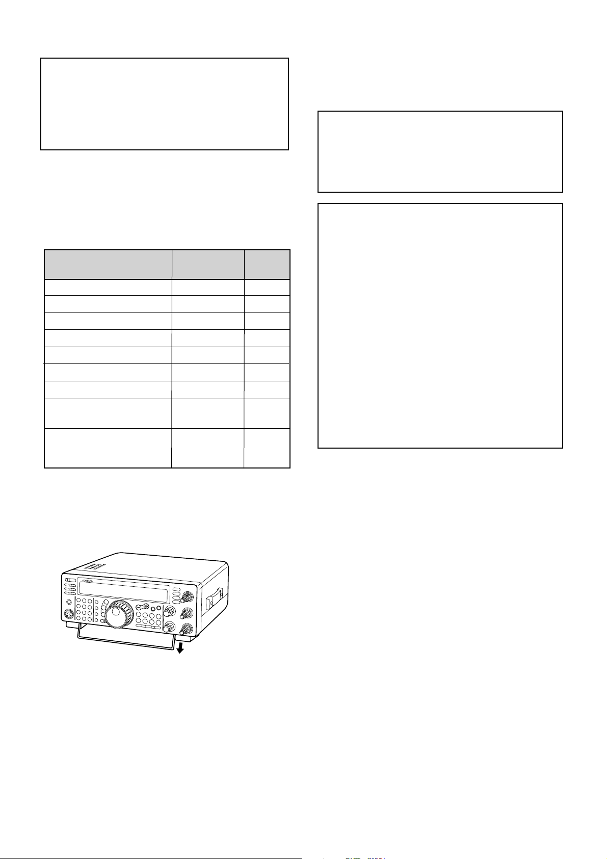
This transceiver is equipped with a bail on the bottom so
that you can angle the transceiver. Pull the bail forward
to the limit as shown:
Page 3

THANK YOU
Instruction What to Do
Press and release KEY.
Press and hold KEY1 down,
then press KEY2. If there are
more than two keys, press and
hold down each key in turn
until the final key has been
pressed.
Press KEY1 momentarily,
release KEY1, then press
KEY2.
With the transceiver power
OFF, press and hold KEY,
then switch ON the transceiver
power by pressing the
[ ] (POWER) switch.
Press [KEY].
Press
[KEY1]+[KEY2].
Press
[KEY1], [KEY2].
Press
[KEY]+[ ].
Thank you for choosing the KENWOOD TS-570 series.
This Intelligent Digital Enhanced Communications
System was developed by a team of engineers
determined to continue the tradition of excellence and
innovation in KENWOOD HF transceivers.
This transceiver includes a 16-bit Digital Signal
Processing (DSP) unit to process audio frequencies. By
taking maximum advantage of DSP technology the
transceiver gives you enhanced interference reduction
capabilities and improves the quality of audio that you
transmit. You will find the differences when you fight
QRM and QRN in the new solar cycle. As you learn
how to use this transceiver, you also will find
KENWOOD is pursuing “user friendliness”. For
example, each time you change the Menu No. in Menu
mode, you will see, on the display, scrolling messages
that tell what you are selecting.
Though user friendly, this transceiver is technically
sophisticated and some features may be new to you.
Consider this manual to be a personal tutorial from the
designers. Allow the manual to guide you through the
learning process now, then act as a reference in the
coming years.
WRITING CONVENTIONS FOLLOWED
The writing conventions described below have been
followed to simplify instructions and avoid unnecessary
repetition. This format is less confusing for the reader.
Reviewing the following information now will reduce
your learning period. That means less time will be
spent reading this manual; more time will be available
for operating.
Furthermore, a system of advisories is used as follows:
WARNING!
CAUTION:
Note:
➡ Possibility of personal injury
➡ Possibility of equipment damage
➡ Important information or operating tip
FEATURES
Taking full advantage of DSP technology, this
transceiver
• Provides high performance receive filters.
• Enhances the Beat Cancel and Noise Reduction
tools.
• Allows total customization of transmitted audio
through the use of functions such as the Transmit
Equalizer.
• Enables Automatic Zero-beating for CW operation.
To pursue user friendliness, this transceiver
• When in Menu mode, scrolls messages to tell you
what you are selecting.
• Allows you to quickly and easily save the current
transceiver settings in Quick memory.
• Is equipped with a large, easy to read LCD display.
Note:
Basic procedures are numbered sequentially to guide you
step-by-step. Additional information pertaining to a step, but not
essential to complete the procedure, is provided in bulleted form
following many steps.
i
Page 4

CONTENTS
PRECAUTIONS IV
CHAPTER 1 INSTALLATION 1
ANTENNA CONNECTION ....................................... 1
GROUND CONNECTION ........................................ 2
LIGHTNING PROTECTION ..................................... 2
DC POWER SUPPLY CONNECTION ...................... 2
REPLACING FUSES ........................................... 2
ACCESSORY CONNECTIONS ............................... 3
FRONT PANEL .................................................... 3
Headphones (PHONES) ................................. 3
Microphone (MIC) ........................................... 3
REAR PANEL ...................................................... 3
External Speaker (EXT SP) ............................ 3
Keys and Keyboards for
CW Operation (PADDLE and KEY) ................. 3
CHAPTER 2 YOUR FIRST QSO 4
RECEIVING ............................................................. 4
TRANSMITTING ...................................................... 5
CHAPTER 3 GETTING ACQUAINTED 6
FRONT PANEL ........................................................ 6
MICROPHONE ........................................................ 9
REAR PANEL ........................................................ 10
DISPLAY ............................................................... 11
CHAPTER 4 OPERATING BASICS 13
SWITCHING POWER ON/OFF ............................. 13
ADJUSTING VOLUME .......................................... 13
AUDIO FREQUENCY (AF) GAIN....................... 13
RADIO FREQUENCY (RF) GAIN ...................... 13
SELECTING VFO A OR VFO B ............................. 13
SELECTING A BAND ............................................ 13
SELECTING A MODE ........................................... 14
ADJUSTING SQUELCH ........................................ 14
SELECTING A FREQUENCY ................................ 14
FRONT PANEL METER ........................................ 14
TRANSMITTING .................................................... 15
SELECTING TRANSMIT POWER ..................... 15
MICROPHONE GAIN ........................................ 15
CHAPTER 5 MENU SETUP 16
WHAT IS A MENU? ............................................... 16
MENU A/ MENU B ................................................. 16
MENU ACCESS .................................................... 16
MENU CONFIGURATION ..................................... 17
CROSS REFERENCE FOR
MENU FUNCTIONS .............................................. 19
CHAPTER 6 BASIC COMMUNICATING 20
SSB TRANSMISSION ........................................... 20
CW TRANSMISSION ............................................ 21
AUTO ZERO-BEAT ........................................... 21
TX SIDETONE/ RX PITCH FREQUENCY ......... 21
FM TRANSMISSION ............................................. 22
TX DEVIATION SELECTION ............................. 22
AM TRANSMISSION ............................................. 22
CHAPTER 7 SPECIALIZED COMMUNICATING 23
SPLIT-FREQUENCY OPERATION ........................ 23
TF-SET (TRANSMIT FREQUENCY SET) .......... 23
FM REPEATER OPERATION ................................ 24
SELECTING SUBTONE FREQUENCY ............. 25
CONTINUOUS OR BURST SUBTONES? ......... 25
FM CTCSS OPERATION ....................................... 25
DIGITAL OPERATION ........................................... 26
RTTY (FREQUENCY SHIFT KEYING) .............. 26
AMTOR/ PACKET/ PACTOR/ G-TORTM/ CLOVER . 27
SLOW SCAN TV/ FACSIMILE ............................... 28
SATELLITE OPERATION ...................................... 28
CHAPTER 8 COMMUNICATING AIDS 29
RECEIVING ........................................................... 29
SELECTING YOUR FREQUENCY .................... 29
Direct Frequency Entry ................................. 29
Using 1 MHz Steps ....................................... 29
Quick Changes ............................................. 29
Fine Tuning................................................... 29
Equalizing VFO Frequencies (A=B) .............. 30
RIT (RECEIVE INCREMENTAL TUNING) ......... 30
AGC (AUTOMATIC GAIN CONTROL) ............... 30
RX EQUALIZER ................................................ 30
TRANSMITTING .................................................... 31
VOX (VOICE-OPERATED TRANSMIT) ............. 31
Microphone Input Level ................................. 31
Delay Time ................................................... 31
SPEECH PROCESSOR .................................... 32
XIT (TRANSMIT INCREMENTAL TUNING) ....... 32
CUSTOMIZING TRANSMIT SIGNAL
CHARACTERISTICS ......................................... 33
Changing Transmit
Bandwidth (SSB/AM) .................................... 33
Equalizing Transmit Audio (SSB/FM/AM) ...... 33
MONITORING TRANSMITTED SIGNALS ......... 33
TRANSMIT INHIBIT ........................................... 33
CHANGING FREQUENCY WHILE
TRANSMITTING ................................................ 33
CW BREAK-IN ....................................................... 34
USING SEMI BREAK-IN OR
FULL BREAK-IN ................................................ 34
ELECTRONIC KEYER .......................................... 34
CHANGING KEYING SPEED ............................ 34
AUTO WEIGHTING ........................................... 34
Reversible Auto Weighting ............................ 34
CHANGING LOCKED-WEIGHT ........................ 35
BUG KEY FUNCTION ....................................... 35
CW MESSAGE MEMORY ................................. 35
Storing CW Messages .................................. 35
Checking CW Messages without Transmitting35
Transmitting CW Messages .......................... 35
CHAPTER 9 REJECTING INTERFERENCE 36
IF FILTER .............................................................. 36
CHANGING IF FILTER BANDWIDTH ................ 36
IF SHIFT ............................................................ 36
NOISE BLANKER .................................................. 36
ii
Page 5

ATTENUATOR ....................................................... 37
PREAMPLIFIER .................................................... 37
DSP TOOLS .......................................................... 37
CHANGING RECEIVE BANDWIDTH ................ 37
SSB/ FM/ AM Modes .................................... 37
CW/ FSK Modes ........................................... 38
BEAT CANCEL .................................................. 38
NOISE REDUCTION ......................................... 38
Changing NR1 Performance ......................... 38
Setting NR2 Time Constant........................... 38
CHAPTER 10 MEMORY FEATURES 39
MICROPROCESSOR MEMORY BACKUP............ 39
CONVENTIONAL MEMORY.................................. 39
STORING DATA IN MEMORY ........................... 39
Simplex Channels ......................................... 39
Split-Frequency Channels ............................. 40
MEMORY RECALL AND SCROLL .................... 40
Memory Recall .............................................. 40
Memory Scroll ............................................... 41
Temporary Frequency Changes .................... 41
Memory-VFO Split Operation ........................ 41
MEMORY TRANSFER ...................................... 42
Memory ➡ VFO Transfer ............................. 42
Channel ➡ Channel Transfer ....................... 42
STORING FREQUENCY RANGES ................... 43
Confirming Start/End Frequencies ................ 43
Programmable VFO ...................................... 43
ERASING MEMORY CHANNELS ..................... 43
Full Reset ..................................................... 43
Memory Channel Lockout ............................. 44
QUICK MEMORY .................................................. 44
STORING INTO QUICK MEMORY .................... 44
RECALLING QUICK MEMORY ......................... 45
TEMPORARY FREQUENCY CHANGES .......... 45
QUICK MEMORY ➡ VFO TRANSFER .............. 45
CHAPTER 11 SCAN 46
PROGRAM SCAN ................................................. 46
SCAN HOLD ..................................................... 46
MEMORY SCAN ................................................... 47
ALL-CHANNEL SCAN ....................................... 47
GROUP SCAN .................................................. 47
CHAPTER 12 OPERATOR CONVENIENCES 48
MICROPROCESSOR RESET ............................... 48
INITIAL SETTINGS ............................................ 48
PARTIAL RESET ............................................... 48
FULL RESET ..................................................... 48
SWITCHING ANT 1/ ANT 2.................................... 48
FREQUENCY LOCK FUNCTION .......................... 48
BEEP FUNCTION .................................................. 49
DISPLAY DIMMER ................................................ 49
PROGRAM FUNCTION BUTTON ......................... 49
QUICK DATA TRANSFER ..................................... 50
SETTING UP ..................................................... 50
Equipment Needed ....................................... 50
Connections ................................................. 50
USING QUICK TRANSFER ............................... 50
Transferring Data .......................................... 50
Receiving Data ............................................. 50
COMPUTER CONTROL ........................................ 51
SETTING UP ..................................................... 51
Equipment Needed ....................................... 51
Connections ................................................. 51
COMMUNICATION PARAMETERS ................... 51
USING A TRANSVERTER ..................................... 51
AUTOMATIC ANTENNA TUNER ........................... 52
PRESETTING ................................................... 52
DRU-3A DIGITAL RECORDING UNIT
(OPTIONAL) .......................................................... 53
RECORDING MESSAGES ................................ 53
MESSAGE PLAYBACK ..................................... 53
Checking Messages ..................................... 53
Sending Messages ....................................... 54
Changing Inter-message Interval .................. 54
Changing Volume ......................................... 54
VS-3 VOICE SYNTHESIZER (OPTIONAL) ............ 55
CHAPTER 13 OPTIONAL ACCESSORIES 56
CHAPTER 14 INSTALLING OPTIONS 57
REMOVING THE BOTTOM CASE ........................ 57
DRU-3A DIGITAL RECORDING UNIT ................... 57
VS-3 VOICE SYNTHESIZER UNIT ........................ 58
YK-88C-1/ YK-88CN-1/ YK-88SN-1 FILTERS ........ 58
SO-2 TEMPERATURE-COMPENSATED CRYSTAL
OSCILLATOR (TCXO) ........................................... 59
CHAPTER 15 CONNECTING PERIPHERAL EQUIPMENT 60
COMPUTER .......................................................... 60
COMPATIBLE TRANSCEIVER .............................. 60
RTTY EQUIPMENT ............................................... 61
LINEAR AMPLIFIER .............................................. 61
ANTENNA TUNER ................................................ 61
MCP AND TNC ...................................................... 62
CHAPTER 16 MAINTENANCE 63
GENERAL INFORMATION .................................... 63
SERVICE ........................................................... 63
SERVICE NOTE ................................................ 63
CLEANING ........................................................ 63
INTERNAL ADJUSTMENTS .................................. 64
REFERENCE FREQUENCY CALIBRATION ..... 64
ACCESSING THE INTERNAL FUSE................. 64
TROUBLESHOOTING ........................................... 65
SPECIFICATIONS 68
APPENDIX: COM CONNECTOR PROTOCOL 70
INDEX 82
iii
Page 6
PRECAUTIONS
Please read all safety and operating instructions before
using this transceiver. For best results, be aware of all
warnings on the transceiver and follow these operating
instructions. Retain these safety and operating
instructions for future reference.
1 Power Source
Connect this transceiver only to the power source
described in the operating instructions or as marked
on the transceiver itself.
2 Power Cable Protection
Route all power cables safely. Ensure the power
cables can neither be walked upon nor pinched by
items placed near or against the cables. Pay
particular attention to locations near AC receptacles,
AC outlet strips and points of entry to the transceiver.
3 Electrical Shocks
Take care not to drop objects or spill liquids into the
transceiver through enclosure openings. Metal
objects, such as hairpins or needles, inserted into
the transceiver may contact voltages resulting in
serious electrical shocks. Never permit children to
insert any objects into this transceiver.
4 Grounding and Polarization
Do not attempt to defeat methods used for
grounding and electrical polarization in the
transceiver, particularly involving the input power
cable.
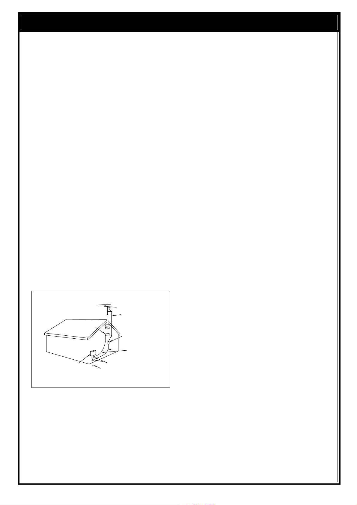
5 Outdoor Antenna Grounding
Adequately ground all outdoor antennas used with
this transceiver using approved methods.
Grounding helps protect against voltage surges
caused by lightning. It also reduces the chance of a
build-up of static charges.
EXAMPLE OF ANTENNA GROUNDING
ANTENNA
LEAD IN
GROUND
CLAMP
ELECTRIC SERVICE
EQUIPMENT
POWER SERVICE
GROUNDING ELECTRODE
SYSTEM
WIRE
ANTENNA
DISCHARGE UNIT
GROUNDING
CONDUCTORS
GROUND CLAMPS
6 Power Lines
Minimum recommended distance for an outdoor
antenna from power lines is one and one-half times
the vertical height of the associated antenna support
structure. This distance allows adequate clearance
from the power lines if the support structure should
fail for any reason.
7Ventilation
Locate the transceiver so as not to interfere with its
ventilation. Do not place books or other equipment
on the transceiver that may impede the free
movement of air. Allow a minimum of 4 inches
(10cm) between the rear of the transceiver and the
wall or operating desk shelf.
8Water and Moisture
Do not use the transceiver near water or sources of
moisture. For example, avoid use near bathtubs,
sinks, swimming pools, and in damp basements and
attics.
9 Abnormal Odors
The presence of an unusual odor or smoke is often a
sign of trouble. Immediately turn the power OFF and
remove the power cable. Contact a dealer or the
nearest Service Center for advice.
10 Heat
Locate the transceiver away from heat sources such
as radiators, stoves, amplifiers or other devices that
produce substantial amounts of heat.
11 Cleaning
Do not use volatile solvents such as alcohol, paint
thinner, gasoline or benzene to clean the cabinet.
Use a clean cloth with warm water or a mild
detergent.
12 Periods of Inactivity
Disconnect the input power cable from the power
source when the transceiver is not used for long
periods of time.
13 Servicing
Remove the transceiver’s enclosure only to do
accessory installations described by this manual or
accessory manuals. Follow provided instructions
carefully to avoid electrical shocks. If unfamiliar with
this type of work, seek assistance from an
experienced individual, or have a professional
technician do the task.
14 Damage Requiring Service
Enlist the services of qualified personnel in the
following cases:
a) The power supply or plug is damaged.
b) Objects have fallen or liquid has spilled into the
transceiver.
c) The transceiver has been exposed to rain.
d) The transceiver is operating abnormally or
performance has degraded seriously.
e) The transceiver has been dropped or the
enclosure damaged.
iv
Page 7
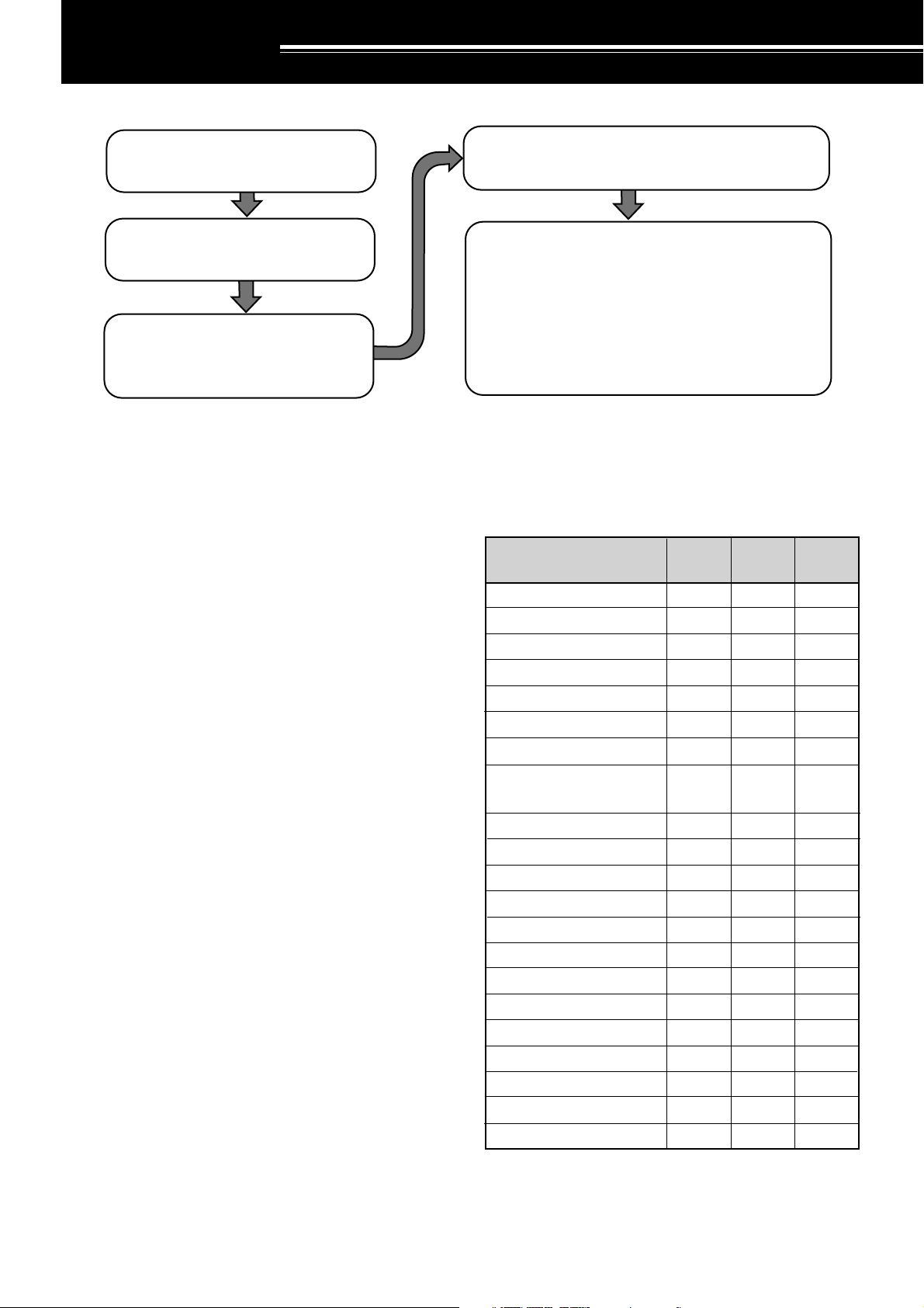
INSTALLATION
|nstall and connect an antenna system
{page 1}.
Install a ground system that satisfies DC
and RF grounding requirements {page 2}.
Install lightning protection to protect the
antenna system, your personal safety,
and your property {page 2}.
ANTENNA CONNECTION
The type of the antenna system, consisting of the
antenna, ground, and feed line, will greatly affect the
successful performance of the transceiver. Use a
properly adjusted 50 Ω antenna of good quality to let
your transceiver perform at its best. Use a good-quality
50 Ω coaxial cable and a first-quality connector for the
connection. Match the impedance of the coaxial cable
and antenna so that the SWR is 1.5:1 or less. All
connections must be clean and tight.
While the transceiver’s protection circuit will activate if
the SWR is greater than 2.5:1, do not rely on protection
to compensate for a poorly functioning antenna system.
High SWR will cause the transmit output to drop, and
may lead to radio frequency interference to consumer
products such as stereo receivers and televisions. You
may even interfere with your own transceiver. Reports
that your signal is garbled or distorted, especially at
peak modulation, may indicate that your antenna
system is not efficiently radiating the transceiver’s
power. If you feel a tingle from the transceiver’s cabinet
or the microphone’s metal fittings when you modulate,
you can be certain that, at the least, your coax
connector is loose at the rear of the radio and, at the
worst, your antenna system is not efficiently radiating
power.
Connect your antenna feed line to ANT1. If you are
using two antennas, connect the second antenna to
ANT2.
CAUTION:
◆
TRANSMITTING WITHOUT FIRST CONNECTING AN
ANTENNA OR OTHER MATCHED LOAD MAY DAMAGE THE
TRANSCEIVER. ALWAYS CONNECT THE ANTENNA TO THE
TRANSCEIVER BEFORE TRANSMITTING.
◆
USE A LIGHTNING ARRESTOR TO PREVENT FIRE,
ELECTRIC SHOCK, OR DAMAGE TO THE TRANSCEIVER.
Install and connect a DC power supply {page 2}.
Connect all accessories to the transceiver {pages 3, 60}.
Accessories include the following:
• Microphone
• Antenna Tuner
• CW Key
• Computer
• TNC/ Multimode Communications
Processor
• Headphones
• External Speaker
• RTTY Equipment
• Linear Amplifier
APPROX. LOSS (dB) PER 30 METERS (100 FEET) OF
CORRECTLY MATCHED 50 Ω LINE
• Use only as a general guide. Specifications may vary
between cable manufacturers.
Transmission Line
RG-174, -174A
RG-58A, -58C
3D-2V
RG-58, -58B
RG-58 Foam
RG-8X
5D-2V
RG-8, -8A, -9, -9A, -9B,
3.5 MHz
2.3
0.75
0.80
0.65
0.70
0.50
0.45
0.38
14 MHz 30 MHz
4.3
1.6
1.5
1.5
1.4
1.0
0.93
0.80
6.4
2.6
2.3
2.3
2.1
2.0
1.4
1.2
-213, -214, -215
5D-FB
RG-8 Foam
8D-2V
10D-2V
9913
8D-FB
10D-FB
12D-FB
RG-17, -17A
1/2" Hardline
20D-2V
3/4" Hardline
7/8" Hardline
N/A
0.29
0.29
0.24
0.24
N/A
N/A
N/A
0.13
0.12
< 0.10
< 0.10
< 0.10
0.80
0.60
0.60
0.50
0.48
0.48
0.37
0.33
0.29
0.26
0.25
0.21
0.16
1.0
0.90
0.90
0.72
0.70
0.68
0.54
0.45
0.48
0.40
0.39
0.32
0.26
N/A: Not available
1
Page 8
1 INSTALLATION
DC power supply
TS-570
Black
Red
Fuse holders
DC 13.8 V
GROUND CONNECTION
At the minimum, a good DC ground is required to
prevent such dangers as electric shock. For superior
communications results, a good RF ground is required,
against which the antenna system can operate. Both of
these conditions can be met by providing a good earth
ground for your station. Bury one or more ground rods,
or a large copper plate under the ground, and connect
this to the transceiver GND terminal. Use heavy gauge
wire or a copper strap, cut as short as possible, for this
connection. Just as for antenna work, all connections
must be clean and tight.
LIGHTNING PROTECTION
Consider carefully how to protect your equipment and
your home from lightning. Even in areas where
lightning storms are less common, there are usually a
limited number of storms each year. Take the time to
study the best way to protect your installation from the
effects of lightning by consulting reference material on
the subject.
The installation of a lightning arrestor is a start, but there
is more that you can do. For example, terminate your
antenna system transmission lines at an entry panel
that you install outside your home. Ground this entry
panel to a good outside ground, and then connect
appropriate feed lines between the entry panel and your
transceiver. When a lightning storm occurs, you can
ensure added protection by disconnecting the feed lines
from your transceiver.
CAUTION:
CLEARLY DANGEROUS), AN ELECTRICAL CONDUIT (WHICH
HAS THE WHOLE HOUSE WIRING ATTACHED AND MAY ACT
LIKE AN ANTENNA), OR A PLASTIC WATER PIPE FOR A
GROUND.
DO NOT ATTEMPT TO USE A GAS PIPE (WHICH IS
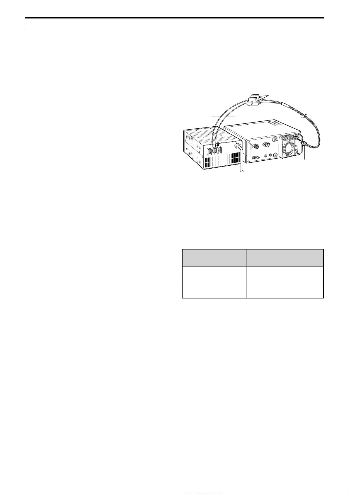
DC POWER SUPPLY CONNECTION
In order to use this transceiver, you will need a separate
13.8 V DC power supply that must be purchased
separately. DO NOT directly connect the transceiver to
an AC outlet! Use the supplied DC power cable to
connect the transceiver to a regulated power supply. Do
not substitute a cable with smaller gauge wires. The
current capacity of your power supply must be 20.5 A
peak or more.
CAUTION:
◆
BEFORE CONNECTING THE DC POWER SUPPLY TO THE
TRANSCEIVER, BE SURE TO SWITCH THE TRANSCEIVER
AND THE DC POWER SUPPLY OFF.
◆
DO NOT PLUG THE DC POWER SUPPLY INTO AN AC
OUTLET UNTIL YOU MAKE ALL CONNECTIONS.
First connect the DC power cable to the regulated DC
power supply and check that polarities are correct
(Red: positive, Black: negative). Then connect the
connectorized end of the DC power cable to the
DC13.8V power connector on the transceiver rear
panel. Press the DC power cable connector firmly into
the connector on the transceiver until the locking tab
clicks.
REPLACING FUSES
If the fuse blows, determine the cause then correct the
problem. After the problem is resolved, only then
replace the fuse. If newly installed fuses continue to
blow, disconnect the power plug and contact your
dealer or nearest Service Center for assistance.
Fuse Location
TS-570
Supplied Accessory
Cable
CAUTION:
INVESTIGATING AND CORRECTING THE CAUSE OF THE
FAILED FUSE. ALWAYS REPLACE A BLOWN FUSE BY A NEW
FUSE WITH THE SPECIFIED RATINGS.
REPLACE BLOWN FUSES ONLY AFTER
Fuse Current Rating
4 A
(For an external antenna tuner)
25 A
2
Page 9
ACCESSORY CONNECTIONS
FRONT PANEL
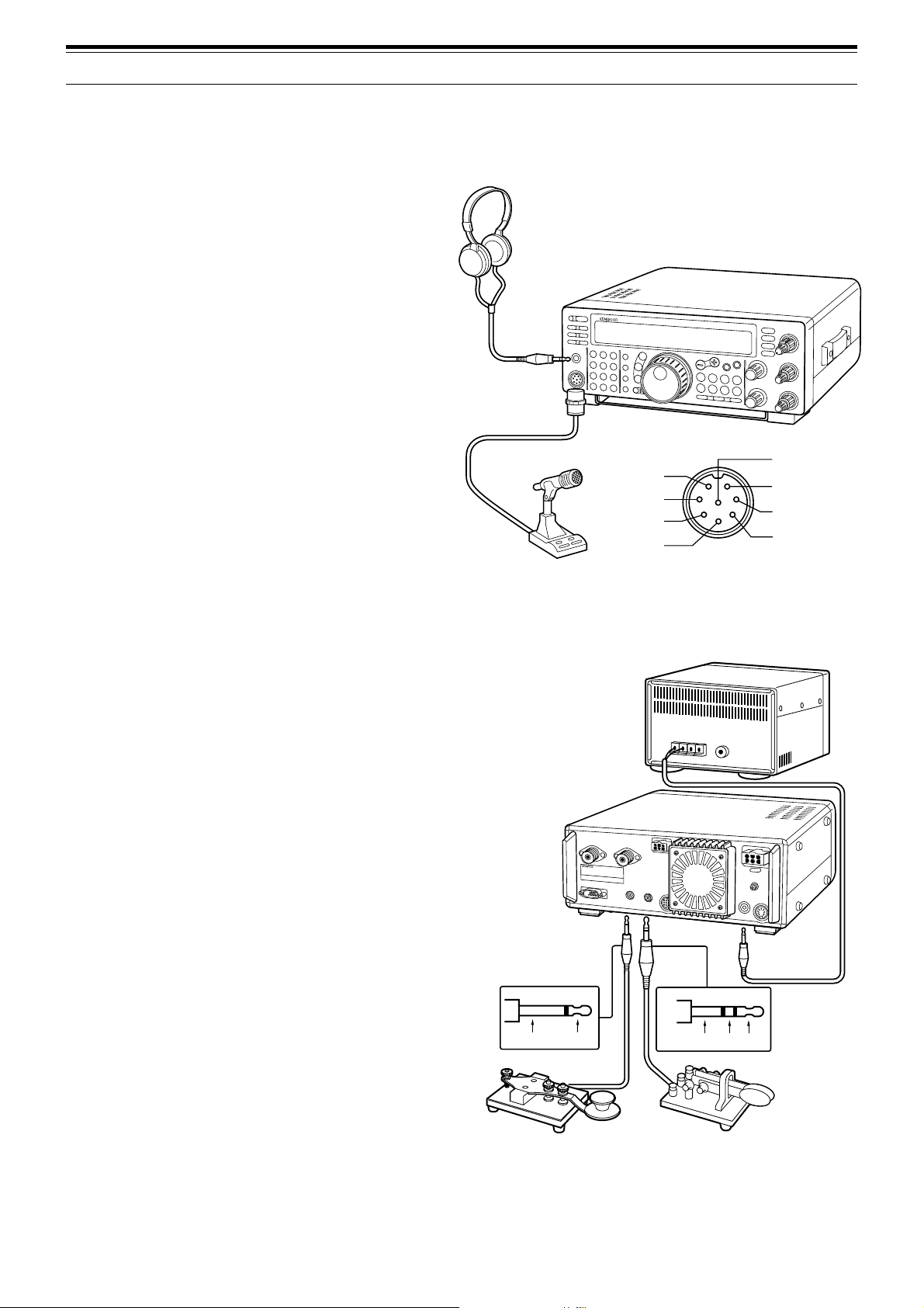
■ Headphones (PHONES)
Use headphones having 4 to 32 Ω impedance. You
can also use stereo headphones. When
headphones are used, no sound is heard from the
internal (or optional external) speaker. Use a 6.0 mm
(1/4") diameter, 2-conductor (mono) or 3-conductor
(stereo) plug.
■ Microphone (MIC)
To communicate in the voice modes, connect to the
MIC connector a microphone having an impedance
between 250 Ω and 600 Ω. Insert the connector
from your microphone fully, then screw the retaining
ring clockwise until snug. Compatible microphones
include the MC-43S, MC-47, MC-60A, MC-80,
MC-85, and MC-90. Do not use the MC-44,
MC-44DM, MC-45, MC-45E, MC-45DM,
MC-45DME, MC-52DM, or MC-53DM microphone.
REAR PANEL
Headphones
Microphone
MICq
PTTw
DOWNe
UPr
1 INSTALLATION
TS-570
iGND(STBY)
uGND(MIC)
yNC
t8 V(10 mA max)
MIC connector (Front view)
■ External Speaker (EXT SP)
Ensure any external speaker used has an
impedance of 8 Ω. Use a 3.5 mm (1/8") diameter,
2-conductor (mono) plug. When an external speaker
is used, no sound is heard from the internal speaker.
WARNING!
JACK. THE HIGH AUDIO OUTPUT AT THIS JACK COULD
DAMAGE YOUR HEARING.
DO NOT CONNECT HEADPHONES TO THIS
■ Keys and Keyboards for CW Operation
(PADDLE and KEY)
For CW operation using the internal electronic keyer,
connect a keyer paddle to the PADDLE jack. For
CW operation without using the internal electronic
keyer, connect a straight key, semi-automatic key
(bug), electronic keyer, or the CW keyed output from
a Multimode Communications Processor (MCP) to
the KEY jack. The jacks mate with a 6.0 mm (1/4")
3-conductor plug and a 3.5 mm (1/8") 2-conductor
plug respectively. External electronic keyers or
MCPs must use positive keying to be compatible
with this transceiver. Use a shielded cable between
the key and the transceiver.
Note:
Due to the full-featured functionality of the internal
electronic keyer, you may decide it’s unnecessary to connect
both a paddle and another type of key unless you specifically
want to use a keyboard for CW. It’s recommended that you
become familiar with the internal keyer by reading
“ELECTRONIC KEYER” {page 34} before making your decision.
External speaker
TS-570
Ground +
Ground Dash
Dot
• Straight key
• Bug
• Electronic keyer
• MCP CW output
• Paddle
3
Page 10
2 YOUR FIRST QSO
Since you’ve now installed the TS-570, why not try it? The instructions below are abbreviated. They are intended
only to act as a quick introduction. If you encounter problems or there’s something you don’t understand, you can
read about the subject in more detail later.
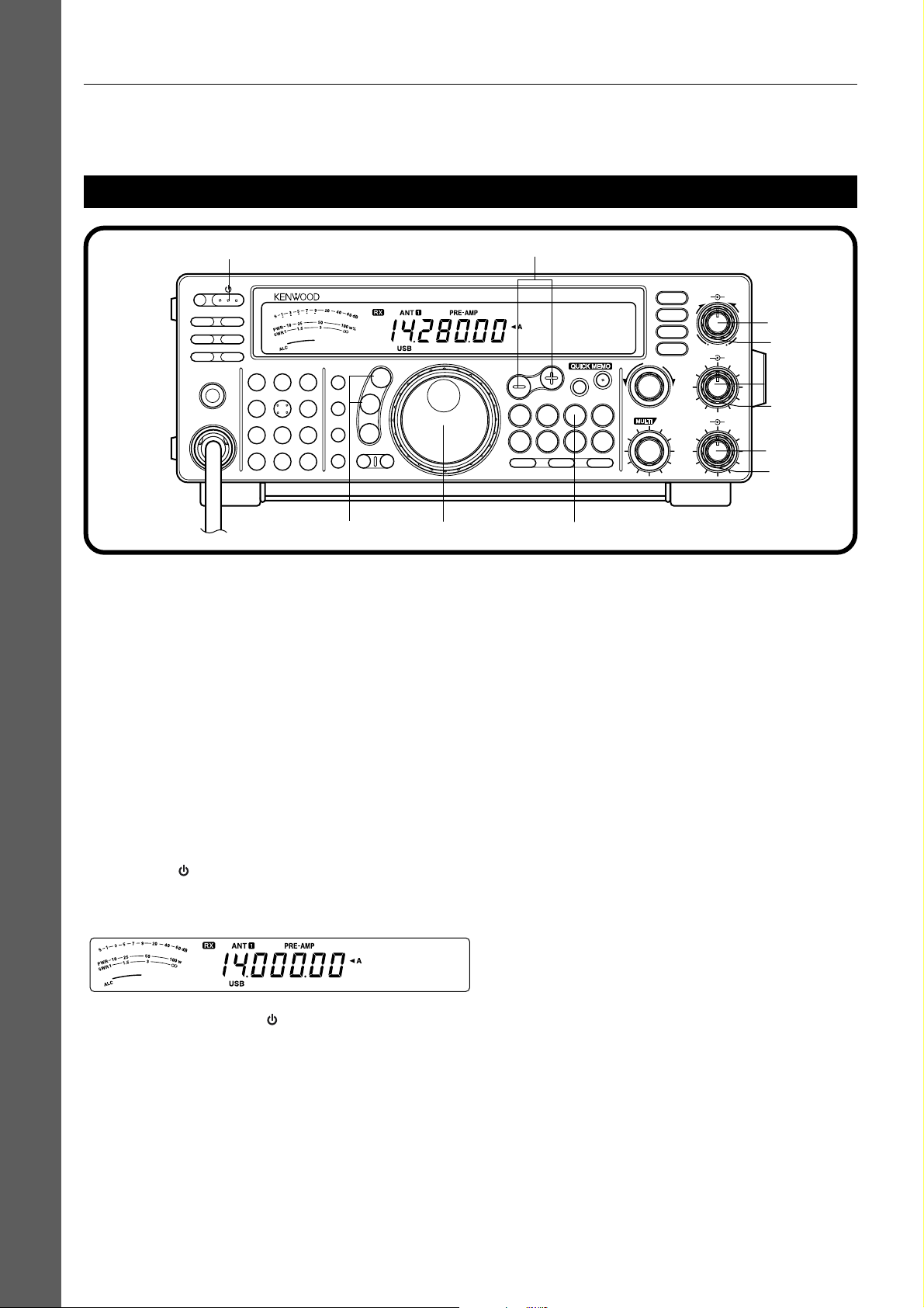
RECEIVING
tw
PF
ATT PRE-AMP
VOX PROC
AT TUNE
SEND
PHONES
MIC
CH22CH3
CH1
1
ANT4REC5FINE
NB7AGC/TONE8REV
F.LOCK
CLR
3
6
9
ENT
0
HF TRANSCEIVER TS-570D
MIC
LSB
USB
PWR
CW
FSK
KEY
FM
AM
DELAY MENU 1MHz
y
Note:
Only those buttons and controls required to briefly try the
transceiver are explained in this section.
q Set the following as specified:
• AF control: Fully counterclockwise
• RF control: Fully clockwise
• DSP SLOPE (HIGH) control:
Fully clockwise
• DSP SLOPE (LOW) control:
Fully counterclockwise
• IF SHIFT control: Center
• SQL control: Fully counterclockwise
w Switch ON the DC power supply, then press and
hold the [ ] (POWER) switch briefly.
• The transceiver switches ON. Indicators and
frequency digits should appear on the display.
u
DSP SLOPE
HIGH
LOW
T
U
C
W
O
L
AF RF
46
28
010
IF SHIFT SQL
46
28
010
q
q
qr
q
q
q
UP
DOWN
SPLIT
TF-SET
M/V
A=B
SCAN M>VFO M.IN
A/B
CLEAR
N.R.
B.C.
CW TUNE
FILTER
MR
M.IN
RIT
XIT
RIT/XIT
+–
CH
e
e VFO A should already be selected for receiving
and transmitting, and you should see “tA” on the
display. If not, press the [A/B] button.
r Increase the AF control slowly clockwise until you
hear a suitable level of background noise.
t Select an Amateur band by pressing the [UP] or
[DOWN] button.
y Select an operating mode by pressing the
[LSB/USB] or [CW/FSK] button.
• Press the same button again to toggle to the
second function on the button. For example,
repeatedly pressing the [LSB/USB] button
switches between LSB and USB modes.
u Turn the Tuning control to tune in a station.
• If no stations are heard but you have an
antenna connected, possibly the wrong
antenna connector is selected. Pressing the
[ANT] button toggles between the Antenna 1
and the Antenna 2 connectors.
• Note that pressing [ ] (POWER) for more
than approximately 2 seconds switches the
transceiver power OFF.
YOUR FIRST QSO
4
Page 11
ro
2 YOUR FIRST QSO
YOUR FIRST QSO
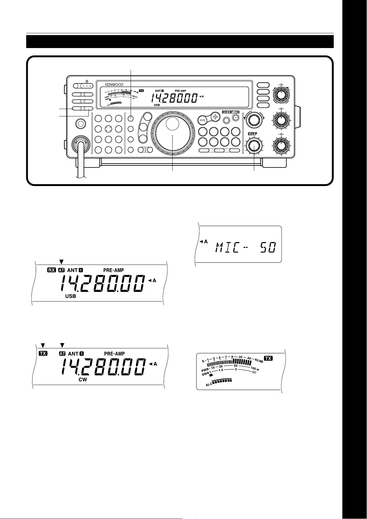
TRANSMITTING
ti
we
PF
ATT PRE-AMP
VOX PROC
SEND
AT TUNE
PHONES
MIC
CH1
CH22CH3
1
ANT4REC5FINE
NB7AGC/TONE8REV
F.LOCK
CLR
3
6
9
ENT
0
HF TRANSCEIVER TS-570D
MIC
LSB
USB
PWR
CW
FSK
KEY
FM
AM
DELAY MENU 1MHz
After tuning in a few stations as explained in the
previous section “RECEIVING”, try making a contact.
q Assuming you are already on the correct band
with the correct mode selected (steps 1~7 in
“RECEIVING”), use the Tuning control to tune in
a station or to select an unused frequency.
w Momentarily press the [AT TUNE] button.
•“AT” appears.
q
DSP SLOPE
HIGH
LOW
T
U
C
W
O
L
AF RF
46
28
010
IF SHIFT SQL
46
28
010
UP
DOWN
TF-SET
SPLIT
M/V
A=B
SCAN M>VFO M.IN
A/B
CLEAR
N.R.
B.C.
CW TUNE
FILTER
MR
M.IN
RIT
XIT
RIT/XIT
+–
CH
u
r SSB: Press the [MIC] button to activate the
Microphone Gain Setting function.
• “MIC-50” appears.
e Press and hold the [AT TUNE] button to allow the
built-in antenna tuner to function.
•“AT” blinks and “TX” appears.
•Tuning should be completed in less than
approximately 20 seconds. “AT” stops blinking
and “TX” disappears.
• If tuning is not completed in approximately 20
seconds, error beeps sound. Press
[ATTUNE] to stop the error beeps and to quit
tuning. Check your antenna system before
continuing.
Note:
Tuning will automatically turn off after approximately
60 seconds. In addition, “AT” will disappear and the error beeps
will stop.
CW: Skip this step.
t Press the [SEND] button.
• “TX” appears.
y Begin speaking into the microphone or sending
CW with your key.
u SSB: While speaking into the microphone, adjust
the MULTI/CH control so that the ALC meter
reflects according to your voice level.
CW: Skip this step.
i Press the [SEND] button again when you want to
return to receive mode.
o Press the [MIC] button again to quit the
Microphone Gain Setting function.
This completes your introduction to the TS-570, but
there is a great deal more to know. “OPERATING
BASICS” {page 13} and following chapters explain all
functions of the transceiver starting with the most
basic, commonly-used functions.
5
Page 12
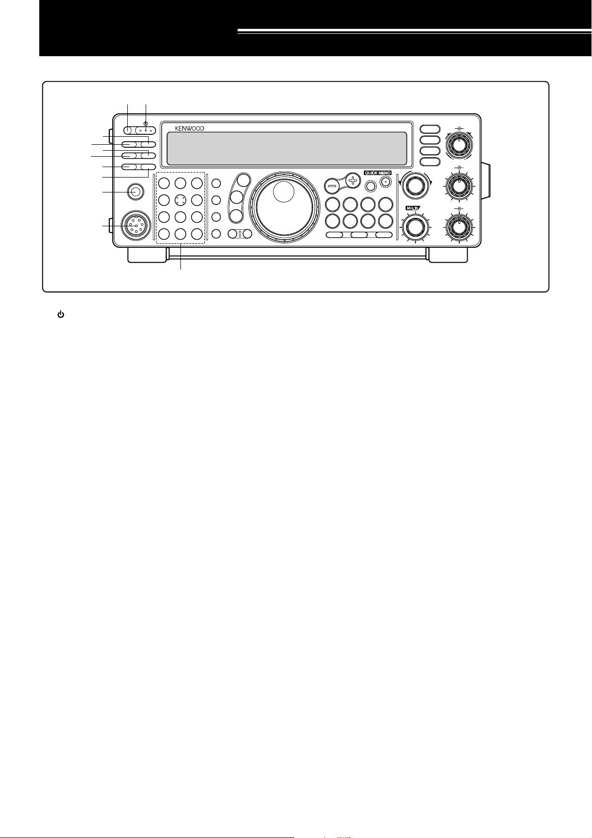
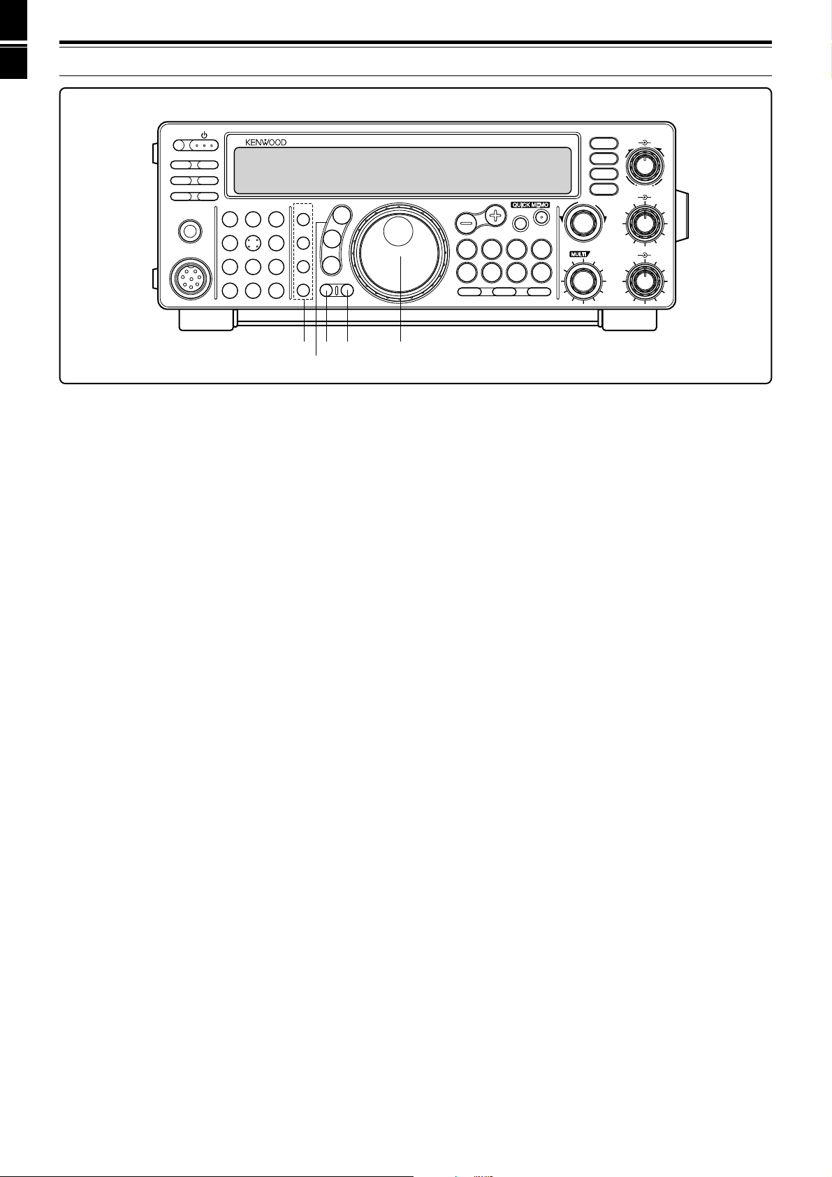
GETTING ACQUAINTED
FRONT PANEL
q
w
r
y
e
t
i
u
o
!0
PF
ATT PRE-AMP
VOX PROC
AT TUNE
SEND
PHONES
MIC
CH22CH3
CH1
1
ANT4REC5FINE
NB7AGC/TONE8REV
F.LOCK
CLR
3
6
9
ENT
0
HF TRANSCEIVER TS-570D
MIC
LSB
USB
PWR
CW
FSK
KEY
FM
AM
DELAY MENU 1MHz
!1
qq
q (POWER) switch
qq
Press and hold down briefly to switch ON the
transceiver power. Press again to switch OFF the
power {page 13}.
ww
w PF button
ww
A function can be assigned by the user to this
Programmable Function button {page 49}. The default
function is Voice 1 {page 55}.
ee
e PRE-AMP button
ee
Press to switch ON or OFF the receive preamplifier
{page 37}.
rr
r AT T button
rr
Press to switch ON or OFF the receive attenuator
{page37}.
tt
t PROC button
tt
Press to switch ON or OFF the Speech Processor for
transmitting {page 32}.
DSP SLOPE
HIGH
LOW
T
U
C
W
O
L
AF RF
46
28
010
IF SHIFT SQL
46
28
010
UP
DOWN
SPLIT
M/V
SCAN M>VFO M.IN
oo
o PHONES jack
oo
TF-SET
A=B
MR
A/B
CLEAR
M.IN
RIT
XIT
N.R.
B.C.
CW TUNE
FILTER
RIT/XIT
+–
CH
Connect headphones to this jack. Inserting a plug into
the jack automatically mutes the audio from the speaker
{page 3}.
!0!0
!0 MIC connector
!0!0
Connect a compatible microphone, then snugly screw
down the connector locking ring {page 3}.
!1!1
!1 Multi-purpose keypad
!1!1
Consists of 10 buttons that are used for inputting
numeric data. Also used for the following functions.
• CH 1, CH 2, CH 3 buttons
Press to select functions associated with the internal
electronic keyer {page 34} and the DRU-3A Digital
Recording Unit {page 53} .
• ANT button
Press to select either Antenna 1 or Antenna 2 that
are connected to their respective antenna
connectors on the rear panel {pages 1, 48}.
• REC button
yy
y VOX button
yy
In voice modes, press to switch ON or OFF the VoiceOperated Transmit function {page 31} or, in CW mode,
to switch ON or OFF the Break-in function {page 34}.
uu
u AT TUNE button
uu
Use for activating the internal antenna tuner {page 52}
or an external antenna tuner.
ii
i SEND button
ii
Press to switch the transceiver between receive mode
and transmit mode {page 15}.
6
Press to select the record mode for CW Message
Memory {page 35} or for the optional DRU-3A Digital
Recording Unit {page 53}.
• FINE button
Press to reduce by one-tenth the Tuning control
step size to allow more precise tuning {page 29}.
• NB button
Press to switch ON or OFF the analog Noise Blanker
{page 36}.
• AGC/TONE button
Press to switch the Automatic Gain Control function
between Slow and Fast {page 30}. Also switches
ON or OFF the Subtone {page 24} or CTCSS
function {page 25}.
Page 13
3 GETTING ACQUAINTED
PF
ATT PRE-AMP
VOX PROC
AT TUNE
SEND
PHONES
MIC
CH22CH3
CH1
1
ANT4REC5FINE
NB7AGC/TONE8REV
F.LOCK
CLR
3
6
9
ENT
0
HF TRANSCEIVER TS-570D
MIC
LSB
USB
PWR
CW
FSK
KEY
FM
AM
DELAY MENU 1MHz
!4
!5
!2
!3
• REV button
In CW or FSK mode, press to select either the upper
or lower sideband while receiving {pages 21, 26}.
• CLR button
Press to exit from, abort, or reset various functions.
Also used for erasing memory channels {page 43}
or for locking out memory channels from the scan
list {page 44}.
• F.LOCK button
Press to switch ON or OFF the Frequency Lock
function {page 48}.
• ENT button
Press to enter the desired frequency via the keypad
{page 29}.
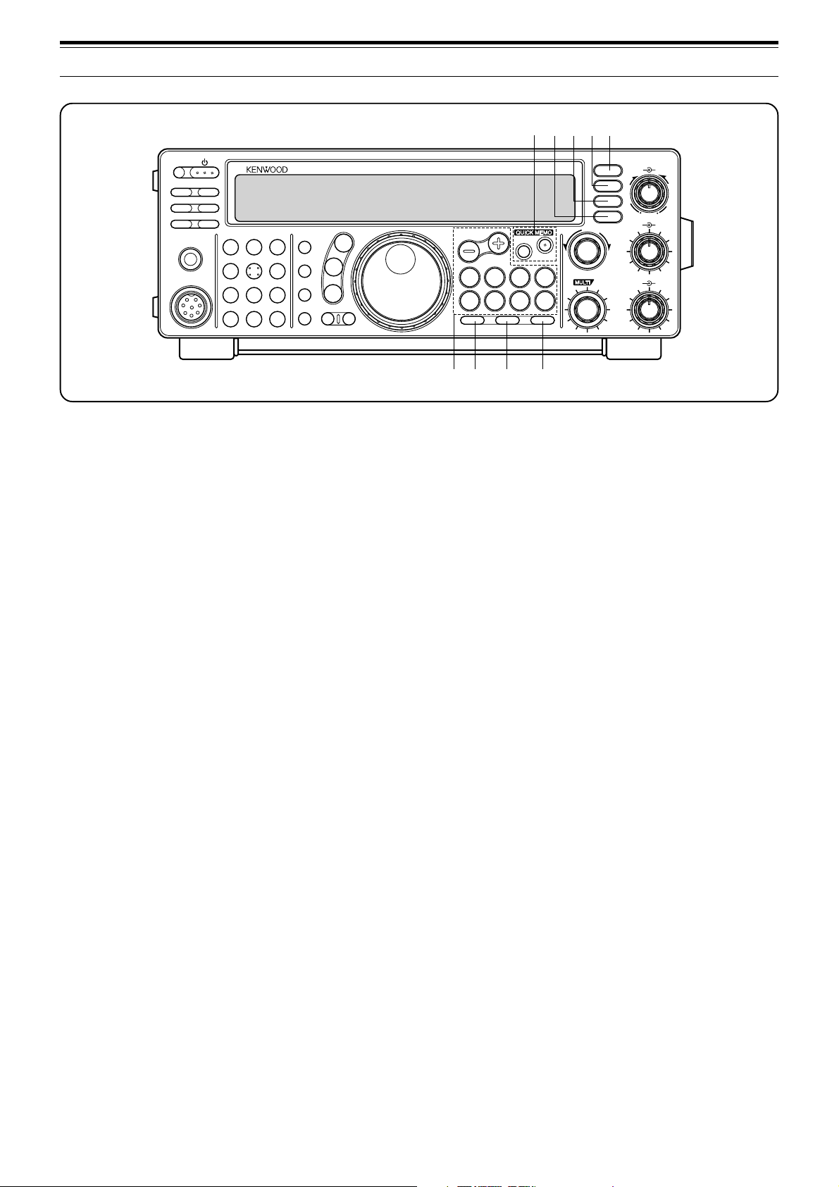
!2!2
!2 Transmit function buttons
!2!2
Used in conjunction with the MULTI/CH control to set
various transmit functions.
• MIC button
Used for setting the microphone gain level
{page15}.
• PWR button
Used for setting the transmit output power
{page15}.
• KEY button
Used for setting the internal electronic keyer speed
{page 34}.
• DELAY button
When using the VOX or Break-in function, used for
setting the time delay from transmit mode to receive
mode {pages 31, 34}.
DSP SLOPE
HIGH
LOW
T
U
C
W
O
L
AF RF
46
28
010
IF SHIFT SQL
46
28
010
UP
DOWN
SPLIT
TF-SET
M/V
A=B
SCAN M>VFO M.IN
CLEAR
N.R.
B.C.
CW TUNE
FILTER
MR
M.IN
A/B
RIT
XIT
RIT/XIT
+–
CH
!6
!3!3
!3 Mode buttons
!3!3
Press these buttons to select your operating mode
{page14}.
• LSB/USB button
Press to select lower sideband or upper sideband
mode for voice or digital operation {pages 20, 27}.
• CW/FSK button
Press to select CW or frequency shift keying mode
{pages 21, 26}.
• FM/AM button
Press to select FM or AM mode {page 22}.
!4!4
!4 MENU button
!4!4
Press to select or cancel the Menu mode that is used for
activating and configuring functions {page 16}.
!5!5
!5 1MHz button
!5!5
Press to switch between the 1 MHz step mode and the
Amateur band mode {page 29}.
!6!6
!6 Tuning control
!6!6
Turn to select the desired frequency {page 14}. Use the
convenient finger-tip cavity for continuous tuning.
The lever behind the control adjusts the control torque
level; turn fully clockwise for light torque or fully
counterclockwise for slightly heavy torque.
7
Page 14
3 GETTING ACQUAINTED
@1
@2
@3@4@5
PF
ATT PRE-AMP
VOX PROC
AT TUNE
SEND
PHONES
!7!7
!7 Frequency control buttons
!7!7
CH1
ANT4REC5FINE
MIC
CLR
CH22CH3
1
NB7AGC/TONE8REV
F.LOCK
3
6
9
ENT
0
HF TRANSCEIVER TS-570D
MIC
LSB
USB
PWR
CW
FSK
KEY
FM
AM
DELAY MENU 1MHz
These buttons control functions related to selecting a
frequency, a VFO, or a memory channel.
• UP/DOWN buttons
Press to step through all Amateur bands
consecutively {page 13} or to step the transceiver
frequency in 1 MHz increments {page 29}. Also
used for making selections from the Menu
{page16}, and to check Start and End frequencies
for the Scan function {page 43}.
• SPLIT button
Press to use split-frequency operation which allows
a different transmit frequency and receive frequency
{page 23}.
• M/V button
Press to select either Memory or VFO mode
{page40}.
• TF-SET button
While operating split-frequency, press to monitor or
change your transmit frequency {page 23}.
• A=B button
Press to copy the data in the currently selected VFO
over to the other VFO {page 30}.
• A/B button
Press to select either VFO A or VFO B {page 13}.
Also, in menu mode, press to select either Menu A
or Menu B {page 16}.
• CLEAR button
Press to reset the RIT/XIT frequency offset to zero
{pages 30, 32}.
• RIT button
Press to switch ON or OFF the Receive Incremental
Tuning function {page 30}.
• XIT button
Press to switch ON or OFF the Transmit
Incremental Tuning function {page 32}.
8
DSP SLOPE
HIGH
LOW
T
U
C
W
O
L
AF RF
46
28
010
46
28
010
UP
DOWN
SPLIT
TF-SET
M/V
A=B
SCAN M>VFO M.IN
A/B
CLEAR
N.R.
B.C.
CW TUNE
FILTER
MR
M.IN
RIT
XIT
RIT/XIT
CH
+–
IF SHIFT SQL
!7 ! 8 !9 @0
!8!8
!8 SCAN button
!8!8
Press to start and stop Scan functions {pages 46, 47}.
!9!9
!9 M>VFO button
!9!9
Press to transfer data from a memory channel to a VFO
{page 42}.
@0@0
@0 M.IN button
@0@0
Writes data into a memory channel {page 39} or selects
Memory Scroll mode {page 41}.
@1@1
@1 Quick Memory buttons
@1@1
Controls the Quick Memory function {page 44}.
• M.IN button
Press to write data into Quick Memory {page 44}.
• MR button
Press to recall data from Quick Memory {page 45}.
@2@2
@2 FILTER button
@2@2
Press to select the receive filter bandwidth in SSB, CW,
FSK, or AM mode {pages 36, 38}, or press to select
either narrow-band or wide-band transmit deviation in
FM mode {page 22}.
Note:
Selecting the narrow filter bandwidth in SSB mode requires
the optional YK-88SN-1 filter {page 36}.
@3@3
@3 CW TUNE button
@3@3
Press to activate the automatic zero-beat function for
CW mode {page 21}.
@4@4
@4 B.C. button
@4@4
Press to switch ON or OFF the DSP Beat Cancel
function {page 38}.
@5@5
@5 N.R. button
@5@5
Press to toggle between Noise Reduction 1, Noise
Reduction 2, and OFF {page 38}.
Page 15
3 GETTING ACQUAINTED
@8
PF
ATT PRE-AMP
VOX PROC
SEND
AT TUNE
MIC
CH1
1
ANT4REC5FINE
NB7AGC/TONE8REV
CLR
PHONES
@6@6
@6 DSP SLOPE (HIGH) control
@6@6
CH22CH3
F.LOCK
3
6
9
ENT
0
HF TRANSCEIVER TS-570D
MIC
LSB
USB
PWR
CW
FSK
KEY
FM
AM
DELAY MENU 1MHz
In SSB or AM mode, turn to change the high cut-off
frequency of the receive pass band. Use the control to
improve readability of the desired signal when higher
frequency interference is present {page 37}.
@7@7
@7 DSP SLOPE (LOW) control
@7@7
In SSB or AM mode, turn to change the low cut-off
frequency of the receive pass band. Use the control to
improve readability of the desired signal when lower
frequency interference is present {page 37}.
DSP SLOPE
HIGH
LOW
T
U
C
W
O
L
AF RF
46
28
010
IF SHIFT SQL
46
28
010
@6
@7
@9
#0
#1
#2
UP
DOWN
TF-SET
SPLIT
M/V
A=B
SCAN M>VFO M.IN
A/B
CLEAR
N.R.
B.C.
CW TUNE
FILTER
MR
M.IN
RIT
XIT
RIT/XIT
+–
CH
#3
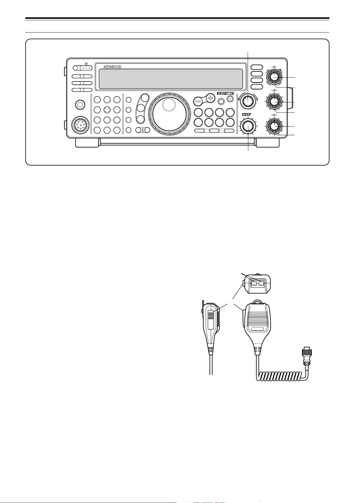
MICROPHONE
qq
q UP/DWN buttons
qq
Use these buttons to step up or down the VFO
frequency, memory channels, or Menu selections.
Press and hold down to continuously change the
settings.
ww
w PTT (Push-to-Talk) switch
ww
The transceiver is placed in transmit mode when this
non-locking switch is held down. Releasing the switch
returns the transceiver to receive mode.
@8@8
@8 RIT/XIT control
@8@8
After switching ON the RIT or XIT function, turn to
select the desired frequency offset {pages 30, 32}.
@9@9
@9 AF control
@9@9
Turn to adjust the audio frequency gain {page 13}.
#0#0
#0 RF control
#0#0
Turn to adjust the radio frequency gain {page 13}.
#1#1
#1 IF SHIFT control
#1#1
Turn to slide the receive pass band either lower or
higher in frequency when interference is present
{page36}.
#2#2
#2 SQL control
#2#2
Used for muting (“squelching”) the speaker output when
no receive signal is present {page 14}.
#3#3
#3 MULTI/CH control
#3#3
In VFO mode, turn to step the operating frequency up
or down {page 29}. In memory channel mode, turn to
select a memory channel {page 40}. Also used for
selecting Menu numbers when accessing the Menu
mode {page 16}, and as a selector to choose settings
for various functions activated by front panel buttons.
q
DWN UP
w
PTT
9
Page 16
3 GETTING ACQUAINTED
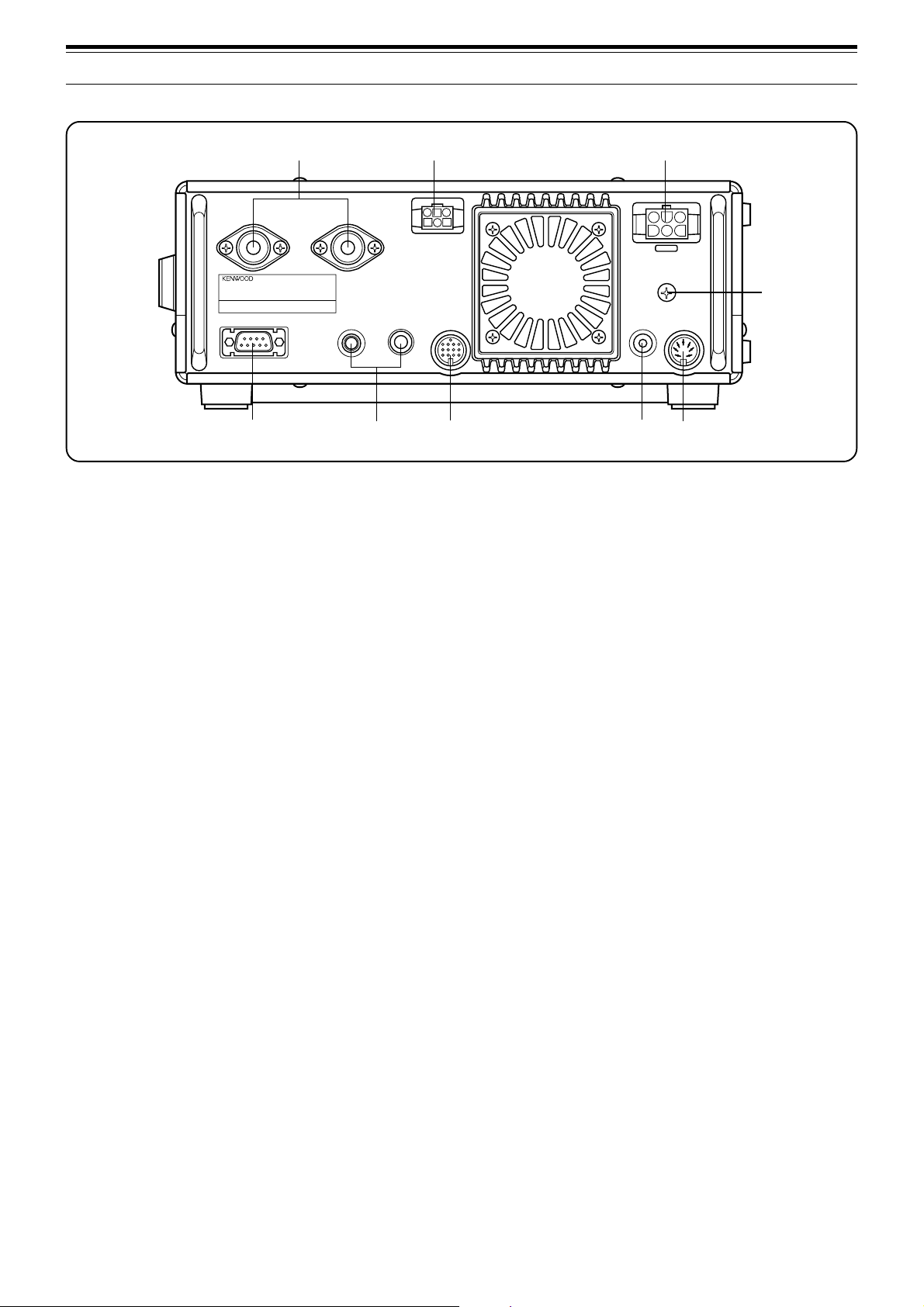
REAR PANEL
q
ANT 2
COM
t
qq
q ANT 1 and ANT 2 connectors
qq
Connect the feed lines from your antennas to these
connectors. Refer to pages 1 and 48 for details.
ww
w AT connector
ww
Mates with the connector on the cable supplied with the
external antenna tuner. Refer to the instruction manual
supplied with this tuner for more information.
ee
e DC 13.8 V power input connector
ee
Connect a 13.8 V DC power source {page 2}. Use the
supplied cable with a regulated DC power supply.
ANT 1
KEY
PADDLE ACC 2
y
w
AT
e
DC 13.8V
GND
EXT.SP
REMOTE
8Ω
o
u
ii
i EXT SP jack
ii
Mates with a 3.5 mm (1/8"), 2-conductor (mono) plug for
connecting an external speaker {page 3}. Connecting
an external speaker cuts off the audio automatically to
the internal speaker.
oo
o REMOTE connector
oo
Mates with a 7-pin male DIN connector for connecting a
linear amplifier {page 61}.
European versions only:
COM
connectors, remove the protective covers.
i
Before connecting to the
r
ACC 2
and
rr
r GND post
rr
Connect a heavy gauge wire or copper strap between
the ground post and the nearest earth ground {page 2}.
tt
t COM connector
tt
Mates with a 9-pin female RS-232C connector for
connecting a computer via one of its serial
communication ports {page 60}. Also used with the
Quick Data Transfer function {page 60}.
yy
y KEY and PADDLE jacks
yy
The PADDLE jack mates with a 6.0 mm (1/4")
3-conductor plug for connecting a keyer paddle to the
internal electronic keyer. The KEY jack mates with a
3.5 mm (1/8") 2-conductor plug for connecting an
external key for CW operation. Read “Keys and
Keyboards for CW Operation” {page 3} before
connecting to these jacks.
uu
u ACC 2 connector
uu
Mates with a 13-pin male DIN connector for connecting
various accessory equipment {pages 61, 62}.
10
Page 17
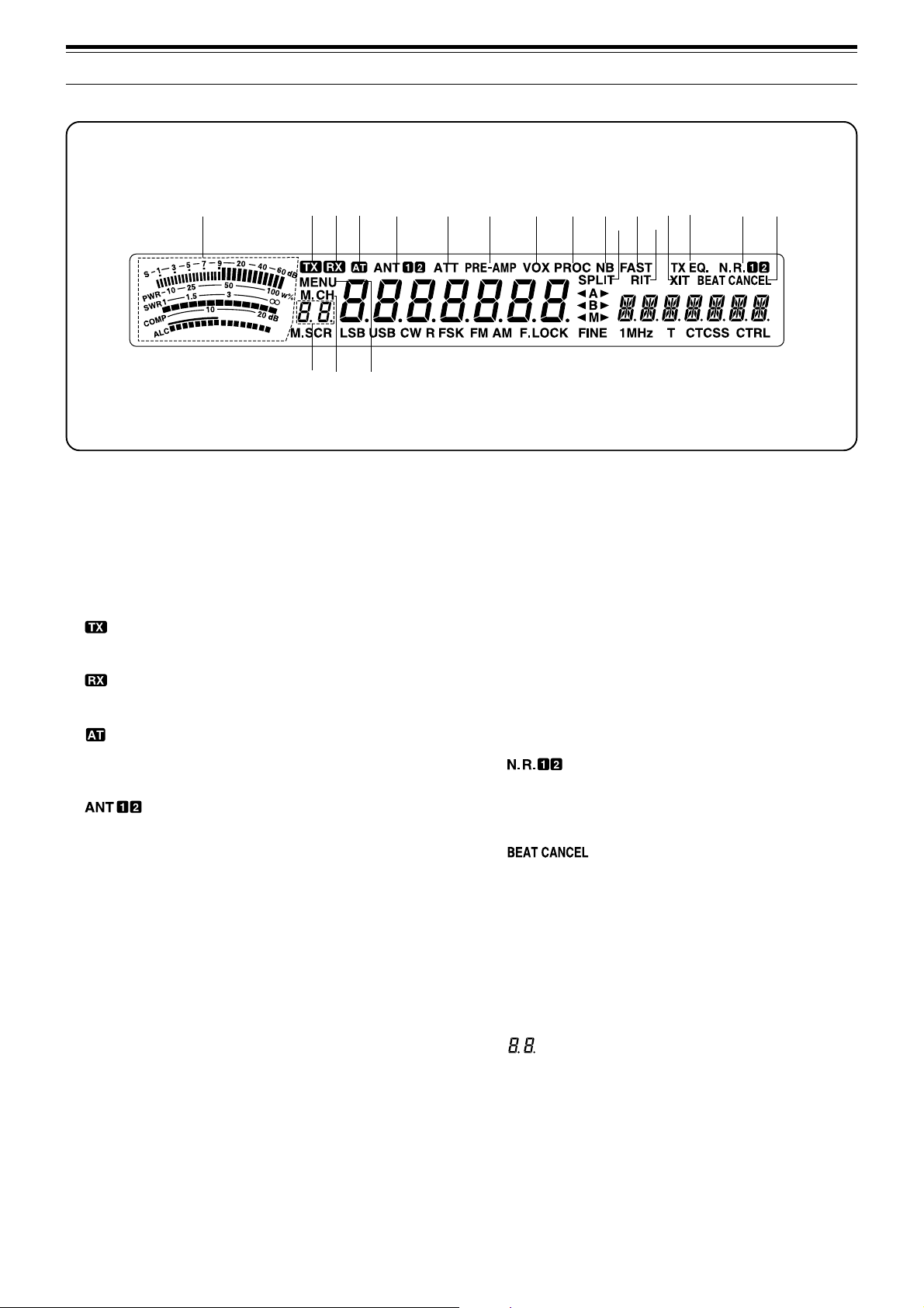
DISPLAY
qw
e
rt y
!9
!8@0
u
i
o
!0
!1
3 GETTING ACQUAINTED
!2
!6 !7
!5
!4
!3
qq
q METER
qq
While receiving, serves as an S-meter to measure and
display the received signal strength. While transmitting,
serves as a calibrated power meter plus an ALC meter,
an SWR meter, or a Speech Processor compression
meter. The Peak Hold function holds each reading for
about 2.5 seconds.
ww
w
ww
Appears while the transceiver is in the transmit mode.
ee
e
ee
Appears while the squelch is open in the receive mode.
rr
r
rr
Appears while the internal antenna tuner {page 52} or an
external antenna tuner is in-line.
tt
t
tt
Either “ANT 1” or “ANT 2” appears depending on
whether the Antenna 1 connector or the Antenna 2
connector is selected {page 48}.
yy
y ATT
yy
Appears when the receive attenuator is ON {page 37}.
uu
u PRE -AMP
uu
Appears when the receive preamplifier is ON {page 37}.
ii
i VOX
ii
Appears when the Voice-Operated Transmit function is
ON {page 31}. For CW operation, appears when the
Break-in function is ON {page 34}.
oo
o PROC
oo
Appears when Speech Processor is ON {page 32}.
!0!0
!0 NB
!0!0
Appears when Noise Blanker is ON {page 36}.
!1!1
!1 SPLIT
!1!1
Appears when the transmit frequency differs from the
receive frequency {page 23}.
!2!2
!2 FAST
!2!2
Appears when a fast time constant is selected for the
Automatic Gain Control function {page 30}.
!3!3
!3 RIT
!3!3
Appears when Receive Incremental Tuning is ON
{page30}.
!4!4
!4 XIT
!4!4
Appears when Transmit Incremental Tuning is ON
{page 32}.
!5!5
!5 TX EQ.
!5!5
Appears when the TX Equalizer function is ON
{page33}.
!6!6
!6
!6!6
Either “N.R. 1” or “N.R. 2” appears depending on
whether Noise Reduction 1 or Noise Reduction 2 is
selected {page 38}.
!7!7
!7
!7!7
Appears when Beat Cancel is ON {page 38}.
!8!8
!8 MENU
!8!8
Appears while Menu mode is being accessed
{page16}.
!9!9
!9 M.CH
!9!9
Appears while Memory Recall or Memory Scroll is
being used {page 40}.
@0@0
@0
@0@0
Shows 2-digit information such as a menu number or a
memory channel number.
11
Page 18
3 GETTING ACQUAINTED
@1
@3
@2
@4 @5
@6
@7
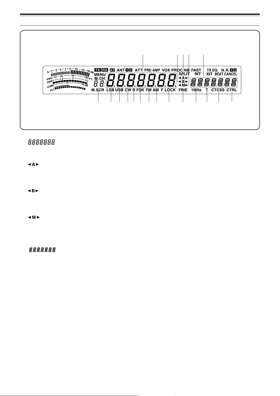
@1@1
@1
@1@1
Shows the current operating frequency. Also shows
Menu selections while in Menu mode.
@2@2
@2
@2@2
“tA” or “As” appears while VFO A is being selected
{page13}. “A” appears while Menu A is being
accessed {page16}.
@3@3
@3
@3@3
“tB” or “Bs” appears while VFO B is being selected
{page13}. “B” appears while Menu B is being
accessed {page16}.
@4@4
@4
@4@4
“tM” or “Ms” appears while a simplex memory
channel is being selected {page 40}. “tMs” appears
while a split-frequency memory channel is being
selected {page 40}.
@5@5
@5
@5@5
Shows menu information while Menu A or B is being
accessed. Also shows the transmit frequency during
split-frequency operation, and the RIT/XIT offset
frequency when these functions are ON.
@6@6
@6 M.SCR
@6@6
Appears while Memory Scroll is being used {page 41}.
@7@7
@7 LSB
@7@7
Appears when in Lower Sideband mode {page 14}.
@8@8
@8 USB
@8@8
Appears when in Upper Sideband mode {page 14}.
@9@9
@9 CW
@9@9
Appears when in CW mode {page 14}.
@8
@9 #0
#8
#1
#3
#2
#0#0
#0 R
#0#0
Appears while the sideband is being reversed for CW
{page 21}. Also appears while the mark and space
frequency relationship is being reversed for FSK
{page26}.
#1#1
#1 FSK
#1#1
Appears when in Frequency Shift Keying mode
{page26} or when you select one of the digital operation
filters via Menu No. 32 in SSB mode {page27}.
#2#2
#2 FM
#2#2
Appears when in FM mode {page 14}.
#3#3
#3 AM
#3#3
Appears when in AM mode {page 14}.
#4#4
#4 F.LOCK
#4#4
Appears when the Frequency Lock function is ON
{page48}.
#5#5
#5 FINE
#5#5
Appears when the Fine function is ON {page 29}.
#6#6
#6 1MHz
#6#6
Appears when the 1 MHz Step function is ON {page29}.
#7#7
#7 T
#7#7
Appears when the Subtone function is ON {page 24}.
#8#8
#8 CTCSS
#8#8
Appears when CTCSS is ON {page 25}.
#9#9
#9 CTRL
#9#9
Appears while Quick Data Transfer {page 50} or
Computer Control {page 51} is being used.
#4
#5
#6
#7
#9
12
Page 19
OPERATING BASICS
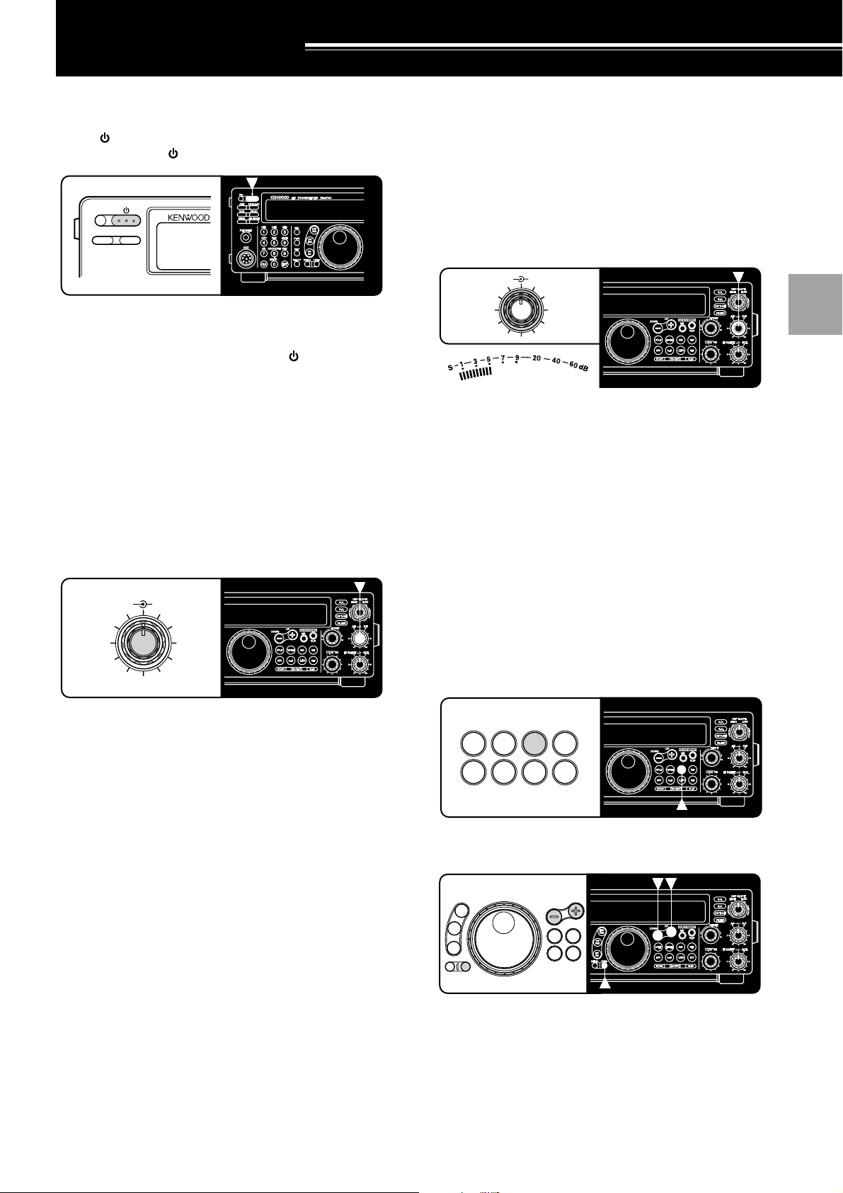
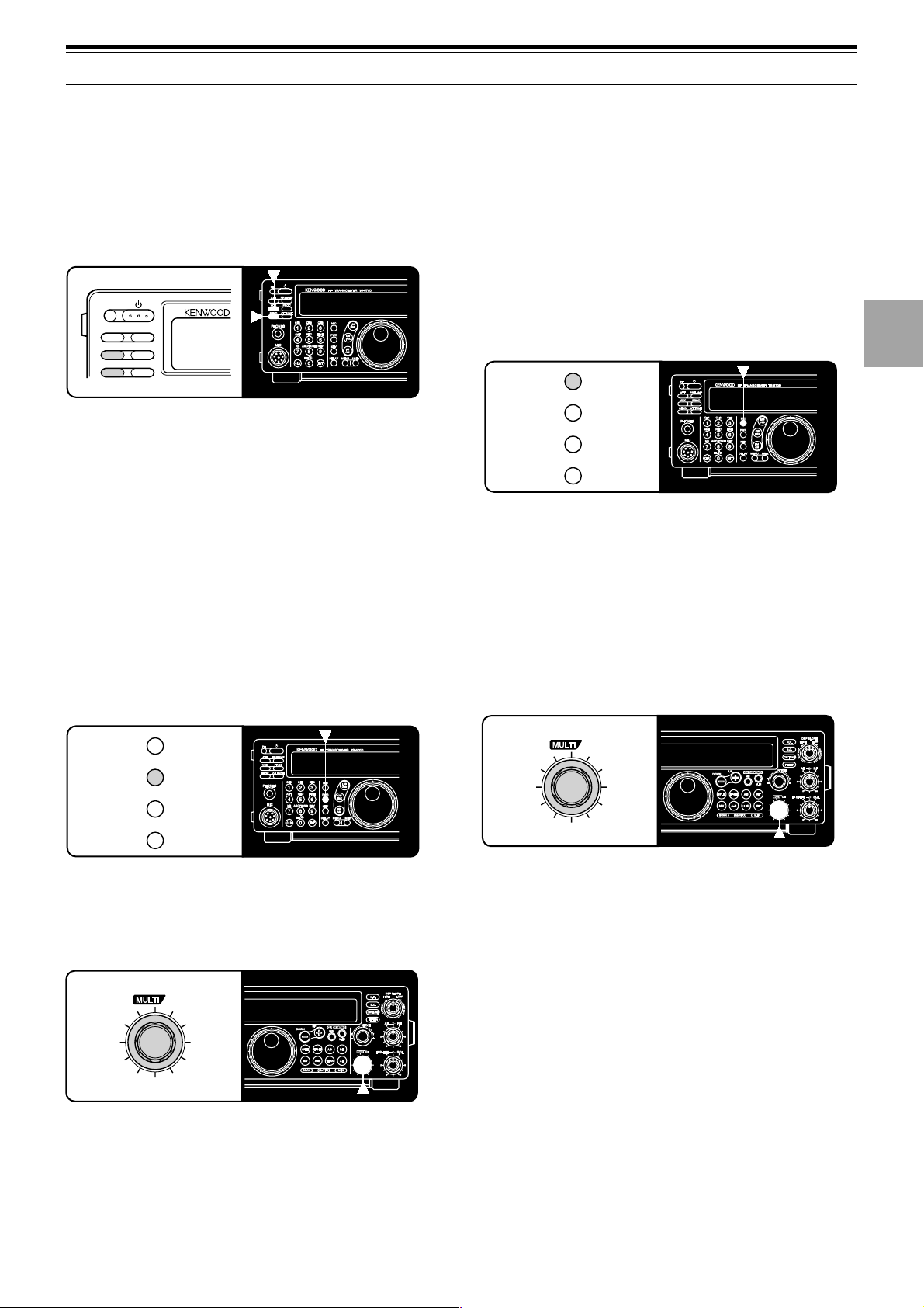
SWITCHING POWER ON/OFF
Switch ON the DC power supply, then press and hold
down [
] (POWER) until “HELLO” appears on the
display. Release [ ] (POWER) when you see “HELLO”.
PF
ATT PRE-AMP
• After the “HELLO” message, the frequency and
other indicators appear.
To switch OFF the transceiver, press [ ] (POWER).
• After the transceiver has been switched ON, it can
then be switched OFF or ON by using only the
power switch on the DC power supply.
ADJUSTING VOLUME
RADIO FREQUENCY (RF) GAIN
Usually, set the RF control fully clockwise. If you are
having trouble hearing the desired signal due to
excessive atmospheric noise or interference from other
stations, it may help to reduce the RF gain.
To do this, take note of the peak S-meter reading of the
desired signal. Turn the RF control counterclockwise
until the S-meter reads the peak value that you noted.
Signals that are weaker than this level will be
attenuated. Reception of the station will be easier.
AF RF
46
2
010
Depending on the type and gain of your antenna, and
the condition of the band, you may prefer leaving the RF
control turned counterclockwise by some amount
instead of turning it fully clockwise. When in FM mode,
always set the RF gain control fully clockwise.
8
QUICK MEMO
1
2
3
4
5
6
AUDIO FREQUENCY (AF) GAIN
Turn the AF control clockwise to increase the audio
level and counterclockwise to decrease the level.
AF RF
46
QUICK MEMO
2
010
Note:
The position of the AF control does not affect the volume of
“beeps” caused by pressing buttons nor the CW transmit sidetone.
Also, the audio level for Packet operation is independent of the
control setting.
8
AF
SELECTING VFO A OR VFO B
VFO A and VFO B are modes that allow any desired
frequency to be selected within the frequency range of
the transceiver. VFO A and VFO B function
independently so that different or the same frequencies
can be selected for each VFO.
Press [A/B] to toggle between VFO A and VFO B.
•“tA” or “tB” appears and shows which VFO is
selected.
SPLIT
TF-SET
A/B
M/V
A=B
CLEAR
RIT
XIT
QUICK MEMO
SELECTING A BAND
UP
LSB
USB
CW
FSK
FM
AM
MENU 1MHz
DOWN
TF-SET
SPLIT
M/V
A=B
QUICK MEMO
7
8
9
10
11
12
13
14
1 If “1MHz” is visible on the display, first press [1MHz]
to exit from the 1MHz Step mode.
• “1MHz” should disappear.
2 Press [UP] or [DOWN].
• Holding down either button consecutively steps
the transceiver to each band.
15
16
13
Page 20
4 OPERATING BASICS
1
2
3
4
5
6
7
8
9
10
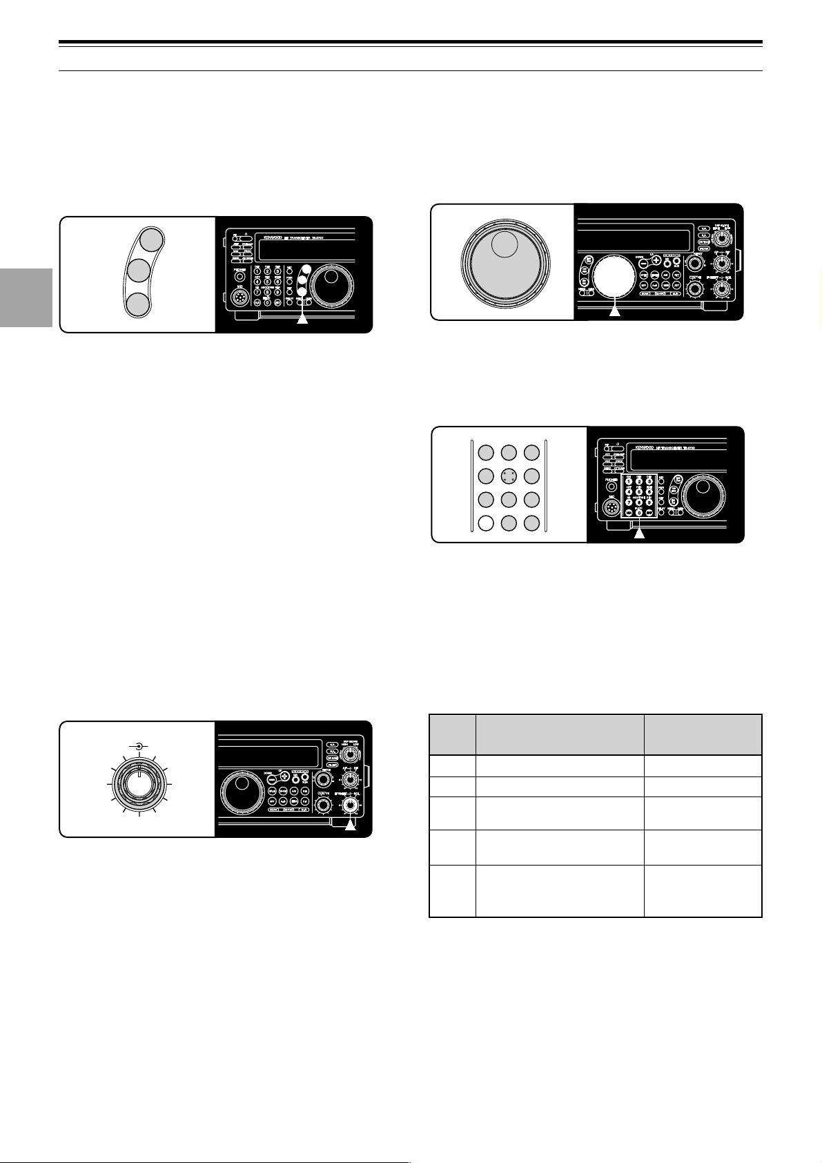
SELECTING A MODE
Depending on which operating mode you want to select,
press the [LSB/USB], [CW/FSK], or [FM/AM] button.
The second function on each button is accessed by
again pressing the same button. For example,
repeatedly pressing [LSB/USB] toggles between LSB
and USB modes.
LSB
USB
CW
FSK
FM
AM
In SSB mode, the transceiver automatically selects LSB
for frequencies lower than 9.5 MHz, and selects USB for
9.5 MHz or higher frequencies if the Tuning control, the
MULTI/CH control, or Mic [UP]/[DWN] is used to cross
the frequency of 9.5 MHz. This is also true if using the
front panel [UP] or [DOWN] button when the 1 MHz
Step mode is used.
ADJUSTING SQUELCH
The purpose of squelch is to silence audio output from
the speaker when no signal is present. When squelch
is set correctly, you will hear sound only while a station
is actually being received. The point at which ambient
noise on a frequency just disappears, called the squelch
threshold, depends on the frequency.
Turn the SQL control clockwise to just eliminate the
background noise when no signal is present. Many
operators prefer leaving the squelch control fully
counterclockwise unless operating full-carrier modes
such as FM or AM.
SELECTING A FREQUENCY
There are two simple methods to select a frequency.
A Manual Tuning
Turn the Tuning control or press Mic [UP]/[DWN] to
select the exact frequency.
QUICK MEMO
B Direct Frequency Entry (Keypad)
Press [ENT], then directly enter the desired
frequency using the numeric keypad. For details,
refer to “Direct Frequency Entry” {page 29}.
CH11CH22CH3
ANT4REC5FINE
NB7AGC/TONE8REV
CLR
F.LOCK
0
3
6
9
ENT
FRONT PANEL METER
The multifunction meter measures the parameters in the
table below. The appropriate meters automatically
become functional according to which state the
transceiver is in. Peak readings for the S-meter, ALC,
SWR, COMP, and PWR functions are held for a brief
moment.
11
12
13
14
15
16
IF SHIFT SQL
14
46
2
010
Scale
S
QUICK MEMO
8
PWR
ALC
SWR
COMP
Note:
◆
◆
Received signal strength
Transmit output power
Automatic level control
status
Antenna system standing
wave ratio
Speech compression level
when using the Speech
Processor {page 32}
The COMP meter functions only when the Speech Processor is
ON while using SSB, FM, or AM mode. When the COMP meter
appears, the SWR meter disappears.
Peak Hold readings cannot be deactivated on this transceiver.
Display
Functional State
Receive
Transmit
Transmit
Transmit
Transmit plus
SSB/AM/FM mode
plus [PROC] ON
Page 21
4 OPERATING BASICS
TRANSMITTING
Methods for transmitting include the following:
• Press [SEND].
• Press and hold down Mic [PTT].
• Connect a key or keyer paddle, select the CW mode,
press [VOX] to switch ON the Break-in function, and
close the key or keyer paddle.
PF
ATT PRE-AMP
VOX PROC
SEND AT TUNE
For a detailed explanation on transmitting, refer to
sections in “BASIC COMMUNICATING” beginning on
page 20.
Note:
When CW, FSK, or AM is selected, the transmit carrier level is
automatically adjusted according to the selected mode.
SELECTING TRANSMIT POWER
It’s wise, and required by law, to select the lowest
transmit power that allows reliable communication.
Reducing power lowers the risk of interfering with others
on the band. On this transceiver, it is possible to
change output power while transmitting.
1 Press [PWR].
• The current transmit power appears.
3 Press [PWR] again to complete the setting.
Note:
The transmit power can be separately selected for the AM
mode independent of the other modes.
MICROPHONE GAIN
The microphone gain is finely adjustable in the SSB or
AM mode. A different level can be selected between
when the Speech Processor {page 32} is ON and when
the Speech Processor is OFF.
1 Press [MIC].
• The current microphone gain level appears. The
default is 50.
MIC
PWR
KEY
DELAY
2 Press [SEND] or press and hold Mic [PTT].
• “TX” appears.
3 SSB: While speaking into the microphone, adjust
the MULTI/CH control so that the ALC meter reflects
according to your voice level.
AM: While speaking into the microphone, adjust the
MULTI/CH control so that the calibrated power meter
slightly reflects according to your voice level.
1
2
3
4
5
6
7
8
9
MIC
PWR
KEY
DELAY
2 Turn the MULTI/CH control counterclockwise to
reduce power and clockwise to increase power.
• The displayed transmit power changes.
CH
QUICK MEMO
• SSB/CW/FSK/FM: Transmit power can be
changed from 5 W to 100 W in steps of 5 W.
• AM: Transmit power can be changed from 5 W to
25 W in steps of 5 W.
CH
QUICK MEMO
4 Press [SEND] again or release Mic [PTT].
• “TX” disappears.
5 Press [MIC] again.
For the FM mode, set the microphone gain by
accessing Menu No. 17 {page 17} and selecting either
“L” (low) or “H” (high).
Note:
◆
When using the optional MC-90 microphone in FM mode, select
high microphone gain. The microphone sensitivity is low in FM
mode and this may cause insufficient modulation.
◆
When using a microphone that has an amplifier, be careful that
the output of the amplifier is not too large.
10
11
12
13
14
15
16
15
Page 22

MENU SETUP
WHAT IS A MENU?
Many functions on this transceiver are selected or
configured via a software-controlled Menu instead of
physical controls on the transceiver. Once familiar with
the Menu system, you will appreciate the versatility it
offers. No longer is the number and complexity of
features restricted by the physical controls and
switches on the front panel.
MENU A/ MENU B
The transceiver has two menus. These menus are
called MenuA and MenuB. The menus contain
identical functions; however, each menu can be
configured independently.
For example, you may enjoy two different kinds of
operating activities but you like to configure the
transceiver differently for each activity. MenuA could
be configured with one set of transmit signal
characteristics, DSP settings, programmable buttons,
frequency steps, etc. MenuB could be configured
completely differently. By switching from MenuA to
MenuB, you could instantly change Menu
configuration and button assignment to suit your
current operating style. Or, two operators may share a
single transceiver. By dedicating one Menu per
operator, each would always enjoy the best
configuration.
Note:
The COM communication parameter setting in Menu No. 35
is shared by Menu A and Menu B.
MENU ACCESS
The following procedure explains how to check or
change any of the Menu items.
1 Press [MENU].
• “MENU” appears.
2 Press [A/B] to toggle Menu A or Menu B.
• “A” or “B” appears to show which Menu is
selected.
3 Turn the MULTI/CH control to select the desired
Menu No.
• Each time you change the Menu No. , you will
see a scrolling message that briefly describes the
current Menu No.
4 Press [UP], [DOWN], Mic [UP], or Mic [DWN] to
change the current selection for this Menu item.
5 Press [MENU] or [CLR] to exit Menu mode.
16
Page 23

MENU CONFIGURATION
5 MENU SETUP
Group
Operator
Interface
Encoder
Memory
Channel
Menu
No.
00
01
02
03
04
05
06
07
08
Function
Display brightness
d1: maximum, d4: minimum
Beep output level
1: minimum, 9: maximum
Frequency step size for the [UP]/[DOWN]
buttons in the 1 MHz step mode
Frequency step size for the MULTI/CH control
for SSB, CW, FSK, or AM mode
Frequency step size for the MULTI/CH control
for FM mode
Rounds off VFO frequencies changed by using
the MULTI/CH control
Frequency step size for the MULTI/CH control
for AM mode in the AM broadcast band
Memory-VFO split operation
Tunable (ON) or fixed (OFF) memory channel
frequencies
Selections
OFF/ d4/ d3/ d2/ d1
OFF, 1 to 9
100/ 500/ 1000 kHz
1/ 5/ 10 kHz
1/ 5/ 10/ 12.5/
20/ 25 kHz
ON/ OFF
9 kHz/ 10 kHz
ON/ OFF
ON/ OFF
Default
d2
4
1000 kHz
10 kHz
10 kHz
ON
See page
reference
OFF
OFF
Page
Ref.
49
49
29
29
29
29
29
41
41
Scan
Antenna Tuner
DSP
TX
Program scan hold
09
Scan resume method
10
Antenna tuner operation while receiving signals
11
Time constant for the noise reduction 2 function
12
TX filter bandwidth for SSB or AM mode
13
TX equalizer
14
OFF: flat, Hb: high boost, FP: formant pass,
bb: bass boost, c: conventional
Speech processor compression level
15
VOX gain
16
0: minimum, 9: maximum
Microphone gain for FM mode
17
L: low, H: high
Subaudible tone frequency for FM mode
18
Type of subaudible tone for FM mode
19
B: burst, C: continuous
ON/ OFF
Time-operated/
Carrier-operated
ON/ OFF
7.5/ 20 ms
2.4/ 2.0 kHz
OFF/ Hb/ FP/ bb/ c
(U: not currently
available)
0 to 25 dB in
steps of 5 dB
0 to 9
L/ H
See page reference
B/ C
OFF
Time-
operated
OFF
20 ms
2.4 kHz
OFF
10 dB
4
L
88.5 Hz
See page
reference
46
47
52
38
33
33
32
31
22
25
25
CW
DRU
CW RX pitch/ TX sidetone frequency
20
TX sidetone volume
21
Semi-automatic key (“Bug”) function
22
Playback repeat
23
Interval between repeated playbacks
24
Playback volume
25
1: minimum, 9: maximum
400 to 1000 Hz in
steps of 50 Hz
OFF, 1 to 9
ON/ OFF
ON/ OFF
0 to 60 sec
OFF, 1 to 9
800 Hz
5
OFF
OFF
10 sec
4
21
21
35
35, 53
54
54
17
Page 24

5 MENU SETUP
Group
CW
Digital
Operation
Computer
Interface
Data Transfer
Menu
No.
26
27
28
29
30
31
32
33
34
35
36
37
Function
CW Auto weighting
CW Auto weighting reversed
Keying priority over playback
FSK shift
Key-down polarity for FSK mode
Tone frequencies for FSK mode
2125: 2125 Hz mark, 1275: 1275 Hz mark
Filter bandwidth for digital operation
(SSB and FM modes only)
AF input level for digital operation
(excluding CW and FSK modes)
0: minimum, 2: maximum
AF output level for digital operation
0: minimum, 9: maximum
Communication parameters for COM connector
Setting Transfer Rate (bps) Stop Bits
12-1
24-1
48-1
48-2
96-1
192-1
384-1
576-1
1200
2400
4800
4800
9600
19200
38400
57600
1
1
1
2
1
1
1
1
Data transfer enable
Method of receiving transferred data
ON: Transfer to VFO
OFF: Transfer to quick memory
Selections
ON/ OFF
ON/ OFF
ON/ OFF
170/ 200/ 425/ 850 Hz
ON (space)/ OFF (mark)
2125/ 1275 Hz
OFF/ 1200 bps/
300 bps/ PSK
0/ 1/ 2
0 to 9
12-1/ 24-1/ 48-1/ 48-2/
96-1/ 192-1/ 384-1/
576-1
Note: To reliably use the
38400 or 57600 bps transfer
rates, the serial port of your
computer must support these
high-speed communications
parameters.
ON/ OFF
ON/ OFF
Default
ON
OFF
OFF
170 Hz
OFF
2125 Hz
OFF
2
4
96-1
OFF
OFF
Page
Ref.
34
34
35
26
26
26
27
27
27
51
50
50
TX
Transverter
PF
RX
TX inhibit
38
Linear amplifier control relay
39
Enables/disables the 50, 144, or 430 MHz
40
transverter function.
Programs the [PF] button on the front panel.
41
Programs the Mic [PF1] button.
42
Programs the Mic [PF2] button.
43
Programs the Mic [PF3] button.
44
Programs the Mic [PF4] button.
45
IF filter bandwidth
46
ON/ OFF
ON/ OFF
OFF/ 50/ 144/ 430 MHz
See page reference
See page reference
See page reference
See page reference
See page reference
OFF/
1800/ 500/ 270 Hz
OFF
OFF
OFF
51
(Voice 1)
64
([A/B])
62
([SPLIT])
65
([M/V])
50
(Monitor)
OFF
33
61
51
49
49
49
49
49
36
18
Page 25

5 MENU SETUP
puorG
decnahnE
uneM
.oN
74
84TIRhtiwtaeb-orezotuAFFO/NOFFO12
94egnahcthgiew-dekcolreyeK1:0.4ot1:5.21:0.353
rezilauqeXR
05
15egnahclevel1noitcuderesioN9ot1,otuAotuA83
noitcnuF snoitceleS tluafeD
mumixam:9,muminim:1
CROSS REFERENCE FOR MENU
FUNCTIONS
Use this table arranged by subject to help you locate the
function that you are interested in checking or changing.
Consult “MENU CONFIGURATION” {page17} for more
detail on each function.
Function
AMPLIFIER
Linear amplifier relay
ANTENNA TUNER (AT)
RX enable/ disable
BEEP FUNCTIONS
Beep level
CW
Auto weighting
Auto weighting reversed
Keying priority over playback
RX pitch
Semi-automatic key (“Bug”) function
TX sidetone frequency
TX sidetone volume
DATA TRANSFER
Transfer enable
Transfer method
DIGITAL OPERATION
AF input (MCP/TNC TX)
AF output (MCP/TNC RX)
Filter bandwidth
DISPLAY
Brightness
DRU-3A DIGITAL RECORDING SYSTEM (DRS)
Playback repeat
Playback repeat interval
Playback volume
DIGITAL SIGNAL PROCESSING
NR2 time constant
FM
Microphone gain
Subtone frequency
Subtone type
Menu
No.
39
11
01
26
27
28
20
22
20
21
36
37
33
34
32
00
23
24
25
12
17
18
19
egaP
.feR
emulovrotinomlangis-dettimsnarT
,ssaptnamrof:PF,tsoobhgih:bH,talf:FFO
lanoitnevnoc:c,tsoobssab:bb
Function
FREQUENCY STEPS
MULTI/CH control (SSB, CW, FSK, AM)
MULTI/CH control (FM)
MULTI/CH control (AM and AM broadcast only)
MULTI/CH control (rounds off frequencies)
[UP]/[DOWN] buttons
Polarity (space/mark)
Shift
Tone
MEMORY CHANNELS
Memory-VFO split operation
Tunable/fixed frequency
PROGRAMMABLE BUTTONS
[PF] button
Mic [PF1] button
Mic [PF2] button
Mic [PF3] button
Mic [PF4] button
RECEIVE
IF filter bandwidth
REAR PANEL
COM communication parameters
Hold (Program Scan)
Resume (Time or Carrier)
SPEECH PROCESSOR
Compression level
TRANSMIT
Bandwidth (SSB or AM)
Equalizer
Inhibit
TRANSVERTER
Enable/disable
VOICE-OPERATED TRANSMIT (VOX)
Gain
9ot1,FFOFFO33
c/bb/PF/bH/FFO
yltnerructon:U(
)elbaliava
FSK
SCAN
FFO03
Menu
No.
03
04
06
05
02
30
29
31
07
08
41
42
43
44
45
46
35
09
10
15
13
14
38
40
16
19
Page 26

BASIC COMMUNICATING
SSB TRANSMISSION
SSB is now the most commonly-used mode on the HF
Amateur bands. Compared with other voice modes,
SSB requires a narrow bandwidth for communications.
SSB also allows long distance communication with
minimum transmit power. These reasons, combined
with the fact that modern Amateur transceivers deliver
reasonably good audio quality, make SSB the mode
that most prefer on HF.
Refer, if necessary, to “OPERATING BASICS”
beginning on page 13 for receiving details.
1 Select the operating frequency.
2 Press [LSB/USB] to select either upper or lower
sideband mode.
• “LSB” or “USB” appears to show which sideband
is selected.
6 Release Mic [PTT], or press [SEND] again, to return
to the receive mode.
• “TX” disappears and “RX” appears.
7 Press [MIC] again to quit the Microphone Gain
Setting function.
Refer to “COMMUNICATING AIDS” beginning on
page29 for information about additional useful functions
for operating.
3 Press [MIC] to activate the Microphone Gain Setting
function.
• The current gain level appears
4 Press and hold down Mic [PTT], or press [SEND].
• “RX” disappears and “TX” appears.
• Refer to “VOX” {page 31} for information on
automatic TX/RX switching.
5 Speak into the microphone and adjust the
MULTI/CH control so that the ALC meter reflects
according to your voice level.
• Speak in a normal tone and level of voice.
Speaking too close to the microphone, or too
loudly, may increase distortion and reduce
intelligibility.
•You may want to use the Speech Processor.
Refer to “SPEECH PROCESSOR” {page 32} for
details.
20
Page 27
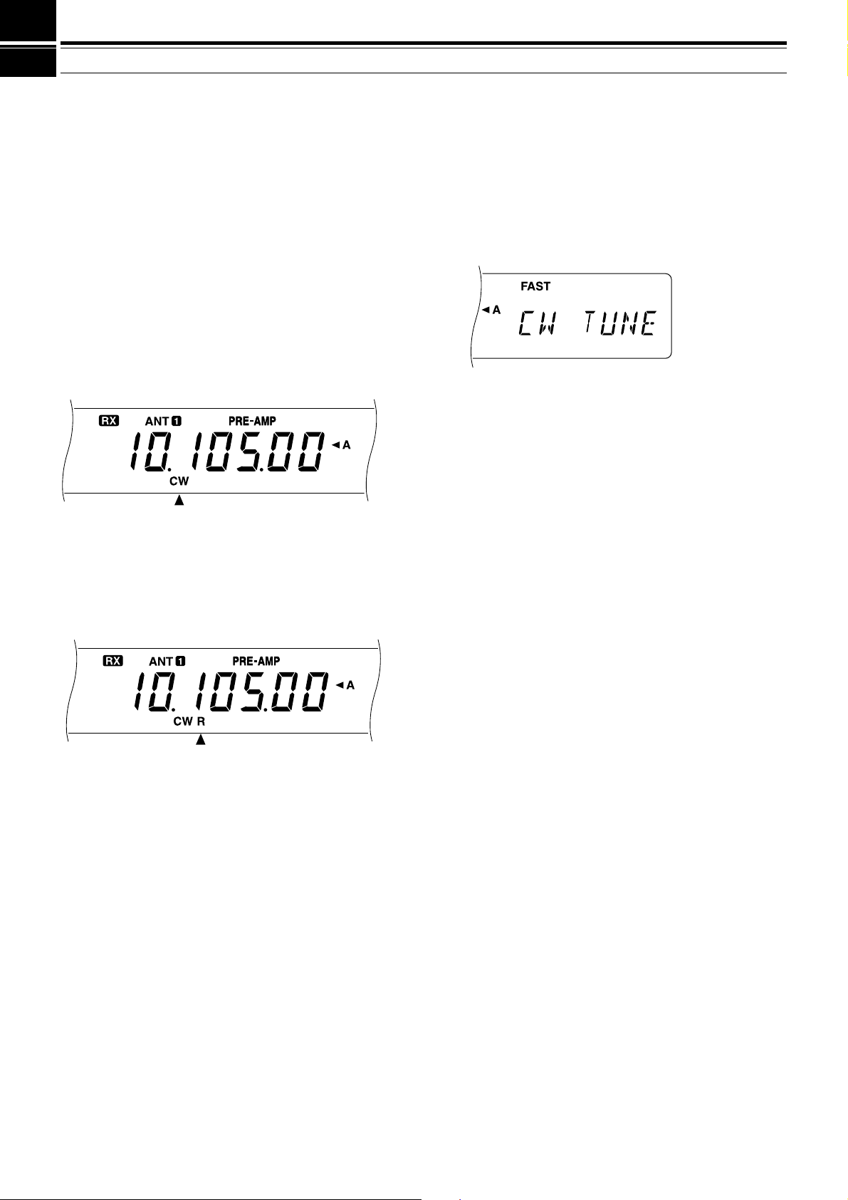
6 BASIC COMMUNICATING
CW TRANSMISSION
CW operators know that this mode is a reliable method
of communicating under the worst conditions. Although
it’s true that newer digital modes rival CW as being
equally as useful in poor conditions, these modes do not
have the long history of service yet nor the simplicity
that CW can have.
This transceiver has a built-in electronic keyer that
supports a variety of functions. For details on using
these functions, refer to “ELECTRONIC KEYER”
{page34}.
Refer, if necessary, to “OPERATING BASICS”
beginning on page 13 for receiving details.
1 Select the operating frequency.
2 Press [CW/FSK] to select CW mode.
• “CW” appears.
•To tune in another station so your transceiver is
precisely on their frequency, use Auto Zero-beat.
Refer to “AUTO ZERO-BEAT”.
• If you wish, you can press [REV] to switch
receive from the default upper sideband to the
lower sideband. “R” will appear.
3 Press [SEND].
• “RX” disappears and “TX” appears.
• No transmit carrier level adjustment is necessary.
• Refer to “CW BREAK-IN” {page 34} for
information on automatic TX/RX switching.
4 Begin sending.
• As you transmit, you should be hearing a
sidetone that lets you monitor your own sending.
Refer to “TX SIDETONE/ RX PITCH
FREQUENCY”.
5 Press [SEND] again to return to the receive mode.
• “TX” disappears and “RX” appears.
Note:
Auto Zero-beating may fail if there are other interfering signals
on frequency.
Refer to “COMMUNICATING AIDS” beginning on
page29 for information about additional useful functions
for operating.
AUTO ZERO-BEAT
Use Auto Zero-beat before transmitting whenever you
need to tune in a CW station. Auto Zero-beat
automatically and exactly matches your transmit
frequency with the station that you are receiving.
Neglecting to do this will reduce your chances for being
heard by the other station.
1 Press [CW TUNE] to start Auto Zero-beat.
• “CW TUNE” appears.
•Your transmit frequency is automatically changed
so that the pitch of the received signal exactly
matches the TX sidetone/ RX pitch frequency
that you have set in your transceiver Menu
configuration. Refer to “TX SIDETONE/ RX
PITCH FREQUENCY” below for further
information on that frequency.
• When matching is completed, “CW TUNE”
disappears.
• If matching is unsuccessful, the previous
frequency is restored.
2 To interrupt Auto Zero-beat, press [CW TUNE] or
[CLR].
Note:
◆
If using RIT {page 30}, you may access Menu No. 48 and switch
the function ON. Auto Zero-beat then will match the RIT-offset
frequency with the station that you are receiving. When this
function is OFF, Auto Zero-beat changes the transmit frequency.
◆
You cannot start Auto Zero-beat if you have selected 1.0 kHz or
2.0 kHz for the DSP filter bandwidth.
◆
When using Auto Zero-beat, the matching error is within ±50 Hz
in most cases.
◆
Auto Zero-beat may fail if the keying speed of the target station is
too slow.
TX SIDETONE/ RX PITCH FREQUENCY
The transmit sidetone is the monitor tone you hear from
your transceiver as you send CW. It is necessary so
you can hear what you are transmitting. It is also useful
for checking that your key contacts are closing, the
keyer is functioning, or for sending practice without
putting a signal on the air.
Receive pitch refers to the frequency of the CW note
that you hear after tuning your receiver for maximum
receive signal strength.
On this transceiver, the frequency of the sidetone and
receive pitch are equal and selectable. Use Menu No.
20 to select the frequency that is most comfortable for
you.
To change the volume of the TX sidetone, use Menu
No. 21. The selections include OFF and 1 to 9. The
default is 4.
Note:
The position of the AF control does not affect the volume of
the TX sidetone.
21
Page 28

6 BASIC COMMUNICATING
FM TRANSMISSION
FM operation on HF frequencies solves the problem of
how to have long distance voice communication with
the finest audio quality. When combined with the fullquieting aspect of FM signals that suppress background
noise on the frequency, FM can be the best method for
maintaining regular schedules with friends.
Refer, if necessary, to “OPERATING BASICS”
beginning on page 13 for receiving details.
1 Select the operating frequency.
2 Press [FM/AM] to select FM mode.
• “FM” appears.
3 Press and hold down Mic [PTT], or press [SEND].
• “RX” disappears and “TX” appears.
• Refer to “VOX” {page 31} for information on
automatic TX/RX switching.
4 Speak into the microphone in a normal tone and
level of voice.
• Speaking too close to the microphone, or too
loudly, may increase distortion and reduce
intelligibility.
• Microphone gain can be switched between low
and high for FM using Menu No. 17. Low is
usually appropriate; however, select high if
reports from other stations indicate that your
audio is weak. The MULTI/CH control has no
effect in FM mode.
TX DEVIATION SELECTION
Select wide band or narrow band TX deviation
depending on whether the other station is using wide
band or narrow band RX deviation. This selection is
crucial to avoid audio distortion or insufficient
intelligibility that the other station will encounter.
1 Press [FM/AM] to select FM mode.
2 Press [FILTER].
• The current filter selection appears.
AM TRANSMISSION
Each mode used on the HF Amateur bands has its own
advantages. Although long distance DX contacts may
be less common while using AM, the superior audio
quality characteristic of AM operation is one reason why
some prefer this mode.
When looking for others using AM, check the following
frequencies first:
• 3885, 7290, 14286, 21390, and 29000~29200 kHz
Refer, if necessary, to “OPERATING BASICS”
beginning on page 13 for receiving details.
1 Select the operating frequency.
2 Press [FM/AM] to select AM mode.
• “AM” appears.
3 Press [MIC] to activate the Microphone Gain Setting
function.
• The current gain level appears.
4 Press and hold down Mic [PTT], or press [SEND].
• “RX” disappears and “TX” appears.
• No transmit carrier level adjustment is necessary.
• Refer to “VOX” {page 31} for information on
automatic TX/RX switching.
5 Speak into the microphone and adjust the
MULTI/CH control so that the calibrated power meter
slightly reflects according to your voice level.
• Speak in a normal tone and level of voice.
Speaking too close to the microphone, or too
loudly, may increase distortion and reduce
intelligibility.
•You may want to use the Speech Processor.
Refer to “SPEECH PROCESSOR” {page 32} for
details.
6 Release Mic [PTT], or press [SEND] again, to return
to the receive mode.
• “TX” disappears and “RX” appears.
7 Press [MIC] to quit the Microphone Gain Setting
function.
Refer to “COMMUNICATING AIDS” beginning on
page29 for information about additional useful functions
for operating.
3 Turn the MULTI/CH control to select Wide
(“FM-WID”) or Narrow (“FM-NAR”).
4 Press [FILTER] to complete the setting.
Refer to “COMMUNICATING AIDS” beginning on
page29 for additional information about useful functions
for operating.
22
Page 29

SPECIALIZED COMMUNICATING
SPLIT-FREQUENCY OPERATION
Usually you can communicate with other stations using
the same frequency for receiving and transmitting. In
this case, you select only one frequency on either VFO
A or VFO B. However, there are cases where you must
select one frequency for receiving and another
frequency for transmitting. To do this requires two
VFOs. This is referred to as “split-frequency operation”.
One typical case that requires this type of operation is
described below.
When a rare or desirable DX station is heard, he or she
may immediately get many responses, all at the same
time. Often such a station is lost under the noise and
confusion of many calling stations. If you find that you
are suddenly being called as that rare or desirable
station, it is your responsibility to control the situation.
You may announce that you will be “listening up 5 (kHz,
from your present transmit frequency)”, or “listening
down between 5 and 10 (kHz)”.
1 Press [A/B] to select VFO A or VFO B.
•“tA” or “tB” appears to show which VFO is
selected.
2 Select the operating frequency.
• The frequency selected here will be used for
transmitting.
3 Press [A/B] to select the other VFO.
4 Select the operating frequency.
• The frequency selected on this VFO will be used
for receiving.
5 Press [SPLIT].
• “SPLIT” appears.
• Pressing [A/B] reverses the receive frequency
and the transmit frequency.
6 Press [SPLIT] to quit split-frequency operation.
• “SPLIT” disappears.
If you access Menu No. 07 and select ON, you can
recall a memory channel to use for either receiving or
transmitting. For more information, refer to “MemoryVFO Split Operation” {page 41} under “MEMORY
FEATURES”.
Note:
If you configure split frequencies using two different bands to
perform CW operation, select Semi Break-in.
TF-SET (TRANSMIT FREQUENCY SET)
TF-SET allows you to temporarily switch your transmit
frequency and receive frequency. Canceling this
function immediately restores the original transmit and
receive frequencies. By activating TF-SET, you can
listen on your transmit frequency, and change it while
listening. This allows you to check if the newly selected
transmit frequency is free of interference.
1 Activate split-frequency operation as explained in the
previous section.
2 Press and hold [TF-SET]. While holding down
[TF-SET], change the operating frequency by
turning the Tuning control or pressing Mic
[UP]/[DWN].
• The transceiver receives on the frequency that
you select, but the frequency shown on the subdisplay stays unchanged.
3 Release [TF-SET].
•You are now receiving again on your original
receive frequency.
Successfully contacting a DX station in a pileup often
depends on making a well-timed call on a clear
frequency. The best way to know if your intended
transmit frequency is clear is to use TF-SET. Switch
your receive frequency and transmit frequency by using
TF-SET and listen. You soon will learn the rhythm of
the DX station and the pileup.
Use the information to select a relatively clear transmit
frequency and to transmit at the exact instant when the
DX station is listening but the majority of the group
aren’t transmitting. The more proficient you become at
using this function, the more DX you will contact.
Note:
◆
If you press
incorrect button by mistake will not change the original receive
frequency.
◆
TF-SET is disabled while transmitting.
◆
If you recalled a memory channel (excluding CH 90 to 99), you
must set Menu No. 08 to ON to use TF-SET to change the
frequency of the memory channel.
◆
An RIT frequency shift is not added; however, an XIT frequency
shift is added to the transmit frequency.
◆
TF-SET is also enabled while operating with the same TX/RX
frequency (non-split).
[F.LOCK]
before using TF-SET, pressing an
23
Page 30

7 SPECIALIZED COMMUNICATING
FM REPEATER OPERATION
Most Amateur radio voice repeaters use a separate
receive and transmit frequency. The transmit frequency
may be higher or lower than the receive frequency. In
addition, some repeaters may require the transceiver to
transmit a subtone before the repeater can be used.
Compared to simplex communication, you can usually
transmit over much greater distances by using a
repeater. Repeaters are typically located on a mountain
top or other elevated location. Often they operate at
higher ERP (Effective Radiated Power) than a typical
station. This combination of elevation and high ERP
allows communications over considerable distances.
HF repeaters operate only in the 29 MHz FM sub-band.
This special service combines the advantages of FM
operation, good fidelity with noise and interference
immunity, with the excitement of HF DX (long distance)
communications. Even on a quiet day, 10 meter FM
provides reliable around-town communications with the
potential for sudden DX from across the country or
around the world.
29.520 MHz
88.5 Hz
29.620 MHz
29.620 MHz
29.520 MHz
88.5 Hz
1 Press [A/B] to select VFO A or VFO B.
•“tA” or “tB” appears to show which VFO is
selected.
2 Select the operating frequency.
• The frequency selected here will be used for
transmitting.
3 Press [FM/AM] to select FM mode.
• “FM” appears.
4 Press [A/B] to select the other VFO.
•To copy the frequency that you select in step 2 to
another VFO, press [A=B] before pressing [A/B].
5 Select the operating frequency.
• The frequency selected on this VFO will be used
for receiving.
6 Press [FM/AM] to select FM mode.
7 Press [SPLIT].
• “SPLIT” appears.
• Pressing [A/B] reverses the receive frequency
and the transmit frequency.
8 Select the subtone frequency via Menu Nos.
18and19.
• See “SELECTING SUBTONE FREQUENCY”
and “CONTINUOUS OR BURST SUBTONES?”
for more details on the subtone.
9 Press [AGC/TONE] to activate the Subtone function.
• “T” appears.
<<< DISPLAY (18L) >>>
ARRL 10-METER BAND PLAN
Frequency Range (kHz)
Mode/Activity
28000~28070
28070~28150
28120~28189
28190~28300
28300~29300
RTTY
Packet
Beacons
Phone
(29000~29200)
29300~29510
29510~29590
29600
29610~29700
1
Repeater frequency pairs (input/output):
29520/29620, 29540/29640, 29560/29660,
29580/29680
Satellite downlinks
Repeater inputs
FM simplex calling
Repeater outputs
CW
(AM)
•To quit the Subtone function, press [AGC/TONE]
twice.
10 Press [SPLIT] to quit split-frequency operation.
• “SPLIT” disappears.
If you access Menu No. 07 and select ON, you can
recall a memory channel to use for either receiving or
transmitting. For more information, refer to “MemoryVFO Split Operation” {page 41} under “MEMORY
FEATURES”.
The data that you select in steps 1 to 9 except for
subtone duration can be stored in memory. Refer to
“Split-Frequency Channels” {page 40}.
1
1
Note:
◆
When operating through a repeater, over deviation caused by
speaking too loudly into the microphone can cause your signal to
“talk-off” (break up) through the repeater.
◆
To check the subtone frequency stored in a memory channel,
recall the desired memory channel, and access Menu No. 18.
24
Page 31

7 SPECIALIZED COMMUNICATING
SELECTING SUBTONE FREQUENCY
Some 10-meter FM repeaters require the transceiver to
transmit a subtone, to prevent other repeaters on the
same frequency from locking each other up. The
required subtone frequency depends on the repeater
you are accessing. In Europe, a 1750 Hz tone is
generally used to access repeaters.
Select the subtone frequency you require via Menu
No.18. The default is 88.5 Hz. The available choices
are shown in the table below.
No.
21
22
23
24
25
26
27
28
29
30
Freq.
(Hz)
136.5
141.3
146.2
151.4
156.7
162.2
167.9
173.8
179.9
186.2
No.
31
32
33
34
35
36
37
38
39
Freq.
(Hz)
192.8
203.5
210.7
218.1
225.7
233.6
241.8
250.3
1750
11
12
13
14
15
16
17
18
19
20
Freq.
(Hz)
97.4
100.0
103.5
107.2
110.9
114.8
118.8
123.0
127.3
131.8
Freq.
No. No.
(Hz)
01
67.0
02
71.9
03
74.4
04
77.0
05
79.7
06
82.5
07
85.4
08
88.5
09
91.5
10
94.8
Note:
Use Nos. 01 to 39 shown in the table above when selecting
subtone frequencies via Computer Control {page 51}.
FM CTCSS OPERATION
CTCSS is the abbreviation for Continuous Tone Coded
Squelch System. CTCSS uses subaudible tone
frequencies. While you are transmitting, a subtone that
you select is superimposed on your transmit signal.
Suppose that only stations “A”, “B”, and “C” are
programmed with the same subtone frequency. When
“A” calls, the squelch on only “B” and “C” opens. So
you can choose which stations will receive your
transmissions.
1 Press [A/B] to select VFO A or VFO B.
•“tA” or “tB” appears to show which VFO is
selected.
2 Select the desired subtone frequency via Menu
No.18.
3 Select the operating frequency.
4 Press [FM/AM] to select FM mode.
• “FM” appears.
5 Turn the SQL control to adjust squelch.
6 Repeatedly press [AGC/TONE] until “CTCSS”
appears.
CONTINUOUS OR BURST SUBTONES?
In addition to selecting the frequency of the subtone,
you must choose the correct subtone duration. The
Continuous selection continuously sends the subtone
as long as the transceiver is transmitting. The Burst
selection sends a 500 ms subtone burst each time the
transceiver begins transmitting.
Select either Continuous or Burst via Menu No. 19. The
default is Continuous except on some European
versions.
•To quit CTCSS, press [AGC/TONE] again.
7When you are called:
The squelch in your transceiver opens only when the
selected subtone is received.
When you make a call:
Press and hold Mic [PTT], or press [SEND].
• The selected subtone is superimposed on your
transmitted signal.
Note:
◆
When using split-frequency operation, select FM mode on both
VFOs to use CTCSS.
◆
While selecting 1750 Hz subtone, you cannot switch ON the
CTCSS.
◆
Input to the microphone is muted while transmitting a 1750 Hz
subtone.
25
Page 32

7 SPECIALIZED COMMUNICATING
IARU Region 1
(Europe/Africa)
Frequency (kHz)
U.S.A./Canada
Frequency (kHz)
1838~1842
3580~3620
7035~7045
10140~10150
14080~14099.5
18101~18109
21080~21120
24920~24929
28050~28150
1800~1840
3605~3645
(DX: 3590)
7080~7100
(DX: 7040)
10140~10150
14070~14099.5
18100~18110
21070~21100
24920~24930
28070~28150
DIGITAL OPERATION
Since Multimode Communications Processors (MCP)
have become popular, many Amateurs enjoy operating
using a number of digital modes. The power and
varietyof Amateur radio increased greatly with the
development of MCP that can use your transceiver as
the communications link.
For example, it’s possible to take advantage of the
camaraderie found on RTTY, then move to Packet to
access an RBBS (Radio Bulletin Board System) to
download a recent shareware program you’ve heard
about, and then move again to AMTOR or PacTOR to
deposit mail in a regional mailbox for forwarding. After
that, you may switch to G-TOR
lightning fast file transfer with a friend.
RTTY (FREQUENCY SHIFT KEYING)
Radioteletype operation uses frequency shift keying
(FSK) and the 5-bit Baudot code or the 7-bit ASCII code
to transmit information.
Consult “RTTY” {page 61} under “CONNECTING
PERIPHERAL EQUIPMENT” if you need installation
information.
1 Select the FSK shift via Menu No. 29.
• FSK shift is the difference in frequencies between
mark and space.
• The 170 Hz default is used on the Amateur
bands.
2 Access Menu No. 30, and select either “ON” (space)
or “OFF” (mark) to be transmitted when keying
down.
• The default is “OFF” (mark).
3 Access Menu No. 31, and select high tone (2125 Hz)
or low tone (1275 Hz) for mark.
• The high tone (default) is commonly used
nowadays.
4 Select the operating frequency.
5 Press [CW/FSK] to select FSK.
• “FSK” appears.
TM
or Clover for a
6 If necessary to be compatible with the station you
want to contact, press [REV] to reverse the
transceiver to the upper sideband.
• “R” appears beside “FSK”.
•Traditionally, the lower sideband is used for FSK
operation.
• Press [REV] again if you want to return to the
lower sideband.
7 Following the instructions provided with your MCP or
RTTY equipment, enter the key sequence at your
RTTY keyboard to select the transmit mode.
• “RX” disappears and “TX” appears.
•You may instead press [SEND] to manually
select the transmit mode.
8 Begin sending data from the keyboard.
• No transmit carrier or AF input level adjustment is
necessary.
• Use Menu No. 34 to select the appropriate AF
output level. The AF control cannot be used for
this adjustment.
9 When finished transmitting, enter the key sequence
from the keyboard to return to the receive mode.
• “TX” disappears and “RX” appears.
• If you pressed [SEND] in step 7, press [SEND]
again.
RTTY FREQUENCIES
26
Page 33

7 SPECIALIZED COMMUNICATING
Mode
USB & LSB
USB & LSB
FM
300 bps
(AFSK)
1200 bps
(PSK)
1200 bps
(AFSK)
F1
F1
F2
Data Rate
Modulation Type
AMTOR/ PACKET/ PACTOR/ G-TORTM/ CLOVER
Due to their error-handling capability and speed of
transmission, these modes are more efficient than
earlier forms of digital communication by machine. In
the case of G-TORTM, it was developed specifically to
handle the adverse conditions of communicating across
the solar system with spacecraft during their missions.
Mode
AMTOR
Packet
PacTOR
G-TOR
Clover
AMateur Teleprinting Over Radio
Packetized data used per AX.25 protocol
Packet Teleprinting Over Radio
TM
Golay-coded Teleprinting Over Radio
Characteristic shape of an accurately
tuned signal as viewed on a monitor.
On most HF bands, audio frequency shift keying
(AFSK) is used. This method of modulation uses audio
tones therefore either the LSB or USB mode should be
selected. Traditionally, LSB is used similar to RTTY with
the exception of AMTOR which is normally operated
using USB.
In some countries, the licensing authorities permit F2
operation on some frequencies in the 10 meter band.
For this type of operation, select the FM mode.
Consult “MCP AND TNC” {page 62} under
“CONNECTING PERIPHERAL EQUIPMENT” if you
need installation information.
Note:
◆
For digital operation using the SSB or FM mode, switch the
Speech Processor OFF. When using the SSB mode, also select
a fast AGC setting.
◆
When selecting one of the filters (not OFF) in Menu No. 32, do
not activate the RX Equalizer via Menu No. 50; the default for
Menu No. 50 is OFF.
◆
Set Menu No. 32 to OFF for voice operation since the filters
available are too narrow for voice.
1 Select the appropriate filter bandwidth via Menu
No. 32.
• The default is OFF.
2 Select the operating frequency.
3 Press [LSB/USB] to select LSB or USB.
• For F2 operation, select FM by pressing
[FM/AM].
• If you selected one of the filters in step 1 (not
OFF), “FSK” appears with “LSB”, “USB”, or “FM”.
4 Following the instructions provided with your TNC or
MCP, enter the calibrate mode so you can generate
a mark condition.
• “RX” disappears and “TX” appears.
5 Use Menu No. 33 to select the appropriate AF input
level.
• Select a low input level so long as the ALC meter
reflects.
Meaning
6 Exit the calibrate mode.
• “TX” disappears and “RX” appears.
7 Use Menu No. 34 to select the appropriate AF output
level.
• The AF control cannot be used for this
adjustment.
8 Send commands and data.
• The transceiver will briefly transmit each time it
sends your commands and data, or when it
acknowledges transmissions from other stations.
The data rates and types of modulation used for HF
Packet operation are shown below.
Note:
In some countries, F2 modulation at 1200 bps may be used
on the 10-meter band. Consult your national Amateur radio
organization to obtain band plans that specify where in each band
various modes are used.
PACKET FREQUENCIES
IARU Region 1
(Europe/Africa)
Frequency (kHz)
—
3590~3600
Digital band
Digital band
14089~14099, 14101~14112
Digital band
21100~21120
Digital band
28120~28150, 29200~29300
—
U.S.A./Canada
Frequency (kHz)
1800~1830
3620~3635
7080~7100
10140~10150
14095~14099.5
18105~18110
21090~21100
—
28120~28189
50600~50780
AMTOR activity can be found on or near 14075 and
3637.5 kHz. These would also be good starting places
when searching for PacTOR, G-TORTM, or Clover
stations.
27
Page 34

7 SPECIALIZED COMMUNICATING
SLOW SCAN TV/ FACSIMILE
SSTV is now increasing in popularity as a result of the
capability of computers. Using this technique, you can
transmit and receive still monochrome or full-color
images. Instead of trying to describe your station, just
showing it is much faster. To do this, you require a scan
converter to translate your video images into audio
signals that can be fed into your transceiver. Or, to
begin more simply, you can use only your computer with
readily available software to perform this task. A TV set
and a video camera that you may already own will also
be useful tools.
SSTV FREQUENCIES
IARU Region 1
(Europe/Africa)
Frequency (kHz)
3730~3740
7035~7045
14225~14235
21335~21345
28675~28685
The high resolution that is possible using facsimile (fax)
can allow you to exchange more detailed graphics than
SSTV allows. Due to the longer transmission times
required for fax, it’s best to use this mode when band
conditions are stable with strong signals.
Popular fax frequencies include the following:
• 7245, 14245, 21345 (Intern. Net), 28945 kHz
Operation on SSTV or fax mainly involves learning the
functionality of your computer application or accessory
hardware that supports these modes. Consult the
documentation that comes with your software or
accessory equipment.
Note:
When operating either SSTV or fax, use a fast AGC setting
and switch OFF your Speech Processor for best results.
U.S.A./Canada
Frequency (kHz)
3845
7171
14230
21340
28680
SATELLITE OPERATION
Though not as common as VHF/UHF satellite operation,
HF satellite operation is possible depending on which
satellites are currently in orbit around the Earth. When
HF propagation is poor, satellite operation can provide
an incentive to get back on the air. Since this
communications mode is so reliable, you may discover
you actually prefer satellite operation over the hunt-andmiss method of communicating via the ionosphere.
An example of a Mode K satellite that uses uplink and
downlink HF frequencies is the Radio Sputnik 12
(RS-12). Launched in the early 1990s, this satellite is in
a low Earth orbit and provides brief windows of
opportunity for use as it passes quickly over your
location. The satellite accepts SSB or CW signals on
the 15 meter band and outputs them on 10 meters.
This transceiver can also be used with Mode A
satellites, if you have an SSB/CW VHF transceiver.
Mode A satellites use a VHF uplink and an HF downlink.
If you’re interested in pursuing satellite operation,
contact AMSAT (Radio Amateur Satellite Corporation)
directly or via their internet Home page. This group of
satellite operators, located all over the world, support
the construction and operation of satellites. AMSAT can
provide you with the latest information regarding Mode
K and Mode A satellites that are currently in orbit.
28
Page 35

COMMUNICATING AIDS
RECEIVING
SELECTING YOUR FREQUENCY
In addition to turning the Tuning control or pressing Mic
[UP]/[DWN], there are several other ways to select your
frequency. This section describes additional methods of
frequency selection that may save you effort and time.
■
Direct Frequency Entry
When the desired frequency is far removed from the
current frequency, directly entering a frequency from
the numeric keypad can be the fastest method.
1 Press [ENT].
• “- - . - - - . - -” appears.
2 Press numeric buttons [0] to [9] to enter the
frequency you desire.
• Pressing [ENT] fills the remaining un-entered
digits with 0 and completes entry.
•To select 1.85 MHz for example, press [0] for
the 10 MHz digit (first digit), because you can
also select 18.5 MHz on this transceiver.
• Pressing [CLR] cancels entry and restores
the previous frequency.
Note:
◆
Some digits cannot be entered for the 10 MHz digit (first
digit). Pressing one of those digits will cause that digit to be
entered in the 1 MHz position.
◆
When the 10 Hz digit (last digit) is entered, the digit 0 is
entered automatically for the 1 Hz digit, and frequency entry
is completed. The 1 Hz digit is not displayed.
◆
Attempting to enter a frequency that is outside the selectable
frequency range causes an alarm to be generated. The
entered frequency is rejected.
◆
When an entered frequency is accepted, RIT and XIT are
switched OFF, but the RIT or XIT frequency is not changed.
◆
After recalling memory channels 90 to 99 that have Start and
End frequencies stored, the receive frequency can be
changed by using Direct Frequency Entry within the
programmed range.
2 Press [UP] or [DOWN].
• Holding down either button causes the
function to repeat.
3 To restore the original function, press [1MHz]
again.
• “1MHz” disappears.
If you prefer 100 kHz or 500 kHz steps instead of
1 MHz, use Menu No. 02. The default is 1 MHz.
■ Quick Changes
To move up or down in frequency quickly, use the
MULTI/CH control. Turning this control changes the
operating frequency in 10 kHz steps.
• If you want to change the frequency step size,
use Menu Nos. 03 and 04. Select 1 kHz, 5 kHz,
10 kHz, 12.5 kHz, 20 kHz, or 25 kHz for FM, and
select 1 kHz, 5 kHz, or 10 kHz for the other
modes. The default for both Menu numbers is
10kHz.
• When changing the operating frequency by using
the MULTI/CH control, frequencies are rounded
such that new frequencies are multiples of the
frequency step size. To cancel this function,
access Menu No. 05 and select OFF.
•Within the AM broadcast band, the step size
automatically defaults to 9 kHz (U.S.A./Canada
versions: 10 kHz) for AM mode. This step size
can be switched between 9 kHz and 10 kHz via
Menu No. 06.
■ Fine Tuning
Usually, turning the Tuning control changes the
frequency in steps of 10 Hz for SSB, CW, and FSK
modes, and 100 Hz for FM and AM modes.
However, you can also change the step size to 1 Hz
for SSB, CW, and FSK modes, and to 10 Hz for FM
and AM modes.
1 Press [FINE].
• “FINE” appears.
■ Using 1 MHz Steps
Pressing [UP]/[DOWN] on the front panel changes
Amateur bands. You can also use [UP]/[DOWN] to
change operating frequencies in steps of 1 MHz.
1 Press [1MHz].
• “1MHz” appears.
2 Turn the Tuning control to select the exact
frequency.
3 To cancel the function, press [FINE] again.
• “FINE” disappears.
29
Page 36

8 COMMUNICATING AIDS
0.7
2.2
Amplitude
Audio
frequency
(kHz)
Bass boost
High boost
Off
Conventional
Formant pass
■ Equalizing VFO Frequencies (A=B)
This function allows you to copy the frequency and
modulation mode of the active VFO to the inactive
VFO.
1 Select the frequency and mode on VFO A or
VFOB.
2 Press [A=B].
• The frequency and mode selected in step 1 are
copied to the inactive VFO.
3 Press [A/B] if you want to confirm that the
frequency was copied.
RIT (RECEIVE INCREMENTAL TUNING)
RIT provides the ability to change your receive frequency
by ±9.99 kHz in steps of 10 Hz without changing your
transmit frequency. If the Fine Tuning ([FINE]) function is
ON, the step size is 1 Hz. RIT works equally well with all
modulation modes and while using VFO mode or
Memory Recall mode.
1 Press [RIT].
• “RIT” and the RIT offset appear.
2 If required, press [CLEAR] to reset the RIT offset to 0.
3 Turn the RIT/XIT control to change your receive
frequency.
4 To cancel RIT, press [RIT].
• The receive frequency is returned to the frequency
that was selected prior to step 1.
Note:
◆
When using Memory Recall, RIT only functions with a memory that
contains stored data.
◆
The frequency shift set by the
XIT function. Therefore, changing or clearing the RIT offset also
affects the XIT offset.
RIT/XIT
control is also used by the
The default time constant is slow for SSB, fast for CW,
fast for FSK, and slow for AM.
1 Assume that USB is currently selected.
2 Press [AGC/TONE].
•“FAST” appears and shows that a fast time
constant is selected.
3 To select a slow time constant, press [AGC/TONE]
again.
RX EQUALIZER
RX Equalizer changes the receive frequency
characteristics so that you can listen to received signals
with the most comfort. Use Menu No. 50 to select from
five different receive profiles including the default flat
response. Selecting any of the following items from the
Menu causes “ ” to appear beside the Menu No.
• High boost (Hb):
Emphasizes higher audio frequencies; effective for a
bassy voice.
• Formant pass (FP):
Improves clarity by suppressing audio frequencies
outside the normal voice frequency range.
• Bass boost (bb):
Emphasizes lower audio frequencies; effective for a
voice with more high frequency components.
• Conventional (c):
Emphasizes by 3 dB frequencies at 600 Hz and
higher.
AGC (AUTOMATIC GAIN CONTROL)
When using modes other than FM, AGC selects the time
constant for the automatic gain control circuit.
Selecting a slow time constant will cause the receiver
gain and S-meter readings to react slowly to large input
changes. A fast time constant causes the receiver gain
and the S-meter to react quickly to changes in the input
signal. A fast AGC setting is particularly useful in the
following situations:
•Tuning rapidly
• Receiving weak signals
• Receiving high-speed CW
30
Note:
◆
“U” selectable in Menu No. 50 is not currently available. The
menu includes this selection because of a possible future
enhancement.
◆
The figure above is given for your better comprehension. The
actual profiles will be affected by factors such as the receive IF
filters.
Page 37

8 COMMUNICATING AIDS
TRANSMITTING
VOX (VOICE-OPERATED TRANSMIT)
VOX eliminates the necessity of manually switching to
the transmit mode each time you want to transmit. The
transceiver automatically switches to transmit when the
VOX circuitry senses that you have begun speaking into
the microphone.
When using VOX, develop the habit of pausing between
thoughts to let the transceiver drop back to receive
briefly. You will then hear if anybody wants to interrupt,
plus you will have a short period to gather your thoughts
before speaking again. Your listener will appreciate
your consideration as well as respect your more
articulate conversation.
VOX can be switched ON and OFF independently for
CW and the other modes excluding FSK.
Press [VOX] to toggle VOX between ON and OFF.
• “VOX” appears when the function is ON.
■ Delay Time
If the transceiver immediately returns to receive too
quickly after you stop speaking, your final word may
not be transmitted. To avoid this, select the
appropriate delay time that allows all of your words
to be transmitted without an overly long delay after
you stop speaking.
1 Select SSB, FM, or AM mode.
2 Switch the VOX function ON.
3 Press [DELAY].
• The current setting appears. The default is 50.
4 While speaking into your microphone using your
normal level of voice, adjust the MULTI/CH
control such that the transceiver switches to
receive a brief time after you stop talking.
• The selectable range is 5 to 100 (150 ms to
3000 ms) in steps of 5, and OFF.
5 Press [DELAY] again.
■ Microphone Input Level
To enjoy the VOX function, take time to set the gain
of the VOX circuit to the correct level. This level
controls the capability of the VOX circuit to detect the
presence or absence of your voice. When using CW
mode, this level cannot be adjusted.
1 Select SSB, FM, or AM mode.
2 Switch the VOX function ON.
3 Access Menu No. 16.
4 While speaking into your microphone using your
normal level of voice, select different settings
(default is 4) until the transceiver reliably switches
to transmit each time you speak.
• The selectable range is 0 to 9.
• The final selection should not allow
background noises near your operating
position to falsely switch the transceiver from
receive to transmit.
Note:
Menu No. 16 is configurable even if VOX is OFF or while
you are transmitting.
31
Page 38

8 COMMUNICATING AIDS
SPEECH PROCESSOR
The Speech Processor levels large fluctuations in your
voice while you speak. When using SSB, FM, or AM
mode, this leveling action effectively raises the average
transmit output power, resulting in a more
understandable signal. The amount of voice
compression is fully adjustable. You will notice that
using the Speech Processor makes it easier to be heard
by distant stations.
Transmit power
Speech
Processor
OFF
Transmit power
Speech
Processor
ON
Time
Time
XIT (TRANSMIT INCREMENTAL TUNING)
Similar to RIT, XIT provides the ability to change your
transmit frequency by ±9.99 kHz in steps of 10 Hz
without changing your receive frequency. If the Fine
Tuning ([FINE]) function is ON, the step size is 1 Hz.
1 Press [XIT].
• “XIT” and the XIT offset appear.
2 If required, press [CLEAR] to reset the XIT offset
to0.
3 Turn the RIT/XIT control to change your transmit
frequency.
1 Select SSB, FM, or AM mode.
2 Press [PROC] to switch the Speech Processor ON.
• “PROC” appears. The SWR meter disappears,
and the COMP meter appears.
3 Access Menu No. 15 and select the desired level of
compression.
• Selectable range is 0 dB to 25 dB in steps of 5
dB. The recommended selection and default is
10 dB.
• Using higher compression will not improve your
signal clarity or apparent signal strength.
Excessively compressed signals are more
difficult to understand due to distortion and are
less pleasant to hear than signals with less
compression.
4 To switch the Speech Processor OFF, press [PROC]
again.
• “PROC” disappears. The COMP meter
disappears, and the SWR meter appears.
4 To cancel XIT, press [XIT].
• The transmit frequency is returned to the
frequency that was selected prior to step 1.
Note:
The frequency shift set by the
the RIT function. Therefore, changing or clearing the XIT offset also
affects the RIT offset.
RIT/XIT
control is also used by
32
Page 39

8 COMMUNICATING AIDS
CUSTOMIZING TRANSMIT SIGNAL
CHARACTERISTICS
The quality of your transmitted signal is important
regardless of which on-the-air activity you pursue.
However, it’s easy to be casual and overlook this fact
since you don’t listen to your own signal. The following
sub-sections provide information that will help you tailor
your transmitted signal.
■
Changing Transmit Bandwidth (SSB/AM)
Use Menu No. 13 to change the transmit bandwidth
between 2.4 kHz (normal) and 2.0 kHz (narrow).
The default is 2.4 kHz.
Bandwidth
2.4 kHz (Normal)
2.0 kHz (Narrow)
Lower Cut-off
Frequency
300 Hz
500 Hz
■ Equalizing Transmit Audio (SSB/FM/AM)
Use Menu No. 14 to change the transmit frequency
characteristics of your signal. You can select from
five different transmit profiles including the default flat
response . Selecting any of the following items from
the Menu causes “TX EQ.” to appear on the display.
• High boost (Hb):
Emphasizes higher audio frequencies; effective
for a bassy voice.
• Formant pass (FP):
Improves clarity by suppressing audio
frequencies outside the normal voice frequency
range.
• Bass boost (bb):
Emphasizes lower audio frequencies; effective
for a voice with more high frequency
components.
• Conventional (c):
Emphasizes by 3 dB frequencies at 600 Hz and
higher.
Amplitude
Higher Cut-off
Frequency
2.7 kHz
2.5 kHz
MONITORING TRANSMITTED SIGNALS
While operating in the SSB, FM, or AM mode,
monitoring your transmitted signals is a good method for
judging intelligibility by other stations. You may use this
function, for example, while selecting an optimum TX
equalizer profile.
Use Menu No. 47 to select 1 to 9. The larger the
number, the greater the monitor volume. The default is
OFF.
Note:
◆
When the monitor volume is high or the Speech Processor is ON,
speaker output audio may be picked up by your microphone,
resulting in a howling phenomenon. Use headphones if this
happens.
◆
Audio picked up before the modulation is output from the
speaker. So the quality of this audio slightly differs from the
quality of audio which other stations will hear.
◆
This function is not available in the CW or FSK mode.
◆
The position of the AF control does not affect the monitor volume.
TRANSMIT INHIBIT
Transmit Inhibit prevents the transceiver from being
placed in the transmit mode. No signals can be
transmitted if this function is ON.
• TX Inhibit OFF: Transmissions are possible.
• TX Inhibit ON: Transmissions are not possible.
Switch the function ON or OFF via Menu No. 38. The
default is OFF.
CHANGING FREQUENCY WHILE TRANSMITTING
Moving your frequency while transmitting is usually an
unwise practice due to the risk of interference to other
stations. However, if necessary, by using the Tuning
control you can change the operating frequency while
transmitting. You also can change the XIT offset
frequency in the transmit mode.
While transmitting, if you select a frequency outside the
transmit frequency range, the transceiver is
automatically forced to receive mode. If you selected
transmit mode by pressing [SEND], transmission will
not resume until you select a frequency inside the
transmit frequency range, and you press [SEND] again.
Conventional
Formant pass
High boost
Off
Bass boost
0.7
Note:
◆
“U” selectable in Menu No. 14 is not currently available. The
menu includes this selection because of a possible future
enhancement.
◆
The figure above is given for your better comprehension. The
actual profiles will be affected by factors such as the transmit IF
filters.
2.2
Audio
frequency
(kHz)
33
Page 40

8 COMMUNICATING AIDS
CW BREAK-IN
Break-in allows you to transmit CW without manually
switching between transmit and receive modes. Two
types of Break-in are available, Semi Break-in and Full
Break-in.
Semi Break-in:
When the key contacts open, the transceiver
automatically waits for the passage of the time period
that you have selected. The transceiver then returns to
the receive mode.
Full Break-in:
As soon as the key contacts open, the transceiver
returns to the receive mode.
USING SEMI BREAK-IN OR FULL BREAK-IN
1 Press [CW/FSK] to select CW mode.
• “CW” appears.
2 Press [VOX].
• “VOX” appears.
3 Press [DELAY].
• The current setting (Full or delay time) appears.
The default is Full (“FBk”).
ELECTRONIC KEYER
This transceiver has a built-in electronic keyer that can
be used by connecting a keyer paddle to the
transceiver’s rear panel. Consult “Keys and Keyboards
for CW Operation” {page 3} for details regarding this
connection. This built-in keyer supports lambic
operation.
CHANGING KEYING SPEED
The keying speed of the electronic keyer is fully
adjustable. Selecting the appropriate speed is
important in order to send error-free CW that other
operators can copy solidly. Selecting a speed that is
beyond your keying ability will only result in mistakes. If
you select a speed that is close to the speed used by
the other station, you will obtain the best results.
1 Press [CW/FSK] to select CW mode.
• “CW” appears.
2 Press [KEY].
• The current keying speed appears. The default
is 20.
4 Turn the MULTI/CH control to select Full Break-in or
a delay time for Semi Break-in.
•Available delay times are from 5 to 100 (50 ms to
1000 ms) in steps of 5.
5 Begin sending.
• The transceiver automatically switches to the
transmit mode.
• When Full is selected: The transceiver
immediately switches to the receive mode when
the key opens.
• When a delay time is selected: The transceiver
switches to the receive mode after the delay time
that you have selected has passed.
6 Press [DELAY] again.
Note:
Full Break-in cannot be used with the TL-922/922A amplifier.
3 While keying the paddle and listening to the transmit
sidetone, turn the MULTI/CH control to select the
appropriate speed.
• The selectable range is 0 to 100 in steps of 2.
The larger the number, the faster the speed.
4 Press [KEY] again to complete the setting.
Note:
When using the semi-automatic “Bug” function, the selected
speed applies only to the rate that dots are sent.
AUTO WEIGHTING
The electronic keyer can automatically change the dot/
dash weighting. Weighting is the ratio of dash length to
dot length. The weighting changes with your keying
speed thus making your keying easier for other
operators to copy.
Use Menu No. 26 to switch Auto Weighting ON or OFF.
The default is ON. When Auto Weighting is OFF, the
weighting is locked at 3:1.
■ Reversible Auto Weighting
Auto Weighting increases the weighting as you
increase your keying speed. However, the electronic
keyer also can decrease the weighting as you
increase your keying speed.
To switch this function ON, access Menu No. 27, and
select ON. The default is OFF.
34
Page 41

8 COMMUNICATING AIDS
CHANGING LOCKED-WEIGHT
Switching Auto Weighting OFF locks the dash/dot
weighting to 3:1. It is also possible to change this default
locked-weight. Use Menu No. 49 to select from
16 ratios, in the range from 2.5:1 to 4.0:1. “2.7”, visible
while making selections, for example, designates 2.7:1.
Note:
When the Auto Weighting or Bug Key function is ON, the
selection made in Menu No. 49 is invalid.
BUG KEY FUNCTION
The built-in electronic keyer also can be used as a semiautomatic key. Semi-automatic keys are also known as
“Bugs”. When this function is ON, dots are generated in
the normal manner by the electronic keyer. Dashes,
however, are manually generated by the operator by
holding the keyer paddle closed for the appropriate
length of time for each dash.
To switch this function ON, access Menu No. 22, and
select ON. The default is OFF.
Note:
When the Bug Key function is ON, CW Message Memory (see
below) cannot be used.
CW MESSAGE MEMORY
This transceiver has three memory channels for storing
CW messages. Each memory channel can store
approximately 50 characters. These memory channels
are ideal for storing contest exchanges that you want to
send repeatedly. Stored messages can be played back
to check message content or for transmitting.
The electronic keyer has a function that allows you to
interrupt playback and manually inject your own keying.
To switch this function ON, access Menu No. 28, and
select ON. The default is OFF.
The electronic keyer also can repeatedly play back the
message that you stored. To switch this function ON,
access Menu No. 23 and select ON. The default is OFF.
For repetitive message playback, you can change the
interval between each series of messages. Use Menu
No. 24, and select the time in the range of 0 to 60
seconds.
Note:
◆
This function cannot be used when the Bug Key function is ON.
◆
Operating the keyer paddle with Menu No. 28 OFF cancels
message playback. Even If message playback does not stop
because of your keying start timing, you can cancel playback by
pressing
■ Storing CW Messages
1 Press [CW/FSK] to select CW mode.
2 If “VOX” is visible, press [VOX].
3 Press [REC].
[CLR]
.
• “CW” appears.
• “VOX” disappears.
4 Press [CH 1], [CH 2], or [CH 3] to select a
memory channel.
5 Begin sending using the keyer paddle.
• The message you send is stored in memory.
6 To complete the message storage, press [REC]
or [CLR].
• When the memory becomes full, recording
automatically stops.
Note:
While not operating the keyer paddle after pressing a
memory channel button, a pause is stored in the channel.
■ Checking CW Messages without Transmitting
1 Press [CW/FSK] to select CW mode.
• “CW” appears.
2 If “VOX” is visible, press [VOX].
• “VOX” disappears.
3 Press [CH 1], [CH 2], or [CH 3] to select the
channel that has the desired message stored.
• The message plays.
•To play back the messages stored in the other
channels in sequence, press the
corresponding channel buttons during
playback. Up to three channels can be
queued at the same time.
•To interrupt playback, press [CLR].
■ Transmitting CW Messages
Messages can be transmitted using Semi Break-in/
Full Break-in or manual TX/RX switching.
1 Press [CW/FSK] to select CW mode.
• “CW” appears.
2 To use Semi Break-in/Full Break-in, press [VOX];
otherwise, press [SEND].
3 Press [CH 1], [CH 2], or [CH 3] to select the
channel that stores the desired message.
• The message is transmitted.
•To transmit the messages stored in the other
channels in sequence, press the
corresponding channel buttons during
playback. Up to three channels can be
queued at the same time.
•To interrupt transmission, press [CLR].
4 If [SEND] was pressed in step 2, press [SEND]
again to return to receive mode.
35
Page 42

REJECTING INTERFERENCE
IF FILTER
The IF filters are designed for selecting the exact range
of intermediate frequencies that are sent to the next
stage in the receive circuit. Interference adjacent to the
desired signal can be reduced by selecting a narrow
bandwidth filter and/or shifting the center frequency of
the filter.
To more effectively remove interference, use the IF
filters with the DSP filters described on pages 37
and38.
CHANGING IF FILTER BANDWIDTH
When adjacent frequency interference is present at both
sides of the desired signal, a narrow IF filter bandwidth
may be the best way to remove the interference.
Changing the filter bandwidth will not effect the current
receive frequency.
To use a narrow filter in SSB, CW, or FSK mode, install
the appropriate optional filter {page 58}, and select the
appropriate setting in Menu No. 46.
When in CW or FSK mode, the wide filter or the narrow
filter is automatically selected, depending on the
bandwidth of the DSP filter that you select. Refer to
“CHANGING RECEIVE BANDWIDTH” {page 37}. The
default in SSB or AM mode is wide bandwidth. In FM
mode, you cannot change the filter bandwidth.
Note:
When you use Menu B, make sure to select the appropriate
filter bandwidth via Menu No. 46 in Menu B.
IF SHIFT
For SSB, CW, or FSK mode, shifting the center
frequency of the filter pass band is an additional method
of fighting adjacent frequency interference. Shifting this
center frequency does not change the current receive
frequency.
To remove interference that is higher in frequency than
the desired signal, turn the IF SHIFT control
counterclockwise. To remove interference that is lower
in frequency than the desired signal, turn the IF SHIFT
control clockwise.
Desired
signal
Interfering
signal
NOISE BLANKER
Noise Blanker was designed to reduce pulse noise such
as that generated by automobile ignitions. Noise
Blanker does not function in FM mode.
Press [NB] to toggle Noise Blanker ON or OFF.
• “NB” appears when the function is ON.
Interfering
signal
1 Select SSB or AM mode.
2 Press [FILTER].
• The current filter selection appears.
3 Turn the MULTI/CH control to select Wide
(“FIL-WID”) or Narrow (“FIL-NAR”).
4 Press [FILTER] to complete the setting.
36
Desired
signal
Interfering
signal
Page 43

9 REJECTING INTERFERENCE
ATTENUATOR
Attenuator reduces the level of received signals. This
function is useful when interference from adjacent
frequencies is strong.
Press [ATT] to toggle Attenuator ON or OFF.
•“ATT” appears when the function is ON.
The ON/OFF setting will automatically be stored in the
current band. Each time you select the same band, the
same setting will automatically be selected.
The frequency range of each band is shown below.
Frequency range (MHz)
0.03 ~ 2.50
2.50 ~ 4.10
4.10 ~ 7.50
7.50 ~ 10.50
10.50 ~ 14.50
Frequency range (MHz)
14.50 ~ 18.50
18.50 ~ 21.50
21.50 ~ 25.50
25.50 ~ 30.00
30.00 ~ 60.00 (TS-570S)
DSP TOOLS
KENWOOD digital signal processing (DSP) technology
is used for the functions described in this section.
CHANGING RECEIVE BANDWIDTH
For improving the interference reduction capability, this
transceiver also provides audio frequency (AF) filters
designed using DSP technology. When in SSB, FM, or
AM mode, you can change the filter bandwidth by
altering its low cut-off frequency and/or high cut-off
frequency. For CW and FSK modes, you can change
the filter bandwidth by directly specifying a bandwidth.
Changing the filter bandwidth does not affect the current
receive frequency.
You can also monitor signals trimmed off by the above
DSP filters. Consult “PROGRAM FUNCTION
BUTTON” {page 49} and assign the DSP Filter Monitor
function (No. 53) to any [PF] button. Press and hold the
[PF] button to monitor the trimmed signals; the DSP
filters will restore the default bandwidths. Release the
button to quit the function. You may use this function to
check how adjacent frequencies are in use.
■ SSB/ FM/ AM Modes
1 Select SSB, FM, or AM mode.
2 Turn the DSP SLOPE (LOW) control clockwise to
raise the low cut-off frequency, or
counterclockwise to lower the low cut-off
frequency.
USB pass band
PREAMPLIFIER
Switching Preamplifier OFF also may help to reduce
interference from adjacent frequencies.
Press [PRE-AMP] to toggle ON or OFF.
• “PRE-AMP” appears when the function is ON.
The ON/OFF setting will automatically be stored in the
current band. Each time you select the same band, the
same setting will automatically be selected.
The frequency range of each band is the same as for
the Attenuator. The default of Preamplifier is OFF for
the bands from 30 kHz to 7.5 MHz, and ON for the
bands from 7.5 MHz to 60.0 MHz (TS-570D: 30.0 MHz).
Note:
Switching Preamplifier OFF has the same effect as activating
the AIP function on other
KENWOOD
transceivers.
USB pass band
Turn the DSP SLOPE (HIGH) control clockwise
to raise the high cut-off frequency, or
counterclockwise to lower the high cut-off
frequency.
USB pass band
USB pass band
Frequency SelectionsAdjust
DSP SLOPE
(LOW) control
10, 50, 100, 150, 200, 250, 300, 350,
400, 450, 500, 550, 600, 650, 700,
750, 800, 850, 900, 950, 1000 Hz
f
f
f
f
DSP SLOPE
(HIGH) control
The default cut-off frequencies depend on the
current positions of the DSP SLOPE controls.
1.0, 1.1, 1.2, 1.3, 1.4, 1.5, 1.6, 1.7,
1.8, 2.0, 2.2, 2.4, 2.6, 2.8, 3.0, 3.2,
3.4, 3.6, 4.0, 4.4, 5.0 kHz
37
Page 44

9 REJECTING INTERFERENCE
CW/ FSK Modes
■
1 Select CW or FSK mode.
2 Press [FILTER].
• The current filter selection appears.
3 Turn the MULTI/CH control clockwise to widen
the bandwidth, or counterclockwise to narrow the
bandwidth.
Interfering
signal
Desired
signal
Interfering
signal
4 Press [FILTER] to complete the setting.
edoM )zH(snoitceleShtdiwdnaB
WC
,003,002,051,001,08,05
k0.2,k0.1,006,005,004
tluafeD
)zH(
006
KSFk5.1,k0.1,005,052k5.1
Depending on which bandwidth you select for the
DSP filter and which type of optional filter you install,
the wide IF filter or the narrow IF filter will
automatically be selected.
lanoitpO
retliF
BSS
edoM htdiwdnaBretliFPSD
WC
1-NS88-KY
)zHk8.1(
KSF
zHk0.2ediW
rewolrozHk0.1worraN
zHk5.1ediW
,zH005,zH052
zHk0.1
WC
1-C88-KY
WC
)zH005(
KSF
1-NC88-KY
WC
WC
)zH072(
zH002
zHk0.2,zHk0.1ediW
rewolrozH006worraN
zHk5.1,zHk0.1ediW
zH005,zH052worraN
rehgihrozH003ediW
,zH001,zH05
retliFFI
htdiwdnaB
worraN
worraN
BEAT CANCEL
Beat Cancel uses an adaptive filter and attenuates more
than one cyclic interference within the receive pass
band. The adaptive filter changes its characteristics
according to the nature of the signal being received at a
given moment. You can use Beat Cancel when in SSB,
FM, or AM mode.
Interfering
tones
38
Receive pass band
Before
Desired
signal
After
Press [B.C.] to toggle Beat Cancel ON or OFF.
• “BEAT CANCEL” appears when the function is ON.
Note:
While receiving intermittent CW signals, the transceiver
sounds clicks. This does not indicate a malfunction.
If attenuation is not satisfactory, press [B.C.] for
1 second or longer to enhance the attenuation effect; a
beep sounds, but no change occurs on the display.
Pressing [B.C.] for 1 second or longer again restores
the original attenuation level.
Note:
◆
The Enhanced Beat Cancel setting is cleared when the power to
the transceiver is turned OFF.
◆
Enhanced Beat Cancel may adversely affect desired signals
slightly because of its stronger effect.
NOISE REDUCTION
This transceiver provides two types of Noise Reduction
functions, 1 and 2, for reducing random noise which
interferes with the desired signal. Just trying them both
is the easiest way to judge which function works more
effectively under the current condition. Normally select
Noise Reduction 1 in SSB mode and select Noise
Reduction 2 in CW mode.
Note:
Using Noise Reduction 2 in SSB mode may lower the clarity
of signals or induce pulse noise depending on conditions.
Press [N.R.] to toggle between Noise Reduction 1,
Noise Reduction 2, and OFF.
• “N. R. 1” or “N.R. 2” appears depending on which
function is selected.
Note:
A different selection can be made between two groups of
modes; one group includes SSB, FM, and AM, and the other group
includes CW and FSK. So you need not change the selection each
time you switch modes between the two groups.
■ Changing NR1 Performance
Use Menu No. 51 to change the effect of Noise
Reduction 1. Switch Noise Reduction 1 ON, then
select level 1 to 9 in this menu while receiving
signals. The default is “Auto”; this selection provides
an optimum effect according to the strength of the
received signal.
Note:
◆
Using a high NR1 level and Beat Cancel simultaneously may
cause noise to stand out; this does not indicate a malfunction.
◆
When changing the NR1 level in the menu, you will hear
sound momentarily caused by an internal operation change;
this does not indicate a malfunction.
■ Setting NR2 Time Constant
You can change the correlation time for Noise
Reduction 2. When in SSB, select the correlation
time that allows you to hear signals with more clarity.
When receiving CW, it is best to select the longest
correlation time that allows reliable reception. The
longer the correlation time, the better S/N.
Access Menu No. 12 and select 7.5 ms or 20 ms.
The default is 20 ms.
Page 45

MEMORY FEATURES
MICROPROCESSOR MEMORY BACKUP
This transceiver uses a lithium battery to retain the userspecified memory items. Switching OFF the power will
not erase the Menu setups or memory channels. The
lithium battery life is approximately 5 years.
If you find the transceiver powers-up with default
settings, and VFO and memory channel data is lost,
have the lithium battery replaced. Contact an authorized
KENWOOD service facility or dealer.
CONVENTIONAL MEMORY
Conventional memory is used for storing data that you
want to recall many times in the future. For example,
you may store the frequency where you regularly meet
your club members.
This transceiver provides 100 Conventional memory
channels, in total, numbered 00 to 99. Channels 90 to
99 are designed for programming VFO tuning ranges
and scan ranges. The data that you can store is listed
below:
1
Channel
90 ~ 99
1
Yes
(simplex)
1
Yes
(simplex)
Yes
Yes
Yes
Yes
1
Yes
Parameter
RX frequency
TX frequency
Mode for RX
Mode for TX
Start/end frequencies
Subtone frequency
Tone ON/OFF
CTCSS ON/OFF
Memory Channel Lockout
ON/OFF
1
Changing the data after recalling a memory channel
overwrites the contents of the channel.
Channel
00 ~ 89
Yes
Yes
Yes
Yes
No
Yes
Yes
Yes
Yes
STORING DATA IN MEMORY
There are 2 methods for storing transmit/receive
frequencies and associated data in memory channels
00 to 89. Use either method depending on the
relationship of the receive and transmit frequencies that
you store:
• Simplex channels:
RX frequency = TX frequency
• Split-frequency channels:
RX frequency ≠ TX frequency
Memory channels 90 to 99 can also be used as simplex
channels.
Note:
When RIT or XIT is ON, the frequency that includes the RIT
or XIT offset will be stored.
■ Simplex Channels
1 Press [A/B] to select VFO A or VFO B.
•“t A” or “t B” appears to show which VFO is
selected.
2 Select the frequency, mode, etc. to be stored.
3 Press [M.IN] to enter Memory Scroll mode.
•To exit Memory Scroll mode and abort the
storage process, press [CLR].
4 Turn the MULTI/CH control, or press Mic [UP] or
[DWN] to select a memory channel.
• Entering a 2-digit number such as 05 using
the numeric keys can also be used to select a
channel.
5 Press [M.IN] again to store the data.
• The previous data stored in the channel is
overwritten.
39
Page 46

10 MEMORY FEATURES
■ Split-Frequency Channels
1 Press [A/B] to select VFO A or VFO B.
•“tA” or “tB” appears to show which VFO is
selected.
2 Select the frequency, mode, etc. to be stored.
• The frequency and mode selected here will be
used for transmitting.
3 Press [A/B] to select the other VFO.
4 Select the receive frequency and mode.
5 Press [SPLIT].
• “SPLIT” appears.
6 Press [M.IN] to enter Memory Scroll mode.
MEMORY RECALL AND SCROLL
There are two modes that allow you to retrieve
frequencies and associated data that you stored in a
memory channel: Memory Recall and Memory Scroll.
Memory Recall:
In this mode, the transceiver receives and transmits
using a frequency that you retrieve. You can
temporarily change the frequency and associated data
without overwriting the contents of the memory channel.
Memory Scroll:
Use this mode to check the contents of memory
channels without changing the current receive
frequency. In this mode, frequencies that you retrieve
are not used for receiving and transmitting.
■ Memory Recall
1 Press [M/V] to enter Memory Recall mode.
• The memory channel that was last selected
appears.
•To exit Memory Scroll mode and abort the
storage process, press [CLR].
7 Turn the MULTI/CH control, or press Mic [UP] or
[DWN] to select a memory channel.
• Entering a 2-digit number such as 05 using
the numeric keys can also be used to select a
channel.
8 Press [M.IN] again to store the data.
• The previous data stored in the channel is
overwritten.
Note:
When subtone frequencies differ between TX and RX
while performing memory-VFO split operation, the subtone
frequency for RX will be stored in the memory channel.
2 Turn the MULTI/CH control, or press Mic [UP] or
[DWN] to select a memory channel.
• Continuously holding down Mic [UP] or
[DWN] steps the transceiver through the
memory channels until the button is released.
• The memory channels that contain no data
are skipped.
•You cannot change memory channels while
transmitting.
3 To exit Memory Recall mode, press [M/V].
Note:
Memory channels can also be changed while using the
TF-SET function.
40
Page 47

10 MEMORY FEATURES
■
Memory Scroll
1 Press [M.IN] to enter Memory Scroll mode.
• The memory channel that was last selected
appears.
2 Turn the MULTI/CH control, or press Mic [UP] or
[DWN] to step through the memory channels.
• Entering a 2-digit number such as 05 using
the numeric keys can also be used to change
channels.
3 To exit Memory Scroll mode, press [CLR].
• The transceiver re-displays the memory
channel or VFO frequency that was selected
before you activated Memory Scroll.
■
Temporary Frequency Changes
■ Memory-VFO Split Operation
Under “SPECIALIZED COMMUNICATING”
{page23}, you learned split-frequency operation
using two VFOs. Recalling a split-frequency channel
is another way to do split-frequency operation. If you
access Menu No. 07 and select ON, you can also
use a memory channel and a VFO together for this
operation, as follows:
• RX: Memory channel
TX: VFO A or VFO B
• RX: VFO A or VFO B
TX: Memory channel
To use a memory channel for receiving:
1 Press [A/B] to select the VFO that you will use
for transmitting.
•“tA” or “tB” appears to show which VFO is
selected.
2 Select the frequency for transmitting.
3 Recall a memory channel.
4 Press [SPLIT] to start split-frequency operation.
After retrieving frequencies and associated data in
Memory Recall mode, you can temporarily change
the data without overwriting the contents of the
memory channel.
1 Access Menu No. 08 and select ON.
• Skip this step when changing only the
associated data.
2 Recall a memory channel.
3 Change the frequencies and associated data.
• Use only the Tuning control to select a
frequency.
4 If necessary for future use, store the changed
data in another memory channel. Refer to
“Channel ➡ Channel Transfer” {page 42}.
Note:
Memory channel data can also be changed while using
the TF-SET function.
• If you selected VFO B in step 1, press
[SPLIT] once again.
5 Press [M/V] to quit split-frequency operation.
To use a memory channel for transmitting:
1 Recall a memory channel.
2 Press [M/V].
3 Press [A/B] to select the VFO that you will use
for receiving.
4 Select the frequency for receiving.
5 Press [SPLIT] to start split-frequency operation.
6 Press [SPLIT] again to use the memory channel
that you recalled in step 1.
7 Press [SPLIT] once again to quit split-frequency
operation.
41
Page 48

10 MEMORY FEATURES
MEMORY TRANSFER
■ Memory ➡ VFO Transfer
After retrieving frequencies and associated data in
Memory Recall mode, you can copy this data to the
VFO. This function is useful, for example, when the
frequency you want to monitor is near the frequency
stored in a memory channel.
1 Recall the desired memory channel.
2 Press [M>VFO].
• When a simplex channel is recalled, the data
is copied to VFO A or VFO B, depending on
which VFO was used to recall the channel.
• When a split channel is recalled, the RX data
is copied to VFO A and the TX data is copied
to VFO B.
Note:
◆
The Memory Channel Lockout status and the subtone
frequency are not copied.
◆
Pressing
data copies the new data to the VFO.
■ Channel ➡ Channel Transfer
You can also copy the contents of one memory
channel to another memory channel. This function is
useful when storing frequencies and associated data
that you temporarily change in Memory Recall mode.
1 Recall the desired memory channel.
2 Press [M.IN] to enter Memory Scroll mode.
[M>VFO]
after temporarily changing the retrieved
Channel 00 ~ 89
RX frequency
TX frequency
Mode for RX
Mode for TX
Subtone frequency
Tone ON/OFF
CTCSS ON/OFF
Memory Channel
Lockout ON/OFF
Channel 90 ~ 99
TX/RX frequency
Mode for TX/RX
Subtone frequency
Tone ON/OFF
CTCSS ON/OFF
Memory Channel
Lockout ON/OFF
➡
Channel 90 ~ 99
TX/RX frequency
➡
➡
➡
Start frequency
End frequency
Mode for TX/RX
➡
Subtone frequency
➡
➡
➡
➡
➡
➡
➡
➡
➡
➡
➡
Tone ON/OFF
CTCSS ON/OFF
Memory Channel
Lockout OFF
Channel 00 ~ 89
RX frequency
TX frequency
Mode for RX
Mode for TX
Subtone frequency
Tone ON/OFF
CTCSS ON/OFF
Memory Channel
Lockout OFF
—
•To exit Memory Scroll mode, press [CLR].
3 Select the memory channel to which you would
like this data copied.
4 Press [M.IN] again.
The tables below illustrate how data is transferred
between memory channels:
Channel 00 ~ 89
RX frequency
TX frequency
Mode for RX
Mode for TX
Subtone frequency
Tone ON/OFF
CTCSS ON/OFF
Memory Channel
Lockout ON/OFF
➡
➡
➡
➡
➡
➡
➡
➡
➡
Channel 00 ~ 89
RX frequency
TX frequency
Mode for RX
Mode for TX
Subtone frequency
Tone ON/OFF
CTCSS ON/OFF
Memory Channel
Lockout OFF
Channel 90 ~ 99
TX/RX frequency
Mode for TX/RX
Start frequency
End frequency
Subtone frequency
Tone ON/OFF
CTCSS ON/OFF
Memory Channel
Lockout ON/OFF
➡
➡
➡
➡
➡
➡
➡
➡
➡
Channel 90 ~ 99
TX/RX frequency
Mode for TX/RX
Start frequency
End frequency
Subtone frequency
Tone ON/OFF
CTCSS ON/OFF
Memory Channel
Lockout OFF
42
Page 49

10 MEMORY FEATURES
STORING FREQUENCY RANGES
Memory channels 90 to 99 allow you to store frequency
ranges for VFO tuning and Program Scan. Program
Scan is described in the next chapter. To tune or scan
frequencies in a desired range only, store start and end
frequencies for that range in advance.
1 Press [A/B] to select VFO A or VFO B.
•“tA” or “tB” appears to show which VFO is
selected.
2 Select the end frequency and mode.
3 Press [A/B] to select the other VFO.
4 Select the start frequency.
5 Press [SPLIT].
• “SPLIT” appears.
■ Confirming Start/End Frequencies
Use this procedure to check the start and end
frequencies that you stored in channels 90 to 99.
1 Press [M/V] to enter Memory Recall mode.
2 Turn the MULTI/CH control, or press Mic [UP] or
[DWN] to select a memory channel.
3 Press [DOWN] to check the start frequency and
press [UP] to check the end frequency.
■
Programmable VFO
Using the start and end frequencies that you stored
in channels 90 to 99, Programmable VFO restricts
the frequency range that you can tune with the
Tuning control. One application of this function is to
help you operate within the authorized frequency
limits of your license.
1 Press [M/V] to enter Memory Recall mode.
2 Turn the MULTI/CH control, or press Mic [UP] or
[DWN] to select a memory channel.
Now you can only tune from the start frequency to
the end frequency
6 Press [M.IN] to select Memory Scroll mode.
•To exit Memory Scroll mode and abort the
storage process, press [CLR].
7 Turn the MULTI/CH control, or press Mic [UP] or
[DWN] to select a memory channel in the range from
90 to 99.
• Entering a 2-digit number such as 90 using the
numeric keys can also be used to select a
channel.
ERASING MEMORY CHANNELS
If there are memory channels that you will not recall in
the future, you may prefer erasing the contents of those
channels.
1 Press [M/V] to enter Memory Recall mode.
2 Turn the MULTI/CH control, or press Mic [UP] or
[DWN] to select a memory channel.
3 Press [CLR] for approximately two seconds.
• A beep sounds to confirm that the channel data is
erased.
■ Full Reset
Do Full Reset if you want to erase all data in all
memory channels. Note that this function resets all
settings, that you customized, to the factory defaults,
i.e. menu settings, quick memory, etc.
To do Full Reset, press [A=B]+[ ].
8 Press [M.IN] again to store the data.
• The previous data stored in the channel is
overwritten.
43
Page 50

10 MEMORY FEATURES
■ Memory Channel Lockout
You can lock out Conventional memory channels
that you prefer not to monitor during Memory Scan.
Memory Scan is described in the next chapter.
1 Press [M/V] to enter Memory Recall mode.
2 Turn the MULTI/CH control, or press Mic [UP] or
[DWN] to select a memory channel.
3 Press [CLR].
• Release [CLR] immediately. Pressing it for
more than approximately 2 seconds erases
the contents of the memory channel.
•A dot appears beside the right-most digit of
the memory channel number to indicate the
channel has been locked out.
• Repeatedly pressing [CLR] adds and
removes the channel from the scan list.
QUICK MEMORY
Quick memory is designed for quickly and temporarily
saving data without specifying a particular memory
channel. Use Quick memory to store data that you will
not need during future operating sessions. For
example, as you tune across the band looking for DX, it
is convenient to store stations that you want to contact.
You can quickly jump between several different
memory channels as you monitor them.
This transceiver provides five Quick memory channels
that can store the following data:
RX frequency
Mode for RX
RIT/XIT offset
Transmit power
VOX delay time
Receive filter bandwidth
Speech Processor ON/OFF
Subtone ON/OFF
1 MHz Step ON/OFF
RIT ON/OFF
1
DSP SLOPE control settings are not stored.
TX frequency
Mode for TX
Microphone gain
Keying speed
Break-in delay time
1
VOX ON/OFF
Noise Blanker ON/OFF
CTCSS ON/OFF
Fine Tuning ON/OFF
XIT ON/OFF
STORING INTO QUICK MEMORY
Each time you store a new frequency, all previously
stored frequencies are bumped to their next respective
Quick memory channel. When all five memory
channels contain frequencies, storing one more
frequency bumps the contents of memory channel 5 off
the stack (data lost).
24.911 14.235 18.111 7.082
Memory 1 Memory 2 Memory 3
21.200 24.911 14.235 18.111 7.082
Memory 1 Memory 2 Memory 3
10.103
Memory 1 Memory 2 Memory 3
➤
➤
21.200 24.911 14.235 18.111
➤
➤
➤
➤
➤➤
➜
➜
Memory 4
➤➤
Memory 4
➤➤
Memory 4
You can store data in Quick memory only when using
VFO frequencies for both transmitting and receiving.
1 Select the frequency, mode, etc.
2 Press QUICK MEMO [M.IN].
• Each time [M.IN] is pressed, the current VFO
data is written to Quick memory.
Note:
When RIT or XIT is ON, this ON status and the offset also
will be stored.
3.545
Memory 5
Memory 5
Memory 5
44
Page 51

RECALLING QUICK MEMORY
You can recall a Quick memory channel, only when
using VFO frequencies for both transmitting and
receiving.
1 Press QUICK MEMO [MR].
• The current memory channel number appears.
• If there is no data stored in any Quick memory
channel, then this step will not access Quick
memory.
2 Turn the MULTI/CH control to select a Quick
memory channel (1 to 5).
•You cannot change memory channels while
transmitting.
3 To exit, press QUICK MEMO [MR] again.
Note:
Memory channels cannot be changed while using the TF-SET
function.
10 MEMORY FEATURES
TEMPORARY FREQUENCY CHANGES
After recalling a Quick memory channel, you can
temporarily change the data without overwriting the
contents of the channel. You can change the frequency
even when you select OFF in Menu No. 08.
1 Press QUICK MEMO [MR].
2 Turn the MULTI/CH control to select a Quick
memory channel (1 to 5).
3 Change the frequencies and associated data.
4 To store the changed data in Quick memory, press
QUICK MEMO [M.IN].
• This action stores the new data in the current
channel and bumps the old frequency to the next
higher Quick memory channel.
5 To exit, press QUICK MEMO [MR] again.
Note:
Memory channel data can also be changed while using the
TF-SET function.
QUICK MEMORY ➡ VFO TRANSFER
This function copies the contents of the memory
channel that you recalled, to the VFO.
1 Recall a Quick memory channel.
2 Press [M>VFO].
Note:
Pressing
data copies the new data to the VFO.
[M>VFO]
after temporarily changing the recalled
45
Page 52

SCAN
Scan is a useful function for hands-off monitoring of
your favorite frequencies. By becoming comfortable
with how to use all types of Scan, the monitoring
flexibility gained will increase your operating efficiency.
The transceiver provides the following types of Scan:
Scan Type
Program Scan
Memory
Scan
All-channel
Scan
Group Scan
Monitors frequencies in
the range that you select.
Monitors all RX frequencies
that you store in the
Conventional memory channels.
Monitors all RX frequencies
stored in the Conventional
memory channels of the
Purpose
desired group.
PROGRAM SCAN
Program Scan monitors the range between the start
frequency and the end frequency that you store in
Conventional memory channels 90 to 99. For a
refresher on how to store Program Scan limits, refer to
“STORING FREQUENCY RANGES” {page 43}.
You can select a maximum of 10 memory channels and
sequentially scan the ranges that you previously stored
in those channels. Program Scan starts with the
smallest channel number and repeats the sequence as
shown below.
Ch 93
Ch 93
Ch 95
Ch 97
14.150 (Start freq.)
7.030 (End freq.)
21.200 (Start freq.)
14.300 (End freq.)
7.070 (Start freq.)
21.350 (End freq.)
• Releasing [SCAN] before entering channel
numbers selects the channels that you selected
last time for Program Scan.
•To jump to the desired frequency while scanning,
turn the Tuning control or MULTI/CH control, or
press Mic [UP]/[DWN].
• When in a mode other than FM, turning the
RIT/XIT control clockwise decreases the scan
speed, and counterclockwise increases the
speed. “P1” to “P9” on the display show the
current speed (P1: maximum, P9: minimum).
• When in FM mode, Scan automatically stops on
a channel in which a signal is present. The
transceiver remains on the same channel for
either a short time (Time-operated mode) or until
the signal drops (Carrier-operated mode),
depending on which one you select via Menu
No.10. Refer to “MEMORY SCAN” for further
information.
4 To stop Scan, press [SCAN] or [CLR].
Note:
◆
If you have turned the
squelch threshold when in FM mode, Scan may fail to stop at a
channel in which a signal is present. If this happens, turn the
SQL
control slightly counterclockwise.
◆
If you press
lower and upper frequency limits of the transceiver are stored in
memory channel 90, and Program Scan is activated using this
channel.
◆
When the current receive frequency is within one of the ranges
that you select by channel numbers, Scan starts with the current
frequency. The operating mode stored in the channel with that
range is used.
◆
When the current receive frequency is outside all the ranges that
you select by channel numbers, Scan starts with the start
frequency stored in the smallest channel number.
◆
Operating mode can be changed during scanning, but the
memory channel is overwritten with the changed mode.
◆
When the current Scan range is smaller than a single step of the
MULTI/CH
jump to the start frequency, and counterclockwise to the end
frequency.
◆
Starting Program Scan switches OFF the RIT and XIT functions.
◆
When in FM mode, Program Scan monitors rounded off
frequencies regardless of the Menu No. 05 selection.
[SCAN]
control, turning this control clockwise causes Scan to
SQL
control clockwise far beyond the
before storing any frequency range, then the
1 Press [A/B] to select VFO A or VFO B.
2 Press and hold down [SCAN], then using the
numeric keys enter the second digit of each memory
channel you desire to scan, i.e. 3 for
Ch 93, 357 for Ch 93/Ch 95/Ch 97, etc.
3 Release [SCAN] to start Program Scan.
46
SCAN HOLD
This function stops Program Scan for approximately five
seconds and then resumes Scan when you jump to the
desired frequency by turning the Tuning control or
MULTI/CH control, or pressing Mic [UP]/[DWN].
To use this function, access Menu No. 09, and select
ON. The default is OFF.
Page 53

11 SCAN
MEMORY SCAN
Memory Scan monitors all memory channels in which
you stored frequencies (All-channel Scan) or only a
desired group of memory channels (Group Scan).
Scan automatically stops at a channel in which a signal
is present. The transceiver remains on the same
channel for either a short time (Time-operated mode) or
until the signal drops (Carrier-operated mode). Use
Menu No. 10 to select either mode. The default is
Time-operated.
Time-operated mode:
After stopping on a busy channel and waiting
approximately three seconds, Scan checks the channel
again. If the channel is still busy, Scan waits another
three seconds then restarts. If the channel is not busy
three seconds after stopping, Scan restarts immediately.
Carrier-operated mode:
Scan restarts approximately two seconds after the
signal drops.
You can lock out the memory channels that you prefer
not to monitor while scanning. To do this refer to
“Memory Channel Lockout” {page 44}.
ALL-CHANNEL SCAN
Use the following procedure to monitor all memory
channels that contain frequency data.
1 Select Time-operated or Carrier-operated via Menu
No. 10.
2 Press [M/V] to enter Memory Recall mode.
3 Turn the SQL control to adjust the squelch to
threshold.
4 Press [SCAN] to start All-channel Scan.
GROUP SCAN
For the purpose of Group Scan, the 100 Conventional
memory channels are divided into 10 groups, with each
group containing 10 channels. The channels are
grouped as follows:
Group 0
Group 1
Group 2
•
•
•
Group 9
You can select a maximum of 10 groups and
sequentially scan the channels that belong to those
groups. Group Scan starts with the smallest group
number and repeats the sequence, for example,
group3 ➞ group 5 ➞ group 7 ➞ group 3.
1 Select Time-operated or Carrier-operated via Menu
No. 10.
2 Press [MR] to enter Memory Recall mode.
3 Turn the SQL control to adjust the squelch to the
threshold.
4 Press and hold down [SCAN] then, using the
numeric keys, enter the group numbers you desire to
scan, i.e. 3 for group 3, 35 for groups 3 and 5, etc.
5 Release [SCAN] to start Group Scan.
Ch 00, Ch 01, Ch 02, • • • • Ch 09
Ch 10, Ch 11, Ch 12, • • • • Ch 19
Ch 20, Ch 21, Ch 22, • • • • Ch 29
• • • • • • • •
• • • • • • • •
• • • • • • • •
Ch 90, Ch 91, Ch 92, • • • • Ch 99
• Scan starts with the current channel and ascends
up through the channel numbers (this direction
cannot be changed).
•To jump to the desired channel while scanning,
turn the MULTI/CH control, or press Mic [UP]/
[DWN].
5 To stop Scan, press [SCAN] or [CLR].
Note:
◆
If you have turned the
squelch threshold, Scan may fail to stop at a channel in which a
signal is present. If this happens, turn the
counterclockwise.
◆
Starting Memory Scan switches OFF the RIT and XIT functions.
SQL
control clockwise far beyond the
SQL
control slightly
• Scan ascends up through the channel numbers
(this direction cannot be changed).
•To jump to the desired channel while scanning,
turn the MULTI/CH control, or press Mic
[UP]/[DWN].
6 To stop Scan, press [SCAN] or [CLR].
After using Group Scan, enter all group numbers in step
4 or do Full Reset {page 48} to use All-channel Scan
(factory default). Note that doing Full Reset returns all
settings, that you customized, to the factory defaults.
Note:
◆
If you have turned the
squelch threshold, Scan may fail to stop at a channel in which a
signal is present. If this happens, turn the
counterclockwise.
◆
When the current channel is within one of the groups that you
select by group number, Scan starts with the current channel.
◆
When the current channel is outside all the groups that you select
by group number, Scan starts with the group number that is
larger than and closest to the group number of the current
channel.
◆
Starting Memory Scan switches OFF the RIT and XIT functions.
SQL
control clockwise far beyond the
SQL
control slightly
47
Page 54

OPERATOR CONVENIENCES
MICROPROCESSOR RESET
If your transceiver seems to be malfunctioning, resetting
the microprocessor default settings may resolve the
problem.
INITIAL SETTINGS
For each VFO, the factory defaults for operating
frequency and mode are as follows:
• VFO A: 14.000.000 MHz/ USB
• VFO B: 14.000.000 MHz/ USB
The Conventional and Quick memory channels have no
data stored.
PARTIAL RESET
Do Partial Reset if a button or control does not function
according to the instructions in this manual. The
following are not erased by Partial Reset.
• Memory channel data
• Menu settings
• Antenna tuner preset data
• ANT 1/ANT 2 data.
To do Partial Reset, press [A/B]+[ ].
• “HELLO” appears on the display.
The ANT 1/ANT 2 setting will automatically be stored in
the current band. Each time you select the same band,
the same setting will automatically be selected.
The frequency range of each band is shown below.
Frequency Range
(MHz)
0.03 ~ 2.50
2.50 ~ 4.10
4.10 ~ 7.50
7.50 ~ 10.50
10.50 ~ 14.50
Note:
Connect an external antenna tuner to the ANT 1 connector
only. After connecting this tuner correctly and selecting ANT 1, the
internal tuner will always be bypassed.
Frequency Range
(MHz)
14.50 ~ 18.50
18.50 ~ 21.50
21.50 ~ 25.50
25.50 ~ 30.00
30.00 ~ 60.00 (TS-570S)
FREQUENCY LOCK FUNCTION
Frequency Lock disables some buttons and controls to
prevent you from accidentally activating a function or
disturbing current settings.
Press [F.LOCK] to toggle Frequency Lock ON or OFF.
•“F.LOCK” appears when the function is ON.
FULL RESET
Do Full Reset if you want to erase all data in all memory
channels. In addition, this function resets all settings,
that you customized, to the factory defaults, i.e. menu
settings, antenna tuner preset data, etc.
To do Full Reset, press [A=B]+[ ].
• “HELLO” appears on the display.
Note:
The IF filter selection in Menu No. 46 will not be reset.
SWITCHING ANT 1/ ANT 2
After connecting antenna feed line to the ANT 1
connector and/or ANT 2 connector on the rear panel,
select ANT 1 or ANT 2, depending on which antenna is
used for transmitting and receiving.
Press [ANT] to select ANT 1 or ANT 2.
• “ANT 1” or “ANT 2” appears to show which antenna
is selected.
The following buttons and controls are disabled by
Frequency Lock:
•Tuning control • MULTI/CH control
• QUICK MEMO [MR] • QUICK MEMO [M.IN]
• [FINE] • [REV] • [CLR]
• [ENT] • [LSB/USB] • [CW/FSK]
• [FM/AM] • [1MHz] • [UP]/[DOWN]
• [SPLIT] • [A/B] • [M/V]
• [A=B] • [SCAN] • [M>VFO]
• [M.IN]
Note:
◆
After activating Frequency Lock, the
[UP]/[DOWN]
◆
After activating Frequency Lock, you can still change the transmit
frequency with the
function.
◆
After activating Frequency Lock, the
available for selections other than frequency and memory
channel changes.
◆
After activating Frequency Lock,
situations.
are still available in Menu mode.
Tuning
control while using the TF-SET
MULTI/CH
MULTI/CH
[CLR]
control and
control is still
is still available in some
48
Page 55

BEEP FUNCTION
67
68
69
70
71
72
73
74
75
76
00 to 40
80 to 83
Function
Number
Function
Function
Number
Function
[SCAN]
[M>VFO]
[M.IN]
[CW TUNE]
[CH 1]
[CH 2]
[CH 3]
[FINE]
[F. LOCK]
[CLR]
Selects Menu
No. 00 to 40.
See “MENU
CONFIGURATION”.
50
51
52
53
60
61
62
63
64
Monitor
Voice 1
Voice 2
DSP Filter
Monitor
QUICK
MEMO [MR]
QUICK
MEMO [M.IN]
[SPLIT]
[TF-SET]
[A/B]
65 [M/V]
66 [A=B] OFF99
Selects
Menu No.
48 to 51.
Ex: 82
selects
Menu No.
50.
The purpose of the Beep function is to provide an audible
signal that conveys information. There are three types of
signals:
•To confirm that a button has been pressed.
•To report an error condition; Morse codes are used for
some errors.
•To confirm that the selection was completed by
pressing [MIC], [PWR], [KEY], [DELAY], or [FILTER]
again.
When selecting an operating mode, a Morse code
abbreviation for that mode is heard.
12 OPERATOR CONVENIENCES
Consult the following table to select a function.
Selecting OFF assigns no function to the button.
Mode
LSB
USB
CW
CW –R
FSK
FSK –R
AM
FM
You can change the volume of the beep output via Menu
No. 01.
DISPLAY DIMMER
The Display illumination can be switched between 5 levels
via Menu No. 00.
PROGRAM FUNCTION BUTTON
The transceiver allows you to customize the function of the
front panel [PF] button. When using the optional MC-47
microphone, you can also customize the functions of the
Mic [PF1], [PF2], [PF3], and [PF4] buttons. You can
assign the following types of functions to these buttons via
Menu No. 41 to 45:
• Directly select Menu No. 00 to 40, 48 to 51. No need to
press [MENU] and turn the MULTI/CH control.
• Activate a function that is supported by no other front
panel buttons.
• Activate the same function as one of the front panel
buttons.
Morse Code Output
· – · · (L)
· · – (U)
– · – · (C)
– · – · · – · (CR)
· – · (R)
· – · · – · (RR)
· – (A)
· · – · (F)
1 Press [MENU].
2 Press [A/B] to select Menu A or Menu B.
3 Turn the MULTI/CH control to select Menu No. 41,
42, 43, 44, or 45.
4 Press [UP], [DOWN], Mic [UP], or Mic [DWN] to
select a function number.
• Consult the above table to select a function.
5 Press [MENU] to exit Menu mode.
The default values are as follows:
• Front panel [PF]: Voice 1
• Mic [PF1]: [A/B] • Mic [PF2]: [SPLIT]
• Mic [PF3]: [M/V] • Mic [PF4]: Monitor
Note:
◆
Full Reset returns the functions of the PF buttons to default
settings.
◆
Function No. 84 accessible in step 4 is not currently available.
Pressing the PF button with Function No. 84 assigned will
simply cause the transceiver to display a string of error codes.
49
Page 56

12 OPERATOR CONVENIENCES
QUICK DATA TRANSFER
This transceiver has the capability to quickly and
conveniently transfer the receive frequency and mode to
another compatible transceiver. Compatible
transceivers include:
• TS-570S/570D • TS-850S
• TS-870S • TS-690S
• TS-950SDX • TS-450S
Data Transfer could be useful while contesting. A
spotting station that is searching for new contest
multipliers can quickly transfer a frequency over to the
running (main) station.
SETTING UP
■ Equipment Needed
In addition to a compatible transceiver, the following
equipment is required:
Transfer to TS-570 or TS-870S:
• One cross-wired cable
This cable must have a 9-pin RS-232C female
connector at both ends.
Transfer to a transceiver other than TS-570 and
TS-870S:
• KENWOOD IF-232C interface unit
• One cross-wired cable
This cable must have a 9-pin RS-232C female
connector at one end and a 25-pin RS-232C
female connector at the other end.
• One straight cable
This cable must have a 6-pin DIN male connector
at both ends.
■ Connections
For diagrams on how to connect the two
transceivers, see “CONNECTING PERIPHERAL
EQUIPMENT ” {page 60}.
USING QUICK TRANSFER
When connecting with another TS-570 or the TS-870S,
use the same COM connector baud rate on each
transceiver. If transferring to or from other KENWOOD
transceivers, select 4800 bps and 2 stop bits on the
TS-570. Use Menu No. 35 to select these parameters.
Note:
While transferring data, other functions may work slowly.
■ Transferring Data
The TS-570 transceiver works as the Master
sending data to the Slave transceiver.
1 Switch ON the Transfer function on each
transceiver.
• On the TS-570, access Menu No. 36 and
select ON. For the compatible transceiver,
check the instruction manual that came with
the transceiver.
2 On the Master, while in VFO mode, select an
operating frequency and mode.
3 On the Master, press QUICK MEMO [M.IN].
• When using another TS-570 as the Slave,
“CTRL” appears on the Slave.
• The displayed data is stored in Quick memory
channel 1 on the Master and transferred to
the Slave.
Note:
If the Master has RIT switched ON, the offset frequency
is added to the receive frequency to be transferred.
■ Receiving Data
The TS-570 transceiver works as the Slave,
receiving data from the Master transceiver. The
Slave can receive data using either Quick memory
channel 1 or the VFO.
1 Switch ON the Transfer function on each
transceiver.
• On the TS-570, access Menu No. 36 and
select ON. For the compatible transceiver,
check the instruction manual that came with
the transceiver.
2 On the Slave, access Menu No. 37 and select
either OFF (Quick memory channel 1) or ON
(theVFO).
• The default is Quick memory.
3 On the Master, perform the appropriate operation
to send data.
• For the correct method, check the instruction
manual that came with the transceiver.
Note:
◆
If you always use the TS-570 just to receive, activate TX
Inhibit via Menu No. 38 to avoid unintentional transmission.
◆
When the Slave receives data using the VFO programmed
with a simplex frequency, the received data replaces the data
on both VFOs. On the Slave, both RIT and XIT are set to
OFF.
◆
When the Slave receives data using the VFOs programmed
with split frequencies, the received data replaces the data
only on the TX side of the VFO. On the Slave, XIT is set to
OFF but RIT is not changed.
50
Page 57

12 OPERATOR CONVENIENCES
COMPUTER CONTROL
By connecting this transceiver to a computer, you can
change the computer into an electronic console from
which you can remotely control functions of the
transceiver. This capability makes possible remote
operation of your transceiver from across the room,
from another room, or, when coupled with other
commercially available products and where lawful, from
another city, state, or country via a telephone
connection.
Note:
◆
You can use the front panel controls while using computer
control. Settings done from the front panel are effective
immediately.
◆
After the computer is disconnected or turned off, all values and
settings on the front panel are restored.
SETTING UP
■ Equipment Needed
• Computer equipped with an RS-232C serial port.
• One straight cable
This cable must have a 9-pin RS-232C female
connector at one end, and at the other end a 9pin or a 25-pin RS-232C female connector that
mates with the RS-232C port of your computer.
•Transceiver control application
To design your programs consult “APPENDIX”
{page 70} for the necessary information.
■ Connections
Connecting the transceiver to the computer is easy.
See the diagram given in “CONNECTING
PERIPHERAL EQUIPMENT” {page 60}.
Note:
Before connecting this transceiver to the computer,
switch OFF the power to the transceiver and the computer.
COMMUNICATION PARAMETERS
In order to control the transceiver by computer, you
must first choose the communication parameters.
1 On the computer, configure your transceiver control
application for 8 data bits and no parity.
2 On the transceiver, select the appropriate transfer
rate and number of stop bits via Menu No. 35.
• The defaults are 9600 bps and 1 stop bit.
Note:
To reliably use the 38400 or 57600 bps transfer rates, the
RS-232C port of the computer must support these high-speed
communications parameters.
Menu Setting
12 – 1
24 – 1
48 – 1
48 – 2
96 – 1
192 – 1
384 – 1
576 – 1
Transfer Rate
(bps)
1200
2400
4800
4800
9600
19200
38400
57600
Stop Bits
1
1
1
2
1
1
1
1
USING A TRANSVERTER
If you have a transverter that converts HF frequencies
to VHF/UHF frequencies, and vice versa, you can use
this HF transceiver as a VHF or UHF transceiver. For
more information, consult the instruction manual that
came with the transverter.
1 Connect the transverter to the ANT 1 or ANT 2
connector of this transceiver.
2 Select the operating frequency.
• The transverter will use this frequency as the
reference for converting frequencies.
• Normally set 1 kHz and lower digits to 0
(“0.00”on the display).
3 Access Menu No. 40, and select 50 MHz, 144 MHz
or 430 MHz, depending on which band you will use.
The default is OFF.
• Changing from the default (OFF) will
automatically set the transmit power to
approximately 5 W.
• The transceiver displays a frequency down to the
10 Hz digit for 50 MHz, or down to the
100Hzdigit for 144 MHz and 430 MHz.
Note:
◆
When using a transverter, not all the functions of this transceiver
are available.
◆
When using the optional VS-3 unit, the selected VHF or UHF
frequencies are not announced.
51
Page 58

12 OPERATOR CONVENIENCES
AUTOMATIC ANTENNA TUNER
As explained in “ANTENNA CONNECTION” {page 1},
matching the impedance of the coaxial cable and
antenna is very important. To do this, you have the
choice of using the internal or an external tuner. This
section describes how to use the internal tuner. For the
external tuner, consult the instruction manual that comes
with the tuner.
1 Select the transmit frequency.
2 Press [ANT] to select ANT 1 or ANT 2.
•With an external tuner connected to the ANT 1
connector, you cannot select ANT 1 here.
Selecting ANT 1 in this situation always causes
the internal tuner to be bypassed.
3 Press [AT TUNE] and release it immediately.
•“AT” appears to show that the internal tuner is inline (not bypassed).
4 Press [AT TUNE] for more than one second.
• CW mode is automatically selected and tuning
starts.
•“AT” blinks, and “TX” and “CW” appear.
•To cancel tuning for any reason, press
[ATTUNE]again.
• If the SWR of the antenna system is extremely
high, an alarm, Morse code “SWR”, is output and
the internal tuner is bypassed. Before retrying
tuning, adjust the antenna system to lower the
SWR.
5 See the display and check that tuning has
successfully finished.
• After successful tuning, “AT” stops blinking, and
“TX” and “CW” disappear.
• If tuning does not finish within about 20 seconds,
an alarm sounds. Press [AT TUNE] to stop the
alarm and tuning.
If you access Menu No. 11 and select ON, received
signals will also pass through the internal tuner. This
may reduce interference to the receive frequency.
Note:
◆
The internal tuner will not tune outside the authorized transmit
limits of Amateur bands.
◆
Pressing
interrupts transmitting and starts tuning.
◆
While using a different antenna tuner band for transmitting and
receiving with Menu No. 11 ON, received signals bypass the
internal tuner.
◆
While using CW Full Break-in, the internal tuner will be in-line for
both transmitting and receiving.
◆
Tuning will automatically turn off after approximately 60 seconds.
In addition, “AT” will disappear and the error beeps will stop.
◆
Tuning still may continue when the SWR meter indicates 1:1.
This happens because of the tuning algorithm, and does not
indicate a malfunction.
◆
Even though the SWR meter shows more than one segment, the
internal tuner may not function for retuning. This does not
indicate a malfunction. It happens because of an unavoidable
SWR calculation algorithm error between 10 W (approx.) transmit
power for tuning and 100 W transmit power.
◆
If tuning does not finish although the SWR meter indicates
smaller than 3:1, adjust the antenna system to lower the SWR,
then retry tuning.
◆
Tuning may not lower the SWR to 1:1 depending on conditions.
[AT TUNE]
for more than one second while transmitting
PRESETTING
After each successful tuning session, the Preset
function stores the position of the tuning capacitor in
memory. The position of the capacitor is stored for each
of the antenna tuner bands (see table below) and for
each antenna connector (ANT 1 and ANT 2).
Press [AT TUNE] and release it immediately.
•“AT” will appear to show that the internal tuner is inline (not bypassed).
• Each time you go across the antenna tuner band,
the Preset function automatically positions the tuning
capacitor without need for retuning. If no Preset
data exists for a particular band/antenna
combination, then the default data for 50 Ω is used.
Note:
Tuning may restart to obtain the optimum matching condition
although the current antenna tuner band has the preset data. This
does not indicate a malfunction.
Frequency Range
0.03 ~ 1.85
1.85 ~ 2.50
2.50 ~ 3.525
3.525 ~ 3.575
3.575 ~ 3.725
3.725 ~ 4.10
4.10 ~ 7.03
7.03 ~ 7.10
7.10 ~ 7.50
7.50 ~ 10.50
10.50 ~ 14.10
1
TS-570S only
(MHz)
Frequency Range
(MHz)
14.10 ~ 14.50
14.50 ~ 18.50
18.50 ~ 21.15
21.15 ~ 21.50
21.50 ~ 25.50
25.50 ~ 29.00
29.00 ~ 30.00
30.00 ~ 51.00
51.00 ~ 52.00
52.00 ~ 53.00
53.00 ~ 60.00
1
1
1
1
52
Page 59

12 OPERATOR CONVENIENCES
DRU-3A DIGITAL RECORDING UNIT
(OPTIONAL)
The optional DRU-3A unit allows you to record a voice
message on up to 3 channels. After recording a
message via your transceiver microphone, you can then
send that message.
The maximum recording time for each channel is as
follows:
Channel 1: Approx. 30 sec
Channel 2: Approx. 15 sec
Channel 3: Approx. 15 sec
The DRU-3A is useful in many situations:
• DX chasing or contest operation where repeated
calls are necessary for extended periods of time
• Checking interference complaints to other equipment
(lets you be in two places at one time)
• Checking or adjusting your transmit signal or your
antenna(s) if it’s not convenient to be sitting in front
of your microphone
• Helping a friend adjust his antenna or receive when
he needs repeated test transmissions from you
For information on how to install the DRU-3A unit, refer
to “INSTALLING OPTIONS” {page 57}.
RECORDING MESSAGES
This section explains how to record a single message.
1 Select SSB, FM, or AM.
• Use the same mode for transmitting and
receiving.
2 If VOX is ON, press [VOX] to switch the function
OFF.
3 Press [REC] to enter the Record Standby mode.
• “AP –” appears.
6 To record a message in another channel, start with
step 3.
Note:
◆
To erase a message, press and hold the desired channel button,
and press
◆
Pressing the
and clears the memory channel.
[CLR]
.
[ ]
(POWER) switch cancels recording in progress
MESSAGE PLAYBACK
You can play back the message in channel 1, 2, or 3 to
check or to send. It is also possible to make a longer
linked message, by consecutively playing back the
messages of more than one channel.
You can even send a longer linked message repeatedly
by using the Repeat function. To switch this function
ON, access Menu No. 23 and select ON. The default is
OFF.
Note:
◆
Pressing the
◆
The settings in Menu No. 23 and No. 24 are shared with CW
Message Playback described in “CW MESSAGE MEMORY”
{page 35}.
■ Checking Messages
1 Select SSB, FM, or AM.
• Use the same mode for transmitting and
2 If VOX is ON, press [VOX] to switch the function
OFF.
3 Press [CH 1], [CH 2], or [CH 3], depending on
which channel you want to check.
• For example, “AP 1– –” appears while
[ ]
(POWER) switch cancels playback in progress.
receiving.
playing back the message in channel 1.
•To exit the Record Standby mode and quit
recording your message, press [CLR].
4 Press and hold down [CH 1], [CH 2], or [CH 3] and
begin speaking into your microphone.
• There are three channels for recording
messages. Press the button that corresponds to
the channel that you want to use.
5 Release the button pressed in step 4 when you have
finished recording your message.
• Also when the maximum recording time passes,
recording stops.
• The content of the channel is overwritten with the
new message.
•To interrupt playback, press [CLR].
4 To play back another message in sequence,
press the corresponding [CH 1], [CH 2], or
[CH3] while playing back the first message.
• Up to three channels can be queued at the
same time.
53
Page 60

12 OPERATOR CONVENIENCES
■ Sending Messages
1 Select SSB, FM, or AM.
• Use the same mode for transmitting and
receiving.
2 Press [VOX] to switch VOX ON or OFF.
• Depending on this selection, the subsequent
procedures differ.
3 If you switch OFF VOX in step 2, press [SEND],
or press and hold Mic [PTT].
4 Press [CH 1], [CH 2], or [CH 3], depending on
which channel you want to use.
• For example, “AP 1– –” appears while
playing back the message in channel 1.
•To interrupt playback, press [CLR].
5 To play back another message in sequence,
press the corresponding [CH 1], [CH 2], or
[CH3] while playing back the first message.
• Up to three channels can be queued at the
same time.
6 If you press [SEND] or Mic [PTT] in step 3, press
[SEND] again or release Mic [PTT].
■ Changing Inter-message Interval
For repetitive message playback, you can change
the interval between each series of messages. Use
Menu No. 24, and select the time in the range of 0 to
60 seconds.
■ Changing Volume
Turning the AF control does not change the volume
for playback. To change the volume, use Menu
No.25.
54
Page 61

12 OPERATOR CONVENIENCES
VS-3 VOICE SYNTHESIZER (OPTIONAL)
Install the optional VS-3 unit to use this function. Each
time you change the transceiver mode such as VFO A/B
or Memory Recall, the transceiver automatically
announces the new mode. In addition, you can
program the front panel [PF] button so that pressing
[PF] makes the transceiver announce the displayed
information. If you have the optional MC-47
microphone, you can program one of the Mic [PF]
buttons for this function.
For an explanation on how to install the VS-3 unit, refer
to “INSTALLING OPTIONS” {page 57}.
The table below shows what the transceiver
automatically announces when it enters a new mode.
Key Pressed
[A/B]
[M/V]
QUICK MEMO
[MR]
New Mode
VFO A
VFO B
Memory Recall
Quick Memory
Recall
1
Announcement
VFO A frequency
VFO B frequency
Channel number
1
and frequency
“Q”, channel number
and frequency
Steps:
1 Assign Voice 1 or Voice 2 to the front panel [PF]
button or, if you use the optional MC-47 microphone,
one of the Mic [PF] buttons. For this method, refer
to “PROGRAM FUNCTION BUTTON” {page49}.
2 Press the [PF] button that you programmed.
• Announcement is made based on Voice 1 or
Voice 2 selection.
•To interrupt the announcement, press the [PF]
button again.
[MENU]
[ENT]
1
When you change the channel or menu number in
Menu
Entry
and menu selection
2
“enter”
“MENU”, menu number
1
this mode, the transceiver announces the new
number.
2
When you enter a number using the numeric keys in
Entry mode or Memory Scroll mode, the transceiver
announces the entered number.
For the [PF] button, the transceiver will announce
different information depending on whether Voice 1 or
Voice 2 is selected.
Voice 1:
• VFO or memory channel frequencies are announced
beginning with the 10 MHz digit and continuing
through to the 10 Hz digit. If the memory channel
has no data stored, “open” is announced. For the
MHz decimal point, “point” is announced. For the
kHz decimal point, a short pause (200 ms) is made.
A 200 ms pause also is made between the channel
number and the frequency.
• Menu numbers and their settings are announced
with a short pause (200 ms) between the menu
number and the setting.
Note:
If operating a button or a control changes the contents of the
display while an announcement is in progress, the announcement is
interrupted.
Voice 2:
• Peak readings for the S-meter are announced, for
example, “S5” or “20dB”.
55
Page 62

OPTIONAL ACCESSORIES
PS-53
Regulated DC Power
Supply (22.5A)
MC-80
Desktop Microphone
HS-6
Small Headphones
MC-43S
Hand Microphone
MC-85
Multi-function Desktop
Microphone
SP-23
External Speaker
MC-47
Multi-function Microphone
MC-90
DSP-compatible Desktop
Microphone
Microphone sensitivity is low in
FM mode.
SP-50B
Mobile Speaker
MC-60A
Deluxe Desktop
Microphone
HS-5
Deluxe Headphones
MB-430
Mobile Mounting Bracket
DRU-3A
Digital Recording Unit
IF-232C
Interface Unit
YK-88SN-1
SSB Filter (1.8 kHz)
SO-2
Temperaturecompensated Crystal
Oscillator (TCXO)
LF-30A
Low-pass Filter
PG-2Z
DC Cable
VS-3
Voice Synthesizer Unit
YK-88C-1
CW Filter (500 Hz)
MA-5
Mobile 5-band Antenna
PC-1A
Phone Patch Controller
Using PC-1A with the transceiver
does not comply with the European
EMC standard.
YK-88CN-1
CW Filter (270 Hz)
56
Page 63

INSTALLING OPTIONS
The following equipment is required for installing the
optional units.
• Large Philips screwdriver
• Small Philips screwdriver
• 25 W pencil soldering iron (for the SO-2 unit only)
REMOVING THE BOTTOM CASE
When installing the optional DRU-3A, VS-3, or SO-2
unit, remove the bottom case first.
1 Remove the 8 screws.
2 Lift off the bottom case.
4 Plug the DRU-3A connector (CN901) into the CN17
connector.
• The large IC on the DRU-3A must closely contact
the cushion on the PC board.
DRU-3A
CN17
5 Reconnect the flat cable to the CN15 connector.
6 Replace the bottom case (8 screws).
DRU-3A DIGITAL RECORDING UNIT
CAUTION:
POWER CABLE BEFORE BEGINNING INSTALLATION.
1 Remove the bottom case (8 screws).
2 Remove the flat cable from the CN15 connector.
3 Peel off the paper backing from the cushion installed
SWITCH OFF THE POWER AND UNPLUG THE DC
CN15
on the transceiver PC board.
Cushion
57
Page 64

14 INSTALLING OPTIONS
VS-3 VOICE SYNTHESIZER UNIT
CAUTION:
POWER CABLE BEFORE BEGINNING INSTALLATION.
1 Remove the bottom case (8 screws).
2 Hold the VS-3 unit with the component side facing
3 Replace the bottom case (8 screws).
Note:
announcement. Use only when the volume level is too low or too
high.
SWITCH OFF THE POWER AND UNPLUG THE DC
inward, and insert the VS-3 connector into the
transceiver CN16 connector.
Component side
The VR8 allows you to adjust the volume for voice
VS-3
CN16
3 Remove the 2 screws from the OPTION FILTER
section of the transceiver PC board.
4 Align the pins of the transceiver CN8 and CN9
connectors with the two connectors on the filter.
•Take care to properly align the pins.
Filter
VR8
YK-88C-1/ YK-88CN-1/ YK-88SN-1
FILTERS
CAUTION:
POWER CABLE BEFORE BEGINNING INSTALLATION.
1 Remove the 2 screws from the bottom cover of the
SWITCH OFF THE POWER AND UNPLUG THE DC
transceiver.
Bottom cover
CN8
CN9
5 While holding the filter, carefully push down until the
filter snaps into place.
6 Re-install the 2 screws that you removed in step 3.
7 Replace the bottom cover (2 screws).
Note:
After installing the filter, be sure to select the appropriate
setting in Menu No. 46; otherwise the filter will not function.
2 Remove the bottom cover.
58
Page 65

14 INSTALLING OPTIONS
1
2
SO-2 TEMPERATURE-COMPENSATED
CRYSTAL OSCILLATOR (TCXO)
CAUTION:
POWER CABLE BEFORE BEGINNING INSTALLATION.
1 Remove the bottom case (8 screws).
2 Remove the protective cover installed on the PC
3 Remove the 13 screws that fasten the PC board to
SWITCH OFF THE POWER AND UNPLUG THE DC
board (6 screws).
the chassis.
7 Cut the leads of the R503 and R504 resistors.
Cut here
R504
R503
8 Insert the SO-2 unit into the specified position on the
PC board.
SO-2
9 Turn the PC board over.
• Be careful not to damage the flat cables
connected to the PC board, and not to drop the
SO-2 unit.
4 Remove the clamp that fastens the heat sink to the
chassis.
Clamp
Heat sink
5 Remove the cable from the CN1 connector.
CN1
6 Take the CN1 connector cable off the cable holder.
10 Solder the five pins of the SO-2 unit to the PC board,
then cut off the SO-2 pins extruding from the PC
board.
11 Re-position the PC board.
12 Re-install the 13 screws on the PC board.
13 Re-install the protective cover on the PC board
(6screws).
14 Re-position the clamp.
• Be careful with the orientation of the clamp. See
the drawing in step 4.
15 Reconnect the cable to the CN1 connector.
16 Pull the CN1 connector cable, and lock it using the
cable holder.
17 Replace the bottom case (8 screws).
59
Page 66

Pin Name
1
2
3
4
5
6
GND
TXD
RXD
CTS
RTS
NC
Pin
No.
ACC 1
CONNECTING PERIPHERAL EQUIPMENT
COMPUTER
The COM connector allows you to directly connect a computer or dumb terminal by using an RS-232C cable
terminated with a female 9-pin connector.
No external hardware interface is required between your computer and the transceiver. See “APPENDIX” on page 70
for information related to this connector.
TS-570
RS-232C
serial port
COM connector
Personal computer/
dumb terminal
Straight cable
COMPATIBLE TRANSCEIVER
When transferring data to or from another TS-570 or the TS-870S, directly connect the two transceivers using the COM
connectors.
When transferring data to other KENWOOD transceivers, use the optional IF-232C interface unit. Connect the
IF-232C to the ACC 1 connector located on the compatible transceiver. 6-pin DIN plugs (E07-0654-XX) are available
as options. Contact your dealer or a KENWOOD Service Center.
COM Connector
cable
TS-450S/690S/850S/950SDX
ANT
TS-570
TS-570
Cross-wired cable
TS-570/870S
See IF-232C manual.
60
Cross-wired cable
DIN(6P)
ACC 1
IF-232C
RS-232C(25P)
Straight cable
Rear panel view on
TS-450S/690S/850S/
950SDX
DIN(6P)
Page 67

15 CONNECTING PERIPHERAL EQUIPMENT
RTTY EQUIPMENT
Use the ACC 2 connector to connect to the RTTY equipment. Connect the RTTY key output line to pin 2 of the ACC 2
connector. Connect the demodulation input line of the RTTY equipment to pin 3 of the ACC 2 connector.
Note:
Do not share a single power supply between the transceiver and the RTTY equipment. Keep as wide a separation as possible between the
transceiver and the RTTY equipment as practical to reduce noise-pickup by the transceiver.
MCP
power
supply
Personal computer/
dumb terminal
MCP
TS-570
ACC 2
LINEAR AMPLIFIER
Connect an external transmit power amplifier to the REMOTE connector. Before using the external amplifier, switch
ON the linear amplifier control relay via Menu No. 39.
The TX/RX relay response time is 10 ms when you have selected CW Full Break-in and 25 ms when you have
selected CW Semi Break-in.
Note:
The TX/RX control method differs depending on external amplifier models. Some amplifiers enter the TX mode when the control terminal is
grounded. For those amplifiers, connect pin 2 of the
the control terminal of the amplifier.
TS-570
Control relay
R
T
GND
REMOTE Connector
(Rear panel view)
REMOTE
AC LINE
RF OUTPUT
2
4
5
1
3
67
connector to the GND terminal of the amplifier and connect pin 4 of the connector to
REMOTE connector
Linear
amplifier
Pin
No.
1
Speaker output
2
Common terminal
3
Standby; when grounded, the
Function
transceiver enters TX mode.
4
When connected with the common
terminal, the amplifier enters TX mode.
When connected with the common
5
terminal, the amplifier enters RX mode.
ALC input from amplifier
6
7
Approx. +12 V DC is output when in
TX mode (10 mA max.).
ANTENNA TUNER
Use the ANT 1 connector and the AT connector to connect an external antenna tuner. If you connect the external tuner
to the ANT 2 connector, the external tuner will not function.
Note:
While using an external antenna tuner with the TS-570S, you cannot use the 6 m band to transmit. Connect your 6 m band antenna to the
ANT 2
connector.
External antenna tuner
TS-570
61
Page 68

15 CONNECTING PERIPHERAL EQUIPMENT
MCP AND TNC
Use the ACC 2 connector to connect the input/output lines from a Terminal Node Controller (TNC) for Packet operation,
a Multimode Communications Processor (MCP) for operation on Packet, PacTOR, AMTOR, G-TOR
TM
, or FAX, or from
a Clover interface. Also use the ACC 2 connector to connect SSTV and phone patch equipment.
• Connect the TNC or MCP to the ACC 2 connector using a cable equipped with a 13-pin DIN plug.
• Connecting the TNC or MCP to a personal computer or dumb terminal requires an RS-232C cable.
Note:
◆
Do not share a single power supply between the transceiver and the TNC or MCP. Keep as wide a separation as possible between the
transceiver and the computer as practical to reduce noise-pickup by the transceiver.
◆
The output voltage of Pin No. 6 (SMET) is not 0 V even when no signal is present. In addition, the output voltage differs between FM
(approx. 2.8 ~ 3.8 V) and other modes (approx. 0.5 ~ 3.8 V). When connecting this pin to peripheral equipment such as a personal computer,
the input impedance of that equipment must be higher than 1 M
give accurate readings.
Pin No.
1
2
3
Pin
Name
NC
RTK
ANO
Not connected
RTTY key input
AF output from receiver
Ω
. If you connect to equipment having lower impedance, the S-meter will not
Function
• Connect to TNC or MCP receive data pin for digital operation.
• AF output level is independent of AF control setting.
• AF output level can be changed via Menu No. 34.
4
5
GND
PSQ
• Output impedance: 4.7 kΩ
Shield for pin 3
Squelch control
• Connect to TNC or MCP squelch control pin for digital operation.
• Prevents the TNC from transmitting while the receiver squelch is open.
• Squelch open: Low impedance
6
7
8
9
SMET
NC
GND
PKS
• Squelch closed: High impedance
S-meter output
Not connected
Chassis ground
Transceiver PTT line control
• Connect to TNC or MCP transmit/receive switching pin for digital operation.
• Microphone audio input is muted when the transceiver is switched to the transmit mode.
10
11
NC
PKD
Not connected
Microphone audio input
• Connect to TNC or MCP transmit data pin for digital operation.
12
13
GND
SS
Shield for pin 11
PTT control (in parallel with MIC jack) for connecting a footswitch or other external controller
62
Personal computer
dumb terminal
TNC/MCP
power
supply
TNC/MCP
TS-570
Black
Red
PS-53
13
9101112
56 78
12 34
ACC 2 Connector
(Rear panel view)
Page 69

MAINTENANCE
GENERAL INFORMATION
Your transceiver has been factory aligned and tested to
specification before shipment. Under normal
circumstances, the transceiver will operate in
accordance with these operating instructions. All
adjustable trimmers, coils and resistors in the
transceiver were preset at the factory. They should only
be readjusted by a qualified technician who is familiar
with this transceiver and has the necessary test
equipment. Attempting service or alignment without
factory authorization can void the transceiver warranty.
When operated properly, the transceiver will provide
years of service and enjoyment without requiring further
realignment. The information in this section gives some
general service procedures requiring little or no test
equipment.
SERVICE
If it is ever necessary to return the equipment to your
dealer or service center for repair, pack the transceiver
in its original box and packing material. Include a full
description of the problems experienced. Include both
your telephone number and fax number (if available)
along with your name and address in case the service
technician needs to call for further explanation while
investigating your problem. Don’t return accessory
items unless you feel they are directly related to the
service problem.
You may return your transceiver for service to the
authorized KENWOOD dealer from whom you
purchased it or any authorized KENWOOD service
center. A copy of the service report will be returned with
the transceiver. Please do not send subassemblies or
printed circuit boards. Send the complete transceiver.
Tag all returned items with your name and call sign for
identification. Please mention the model and serial
number of the transceiver in any communication
regarding the problem.
SERVICE NOTE
Dear YL/OM,
If you desire to correspond on a technical or operational
problem, please make your note short, complete, and to
the point. Help us help you by providing the following:
1 Model and serial number of equipment
2 Question or problem you are having
3 Other equipment in your station pertaining to the
problem
4 Meter readings
5 Other related information (Menu setup, mode,
frequency, button sequence to induce
malfunction, etc.)
CAUTION:
NEWSPAPERS FOR SHIPMENT! EXTENSIVE DAMAGE MAY
RESULT DURING ROUGH HANDLING OR SHIPPING.
Note:
◆
◆
◆
DO NOT PACK THE EQUIPMENT IN CRUSHED
Record the date of purchase, serial number and dealer from
whom the transceiver was purchased.
For your own information, retain a written record of any
maintenance performed on the transceiver.
When claiming warranty service, please include a photocopy of
the bill of sale, or other proof-of-purchase showing the date of
sale.
CLEANING
The buttons, controls and case of the transceiver are
likely to become soiled after extended use. Remove the
controls from the transceiver and clean them with a
neutral detergent and warm water. Use a neutral
detergent (no strong chemicals) and a damp cloth to
clean the case.
63
Page 70

16 MAINTENANCE
INTERNAL ADJUSTMENTS
REFERENCE FREQUENCY CALIBRATION
Note:
◆
The transceiver is adjusted at the factory prior to shipping.
Unless necessary, DO NOT perform this adjustment.
◆
If you have installed the optional SO-2 unit, you cannot perform
this adjustment.
1 Set the following on the transceiver:
• Mode: CW
• AF control: Center
• Menu No. 20 (CW RX pitch): 800 Hz
• IF SHIFT control: Center
• Receive bandwidth {page 38}: 600 Hz
• RIT function: OFF
• Break-in function (VOX): OFF
2 Remove the bottom case (8 screws) from the
transceiver.
3 Remove the protective cover installed on the PC
board (6 screws).
6 Adjust the TC500 trimmer to minimize the frequency
difference between the received 800 Hz tone and
the 800 Hz sidetone.
TC500
7 Re-install the protective cover on the PC board
(6screws).
8 Re-install the bottom case (8 screws).
ACCESSING THE INTERNAL FUSE
1 Remove the top case (8 screws) from the
transceiver.
4 Tune in a standard frequency station such as WWV
or WWVH at, for example, 10.000 or 15.000 MHz.
• Adjust the Tuning control so that the display
reads the exact frequency of the station.
•You should hear a beat tone of approximately
800 Hz.
• For 800Hz:
faf = (fdisplay/20.000 x ∆freference) + 800Hz
where ∆freference is the shift from the 20MHz
reference frequency
5 Close your CW key and you will hear a transmit
sidetone of approximately 800 Hz.
• This sidetone produces a double beat tone when
it combines with the received signal.
• Adjust the AF control to hear the double beat
clearly.
• For 800Hz:
fsidetone = 800Hz ±50 ppm (= 800 ±0.04 Hz)
where ∆freference is the shift from the 20MHz
reference frequency
2 Remove the 12 screws that fasten the inner cover to
the chassis.
3 Open the inner cover.
• Be careful not to damage the speaker cable
connected to the PC board.
Fuse (4A)
64
Page 71

16 MAINTENANCE
TROUBLESHOOTING
The problems described in this table are commonly encountered operational malfunctions. These types of difficulties
are usually caused by improper hook-up, accidental incorrect control settings, or operator error due to incomplete
programming. These problems are usually not caused by circuit failure. Please review this table, and the appropriate
section(s) of this instruction manual, before assuming your transceiver is defective.
Note:
◆
Due to frequency relationships of some circuits in this transceiver, beat tones may be heard on the following frequencies: 10.000 MHz,
20.000 MHz and 30.000 MHz. This is not a fault.
◆
Placing a powered handy transceiver near this transceiver may cause noise in this transceiver.
Problem
The transceiver will
not power up after
connecting a
13.8VDC power
supply and pressing
[ ] (POWER).
Nothing appears on
the display, and no
receiver noise is
heard.
After switching ON the
power, the transceiver
does not function
normally. For
example, no digits or
incorrect digits appear
on the display.
After switching ON the
transceiver,
“14.000.00MHz USB”
appears and all data
is lost; without doing
Full Reset.
The transceiver does
not respond correctly
after pressing button
or key combinations,
or turning controls per
instructions in this
manual.
The frequency
cannot be changed.
SSB audio quality is
very poor; the high
or low audio
frequencies are
absent.
Probable Cause
1 DC power supply is OFF.
2 Faulty power cable
3 The power cable is not connected
securely.
4 Power cable fuse is open.
1 The input voltage is outside 13.8 V
DC ±15% (11.7 to 15.8 V DC).
2 The microprocessor has
malfunctioned.
The backup lithium battery voltage is
too low.
1 Procedures are not being followed
precisely.
2 The Frequency Lock function is
ON.
3 The microprocessor and its
memory need resetting.
4 The buttons on the transceiver are
unavailable while operating the
Tuning control.
The Frequency Lock function is ON.
1 The filter for digital operation is
selected.
2 The DSP SLOPE (LOW) control or
DSP SLOPE (HIGH) control was
incorrectly set.
3 Noise Reduction 1 or 2 is ON.
4 Beat Cancel is ON.
Corrective Action
1 Switch ON the DC power supply.
2 Inspect the power cable. Confirm
polarities are correct.
Red: positive (+); Black: negative (–)
3 Confirm the connections to the DC
power supply are secure.
4 Look for the cause of the blown fuse.
After inspecting and correcting any
problems, install a new fuse of the
specified rating.
1 Correct the input voltage or use a 12
to 16V battery.
2 Review “MICROPROCESSOR
RESET”. After understanding what
data will be lost, do a Partial Reset.
If the problem remains, do a Full
Reset.
Have a new battery installed by your
dealer or at a KENWOOD Service
Center.
1 Review “WRITING CONVENTIONS
FOLLOWED”.
2 Press [F.LOCK] to switch OFF
function.
3 Review “MICROPROCESSOR
RESET”. After understanding what
data will be lost, do a Partial Reset.
If the problem remains, do a Full
Reset.
4 Stop operating the Tuning control,
then press the appropriate buttons.
Press [F.LOCK] to switch OFF function.
1 Change Menu No. 32 to OFF.
2 Turn the DSP SLOPE (LOW) control
counterclockwise and the DSP
SLOPE (HIGH) control clockwise.
3 Press [N.R.] to switch OFF function.
4 Press [B.C.] to switch OFF function.
Page
Ref.
13
2
2
2
2
48
39
i
48
48
7
48
18
37
38
38
65
Page 72

16 MAINTENANCE
No signals are
received or receive
sensitivity seems
poor.
No signals are
received or receive
sensitivity seems
poor; S-meter is
reading full scale.
Received signals are
totally unintelligible.
Memory Scan will not
start scanning.
Memory Scan will not
scan one of the
stored channels; the
desired channel is
NOT locked out.
Program Scan will
not start scanning.
Tuning does not
finish successfully.
The internal tuner is
bypassed
immediately after
tuning is started.
You cannot transmit
even though you
press Mic [PTT] or
transmissions result
in no contacts.
1 The SQL control is fully clockwise.
2 The Attenuator function is ON.
3 [SEND] was pressed, and the
transceiver is now in transmit
mode.
4 Mic [PTT] is pressed.
5 The receive bandwidth was
incorrectly set.
6 The wrong antenna connector
(ANT 1/ANT 2) was selected.
7 The receive preamplifier is OFF.
The RF control was set too low.
The wrong modulation mode was
selected.
1 The SQL control was not set
correctly.
2 Less than two memory channels
were unlocked.
3 Less than two memory channels
were programmed.
With Group Scan selected, the
channel you want to scan is in a
different group.
The start and end frequencies are
identical.
The impedance of the coaxial cable
and antenna was not matched.
•Tuning does not successfully finish
depending on conditions although
the SWR meter indicates smaller
than 3:1.
The SWR of the antenna system is too
high.
1 The microphone plug was not
inserted completely into the MIC
connector.
2 The Transmit Inhibit function is ON.
3 CW or FSK was selected instead of
a voice mode.
4 The filter for digital operation was
selected.
5 The wrong antenna connector
(ANT 1/ANT 2) was selected.
1 Turn the SQL control
counterclockwise.
2 Press [ATT] to switch OFF function.
3 Press [SEND] to return to receive
mode.
4 Release Mic [PTT].
5 Review sections “IF FILTER” and
“CHANGING RECEIVE
BANDWIDTH”, and set the controls
accordingly.
6 Press [ANT] to select the other
antenna connector.
7 Press [PRE-AMP] to switch ON
function.
Turn the RF control fully clockwise.
Press [LSB/USB], [CW/FSK], or
[FM/AM] to select the correct
modulation mode.
1 Adjust the SQL control to just
eliminate background noise.
2 Unlock at least two memory
channels.
3 Store data in at least two memory
channels.
Select the group that contains the
memory channel you want to scan.
Store different start and end
frequencies.
Adjust the antenna system to lower the
SWR.
Adjust the antenna system to lower the
SWR.
1 Turn OFF the power, ensure the MIC
connector has no foreign objects in
it, then plug in the connector.
Secure the connector with the
locking ring.
2 Change Menu No. 38 to OFF.
3 Press [LSB/USB] or [FM/AM] to
select a voice mode.
4 Change Menu No. 32 to OFF.
5 Press [ANT] to select the other
antenna connector.
14
37
15
15
36,37
48
37
13
14
14
44
39
47
43
1
52
3
18
14
18
48
66
Page 73

16 MAINTENANCE
Attempting to
transmit results in the
“HELLO” message
appearing and the
receive mode being
restored.
The transceiver has
low transmit power.
VOX does not
operate.
Linear amplifier does
not operate.
You cannot access
and use 10meter
band repeaters.
Digital operation
results in few or no
connects or contacts
with other stations.
Attempts at
controlling the
transceiver by
computer have failed.
1 The antenna was not connected
correctly.
2 The impedances of the antenna
and transceiver are not properly
matched.
3 The input voltage is outside 13.8 V
DC ±15% (11.7 to 15.8 V DC).
4 An inappropriate DC power cable is
being used.
1 The microphone gain was set too
low.
2 Poor antenna system connections
are causing high SWR.
The VOX gain was set too low.
1 The linear amplifier control relay is
OFF.
2 The REMOTE connector wiring is
wrong or faulty.
1 The repeater requires a subtone
frequency for access.
2 You are not operating split
frequency.
1 Physical connections between the
transceiver, computer, and TNC or
MCP are incorrect, or software
settings in the TNC or MCP are
wrong.
2 Different transmit and receive
frequencies are being used.
3 The levels between the transceiver
and the TNC/MCP are incorrect.
4 Your transmitted signal or the
incoming receive signal is too
weak.
5 The TX delay time parameter in
your TNC/MCP was incorrectly set.
1 Problem with the RS-232C cable
that connects the computer to the
transceiver.
2 Communication parameters set in
your terminal program do not match
transceiver parameters.
3 The serial port on your computer is
not functioning correctly.
1 Check the antenna connection.
Correct as necessary.
2 Reduce the SWR of the antenna
system.
3 Correct the input voltage or use a
12 to 16 V battery.
4 Use the provided or an optional DC
power cable.
1 When in SSB or AM mode,
increase the microphone gain.
2 Check antenna connections.
Confirm that the antenna tuner is
reporting a low SWR.
Increase the gain via Menu No. 16.
1 Change Menu No. 39 to ON.
2 Inspect the REMOTE connector
wiring and correct as necessary.
1 Review “FM REPEATER
OPERATION” and select the
correct frequency and type of
subtone.
2 You must transmit on the
repeater’s input frequency and
receive on the repeater’s output
frequency. Refer to “FM
REPEATER OPERATION”.
1 Re-check all connections using this
manual, your TNC/MCP manual,
and your computer hardware
manual as references.
2 Confirm that the RIT and XIT
functions are switched OFF.
Confirm that you are NOT
operating split frequency.
3 Adjust TX and RX levels using
Menu Nos. 33 and 34, and level
controls on your TNC/MCP.
4 Reorient/relocate your antenna or
increase your antenna gain.
5 Set the TNC/MCP TX delay time to
more than 300ms.
1 Check the cable and cable
connections.
2 Use the same parameters in the
terminal program and the
transceiver. Refer to
“COMMUNICATION
PARAMETERS”.
3 Disconnect the computer from the
transceiver, and run a utility
program to test the computer serial
port.
1
1
2
2
15
1
17
18
61
24
24
62
23,30,
32
18
—
—
60
51
—
67
Page 74

SPECIFICATIONS
TS-570DTS-570S
Mode
Number of memory channels
GENERAL
Antenna impedance
Supply voltage
Grounding method
Current
Transmit (max.)
Receive (no signal)
Usable temperature range
Frequency stability (–10°C ~ 50°C)
Frequency accuracy (at room temperature)
Dimensions [W x H x D]
(Projections included)
Weight
Frequency range
TRANSMITTER
SSB, CW,
Output power
5
FSK, FM
Modulation
Spurious emissions
160 m band
80 m band
40 m band
30 m band
20 m band
17 m band
15 m band
12 m band
10 m band
6 m band
Max.
Min.
AM
Max.
Min.
SSB
FM
AM
1.8 ~ 29.7 MHz
50 ~54 MHz
J3E (LSB, USB), A1A (CW), A3E (AM),
F3E (FM), F1D (FSK)
100
50 Ω
(with Antenna Tuner 16.7 ~ 150 Ω)
DC 13.8 V ± 15%
Negative ground
20.5 A
2 A
–10°C ~ 50°C (+14°F ~ 122°F)
Within ±10 PPM
Within ±10 PPM
270 x 96 x 271 mm / 10.6 x 3.8 x 10.7 in.
(281 x107 x 314 mm / 11.1 x 4.2 x 12.4 in.)
Approx. 6.8 kg (15 lbs)
1
1.8 ~ 2.0 MHz
3.5 ~ 4.0 MHz
7.0 ~ 7.3 MHz
2
3
4
10.1 ~ 10.15 MHz
14.0 ~ 14.35 MHz
18.068~ 18.168 MHz
21.0 ~ 21.45 MHz
24.89 ~ 24.99 MHz
28.0 ~ 29.7 MHz
50.0 ~ 54.0 MHz
100 W
5 W
25 W
5 W
Balanced
Reactance
Low level
–50 dB or less
–60 dB or less
68
Carrier suppression
Unwanted sideband suppression
(modulation frequency 1.0 kHz)
Maximum frequency deviation
(FM)
Wide
Narrow
XIT shift frequency range
Microphone impedance
1
1.81 MHz: Europe, France, Holland; 1.83 MHz: Belgium, Spain
2
1.85 MHz: France, Holland, Belgium, Spain
3
3.8 MHz: Europe, France, Holland, Belgium, Spain
4
7.1 MHz: Europe, France, Holland, Belgium, Spain
5
Belgium, Spain: 10 W fixed on 160 m band
40 dB or more
40 dB or more
±5 kHz or less
±2.5 kHz or less
±9.99 kHz
600 Ω
Page 75

SPECIFICATIONS
TS-570DTS-570S
Circuit type
Frequency range
RECEIVER
Intermediate frequency
SSB, CW, FSK
(at 10 dB (S+N)/N)
Sensitivity
(at 10 dB (S+N)/N)
FM
SSB, CW, FSK
Selectivity
Image rejection
1st IF rejection
AM
FM
AM
(at 12 dB SINAD)
500 kHz ~ 1.705 MHz
1.705 MHz ~ 24.5 MHz
24.5 MHz ~ 30 MHz
50 MHz ~ 54 MHz
500 kHz ~ 1.705 MHz
1.705 MHz ~ 24.5 MHz
24.5 MHz ~ 30 MHz
50 MHz ~ 54 MHz
28 MHz ~ 30 MHz
50 MHz ~ 54 MHz
1.8 MHz ~ 30 MHz
50 MHz ~ 54 MHz
1.8 MHz ~ 30 MHz
50 MHz ~ 54 MHz
Double conversion superheterodyne
FM only: Triple conversion superheterodyne
500 kHz ~ 30 MHz500 kHz ~ 60 MHz
1st: 73.05 MHz; 2nd: 8.83 MHz;
3rd: 455 kHz (
4 µV or less
0.2 µV or less
0.13 µV or less
0.13 µV or less
31.6 µV or less
2 µV or less
1.3 µV or less
1.3 µV or less
0.25 µV or less
0.25 µV or less
–6 dB: 2.2 kHz, –60 dB: 4.4 kHz
–6 dB: 4 kHz, –50 dB: 20 kHz
–6 dB: 12 kHz, –50 dB: 25 kHz
70 dB or more
70 dB or more
70 dB or more
70 dB or more
FM only)
RIT shift frequency range
SSB, CW,
Squelch
sensitivity
Audio output (8 Ω, 10% distortion)
Audio output impedance
Specifications are subject to change without notice or obligation due to ongoing technological developments.
FSK, AM
FM
500 kHz ~ 1.705 MHz
1.705 MHz ~ 30 MHz
50 MHz ~ 54 MHz
28 MHz ~ 30 MHz
50 MHz ~ 54 MHz
2 µV or less
0.25 µV or less
±9.99 kHz
20 µV or less
2 µV or less
0.25 µV or less
1.5 W or more
8 Ω
69
Page 76

● APPENDIX
APPENDIX: COM CONNECTOR PROTOCOL
HARDWARE DESCRIPTION
This transceiver uses a full-duplex, asynchronous, serial
interface for communicating through the male 9-PIN
RS-232C COM connector. Bytes are constructed with 1
start bit, 8 data bits, and 1 stop bit (4800 bps can be
configured for 1 or 2 stop bits). No parity is used. The
pinout and the pin functions of the COM connector are
as shown below:
COM
9876
12345
Rear panel view
COM
Pin No.
1
2
3
4
5
6
7
8
9
COM Pin Name
(Ref.: Computer)
NC
RXD
TXD
NC
GND
NC
RTS
CTS
NC
Function
(Ref.: Transceiver)
—
Transmit data
Receive data
—
Signal ground
—
Receive enable
Transmit enable
—
I/O
—
Output
Input
—
—
Input
Output
—
CONTROL OPERATION
Most computers handle data in the form of “bits” and
“bytes”. A bit is the smallest piece of information that
the computer can handle. A byte is composed of eight
bits. This is the most convenient form for most
computer data. This data may be sent in the form of
either serial or parallel data strings. The parallel method
is faster but more complicated, while the serial method
is slower and requires less complicated equipment. The
serial form is, therefore, a less expensive alternative.
Serial data transmission uses time-division methods
over a single line. Using a single line also offers the
advantage of reducing the number of errors due to line
noise.
Only 3 lines are required theoretically for control of the
transceiver via the computer:
•Transmit data
• Receive data
• Ground
From a practical standpoint, it is also necessary to
incorporate some means of controlling when this data
transfer will occur. The computer and transceiver
cannot be allowed to send data at the same time! The
required control is achieved by using the RTS and CTS
lines.
For example, the transceiver is placed into the transmit
mode whenever the character string “TX;” is sent from
the computer. The character string “TX;” is called a
computer control command. It tells the transceiver what
to do. There are numerous commands available for
control of the transceiver. These commands may be
incorporated into a computer program written in any
high level language. Programming methods vary from
computer to computer; therefore, refer to the instruction
manuals provided with the terminal program and
computer.
RXD: Transmit data is serial data transferred from the
transceiver to the computer.
TXD: Receive data is serial data transferred from the
computer to the transceiver.
GND: Signal ground pin
RTS: This signal is applied to the transceiver. It is used
to inhibit transmit data from the transceiver when the
computer is not ready to receive the data. Transmit
data is inhibited when the level is low.
CTS: This signal is applied from the transceiver. It is
used to inhibit transmit data from the computer when
the transceiver is not ready to receive the data.
Transmit data is stopped when the level is low.
70
Page 77

COMPUTER CONTROL COMMANDS
A computer control command is composed of an
alphabetical command, various parameters, and the
terminator that signals the end of the control command.
EXAMPLE: Command to set VFO A to 7 MHz
FA 00007000000 ;
Terminator
Parameters
Alphabetical command
Commands can be classified as shown below:
Input
command
(Input to the
transceiver)
Computer
control
commands
Output
command
(From the
transceiver)
For example, note the following in the case of the FA
command (Frequency of VFO A):
•To set the frequency to 7 MHz, the following
command is sent from the computer to the
transceiver:
“FA00007000000;” (Set command)
•To read the frequency of VFO A, the following
command is sent from the computer to the
transceiver:
“FA;” (Read command)
• When the Read command above has been sent, the
following command is returned to the computer:
“FA00007000000;” (Answer command)
Note:
◆
Do not use the control characters 00 to 1Fh since they are either
ignored or cause a “?” answer.
◆
Program execution may be delayed while turning the
control rapidly.
◆
Receive data is not processed if the frequency is entered from
the keypad.
■ Alphabetical Commands
Set command
(Sets a
particular condition)
Read command
(Reads an answer)
Answer command
(Transmits a condition)
Tuning
APPENDIX ●
Parameters
■
Parameters are used to specify information
necessary to implement the desired command. The
parameters to be used for each command are
predetermined. The number of digits assigned to
each parameter is also predetermined. Refer to the
Parameter Table {page 73} and the Computer
Control Command Tables {page 75} to configure the
appropriate parameters.
When configuring parameters, be careful not to
make the following mistakes.
(correct parameter: “IS+1000”)
IS1000; Not enough parameters specified
(No direction given for the IF shift)
IS+100; Not enough digits
(Only three frequency digits given)
IS + 1000; Unnecessary characters between
parameters
IS+10000; Too many digits
(Five frequency digits given)
Note:
If a particular parameter is not applicable to this
transceiver, the parameter digits should be filled using any
character except the ASCII control codes (00 to 1Fh) and the
terminator (;).
■ Terminator
To signal the end of a command, it is necessary to
use a semicolon (;). The digit where this special
character must appear differs depending on the
command used.
■ Error Messages
In addition to the Answer command, the transceiver
can send the following error messages.
Error
Message
?;
• Command syntax was incorrect.
Reason for Error
• Command was not executed due to
the current status of the transceiver
(even though the command syntax
was correct).
Note: Occasionally this message may not
appear due to microprocessor transients in the
transceiver.
E;
A communication error occurred such
as an overrun or framing error during a
serial data transmission.
O;
Receive data was sent but processing
was not completed.
A command consists of 2 alphabetical characters.
You may use either lower or upper case characters.
The commands available for this transceiver are
listed in the Alphabetical Command Table {page 72}.
71
Page 78

● APPENDIX
Alphabetical Command Table
■
AC
AG
AI
AN
BC
BY
CA
CN
CT
DN
EX
FA
FB
FR
FS
FT
FW
GT
ID
IF
IS
KS
KY
LK
LM
MC
MD
MG
MR
MW
NB
NR
PA
FunctionCommand
Antenna Tuner THRU/IN-LINE,
and tuning START/CANCEL
Sets or reads AF gain.
Auto information
Selects antenna connector
(ANT 1/ANT 2).
Sets or reads Beat Cancel.
Reads busy signals.
Sets or reads CW Auto Zero-beat
(OFF/ON).
Sets or reads CTCSS tone number
(01~39).
Sets or reads CTCSS (OFF/ON).
MIC DOWN function
Sets or reads Menu.
Sets or reads VFO A frequency.
Sets or reads VFO B frequency.
Sets RX (VFO A/B, memory channel).
Fine function (OFF/ON)
Sets TX (VFO A/B, memory channel).
Sets or reads filter bandwidth.
Sets or reads AGC time constant.
Reads model number of the transceiver.
Reads status of the transceiver.
Sets or reads IF shift.
Sets or reads keying speed while using
the KY command or the built-in keyer.
Converts input characters into Morse
code.
Sets or reads Frequency Lock
(OFF/ON).
DRU or CW message recording
Sets or reads memory channels.
Sets or reads modulation modes.
Sets or reads MIC gain.
Reads memory.
Writes into memory.
Sets or reads Noise Blanker (OFF/ON).
Sets or reads Noise Reduction.
Sets or reads Preamplifier (OFF/ON).
PB
PC
PR
PS
PT
RA
RC
RD
RG
RM
RT
RU
RX
SC
SD
SH
SL
SM
SQ
SR
TN
TO
TX
UP
VD
VG
VR
VX
XT
FunctionCommand
DRU or CW message playback
Sets or reads transmit power.
Sets or reads Speech Processor
(OFF/ON).
Sets or reads power (OFF/ON).
Sets or reads CW RX pitch.
Sets or reads RF ATT (attenuator).
Clears RIT frequency.
Lowers RIT frequency.
Sets or reads RF gain.
Selects a meter function or reads
meter values.
Sets or reads RIT (OFF/ON).
Raises RIT frequency.
Selects receive mode.
Sets or reads Scan (OFF/ON).
Sets or reads Semi Break-in delay time.
Sets or reads high cut-off frequency.
Sets or reads low cut-off frequency.
Reads S-meter.
Sets or reads squelch level.
Resets the transceiver.
Sets or reads subtone number (01~39).
Sets or reads Subtone (OFF/ON).
Selects transmit mode.
MIC UP function
Sets or reads VOX delay time.
Sets or reads VOX gain.
Triggers the Voice Synthesizer for
message output.
Sets VOX (OFF/ON).
Sets XIT (OFF/ON).
72
Page 79

Parameter Table
tamroF
.oN
emaN
.oN
fo
stigiD
tamroF
53
UNEM
REBMUN
3.150~000gnisudetneserpeR
63
UNEM
NOITCELES
4.47egapnoelbateeS
83
RETLIF
HTDIW
4
gnisudetneserpeR
.9999~0000
93
EMITCGA
TNATSNOC
3
tsaF:200
wolS:400
04
TFIHSFI
NOITCERID
1
tfihs.qerfdrawpU:”+“
)”“ro(
tfihs.qerfdrawnwoD:”–“
14
TFIHSFI
YCNEUQERF
4
gnisuzHnidetneserpeR
.0011~0000
24
REYEK
DEEPS
3
repsdrownidetneserpeR
~).nim(010gnisuetunim
.).xam(060
34
REYEK
EGASSEM
42.egassemWCehtsniatnoC
44
REYEK
REFFUB
1
:0
:1
elbaliavaecapsreffuB
elbaliavatonecapsreffuB
54
DAOL
EGASSEM
1
:0
:1
:2
:3
teSA.gnidrocertoN
slecnacdnammoc
.gnidrocer
1lennahC
2lennahC
3lennahC
64LEVEL3
gnisudetneserpeR
.).xam(552~).nim(000
74
REWOP
LORTNOC
3
gnisusttawnidetneserpeR
.spetsW5,001~500
94
IMES
NI-KAERB
EMITYALED
4
gnisucesmnidetneserpeR
.spetssm05,0001~0000
05
METSYS
TESER
1
:1
:2
teseRlaitraP
( ][+]B/A[][+]B/A[
][+]B/A[
][+]B/A[][+]B/A[ )
teseRlluF
( ][+]B=A[][+]B=A[
][+]B=A[
][+]B=A[][+]B=A[ )
15
YALEDXOV
EMIT
4
gnisucesmnidetneserpeR
.0003~0000
25
XRWC
HCTIP
2
gnisudetneserpeR
~).nimzH004(00
.).xamzH0001(21
35EPOLSPSD2
02~00gnisudetneserpeR
ffo-tuchgiH
zHk0.1:02zHk0.5:00
ffo-tucwoL
zH0001:02zH01:00
45NIAGXOV3
gnisudetneserpeR
.).xam(900~).nim(100
55
ECIOV
LLACER
1:11ecioV2ecioV:2
65
ESION
NOITCUDER
1:0:1
:2
FFOnoitcudeResioN
1noitcudeResioN
2noitcudeResioN
75
TAEB
LECNAC
1
:0
:1
:2
FFOlecnaCtaeB
NOlecnaCtaeB
lecnaCtaeBdecnahnE
NO
■
APPENDIX ●
tamroF
.oN
1WS1:0FFONO:1
2EDOM1
3NOITCNUF1
4YCNEUQERF11
5
7
9
01
11XR/XT1
41
61
22
42
72
03
13NIAG3
23REBMUNIA1
33
emaN
TIX/TIR
YROMEM
LENNAHC
YROMEM
LENNAHC
ATADTILPS
YROMEM
TUOKCOL
ENOT
REBMUN
LEDOM
REBMUN
RETEM
EULAV
RETEM
HCTIWS
KCABYALP
LENNAHC
ANNETNA
RENUT
ANNETNA
REBMUN
fo.oN
stigiD
5
YCNEUQERF
2.99~00gnisudetneserpeR
1
1
2
3
4
1
1
1
1
tamroF
noitcelesoN
:0
BSL
:1
BSU
:2
WC
:3
MF
:4
:0
AOFV
:1
BOFV
:2
:0
:1
:0
:1
:0
:1
:2
:3
:0
:1
:2
:3
:0
:1
:0
:1
:2
:3
:1
:2
yromeM
evieceR
RWS
PMOC
CLA
FFOIA
1TNA
2TNA
MA:5
KSF:6
R-WC:7
:8
zHM032.41
tuodekcoltoN
tuodekcoL
timsnarT
.reviecsnart
810:S075-ST
710:D075-ST
noitcelesoN
kcabyalpoN
.kcabyalp
1lennahC
2lennahC
3lennahC
gnisudetneserpeR
.yllacidoirep
.2dna1htoB
noitcelesoN
R-KSF:9
.zHnidetneserpeR
si00003241000:.xE
,”–“ro”+“sitigidtsrifehT
stigidruofgniniamerehtdna
.zHniycneuqerfehtetacidni
zHk23.5+si0235+:.xE
).qerftratS(evieceR:0
).qerfdnE(timsnarT:1
)99~09.hC:.qerfdnE/tratS(
rebmunenotehtstneserpeR
enotbusehteeS.)93~10(
.52egapnoelbatycneuqerf
foepytehtstneserpeR
8000~0000:dnammocMR
5100~0000:dnammocMS
.tuptuoeraseulavevitaleR
slecnacdnammocteSA
urhtrenutannetnA
enil-nirenutannetnA
.).xam(552~).nim(000
001~000:dnammocGM
stistuptuodnammocFI
dnammocrewsnA
,segnahcretemaraproF
rewsnAgnidnopserroceht
.tuptuosidnammoc
73
Page 80

● APPENDIX
■ Menu Selection Table for “EX” Command
uneM
.oN
00ssenthgirbyalpsiDFFO4d3d2d1d
10leveltuptuopeeBFFO 123456789
20 ]NWOD[/]PU[ 0010050001
30
40 HC/ITLUM )MF(lortnoc15015.210252
50 HC/ITLUM ).qerfffosdnuor(lortnocFFONO
60
70tilpsOFV-yromeMFFONO
80.qerfdexif/elbanuTFFONO
90dloHnacSmargorPFFONO
01emusernacSOTOC
11edomXRnirenutannetnAFFONO
21tnatsnocemiT2RN5.702
31)MA/BSS(retlifXT4.20.2
41rezilauqeXTFFOBHPFBBC
51rossecorphceepS0501510252
61niagXOV 0123456789
71)MF(niagCIMwoLhgiH
81.qerfenotbuS 9300~1000:93~10.soNycneuqerfenotbuS
91epytenotbuSBC
02enotedisXT/hctipXRWC0040540050550060560070570080580090590001
12emulovenotedisXTFFO 123456789
22yekcitamotua-imeSFFONO
32taeperkcabyalPFFONO
42lavretnitaeperkcabyalP 0600~0000:ces06~0
52emulovkcabyalPFFO 123456789
62gnithgiewotuAFFONO
72desrevergnithgiewotuAFFONO
82kcabyalprevoytiroirpgniyeKFFONO
92tfihsKSF071002524058
03ytiralopKSFFFONO
13.qerfenotKSF57215212
23retlifnoitarepolatigiDFFO0021003KSP
33)XTCNT/PCM(leveltupniFA 012
43)XRCNT/PCM(leveltuptuoFA 0123456789
53 MOC sretemarapnoitacinummoc1-211-421-842-841-691-2911-4831-675
63elbanerefsnartataDFFONO
73dohtemrefsnartataDFFONO
83tibihniXTFFONO
93yalerreifilpmaraeniLFFONO
04retrevsnarTFFO05441034
14 ]FP[
24ciM ]1FP[
34ciM ]2FP[
44ciM ]3FP[
54ciM ]4FP[
64retlifFIFFO0081005072
74emulovrotinomlangis-dettimsnarTFFO 123456789
84TIRhtiwtaeb-orezotuAFFONO
94egnahcthgiew-dekcolreyeK 5100~0000:1:0.4~1:5.2
05rezilauqeXRFFOBHPFBBC
15egnahclevel1noitcuderesioNotuA 123456789
HC/ITLUM lortnoc
HC/ITLUM lortnoc
metIuneM
)MA/KSF/WC/BSS(
)dnabtsacdaorbMA(
0000 1000 2000 3000 4000 5000 6000 7000 8000 9000 0100 1100 2100
15 01
019
0400~0000:04~00.soNuneM
3800~0800:15~84.soNuneM
3500~0500:35~05.soNnoitcnuF
6700~0600:67~06.soNnoitcnuF
9900:FFO
retemaraP
74
Page 81

READING COMMAND TABLES
APPENDIX ●
q
e
r
t
y
ANTENNA TUNER CONTROL
AC
Antenna Tuner THRU/IN -LINE, and tuning
START/CANCEL
Function
12
SetReadAnswer
Input
Output
34567891011121314
AC P2P3
1 234567891011121314
;
AC
1 234567891011121314
ACP1P2 P3
;
;
w
u
Parameter
Note:
P1 is used for Answer only.
Tuning cannot be started if P2 is in
the THRU state (If P2="0", selecting
"1" for P3 does not start tuning).
P1: RX THRU/IN
P2: TX THRU/IN
i
P1
P2
P3
o
Format
30
30
1
!0
Parameter function
TUNE THRU/IN
(Answer Only)
TUNE THRU/IN
TUNE OFF/ON
q Command
w Name
e Function of the command
r The format of the Set command is shown. When oblique lines are drawn in the 1st and 2nd columns, there is no Set
command.
t The format of the command for reading the transceiver’s current status is shown. When oblique lines are drawn in
the 1st and 2nd columns, there is no Read command.
y The format of the command output from the transceiver is shown. When oblique lines are drawn in the 1st and 2nd
columns, there is no Answer command.
u The number of command digits is shown.
i Corresponds to the parameter of the command format.
o Corresponds to the Format number in the Parameter Table. For the parameter formats, refer to the Parameter
Table {page 73}.
!0 Indicates the function of the parameter.
COMPUTER CONTROL COMMAND TABLES
Note:
Parameters that have a Parameter Function of “NOT USED” are not supported by this transceiver. Any character except the ASCII control
codes (00 to 1Fh) and the terminator (;) may be entered for those parameters.
ANTENNA TUNER CONTROL
AC
Antenna Tuner THRU/IN -LINE, and tuning
START/CANCEL
Function
12
34567891011121314
SetReadAnswer
AC P2P3
Input
1 234567891011121314
AC
1 234567891011121314
ACP1P2 P3
Output
AF GAIN
AG
Sets or reads AF gain.
Function
12
SetReadAnswer
G
Input
1 234567891011121314
AG ;
1 234567891011121314
AG
Output
;
;
;
34567891011121314
;
P1A
;
P1
Parameter
Format
Parameter function
P1
30
TUNE THRU/IN
(Answer Only)
30
1
TUNE THRU/IN
TUNE OFF/ON
AF GAIN
P2
P3
Note:
P1 is used for Answer only.
Tuning cannot be started if P2 is in
the THRU state (If P2="0", selecting
"1" for P3 does not start tuning).
P1: RX THRU/IN
P2: TX THRU/IN
Parameter Format Parameter function
P1 31
AUTO INFORMATION
AI
Auto information OFF/ON
Function
12
SetReadAnswer
Input
Output
AN
Selects antenna connector ANT 1/ ANT 2.
Function
SetReadAnswer
Input
Output
34567891011121314
;
P1
AI
1 234567891011121314
AI ;
1 234567891011121314
P1 ;
AI
ANTENNA NUMBER
12
34567891011121314
AN
P1
;
1 234567891011121314
AN ;
1 234567891011121314
ANP1 ;
Parameter Format Parameter function
P1 32 AI NUMBER
Note: For other commands,
controls whether changing a
parameter will or will not trigger the
corresponding Answer command
to be output.
Ex: For IF, the Answer command is
output if the step frequency or
RIT/XIT frequency is changed.
Switching the transceiver ON
restores "0".
Parameter Format Parameter function
P1 33 ANTENNA
NUMBER
75
Page 82

● APPENDIX
BEAT CANCEL
BC
Sets or reads Beat Cancel.
Function
12
SetReadAnswer
Input
Output
BY
34567891011121314
B
CP1
;
1 234567891011121314
BC ;
1 234567891011121314
BCP1;
BUSY
Reads busy signals.
Function
12
34567891011121314
SetReadAnswer
Input
1 234567891011121314
BY ;
1 234567891011121314
BYP1;
Output
CW AUTO ZERO-BEAT
CA
Sets CW Auto Zero-Beat OFF/ON or reads status.
Function
Parameter Format Parameter function
P1 57 BEAT CANCEL
Parameter Format Parameter function
P1 1 BUSY OFF/ON
Parameter Format Parameter function
1
P1
CW AUTO ZEROBEAT OFF/ON
DOWN/UP
UP
DN
Microphone DOWN/UP function.
Function
12
SetReadAnswer
Input
Output
EX
34567891011121314
DN/UP
;
1 234567891011121314
1 234567891011121314
EXTENSION MENU
Sets or reads Menu.
Function
12
SetReadAnswer
Input
Output
FA
34567891011121314
P1EX ;P2
1 234567891011121314
EX ;
1 234567891011121314
E
XP1
FREQUENCY VFO A/ VFO B
FB
P2
Sets or reads VFO A/ VFO B frequency.
Function
Parameter Format Parameter function
Parameter Format Parameter function
P1 35 MENU
P2 36 MENU
;
Parameter Format Parameter function
P1 4 FREQUENCY
NUMBER
SELECTION
1 234567891011121314
SetReadAnswer
CA
P1
;
Input
1 234567891011121314
CA ;
1 234567891011121314
P1
CA
Output
CTCSS TONE NUMBER
CN
;
Sets or reads CTCSS tone number(01~39).
Function
1 234567891011121314
SetReadAnswer
Input
Output
CT
P1
N
C
1 234567891011121314
CN ;
1 234567891011121314
CN
;
;
P1
CTCSS FUNCTION
Sets or reads CTCSS OFF/ON status.
Function
1 234567891011121314
SetReadAnswer
C
T
P1
;
Input
1 234567891011121314
CT;
1 234567891011121314
P1
CT
Output
;
Parameter Format Parameter function
CTCSS TONE
14
P1
Note:
Selecting No. 39 (1750 Hz)
switches OFF the CTCSS.
Parameter Format Parameter function
P1
1
NUMBER
CTCSS OFF/ON
12
SetReadAnswer
Input
Output
FR
34567891011121314
FP1
1 234567891011121314
;
F A/B
1 234567891011121314
F A/B
FUNCTION RX, FUNCTION TX
FT
P1
Sets RX/TX (VFO A/B, memory channel).
Function
12
SetReadAnswer
Input
Output
FS
34567891011121314
R/T
FP1;
1 234567891011121314
F R/T ;
1 234567891011121314
R/T
P1 ;
F
FINE STEP
Fine function OFF/ON
Function
12
SetReadAnswer
Input
Output
34567891011121314
FSP1;
1 234567891011121314
FS;
1 234567891011121314
FSP1;
;A/B
;
Parameter Format Parameter function
P1 3 FUNCTION
Note:
Using FR command always places
the transceiver to simplexoperation status.
Parameter Format Parameter function
P1
1 FINE OFF/ON
76
Page 83

FILTER WIDTH
FW
Sets or reads filter bandwidth.
Function
12
SetReadAnswer
Input
Output
34567891011121314
P1FW ;
1 234567891011121314
FW;
1 234567891011121314
FW P1 ;
Parameter Format Parameter function
P1 38
Note:
CW
0000~0079: 50 Hz
0080~0099: 80 Hz
0100~0149: 100 Hz
0150~0199: 150 Hz
0200~0299: 200 Hz
0300~0399: 300 Hz
0400~0499: 400 Hz
0500~0599: 500 Hz
0600~0999: 600 Hz
1000~1999: 1000 Hz
2000~ : 2000 Hz
FILTER WIDTH
SSB/AM/FM
0000: Narrow
0001~: Wide
FSK
0000~0499: 250 Hz
0500~0999: 500 Hz
1000~1499: 1000 Hz
1500~ : 1500 Hz
KEYER SPEED
KS
Sets or reads keying speed while using the KY command.
Function
12
SetReadAnswer
Input
Output
34567891011121314
P1KS ;
1 234567891011121314
KS ;
1 234567891011121314
KS P1 ;
APPENDIX ●
Parameter Format Parameter function
P1 42 KEYER SPEED
AUTO GAIN CONTROL TIME CONSTANT
GT
Sets or reads AGC time constant.
Function
12
34567891011121314
SetReadAnswer
Input
Output
IDENTIFICATION
ID
P1GT ;
1 234567891011121314
GT ;
1 234567891011121314
GT P1 ;
Reads Model number of the transceiver.
Function
12
34567891011121314
SetReadAnswer
Input
1 234567891011121314
ID;
1 234567891011121314
DP1
Output
INFORMATION
IF
I
;
Reads status of the transceiver.
Function
12
34567891011121314
SetReadAnswer
Input
1 234567891011121314
IF;
1 234567891011121314
IF P1
15 16 17 18 19 20 21
Output
293031 32 33 343536 3738394041 42
P8 P9 P10
P11
IF SHIFT
IS
P12
P3
P13
P14
22 23 242526
CW KEYING
KY
Parameter Format Parameter function
P1 39
Note:
When in FM mode, the transceiver
returns “ ”.
Parameter Format Parameter function
P1 16 MODEL NUMBER
AGC TIME
CONSTANT
Converts input characters into Morse code.
Function
1 234567891011121314
KY
Set
15 16 17 18 19 20 21
Input
1 234567891011121314
;;
KY
ReadAnswer
1 234567891011121314
;
KYP2
15 16 17 18 19 20 21
Output
293031 32 33 343536 3738394041 42
FREQUENCY LOCK
LK
P1
22 23 242526
22 23 242526
27 28
;
27 28
Sets Frequency Lock OFF/ON or reads status.
Function
12
SetReadAnswer
Input
Format
Parameter
P1
P2
P3
P4
P5
P6
P7
P8
P9
P10
P11
27 28
P5
;
P12
P13
P7P4
P14
P15
Parameter function
FREQUENCY
4
NOT USED
–
RIT/XIT FREQUENCY
5
RIT OFF/ON
1
XIT OFF/ON
1
NOT USED
–
MEMORY CHANNEL
7
TX/RX
11
MODE
2
FUNCTION
3
SCAN OFF/ON
1
SPLIT OFF/ON
1
TONE OFF/ON
1
TONE NUMBER
14
–
NOT USED
Output
LM
DRU or CW message recording
Function
Input
Output
34567891011121314
LKP1
;
1 234567891011121314
LK ;
1 234567891011121314
LKP1;
LOAD MESSAGE
12
SetReadAnswer
34567891011121314
LMP1
;
1 234567891011121314
LM ;
1 234567891011121314
LMP1;
Format
Parameter
P1P243
Note: The Set command requires
a “ ” (ASCII code 20h) in the
third byte position. Insert “ ” for
bytes that have no characters to
make a 28-byte fixed length
command.
The “ ” bytes will not send any
character.
Supported characters include:
Letters, numbers, " ' (( )) ( ) + ,–
. / : = ?
Up to 24 characters can be
converted as one sentence at one
time. The subsequent sentence
must be keyed after the current
conversion is completed.
Parameter Format Parameter function
P1 1 LOCK OFF/ON
Parameter Format Parameter function
P1 45 LOAD
Parameter function
KEYER MESSAGE
KEYER BUFFER
44
MESSAGE
Sets or reads IF shift.
Function
12
34567891011121314
SetReadAnswer
ISP1 P2 ;
Input
1 234567891011121314
IS;
1 234567891011121314
ISP1 P2 ;
Output
Parameter Format Parameter function
41P2
IF SHIFT
DIRECTION
IF SHIFT
FREQUENCY
P1 40
Note:
If P2 is positive or zero, P1 can be
“+” or “ ”.
77
Page 84

● APPENDIX
MEMORY CHANNEL
MC
Sets or reads memory channels.
Function
12
34567891011121314
SetReadAnswer
MC
Input
1 234567891011121314
MC ;
1 234567891011121314
MC ;
Output
MODE
MD
P2
P2
MEMORY WRITE
MW
Parameter Format
P1
;
Parameter function
_
NOT USED
MEMORY
7P2
CHANNEL
Writes into memory.
FunctionOutput
12
34567891011121314
MWP1
SetRead
Input
15 16 17 18 19 20 21
1 234567891011121314
1 234567891011121314
Answer
P3
22 23 242526
P5
P8
P7P6
P4
27 28
;
Format
Parameter
P1
P2
P3
P4
P5
P6
P7
P8
P9
Note: All parameters must be entered.
The memory channel becomes a vacant
channel if all frequency digits are "0".
Other parameters are ignored.
P1 must be "0" to store a Start frequency
and "1" to store an End frequency.
Parameter function
9
SPLIT DATA
–
NOT USED
7
MEMORY CHANNEL
4
FREQUENCY
2
MODE
10
MEMORY LOCKOUT
1
TONE OFF/ON
14
TONE NUMBER
–
NOT USED
Sets or reads modulation modes.
Function
12
34567891011121314
SetReadAnswer
MDP1
;
Input
1 234567891011121314
MD ;
1 234567891011121314
MDP1 ;
Output
MIC GAIN
MG
Sets or reads MIC gain.
Function
12
34567891011121314
SetReadAnswer
Input
Output
MEMORY READ
MR
P1MG ;
1 234567891011121314
MG ;
1 234567891011121314
MG P1 ;
Reads memory.
Function
12
34567891011121314
SetReadAnswer
Input
1 234567891011121314
P1
MR
1 234567891011121314
P1
MR
15 16 17 18 19 20 21
Output
;
P3
P3
P6 P7
22 23 242526
P8
P5
Parameter Format Parameter function
P1 2 MODE
Parameter Format Parameter function
P1 31 MIC GAIN
Format
Parameter
P1
P2
P3
P4
P5
P6
P7
P8
P9
P4
;
Note: For a vacant channel, the Answer
command sends "0" for all parameters
except the memory channel number.
27 28
P1 must be "0" to read the CH 90 ~ 99
Start frequency and "1" to read the End
frequency.
Parameter function
9
SPLIT DATA
–
NOT USED
7
MEMORY CHANNEL
4
FREQUENCY
2
MODE
10
MEMORY LOCKOUT
1
TONE OFF/ON
14
TONE NUMBER
–
NOT USED
NOISE BLANKER
NB
Sets Noise Blanker OFF/ON or reads status.
Function
12
SetReadAnswer
Input
Output
NR
34567891011121314
;
NBP1
1 234567891011121314
NB ;
1 234567891011121314
NBP1;
NOISE REDUCTION
Sets Noise Reduction OFF/ON or reads status.
Function
12
SetReadAnswer
Input
Output
PA
34567891011121314
NRP1
;
1 234567891011121314
NR ;
1 234567891011121314
NRP1;
PREAMPLIFIER
Sets Preamplifier OFF/ON or reads status.
Function
1 234567891011121314
SetReadAnswer
PA
P1
;
Input
1 234567891011121314
PA ;
1 234567891011121314
P1
PA
Output
;
Parameter Format Parameter function
P1 1 NOISE
Parameter Format Parameter function
P1 56 NOISE
Parameter Format Parameter function
P1
1
BLANKER
OFF/ON
REDUCTION
PREAMPLIFIER
OFF/ON
78
PLAY BACK
PB
DRU or CW message playback.
Function
1 234567891011121314
SetReadAnswer
PBP1
;
Input
1 234567891011121314
PB;
1 234567891011121314
PBP1;
Output
Parameter Format Parameter function
P1 27 PLAYBACK
Page 85

APPENDIX ●
POWER CONTROL
PC
Sets or reads transmit power.
Function
1 234567891011121314
SetReadAnswer
Input
Output
SPEECH PROCESSOR
PR
P1PC ;
1 234567891011121314
PC ;
1 234567891011121314
PC P1 ;
Sets Speech Processor OFF/ON or reads status.
Function
1 234567891011121314
SetReadAnswer
PRP1
;
Input
1 234567891011121314
PR ;
1 234567891011121314
PRP1;
Output
Parameter Format Parameter function
P1 47 POWER
Parameter Format Parameter function
P1 1 SPEECH
CONTROL
PROCESSOR
OFF/ON
RIT CLEAR
RC
Sets the RIT frequency shift to 0.
Function
1 234567891011121314
SetReadAnswer
R;
C
Input
1 234567891011121314
1 234567891011121314
Output
RU
RIT DOWN/UP
RD
Lowers/raises RIT frequency.
Function
1 234567891011121314
SetReadAnswer
Input
Output
;
R
D/U
1 234567891011121314
1 234567891011121314
Parameter Format Parameter function
Note:
This command also clears the XIT
frequency (same as RIT shift).
The command functions
independently from the RIT/XIT
control.
Parameter Format Parameter function
Note:
This command also affects the XIT
frequency (same as RIT shift).
The command functions
independently from the RIT/XIT
control.
POWER SWITCH
PS
Sets Power OFF/ON or reads status.
Function
1 234567891011121314
SetReadAnswer
PSP1
;
Input
1 234567891011121314
PS ;
1 234567891011121314
PSP1;
Output
CW RX PITCH
PT
Sets or reads CW RX pitch.
Function
1 234567891011121314
SetReadAnswer
PT
P1
;
Input
1 234567891011121314
PT ;
1 234567891011121314
PT
P1
Output
RF ATTENUATOR
RA
;
Sets or reads RF ATT(attenuator).
Function
1 234567891011121314
SetReadAnswer
Input
Output
P1RA ;
1 234567891011121314
RA ;
1 234567891011121314
RA
P1 ;
Format
Parameter
P1
Parameter Format Parameter function
P1
Parameter Format Parameter function
P1 – ATTENUATOR
00: OFF
01: ON
Parameter function
1
POWER
OFF/ON
CW RX PITCH
52
RF GAIN
RG
Sets or reads RF gain.
Function
1 234567891011121314
SetReadAnswer
G
R
Input
1 234567891011121314
R
G
1 234567891011121314
GP1
R
Output
READ METER
RM
;
P1
;
;
Selects a meter function or reads meter values.
Function
1 234567891011121314
Input
Output
RT
SetReadAnswer
RIT
;
RM
P1
1 234567891011121314
;
RM
1 234567891011121314
P1
P2
R
M
;
Sets RIT OFF/ON or reads status.
Function
1 234567891011121314
SetReadAnswer
Input
Output
;
RTP1
1 234567891011121314
;
RT
1 234567891011121314
;
RTP1
Parameter Format Parameter function
P1 31
Parameter Format Parameter function
P1
P2
Parameter Format Parameter function
METER SWITCH
24
METER VALUE
22
RF GAIN
P1 1 RIT OFF/ON
79
Page 86

● APPENDIX
RX, TX
TX
RX
Selects receive/transmit mode.
Function
1 234567891011121314
SetReadAnswer
RX/TX
;
Input
1 234567891011121314
1 234567891011121314
;
RX/TX
Output
SCAN
SC
Sets Scan OFF/ON or reads status.
Function
1 234567891011121314
SetReadAnswer
S
C
P1
;
Input
1 234567891011121314
SC;
1 234567891011121314
SCP1;
Output
Parameter Format Parameter function
Parameter Format Parameter function
SCAN OFF/ON
1
P1
S-METER
SM
S-meter reading.
Function
1 234567891011121314
SetReadAnswer
Input
1 234567891011121314
;
S
M
1 234567891011121314
SM
Output
SQUELCH LEVEL
SQ
P1
;
Sets or reads squelch level.
Function
1 234567891011121314
SetReadAnswer
Input
Output
P1SQ
;
1 234567891011121314
SQ;
1 234567891011121314
P1
SQ
;
Parameter Format Parameter function
P1 22
S-METER
VALUE
Note:
In transmit mode:
power meter reading
Parameter Format Parameter function
P1 46
SQUELCH
LEVEL
SEMI BREAK-IN DELAY TIME
SD
Sets or reads Semi Break-in delay time.
Function
1 234567891011121314
SetReadAnswer
S
D
Input
1 234567891011121314
SD
;
1 234567891011121314
SD
Output
DSP SLOPE (HIGH CUT-OFF)
SH
;
P1
;
P1
Sets or reads high cut-off frequency.
Function
1 234567891011121314
SetReadAnswer
H
P1
S
Input
1 234567891011121314
SH ;
1 234567891011121314
SH
Output
;
P1
;
Parameter Format Parameter function
P1 49
Parameter Format Parameter function
P1
SEMI BREAK-IN
DELAY TIME
53
DSP SLOPE
(HIGH CUT-OFF)
SYSTEM RESET
SR
Resets the transceiver.
Function
1 234567891011121314
SetReadAnswer
SRP1;
Input
1 234567891011121314
1 234567891011121314
Output
TONE NUMBER
TN
Sets or reads subtone number (01~39).
Function
1 234567891011121314
SetReadAnswer
T
Input
1 234567891011121314
TN ;
1 234567891011121314
TN
Output
;
P1
N
P1
;
Parameter Format Parameter function
P1
50 SYSTEM
RESET
Parameter Format Parameter function
TONE NUMBER
14
P1
Note:
Selecting No. 39 (1750 Hz)
switches OFF the CTCSS.
DSP SLOPE (LOW CUT-OFF)
SL
Sets or reads low cut-off frequency.
Function
1 234567891011121314
SetReadAnswer
Input
Output
P1
SL
1 234567891011121314
SL ;
1 234567891011121314
SL
;
P1
;
80
Parameter Format Parameter function
53
P1
DSP SLOPE
(LOW CUT-OFF)
TONE
TO
Sets Subtone OFF/ON or reads status.
Function
1 234567891011121314
SetReadAnswer
T
O
P1
;
Input
1 234567891011121314
TO ;
1 234567891011121314
P1
TO
Output
;
Parameter Format Parameter function
TONE OFF/ON
1
P1
Page 87

VOX DELAY TIME
VD
Sets or reads VOX delay time.
Function
1 234567891011121314
SetReadAnswer
Input
1 234567891011121314
VD ;
1 234567891011121314
Output
VOX GAIN
VG
VD
VD
P1
;
P1
;
Parameter Format Parameter function
P1 51
VOX DELAY
TIME
APPENDIX ●
Sets or reads VOX gain.
Function
1 234567891011121314
SetReadAnswer
Input
Output
VOICE RECALL
VR
P1
VG
1 234567891011121314
VG;
1 234567891011121314
V
G
;
P1
;
Triggers the Voice Synthesizer for message output.
Function
1 234567891011121314
SetReadAnswer
Input
Output
VOX FUNCTION
VX
;VRP1
1 234567891011121314
1 234567891011121314
Parameter Format Parameter function
VOX GAIN
54
P1
Parameter Format Parameter function
55
P1 VOICE
RECALL
Sets VOX OFF/ON.
Function
1 234567891011121314
SetReadAnswer
VX
P1
;
Input
1 234567891011121314
VX ;
1 234567891011121314
P1
VX
Output
XT
XIT
;
Sets XIT OFF/ON.
Function
1 234567891011121314
SetReadAnswer
XT
P1
;
Input
1 234567891011121314
XT ;
1 234567891011121314
P1
XT
Output
;
Parameter Format Parameter function
VOX OFF/ON
1
P1
Parameter Format Parameter function
XIT OFF/ON
1
P1
81
Page 88

INDEX
AGC ........................................... 30
AM
Transmitting ........................... 22
Amplifier, Linear
Connection (REMOTE) .......... 61
AMTOR
Connection (ACC 2) ............... 62
Operation ............................... 27
Antenna
Connection .............................. 1
Feed Line Loss ........................ 1
Antenna Tuner
Operation ............................... 52
Presetting .............................. 52
Attenuator, RF............................. 37
Automatic Gain Control ............... 30
Auto Weighting ........................... 34
Bands, Changing ........................ 13
Beat Cancel ................................ 38
Beep Function ............................. 49
Break-in, Full/Semi (see CW)
Bug Key Function ........................ 35
Carrier-operated mode ................ 47
Clover
Connection (ACC 2) ............... 62
Operation ............................... 27
Computer Control
Commands ............................ 71
Communication Parameters ... 51
Connection ............................ 60
Connector (COM) .................. 70
CW
Break-in, Full .......................... 34
Break-in, Semi ....................... 34
Pitch ...................................... 21
Reverse ................................. 21
Sidetone, Frequency .............. 21
Sidetone, Volume ................... 21
Transmitting ........................... 21
Zero Beating .......................... 21
Digital Recording Unit (optional)
Installation ............................. 57
Message Interval.................... 54
Playback ................................ 53
Recording .............................. 53
Display Dimmer .......................... 49
DSP
Beat Cancel ........................... 38
DSP Filter .............................. 37
Noise Reduction .................... 38
External Speaker (EXT SP) ........... 3
FAX/Facsimile
Connection (ACC 2) ............... 62
Operation ............................... 28
FM
Band Plan .............................. 24
CTCSS .................................. 25
Repeaters .............................. 24
Subtone, Frequency ............... 25
Subtone, Type........................ 25
Transmitting ........................... 22
TX Deviation .......................... 22
Frequency
Fine Tuning ............................ 29
Keypad Entry ......................... 29
Rounding ............................... 29
Step Size .......................... 29, 30
Tuning .................................... 29
FSK (see RTTY)
Full Reset ................................... 48
Fuses, Replacing .......................... 2
Gain
AF .......................................... 13
RF ......................................... 13
G-TOR
Headphones Jack (PHONES) ....... 3
IF Filter
Key Jack (PADDLE/KEY) .............. 3
Keyer, Electronic
Linear Amplifier
Lock Function ............................. 48
Lockout, Memory Channels ......... 44
LSB (see SSB)
Memory Channels
Memory Scan ............................. 47
Menu
Meter .......................................... 14
Microphone
Noise
Optional Accessories
Packet
TM
Connection (ACC 2) ............... 62
Operation ............................... 27
Bandwidth Change ................ 36
IF Shift ................................... 36
Auto Weighting ...................... 34
Bug Key Function .................. 35
Locked-weight change ........... 35
Messages, Checking .............. 35
Messages, Storing ................. 35
Messages, Transmitting ......... 35
Connection (REMOTE) .......... 61
Conventional .......................... 39
Erasing .................................. 43
Lockout .................................. 44
Quick, Recalling ..................... 45
Quick, Storing ........................ 44
Quick, Transfers to VFO......... 45
Recalling ................................ 40
Resetting ............................... 43
Scanning, All-Channel ............ 47
Scanning, Group .................... 47
Scrolling ................................. 41
Start/End Frequencies ........... 43
Storing, Scan Limits ............... 43
Storing, Simplex ..................... 39
Storing, Split-Frequency ......... 40
Transfer, To Memory .............. 42
Transfer, To VFOs .................. 42
Tunable.................................. 41
Access ................................... 16
Configuration ......................... 17
Cross Reference .................... 19
Description ............................. 16
Compatible .............................. 3
Connector (MIC) ...................... 3
Gain ....................................... 15
Operation ................................. 9
Blanker .................................. 36
Reduction .............................. 38
Available ................................ 56
Installation ............................. 57
Connection (ACC 2) ............... 62
Operation ............................... 27
PacTOR
Connection (ACC 2) ............... 62
Operation ............................... 27
Partial Reset ............................... 48
Power
Connecting DC ........................ 2
Switching ON/OFF ................. 13
Transmit Output ..................... 15
Program Scan ............................. 46
Programmable
Buttons .................................. 49
VFO ....................................... 43
Quick Data Transfer
Equipment, Compatible .......... 50
Equipment, Connection .......... 60
Equipment, Needed ............... 50
Using ..................................... 50
Reset
Full ........................................ 48
Partial .................................... 48
RIT ............................................. 30
RTTY
Connection (RTTY, ACC 2) .... 61
Operation ............................... 26
RX Equalizer ............................... 30
Satellite Operation....................... 28
Scan
Carrier-operated..................... 47
Hold ....................................... 46
Lockout .................................. 44
Memory, All-Channel .............. 47
Memory, Group ...................... 47
Program ................................. 46
Start/End Frequencies ........... 43
Time-operated ....................... 47
Speaker, External (EXT SP) .......... 3
Specifications .............................. 68
Speech Processor ....................... 32
Split-Frequency Operation .......... 23
Squelch ...................................... 14
SSB, Transmitting ....................... 20
SSTV
Connection (ACC 2) ............... 62
Operation ............................... 28
TF-SET (Transmit Frequency Set)23
Time-operated mode ................... 47
Transmit Inhibit ........................... 33
Transmitted-signal monitor .......... 33
Transverter ................................. 51
Troubleshooting .......................... 65
USB (see SSB)
VFO
Equalizing A=B ...................... 30
Programmable ....................... 43
Selecting A/B ......................... 13
Voice Synthesizer (optional)
Installation ............................. 58
Using ..................................... 55
Volume
AF Gain ................................. 13
RF Gain ................................. 13
VOX (Voice-Operated Transmit)
Adjusting Delay ...................... 31
Adjusting Microphone
Level ...................................... 31
XIT .............................................. 32
82
Page 89

 Loading...