

Page 1
TF?IO
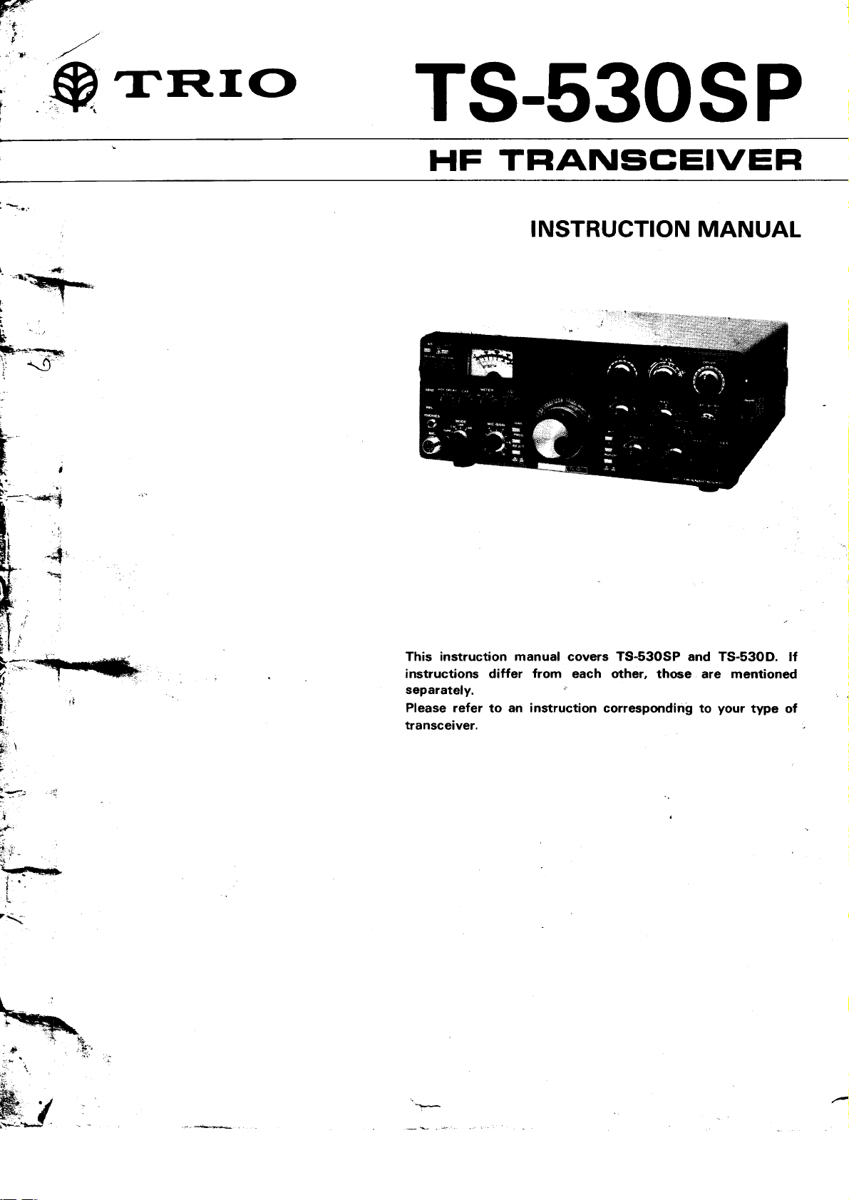
TS-530SP
HF
TFIANSCEIVEFI
INSTRUCTION
MANUAL
This instruction manual
instructions differ from each other,
separately.
Please refer
transceiver.
an instruction
to
covers
TS-S3OSP and
corresponding to
TS-S3OD. lf
thoae are mentioned
your
type of
Page 2
AFTER
Save the
needs
ance,
The following
sure to read
UNPACKING
original
to be transported
or service.
explicit definitions
these definitions:
NOTE:
lf disregarded,
inconvenience
alinjury.
CAUTION:
Equipment
damage may
packing
boxes
for
occur. but not
in
remote
apply in
-
only
personal
the
operation, mainten-
no
damage
your
event
this manual.
person-
or
injury.
CONTENTS
unit
Be
WARNING:
Personal
CAUTIoN:
Read
servrce.
WARNINC
HIGH
injury
Operating Manual
VOLTAGES
may
occur - do
PRESENT.
not disregard.
Section 4. before
placing
.@__-
trd|3rnrner ,n
SPEC|FICAT|ONS...........
SECTION 1. INTRODUCTION
SECTfON 2.
2.1
2.2
2.3
2.4
2.5
2.6
2.7
2.8
SECTION 3.
3.1 FrontPanel
3.2 Rear Panel
SECTION 4.
4.1
4.2
f NSTALIAT|ON...........
Unpacking
Operating Location
Cabling
Microphone
Key
External
speaker
and
Ground
Antenna
CONTROLS
OPERATION ............. .........
Reception
(1)
Basic Procedures
(2)
WWV Reception
Reception(ll)
(1)
NOTCH CONTROL
(2)
RFATTSwitch
(3)
RFGainControl
(4)
AGC
(5)
RrT/XrT
(6)
rF
Shift
(7)
NARROW
(8)
Noise Blanker
AND
(l)
(Automatic
Switch
(NB)
AND FEATURES........
Headphones
THEIR FUNCTIONS.
14
for Receive
Gain Control)
Operation
3 4.3 Transmission
4
5 4.4 Transmission
sEcrtoN
8
SECTION6.
SECTTON 7. TROUELESHOOTTNG
BLOCKDIAGRAM...
|NTERNALV|EW.............
SCHEMATIC DIAGRAM ........................
(1)
SSB Operation
(1)
Speech
(2)
VOX
(3)
XIT
(4)
CW
4.5
Digital Display
4.6
Analog
5.
oprtoNAL AccEssoRtEs............
5.1
Optional Accessories
5.2 Installation
MAINTENANcEANDALIGNMENT....2S
6.1
General
6.2
Service
6.3 Receiver
6.4 Transmitter
Transmitting
6.5
6.6 Operation
(t)
(il)
processor
(Voice
Operated Transmit)
(Transmitter
Operation
Dial calibration
of
Position
Adjustments
Adjustments
on WARC BANDS
on22OY ACoT24OVAC(USA)
Incremental
Calibration
Accessories
........................
Operatron
Tuning)
.......
........
...........29
20
28
30
31
el
Page 3

[GENERAL]
Frequency
Modes.........
Frequency Stability
Power Requirement
Power
Dimensions
Weight........
Range..........
Consumption
TS-53O SPECIFICATIONS
'-
2.0 MHz
1.8
-
4.0
-
7.3 MHz
MHzWWV)
-
29.7 MHz
the first
(with
(5.3)x
lbs)
MHz
5 MHz
-
18.168
.45 MHz
heaters off)
333
MHz
MHz
MHz
hour after
minute
50/60
(13.3)
period
Hz
mm
......
...................
..................
160 m
Band
8O m Band 3.5
40 m Band 7.0
30 m Band
20 m Band
17 m Band 18.068
1 5 m
12 m
1O m Band 28.O
SSB/CW
Within
Within 100 Hz during any 30
1 1
0VAC/1
Transmit:
Receive:
(13.3)x
333
12.8 kg
10.1 - 10.1
(1O.0
14.O - 14.35
21 .O - 21
Band
24.89 - 24.99
Band
'l
kHz during
20VAC|240VAC,
295 watts
27 watts
133
(28.2
1 minute of
thereafter.
(inch)
warmup.
[TRANSMITTER]
*
FinalPower
Audio
RF
Output
Carrier Suppression
Sideband
Spurious
Harmonic
Audio Freq. Response..............
Input
ALC
Linear Amp
Input.........
lmpedance
Input
lmpedance..
Suppression
Radiation....
Radiation
Relay Contact
............
Ratin9..........
IRECETVERI
Receiver Sensitivity
lmage Ratio............
lF Rejection
Receiver
Selectivity
ssB/cw.....
Notch-filter
Audio
Audio Output
Attenuation
Output
NOTE:
lmpedance
The circuit and
technology.
ratings
TS_530SP
22OW PEP
18OW DC
500p - 50
-
50Q
Better than
Better
Better than 60
Better than
4OO to 2,600
-1OV
for
for
kjz
75r/
40 dB
than 50 dB
dB
40 dB
Hz.
DC Max
CW operation
100v Dc 1A
O.25
Better than 6O
Better than 70 dB
2.4kHz
CW Optional
SSB Optional
Better than
8
1.5W
may be changed
at 10 dB S
uV
dB
(-6
dB),
Filter
YK-88C 5OO
YK-88CN
YK-88SN 1.8
-
16(2
27O Hz
Filter
20 dB
(8l2)
Hz
__
operation
SSB
-6
within
+ N/N
4.2kHz
(-6
kHz
(1
without notice due
(-60
dB),
(-6
dB),
(-6
dB),3.3
.5 kHz)
dB
dB)
1.5 kHz
1.1 kHz
kHz
160W
13OW
(-60
dB)
(-60
dB)
(-60
dB)
to developments
TS-53OD
PEP for SSB
DC for CW operation
operation
Page 4
SECTION
1. INTRODUCTION AND
FEATURES
1.1 KENWOOD
TS-530 is highly sophisticated solid
The
transceiver
band
Operating
MHz,
cludes
other transceivers.
RlT, RF attenuator,
TS-530 also
matic level control
a
speech
Any
operated
Please read all of
your
1.2
1. Interference-free
*
'
*
2. WARC
on all
this unit is constructed
many built-in
processor,
complicated electronic
incorrectly.
TS-530 on the air.
FEATURES
TUNABLE NOTCH
Interference is
notch circuit.
lF shift circuit
The lF
without changing
terference or adjusts
as desired.
NARROW/WIDE
filters for
CW operation can
optional
YK-88C
NARROW
when using
The TS-53O
bands,
MHz. The
245
below
each
digital
ternal
below each
TS-530
employing only three
Amateur bands between
modularly.
features usually found as
Included
and an effective
includes
SHIFT
enhanced
filters:
bands
including
automatic
(ALC),
speaker and
and
the operating instructions
DX operation
reduced or eliminated using
The TS-53O uses an
is a circuit to shift lF
BAND
(5OO
Hz) or YK-88CN
WIDE SSB operation
or
the optionalYK-88SN
fully covers
the new WARC
VFO covers at
50O kHz band.
VFO covers about
for
band,
are
semi-break-in CW
device will be
this transceiver
FILTER
receive frequency.
receive frequency
WIDTH selection and optional
operation.
be selected when using one of
MARS and
built-in AC
The optional
state Amateur
vacuum tubes.
1.8
The TS-530 in-
VOX. 25 kHz calibrator,
noise blanker.
gain
control
NARROW or
l27O
the 16O-1Om
bands of
least 5O kHz above
1OO
other applications.
(AGC),
with sidetone,
power
is no exception.
before
Audio notch filter.
pass-bandwidth
lt
eliminates
characteristic
Hzl
can be selected
(1.8
kHzlfilter.
VFO-230 ex-
kHz
29.7
and
extras on
The
auto-
supply.
damaged if
putting
the built-in
in-
WIDE
two
Amateur
18
1O.
and
and
and
above
All-in-one, compact
3.
4. Advanced circuit design
characteristics. Cleverly
components and
lent two-signal characteristics.
blocking are
TX final unit uses 61468's/S2OO1A.
5.
The final transmitting tubes are:
6146B's, 61468's/S2OO/AS
A for the TS-530D.
S2OO1
Amplified
duced cross
Variable
6.
Conventional
less
weak signals
This
the optimum
fier.
7. The
level
audio
XIT
8.
of
quency.
9. Built-in
Displays
any band or
1O. The controls are arranged on
panel
1 1 . A full
The TS-530 includes:
VOX circuit
cuit, side-tone
SLOW)
Tune
switch, and built-in
ALC
level noise
than effective
variable level
speech
(Transmit
transmit
processor
ALC time constant
and
level and transmit
digital display
accurate
mode.
for
easy operation.
variety
RF Attenuator.
position),
AC Power supply.
for improved two-signal
designed
receive circuit system assure excel-
reduced.
provides
modulation.
fixed
rejecting
or
threshold
lncremental Tuning) for
frequency independent of
of accessory
(available
oscillator, selectable
clear, strong signals
blanker
level noise
in removing
strong
noise blanker
level of the
controls the audio compression
power.
frequencies to the
circuits are
for Semi-Break
CW
HEATER switch. SCREEN GRID
speaker.
front-end circuit
Cross-modulation
two 61468's two
for the TS-530SP; on
blankers are
pulsating
interference
is equipped
pulse
gate
to increase the average
fine
receive fre-
1OO Hz order,
the zinc
zero-beat circuit
die-cast front
provided:
in), Marker cir-
(OFF.
AGC
and
re-
with
sometimes
noise over
signals.
to control
ampli-
adjustment
FAST,
(in
the
Page 5
2.1
UNPACKING
Remove
ing material
equipment has been damaged
portation
packing
The following
tranceiver.
the TS-530
company immediately.
material
1 . Instruction
2. Plastic
(JO2-0049-14)
3. Speaker Plug 1/8"
4. 7P
5. Fuse
Extension Feet
DIN Plug
TS-S3OSP
from its
and examine it
for future
accessories
Manual
.........
(E07-0751
(USA)
shipping or moving.
should
(850-4076-OO)
with
(E1
2-OO01-05)
TS-53OSP
TS-53OSP
TS-530D
2.2
OPERATING
As
with any solid
should be kept from
Choose
operating the transceiver
least 3 inches
ment
flow
CAUTION:
Do not operate the radio
Receiver
an operating location
to
any object. This
from the ventilating
damage may
LOCATION
state electronic
extremes
in
clearance
between
space
fan
in an RF Field
occur.
direct sunlight.
to keep the
SECTION
shipping container
for visible damage.
in
shipment, notify the
Save the boxes
included
be
....................
Screws
.....................
-O5)
12OV
220/240V
120l22OV
11Ol22OV
equipment,
of
that is
allows
64............. 1
...............
44
6/4A... 1
6/4A... 1
heat and humiditv.
dry and
the back of
cool, and
Also, allow
an adequate
transceiver
greater
2. INSTALLATION
pack-
and
lf
trans-
with the
..............
..........
each
each
the TS-53O
avoid
the equip-
cool.
than
6V RF.
the
and
1
2
1
1
1
air
at
r POWER
Make
off, the stand-by switch is in the REC
voltage
line
source.
r AC POWER
CONNECTIONS
sure the POWER
is correct. Then
switch on the front
connect the POWER
TS-530SP
For
fixed station operation, the
(U.S.A.)
AC
power
source capable
120V
.
A 64 fuse is used.
you
lf
necessary to change the
tions
and the
page
See
12O|22OV AC line
.
This version is
on the rear
and use the correct fuse. 1 20V
fuse. 22OV
. 22O|24OV AC line
This
destination type is
tor switch on the rear
A 44
fuse should be used.
Set the switch to
fuse.
NOTE:
o The 22O|24OV AC
o The 12O|22OV AC
22OV AC|24OV AC
or
of supplying 280 watts
AC line model
desire operation
27.
panel.
setting
(U.S.A.)
fuse.
model
equipped with a voltage
Set
requires
model
oanel.
your
model is
model is
unit operates from
on 22OV
power
the
switch to
a 44 fuse.
(Europe)
equipped with a voltage
line voltage
preset
preset
panel
is turned
position,
(Europe),
AC
transformer
setting requires
and use the correct
to 22OY.
to 22OV.
and the line
cord to the
5O/6O Hz
or
or 24OV
selector
your
line
120V
more.
AC, it is
connec-
switch
voltage
selec-
a 6,4
2.3 CABLING
r GROUND
prevent
To
and
electric shock,
BCl,
connect the transceiver
through as short
rods or metal
NOTE:
ground
A
transceiver may
ground.
r ANTENNA
Connect through
ial connector
I KEY
lf
CW operation is
Use
shielded line
cold water feedline.
connection
on the rear
(See
Figure
2-1.)
and reduce the
heavy
and
be a
a 50 ohm
desired, connect
or coaxial cable.
a lead
greater
than 1/4
good
DC
antenna feedline to the
panel.
possivility
good
to
a
possible.
as
ground,
a key to the KEY
earth
Use
away from the
).
but NOT
TVI
of
ground
ground
an RF
coax-
jack.
For fixed
22OV AC,50/60 Hz
Check
The 1 1OVAC
The 22OVAC
Note:
The TS-530D
station operation, the unit
your
local
line voltage
setting requires
setting requires 44 fuse.
preset
is
TS-530D
powersource.
before operation.
fuse.
64
to 1 10V
AC.
operates
either
1 1O
or
Page 6
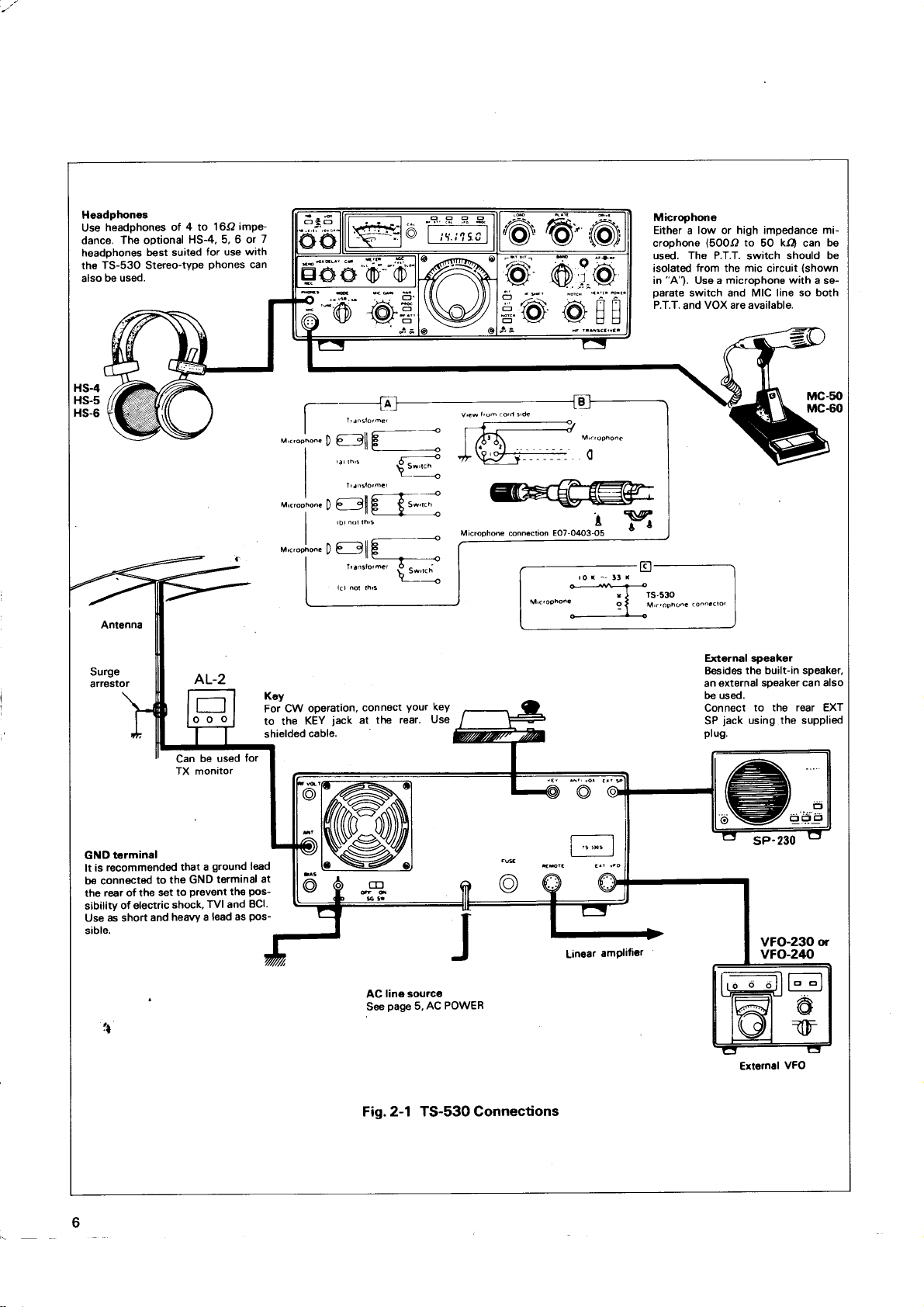
Headphones
headphones
Use
The optional
dance.
headphones
TS-53O
th€
be used.
also
Antenna
Surge
arrestor
of 4 to
HS-4,
best suited
Stereo-type
AL-2
Can
TX monitor
16O
5, 6 or
for use
phones
be used
imPe-
with
can
for
7
M'c'ooho.c
M,c,oeho..
Key
For CW
to the
shielded
,-<
n t--all E
r-
'^-ll
l) P 9[
,--ll
|
^-tt 6-<
e____9ll
u
| -
I'ansto'mc'
I
tack
connect
at the
operation,
KEY
cable.
E
trq
O.
--'
t-::
\
Your
rear.
o
keY
Use
Microphone
Either a low or high impedance microphone
used. The P.T.T.
isolated
in
oarate
P.T.T.
(5OOO
to
kO
50
from
"A").
Use a
switch and MIC line so both
and
switch
mic
th6
circuit
microphone with
VOX are available.
External speaker
the built-in speaker,
B€sides
external sDeaker
an
be used.
Connect
SP
ptu9.
to the rear EXT
jack
using
the
can
should be
(shown
a se-
MC-50
MC-60
can also
supplied
be
terminal
Gl{D
recommend€d
is
It
b€ conn€cted
rear of the
the
of electric
sibility
as short
Use
sible.
6
to
set to
and
that a
the GND
prevent
TVI and
shock,
heavy a
ground
terminal
the
lead as
lead
pos-
BCl.
Pos-
sP-230
at
EI
line source
AC
page
See
AC POWER
5,
Linear
amPlifier
VFO-23O
vFo-2tto
Extemal
or
VFO
Fig. 2-1 TS-530 Connections
Page 7
2.4 MICROPHONE
Attach the
phone,
PTT switch
shown.
plug
using a
The microphone
crophones.
good
tion.
the restriction
restriction
portant
throughout
Follow the
connecting
microphones,
make microphone
unwanted
the microphone
ing
contacts
Standard
-50
sitivity
function
tenuator
setting
clock
microphone
as shown
lt
should
speech
The
crystal
in the
have a
to
feature
which control
microphone
to
dB
is used,
properly.
as shown
is 1 2 o'clock.
less, use an attenuator.
or
in Figure
is separate
be
common
input
choice of
The
quality,
the speech
microohone
the
-60
and should
lattice
necessary
microphone
microphone
microphone
push-to-talk
the
audio
may be eliminated,
case
dB.
ALC
the
In this case,
in Fig.
2.5 KEY
lf
CW
Use
plug.
operation
shielded
is desired,
cable, and
connector
2-1 . Be sure
from the microphone
noted that
ground
lf a
terminal
is designed
microphone
filter in
on audio
is
range.
manufacturer's
cable to
available.
and
the microphone
sensitivity
microphone
and
2-1c. A typical
you
lf
must
connect
a standard
to a suitable
a microphone
should
for 50OO
given
be
the transceiver
response,
required.
not
with a smooth,
the
switch
permanently
compressor
insert
must
VOX operation,
For
if. desired,
audio.
is within
having a
in the
run this control
a key
(mono
micro-
microphone
the
circuit, as
with a 3P
not be used.
-
is important
serious considera-
provides
and
is more im-
lt
flat response
instructions
plug.
With many
be
connecting
the range
higher sen-
circuits
mike line an at-
gain
MIC
to the KEY
or
mi-
50kO
for
further
for
pressed
this
by open-
the
will
not
control
at I o'-
jack.
phone
2P)
all
to
of
2.6 EXTERNAL
HEADPHONES
Receive
16 ohms.
rear
magnet
disconnected
phones
greater.
panel
audio output
The TS-530
panel.
The speaker
type,
should
When
PHONES
4 inches
when an external
also
headphones
jack,
2.7 GROUND
To
orevent
and
through
2.8
Any of
the high
TS-530
line
network.
An antenna
less than 2:1
sion
put
15
and
with
mission
tuner
and
such
Handbook, and
160, 75 and
resonance
to
perform
the
tion
antenna
transceiver
CAUTION:
Protect
The TRIO
electric shock,
BCl, connect
as short and
ANTENNA
the common
frequency amateur
provided
is
outside
not
The transmission
system
when
line, or a system
impedance
2OO ohms
little difficulty.
line is used
with balun
feedline.
the
tuners are described
10, 15 and
will be
your
that is essentially
is recommended
similar
4O meter
in the
satisfactorily.
20
greatly
is used. Remember
is useless
Equipment-Use
AL-2 is
SPEAKER
from the
has a built-in
or'larger.
be
the speaker
transceiver
the
heavy a
antenna
input
the
the capability
which
using
that
will take
openwire of
lf
with the antenna,
Methods
publications. For operation
bands, a simple
most used
For operation
meter bands, the
increased
without
recommended.
AND
TS-530 is
speaker
may be
4 to
and
impgdance
shows a standing
5O or
results in a
in detail
an 8-ohm
internal speaker
The
speaker
'l
ohms
6
connected
are
is disabled.
reduce
lead as
systems
bands
line should
power
of
that even
a
the
good
to a
possible.
designed
may be used
of the transmission
the bi-output
of
75 ohm coaxial
transmission
resistive, and between
from the
balanced
between
construction
in the ARRL
portion
of
efficiency
good
if a
proper
antenna.
LIGHTING
a
1.5 watts at
jack
permanent-
is used.
impedance
to
possibility
earth
be coaxial
wave
a suitable
the
and operating
dipole antenna,
the bands,
of
the transceiver
directional
most
the
ARRESTOR.
4 to
the
on
Head-
the front-
TVI
of
ground
for use on
with the
m3tching
cable.
ratio of
transmis-
line
transceiver
trans-
type
antenna
transceiver
Antenna
on the
cut
will
the sta-
of
rotary
powerful
is
or
in-
on
Page 8

SECTION
3. CONTROLS
AND THEIR
FUNCTIONS
ruorcu rNcrcAToR
@
rnotcnroR
@vro
rNDrcAToR LED
enoc
@
nr arr rNDrcAToR LED
@
cnl
swrrcu
@
@ueren
swrcn
@vox
eru
@vox
@r.rsswtrcn
rue level corurnol
@
swrrcn
@lcc
leo
LED
DIGITAL DISPLAY
ANALOG DIAL SCALE
MAIN TUNING
LOAD CONTROL
CONTROL
PLATE
DRIVE
RIT/XIT
RIT/XIT
@enruo
+ 0.5 SWITCH
C)
O
CONTROL
LED
CONTROL
swrrcH
@rueren
@srnruo-av
@vox
@
@eHones.llcr
@vrrc
@uoor
@
swrrcH
swtrcH
oruv
lrvel coNrRoL
can
cor.rruecron
swrrcH
utc clr.r coNTRoL
@ruan
o
O
IF
CONTROL
SHIFT
@ruorcu
/rrcH
s\
@
@enocswrcu
@nrarr
swrcn
6r
Fig.3-1 Front
Panel View
xrT swlTcH
RrT
SWTTCH
o
@
Page 9
FRONT PANEL
3.1
The symbol after the
Active
@:
Active only during transmission.
@:
No
symbol:
1. NOTCH TNDTCATOR LED
This indicator,
NOTCH circuit
2. VFO INDICATOR
The VFO indicator illuminates
trols transceiver operation.
during fixed channel or
(SPEECH
PROC
3.
indicator,
This
PROC switch is turned ON.
4. RF
ATT TNDTCATOR
This illuminates when the RF ATT is turned
s. cAL swrTcH
This
switch energizes
Receive
using this oscillator.
6.
The meter monitors five different
METER
cally an S-meter, and shows
scale of O to
depends on the
scribed below.
peak.reading.
7. VOXSWTTCH
The VOX
SSB or
frequency
METER
switch
circuit
semi-break-in CW.
part
name indicates:
only during
Always
(light
emitting diode).
is
tumed ON.
remote
PROCESSOR)
(light
emitting diode), illuminates when
reception.
active
@
illuminates
when the internal VFO con-
The
indicator is not lighted
VFO
operation.
TNDTCATOR
@
(R)
the
built-in marker circuit.
can be calibrated at 25 kHz intervals
functions, depending on
position.
4O
dB over 59.
position
This is
is
In receive
received
In
the METER
of
an average-responding meter, NOT
O
readied
for voice
meter
the
signal strength on a
transmit, meter function
operated
when the
O
ON.
is automati-
switch, as
transmit in
the
de-
10. NBLEVELCONTROL@
This
control adjusts the
level
according
11. AGC
This controls the
OFF.............. AGC disabled
FAST
SlOW..........
12. METER SWITCH
Thb
ALC
SWTTCH
...........
determines the
(Automatic
Monitors intemal ALC
fuedback
tion
reading
ALC range. ALC voltage adjustment is made with
ed
MIC
the
recoiving
to
@
AGC
Normally
Normally used
transmit meter
Level Control)
from a linear
with the TS-53O. For
for voice
control
noise
conditions or noise level.
(Automatic
used
peaks
for
SSB and
cw.
(Plate
lP
RF
HV
13.
This
REC......'.'..... The
SEND
Current)
Power)
There
the
Vohage)
position
The meter
.'...'....'
position
The
crophone
activatd.
Locks
th€ mster monitors final tube
is calibrated from O to
scale
meter
is no
reading
lOOOvohs.
should be adjusted
monitors the high voltage
is calibrabd from O to 10, indi-
scale
lever
switch selects:
transceiver
PTT
the unit
In this
current.
(Output
This monitors relative
ceiver.
mally
METER control)for a 2/3 scale
(High
This
ply.
catingOto
STAND-BYSWITCHC)
two-position
blanker circuit
Gain Control) circuit:
(no
AGC).
for
CW operation.
for
SSB operation.
function:
voltage,
amplifier
should be within the indicat-
output
is receiving
switch, or the
in transmit.
or the ALC
operated in
SSB operation the
with the CAR
power
for
scale
this
reading.
operation
voltage
conjunc-
control
ma.
350
of the transposition.
(with
the RF
pq,ver
the mi-
unless
VOX
circuit
ALC
plate
Nor-
suf
is
for
VOX
8.
This controls
Transmit) circuit.
9. NB
With the
ON reducing
QRM and atmospheric
blanker.
table by the noise blanker
GA|N
O
sensitivity of the
SWTTCH
push
switch
pulse-type
The noise
@
lN, the
(ignition)
"white"
blanker circuit operating level
(Voice
VOX
noise blanker circuit turned
noise. Power-line, radat
noises will not operate the
control.
Operated
is
adjus-
14. VOXDEIAYCONTROLO
The DELAY
break-in CW
15.
CARLEVELCONTROLC)
This
controls canier
CAR level so that the ALC meter
ALC zone.
zone.
control adjusts
operation.
level during CW
The
ALC
meter
Adjust for individual
the hold time for VOX or
should not
preference.
operation.
points
to the center of the
read
beyond the
Adjust the
ALC
Page 10
PHONESJACKG)
16.
jack
headphones
The
greater
phones
17. MrC CONNECTOR
The
PTT
18.
The mode switch
TUNE'.........'.
CW
USB
LSB...............
19.
This
operation.
peaks.
20.
With optional
lected by
filters
page
21.
This switch
to the ON
ated,
22.
With
serted
and
headphone
used
are
pin
four
Figure
MODE
..'............
..............
MrC GA|N
control adjusts
NAR
1 6.
PROC
increasing
RF ATTSWITCH
mixer
connector
2-1 B shows
SWITCH
This
shorted
put power
prevent
this
signal.
Used
Used
national
of USB
Selects
teur
below
Adjust
SWITCH
filters
the Narrow
being used.
(SPEECH
is
used
position
this switch
in the antenna
from overload
allows use
through a
the speaker
selects
position
key line
tube
position
for CW operation.
for upper-sideband
Amateur
on and above
lower-sideband.
practice
the
CONTROLO
microphone
for an on-scale
@
installed,
Switch.
For details,
PROCESSORISWITCH
during SSB
the
and
the average
@
ON,
circuit,
of a
1/4"
is disconnected.
O
allows
plug
use of
(Page
wiring.
emission,
type of
provides
for transceiver
the final section
to
damage during
to zero-beat
practice
the 1
dictates
7 MHz band.
speech
talk
A
on strong
the
amplifier
ALC reading on
the lF bandwidth
The
bandwidth
refer to
operation. Set
processor
power.
20 dB attenuator
protecting
input signals.
4 to 16 ohm
phone
plug.
a microphone
6)
TUNE.
and
reduced
International
Narrow Switch
carrier
tuning.
is reduced
tune-up.)
incoming
an
operation.
dictates
4 MHz band.
use of
the
the
LSB on and
gain
for
can
varies
O
the
will be activ-
RF amplifier
or
When
with
and
(ln-
to
Use
CW
Inter-
use
Ama-
SSB
voice
be se-
with
on
switch
is in-
23. DIGITAL
The digital display
nearest
24. ANALOG
The mono-scale
over the
Opeating
switch
above and
MAIN TUNING
25.
This
controls
ing frequency.
tunig.
LOADCONTROLO)
26.
This controls
section
4.
tion
27. PATECONTROL€)
This controls
bration
28. DRIVE
This control
driver as
receive
(maximum
mum
ON-SCALE
rently.
29. RITD(IT
This indicator
is ON.
RITD(IT CONTRL
30.
This control
quency
control.
ed to shift
With the
the transmit
only
When both
The
ed.
DISPLAY
indicates
Hz.
1OO
DIALSCALE
permits
range,
O to 5OO
frequency equals
frequency
and
is
approximate.
well as
the DRIVE
Tuning for one also
or
With the
XIT switch ON.
center
kHz
(in
MHz).
the 5OO
below
the VFO,
The indented
the loading
the antenna.
plate
the
CONTROL
the
tunes
receiver's antenna
the
control
S-meter
both to be shifted
only
deflection), and
reading.
ALC
INDICATOR
light when the
will
allows
switches
the
RIT
switch
the receive
frequency.
are ON,
(O) position
operating
analog
direct
graduated
(in
kHz)
dial
the
An
additional
range is also covered.
kHz
selecting
of
Adjustment
tuning of
plate
is tuned
receive frequency,
the
the transceiver's
is convenient
knob
the network
final amplifiers.
the
tank circuit
for maximum sensitivity
in transmit
points
These
RIT switch
the
ON,
both
no shift.
the other.
RIT circuit
frequencies
achieves
without using
frequency.
XIT circuit
equals
is described
frequency to the
frequency
1-kHz intervals.
at
between
of the
and
the
is activated
readout
plus
mixer coils.
BAND
the
5O kHz
operat-
quick
for
the final
in
Y 7A
12 B
maxi-
for a
concur-
occur
XIT
or
switch
transmit
main tuning
is activat-
to shift
are shift-
both
Sec-
Cali-
ln
fre-
10
Page 11
BANDSWITCH
31.
1O-position switch
The
1.8 to 29J
pushthe+O.5switchON.
Use the
+0.5
32.
This switch
Depress the
the transceiver
When the bandswitch
operate
tion at any
AF GAIN
33.
This adjusts
wrse.
RF GAIN
34.
This adjusts
for maximum
wise
POWER SWITCH
35.
This switches
MHz.
10 MHz band
SWITCH
is used
switch
will
29.5 MHz band.
in the
other bandswitch
@
receiver audio
@
receiver RF amplifier
power
all
selects all
To
select
for \iy'WV
in conjunction with
with the
operate in
is set to
gain
and a correct S-meter
to the transceiver.
IFSHIFTCONTROL@
38.
Amateur bands
the 28.5 or
reception.
bandswitch
"29",
This switch
position. Tuning) circuit and
level. Volume
29.5 MHz band,
the bandswitch.
set to
the 28.5 MHz
the transceiver
has no func-
increases clock-
gain.
Turn fully clock-
from During
"28",
band.
reading.
crystal
ment of tone
nearby
center
39.
and
will 40. XIT
This
This
control, the
without
41.
This
Tuning)circuit,
control,
without changing
lf, both switches
quencies
reception,
filter can
frequencies.
position (click
detent
NOTCH SWITCH
controlsthe
switch
SWITCH
push
switch activates
VFO transmit
changing
RIT SWITCH
push
switch
the VFO
will shift simultaneously.
the
effective
be shifted
quality,
For normal operation,
@
O
XIT indicator.
the
receive
the
@
activates
the RIT
and
receive frequency
the transmit
are ON,
center
-r1.2
or eliminating
stop).
NOTCH circuit
the XIT
frequency
frequency.
the
indicator.
frequency.
both the
frequency of the
facilitating
kHz
interference from
and
(Transmit
By adjusting
be varied
can
(Receiver
RIT
By
adjusting
can be
transmit and
set
indicator
Incremental
-r
Incremental
+
varied
receive f
lF
adjust-
to the
the XIT
kHz
2
RIT
the
2
kHz,
re-
HEATER SWITCH
36.
This
switch
turns
oN.
NOTCHCONTROL@
37.
Turn the NOTCH
Adjust
ence) signals.
the notch
the three
switch ON
frequency to
transmitting
to activate
null beat
filaments
tube
the notch
(carrier
interfer-
filter.
11
Page 12

cooltruc
@
nrvolrcoNrRoLc)
@
rnru
VOX
ANT|
.SPEAKER
KEY JACK
CONTROL
JACK
O
O
@
arurrrurun
@
arns coNrRoL
@
luc
cr.ro
@
swrcx
sc
@
nc eowrn
@
coNNEcroR
cnau
Fig.3-2
Rear
Panel View
AC
VFO
FUSE
xolrs
EXTERNAL
CONNECTOR
neuorecoNNEcroR
@
eneontleo
@
REAR PANEL
3.2
1. COOLTNG
This fan cools the
efficient operation.
and
FAN
O
RF
amplifier
2. RFMETERCONTROL€)
This adjusts the
reading
scale
ANTENNACONNECTOR
3.
This
SO-239
table 50O antenna
BIAS
4.
CONTROLO
This adjusts the bias
plifier
tubes. Clockwise
current. Section
RF
output
CW transmission.
during
coax connector
transmitting
for
voltage to the transmitting
rotation
4 describes
adjustment
12
section to insure
reading.
meter
Set
should be attached
receiving.
and
increases the idling
to 60 ma.
reliable
for 2/3
to
a sui-
final am-
plate
5. GND
To
nect the transceiver to a
6. SG SWTTCH
This slide switch controls
final tubes.
mains
(GROUND)LUG
prevent
electric shock, as well as
For
for normal
ON
good
O
the
neutralizing,
switch OFF.
operation.
earth
screen
RF1
ground.
grid
7. AC POWER CABLE
This
cable
is
used to
connect
an
AC
power
transceiver.
8. KEYJACKO
Using shielded line, connect a
key to this 1/4"
for CW operation. Key open-terminal
-
mately
65V.
BC1, con-
and
voltage to the
The
switch
source
phone
re-
to the
jack
voltage is approxi-
Page 13

ANTTVOXCONTROLO
9.
Adjust the control to
vox.
the
10.
SPEAKERJACK@
The receiver
jack
to
audio output can be
an external 4 to 1 6 ohm
prevent
speaker output from tripping
speaker is disconnected when
nected.
1 1. EXTERNAL VFO
This DIN
or VFO-240
provided
12. REMOTECONNECTOR
This connector
other accessory
connector is used to interface the TRIO VFO-230
external
with
the VFO.
PIN
1
VFO signal
2
Relay control
(+
on transmit)
+9V
3
4
CW freq. shift control
CONNECTOR
VFO. The
FUNCTION
is used to interconnect a
See
page
item.
connected through this
speaker.
The internal
an external speaker is con-
interconnecting cable is
PIN FUNCTION
5
VFO control
6
Display control
7
Ground
8
+12Y
linear
24 for detail.
amplifier
or
AC FUSE
13.
This fuse
short circuits.
cified;
fuse blows,
For
22Ol24O
14. PREDRILLED
These are
nectors.
*
VOLTAGE SELECTOR
The 22Ol24O
(TS-53OSP:
switch
voltage, as required.
protects
it will eventually cause
try to determine
11O1120
volt operation, a
provided
for Europe)
on the
the transmitter
Never use a higher amperage
volt
operation
HOLES
for
VAC or
panel.
rear
power
extensive damage.
the cause before
use a 6 ampere
4 ampere fuse.
owner-installed
SWITCH
12Ol22O
is equipped
this switch for
Set
VAC line model
with a voltage selector
supply against
fuse than spe-
replacing.
fuse and for
switches or
your
local line
lf the
con-
13
Page 14

SECTION
4. OPERATION
SSB
SLOW
reception:
CW
recePtion
Setting
for recePtion
(A)
Set
BAND
Fig.4-1
to desired
FullY
AF
counter-
clockwise
Control
or
USB
TUNE
Use
when
and Switch
Setting
LSB
posation
tuntng
Settings
for transmission
oo
':
Setting
@
n
(9
o
!
(A)
Adjust for
RF
max
for transmission
r
rr
ON
Sct
desired
BAND
{B)
to
fa))
RECEPTION
4.1
NOTE:
the MIC
Set
dental
TS-530
dummy
or
length
and
transmission
must be
load
wire antennas
used.
Conventional
be
only
should
Exceeding
the
of
an SWR
transceiver.
Adjust
(l)
controls
CAR
before
operated
with an
light-bulb
or
half-wave
or
at
used
2'. 1 can
of
control
DRIVE
Fig.4-2
minimum
to
tune-up
50 ohm
into
than
less
SWR
dummy
dipoles
near
and
their
damage
maximum
for
Drive Control
(Preselector)
prevent
to
is completed'
-
75 ohm
2
loads
beam
resonant
antenna
1' Random
:
cannot
antennas
frequency'
the output
deflection.
Adjustment
acci-
The
be
stage
(1)
Basic
Procedures
With a suitable
the transceiver,
to
POWER
the
Turn
indicator
VFO
Advance
ating.
receiver
ing dial
chosen
reception,
S-meter
(2)
WWV
the
Set
1O.O
to
trol
RECEPTIN
4.2
section
This
provide
(1)
NOTCH
single
lf a
receive
the
NOTCH
of approximately
beat
center
tween
will
is
noise
within
signal
a
until
then adjust
and
deflection.
RecePtion
switch
band
MHz.
covers
maximum
CONTROL
tone
signal,
control
position
and
35O
Receive
for
microphone
antenna
the
the
and
the controls
set
switch
indicating
light,
AF GAIN
in the speaker.
heard
frequency
ON.
is heard.
the
(Fig.
4-2l.
"10"
to
and
(ll)
operation
performance from
CW signal
a
as
such
the
turn
to eliminate
or
14OO
control'
the
of
Hz.
260O
Operation
as
The
the
control
range
Tune
DRIVE
turn
controls
of
NOTCH
minimize
Hz can
NOTCH
The
key connected
or
4-1
shown
meter,
clockwise
of the
the
the
in Fig'
dial
transceiver
the
Turn
Amateur
for clearest
signal
control
the
for
main
and
tuning
switches
TS-530'
scale,
is
until some
main
maximum
is superimposed
and adjust
ON
signal'
beat
the
be eliminated
is effective
'
and
oper-
tun-
band
con-
to
on
the
the
at
be-
A
14
Page 15

Audio output
(NOTCH
(2)
RF ATT
The input
mately 20 dB,
feature
by a strong
either
when a strong
tion
pump
or
(3)
RF
GAIN
RF
GAIN
Adjust the
tage.
excessively.
normal operation.
for maximum
wise
OFF}
Fig.4-3 Notch Control
SWITCH
to the receive
providing
may be used
noise blanker.
the
CONTROL
is
controlled
RF
This also
Receive
signal
RF amplifier
in cases
signal, or during
local
adjacent
by changing
GAIN
reduces noise during
this control should
sensitivity.
lnterfering
signal attenuated
NOTCH
by
distortion-free
of receiver overload,
may blank the
signal
the AGC threshold
so the S-meter
\t./
Au-dlo-outPut
(NOTCH
is attenuated
be
ON)
reception.
weak
signal
does
reception.
turned
not deflect
fully
Receive
signal
approxi-
This
caused
recep-
receiver
vol-
For
clock-
(s)
Rrr/xrT
RIT/XIT control
First set
switch ON.
The RIT/XIT
by approximately
frequency.
With the
adjusted
With
and receive
For XIT switch
sion
ttn?E.
When
the
switch OFF.
(6)
The lF SHIFT
filter without
control
shown
The lF SHIFT
the
during operation
the
control allows
RIT switch ON,
by using
both the
(ll)".
the RIT
receive
IF SHIFT
receive signal
RIT and
frequencies
is
frequency.
lt
should
control
changing
in either
4-3.
in Fig.
is effective
operation,
in both SSB
to center, and
-r2
the RIT control.
ON,
direction,
is superimposed
shifting
kHz without changing
receive
the
XIT switches
be shifted.
can
refer to Section
transmit
For normal
be turned ON
is used
frequency
operation,
to shift
receive
frequency.
the lF
in eliminating
or CW
turn the
the receive
frequency can be
ON, both
when needed.
only
passband
the
passband
interference
on nearby signals
mode.
frequency
the
the transmit
"Transmis-
4.4
is
different
leave the
By turning this
is shifted as
RIT
transmit
from
RIT
the lF
of
when
"S"
Maximum
ot an incoming
Signals
this
than
areattenuated.
AGC
{4)
Set the
for SSB,
the AGC
Simultaneous
Switch
lf a strong
vicinity
show
from the strong
loped
RF
the
the original
This will
reception.
clear
meter
weaker
level
Fig.4-4
(AUTOMATIC
AGC switch
SLOW,
may be turned OFF.
signal
of the
unusual
down so
GAIN
deflection
eliminate
reading
signal.
Pointer deflection
gain
control
RF
Counterclockwise-
RF GAIN Control
the
to
for
CW
the RF
Use of
(such
as a local
intended
deflection
disturbing signal.
the meter
peak
the unwanted
(lEY"
\r=f
with
adjusted
.\{
€tr't
Operation
CONTROL)
GAIN
appropriate
FAST, and
GAIN
receive signal,
due to the
and
position:
for very
CONTROL
station) appears
AGC voltage
pointer
turn the
AGC voltage and
GAIN
RF
I
olo
RF GAIN
4,6
the S
lf this occurs,
remains at about
AGC switch OFF.
t
Full
clockwise
Positron
Turn
counrer-
crockwise
Generally
weak signals,
and AGC
in the
may
meter
deve-
turn
permit
in
Turned
Odirection
Interfering signal
IF
SHIFT
,--9---
dt
V
inOdirection
Turn
eli
from signal B.
min ate
interference
passband
lF filter
characteristic
IF SHIFT
--9---
o
4,Ai'
V
to
Fig.4-5 lF SHIFT
Turned inOdirection
Interfering signal
IF
/ ).-\<
o/
v
inOdirection
Turn
minate
eli
from signal
CONTROL
SHIFT
.-9---
\
[o
i nterference
A.
to
t5
Page 16

(a)
USB MODE
Adjust the lF SHIFT control in the
frequencies
and high
(b)
Adjust the
cies are
frequencies are cut.
(c)
By using the
quality
(71
In the
nals are
YK-88CN, SSB:
available for improved radio interference rejection. Any
two
When two CW filters, YK-88C and YK-88CN are used, the
WIDE
(81
For
nition systems,
LEVEL control
even
lf
quency,
may
lf
ATT
frequencies
LSB MODE
cut.
CW MODE
can be
NARROW SWTTCH
NARROW
filters
position
NOISE BLANKER
pulse
low level noises.
high level
do
distort the
you
are operating
along
(14
MHz and
are cut.
control
Adjust the control in the
received.
can
type
signal or
not
with the noise blanker level
Adjust
are cut.
(7
MHz and belowl
in the
lF
SHIFT
adjusted.
position
Optional
YK-88SN) for
be used
in
mode is
CW
(NBl
noise,
such as
turn the NB
varies the
noise is
use excessive
received
near
above)
the control in the
(+)
direction
in
conjunction with the RlT, tone
without
according
blanker's threshold, eliminating
signal.
other strong signals, use
optional
filters
NARROW operation
kHz.
O.5
generated
switch ON.
present
NB
threshold LEVEL as it
(+)
direction and
(-)
higher frequen-
and
(-)
direction and
filters no
(CW:
your
to
on an adjacent
control.
application.
by automotive ig-
Adjusting the
lower
direction
low
sig-
YK-88C,
are
NB
fre-
the
RF
Fig. 4-6 Testing with a Dummy
Power Meter
1 .
Connect a 50(2 antenna for the band
a dummy
or better. The life of
the SWR of the antenna, and
periods.
2. Turn POWER and HEATER
Place the
3.
4. Place the
6O
control on the
CAUTION:
plate
lf the
(TS-530D)
mA
more
tens the life of the final
load,
and connect a
the
MODE switch to
STAND-BY switch to SEND
(TS;S3OSP}or
mA
rear
current
do
than a few
3O mA
panel,
is higher than
not
lqave the stand-by
seconds. Excessive
tubes.
final tubes is
Switches ON.
SSB,
Fig. 4-7.
r_l
@@
Load or
you
will
operate
key.
to the length of tuning
METER switch
(TS-530D)with
mA
6O
must
SWR
directly related
and
(TS-S3OSP)
plate
be 2 :
to lp.
adjust
the BIAS
switch on
current shor-
bias to
or 30
or
1
to
for
4.3 TRANSMTSSTON
This section covers adjustment of the transceiver for
transmission.
Refer to Fig.
main
the
Table 4-1 tor a summary of the following.)
to
CAUTION:
DO NOT turn the BANDSWITCH while the transceiver is in
transmit
l6
4-1 for initial transmitter
tuning to
mode.
(r)
the desired
switch settings.
operating
frequency.
Set
(Refer
*. : * *"'i'.-.
Fq9
9,^:ffi\-
@\/
Fig.4-7
TS-530SP 6OmA
TS-530D 3OmA
nr\"" m
\z)
\y
-
-1
.=
€f
'l"
^-
MIC
Control
Fully
counterclockwise
Adjusting FinalTube
Bias
Page 17

5. Place MODE switch to TUNE. METER switch to ALC.
is
or
a
goes
out
level ad-
adjust-
Peak the DRIVE control. lf the
of the ALC range, reduce the
for
an on-scale
justment,
ment.)
Fig.4-8
reading.
while the
(the
drive control
pegs
meter
CARRIER control setting
CAR control
is a resonating
NOTE:
The TUNE
reduced
at
TUNE
approximately 5O"/o and the keying
position permits
power
position,
the screen
without
Adlust
maxrmum
tuning of the final tank
danger to the tubes
voltage
the fianls is reduced
to
is
circuit
DRIVE
meler
closed.
control for
deflectron
circuit
. In
the
For
maximum
deflectron.
--
lo.io
lloo
E.---
),Eo-o-
l"d
^ .'€." .=
^ \\ \/
\!)
-f\\
\J
I drF_
lr,,l._F9'
----t-'"'
|
l-'q
.*E,EJ
U A
A
.f\\\_r//f',,^,.
"Yf
Fig. 4-1O
Ourckly
adtust the
then the LOAD
(maxrmum
peak
_I
(o)
|
'
o
l
tg
=_
PLATE
contror
control
meter
allernately
deflectron) the
ano
to
power
ro(0,@
A
/rAS
;l
"
-JTTT
Fri \Vl \V/ L-.t t l
@
Final Tuning
"A' |.l n
\II' J(/ \'\L H H
IF IRANSCE
!!
outpu
V€R
l^\ #\
\/\1
Fig.4-8 Peaking the Drive
-lF
,A,AI
V\1
EO
Fig. 4-9
l-l!ffi\-
[\
Ch- lV\ |
\1,/
control
PLATE
Adtust
maxlmum meter defleclron
Adjustment
Plate
6. Place the
will be
typically
plate)
Fig.4-9
7. Place the
meter
meter
switch
only about 5
switch
to lp
ma.
to RF
dip the PLATE. Dip
and
(or
RF and
to
peak
and
the
peak
the
LOAD con-
trol.
Control
8. Place
Close
trol.
mA
265
the Mode switch
the key and
Reduce the
IMMEDIATELY
carrier control setting
(TS-S3OSP)
to CW,
145 mA
or
Meter
switch
redip the PLATE con-
if lp reads over
(TS-530D).
to lp.
Open
the
t(ey.
9. Place the
Close
output.
e
'"!
|
V
]
@4nN@
.a,,
-/1/
lrL'
v
'A')
5
il
lV.
5
:
.-,
i9)
i
for maximum
Open
necessary, adjust
panel
This
NOTE:
Dip
put,
meter
for
I AAdrusr,ns
t | / \
I
l_/
\-
orl
pLATE
adlusrment
pornr
ranse
For this
and the LOAD controls
scribed
4-1.
meter switch to
the key
and
You may at
RF
output.
the key.
You are tuned up for CW operation.
to bring the output
is a meter
point
because
adjustment,
may not
neutralization
band.
reason,
you
in both tune-up
RF.
repeak the
your
LOAD for maximum
option
also redip
the PLATE
Fig.4-8
the RF METER control on
reading to about 2/3 scale.
not an output adjustment.
always
coincide
is
may simply adjust
with maximum out-
accomplished
both the
on the
for maximum outout
procedure
summary
and
RF
lf
the rear
10
PLATE
as de-
Table
Table 4-1 .
MODE
USB or LSB
TUNE
TUNE
Summary
Switch
CW
Transmitter Tuning Procedure
of
METER
Switch Stand-bv Switch
IP
ALC
RF
RF
REC
REC
REC
REC
-
SEND
-
SEND
-
SEND
-
SEND
Procedure
Adjust BIAS control
mA(TS-53OD).
or30
Peak the RF reading
for 60 mA
with
the PLATE and LOAD
controls.
Peak RF output
by
alternately adjusting
PLATE and LOAD controls.
(TS-53OSP)
the
17
Page 18

(1)
Tune
the
nect
OPERATION
SSB
the TS-530 as
MODE switch
a microphone
NOTE:
International
shown
as
To operate SSB,
CARRIER
MODE
gain
MIC
peaks.
not accurate or
Amateur
in Table
control
switch
to
control
(Disregard
relevant.)
1.8 MHz Band
MHz Band
3.5
7 MHz Band
1O MHz
Band
14 MHz Band
18 MHz Band
21 MHz Band
24.5 MHz Band
28 MHz Band
TABLE
described
per
Table 4-2, to USB or
to the MIC
practice
in
input.
dictates
4-2.
connect a
microphone.
have no effect
METER switch
SSB,
for an on-scale
RF
lp meter redings
and
4-2 Mode By Band
steps
in
SSB
ALC
1 through 9. Set
LSB
and con-
(The
or LSB
Key and
using USB
mode.) Place the
ALC. Adjust
to
reading on
in
SSB-they
LSB
LSB
LSB
NO SSB
USB
USB
USB
USB
USB
the
voice
are
(11
SPEECH
In
DX
creased
The speech
compression
provide
to
output
activate.
Operated
tone
ever,
to conduct normal
able
PROCESSOR
(long
distance) operation,
talk-power
by using the speech
processor
amplifier
extra audio
power,
while suppressing
turn on
the PROC switch, and
described,
as
quality
will be affected.
in the
with changes
punch
distortion
operation
abled.
When a high-output
distortion
and
in
tor
1O
across
microphone circuit as shown
the
-
kO resistor
33
the microphone
microphone is used,
will result.
To
(depending
input.
ting should be approximately
1 Ok - 33 kO
(depending
it may
be desirable
processor.
TS-530
combines
in ALC time constant
to increase average
and
sideband
readjust mic
will be
minimum.
lt is therefore advis-
with the
processor
input overload
prevent
this, use an attenua-
below,
microphone
on
("Normal"
12
O'clock).
microphone used.)
on
mic control set-
to the MIC connecter
to in-
an audio
splatter.
gain.
How-
or
connect
used)
SSB
To
dis-
a
(Push
PTT
r
using a microphone
By
transceiver
PTT switch
to talk) OPERATION
the
stand-by
PTT
ready for
is
with
tion.
(For
NOTE:
Transmission
1.
AUX, 18 or24.5.
Do not transmit
2.
midway
12BY7A driver
USA onlyl
is not
betwen
tube.
possible
the BAND switch
when
AUX
4.4 TRANSMTSSION
To obtain
TS-53O
maximum
you
should
following controls
transmitter
understand the
and switches.
equipped
with a
operation.
switch
with the BAND switch set
Doing
1.5.
and
PTT switch, the
To key, depress the
in
left
is
so
(lll
performance
proper
operation
posi-
REC
the
to AUX or is
set
will damage
from
of the
to
the
your
(2)
Adjust
graph.
microphone,
relay
sireable
ground
Check
range
for
lf the
ANTI-VOX
proper
Do
necessary
transfers
lease
(Voice
VOX
the transceiver
Flip the
increase
just
operates.
to
close-talk
noises
the ALC
that
on the
proper
ALC reading..
VOX circuit
control
operation.
VOX
not use excessive
to
between
time constant
Operated
VOX switch
from tripping
Transmit)
described
as
on and
VOX GAIN control
the
VOX operation
For
microphone
the
the
reading
for
transmitter.
voice
meter. lf necessary.
the
VOX
DELAY
by speaker
panel)
rear
or ANTI
operation.
holds
is
activated
(on
control
words, or
by the
VOX
OPERATION
previous
the
in
speaking
while
until
is
it
sometimes
prevent
to
peaks
adjust
still within
is
MIC control
the
output, adjust
as necessary
gain
VOX
lf the
more
VOX circuit
too long, adjust
control.
into
the
the
para-
the
VOX
de-
back-
the
for
than
re-
18
Page 19

(3)
Xlr
By using
dent of
With the
XIT
-r2
both
main tuning.
(4)
Tune and
Using
jack,
switch
CW transmission
transceiver's
ed
XlT, transmit
receive
knob and
kHz. When
receive and transmit
cw OPERATION
shielded
set
to SEND
through the
Displayed receive
frequency
frequency.
XIT switch ON,
transmit
both the
load the
line, connect a
the MODE switch
for transmitting.
speaker.
opening
frequency can
XIT is controlled
the
frequency can be shifted
RIT
and
are shifted
(Fig.4-9)
TS-530 as described
to CW,
is automatically
Sidetone audio
in the bottom cover.
,
L/-
I lOisplayed
be shifted
XIT switches
without adjusting
key to the
and set the stand-by
monitored
gain
Real transmit-receive
lrequency
indepen-
by the RIT/
by about
are ON,
the
in
Sections
rear
through the
can
in transmission)
4.3.
panel
KEY
be adjust-
r
opERATtON
lF
the
Set
the main tuning
Adjust
Receive
rect
23.
r KEY CONNECTION
Your key should
When
correct.
NOTE:
When
for NEGATIVE
signal
tuning.
using an
Use shielded
using
WtrH CW
to its center
SHIFT
pitch
For optional
be
connected
electronic
electronic
an
keying.
for
will be about
line
FILTERS
maximum S-meter
CW filter
(Fig.4-12)
keyer,
from
keyer, set
(OPTION)
position
as illustrated
make sure
the key to
and the
Hz. indicating cor-
8OO
information see
polarity
-65V
GND
RIT OFF.
deflection.
4-12.
in Fig.
polarity
that
transceiber.
of the
page
is
keyer
I
r--
Beat
frequency
800
Hz
Fis.4-11 CW
r OPERATION
FILTER
CW
the lF SHIFT
Set
switch OFF.
note and
beat
with that of
reception,
down the
superimposed
tone
main tuning
By so doing,
tone.
You may now adjust
preference. lf intereference
SHIFT.
use of
is recommended.
For
the optional
WITHOUTAN OPTIONAL
control
Adjust
your
your
the side-tone
(VOX
key
for similar
more
to its
the main tuning control
transmit
contact station
monitor is
In this case.
OFF).
the receive signal and adjust
on
side-tone and
transmit
convenient
YK-88C
frequencies
RIT for
the
BEAT
ZERO
position
center
frequency
("ZERO-BEAT").
activated
incoming CW
pitch
a
is
encount-ered,
effective CW
and
YK-88CN CW crystal
or
and
for
will then coincide
by
listen to
will
coincide.
which suits
adjust
RIT
the
8OO-Hz
an
During
pressing
the side-
the
audio
your
the
operation,
filter
lF
r
SEMI-BREAK-IN
TS-530 has a built-in
The
mi-break-in
During semi-break-in
transmit
receive
operation,
VOX GAIN
preference.
operation,
mode when
mode
place
control ON.
OPERATION
the key is depressed,
when the key
the
STANDBY
Before connecting,
check
correct.
orovides
Fig. 4-12
side-tone oscillator
besides
operation,
Adjust
the normal CW
the transceiver
is released. For semi-break-in
switch to
the DELAY control
polarity
that
The KEYjack
-65V.
Key
Connection
to
and
REC and turn
is
permit
se-
operation.
in
is set
returns to
the
your
for
t9
Page 20

4.5 DIGITAL
Connect the
Turn
the
the
on
beat is heard.
WWV
low
low AF response.
the Standard
quency
TS-530)
peat
tion of the Digital
CAL switch.
calibrator. Adjust
signal. A double
frequencies) will
adjustment
this
DISPLAY
antenna
main
tuning dial
A marker
oscillator
so the two
procedure
Fig.
4-13
CALIBRATION
and
set the BAND
receive
to
the dial
signal will be
(two
beat
now
be heard. Adjust
While
receiving
trimmer through
access
Display. After
opening
beats
2
or 3 times. This
Digital Display
are
heard
switch to WWV.
10 MHz
until a low-frequency
superimposed
beat
this
(on
as a single beat. Re-
calibration turn of the
Calibration
WWV. Turn
on
signals of high
the lF
shift for
double beat,
the reference
the bottom
completes
adjust
of the
calibra-
the
and
fre-
4.6 ANALOG
The
dial
scale is
tion
of the main
turn
ON the
mode.
the
tion. The
Hold
calibration ring
NOTE:
For
exact frequency,
graduated
dial
calibrator. Zero-beat
the main
dial is now
Fig.4-14
DIAL
CALIBRATION
at 1 kHz
covers 25 kHz. To
tuning knob from
to the nearest
calibrated.
read the Digital
Analog
Dial
intervals.
calibrate
in
either
rotating
(5
major
Display
Calibration
kHz)
One revolu-
the
scale,
SSB or CW
and slip
gradua-
SECTION
5.1
OPTIONAL ACCESSORIES
The following
with the TS-530.
r REMOTE
VFO-240:
The VFO-24O
ity, designed
formance.
The T-F
mit frequency
VFO-230:
The VFO-23O
ciency
cluding split-frequency
Hz
step digital VFO with
r ANTENNATUNER
AT-230:
The
bands
wattmeter.
AT-250:
Covers all amateur bands
band
optional
VFO
is an
to match
switch makes it
while in the
digital VFO
flexibility
and
AT-23O
from
antenna tuner includes
and such
SWR
1.8 through
accessories
all solid-state VFO
the TS-530 in
for
operation,
functional
meter
and antenna
28 MHz.
5.
OPTIONAL
are
available for
with high
design
possible
receiving mode.
all
five memories.
to check the
provides
operating conditions, in-
features
including
maximum
by combining
the three
as a through-line
selector switch.
the new WARC
stabil-
and
trans-
use
per-
effi-
a
new
20
ACCESSORIES
r EXTERNALSPEAKER
SP-230:
The
SP-230
ble frequency response
mode.
built-in
signal-to-noise
tions, or when receiving
r LINEAR AMPLIFIER
rL-9221922A:
The TL-922
maximum
3-5OOZ high
r STATION MONITOR
sM-220:
Based
1O MHz),
mbination
variety
is
a low-distortion
The frequency
audio filters,
legal
performance
on a wide-frequency-range
the SM-220
with
of waveform-observin
which
ratio
under
is
an HF linear
power,
a built-in
speaker
for
high intelligibility
response
weak
station monitor features,
is determined
are effective in improving
certain interference
signals.
amplifier operating
and employing a
transmitting tubes.
two-tone
g
capabilities.
with
selecta-
in
by the
pair
oscilloscope
generator,
a wide
any
condi-
at
of
(up
to
in
co-
20
Page 21

vFo-240
sP230
vFo-230
AT-230
TL-922/TL-922A
AT-250
21
Page 22

HEADPHONES
r
8Ocommunications
HS-4:
Deluxe
HS-S:
Deluxe
H5-6:
micro headphones.
1
HS-7:
r
MC-50.
MC-6OA.
MC-35S:
MC-3OS:
r
SSB:
CW:
6O
MICROPHONE
MC-60.
MC-8O, etc.....
Noise
Noise Cancelling
FILTER
YK-88SN
YK-88C
YK-88CN
headPhone
8O
lightweight
1 2.5O
Desk
Cancelling
headphones.
set.
MicroPhone
Top
Hand
Hand
kHz SSB
: 1.8
Hz CW
: 5OO
Hz CW
: 27O
headphone
Microphone
Microphone
set.
(50
filter
filter
filter
kJ2l5OO,f4
(50
kf2)
(500
f4
DIGITALWORLD
r
HC-10:
HC-l0 is a
The
display
and
KB-l
r
Deluxe
AL-2
I
An arrester
SO-239
which
2
additional
flywheel
connector.
CLOCK
highly
can
regions.
VFO
which
advanced
memorized
knob.
tuning
handles
1 kW output
world clock
major cities
world
1O
at 5OO
with
dual
with
HS-4
HS-5
,al
I
{\\ ,
trr..
Y
HS-6
MC-60
MC-5O/MC-6OA/MC-80
HC-10
22
Page 23

INSTALLATION
5.2
r REMOVING THE
Figure
illustrates
5-1
CABINET
top-cover and eight bottom-cover
ACCESSORIES
OF
(See
cabinet removal. Remove the
screws and lift away the
oanels.
NOTE:
product
This
CAUTION:
The
speaker lead is attached to the
when
The lead can be unplugged, if
uses metric hardware.
removing the top-cover.
necessary.
Fis.
5-11
chassis, so be
eight
careful
YK-llc
-ltct{
YK
Fffil,*,,*
When two
O
YK-88CN
the
SSB NARROW FILTER
YK-88CN
the
tion.
Jumper
according to
Fig.
5-2 Filter installation
CW filters, YK-88C
are used, mount
in the
connectors A
the optional filters
the YK-88C
position
CW FILTER
(as
and B
shown)
used.
and
and
oosi-
in
Fig.5-1 Removing
the
r OPTIONAL FILTER INSTALLATION
1.
Using a
topcover
number
(eight
screws).
2 Phillips screwdriver,
Unplug the speaker and set
the cover aside.
2. Remove the bottom
Remove the
3.
X48-131040
six
and
(eight
cover
screws)
screws holding
swing the
printed-circuit
over.
4. Using a 45-W
holes
for the filter, if
YK-88S,
5.
stall
the
the two
pins
to the circuit boards.
the
connections
joint.
solder
(or
C or CN there is
filter
into its
mounting
only
Don't overheat the filter or
6. Carefully
pins
are actually
dered
across
pins
of
the
inspect
your
soldered, and that
any spots
on the
less)
soldering
they are
no
position
tabs
and the four
long enough to insure
circuit board.
soldering. Be
on the board or between
filter.
pencil,
filled
with
polarity
on the lF unit.
Solder sparingly, and heat
Clip the
board.
7. Replace the
pinched
lF unit. Make
underneath
certain no wires will be
board.
the
screws.
8. More the A and B
connectors as illustrated, following
Table 5-1.
9. Reinstall the bottom
lead, and reinstall
now
power
and
complete.
1O. Apply
cover. Reconnect the
the top-cover.
your
verify
work. Filter installation
Case
remove the
the lF
boad
clear the six
solder.
to the filter.
Solder
input and output
good
a
certain that all
you
have not
pins
flush
to the
Replace the six
speaker
unrt
In-
solany
is
Optional
Filter
YK-88XX
Without
filter
optional
SN SSN
c
CN CW ssB 2.4kHz 2.4kHz
SN+C
SN+CN
C+ CN CW
*
denotes
transmission,
In
Jumper
connector
B OFF ON
CW
ssB
SSB
CW SSB 2.4
CW SSB 2.4kHz 1.8 kHz
CW
SSN 2.4
CW SSB 2.4kHz
CW
SSN
SSN 2.4
no reception.
Table
5-1
Optional
the
SSB
of MODE or NAR-WIDE
VFO-23O, VFO-24O
r
Connect the VFO-230
or VFO-24O as shown.
Fig.5-3 VFO
SSB
NAR
SW
2.4kHz
2.4kHz 1.8 kHz
k{z
kHz
1.8 kHz 1.8 kHz
'1
.8
kHz 2.4kHz
2.4kHz 1.8 kHz
kHz
5OO Hz
Filter
Selection
(WIDE)
switch
filter
positions.
CONNECTION
CONNECTION
OFF ON
2.4k{z
2.4 kt-l'z 1.8 kHz
2.4kHz
2.4
1.8 kHz 27O Hz
5OO
is used regardless
(Fis.5-3)
CW
NAR
kHz
Hz
oo@
--
o
SW
Hz
5OO
27O Hz
Hz
5OO
5OO Hz
Hz
27O
Hz
27O
f;
€)(t
23
Page 24

REMOTE
r
Fig. 5-4
be used
accessories
for all
NOTE:
ALWAYS use shielded line
From
(PTT
circuit for
switch)
3{o oFl
CONNECTIONS
the REMOTE
shows
for
attaching a
to the
functions.
STBY
switch
foot
')6du
linear
transceiver.
L-----
So/oto
+
ux#o
2
Fig.5-4
FWt
Transciever Internal Wirin
connector.
amplifier
Alwavs
for
all
connections.
-
--
ALC lN
AF out
plug
can
external
put
(8f4
This DIN
or other
use shielded line
J
g'm\-
g
r PHONE PATCH
The
PC-1 A Phone Patch
Recommended
PC-1A RX
'
TS-530 Vox
Most
any modification
speaker connection, and that
patch.
the
For those operators who
TS-520
must be
Use a 1
the
input side of the 1OO kl2 resistor.
and connect as follows:
the lF unit X48-131O-00
On
junction
of 01 1
the rear
I nput
phone patches
other
or TS-820S,
added
kf) resistor in
O0
of R61,1O kO, C50, 100
Add
).
panel
OPERATION
can be used with the
settings
at
an RCA
for input.
are:
Gain 4
TX
Gain 4
Null
as necessarv
Gain
AF
Gain
Mic
Gain 5
Anti Vox Max
will work
to the radio, requiring only
the
desire a Patch
input
an
the Mic input
series,
install the fixed
jack
at one of
TS-530.
1
4
satisfactorily without
an external
Mic line be run
input
connection and terminal
preamp
with a 1 0 kO
circuit.
Use shielded line,
pF
and C51,1
predrilled
the
100 K
through
to the
similar
ground
to
divider at
pF(input
hole
on
the
on
I Operation
Pin 6: ALC input
Connector
Pin 2: Ground to
braid.
Pin 4: Control line center
Use shielded line
r SSTV,
The TS-53O will adapt vey
AFSK RTTY operation. For
quired
TS-53O and the camera output, and between the
SPEAKER
When
mitter output so that
(less
than 125 mA lp), in the
put power
proximately
nect the
to the T.U. input.
with a linear amplifier. Refer to
metal
AFSK
OPERATION
are connections
jack
and the
transmitting with the TS-53OSP,
is
less than 6OW
112 of normal output
T.U. output
ground
shell
connector
for both ALC and RL
between
monitor input.
final input
the MIC input, and
to
metal
shell
conductor.
well
to slow scan
SSTV,
case of
(less
the only
MIC
the
power
TS-53OD the final
than 7O mA), or for ap-
power
(control
is
Fig. 5-4.
and
control line
line.)
television
cabling re-
connector
adjust the trans-
less than 100W
for AFSK,
speaker
or
of
the
in-
con-
output
Fig.5-5
I EXTENSION
The TS-530 is
be used
the tilt makes it
tions
Fig. 5-6
shows
Optional Special Phone Patch Input
orovided
to elevate the
how
6'6
I
Fis.5-6
FEET
with two
front
easier to read the dial and
install
to
panel.
the feet.
extension
In
o=:
Attaching the
Extension Feet
some
feet which
operating
meter.
6
I
can
posi-
24
Page 25

SECTION
6.
MAINTENANCE
AND
ALIGNMENT
CAUTION:
DANGEROUS HIGH VOLTAGES
THE
CASE OF THE TS-530 WHEN THE
IS TURNED
EXERCISE
ON.
EXTREME CAUTION TO AVOID
SHOCK.
6.1 GENERAL
Your
TS-530 has been factory
fication before
transceiver will
ing instructions.
transceiver were
readjusted by
ment.
Attempting service
zation can
r CLEANING
The knobs, front
to become
removed from the
soap and warm water.
micals)
panel.
r FUSE REPLACEMENT
When
the fuse blows.
the cause before
for
1 1O/12OV AC operation
22O|24OV AC operation.
higher
amperage
tensive damage. Also,
oversized fuse is
shipment. Under normal
operate
All adjustable trimmers
preset
qualified
a
or
alignment
void
the transceivers warranty.
panel
and
soiled after extended use.
transceiver
and a damp
cloth
there
attempting operation.
fuse
than specified:
used.
aligned
in
accordance
the
at
factory and
technician with
without
cabinet ofthe TS-53O
and cleaned with a neutral
Use a neutral
to
clean the
is
some
and a 4 amp.
Under no
warranty
the
ARE PRESENT WITHIN
TRANSCEIVER
ELECTRIC
and tested to speci-
circumstances the
with
these operat-
and
coils
should only be
proper
factory authori-
knobs
The
(not
soap
cabinet and
cause. Be sure to
Use a 6 amp. fuse
circumstances use
This
can cause ex-
will
be avoid if an
in
test
equip-
are likely
should
harsh
front
fuse
your
be
che-
find
for
a
6.3 RECEIVER ADJUSTMENTS
RtT
r
When the
to zero. the receive frequency
set
same as the
same
adjust the
To zero the RlT,
about a 1 0OO
zero. Turn the
1O00 Hz tone. Push the RIT
the tones are
(tF
ZERO
UN|T)
RIT circuit is turned on,
transmit
identical.
r.--.r
frequency.
RIT
turn on the calibrator and
Hz
RIT
l---1
preset
zero
calibrator tone. Turn the RIT
switch
ON
ii_'Ii E3 |:l
t;t-Jl-J
Iilil|
T---
lf the
control,
and
adjust
switch ON and OFF to be
trtr
trtr
trtrtrtrtr
,--,lL-il-
I rllg
5ti
nFl I-.;ll-J Ft t-'t : i
r I r----l
Lr
r.-l r--:-l
.UU
LrBtiE
r:-:-:-.1
Fig.6-1
[g E:l
rr rg
L-J
E tr
r-t
+
FRONT
Coil Pack Locations
Panel
and the RIT
should be
frequency
VRs.
VR5 for
------I
L_____l
i------t
ll
tl
li
tl
L-----J
T-----r
|
L___
tune
control is
exactly the
is not
the
VFO
control to
the same
|
_i
the
for
sure
'lo*,u,
"o"
J
]","..,,
o*r
"",,
]
r FAN
Every 6
a
motor bearings.
WARNING:
Be
tage before
MOTOR LUBRICATION
months
few
drops of light machine
certain to disconnect
dust out the
servicing
in
final
oil
power,
the final
compartment.
to the
and
compartment.
6.2 SERVTCE POSTTTON
The TS-530
section up,
mits
adequate ventilation for
easy accessibility to the modules.
adjustments
from
the transceiver.
should
for
any alignmentor
can
placed
be
be made
on
service.
the final
without removing
and apply
front
and rear fan
to
discharge
its side, with the final
This
tubes as
Most of the described
high
position
well
the boards
vol-
per-
as
BAND
24.5
28.5
Table
Switch
1.5
3.5
7
10
14
18
21
6-1
Frequency
adjustments
3.75
7.15
10.125
14.175
18.125
2't.225
24.95
28.8
Alignment
1.9
Order
for
MHz
25
Page 26

ADJUSTMENTOFANTANDMIXCOILS
r
(RF
UNIT)
ANT and MIX coils
The
25 kHz calibrator as a
the
Use
load
dummy
DRIVE
for maximum S
coils
quency
to other
ceed
MHz in the
28.8
r ADJUSTMENT
(RF
AND IF UNITS)
Receive
DRIVE
ffection.
L10 on
adjust
Nor
METER ADJUSTMENT
S
r
Disconnect
mode.
Adjust
dard SIGNAL
so
VR2
40 dB
a
TRANSMITTER
6.4
TRANSMITTER
I
(See
TS-530
The
are changed.
tubes
up the
Tune
MHz for CW operation
28.5
4. Set
milli-voltmeter
switch
section)
section is
final
slide
and
A receiver
neutralizing
of tuning
stead
S-meter
imum
f,tatTE.
Since
finals)
replacing the
when
to
control to
table.
Start
bands.
marker
a
and the
Adjust T2 on the
the lF unit
L8'
the antenna
Zero-point adjustment.
VR1 for meter
GENERATOR
the
S-meter
(5O pV)
Internal
requires
TS-53O
the
SG
across
to SEND and
for a minimum
neutralized,
the SG
tuned
if an
reading.
the drive tube
it is not always
are included in the coil
terminate the
12 o'clock.
meter
with
To
28.5 MHz band.
RECEIVE lF COILS
OF
signal
main tuning
for maximum S
indicates
signal.
Adjust the ANT and
deflection,
the 1.8 MHz band and
adjust
using any
for maximum S
RF unit, L2,
(lF
with the
pointer
(SSG)
"S-9",
ADJUSTMENTS
NEUTRALIZATION
View Bottom)
neutralization
into a 50 ohm dummy
switch
switch On.
to OFF and
the dummy
TC1
adjust
reading on
flip the stand-by
28.5 MHz
to
voltmeter is
RF
minimum voltage,
for
a
operates
necessary to
finals.
signal. Connect
receiver input. Set
following the fre-
the 1Om band,
frequency.
meter indication.
UNIT)
transceiver
zero indication.
is available, adjust
at
every
described
as
place
load.
(at
the bottom
the voltmeter.
works very well
not available.
into a
replace this tube
pack
unit.
a 50O switch on
the trol
MIX MODEswitchtoCWorTUNE.
pro-
then
use only
Adjust the
meter de- Using any
L5, L6, L7 and
DO unitformaximumALCdeflection.
in receive adjust
lf
stan-
14.175
Flip the stand-by
tune for a
fixed load
MHz for lanced.
time the final
load at
in
Section
a sensitive
of the
switch to
RF
final
After the
REC
for
In-
min-
(the
TRANSMITDRIVECOILADJUSTMENT
T
(RF
UNIT)
The
drive coils
the rear
(12
o'clock). Set
With
the standby
drive coils
ing the
justment
During adjustment, adjust
enough
TRANSMIT
r
mode in the CW or TUNE
r CARRTER
With a 50J2
gain
the RF
sitivity.
TC1 and trimpot
Switch
the
so
ADJUSTMENT OF SIDE
r
Adjust VRl to
for maximum ALC deflection
same
of the
injection to swing the
frequency,
for maximum output at
zero.
to
METER
The RF
To balance the
to USB
pointer
part
are
frequency and
ANT
lF COIL ADJUSTMENT
BALANCE
dummy load connected
Set
control
meter will deflect
mode
deflects
your preference.
of the coil
panel
to OFF and center
the METER switch
switch
MIX coils.
and
place
ADJUsTMENT
the transceiver in LSB
on the rear
carrier,
VR4 until the
and
equally
in
the SEND
the CAR
position.
if the
pack
position,
for each band us-
in the same order as
control so there
ALC meter.
the transceiver in transmit
Adjust T4
to the ANT terminal,
14.175 MHz. Reduce
panel
for maximum sen-
if
the carrier
alternately
meter indicates minimum.
pointer
for both
LSB
TONE LEVEL
unit.
the DRIVE con-
to ALC
{RF
(rF
mode and adjust
adjust trimmer
deflects,
and
(AF
Set
adjust the
UNIT}
on
uNrr)
USB
UNIT)
the
SG
the
and
for
ad-
just
is
the RF
mic
is unba-
readjust
CAUTION:
Neutralization
with the chassis
out
voltages
transceiver
the
26
are
is
adjustment.
the
of
present
turned
final section should
place.
in
shield
in the
on.
final section when
Use an
insulated tool
be carried
Dangerous
to make
high
the
Page 27

120V
LO
L?
6
120
IVOTOR
(
1 OOV)
WHITE
TO POWER
6-2 Power Transformer Connection
Fig.
AC VOLTAGE CONVERSION
6.5
120V TO220V OR
(U.S.A.)
To operate
transformer split
to series
1. Unplug
2. Remove
Remove the
3.
and
(F.g.
the TS-530 on
primaries
connection.
the AC
power
the bottom cover.
jumper
120 terminals on
two
SW
240V
6-2)
cable.
wires between
transformer.
4. Connect
of
tion.
to
the adjacent
the transformer.
For 22OV
winding and
d
from 120 to
5. Change
cord at
the AC
the back
former is strapped
should be
(AC
Replace the
6.
ify
44.
voftage conversion:
your
work.
l OO terminal.
and
bottom cover and
120
This
AC
operation,
move the white lead and
fuse from 64 to 4A.
of the radio to
for 24OY AC. and the
not 64.
From 12OV
240V
Lrl
26
r20
FROM
22O
must be
24OV AC,
or
rewired from
the two
the bottom of
terminals at
and
/
provide
will
24OV AC opera-
connect the adjacent
Tag the
indicate that the trans-
to
22OY or
reconnect
220V
power
the
parallel
terminals
@
power
the
middle
the
120
bypass caps
power
power
fuse
24OY
power
to
ver-
TS.53O
6.6
1. Turn the
line up
does
and
ANALOG
main dial
with the VFO start
not, remove
line 12 mm nut
cursor.
Turn the main knob
2.
minum
slip sub-dial
dial marks.
black
Note the digital
3.
the VFO trimmer
exactly
4. Turn the
less
greater,
For instance
multiply
trimmer cap
the error,
(center
quency
5. lf the error
the direction
6. VFO
50.0 on
knob to
main
2 kHz
than
proceed:
the digital
if
the error
to the
14.434.0.
or
the seal tape)
under
14.450.0.
of
in step
of the correction
linearity final check:
log dial should agree
kHz dial
point.
DIAL ADJUSTMENT
fully
CCW.
mark
main knob
the
up the scale start
kHz
to 5O
to line up
error:
TC1
cap
the digital
it is
with
lf it is MORE
(front
readout.
45O
analog.
in
spec.
error
(16
4
times
desired
frequency
Next adjust the
back
4 was in the minus direction,
The digital
to within
red
The
cursor should
the
on
(2
mm allen),
sub-dial.
point
analog.
Adjust the alu-
one of the
any
than 2 kHz
under the
lf the digital error
digital error
lf the
is 14.454.0
kHz) and adjust
(14.450.0)
VFO inductor
up to the desired
adjustment
in step 4.
readout
-r
2 kHz
at every
lf it
loosen
red
to the
larger
adjust
seal tape) to
(plus
4
the
kHz),
VFO
LESS
L3
fre-
reverse
and ana-
10O
is
is
27
Page 28

SECTION
6.1 GENERAL
problems
The
not by defective components.
described in this table are
There is
7.
TROUBLESHOOTING
failures
a separate service
caused in
general
manual
by improper operation or connection
for repair
the TS-530.
of
of the transceiver,
TRANSMITTER
No output
(No plate
output in
On
(No plate
is
There
meter
VOX does not operate. 1.VOX
VOX trips by speaker output. ANTI VOX control requires
XIT control inoperative XIT
Mic or radio
during TX
Poor audio
RF
output. but the RF
shows
METER reading varies by
SECTION
SYMPTOMS CAUSE REMEDY
current)
SSB
current)
no
chassis
in
SSB,
output.
"hot"
is
TX-feedback
No voltage on the
final
of the
1.
2.
2.
band. SWR differences between bands. Retune
microphone
Open
microphone.
bad
Low microphone
RF METER
adjusted correctly.
GAIN
ANTI
VOX control requires
adjustment.
adjustment.
switch
Excess RF in
ground, poor
is
too close to the radio.
Excess RF in the
screen
tubes
cable or
gain.
control
control too low.
is
not
off.
the shack. No earth
ground.
or antenna
shack. See
grid
Turn
the SG switch on
the rear
1.2.Check the microphone.
Increase the MIC
Adjust control
reading
1
See section 4.4
2.
See section
See section 4.4
Push XIT
See section 2
panel
full
at
switch.
section 2
antenna
ON.
for
output.
4.4
control.
2/3 scale
system.
RECEIVER SECTION
SYMPTOM CAUSE REMEDY
Pilot lights do not light and
is no receiver noise when
there
POWER
the
An antenna is connected but
no signals are heard.
An antenna
deflects without a received signal.
SSB signal unintelligible
RIT control inoperative. RIT switch is off. Push RIT button.
received
SSB
high cut
switch
is
low cut.
or
is turned
connected
is
signal
extremely
but
on.
S-meter
power
1.2.Bad
Blown
Microphone PTT
stand-by
transmit
1.
RF GAIN control closed.
2.
Lsow AC line voltage.
MODE
sideband.
lF
shift
cable or connections.
power
supply
switch
switch)
position.
switch
is
out of adjustment. Set
is in the
is
set
fuse.
(or
to wrong
1.
Check cables and connections.
2.
Check for the cause of the blown
fuse
and reolace the fuse.
Release the PTT switch.
1.
Open RF GAIN control.
2. Use
a step-up
raise the line voltage.
Turn MODE
sideband.
to the
switch to
center
transformer to
the
correct
(click) position.
28
Page 29

N
5
oF
o)
SD
HP H:
q,v
96
ON
OF
F@ FO
*
<9
u3
tro
)@
(L
?s
>a
5!
=P
Y
Xo
?g
t,O
L}E]
r.Ei
o
BE
;
o
G
o
TS-53O
o
z
o
@
z
F
ct
G
ht
;3
!
c
uo
l;a
>K
)
U
Ed
<t
q
ots
NZ
xP
>J
-U
w
E
o
afr
1<
H3
€
F
ts
=
I
o
o
Z7c
;st
F>
za
)
<J
ul
t
z
a
g
o
BLOCK
>a
<:
,,6
=N
G
tr,
F
tr
o
2
FX
<F
oB
tr o;
U
5'ig.
C
z6
E3l
EHI
"l
tr
z
DIAGRAM
U
(
oo
oR
z
o
>€
<X
_o
@a
9E
Lg
EY
dR
2
c;
?8,
I
o
>6
<.
3g
Y
o
3
'*i
o
o
Cc
=i
.o
ro
<N
z
I
:
;
o
U
G
z
o
z
U
lrl
L
e
ul
a
lr
z
o
6
o
o
z
lrl
a
UJ
c
u
l!
o
c.
o
z
o
L
E
c
lr
t
o
6>
n
-
3
o
qle
'l-
"lr
ol@
'l' 3
o
F
o
I
!II I
I
n
d
n
93
9 =l=
I
c;
;
F
-
a
;
;
a
@
i:
TE
29
Page 30

SIDETONE
UNIT
AF
(x49-
1 1 50-00)
ASSY
VFO
(x60-
1 1
PLL UNIT
1 680-01
ix50-
INTERNALVIEW
FINAL
UNIT
(xs6"1
A
POWER
)
REFERENCE
ADJ.
TRIMMER
380-00)
NEUTRALIZATION
RECTIFIER
{x43-
TRANSFORMER
UNIT
1
370-02}
FREOUENCY
UNIT
IF
(x48-1310-O0)
COUNTER
(x54-1
RF UNIT
(x44-1360-01)
UNIT
540-0o)
.,
:'!
**
1
NOTCH UNIT
(x51-1310-1O)
POWER
TRANSFORMER
1 468/52001
A
30
Page 31

TS-53O
g
EgHHsfi esg;BE;sH
?[c
SCHEMATIC
t:;;t*i$**:3sst$c
.
<
3oo
9 Hg
*BH
---
--
--.-.
EA
e*sR?
ie'1, $i:
h f iSdre-3
jii::i;i
:
00
0
600
IH
,o8
t
DIAGRAM
*'
E
?:1qt:
{
F::!#;#
H
---J
31
Page 32

couNTER
UNrT
TS-53O
(X54-1
54O-OO)
SCH
EMATIC DIAGRAM
e,j | -
or sll
Aqc
99C!:
olo
9
o@^ooo- @\@oo
zr-re_6
d otootso
?oB
=n
g;gBEgepBE
o
lri'
-.'R
:N'
rir
o
F_n
]-o..3-9ris
oooooooooo oooo
32
A-
L-Y1l--lTllffi
'
#*i_Li
L-*--l
q
Page 33

TS.53O
SCH
EMATIC DIAGRAM
rF uNrT
(x48-1310-O0l
t
t
of@
$N:
:a>
sbF
99e
c>
gX
!i(9
1:1
&e
t'
r --^.
I
Y:i
Ee
E$
@Z
6a
::
::
Rs-
fi
;3*:-g
fE-i":i
I
l;T I
oI
5
[9,*l
filffilr,
+,lfffi"
=t
rl
5l -
33
Page 34

TS-530 SCHEMATIC
DIAGRAM
AF
UNrr
(X49-1
150-OO)
l--I
lgEiFa:g
l;3S;3;3
NNNNNNA
I
|
; !$;;;;
"";:"::
|
r6 ::
I E *;E;g
|
|
:
^''-
=:i
9a
-'
i it-;-;,
a9a o1t ?a1."
'S
I
do-+
vFo uNrT
0
(x40-1
17O-OO)
--'t
)lt ltu
gu
vl
q<
gi
ro
9rf
ql|o
ry>
(n
u,
:_
-ol
oo
6:
t69
0sil
Y(J()
aqan
NNN
cl
jr)t
ooo
o
o
I
o
-
:
s
X
nt
gu
dogl
9D
dogr
c
(o
N
gt,
:
6
H
dot
ttJ
L
z
l
o
l!
XE'E
tlt
IU
z1
I
38-8R3
3l-^"
or96-'
,l'i3!;i
; l:::
ili;
s:sERt
kr
34
-1
(x51
;
31 0-1
NOTCH Utrr
NOTCH
O)
(X5r-r3r0_'O'
UNlr
'
Page 35

t
l,r
ii
L
I
t
I
L
t
il
TS-s3OD FTNAL UNrT
(X56-138O-OO)
---l
vt,2'.6ta60
|
I
TS-530SP
Place
S23, AC
replace
800
':3
qt
't"J
selector switch
the fuse
120/220V AC
(12OV
AC-
LtNE
your
to
64, 22OV
line voltage
(L
o
N
I
a
MODEL
and
AC - 4A).
I
I---
I
f-
I
a
I
t'
r{- .-
I
l,-
I
i
l'
I
f
t
t>
I
__-'
x
2.tx
a
a
9
c,
L2
SG
TS-5300
'a.
TS-53OSP
Place
S23, AC
Use
a 44
fuse only.
800
':3
'#"t
'lJ
t
q
i1
rT
o
o
"*
FTXAL
UX|T { Xt6-t380-OO'
22O/24OV
selector
!
.I
R
(
c
AC
switch
t
fl
o
o
0
c
a
t
c
E
L|NE MODEL
your
to
line voltage.
o
o
T
!1
oT
6+
TS-530D
Place
523, AC
replace
800
':3
the fuse
t?o
-1
--o
-d
g
--o
q3
,i:t
o^
o
11O/22OV
selector
(1
S23
1
switch
0V AC
PLI
AC
to
-
64, 22OV
o
U".
(o
HEATER
A-2
LtNE
your
I
sw
PL3
MODEL
line
voltage
AC
(\
o
N
\'
o
O
-
and
4A).
PLI
n_2
ON
@
U
U'
f
(
OFF
PLIPL3
PL2
PL3
35
Page 36

q
&
il:s
j-"lq
.:fie.H.!
.
t r'
jr-
.
i
a
P
t
i
Jk
,.
lr,
F'
rl
t!
F:
i..l
>+*
{,
Model
Serial
Date
Dealer
TS-53OSP
No.
of Purchase
+o'ott3
2,rc
4t6
anRD
A>rarag(tR
t#",
C*F-
t.
I
t
I
r........H
!
*
-artr
;
i*
il
H
iu
.Jg
-'?.;
r:I
:c
E
E
,.$
. f
{lt
\
)
TFilCt-t<ENVt/clCItrt
'
17-5,2-chome,
TFilCl-l(Enn
West Walnut Street,
1 1 1 1
tooD coMMuNlcATloNg
shibuya.
Compton,
TFllCl-l(Ef{lA/ClCtEl
D-6374
Steinbach
TS. Industriestrasse 8A.
THIC!-KEI\]ITVCICIEI
Leuvensesteenweg 504,
B-1 930 Zaventem,
TFIIGI-T<ET{TMG'G'EI
4E Woodcock
Plbce, Lane
Cove
product
A
shibuya-ku
California, 90220.
of
CG'FI
U.S.A.
PG'FIATIC'N
Tokyo 1
CCIMMIJNICAtrI(fNCI'
West
GermanY r.
ELECTFICINICS'
(AUSTFIALIAI
N.S.W.
Belgium
2066'
FTY. LTEI.
Australia
@
50,
N.V.
PRTNTED rN JAPAN
ss+oe
Japan
GrnbH
B5o-4076-00
@
\-
(G)
;Y
*-A
-
.;--f
I'
f.
'.'':
:
i
_.,:.,1
Page 37

x
i
x
G
=
to
s
E
o
E
Er
o
c
N
I
0
g
o
c
o
(J
c
o
E
ot
=
(!
o
E
6'
ID
€
E
:t"
-
3"3: - . o r.-
io
to^
\o
="o^o"i
o";i
?r
"il
Eo
,^ i E;
--
I---,a
.:
Z
.!
';
I
3
-r:r.;--l
"l
jii
I
l^
E,
p!
l;
;i
ll
1i.^
l-
- -J:
a-i-,
-l
00Il
+r-+
t^-1.t:1
-"-
i-'t
1l
-rrH
i I
f*rl I
l-""11
It
l!
I
.l
II
!l
!t
!l
FI
Y
=
E
C9
s
cl
CJ
-
F
=
ul
.F
-
CJ
u,
q,
c
o
o
c
o
E
';
I
Il
II
:t
;L
I
L__r
Page 38

o
i(r
rs
5h
sP
9b.5
-Ta
9Kc
CO^J
Si
V*Ycl,.!
O/tltl
=
iol-1
FAeq
cur
-T:o
Qnl"le
Wru
noo
oio}e
@Qffil
D'zb
al'.irt*Ct-S
to Fr
rofn
rY
orrr
couNtnr(.
gwtoN
oN
aF
&o*zo
ALA
4ftoto
t+No
T7J
St
coNNffi
ftLg
ctosca
L.)
=
ltJY
Fae
+lzv
')
Qtnt
Aoo
A"l
u'(
0rg
t
hao
f&t-trrtAc
Otctl€.]l.-
f&.nr^.i4L
O
OiOge
2cgg
O+LP
DtO€
2g&
# Orog
Q*A
ANo
vrtL7
CortNffi
Stl'ailAQ
qb
To
f-lql.E
D LG
cc^rtn(J\
tr9ade
D
Pc{v
tS
-JILL
Not)
Pe0
Cakee{LY
 Loading...