

Page 1

INSTRUCTION MANUAL
HF/50MHz ALL MODE TRANSCEIVER TS-480
PF
ANT 1/2
ATT/PRE
AT
AF SQL
1 REC 2 REC
CH1 CH2 CH3
46
TX MONI DELAY
PWR
7
NB/T
CLR
MTR
5 RF.G
MIC KEY
8
VOX
0 OFF
AGC
3 REC
9
PROC
ENT
DNL
NR FIL
BC
STEP SG.SEL
FINE SCAN
CW.T
NAR
MODE
F.LOCK
MENU
MHz
HF/ 50 MHz ALL MODE TRANSCEIVER
M.IN
A=B
QMI
M VFO
QMR
M/V
A / B
SPLIT
CL
XIT
RIT
MULTI
TF-SET
IF
SHIFT
TS-480HX
TS-480SAT
© B62-1735-20 (K, E)
09 08 07 06 05 04 03 02
Page 2

NOTICE TO THE USER
BEFORE STARTING
One or more of the following statements may be
applicable for this equipment.
FCC WARNING
This equipment generates or uses radio frequency energy.
Changes or modifications to this equipment may cause harmful
interference unless the modifications are expressly approved in
the instruction manual. The user could lose the authority to
operate this equipment if an unauthorized change or
modification is made.
INFORMATION TO THE DIGITAL DEVICE USER REQUIRED
BY THE FCC
This equipment has been tested and found to comply with the
limits for a Class B digital device, pursuant to Part 15 of the
FCC Rules. These limits are designed to provide reasonable
protection against harmful interference in a residential
installation.
This equipment generates, uses and can generate radio
frequency energy and, if not installed and used in accordance
with the instructions, may cause harmful interference to radio
communications. However, there is no guarantee that the
interference will not occur in a particular installation. If this
equipment does cause harmful interference to radio or
television reception, which can be determined by turning the
equipment off and on, the user is encouraged to try to correct
the interference by one or more of the following measures:
•
Reorient or relocate the receiving antenna.
•
Increase the separation between the equipment and receiver.
•
Connect the equipment to an outlet on a circuit different from
that to which the receiver is connected.
•
Consult the dealer for technical assistance.
Amateur radio regulations vary from country to
country. Confirm your local amateur radio regulations
and requirements before operating the transceiver.
Depending on the size and type of vehicle, the
maximum transmission output power for the mobile
operation will vary. The maximum transmission
output power is usually specified by the car
manufacturer to avoid interference with other electric
devices used in the vehicle. Consult your car
manufacturer and amateur radio equipment dealer for
the requirements and installation.
Page 3

THANK YOU
yrosseccA rebmuNtraP
ytitnauQ
TAS084-ST XH084-ST
K E K E
enohporciMXX-8360-19T 1111
elbacrewopCDXX-9843-03E 1122
gulpNIDinim
)elamnip-6(
XX-4040-75E 1111
gulpNIDinim
)elamnip-8(
XX-5040-75E 1111
elbacraludoM
)m411-JR(
XX-8843-03E 1111
elbacraludoM
)mc0211-JR(
XX-0053-03E –1–1
)A52(esuFXX-1352-50F 1122
)A4(esuFXX-7204-60F 1111
rofteSwercS
)A(stekcarb
XX-5302-99N 1111
tekcarb-LXX-6070-92J 2222
redlohlenaPXX-3660-92J 1212
tekcarblenaP
)elibom(
XX-7070-92J 1111
tekcarblenaP
)esab(
XX-9040-90J 1111
ahtiwretlifeniL
dnabgniniater
XX-8041-97L –1–2
rofretlifeniL
lenaP
XX-7141-97L 1111
tekcarbelbatroPXX-5070-92J –1–1
eldnahgniyrraCXX-0240-10K –1–1
rofteswercS
tekcarbelbatroP
)B(
XX-1402-99N –1–1
noitcurtsnI
launaM
XX-5371-26BE1111
XX-0571-26BF–1–1
XX-2571-26BS–1–1
XX-6371-26BG–1–1
XX-1571-26BI–1–1
XX-3571-26BD–1–1
/citamehcS
smargaiDkcolB
XX-9160-25B
XX-0260-25B
1–1–
dracytnarraW–1111
THANK YOU
Thank you for choosing this KENWOOD TS-480HX/
SAT transceiver. It has been developed by a team of
engineers determined to continue the tradition of
excellence and innovation in KENWOOD
transceivers.
This transceiver features a Digital Signal Processing
(DSP) unit to process AF signals. By taking
maximum advantage of DSP technology, the
TS-480HX/ SAT transceiver gives you enhanced
interference reduction capabilities and improves the
quality of audio. You will notice the differences when
you fight QRM and QRN. As you learn how to use
this transceiver, you will also find that KENWOOD is
pursuing “user friendliness”. For example, each time
you change the Menu No. in Menu mode, you will see
scrolling messages on the display that tell you what
you are selecting.
Though user friendly, this transceiver is technically
sophisticated and some features may be new to you.
Consider this manual to be a personal tutorial from
the designers. Allow the manual to guide you through
the learning process now, then act as a reference in
the coming years.
FEATURES
• All mode operation from HF to 50 MHz amateur
radio band
• Separate Remote Control panel for mobile
operation
• Digital Signal Processing (DSP) unit
• Adjustable DSP filter frequencies
•A built-in Antenna Tuner for the HF/ 50 MHz band
(TS-480SAT)
• 200 watts✽1 output power (SSB, CW, FSK, FM)
and 50 watts✽2 output power (AM) for the
TS-480HX.
✽1
50 MHz: 100 watts
✽2
50 MHz: 25 watts
• 100 watts output power (SSB, CW, FSK, FM) and
25 watts output power (AM) for the TS-480SAT.
SUPPLIED ACCESSORIES
After carefully unpacking the transceiver, identify the
items listed in the table below. We recommend you
keep the box and packing materials in case you need
to repack the transceiver in the future.
i
Page 4

THANK YOU
MODELS COVERED BY THIS MANUAL
The models listed below are covered by this manual.
TS-480HX : HF/ 50 MHz All mode Transceiver
(200 watts✽1 output power: SSB, CW,
FSK, FM/ 50 watts✽2 output power: AM)
✽1
50 MHz: 100 watts
✽2
50 MHz: 25 watts
TS-480SAT : HF/ 50 MHz All mode Transceiver with
Automatic Antenna Tuner (100 watts
output power: SSB, CW, FSK, FM/
25 watts output power: AM)
MARKET CODES
K-type : The Americas
E-type : Europe/ General
The market code is shown on the carton box.
Refer to the specifications {page 91} for information
on the available operating frequencies.
WRITING CONVENTIONS FOLLOWED
The writing conventions described below have been
followed to simplify instructions and avoid
unnecessary repetition.
noitcurtsnI oDottahW
sserP ]YEK[ .esaelerdnasserP YEK .
sserP
]1YEK[ , ]2YEK[ .
sserP
]YEK[)s1( .
sserP
]2YEK[+]1YEK[ .
sserP
][+]YEK[ .
sserP 1YEK esaeler,yliratnemom
1YEK sserpneht, 2YEK .
dlohdnasserP YEK arofnwod
esaelernehtdnadnoces YEK .
dlohdnasserP 1YEK neht,nwod
sserp 2YEK eromeraerehtfI.
dlohdnasserp,syekowtnaht
ehtlitnunrutniyekhcaenwod
.desserpneebsahyeklanif
sserp,FFOreviecsnartehthtiW
dlohdna YEK NOhctiwsneht,
][ .)REWOP(
gnisserpybrewopreviecsnarteht
ii
Page 5
PRECAUTIONS
Please observe the following precautions to prevent
fire, personal injury, and transceiver damage:
• Connect the transceiver only to a power source
described in this manual or as marked on the
transceiver itself.
• Route all power cables safely. Ensure the power
cables can neither be stepped upon nor pinched
by items placed near or against the cables. Pay
particular attention to locations near AC
receptacles, AC outlet strips, and points of entry to
the transceiver.
•Take care not to drop objects or spill liquid into the
transceiver through enclosure openings. Metal
objects, such as hairpins or needles, inserted into
the transceiver may contact voltages resulting in
serious electrical shocks. Never permit children to
insert any objects into the transceiver.
• Do not attempt to defeat methods used for
grounding and electrical polarization in the
transceiver, particularly involving the power input
cable.
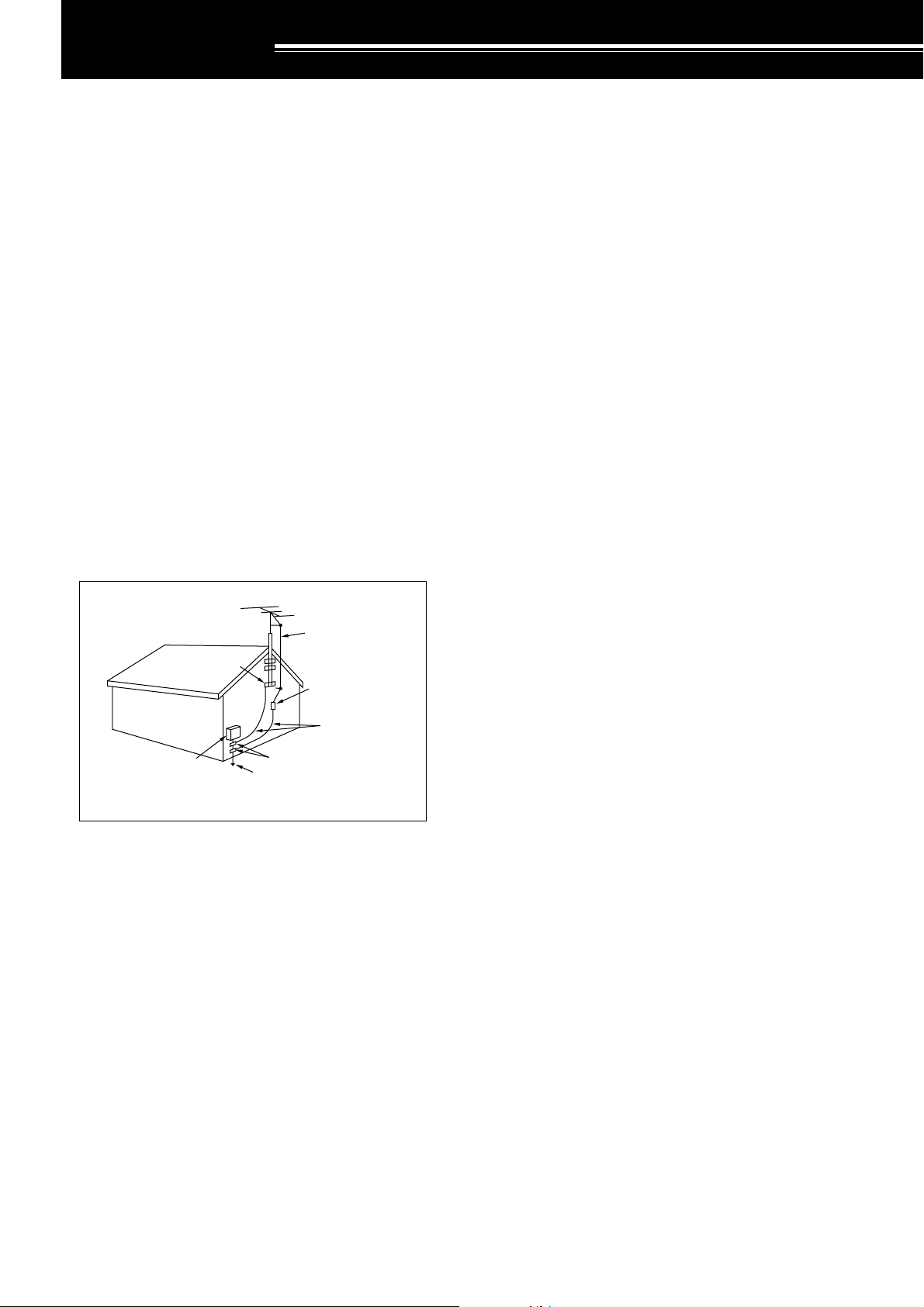
• Adequately ground all outdoor antennas for this
transceiver using approved methods. Grounding
helps protect against voltage surges caused by
lightning. It also reduces the chance of a build-up
of static charge.
EXAMPLE OF ANTENNA GROUNDING
ANTENNA
LEAD IN
GROUND
CLAMP
ELECTRIC SERVICE
EQUIPMENT
POWER SERVICE
GROUNDING ELECTRODE
SYSTEM
WIRE
ANTENNA
DISCHARGE UNIT
GROUNDING
CONDUCTORS
GROUND CLAMPS
•Minimum recommended distance for an outdoor
antenna from power lines is one and one-half
times the vertical height of the associated antenna
support structure. This distance allows adequate
clearance from the power lines if the support
structure fails for any reason.
• Locate the transceiver so as not to interfere with
its ventilation. Do not place books or other
equipment on the transceiver that may impede the
free movement of air. Allow a minimum of
10 cm (4 inches) between the rear of the
transceiver and the wall or operating desk shelf.
• Do not use the transceiver near water or sources
of moisture. For example, avoid use near a
bathtub, sink, swimming pool, or in a damp
basement or attic.
• The presence of an unusual odor or smoke is
often a sign of trouble. Immediately turn the
power OFF and remove the power cable. Contact
a KENWOOD service station or your dealer for
advice.
• Locate the transceiver away from heat sources
such as a radiator, stove, amplifier or other
devices that produce substantial amounts of heat.
• Do not use volatile solvents such as alcohol, paint
thinner, gasoline or benzene to clean the cabinet
of the transceiver. Use a clean cloth with warm
water or a mild detergent.
• Disconnect the input power cable from the power
source when the transceiver is not used for long
periods of time.
• Remove the transceiver’s enclosure only to do
accessory installations described in this manual or
accessory manuals. Follow provided instructions
carefully, to avoid electrical shocks. If unfamiliar
with this type of work, seek assistance from an
experienced individual, or have a professional
technician do the task.
• Enlist the services of qualified personnel in the
following cases:
a) The power supply or plug is damaged.
b) Objects have fallen or liquid has spilled into the
transceiver.
c) The transceiver has been exposed to rain.
d) The transceiver is operating abnormally or
performance has seriously degraded.
e) The transceiver has been dropped or the
enclosure damaged.
• Do not attempt to perform any kind of
configuration or menu setup configuration while
driving your car.
• Do not wear headphones while driving.
• Install the transceiver in a safe and convenient
position inside of your vehicle so as not to subject
yourself to danger while driving. Consult your car
dealer for the transceiver installation to ensure
safety.
• HF/ 50 MHz mobile antennas are larger and
heavier than VHF/ UHF antennas. Therefore, use
a strong and rigid mount to safety and securely
install the HF/ 50 MHz mobile antenna.
iii
Page 6

CONTENTS
NOTICE TO USER
BEFORE STARTING
THANK YOU ............................................................. i
FEATURES ............................................................... i
SUPPLIED ACCESSORIES ..................................... i
MODELS COVERED BY THIS MANUAL ................. ii
MARKET CODES .................................................... ii
WRITING CONVENTIONS FOLLOWED ................. ii
PRECAUTIONS ....................................................... iii
CONTENTS ............................................................ iv
CHAPTER 1 INSTALLATION
MOBILE INSTALLATION ......................................... 1
INSTALLATION EXAMPLE .................................. 1
REMOTE CONTROL PANEL INSTALLATION ..... 1
DC POWER CABLE CONNECTION.................... 2
ANTENNA CONNECTION ................................... 2
IGNITION NOISE ................................................ 2
FIXED STATION INSTALLATION............................. 3
REMOTE CONTROL PANEL INSTALLATION .... 3
DC POWER SUPPLY CONNECTION ................. 3
ANTENNA CONNECTION ................................... 4
GROUND CONNECTION .................................... 4
LIGHTNING PROTECTION ................................. 4
PORTABLE BRACKET (E-TYPE ONLY) .................. 5
FUSES .................................................................... 5
PANEL AND MICROPHONE
CONNECTION .................................................... 6
PANEL AND MICROPHONE CONNECTION
USING PG-4Z (OPTION) ..................................... 6
ACCESSORY CONNECTIONS
TX/ RX UNIT
Micropohone (MIC) ......................................... 7
External Speaker (EXT.SP) ............................. 7
Keys for CW (PADDLE and KEY) ................... 7
REMOTE CONTROL PANEL
Headphones (PHONES) ................................. 7
CHAPTER 2 YOUR FIRST QSO
RECEPTION............................................................ 8
TRANSMISSION ..................................................... 9
CHAPTER 3 GETTING ACQUAINTED
REMOTE CONTROL PANEL ................................. 10
LCD DISPLAY ....................................................... 13
TX/ RX UNIT .......................................................... 15
REMOTE CONTROL PANEL (REAR) .................... 17
MICROPHONE ...................................................... 17
CHAPTER 4 OPERATING BASICS
SWITCHING POWER ON/OFF ............................. 18
ADJUSTING VOLUME .......................................... 18
AF (AUDIO FREQUENCY) GAIN....................... 18
RF (RADIO FREQUENCY) GAIN ...................... 18
SELECTING VFO A OR VFO B ............................. 18
SELECTING A BAND ............................................ 19
SELECTING A MODE ............................................ 19
ADJUSTING SQUELCH ........................................ 19
SELECTING A FREQUENCY ................................ 19
MULTI-FUNCTION METER ................................... 20
TRANSMITTING .................................................... 20
SELECTING TRANSMISSION POWER ............ 20
MICROPHONE GAIN ........................................ 21
CHAPTER 5 MENU SETUP
WHAT IS A MENU?................................................ 22
MENU A/ MENU B ................................................. 22
MENU ACCESS .................................................... 22
QUICK MENU ........................................................ 22
PROGRAMMING THE QUICK MENU ............... 22
USING THE QUICK MENU ............................... 22
MENU CONFIGURATION ..................................... 23
ALPHABETICAL FUNCTION LIST ......................... 26
CHAPTER 6 BASIC COMMUNICATIONS
SSB TRANSMISSION ........................................... 27
FM TRANSMISSION ............................................. 27
AM TRANSMISSION ............................................. 28
NARROW BANDWIDTH FOR FM ......................... 28
NARROW BANDWIDTH FOR AM ......................... 28
CW TRANSMISSION ............................................ 29
AUTO ZERO-BEAT ........................................... 29
TX SIDETONE/ RX PITCH FREQUENCY ......... 29
CHAPTER 7 ENHANCED COMMUNICATIONS
SPLIT-FREQUENCY OPERATION ........................ 30
TF-SET
(TRANSMISSION FREQUENCY SET) .............. 30
FM REPEATER OPERATION ................................ 31
TRANSMITTING A TONE .................................. 32
Activating the Tone Function ......................... 32
Selecting a Tone Frequency.......................... 32
TONE FREQ. ID SCAN ..................................... 32
FM CTCSS OPERATION ....................................... 33
CTCSS FREQ. ID SCAN ................................... 33
CHAPTER 8 COMMUNICATING AIDS
RECEPTION.......................................................... 34
SELECTING YOUR FREQUENCY .................... 34
Direct Frequency Entry ................................. 34
Using the MHz key ........................................ 34
Quick QSY .................................................... 34
Configuring the Tuning control as
MULTI control (FM) ....................................... 34
Fine Tuning................................................... 35
Tuning control adjustment rate ...................... 35
Equalizing VFO Frequencies (A=B) .............. 35
RIT (RECEIVE INCREMENTAL TUNING) ..... 35
AGC (AUTOMATIC GAIN CONTROL) ............... 35
TRANSMISSION ................................................... 36
VOX (VOICE-OPERATED TRANSMIT) ............. 36
Microphone Input Level ................................. 36
Delay Time ................................................... 36
Anti-VOX Adjustment .................................... 36
VOX Source ................................................. 36
SPEECH PROCESSOR .................................... 37
XIT (TRANSMIT INCREMENTAL TUNING) ....... 37
CUSTOMIZING TRANSMISSION SIGNAL
CHARACTERISTICS ......................................... 38
iv
Page 7

CONTENTS
TX Filter Bandwidth (SSB/ AM) ..................... 38
TX Equalizer (SSB/ FM/ AM)......................... 38
TRANSMIT INHIBIT ........................................... 38
BUSY LOCKOUT .............................................. 38
CHANGING FREQUENCY WHILE
TRANSMITTING ................................................ 38
CW BREAK-IN ....................................................... 39
USING SEMI BREAK-IN OR
FULL BREAK-IN ................................................ 39
ELECTRONIC KEYER .......................................... 39
CHANGING KEYING SPEED ............................ 39
AUTO WEIGHTING ........................................... 39
Reverse Keying Weight Ratio ....................... 39
BUG KEY FUNCTION ....................................... 40
CW MESSAGE MEMORY ................................. 40
Storing CW Messages .................................. 40
Checking CW Messages without
Transmitting .................................................. 40
Transmitting CW Messages .......................... 40
Changing the Inter-message Interval Time .... 41
Changing the Sidetone Volume ..................... 41
Inset Keying .................................................. 41
FREQUENCY CORRECTION FOR CW ............ 41
AUTO CW TX IN SSB MODE ............................ 41
MIC UP/ DWN KEY PADDLE MODE ................. 41
SWAP DOT AND DASH PADDLE POSTION ..... 41
CHAPTER 9 SPECIALIZED COMMUNICATIONS
RADIO TELETYPE (RTTY) .................................... 42
AMTOR/ PacTOR/ CLOVER/ G-TOR/ PSK31........ 43
PACKET RADIO .................................................... 43
SLOW SCAN TV/ FACSIMILE ............................... 44
CHAPTER 10 REJECTING INTERFERENCE
IF FILTER .............................................................. 45
CHANGING THE IF FILTER BANDWIDTH ........ 45
SSB/ AM ....................................................... 45
CW/ FSK ...................................................... 45
FM ................................................................ 45
IF SHIFT (SSB/ CW/ FSK) ................................. 45
DSP FILTERS
CHANGING THE DSP FILTER BANDWIDTH .... 46
SSB/ FM/ AM ................................................ 46
CW/ FSK ...................................................... 46
BEAT CANCEL (SSB/ FM/ AM) .......................... 47
NOISE REDUCTION (ALL MODES) .................. 47
Setting the NR1 Level Adjustment ................. 47
Settign the NR2 Time Constant ..................... 47
NOISE BLANKER .................................................. 47
DIGITAL NOISE LIMITER (DNL) ............................ 47
DSP FILTER FOR DATA COMMUNICATION
(SSB/ FM) .............................................................. 48
DSP RX MONITOR................................................ 48
PRE-AMPLIFIER ................................................... 49
ATTENUATOR ....................................................... 49
CW REVERSE ...................................................... 49
CHAPTER 11 MEMORY FEATURES
MEMORY CHANNELS .......................................... 50
STORING DATA IN MEMORY ........................... 50
Simplex Channels ......................................... 50
Split-Frequency Channels ............................. 51
MEMORY RECALL AND SCROLL .................... 51
Memory Recall .............................................. 51
Memory Scroll ............................................... 52
Temporary Frequency Changes .................... 52
MEMORY TRANSFER ...................................... 52
Memory ➡ VFO Transfer .............................. 52
Channel ➡ Channel Transfer ........................ 52
STORING FREQUENCY RANGES ................... 53
Confirming Start/End Frequencies ................ 53
Programmable VFO ...................................... 54
MEMORY CHANNEL LOCKOUT ....................... 54
ERASING MEMORY CHANNELS ..................... 54
MEMORY CHANNEL NAME ............................. 54
QUICK MEMORY .................................................. 55
STORING INTO QUICK MEMORY .................... 55
RECALLING QUICK MEMORY CHANNELS ..... 55
TEMPORARY FREQUENCY CHANGES .......... 55
QUICK MEMORY ➡ VFO TRANSFER .............. 55
CHAPTER 12 SCAN
NORMAL SCAN .................................................... 56
VFO SCAN ........................................................ 56
PROGRAM SCAN ............................................. 56
PROGRAM SCAN PARTIALLY SLOWED.......... 57
SCAN HOLD ..................................................... 57
MEMORY SCAN.................................................... 58
SCAN RESUME METHOD ................................ 58
ALL-CHANNEL SCAN ....................................... 58
GROUP SCAN .................................................. 59
Memory Group ............................................. 59
Scan Group Select ........................................ 59
Performing Group Scan ................................ 59
CHAPTER 13 OPERATOR CONVENIENCES
ANTENNAS ........................................................... 60
APO (Auto Power OFF) ......................................... 60
AUTOMATIC ANTENNA TUNER ........................... 60
PRESETTING ................................................... 61
EXTERNAL ANTENNA TUNER TYPE ............... 61
ATTENUATOR ....................................................... 61
AUTO MODE ......................................................... 61
BEEP FUNCTION .................................................. 62
DISPLAY ............................................................... 63
BRIGHTNESS ................................................... 63
KEY ILLUMINATION .......................................... 63
LINEAR AMPLIFIER CONTROL ............................ 63
LOCK FUNCTIONS ............................................... 63
FREQUENCY LOCK FUNCTION ...................... 63
TUNING CONTROL LOCK FUNCTION ............. 63
MICROPHONE PF KEYS ...................................... 64
PF KEY .................................................................. 64
RX DSP EQUALIZER ............................................ 64
EQUALIZING RECEIVING AUDIO..................... 64
RX MONITOR ........................................................ 64
v
Page 8

CONTENTS
TIME-OUT TIMER ................................................. 65
TRANSVERTER .................................................... 65
FREQUENCY DISPLAY .................................... 65
TRANSMISSION OUTPUT POWER .................. 65
TX MONITOR ........................................................ 65
TX POWER ........................................................... 65
TX TUNE ............................................................... 66
QUICK DATA TRANSFER ..................................... 67
SETTING UP ..................................................... 67
Equipment Needed ....................................... 67
Connections ................................................. 67
USING QUICK TRANSFER ............................... 67
Transferring Data .......................................... 67
Receiving Data ............................................. 67
COMPUTER CONTROL ........................................ 68
SETTING UP ..................................................... 68
Equipment Needed ....................................... 68
Connections ................................................. 68
COMMUNICATION PARAMETERS ................... 68
CONTROLLING THE TS-480 FROM PC ........... 68
REMOTE CONTROLLING THE TS-480
ON THE NETWORK .......................................... 68
VGS-1 VOICE GUIDE AND STORAGE UNIT
(OPTIONAL) .......................................................... 68
RECORDING MESSAGES ................................ 68
MESSAGE PLAYBACK ..................................... 69
Checking Messages ..................................... 69
Sending Messages ....................................... 69
Erasing a Recorded Message ....................... 69
Changing Inter-message Interval Time .......... 69
Changing Playback Volume .......................... 69
CONSTANT RECORDING ................................ 69
VOICE GUIDE ................................................... 70
Voice Guide Announcement Volume ............. 71
Voice Guide Announcement Speed............... 71
DX PACKETCLUSTER TUNE ............................... 72
SKY COMMAND II (K-TYPE ONLY) ...................... 73
SKY COMMAND II DIAGRAM ........................... 73
PREPARATION ................................................. 73
CONTROL OPERATION ................................... 73
USING THE TH-D7A AS A COMMANDER ......... 74
CONTROL OPERATION ................................... 74
YF-107C/ CN/ SN IF FILTERS AND
SO-3 TCXO ........................................................... 81
REFERENCE FREQUENCY CALIBRATION ..... 82
CHAPTER 16 TROUBLESHOOTING
GENERAL INFORMATION .................................... 83
SERVICE ........................................................... 83
SERVICE NOTE ................................................ 83
CLEANING ........................................................ 83
BACKUP BATTERY ............................................... 83
TROUBLESHOOTING ........................................... 84
MICROPROCESSOR RESET ............................... 88
INITIAL SETTINGS ............................................ 88
PARTIAL RESET ............................................... 88
FULL RESET ..................................................... 88
DEMONSTRATION MODE .................................... 88
OPERATION NOTICES ......................................... 89
DC POWER SUPPLY ........................................ 89
FAN NOISES ..................................................... 89
INTERNAL BEATS ............................................ 89
AGC .................................................................. 89
60 m BAND OPERATION
(K-TYPE/ USA ONLY) ........................................ 89
CHAPTER 17 OPTIONAL ACCESSORIES
OPTIONAL ACCESSORIES .................................. 90
CHAPTER 18 SPECIFICATIONS
SPECIFICATIONS ................................................. 91
CHAPTER 19 INDEX
INDEX ................................................................... 93
CHAPTER 14 CONNECTING PERIPHERAL EQUIPMENT
COMPUTER .......................................................... 76
COMPATIBLE TRANSCEIVER .............................. 76
RTTY OPERATION................................................ 77
HF/ 50 MHz LINEAR AMPLIFIER .......................... 77
ANTENNA TUNER ................................................ 78
MCP AND TNC ...................................................... 78
DX PACKETCLUSTER TUNE ............................... 79
CROSSBAND REPEATER .................................... 79
SKY COMMAND II (K-TYPE ONLY) ...................... 80
CHAPTER 15 INSTALLING OPTIONS
REMOVING THE TOP COVER ............................. 81
VGS-1 VOICE GUIDE AND STORAGE UNIT ........ 81
vi
Page 9
INSTALLATION
MOBILE INSTALLATION
When you use this transceiver for mobile operation, do not attempt to perform any kind of configuration or menu
setup configuration while driving your car; it is simply too dangeous. Stop the car and then perform transceiver
configuration. In addition, do not wear headphones while driving.
You should install the transceiver in a safe and convenient position inside your vehicle so as not to subject
yourself to danger while driving. For example, install the transceiver under the dash in front of the passenger seat
so that knees or legs will not strike the transceiver if you brake suddenly. Additionally, do not install the
transceiver and its accessories on to the air bag lids. We recommend you consult your car dealer for the
transceiver installation to ensure safety.
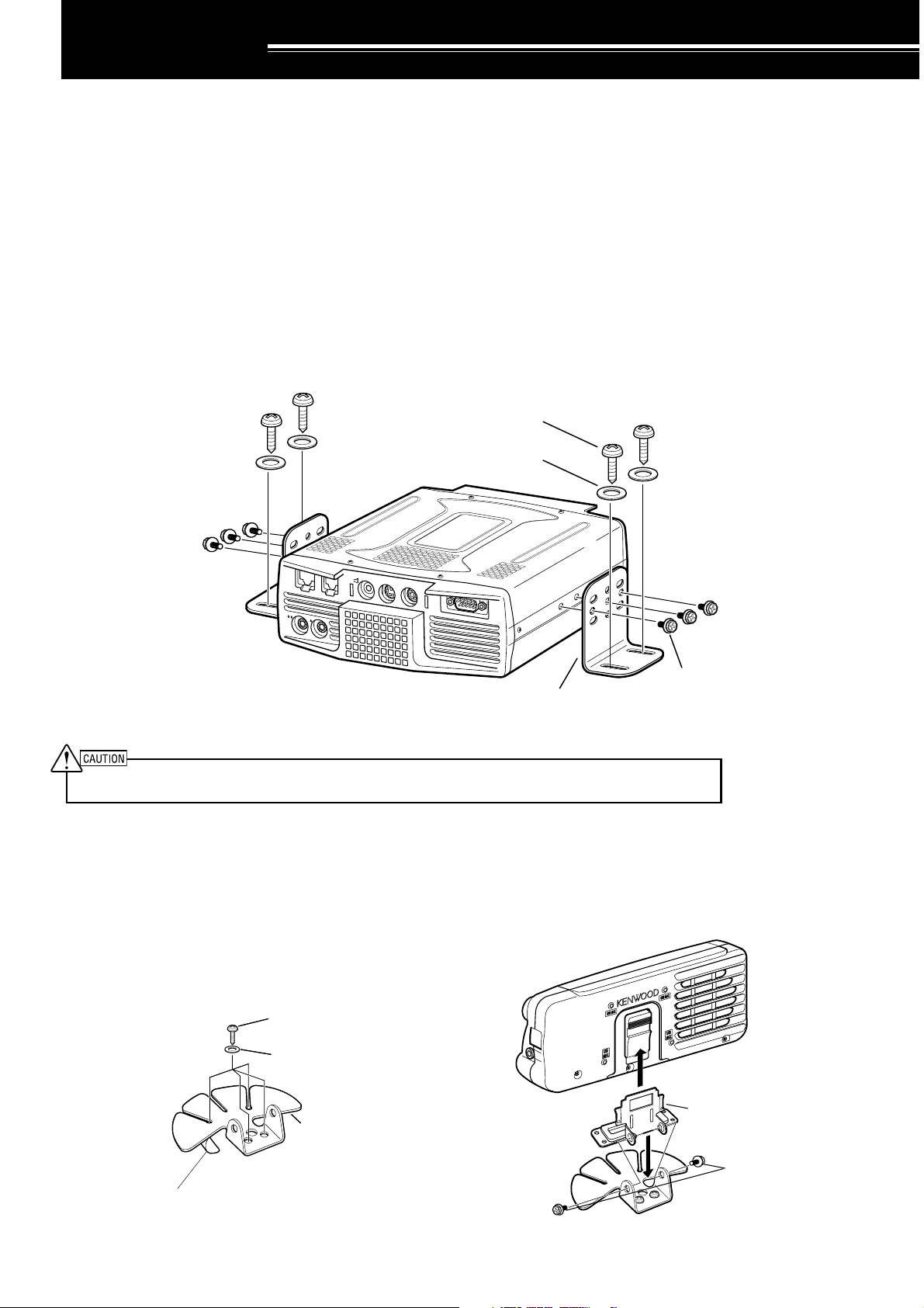
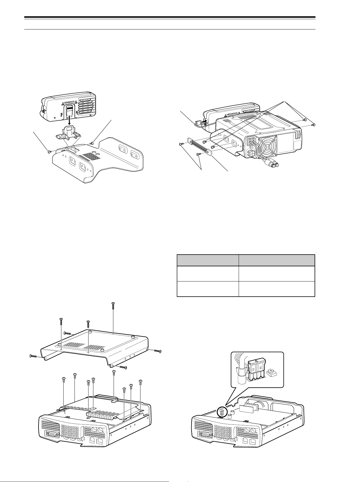
INSTALLATION EXAMPLE
1 Attach the 2 L-brackets using the 6 supplied SEMS screws (M4 x 10 mm) as shown below.
2 Position the transceiver in the mounting bracket and tighten the 4 supplied tapping screws (5 mm x 16 mm) to
fix the transceiver in place.
Tapping screw
(5 mm x 16 mm)
Flat washer
(5 mm)
KEY
EXT.SP DATA REMOTE
PANEL
COM
SEMS screw
L-bracket
(M4 x 10 mm)
MIC
PADDLE
Do not install the TX/ RX unit in non-ventilated areas. Air must flow through the TX/ RX unit to keep the unit cooled.
REMOTE CONTROL PANEL INSTALLATION
1 Peel off the adhesive tape cover from the bottom of the fan-shaped base.
2 Afix the holder to the vehicle with 4 tapping screws.
3 Attach the Remote Control panel holder to the base with 2 supplied SEMS screws.
Tapping screw
4 mm x 12 mm
Adhesive tape cover
Flat washer (4 mm)
Remote Control
panel holder
SEMS screws
(M4 x 10 mm)
1
Page 10
1 INSTALLATION
DC
13.8V
1
DC 2 13.8V
AT
GND
2
DC
13.8V
1
DC 2 13.8V
AT
GND
2
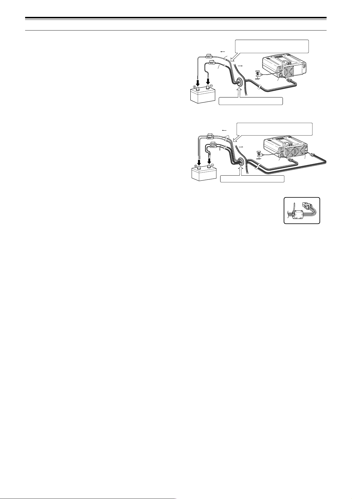
DC POWER CABLE CONNECTION
Connect the DC power cable directly to the vehicle’s
battery terminals using the shortest route. Do not use
the cigarette lighter socket! The current rating of the
cigarette lighter socket is too small to operate the
transceiver. Ensure to use a 12 V vehicle battery
which has sufficient current capacity. If the current is
insufficient, the display may darken during
transmission or the trasceiver may work
intermittiently. If you use the transceiver for a long
period when the vehicle battery has not been fully
charged or when the engine has been stopped, the
battery may become discharged in a short time and
will not have sufficient reserves to start the engine.
Avoid using the transceiver under these conditions.
Keep in mind that the TS-480SAT transceiver draws a
peak current of approximately 20.5 A and the
TS-480HX transceiver draws a peak current of
approximately 41A (20.5A + 20.5A) during
transmission.
• Attach the line filter(s) to the DC cable(s) as
shown after the installation (E-type only).
Note:
◆
Do not use two separate batteries to connect each DC cables
from the transceiver (TS-480HX). The DC voltage difference
between DC IN 1 and DC IN 2 connectors at the transceiver must
be within DC 1.0 V to operate the transceiver.
◆
Two supplied DC cables (or two optional PG-20 DC cables) must
be used. Using different length and/ or different gauged cable
could result in a voltage difference between DC IN 1 and DC IN 2
connectors at the transceiver (TS-480HX).
Engine compartment
Black (—)
12 V battery
Engine compartment
Black (–)
12 V battery
Place the DC cable the wall of the engine compartment
securely. Avoid applying excessive heat, vapor and water to
the cable.
Red (+)
Passenger
Compartment
Use a rubber or plastic grommet so that the cable
does not directly touch the vehicle chassis.
Place the DC cable the wall of the engine compartment
securely. Avoid applying excessive heat, vapor and water to
the cable.
Red (+)
Passenger
Compartment
Use a rubber or plastic grommet so that the cable
does not directly touch the vehicle chassis.
Body
Body
DC
13.8V
DC IN
DC IN 1
1
2
D
GND
GN
TS-480SAT
1
2
ND
GNDG
DC
13.8V
TS-480HX
E-type only
DC IN 2
ANTENNA CONNECTION
In general, HF/ 50 MHz mobile antennas are larger and heavier than VHF/ UHF antennas. Therefore, use a
strong and rigid mount to safety and securely install the HF/ 50 MHz mobile antenna.
A bumper mount is recommended for stable mounting. However, most recent models of vehicles have plastic
bumpers. For such vehicles, ground the antenna mount to the body chassis with a large wire. Antenna
installation is critical for successful mobile operation. For further information, refer to The Radio Amateur’s
Handbook, Radio Handbook, or other published texts.
GROUND CONNECTION
The ground, which is the other half of the antenna system, is very important when using a mobile whip type
antenna. Connect the feed line ground for the antenna securely to the vehicle’s chassis, and be certain to bond
(electrically connect) the vehicle’s body to chassis. The sheet metal will provide the primary ground plane, so be
sure to establish a good RF connection from the feed line to both the chassis and the body. For comprehensive
information on mobile antennas installations and optimization, refer to the ARRL Handbook or similar publications.
IGNITION NOISE
This transceiver has been equipped with a Noise Blanker and Digital Noise Limiter to filter ignition noises out.
However, some cars may generate excessive ignition noise. If there is excessive noise, use suppressor spark
plugs (with resisters), and/ or DC line filters to reduce the electric noises. The ARRL Handbook, or similar
refereneces, has a wealth of information regarding this topic.
Note:
◆
After installation and wiring are completed, confirm that all work has been done correctly, then connect the DC power cable plug(s) to the
transceiver.
◆
If the fuse blows, disconnect the DC power cable plug(s) from the transceiver immediately, then check all the DC power cables to find the
reasons of the short circuit. The DC cable may be damaged, short circuited, pinched, or squashed. After resolving the problem, replace the
fuse with one of the same type and rating.
◆
Do not remove the fuse holder for any reason.
2
Page 11
1 INSTALLATION
DC
13.8V
1
DC 2 13.8V
AT
GND
2
DC
13.8V13.8V
1
DC 2 13.8V
AT
GNDGNDGND
22
1
Black (–)
Red (+)
Fuse (25 A)
DC IN 1
DC 13.8 V
DC IN 2
DC 13.8 V
Red (+)
Fuse (25 A)
DC Power supply
(20.5 A or more)
DC Power supply
(20.5 A or more)
FIXED STATION INSTALLATION
When you use the transceiver at a fixed location, the transceiver requires 13.8 V DC power supply
(The TS-480HX requires 2 DC power supplies).
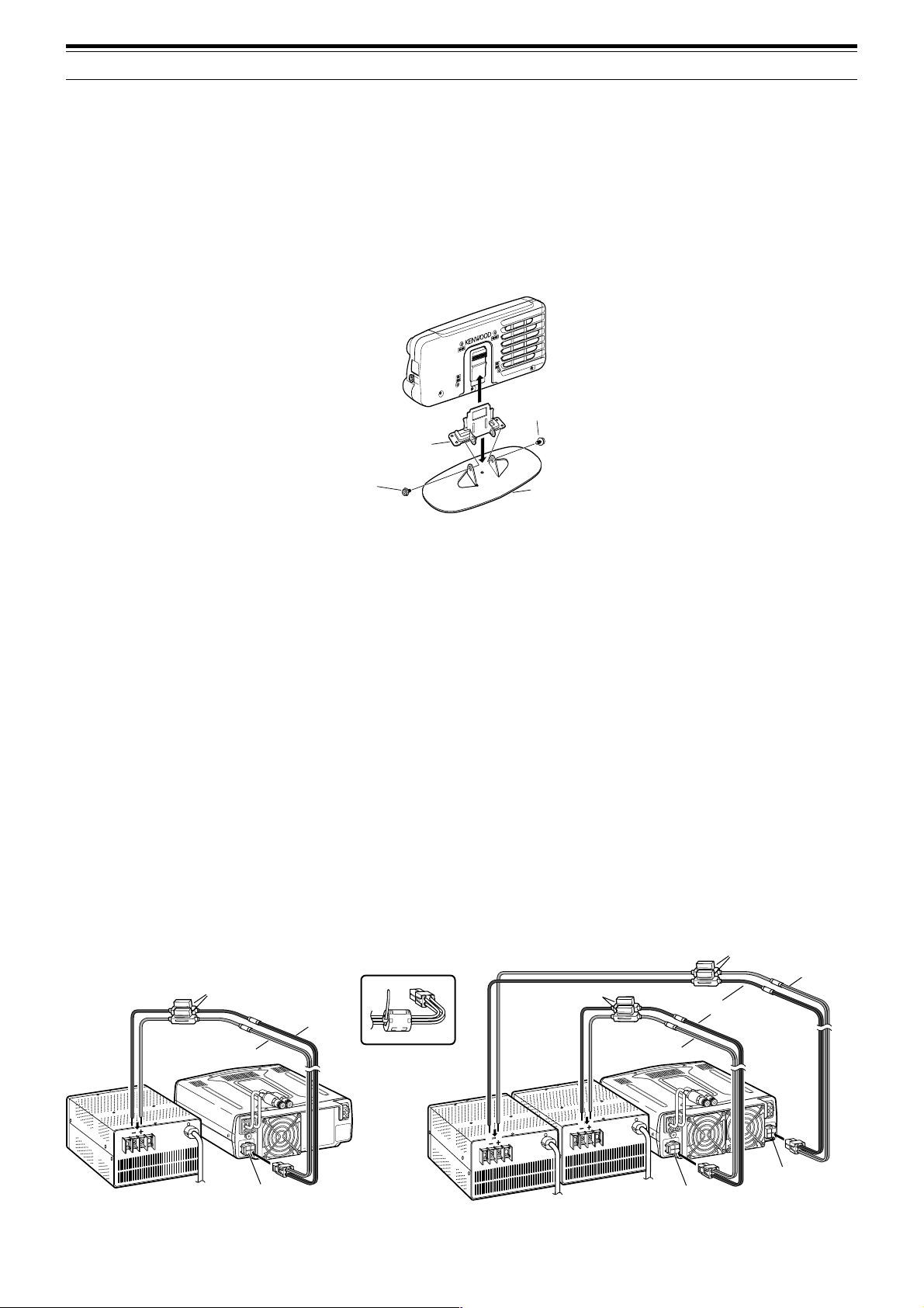
REMOTE CONTROL PANEL INSTALLATION
1 Attach the oval-shaped base to the front panel mounting bracket using two SEMS screws (M4 x 10 mm) as
shown below.
2 Slide the Remote Control panel along the mounting bracket rails until secure.
SEMS screw
(M4 x 10 mm)
Panel holder
SEMS screw
(M4 x 10 mm)
Base stand
DC POWER SUPPLY CONNECTION
In order to use this transceiver, you need a separate 13.8 V DC power supply (two 13.8 V/ 20.5 A or single
13.8 V/ 41.0 A DC power supply(s) is required to transmit for the TS-480HX) that must be purchased separately.
Do not directly connect the transceiver to an AC outlet. Use the supplied DC power cables to connect the
transceiver to a regulated power supply. Do not substitute a cable with smaller gauge wires. The current capacity
of each power supply must be 20.5 A peak or more.
1 Connect the DC power cable(s) to the regulated DC power supply (two 13.8 V/ 20.5 A or single 13.8 V/ 41.0 A
DC power supply(s) must be used for the TS-480HX); the red lead to the positive terminal and the black lead to
the negative terminal.
• When using a single 13.8 V/ 41 A DC power supply, connect 2 DC cables to the positive and negative
terminals, as shown on page 2.
2 Connect the DC power cable to the transceiver’s DC power connector.
• Press the connectors firmly until the locking tab clicks.
• Attach the line filter(s) to the DC cable(s) as shown below (E-type only).
Note:
◆
Before connecting the DC power supply to the transceiver, be sure to switch OFF the DC power supply and the transceiver.
◆
Do not plug the DC power supply into an AC outlet until you make all connections.
◆
When two power supplies are used for the TS-480HX, the DC voltage difference at the transceiver DC IN connectors must be within 1.0 V DC.
◆
Do not use different types (length and gauge) of DC cables to avoid voltage differences (TS-480HX).
DC Power supply
(20.5 A or more)
Fuse (25 A)
Red (+)
2
GNDGND
DC
13.8V
DC IN 1
DC 13.8 V
E-type only
Black (—)
1
TS-480SAT TS-480HX
3
Page 12

1 INSTALLATION
ANTENNA CONNECTION
An antenna system consists of an antenna, feed line, and ground. The transceiver can give excellent results if the
antenna system and its installation are given careful attention. Use a properly adjusted 50 Ω antenna of good
quality, a high-quality 50 Ω coaxial cable, and first-quality connectors. All connections must be clean and tight.
After making the connections, match the impedance of the coaxial cable and antenna so that the SWR is 1.5:1 or
less. High SWR will cause the transmit output to drop and may lead to radio frequency interference to consumer
products such as stereo receivers and televisions. You may even interfere with your own transceiver. Reports
that your signal is distorted could indicate that your antenna system is not efficiently radiating the transceiver’s
power.
Connect your primary HF/ 50 MHz antenna feed line to ANT 1 on the rear of the transceiver. If you are using two
HF/ 50 MHz antennas, connect the secondary antenna to ANT 2. Refer to page 16 for the location of the antenna
connectors.
Note:
◆
Transmitting without connecting an antenna or other matched load may damage the transceiver. Always connect the antenna to the
transceiver before transmitting.
◆
All fixed stations should be equipped with a lightning arrester to reduce the risk of fire, electric shock, and transceiver damage.
◆
The transceiver’s protection circuit will activate when the SWR is greater than 2.5:1; however, do not rely on protection to compensate for a
poorly functioning antenna system.
GROUND CONNECTION
At the minimum, a good DC ground is required to prevent such dangers as electric shock. For superior
communications results, a good RF ground is required against which the antenna system can operate. Both of
these conditions can be met by providing a good earth ground for your station. Bury one or more ground rods or
a large copper plate under the ground, then connect this to the transceiver GND terminal. Use heavy gauge wire
or a copper strap, cut as short as possible, for this connection. Do not use a gas pipe, an electrical conduit, or a
plastic water pipe as a ground.
LIGHTNING PROTECTION
Even in areas where lightning storms are less common, there are usually a limited number of storms each year.
Consider carefully how to protect your equipment and home from lightning. The installation of a lightning arrestor
is a start, but there is more that you can do. For example, terminate your antenna system transmission lines at an
entry panel that you install outside your home. Ground this entry panel to a good outside ground, then connect
the appropriate feed lines between the entry panel and your transceiver. When a lightning storm occurs,
disconnecting the feed lines from your transceiver will ensure additional protection.
4
Page 13
1 INSTALLATION
noitacoLesuF gnitaRtnerruCesuF
TAS/XH084-ST
)tinuXR/XT(
A4
)renutannetnalanretxenaroF(
rewopCDdeilppuS
elbac
A52
DC
13.8V
1
DC 2 13.8V
AT
GNDGNDGND
22
1
PORTABLE BRACKET (E-TYPE ONLY)
Using the supplied Portable Bracket, you can carry the Remote Control panel and TX/ RX unit together.
Two TX/ RX unit positions are available. If you do not use the EXT.SP, REMOTE and DATA connectors, place the
TX/ RX unit in front position. If you use the EXT.SP, REMOTE or DATA connector, place the TX/ RX unit to the
back position. You can also attach the handle as shown if necessary. Use the supplied short cable (RJ11/ 20 cm)
to connect the Remote Control panel and the TX/ RX unit.
Binding head screw
(M4 x 8 mm)
RJ11/ 20 cm
SEMS screw
(M4 x 10 mm)
SEMS screw
(M4 x 10 mm)
Flat-head screw
(M4 x 12 mm)
Carrying handle
FUSES
The following fuses are used in the TS-480HX/ SAT transceiver. If a fuse blows, determine the cause then correct
the problem. Only after the problem has been resolved, replace the blown fuse with a new one with the specified
ratings. If newly installed fuses continue to blow, disconnect the power plug and contact a KENWOOD service
center or your dealer for assistance.
1 Remove 7 screws at the bottom of the TX/ RX unit.
2 Remove 8 screws inside of the TX/ RX unit.
3 Lift the shield cover.
4 Replace 4 A fuse.
COM
KEY
PADDLE
PANEL
REMOTE
DATA
EXT.SP
MIC
COM
REMOTE
DATA
KEY
DDLE
PA
PANEL
EXT.SP
MIC
5
Page 14
1 INSTALLATION
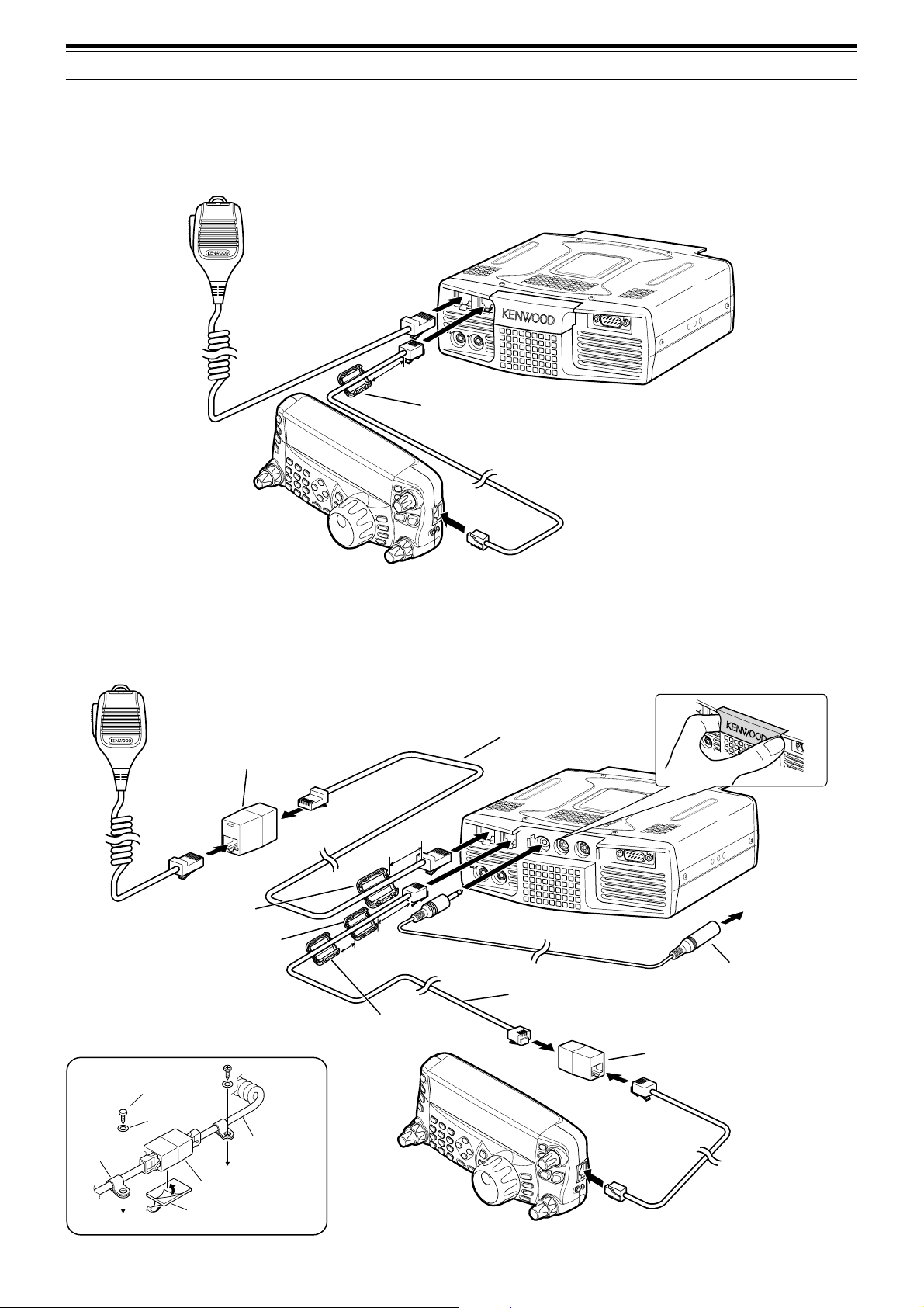
PANEL AND MICROPHONE CONNECTION
Plug the microphone plug to the MIC jack (8-wire/ RJ45), then connect the Remote Control panel to the TX/ RX
unit with the supplied cable (2 m/ 6-wire/ RJ11).
Microphone
EXT.SP DATA REMOTE
PANEL
COM
KEY
To MIC
3cm
MIC
PADDLE
To PANEL
Line filter
PANEL AND MICROPHONE CONNECTION USING PG-4Z (OPTION)
Use the cables and connectors to connect the Remote Control panel and TX/ RX unit with the PG-4Z cable kit as
shown below.
EXT.SP DATA
Extension adaptor (RJ45)
from the PG-4Z cable kit
Line filter (large) from
the PG-4Z cable kit
Line filter (small) from
the TS-480
To MIC
3 cm
3 cm
1 cm
Line filter (small) from
the PG-4Z cable kit
MIC
PADDLE
To EXT.SP
Extension cable (RJ45)
from the PG-4Z cable kit
EXT.SP
DATA REMOTE
PANEL
KEY
Extension cable (RJ11)
from the PG-4Z cable kit
PANEL
COM
External speaker extension
cable from the PG-4Z cable
kit (when the external speaker
is used)
Extension adaptor (RJ11)
from the PG-4Z cable kit
REMOTE
To external speaker
Tapping screw
(4 mm x 14 mm)
Flat washer
Cable
holder
Microphone cable
RJ45 (8-wire)
adaptor
Double-sided
adhesive tape
6
Page 15
ACCESSORY CONNECTIONS
TX/ RX UNIT
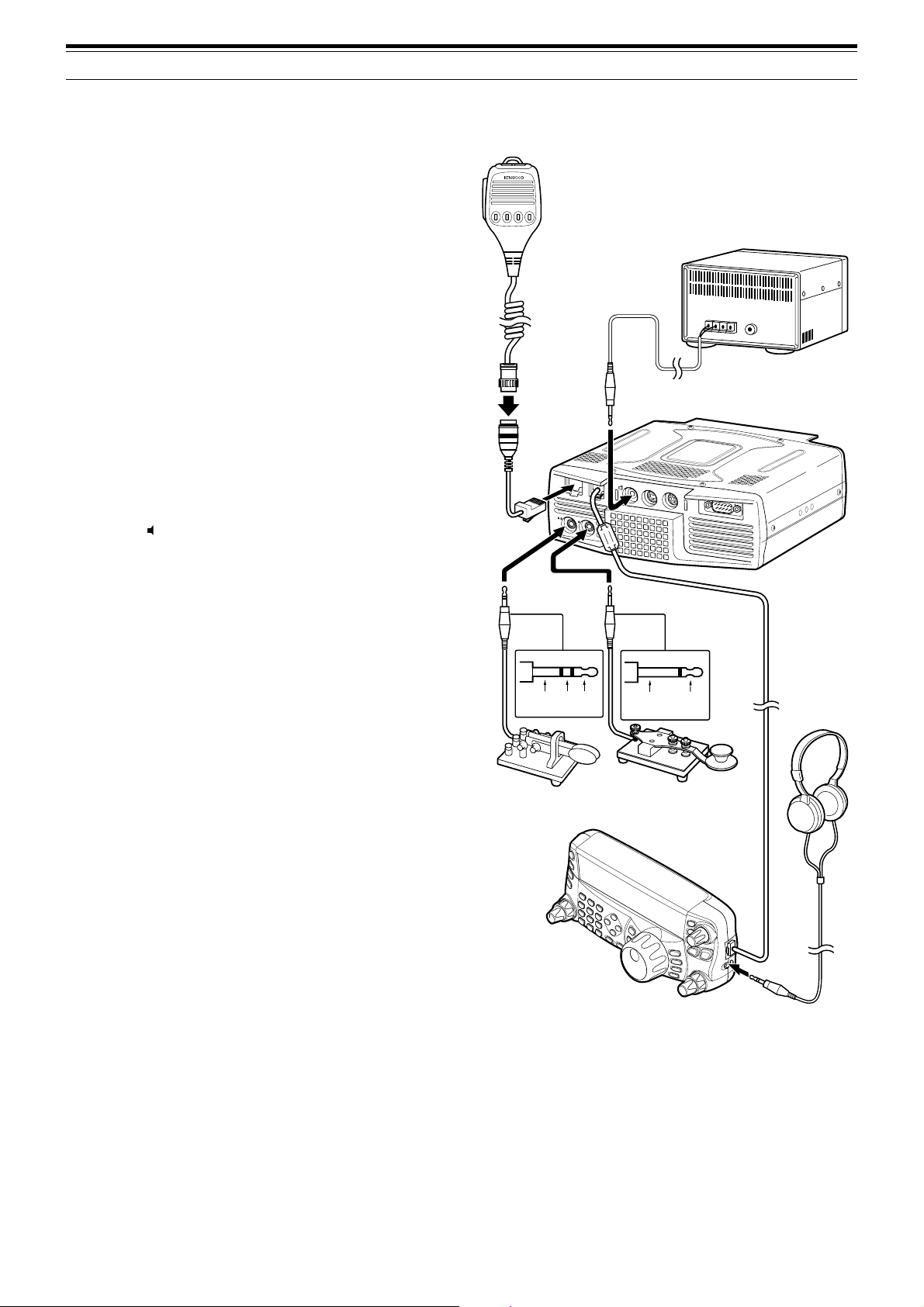
■ Microphone (MIC)
Connect a microphone having an impedance
between 250 and 600 Ω. As for the supplied
microphone, fully insert the modular connector into
the MIC jack until the locking tab clicks. You can
still utilize 8-pin metal type plug microphones,
such as MC-43S, MC-47, and MC-60A with the
optional MJ-88 adaptor (optional) if necessary.
However, do not use the MC-44, MC-44DM,
MC-45, MC-45E, MC-45DM, MC-45DME, or
MC-53DM condensor-type microphones.
■ External Speaker (EXT.SP)
On the front panel of the TX/ RX unit, there is an
external speaker jack. If an external speaker is
connected to EXT.SP jack, the built-in speaker on
the back of the Remote Control panel will mute.
Use only external speakers with an impedance of
4 to 8 Ω (8 Ω nominal). The jacks accept only
3.5 mm (1/8") diameter, 2-conductor (mono) plugs.
• The “ ” projection indicates the external
speaker jack.
1234
Microphone
w/ 8-pin metal plug
(Opt.)
MJ-88
(Opt.)
MIC
PADDLE
1 INSTALLATION
External speaker (Opt.)
EXT.SP
DATA
PANEL
KEY
REMOTE
COM
Note:
Do not connect headphones to this jack. The high audio
output of this jack could damage your hearing.
■ Keys for CW (PADDLE and KEY)
For CW operation using the internal electronic
keyer, connect a keyer paddle to the PADDLE
jack. For CW operation without using the internal
electronic keyer, connect a straight key,
semi-automatic key (bug), electronic keyer, or the
CW keying output from a Multi-mode
Communications Processor (MCP) to the KEY
jack. The PADDLE and KEY jacks mate with a
3.5 mm (1/8") 3-conductor plug and a 3.5 mm
(1/8") 2-conductor plug respectively. External
electronic keyers or MCPs must have a positive
keying output to be compatible with this
transceiver. Use a shielded cable between the
key and the transceiver.
• The “•” projection indicates the key jack and
the “••” projection indicates the paddle jack.
Note:
Due to the functionality of the internal electronic keyer, you
may find it unnecessary to connect both a paddle and another
type of keyer unless you want to use a PC-based keyer for CW.
Refer to the “ELECTRONIC KEYER” section {page 39} to
become familiar with the internal keyer.
GND dash dot
Paddle
+GND
Straight key
Bug key
Electric keyer
MCP CW output
Headphones
REMOTE CONTROL PANEL
■ Headphones (PHONES)
Connect monaural or stereo headphones having a
4 to 32 Ω impedance. This jack accepts a
3.5 mm (1/8") diameter, 2-conductor (mono) or
3-conductor (stereo) plug. After connecting the
headphones, you will hear no sound from the
internal (or optional external) speaker.
7
Page 16
YOUR FIRST QSO
w
RECEPTION
PF
ANT 1/2
ATT/PRE
r
qu
AT
AF SQL
1 REC 2 REC
CH1 CH2 CH3
4
TX MONI
PWR
7
NB/T
CLR
MTR
5 RF.G
MIC KEY
8
VOX
0 OFF
AGC
3 REC
6
9
PROC
DELAY
ENT
DNL
NR FIL
BC
STEP SG.SEL
FINE SCAN
qr
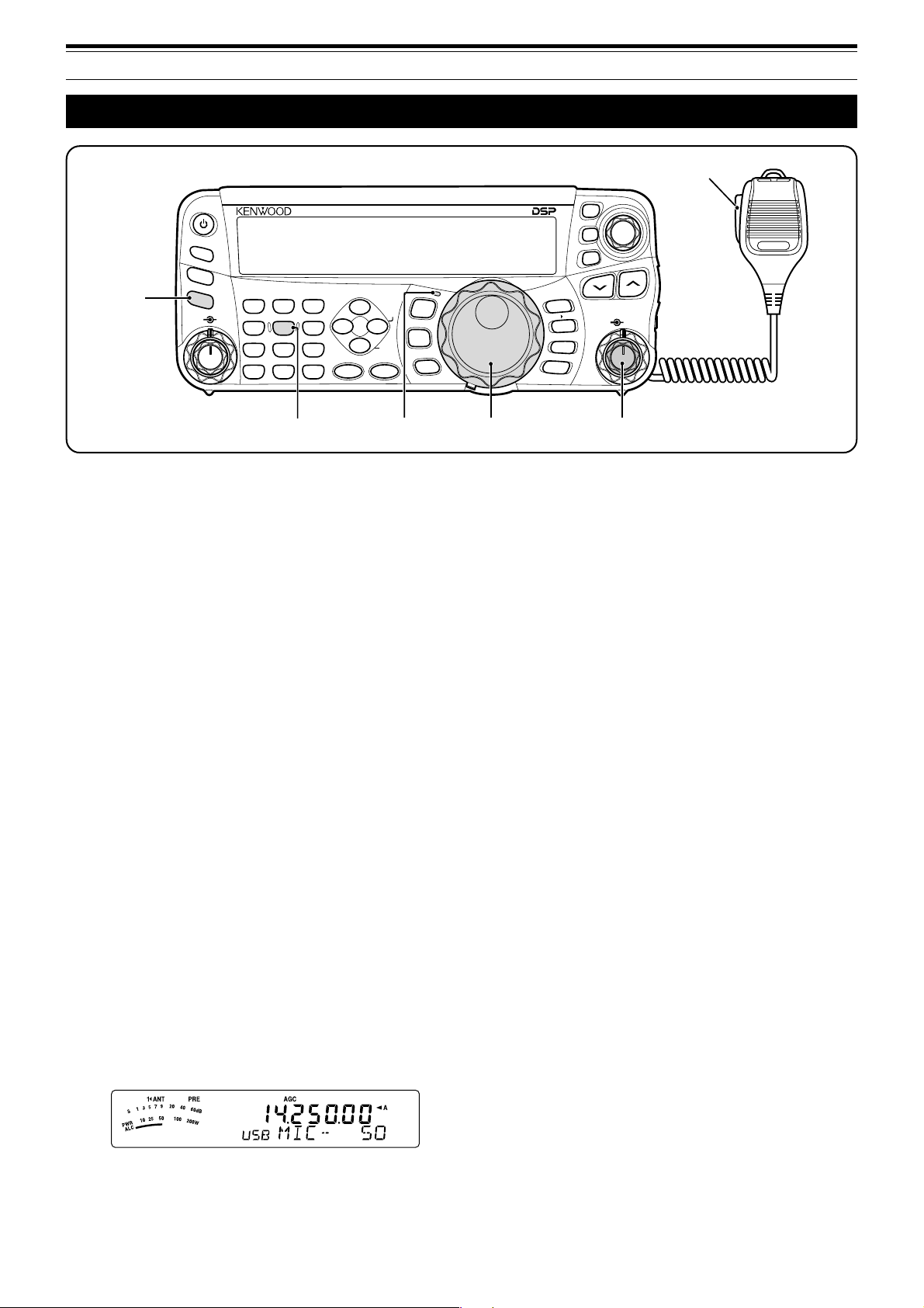
Are you ready to give your TS-480HX/ SAT a quick
try? Reading these two pages should get your voice
on the air in your first QSO on the HF/ 50 MHz band
shortly. The instructions below are intended only for
a quick guide. If you encounter problems or there is
something you don’t understand, read the detailed
explanations given later in this manual.
Note:
This section explains only keys and controls required to
briefly try the transceiver.
q Set the following as specified:
• AF control: Fully counterclockwise
• SQL control: Fully counterclockwise
Then, switch ON the DC power supply if you are
using the DC power supply. If you are operating the
transceiver with the car batteries, ensure that the DC
power source(s) are available at the DC connector(s).
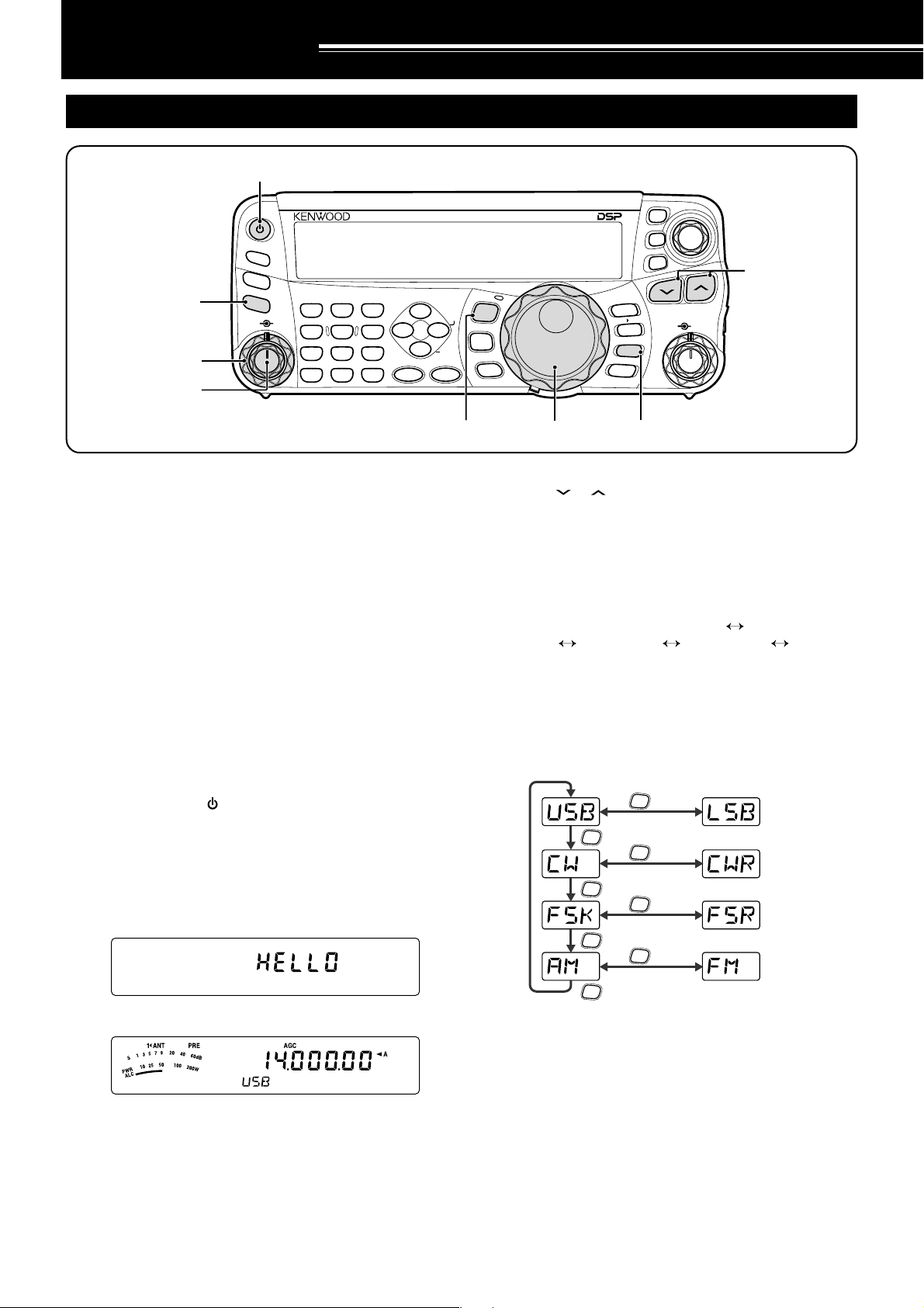
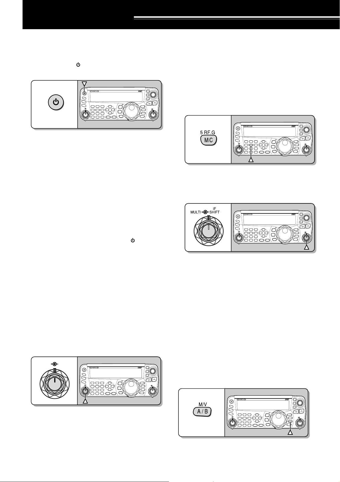
w Press and hold [ ] (POWER) briefly to turn ON
the transceiver.
• Do not press the switch for more than
approximately 2 seconds; the transceiver will
be switched OFF.
• Upon power up, “HELLO” appears, followed by
the selected frequency and other indicators.
M.IN
QMI
A=B
M VFO
QMR
M/V
A / B
SPLIT
CL
XIT
RIT
TF-SET
MULTIIFSHIFT
e
HF/50MHz ALL MODE TRANSCEIVER TS-480
MODE
NAR
F.LOCK
MENU
CW.T
MHz
y
i
t Press [ ]/ [ ] to select a desired HF/ 50 MHz
Amateur radio band.
y Press [MODE] to select the desired
communication mode.
• There are 4 mode pairs: USB/ LSB, CW/ CWR
(Reversed pitch), FSK/ FSR (Reverse shift)
and AM/ FM. Press [MODE] (1 s) to toggle the
mode within each pair: USB LSB,
CW CWR, FSK FSR, or AM FM.
•To select the alternate mode on each operating
mode, press and hold the key for 1 second.
For example, if USB is selected, press
[MODE] (1 s) to switch to LSB mode. The
following diagram illustrates how to access
each mode.
MODE
(1 s)
MODE
MODE
MODE
MODE
MODE
MODE
(1 s)
(1 s)
(1 s)
t
d
e Confirm that VFO A has been selected for
communications; “tA” should be visible on the
display. If it has not, press [A/B / M/V] to select
VFO A.
r Turn the AF control slowly clockwise until you hear
a suitable level of background noise.
8
MODE
u If you have selected FM, turn the SQL control
clockwise until the background noise is just
eliminated; the green LED (above the [MODE]
key) turns OFF.
• With LSB or USB selected, skip this step.
i Turn the Tuning control to tune in a station.
• If you do not hear any stations, you may have
the wrong antenna connector selected. In this
case, try selecting another antenna by pressing
and hold [ATT/PRE/ ANT1/2] (1 s).
Page 17
TRANSMISSION
2 YOUR FIRST QSO
ti
HF/50MHz ALL MODE TRANSCEIVER TS-480
PF
ANT 1/2
ATT/PRE
we
AT
AF SQL
1 REC 2 REC
CH1 CH2 CH3
4
TX MONI
PWR
7
NB/T
CLR
MTR
5 RF.G
MIC KEY
8
VOX
0 OFF
AGC
ro
3 REC
6
DELAY
9
PROC
ENT
DNL
NR FIL
BC
CW.T
STEP SG.SEL
FINE SCAN
NAR
t
q Turn the Tuning control to tune in a desired
station or to select an unused frequency.
• If you are operating the TS-480HX transceiver
without the AT-300 antenna tuner, continue to
step 4.
w Press [AT] momentarily.
•“ATsT” appears.
e Press and hold [AT] to start tuning the antenna
tuner (TS-480SAT or TS-480HX with the AT-300
antenna tuner).
•“RtATsT” starts blinking and the LED above
the [MODE] key turns red.
•Tuning should be completed in under
20 seconds, then a morse code “T” (a long
single beep) sounds and “ATsT” stops blinking.
• If tuning is not completed within 20 seconds,
error beeps sound. Press [AT] to stop the
error beeps and quit tuning. Check your
antenna system before continuing. If you do
not press [AT], tuning will continue for
approximately 60 seconds.
Note:
◆
You will hear a lot of clicking sounds coming from the
transceiver or external antenna tuner while the antenna tuner
is trying to tune the antenna. This is simply the relay
switches turning ON and OFF.
◆
When the TS-480HX transceiver is used with the AT-300
external antenna tuner, the TX output power is automatically
reduced to 100 watts (AM: 25 watts).
r With LSB, USB, or AM selected, press
[MIC/ 5/ RF.G] to adjust the Microphone Gain.
• “MIC -- 50” appears.
MODE
F.LOCK
MENU
MHz
CL
XIT
RIT
q
M.IN
A=B
QMI
M VFO
QMR
M/V
A / B
SPLIT
TF-SET
MULTIIFSHIFT
u
t Press Mic [PTT].
• The LED lights red.
y Begin speaking into the microphone in your
normal tone of voice.
u LSB/ USB: While speaking into the microphone,
adjust the MULTI control so that the ALC meter
reflects according to your voice level.
AM: While speaking into the microphone, adjust
the MULTI control so that the power meter slightly
reflects to your voice level.
FM: Skip this step.
i When you finish speaking, release Mic [PTT] to
return to receive mode.
o Press [MIC/ 5/ RF.G] to finish adjusting the
Microphone Gain.
Note:
If desired, access Menu No. 44 {page 27} to adjust the
Microphone Gain for FM mode.
This completes your introduction to the TS-480
transceiver, but there is a great deal more to know.
“OPERATING BASICS” {page 18} and the following
chapters explain all the functions of this transceiver,
starting with the most basic, commonly-used
functions.
• With FM selected, skip this step.
9
Page 18
GETTING ACQUAINTED
REMOTE CONTROL PANEL
io
1 REC 2 REC
CH1 CH2 CH3
5 RF.G
4
TX MONI
MIC KEY
PWR
7
8
NB/T
VOX
CLR
0 OFF
AGC
MTR
!1 !3!2
3 REC
6
DELAY
9
PROC
ENT
DNL
NR FIL
BC
STEP SG.SEL
FINE SCAN
w
e
r
t
q !0u
PF
ANT 1/2
ATT/PRE
AT
AF SQL
y
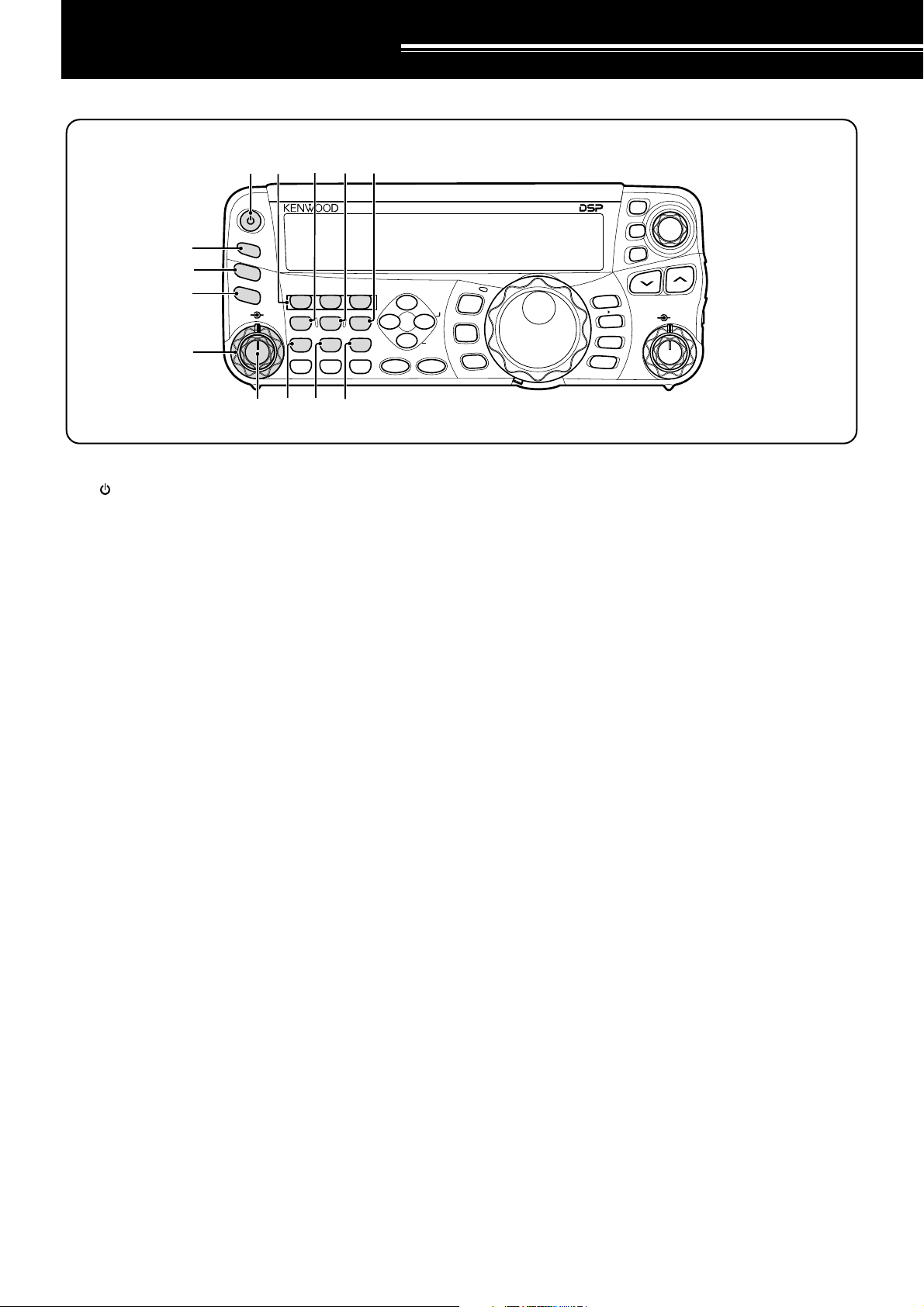
q [ ] (POWER) switch
Press and hold briefly to switch the transceiver power
ON. Press again to switch the power OFF {page 18}.
w PF key
You can assign a function to this Programmable
Function key. The default function is VOICE1.
To use the Voice Guide and Storage functions, the
optional VGS-1 is required {page 64}.
e ATT/PRE/ ANT1/2 key
Press to cycle between receiver attenuator ON, preamplifier ON and OFF {pages 49, 61}.
Press and hold for 1 second, then release it to select
either ANT 1 or ANT 2 {page 60}.
r AT
Press to activate the internal antenna tuner {page 60}
or an external antenna tuner. Press and hold to start
tuning the automatic antenna tuner.
t SQL control
Used for muting (“squelching”) the speaker, the head
phones and the AF output on DATA (8-pin mini DIN
connector) when no receive signal is present on the
transceiver {page 19}.
y AF control
Turn to adjust the audio volume on the transceiver
{page 18}.
u CH1/ 1/ REC, CH2/ 2/ REC, CH3/ 3/ REC key
Press to play back the CW or voice messages (the
VGS-1 is required) {page 40}. Press and hold to
record the voice messages (the VGS-1 is required)
{page 68} or CW messages that are associated with
the internal electronic keyer {page 40}.
i PWR/ 4/ TX MONI key
Press to adjust the transmission output power.
Press and hold to adjust the volume of the
transmission signal monitor function {page 65}.
HF/50MHz ALL MODE TRANSCEIVER TS-480
MODE
NAR
F.LOCK
MENU
CW.T
MHz
o
MIC/ 5/ RF.G key
Press to adjust the microphone gain {page 27}.
While the Speech Processor function is ON, press to
adjust the Speech Processor output level {page 37}.
Press and hold to adjust the receiver RF gain
{page 18}.
!0 KEY/ 6/ DELAY key
Press to adjust the internal electronic keyer speed.
Press and hold to adjust the VOX delay time {page
36} or Break-in time (Full Break-in/ Semi Break-in
time) for CW mode {page 39}.
!1 NB/T/ 7 key
Press to switch the Noise Blanker ON or OFF. Press
and hold to adjust the Noise Blanker level {page 47}.
In FM mode, press to turn the Tone function ON or
OFF {page 32}. Press and hold to select a sub-audible
tone for the Tone funtion {page 32}.
!2 VOX/ 8 key
In voice mode, press to turn the VOX (VoiceOperated Transmit) function ON or OFF {page 36}.
In CW mode, press to turn the Break-in function ON
or OFF {page 39}. Press and hold to adjust the
microphone input gain for VOX operation. The VOX
icon appears when the VOX (Voice)/ Break-in (CW)
function is active.
!3 PROC/ 9 key
Press to turn the Speech Processor ON or OFF
{page 37}. Press and hold to adjust the Speech
Processor input level. The PROC icon appears when
the Speech Processor function is ON.
M.IN
A=B
QMI
M VFO
QMR
M/V
A / B
SPLIT
XIT
CL
RIT
MULTI
TF-SET
IF
SHIFT
10
Page 19
!9
@0
@1
@2
3 GETTING ACQUAINTED
@3
PF
ANT 1/2
ATT/PRE
AT
AF SQL
1 REC 2 REC
CH1 CH2 CH3
4
TX MONI
PWR
7
NB/T
CLR
MTR
5 RF.G
MIC KEY
8
VOX
0 OFF
AGC
3 REC
6
DELAY
9
PROC
ENT
DNL
NR FIL
BC
STEP SG.SEL
FINE SCAN
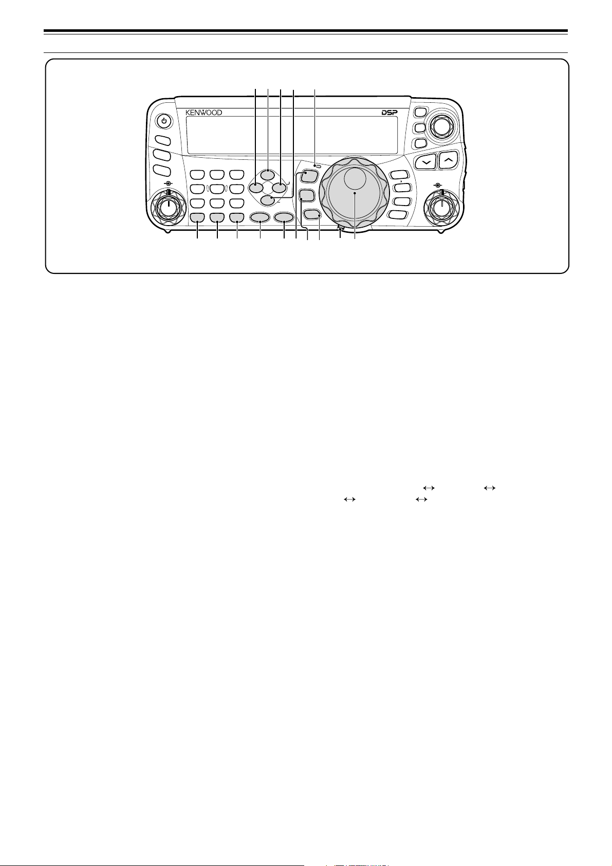
!4 MTR/ CLR key
Press to select the meter scales {page 20} or exit
from, abort, or reset various functions. Press and
hold to clear memory channels {page 54}.
!5 AGC/ 0/ OFF key
Press to toggle the fast or slow response time for the
Automatic Gain Control (AGC). Press and hold to
switch the AGC OFF {page 35}.
!6 ENT key
Press to enter your desired frequency using the
keypad {page 34} or lock out memory channels from
the scan list {page 54}.
!7 FINE/ STEP key
Press to activate the Fine tuning function to allow
more precise tuning {page 35}. Press and hold to
select the frequency step size for the MULTI control
{page 34}.
!8 SCAN/ SG.SEL key
Press to start or stop the Scan function {page 56}.
Press and hold to select a Scan group {page 59}.
!9 NR key
Press to select the DSP Noise Reduction function,
NR1, NR2 or OFF {page 47}. When the Noise
Reduction function is turned ON, press and hold key
to change the parameter of the Noise Reduction
function {page 47}.
@0 DNL key
Press to turn the DNL (Digital Noise Limiter) function
ON or OFF. The “DNL” icon appears when it is ON.
Press and hold the key to change the level of DNL
function {page 47}.
@1 FIL/ NAR key
Press to configure the low-cut and high-cut filter
frequency for the DSP filter (AF). Press and hold to
select the narrow IF filter if available {page 45}.
HF/50MHz ALL MODE TRANSCEIVER TS-480
MODE
NAR
F.LOCK
MENU
CW.T
MHz
@4!4 !5 !6 !7 !8
@6
@5
@7
@8
@2 BC/ CW.T key
Press to select the DSP Beat Cancel funtion, BC1
(Beat Cancel 1), BC2 (Beat Cancel 2) or OFF
{page 47}. In CW mode, press to start the Auto Zerobeat in CW mode {page 29}.
@3 LED
Lights red when the transceiver is transmitting, lights
green when the transceiver is receiving signals, and
turns OFF when the transceiver mutes with the
squelch function.
@4 MODE key
Press to change the operating mode pair. There are
4 pairs: USB/ LSB, CW/ CWR, FSK/ FSR, and AM/ FM.
Press and hold for a second to toggle the mode
within each pair: USB LSB, CW CWR,
FSK FSR, or AM FM {page 19}.
@5 MENU/ F.LOCK key
Press to enter Menu mode {page 22}. Press and hold
to activate the Frequency Lock function {page 63}.
@6 MHz key
Press to turn the MHz Up/ Down function ON or OFF.
The MHz digit increases or decreases when you turn
the MULTI control. Press and hold to change the
increment/ decrement step value {page 34}.
@7 Tuning control torque adjustment lever
The lever behind the Tuning control adjusts the
control torque level; turn clockwise for light torque or
counterclockwise for heavy torque.
@8 Tuning control
Turn to select the desired frequency {page 19}.
Use the convenient finger-tip cavity for continuous
tuning.
M.IN
A=B
QMI
M VFO
QMR
A / B
SPLIT
CL
XIT
RIT
TF-SET
MULTIIFSHIFT
M/V
11
Page 20
3 GETTING ACQUAINTED
#8
#7
#6
PF
ANT 1/2
ATT/PRE
AT
AF SQL
1 REC 2 REC
CH1 CH2 CH3
4
TX MONI
PWR
7
NB/T
CLR
MTR
5 RF.G
MIC KEY
8
VOX
0 OFF
AGC
3 REC
6
DELAY
9
PROC
ENT
DNL
NR FIL
BC
STEP SG.SEL
FINE SCAN
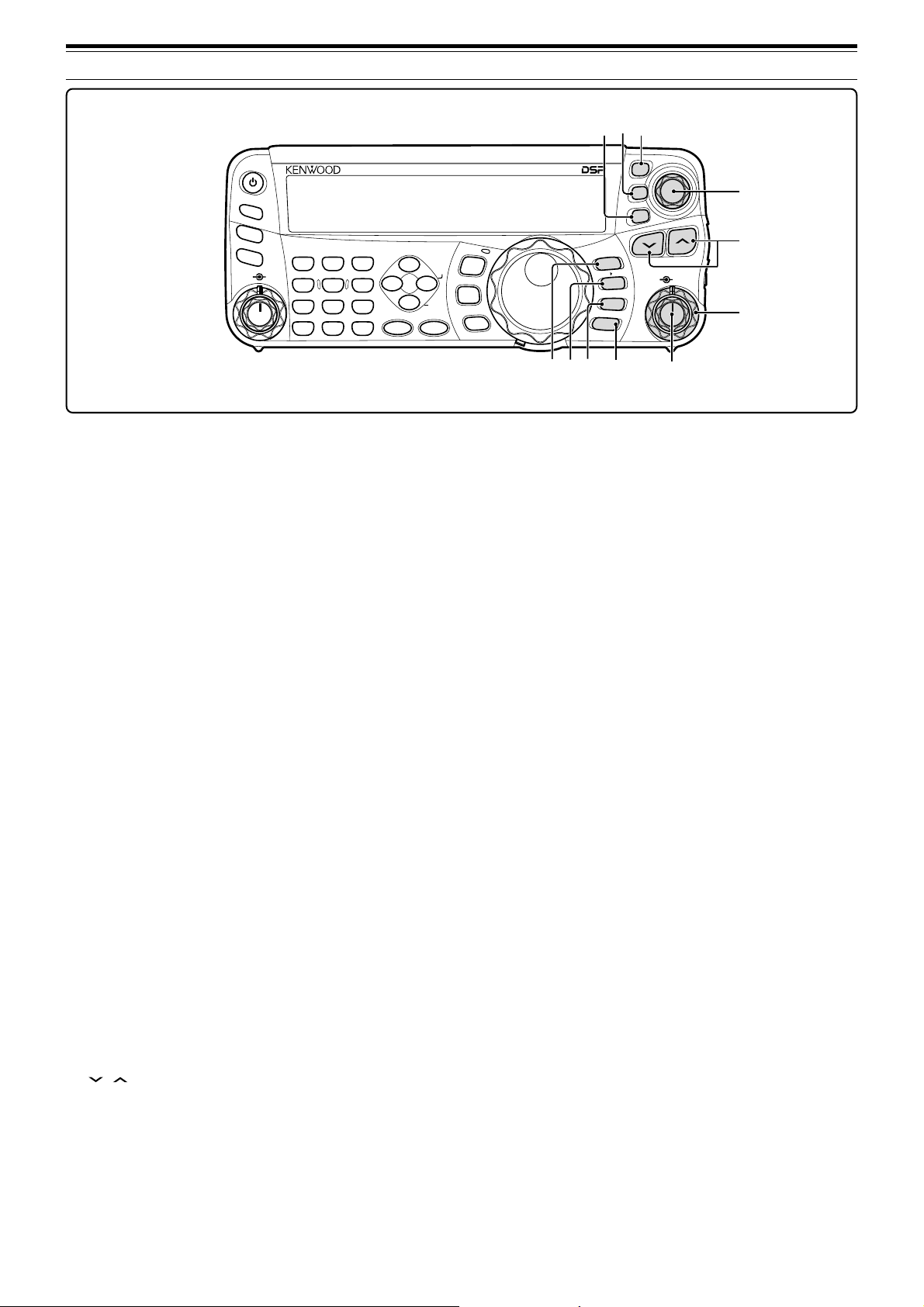
@9 QMI/ M.IN key
Press to store data to the Quick Memory. Press and
hold to store the current operating frequencies and
other data to the Memory channel.
ss
s
#0 QMR/ M
ss
VFO key
Press to recall data from the Quick Memory
{page 55}. Press and hold to transfer the Memory
Channel frequencies and other data to the VFO.
#1 A/B / M/V key
Press to select either VFO A or VFO B {page 18}.
Press and hold to toggle between Memory and VFO
modes.
#2 A=B/ SPLIT key
Press to duplicate the data in the currently selected
VFO to the other VFO {page 35}. Press and hold to
enter split-frequency operation which allows you to
use different transmission and reception frequencies
{page 30}.
#3 MULTI control
In VFO mode, rotate to step the operating frequency
up or down {page 34}. In Memory Channel mode,
rotate to select a Memory Channel {page 51}.
Also, used for selecting Menu numbers when
accessing the Menu mode {page 22} and as a
selector to choose settings for various functions
activated by Remote Control panel keys.
#4 IF SHIFT control
Rotate to shift the center frequency of the IF passband
either lower or higher, to remove interference {page
45}.
#5 / key
Normally, press to step through all the Amateur radio
bands consecutively {page 19}. Also used to make
selections from the Menu {page 22} and to check the
Start and End frequencies of the Scan function
{page 53}. When both the split-frequency and the
frequency lock function are actived, press and hold to
perform the TF-SET function {page 30}.
HF/50MHz ALL MODE TRANSCEIVER TS-480
MODE
NAR
F.LOCK
MENU
CW.T
MHz
@9 #0 #3
#6 CL key
Press to clear the RIT/ XIT frequency to zero
{pages 35, 37}.
#7 XIT key
Press to turn the XIT (Transmit Incremental Tuning)
function ON or OFF {page 37}. When the XIT
function is ON, the XIT icon appears.
#8 RIT key
Press to turn the RIT (Receive Incremental Tuning)
function ON or OFF {page 35}. When the RIT
function is ON, the RIT icon appears.
#9 RIT/ XIT control
When the RIT/ XIT function is ON, turn to adjust the
offset frequency. The RIT/ XIT offset frequency
appears on the sub-display {pages 35, 37}.
#1
M.IN
A=B
QMI
M VFO
QMR
M/V
A / B
SPLIT
#2
CL
XIT
RIT
TF-SET
MULTIIFSHIFT
#9
#5
#4
12
Page 21
LCD DISPLAY
q w e r t y u o!0 !1 !4 !5 !6 !7 !8!9i !2 !3
3 GETTING ACQUAINTED
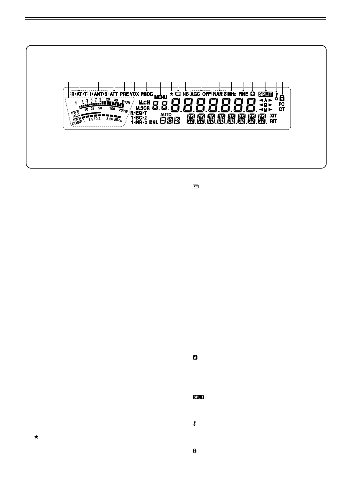
q METER
While receiving, serves as an S-meter to measure
and display the received signal strength. While
transmitting, serves as a power meter plus an ALC
meter, an SWR meter, or a Speech Processor
compression meter. The Peak Hold function holds
each reading for approximately half a second.
w RtATsT
Appears while the internal antenna tuner {page 60} or
an external antenna tuner is in-line for the operation.
e 1tANTs2
Either “1tANT” or “ANTs2” appears, depending on
which antenna connector is selected for the operation
{page 60}.
r ATT
Appears when the receiver’s attenuator (approx.
12 dB) is ON {pages 49, 61}.
t PRE
Appears when the receiver pre-amplifier (approx.
6 dB) is ON {page 49}.
y VOX
Appears when the VOX (Voice Operated
Transmission) function is ON or the Break-in function
is ON for the CW mode {pages 36, 39}.
u PROC
Appears when the Speech Processor function is ON
{page 37}.
i MENU
Appears when configuring the parameters in the
Menu mode {page 22}.
o
Reserved for future updates.
!0
Appears while the Constant Recording function is
working {page 69}.
!1 NB
Appears when the Noise Blanker is ON {page 47}.
!2 AGC OFF
“AGC - F” (fast) or “AGC” (slow) appears when the
AGC (Automatic Gain Control) function is ON. “AGC
OFF” appears when the AGC is OFF {page 35}.
!3 NAR 2
“NAR” appears when the narrow IF filter is selected
for the operating mode. If 2 optional IF filters are
installed and the transceiver selects the secondary IF
filter, “NAR 2” appears {page 45}.
!4 MHz
Appears when the MHz Up/ Down mode using the
MULTI control is ON {page 34}. It also appears when
the Quick Menu function is ON {page 22}.
!5 FINE
Appears when the Fine function is ON {page 35}.
!6
Appears when the selected Menu No. is in the Quick
Menu list. It also appears when the transceiver is
scanning the frequencies between the slow down
frequency points {page 57}.
!7
Appears when the split-frequency operation is ON
{page 30}.
!8
Appears when the Tuning control Lock function is ON
{page 63}.
!9
Appears when the Frequency Lock function is ON
{page 63}.
13
Page 22
3 GETTING ACQUAINTED
#7
#6
#5
#4
@0@1@2
tt
ss
t
s
tt
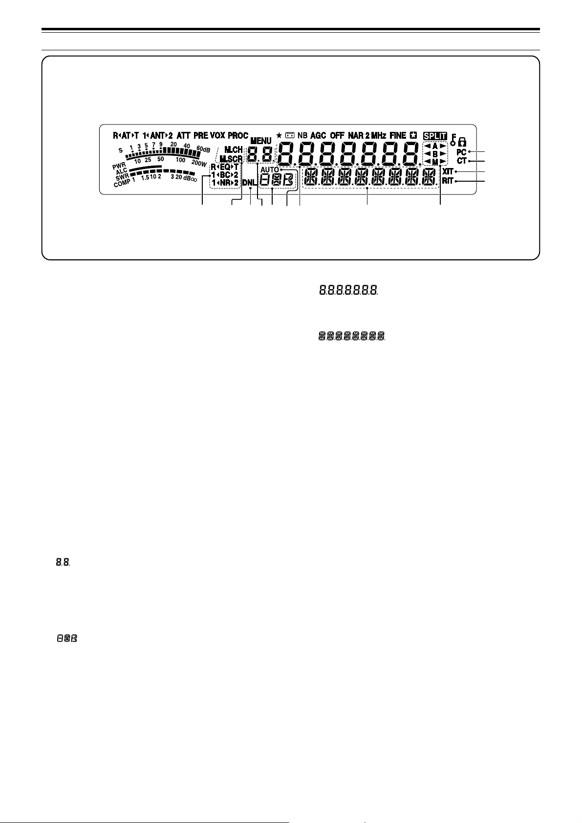
@0 R
tt
t
tt
“R
ON {page 64}. “EQ
ss
EQ
T
EQ” appears when the RX Equalizer function is
ss
s
ss
T” appears when the TX
@3@4
@6
Equalizer function is ON {page 38}.
@1 1tBCs2
ss
s
“1tBC” or “BC
ss
2” appears, as you select the DSP
Beat Cancel 1 or Beat Cancel 2 {page 47}.
tt
ss
t
s
tt
@2 1
tt
t
tt
“1
ss
NR
2
NR” or “NR
ss
s
ss
2” appears, depending on whether
DSP Noise Reduction 1 (Line Enhanced method) or
Noise Reduction 2 (SPAC method) is selected
{page 47}.
@3 M.CH
Appears in Memory Recall mode {page 51}.
@4 M.SCR
Appears in Memory Scroll mode {page 52}.
@5 DNL
Appears when the Digital Noise Limiter function is ON
{page 47}.
@6
Shows the Memory Channel number for the
transceiver. In Menu mode, it displays the Menu No.
In Quick Memory mode, it shows the Quick Memory
number location (the Quick Memory number ranges
from “0_” to “9_”) {page 55}.
@7
Displays a communication mode {page 19}.
@8 AUTO
Appears when Auto Mode function is ON {page 61}.
#0@9@8@7@5
#1#2#3
@9
The transceiver operating frequency display. In Menu
mode, it displays the parameters.
#0
In the normal operating mode, it displays the
transceiver status and Menu item descriptions when
necessary. While the RIT, XIT or SPLIT function is
turned ON, it is used to display the frequency
information for these functions {pages 35, 37}.
#1 tA
s
“tA” or “As” appears while VFO A is selected
{pages 18, 30}. “A” appears while Menu A is being
accessed in the Menu mode {page 22}.
#2 tB
s
“tB” or “Bs” appears while VFO B is selected
{pages 18, 30}. “B” appears while Menu B is being
accessed in the Menu mode {page 22}.
#3tM
s
“tM” or “Ms” appears while a simplex memory
channel is selected {page 50}.
#4 RIT
Appears when Receive Incremental Tuning function is
ON {page 35}.
#5 XIT
Appears when Transmit Incremental Tuning function
is ON {page 37}.
#6 CT
“T” appears when the Tone function is ON {page 32}.
“CT” appears when the CTCSS (Continuous Tone
Coded Squelch System) is ON {page 33}.
#7 PC
Appears when the transceiver is being controlled by a
PC {page 67}.
14
Page 23
TX/ RX UNIT
3 GETTING ACQUAINTED
i
qw ert y
EXT.SP DATA REMOTE
MIC
PADDLE KEY
PANEL
u
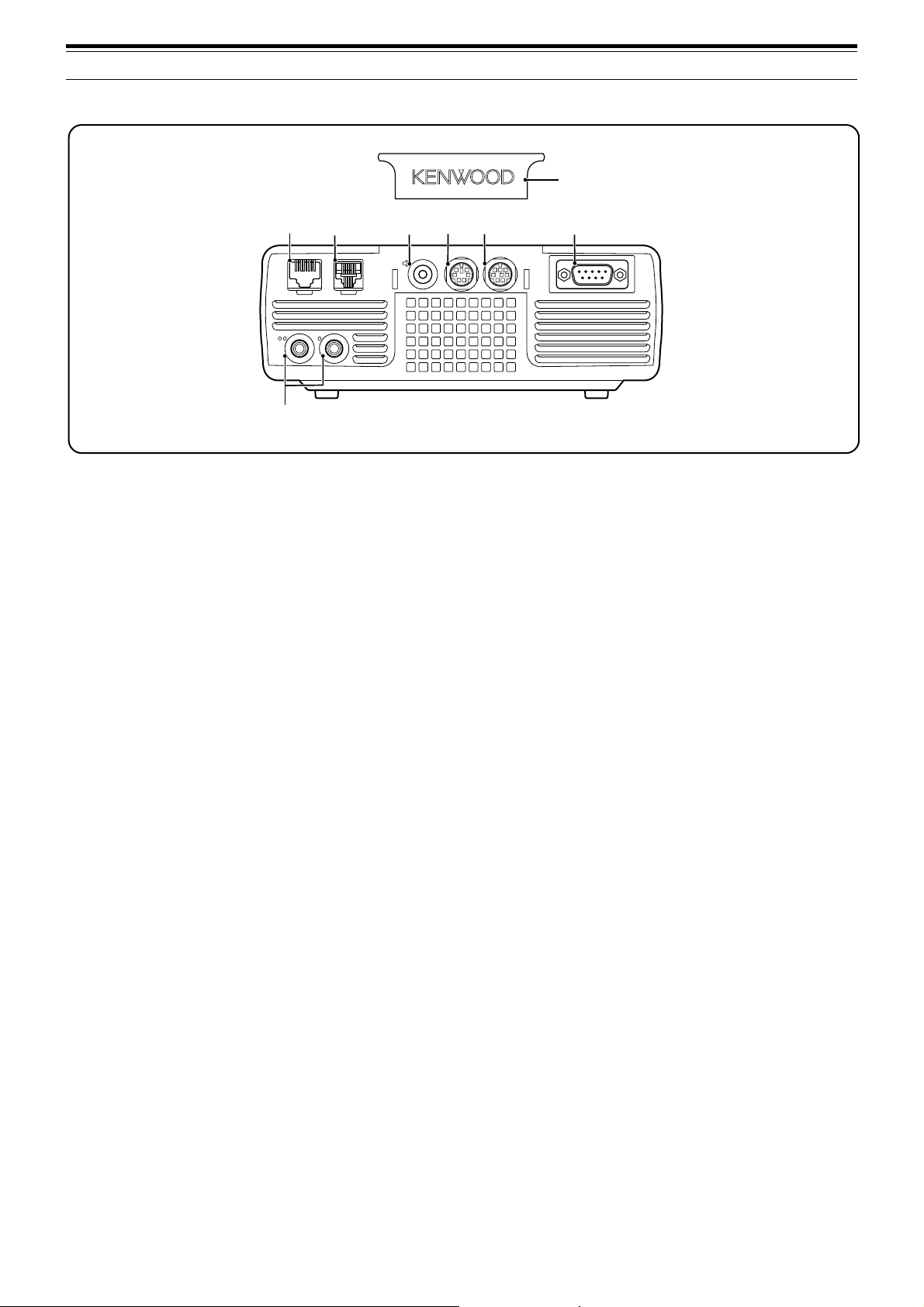
q MIC connector
Connect a cable from the supplied microphone to this
connector {page 6}.
w PANEL connector
Connect a cable from the Remote Control panel to
this connector {page 6}.
e EXT.SP jack
Mate with a 3.5 mm (1/8"), 2-conductor (mono) plug
for connecting an external speaker {page 7}.
r DATA connector
Mates with a 6-pin male DIN connector for connecting
various accessory equipment, such as an external
TNC/ MCP or a RTTY terminal {pages 77, 78}.
t REMOTE connector
Mates with a 6-pin male mini DIN connector for
connecting an HF/ 50 MHz linear amplifier {page 77}.
y COM connector
Mates with a DB-9 female connector for connecting a
computer via one of its serial communication (COM)
ports {page 67}. Also used with the Quick Data
Transfer function {pages 66, 76} and DX
PacketCluster Tune function {pages 72, 79}.
u PADDLE and KEY jacks
The PADDLE jack mates with a 6.3 mm (1/4")
3-conductor plug for connecting a keyer paddle to the
internal electronic keyer. The KEY jack mates with a
3.5 mm (1/8") 2-conductor plug for connecting an
external key for CW operation. Refer to “Keys for
CW (PANEL and KEY)” {page 7} before using these
jacks.
i Plastic cover
If the EXT.SP jack, DATA connector and REMOTE
connector are not used, attach this cover to protect
the connectors from dust.
COM
15
Page 24
3 GETTING ACQUAINTED
ANT 1ANT 2
q
w
t
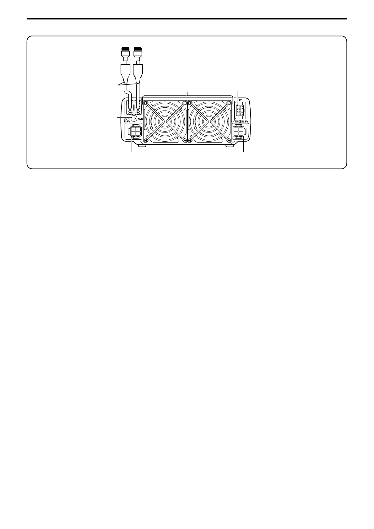
q ANT 1 and ANT 2 connectors
Connect your primary HF/ 50 MHz antenna to ANT 1
connector. If you are using 2 antennas for the HF/ 50
MHz band, connect the secondary antenna to the ANT
2 connector.
w GND post
Connect a heavy gauge wire or copper strap between
the ground post and the nearest earth ground or vehicle
body {pages 2, 4}.
e Cooling Fans
The TS-480SAT is equipped with 1 cooling fan.
The TS-480HX is equipped with 2 cooling fans.
Air flows in from these fans.
r AT connector
Mates with the connecter from the cable supplied with
the AT-300 external antenna tuner. Refer to the
instruction manual supplied with the tuner for more
information.
t DC 1 13.8 V DC power input connector
Connect a primary 13.8 V DC power source to this
connector {pages 2, 3}. Use the DC cable supplied
with the transceiver.
y DC 2 13.8 V DC power input connector
(TS-480HX only)
You must connect a secondary 13.8 V DC power
source to this connector in order to transmit
{pages 2, 3}. Use the cable supplied with the
transceiver. If no DC power source is available on
this connector, you cannot transmit at any output
power. However, you can still receive {page 18}.
e
r
y
16
Page 25
REMOTE CONTROL PANEL (REAR)
3 GETTING ACQUAINTED
q
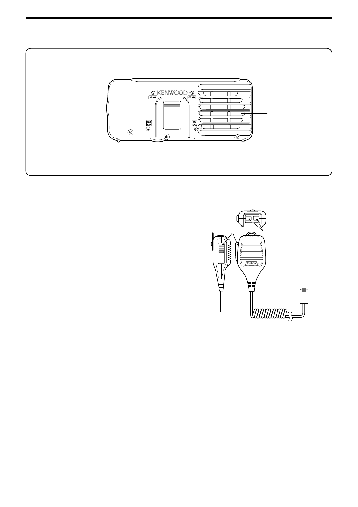
q Speaker
When the headphones are connected, the
speaker mutes.
If you wish to use a commercially available 3rd party
angle or mount, there are 4 screw holes available on
the rear of the Remote Control panel so that you can
mount it to the angle or mount. Use 3 mm x 8 mm
tapping screws to mount the panel securely to the
angle or mount. (The tapping screws are not
supplied).
MICROPHONE
DWN UP
q
PTT
q PTT (Push-to-Talk) switch
The transceiver is placed in Transmission mode when
this non-locking switch is held down. Releasing the
switch returns the transceiver to Reception mode.
w
w UP/ DWN keys
Use these keys to step the VFO frequency, Memory
Channels, or Menu selections up and down.
Press and hold these keys to continuously change
the settings.
17
Page 26
OPERATING BASICS
NAR
1 REC 2 REC
5 RF.G
0 OFF
8
3 REC
9
4
7
TX MONI6DELAY
HF/50MHz ALL MODE TRANSCEIVER TS-480
CLR
STEP SG.SEL
CW.T
F.LOCK
M/V
SPLIT
M VFO
M.IN
TF-SET
MULTIIFSHIFT
AF SQL
PF
AT
CH1 CH2 CH3
PWR
MIC KEY
VOX
PROC
AGC
ENT
A / B
A=B
MODE
MHz
QMI
QMR
MENU
MTR
NB/T
ANT 1/2
FINE SCAN
DNL
BC
NR FIL
RIT
XIT
CL
ATT/PRE
NAR
1 REC 2 REC
5 RF.G
0 OFF
8
3 REC
9
4
7
TX MONI6DELAY
HF/50MHz ALL MODE TRANSCEIVER TS-480
CLR
STEP SG.SEL
CW.T
F.LOCK
M/V
SPLIT
MVFO
M.IN
TF-SET
MULTIIFSHIFT
AF SQL
PF
AT
CH1 CH2 CH3
PWR
MIC KEY
VOX
PROC
AGC
ENT
A / B
A=B
MODE
MHz
QMI
QMR
MENU
MTR
NB/T
ANT 1/2
FINE SCAN
DNL
BC
NR FIL
RIT
XIT
CL
ATT/PRE
SWITCHING POWER ON/ OFF
1 Switch the DC power supply(s) ON if you are
using a DC power supply(s).
2 Press and hold [ ] (POWER) briefly to switch
the transceiver ON.
HF/50MHz ALL MODE TRANSCEIVER TS-480
PF
ANT 1/2
ATT/PRE
1 REC 2 REC
3 REC
AT
AF SQL
CH1 CH2 CH3
TX MONI6DELAY
4
PWR
7
NB/T
CLR
MTR
5 RF.G
MIC KEY
8
VOX
0 OFF
AGC
DNL
MODE
NAR
F.LOCK
NR FIL
PROC
ENT
BC
STEP SG.SEL
FINE SCAN
MENU
CW.T
MHz
9
• Do not press the switch for more than
approximately 2 seconds; the transceiver will
be switched OFF.
• TS-480HX only: If “RX ONLY” appears on the
sub-display upon power up, confirm that two
DC cable connectors are securely connected to
the DC-1 and DC-2 connectors. When this
warning message appears, you can receive
signals as usual but you cannot transmit even if
you decrease the output power. “TWIN PWR”
appears when two DC power cables are
connected to the DC-1 and DC-2 connectors.
• Upon power up, “HELLO” appears on the main
display, followed by the selected frequency and
other indicators.
CL
XIT
RIT
M.IN
QMI
M VFO
MULTIIFSHIFT
QMR
M/V
A / B
SPLIT
A=B
RF (RADIO FREQUENCY) GAIN
The RF gain is normally configured to the maximum
level regardless of the operating modes. The
transceiver has been configured to the maximum
level at the factory. However, you may decrease the
RF gain slightly when you have trouble hearing the
desired signal because of excessive atmospheric
noise or interference from other stations. First, take
note of the peak S-meter reading of the desired
signal.
TF-SET
1 Press [MIC/ RF.G] (1 s).
• The current RF gain level appears on the
sub-display (0: minimum ~ 100: maximum).
2 Turn the MULTI control counterclockwise until the
S-meter reads the peak value that you noted.
3 To switch the transceiver OFF, press [ ]
(POWER) again.
4 Switch the DC power supply(s) OFF.
•You may skip step 3. After switching the
transceiver ON, you can switch it OFF or ON
using only the power switch of the DC power
supply(s). The transceiver remembers the
information of the POWER switch position
when the DC power source is switched OFF.
ADJUSTING VOLUME
AF (AUDIO FREQUENCY) GAIN
Turn the AF control clockwise to increase the audio
level and counterclockwise to decrease the level.
AF SQL
Note:
The position of the
PF
ANT 1/2
ATT/PRE
1 REC 2 REC
AT
CH1 CH2 CH3
TX MONI6DELAY
5 RF.G
4
AF SQL
MIC KEY
PWR
7
8
VOX
NB/T
CLR
0 OFF
AGC
MTR
AF
control does not affect the volume of
3 REC
9
PROC
ENT
HF/50MHz ALL MODE TRANSCEIVER TS-480
DNL
NAR
NR FIL
BC
CW.T
STEP SG.SEL
FINE SCAN
MODE
F.LOCK
MENU
MHz
beeps caused by pressing keys nor the CW TX sidetone. The audio
level for Digital mode operation is also independent of the
setting.
M.IN
QMI
MVFO
QMR
A / B
SPLIT
A=B
AF
CL
XIT
RIT
MULTIIFSHIFT
M/V
control
TF-SET
• Signals that are weaker than this level will be
attenuated and reception of the station will
become easier.
Depending on the type and gain of your antenna, and
the condition of the band, adjust the RF gain. When
using FM mode, always adjust the RF gain to the
maximum level.
SELECTING VFO A OR VFO B
Two VFOs are available for controlling the frequency
on the transceiver. Each VFO (VFO A and VFO B)
works independently so that a different frequency and
mode can be selected. For example, when SPLIT
operation is activated, VFO A is used for reception
and VFO B is used for transmission. The opposite
combination is also possible.
Press [A/B / M/V] to toggle between VFO A and B.
CL
XIT
RIT
M.IN
TF-SET
QMI
M VFO
MULTIIFSHIFT
QMR
M/V
A / B
SPLIT
A=B
PF
ANT 1/2
ATT/PRE
AT
AF SQL
1 REC 2 REC
CH1 CH2 CH3
TX MONI6DELAY
5 RF.G
4
MIC KEY
PWR
7
8
VOX
NB/T
CLR
0 OFF
AGC
MTR
3 REC
9
PROC
ENT
HF/50MHz ALL MODE TRANSCEIVER TS-480
DNL
NAR
NR FIL
BC
CW.T
STEP SG.SEL
FINE SCAN
MODE
F.LOCK
MENU
MHz
18
•“tA” or “tB” appears to indicate which VFO is
selected.
Page 27
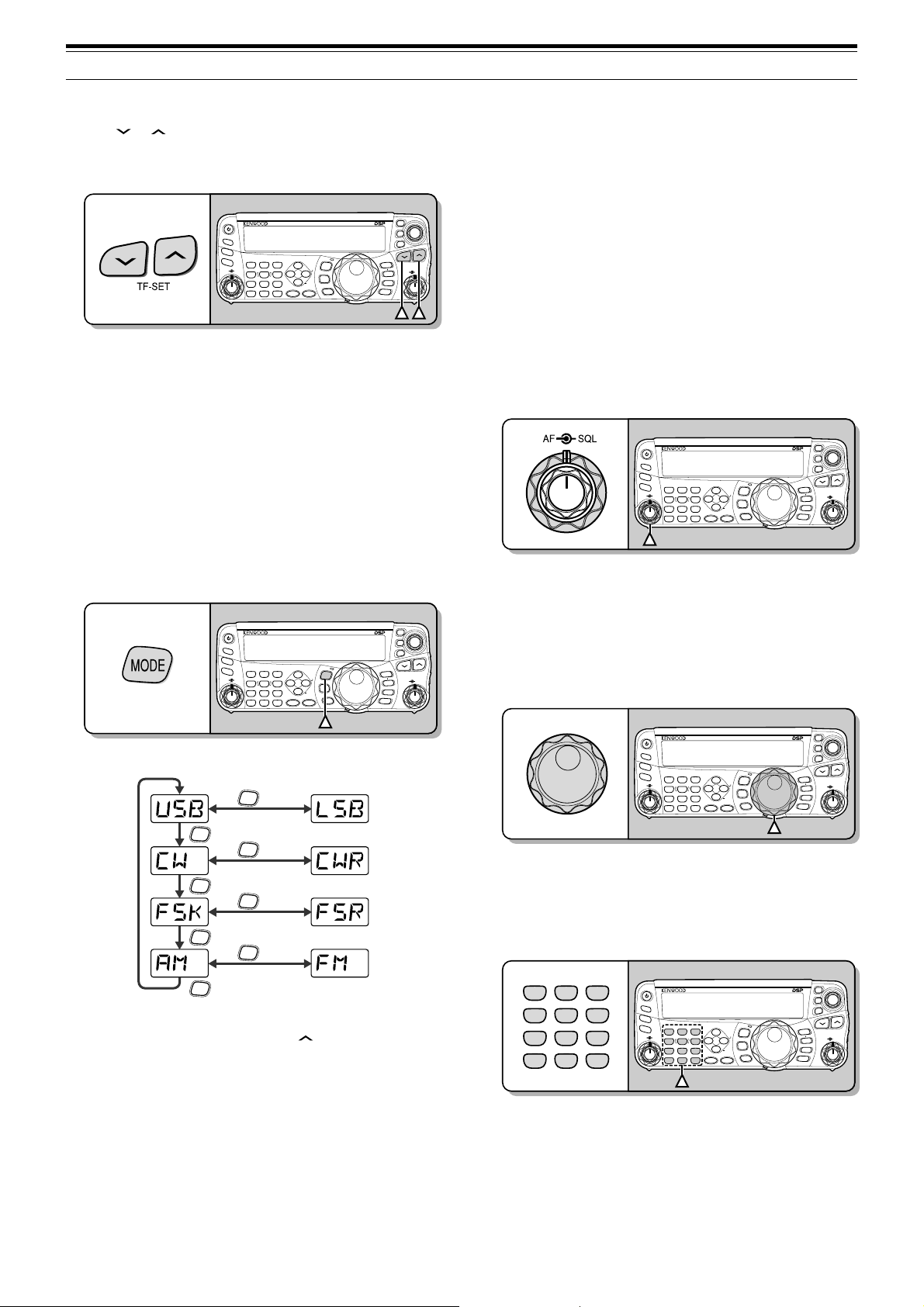
4 OPERATING BASICS
NAR
1 REC 2 REC
5 RF.G
0 OFF
8
3 REC
9
4
7
TX MONI6DELAY
HF/50MHz ALL MODE TRANSCEIVER TS-480
CLR
STEP SG.SEL
CW.T
F.LOCK
M/V
SPLIT
M VFO
M.IN
TF-SET
MULTIIFSHIFT
AF SQL
PF
AT
CH1 CH2 CH3
PWR
MIC KEY
VOX
PROC
AGC
ENT
A / B
A=B
MODE
MHz
QMI
QMR
MENU
MTR
NB/T
ANT 1/2
FINE SCAN
DNL
BC
NR FIL
RIT
XIT
CL
ATT/PRE
1 REC 2 REC
5 RF.G
0 OFF
8
3 REC
9
4
7
TX MONI
6
DELAY
CLR
CH1 CH2 CH3
PWR
MIC KEY
VOX
PROC
AGC
ENT
MTR
NB/T
SELECTING A BAND
Press [ ]/ [ ] to select your desired band.
• Holding down either key changes the bands
continuously.
CL
XIT
RIT
M.IN
TF-SET
QMI
M VFO
MULTIIFSHIFT
QMR
M/V
A / B
SPLIT
A=B
ANT 1/2
PF
ATT/PRE
AT
AF SQL
1 REC 2 REC
CH1 CH2 CH3
TX MONI6DELAY
5 RF.G
4
MIC KEY
PWR
7
8
VOX
NB/T
CLR
0 OFF
AGC
MTR
3 REC
9
PROC
ENT
HF/50MHz ALL MODE TRANSCEIVER TS-480
DNL
NAR
NR FIL
BC
CW.T
STEP SG.SEL
FINE SCAN
MODE
F.LOCK
MENU
MHz
SELECTING A MODE
Press [MODE] to cycle through the 4 mode pairs:
USB/ LSB, CW/ CWR, FSK/ FSR, and AM/ FM. Each
time you press [MODE], the mode display cycles
USB or LSB, CW or CWR, FSK or FSR, FM or AM.
To select the other mode on each pair, press [MODE]
(1 s). For example, to select “LSB” while “USB” is
visible, press [MODE] (1 s). “USB” changes to
“LSB”. Press [MODE] (1 s) again to go back to
“LSB” from “USB”. The following illustration
describes how to access each mode with the [MODE]
key.
CL
XIT
RIT
M.IN
TF-SET
QMI
MVFO
MULTIIFSHIFT
QMR
M/V
A / B
SPLIT
A=B
ANT 1/2
PF
ATT/PRE
AT
AF SQL
1 REC 2 REC
CH1 CH2 CH3
TX MONI6DELAY
5 RF.G
4
MIC KEY
PWR
7
8
VOX
NB/T
CLR
0 OFF
AGC
MTR
3 REC
9
PROC
ENT
HF/50MHz ALL MODE TRANSCEIVER TS-480
DNL
NAR
NR FIL
BC
CW.T
STEP SG.SEL
FINE SCAN
MODE
F.LOCK
MENU
MHz
ADJUSTING SQUELCH
The purpose of the Squelch is to mute the speaker
when no signals are present. With the squelch level
correctly set, you will hear sound only while actually
receiving signals. The higher the selected squelch
level, the stronger the signals must be to receive.
The appropriate squelch level depends on the
ambient RF noise conditions.
Turn the SQL control when there are no signals
present to select the squelch level at which the
background noise is just eliminated; the green LED
will turn off. Many ham operators prefer leaving the
SQL control fully counterclockwise unless operating
on a full-carrier mode such as FM. The squelch
level for the main transceiver is preset at the factory
to approximately the 9 o’clock position for FM and 11
o’clock for SSB and AM.
SELECTING A FREQUENCY
Turn the Tuning control clockwise or press Mic [UP]
to increase the frequency. Turn the Tuning control
counterclockwise or press Mic [DWN] to decrease the
frequency.
MODE
(1 s)
MODE
MODE
(1 s)
MODE
MODE
(1 s)
MODE
MODE
(1 s)
MODE
Access Menu No. 02 then press [ ] to select “on” to
turn the Auto Mode selection ON. When it is ON,
“AUTO” appears. As a default setting, if you change
the frequency above or below 9.5 MHz, the
transceiver automatically switches modes; LSB for
frequencies under 9.5 MHz and USB for frequencies
equal to or over 9.5 MHz. You can further add the
frequency table data to change the mode
automatically {page 61}.
You may prefer directly entering a frequency using
the numeric keypad if the desired frequency is far
from the current frequency. Press [ENT], then press
the numeric keys as necessary. For details, refer to
“Direct Frequency Entry” {page 34}.
This transceiver provides many other methods for
quickly selecting a frequency. For further information,
refer to “SELECTING YOUR FREQUENCY”
{page 34}.
19
Page 28
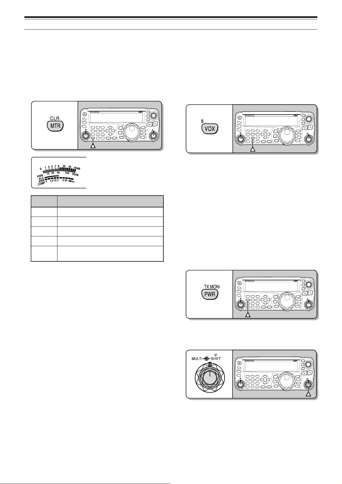
4 OPERATING BASICS
NAR
1 REC 2 REC
5 RF.G
0 OFF
8
3 REC
9
4
7
TX MONI6DELAY
HF/50MHz ALL MODE TRANSCEIVER TS-480
CLR
STEP SG.SEL
CW.T
F.LOCK
M/V
SPLIT
M VFO
M.IN
TF-SET
MULTIIFSHIFT
AF SQL
PF
AT
CH1 CH2 CH3
PWR
MIC KEY
VOX
PROC
AGC
ENT
A / B
A=B
MODE
MHz
QMI
QMR
MENU
MTR
NB/T
ANT 1/2
FINE SCAN
DNL
BC
NR FIL
RIT
XIT
CL
ATT/PRE
NAR
1 REC 2 REC
5 RF.G
0 OFF
8
3 REC
9
4
7
TX MONI6DELAY
HF/50MHz ALL MODE TRANSCEIVER TS-480
CLR
STEP SG.SEL
CW.T
F.LOCK
M/V
SPLIT
M VFO
M.IN
TF-SET
MULTIIFSHIFT
AF SQL
PF
AT
CH1 CH2 CH3
PWR
MIC KEY
VOX
PROC
AGC
ENT
A / B
A=B
MODE
MHz
QMI
QMR
MENU
MTR
NB/T
ANT 1/2
FINE SCAN
DNL
BC
NR FIL
RIT
XIT
CL
ATT/PRE
4
NAR
1 REC 2 REC
5 RF.G
0 OFF
8
3 REC
9
4
7
TX MONI6DELAY
HF/50MHz ALL MODE TRANSCEIVER TS-480
CLR
STEP SG.SEL
CW.T
F.LOCK
M/V
SPLIT
M VFO
M.IN
TF-SET
MULTIIFSHIFT
AF SQL
PF
AT
CH1 CH2 CH3
PWR
MIC KEY
VOX
PROC
AGC
ENT
A / B
A=B
MODE
MHz
QMI
QMR
MENU
MTR
NB/T
ANT 1/2
FINE SCAN
DNL
BC
NR FIL
RIT
XIT
CL
ATT/PRE
MULTI-FUNCTION METER
The multi-function meter measures the parameters in
the table below. The S-meter scale appears when
the transceiver is in reception mode, and the PWR
meter appears when it is in transmission mode.
Each time you press [MTR/ CLR], it cycles between
the ALC, SWR, and COMP meters. Peak readings
for the S-meter, ALC, SWR, COMP, and PWR
functions are held momentarily.
HF/50MHz ALL MODE TRANSCEIVER TS-480
PF
ANT 1/2
ATT/PRE
1 REC 2 REC
CH1 CH2 CH3
TX MONI6DELAY
5 RF.G
4
MIC KEY
PWR
7
8
VOX
NB/T
CLR
0 OFF
AGC
MTR
3 REC
DNL
MODE
NAR
F.LOCK
NR FIL
9
PROC
MENU
BC
CW.T
STEP SG.SEL
MHz
FINE SCAN
ENT
AT
AF SQL
Multi-function meter
reteM ?derusaeMsItahW
S
RWP
slangisdeviecerfohtgnertS
rewoptuptuonoissimsnarT
CLA
RWS
PMOC
Note:
◆
The COMP meter functions only when the Speech Processor is
ON for SSB, FM, or AM mode.
◆
Peak Hold readings cannot be deactivated.
◆
The S-meter responds differently in FM mode, compared to other
modes. This is not a malfunction.
CL
XIT
RIT
M.IN
TF-SET
QMI
MVFO
MULTIIFSHIFT
QMR
M/V
A / B
SPLIT
A=B
sutatslortnoclevelcitamotuA
oitarevawgnidnatsmetsysannetnA
gnisunehwlevelnoisserpmochceepS
}73egap{rossecorPhceepSeht
TRANSMITTING
For voice communications, press and hold Mic [PTT],
then speak into the microphone in your normal tone
of voice. When you finish speaking, release Mic
[PTT] to receive.
To transmit CW, press [VOX/ 8] to switch the Break-in
function ON. “VOX” appears. Close the key or keyer
paddle. Connect a key or keyer paddle {pages 7, 15},
then select CW using [MODE] {page 19}.
For a detailed explanation on transmitting, refer to
“BASIC COMMUNICATIONS”, beginning on page 27.
SELECTING TRANSMISSION POWER
It is wise to select a lower transmission power if
communication is still reliable. This lowers the risk of
interfering with others on the band. When operating
from battery power, selecting a lower transmission
power allows you more operating time before
recharging is necessary. This transceiver allows you
to change the transmission power even while
transmitting.
1 Press [PWR/ 4/ TX MONI].
• The current transmission power appears.
2 Turn the MULTI control counterclockwise to
reduce the power or clockwise to increase the
power.
• The selectable range differs, depending on the
transceiver model, the current band, and the
mode.
3 Press [PWR/ 4/ TX MONI] to complete the setting.
Note:
20
You may access Menu No. 21, and select “on” to change the
step size from 5 W to 1 W {page 65}.
Page 29
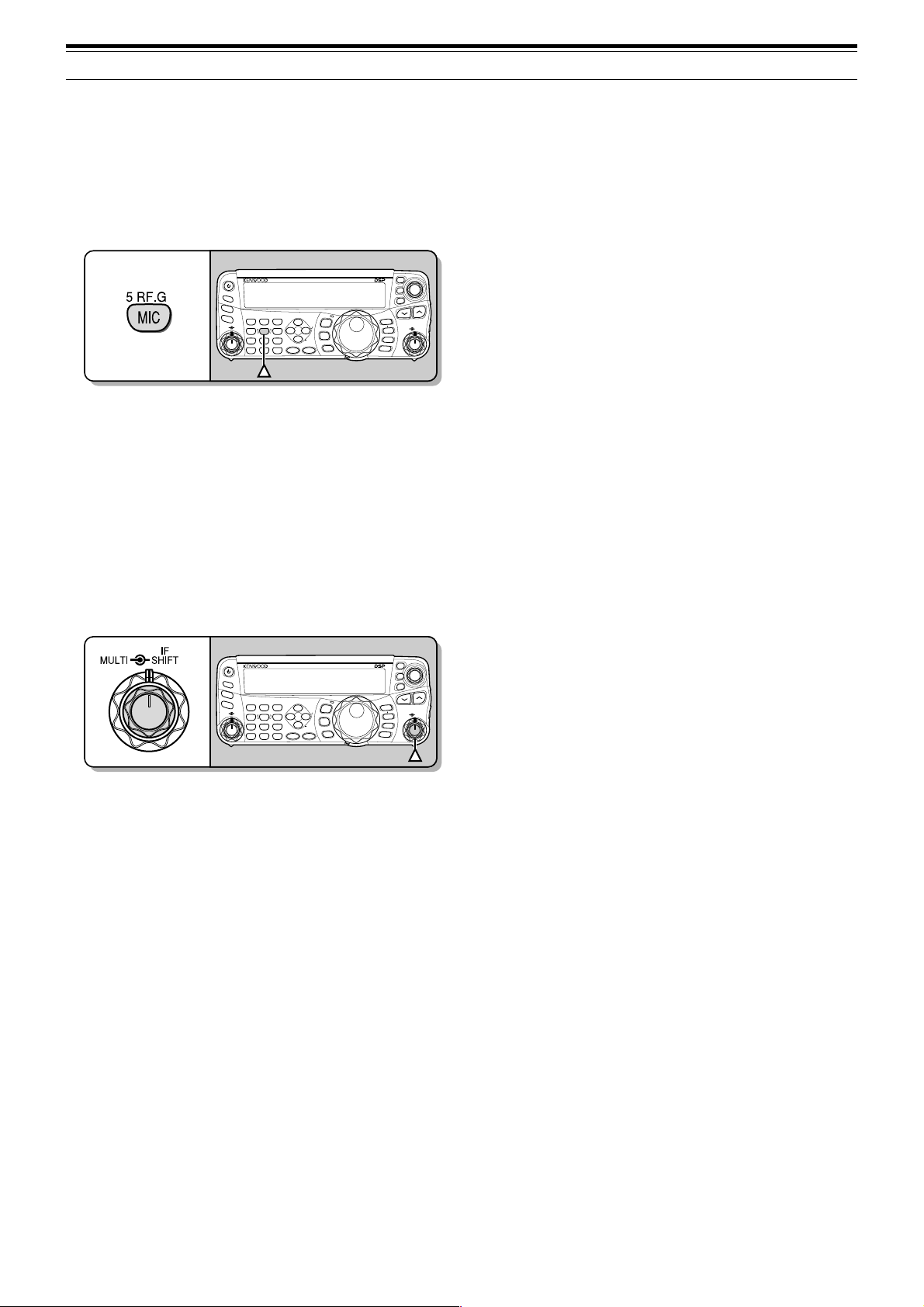
MICROPHONE GAIN
The microphone gain must be adjusted when SSB
or AM mode is selected without using the speech
processor {pages 27, 28}.
1 Press [MIC/ 5/ RF.G].
• The current microphone gain level appears.
The range is from 0 to 100 with a default of 50.
4 OPERATING BASICS
CL
XIT
RIT
M.IN
TF-SET
QMI
MVFO
MULTIIFSHIFT
QMR
M/V
A / B
SPLIT
A=B
ANT 1/2
PF
ATT/PRE
AT
AF SQL
1 REC 2 REC
CH1 CH2 CH3
TX MONI6DELAY
5 RF.G
4
MIC KEY
PWR
7
8
VOX
NB/T
CLR
0 OFF
AGC
MTR
3 REC
9
PROC
ENT
HF/50MHz ALL MODE TRANSCEIVER TS-480
DNL
NAR
NR FIL
BC
CW.T
STEP SG.SEL
FINE SCAN
MODE
F.LOCK
MENU
MHz
2 Press and hold Mic [PTT].
• The LED on the panel lights red.
3 SSB: While speaking into the microphone, adjust
the MULTI control so that the ALC meter reflects
your voice level but does not exceed the ALC limit.
AM: While speaking into the microphone, adjust
the MULTI control so that the power meter slightly
reflects your voice level.
FM: Access Menu No. 44 and select “1” (Normal),
“2” (Medium), or “3” (High) for the microphone
gain if necessary {page 27}.
CL
XIT
RIT
M.IN
TF-SET
QMI
MVFO
MULTIIFSHIFT
QMR
M/V
A / B
SPLIT
A=B
ANT 1/2
PF
ATT/PRE
AT
AF SQL
1 REC 2 REC
CH1 CH2 CH3
TX MONI6DELAY
5 RF.G
4
MIC KEY
PWR
7
8
VOX
NB/T
CLR
0 OFF
AGC
MTR
3 REC
9
PROC
ENT
HF/50MHz ALL MODE TRANSCEIVER TS-480
DNL
NAR
NR FIL
BC
CW.T
STEP SG.SEL
FINE SCAN
MODE
F.LOCK
MENU
MHz
4 Release Mic [PTT] to return to receive.
• The LED lights green or turns off, depending
on the SQL control setting.
Note:
When using the MC-90 microphone with the MJ-88 in FM
mode, select “3” (High) for the microphone gain. The microphone
sensitivity is low in FM mode. This may cause insufficient
modulation. For other microphones, select either “1” (Normal) or “2”
(Medium).
21
Page 30
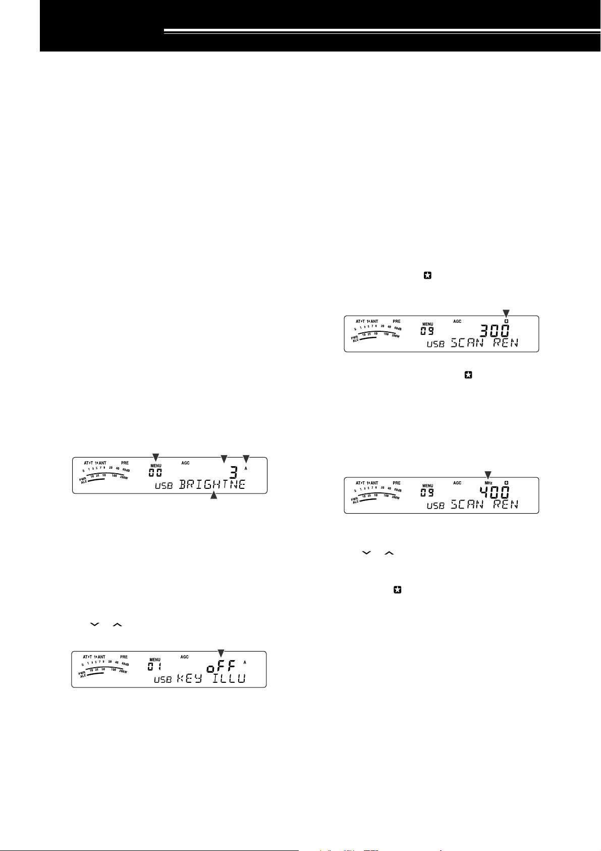
MENU SETUP
WHAT IS A MENU?
Many functions on this transceiver are selected or
configured via a software-controlled Menu, rather
than through the physical controls of the transceiver.
Once familiar with the Menu system, you will
appreciate the versatility it offers. You can customize
the various timings, settings, and programming
functions on this transceiver to meet your needs
without using many controls and switches.
MENU A/ MENU B
This transceiver has 2 menus: Menu A and Menu B.
These menus contain identical functions and can be
configured independently. The transceiver, therefore,
allows you to switch between 2 different
environments quickly and easily. For example, you
can configure Menu A for DXing and contesting while
Menu B is for relaxed local ragchewing. By switching
from Menu A to Menu B, you can instantly change the
Menu configuration and key assignment to suit your
current operating style. Or, 2 operators may share a
single transceiver by dedicating one Menu to each
operator. Both operators can always enjoy their own
configuration.
MENU ACCESS
1 Press [MENU/ F.LOCK].
• The Menu No. and setting appear on the
display, and the explanation of the menu
appears on the sub-display.
QUICK MENU
Because the number of functions this transceiver
provides is extraordinary, there are numerous items in
each Menu. If you find accessing desired Menu Nos.
to be too time consuming, use the Quick Menu to
create your own customized, abbreviated Menu. You
can then add those Menu Nos. which you frequently
use, to the Quick Menu. Copying Menu Nos. to the
Quick Menu has no effect on the Menu.
PROGRAMMING THE QUICK MENU
1 Press [MENU/ F.LOCK].
2 Turn the MULTI control to select the desired Menu
No.
3 Press [QMI/ M.IN].
• An inverted star, “ ” appears, indicating that
the Menu item has been added to the Quick
Menu.
• To remove the item from the Quick Menu,
press [QMI/ M.IN] again. “ ” disappears.
4 Press [MENU/ F.LOCK] to exit Menu mode.
USING THE QUICK MENU
1 Press [MENU/ F.LOCK].
2 Press [MHz].
•“MHz” appears.
2 Press [A/B / M/V] to select Menu A or Menu B.
•“A” or “B” appears, indicating which Menu is
selected.
3 Turn the MULTI control to select the desired Menu
No.
• Each time you change the Menu No.,
a different scrolling message appears on the
sub-display, describing the Menu No.
4 Press [ ]/ [ ], or Mic [UP]/ [DWN] to select a
parameter.
5 Press [MENU/ F.LOCK] to exit Menu mode.
3 Turn the MULTI control to select the desired Quick
Menu No.
4 Press [ ]/ [ ], or Mic [UP]/ [DWN] to change the
current setting for the selected Menu No.
• When the Menu is registered to the Quick
Menu list, “ ” appears.
5 Press [MENU/ F.LOCK] to exit Quick Menu mode.
Note:
If the Quick Menu has not been programmed, turning the
MULTI
control in step 2 causes “CHECK” to be output in Morse code.
22
Page 31

MENU CONFIGURATION
5 MENU SETUP
puorG
rotarepO
uneM
.oN
00
ssenthgirbyalpsiD
noitcnuF snoitceleS tluafeD
mumixam:4,muminim:1,FFO
4ot1/FFo336
.feR
gaPe
ecafretnI
10noitanimulliyeKno/FFono36
20noitarepoedoMotuAno/FFoFFo16
30 gninuT etartnemtsujdalortnoc0001/005/05200553
40htiwgninuT gninuT edomMFnilortnocno/FFoFFo43
gninuT
lortnoC
yromeM
lennahC
50
60
70
eht ITLUM lortnoc
ehtrofezispetsycneuqerfzHk9 ITLUM lortnoc
dnabtsacdaorbMAehtnoedomMAni
seicneuqerf
gnisuybdegnahcseicneuqerfOFVffosdnuoR
lennahcyromem)FFO(dexifro)NO(elbanuT
no/FFono43
eeS
no/FFo
ecnerefeR
egaP
no/FFoFFo25
43
80dewolsyllaitrapnacsmargorPno/FFono75
nacS
90
noitarepO
01dlohnacsmargorPno/FFoFFo75
nacs
margorPehtrofegnarycneuqerfnwodwolS
zH005
/004/003/002/001
00375
)detarepO-emiT(
11dohtememusernacS
21
31
rotinoM
dnuoS
41
51
61
leveltuptuopeeB
mumixam:9,muminim:1,FFO
emulovenotedisXT
mumixam:9,muminim:1,FFO
emulovkcabyalpegassem1-SGV
mumixam:9,muminim:1,FFO
emulovtnemecnuonna1-SGV
mumixam:7,muminim:1,FFO
deepstnemecnuonna1-SGV
tsaf:4,wols:0
ot
oc
4ot0117
/
)detarepO-reirraC(
ot85
9ot1/FFo426
9ot1/FFo592
9ot1/FFo496
7ot1/FFo417
retliFFI71noitpecerBSSrofretlifFIWCesUno/FFoFFo54
rezilauqeXRPSD
:FFotalF
:1bH1tsoobhgiH
:2bH2tsoobhgiH
PSD
rezilauqE
81
:PFssaptnamroF
1bb1tsoobssaB
/PF/2bH/1bH/FFo
FFo46
U/c/2bb/1bb
:2bb2tsoobssaB
:clanoitnevnoC
:U)erawtfosPCRArofdevreseR(talF
23
Page 32

5 MENU SETUP
puorG
PSD
rezilauqE
retliFXT02MAroBSSrofhtdiwdnabretlifXTPSDzHk4.2/0.2
rewoPXT12gninutrewopnoissimsnarteniFno/FFoFFo56
TOT22remittuo-emiT
retrevsnarT
annetnA
renuT
uneM
.oN
rezilauqeXTPSD
:FFotalF
:1bH1tsoobhgiH
:2bH2tsoobthgiH
91
32yalpsidycneuqerfretrevsnarTno/FFoFFo56
42retrevsnarTroftnemtsujdarewoptuptuOno/FFono56
52gninutehtsetelpmocTAnehwdlohXTno/FFoFFo06
62gniviecerelihwTAenil-nIno/FFoFFo06
72TAlanretxeehtrofdohtemlortnoC2tA/1tA1tA16
:PFssaptnamroF
:1bb1tsoobssaB
:2bb2tsoobssaB
:clanoitnevnoC
:U)erawtfosPCRArofdevreseR(talF
noitcnuF snoitceleS tluafeD
/PF/2bH/1bH/FFo
U/c/2bb/1bb
03/02/01/5/3/FFo
setunim
FFo83
4.2
FFo56
.feR
egaP
83
raeniL
reifilpmA
egasseM
kcabyalP
WC
KSF
MF44MFrofniagciM
82dnabFHrofyaledlortnocreifilpmaraeniL3/2/1/FFoFFo36
92dnabzHM05rofyaledlortnocreifilpmaraeniL3/2/1/FFoFFo36
03gnidrocertnatsnoCno/FFoFFo96
13kcabyalpehttaepeRno/FFoFFo
23kcabyalpehtgnitaeperrofemitlavretnI
33kcabyalprevoytiroirpgniyeKno/FFoFFo14
43ycneuqerfenotedisXT/hctipXRWC
53oitarthgiewhsad,todgniyekWC
63oitarthgiewotuagniyekWCesreveRno/FFoFFo93
73noitcnufyekguBno/FFoFFo04
83noitisopelddaphsaddnatodpawSno/FFoFFo14
93edomBSSniXTWCotuAno/FFoFFo14
04WCotBSSgnignahcrofnoitcerrocycneuqerFno/FFoFFo14
14tfihsKSF
24ytiralopgniyekKSF
34ycneuqerfenotKSFzH5212/57215212
,14
96
sdnoces06ot0
)dnoces1fospetsni(
zH0001ot004
)zH05fospetsni(
0.4ot5.2/otUA
)1.0fospetsni(
zH058/524/002/071
/)lamroN(FFo
)esreveR(no
/)lamroN(1
)hgiH(3/)muideM(2
01
00892
otUA93
07124
FFo
172
,14
96
,24
77
,24
77
24
Page 33

5 MENU SETUP
puorG
uneM
.oN
noitcnuF snoitceleS tluafeD
54snoitacinummocataDrofhtdiwdnabretliFno/FFoFFo84
64
.mmoCataD
74
)mumixam:9~muminim:0(
)mumixam:9~muminim:0(
snoitacinummocataDrofleveltupniFA
snoitacinummocataDrofleveltuptuoFA
9ot04
9ot04
84yekFPlenaplortnoCetomeR99dna39ot00
94yek1FPenohporciM99dna39ot00
syekFP
05yek2FPenohporciM99dna39ot00
15yek3FPenohporciM99dna39ot00
25yek4FPenohporciM99dna39ot00
ataDkciuQ
35
refsnarT
45
noitarepo
sOFVtegratehtot
evals/retsamnirefsnartycneuqerftilpS
seicneuqerftilpSderrefsnartehtetirwottimreP
no/FFoFFo66
no/FFoFFo66
tibihnIXT55tibihniXTno/FFoFFo83
/00291/0069/0084
tropMOC65deepsnoitacinummoctropMOC
/00675/00483
spb002511
dnabssorC
retaepeR
75ytiralopSTDno/FFoFFo
tuokcoLysuB85)XT(tuokcolysuBno/FFoFFo83
OPA95noitcnuf)ffOrewoPotuA(OPA
ecruoSXOV06
ATADehtnotupnioiduaehthtiwtimsnarT
lanimret
081/021/06/FFo
setunim
no/FFoFFo63
16
)1ECIOV(
57
)B/A(
47
)TILPS(
67
)V/M(
36
)INOMXR(
006976
FFo06
.feR
egaP
,77
87
,77
87
46
46
46
46
46
,17
97
25
Page 34

5 MENU SETUP
noitcnuF
uneM
.oN
oitarthgiewotuagniyekWCesreveR63
kcabyalpehttaepeR13
gnisuybdegnahcseicneuqerfOFVffodnuoR
eht ITLUM lortnoc
50
dohtememusernacS11
margorPehtrofegnarycneuqerfnwodwolS
nacs
90
evals/retsamnirefsnartycneuqerftilpS
noitarepo
35
noitisopelddaphsaddnatodpawS83
remittuo-emiT22
ATADehtnotupnioiduaehthtiwstimsnarT
lanimret
06
yalpsidycneuqerfretrevsnarT32
lennahcyromem)FFO(dexifro)NO(elbanuT
seicneuqerf
70
gninuT etartnemtsujdalortnoc30
htiwgninuT gninuT edomMFnilortnoc40
gninutehtsetelpmocTAnehwdlohXT52
tibihniXT55
emulovenotedisXT31
noitpecerBSSrofretlifFIWCesU71
deepstnemecnuonna1-SGV61
emulovtnemecnuonna1-SGV51
emulovkcabyalpegassem1-SGV41
ALPHABETICAL FUNCTION LIST
noitcnuF
dnab
noitcnuf)ffOrewoPotuA(OPA95
edomBSSniXTWCotuA93
noitarepoedoMotuA20
leveltuptuopeeB21
noitcnufyekguB73
)XT(tuokcolysuB85
gnidrocertnatsnoC03
ssenthgirbyalpsiD00
rezilauqeXRPSD81
rezilauqeXTPSD91
ytiralopSTD75
gninutrewopnoissimsnarteniF12
WC
yekFPlenaplortnoCetomeR84
ytiralopgniyekKSF24
tfihsKSF14
ycneuqerfenotKSF34
gniviecerelihwTAenil-nI62
noitanimulliyeK10
26
MFrofniagciM44
yek1FPenohporciM94
yek2FPenohporciM05
yek3FPenohporciM15
yek4FPenohporciM25
dlohnacsmargorP01
kcabyalprevoytiroirpgniyeK33
sOFVtegratehtotseicneuqerf
dewolsyllaitrapnacsmargorP80
ehtrofezispetsycneuqerfzHk9 ITLUM
tsacdaorbMAehtnoedomMAnilortnoc
snoitacinummocataDrofleveltupniFA64
snoitacinummocataDrofleveltuptuoFA74
deepsnoitacinummoctropMOC65
TAlanretxeehtrofdohtemlortnoC72
oitarthgiewhsad,todgniyekWC53
ycneuqerfenotedisXT/hctipXRWC43
MAroBSSrofhtdiwdnabretlifXTPSD02
snoitacinummocataDrofhtdiwdnabretliF54
otBSSgnignahcrofnoitcerrocycneuqerF
kcabyalpehtgnitaeperrofemitlavretnI23
dnabFHrofyaledlortnocreifilpmaraeniL82
tilpSderrefsnartehtetirwottimreP
dnabzHM05rofyaledlortnocreifilpmaraeniL92
retrevsnarTroftnemtsujdarewoptuptuO42
uneM
.oN
60
04
45
Page 35

BASIC COMMUNICATIONS
SSB TRANSMISSION
SSB is the most commonly-used mode on the HF
Amateur radio bands. Compared with other voice
modes, SSB requires only a narrow bandwidth for
communications. SSB also allows long distance
communications with minimum transmission power.
If necessary, refer to “OPERATING BASICS”,
beginning on page 18, for details on how to receive.
1 Select an operating frequency.
2 Press [MODE] until “USB” or “LSB” appears on
the operating mode display.
• If the desired sideband (“USB” or “LSB”) does
not appear, select the other sideband first.
Then, press [MODE] (1 s). The mode indicator
changes to your desired sideband.
• “USB” represents the upper sideband and
“LSB” represents the lower sideband.
Normally, USB is used for the communications
for 10 MHz and above. While LSB is used for
the frequencies below 10 MHz.
FM TRANSMISSION
FM is a common mode for communicating on VHF or
UHF frequencies. As for HF and the 6 m band,
29 MHz and 51-54 MHz bands are commonly used
for FM operation. You can also utilize 10 m/ 6 m band
repeaters to reach your friends when they are outside
or skipped over from your coverage. Although FM
requires a wider bandwidth when compared to SSB
or AM mode, it has the finest audio quality among
these modes. When combined with the full-quieting
aspect of FM signals, which suppress background
noise on the frequency, FM can be the best method
for maintaining casual communications with your
local friends.
If necessary, refer to “OPERATING BASICS”,
beginning on page 18, for details on how to receive.
1 Select an operating frequency.
2 Press [MODE] until “FM” appears.
• If “FM” does not appear, select “AM”, then
press [MODE] (1 s). The mode indicator
changes to “FM”.
3 Press [MIC/ 5/ RF.G] to adjust the Microphone
gain.
• The current gain level appears on the subdisplay.
4 Press and hold Mic [PTT].
• The LED above the [MODE] key lights red.
• Refer to “VOX” {page 36} for information on
automatic TX/ RX switching.
5 Speak into the microphone and turn the
MULTI control so that the ALC meter reflects your
voice level but does not exceed the ALC limit.
• Speak in your normal tone and level of voice.
Speaking too close to the microphone or too
loudly may increase distortion and reduce
intelligibility at the receiving end.
•You may want to use the Speech Processor.
Refer to “SPEECH PROCESSOR” {page 37}
for details.
6 Release Mic [PTT] to return to Reception mode.
• The LED lights green or turns off, depending
on the SQL control position.
7 Press [MTR/ CLR] or [MIC/ 5/ RF.G] to exit the
Microphone gain adjustment.
Refer to “COMMUNICATING AIDS”, beginning on
page 34, for information on additional useful
operation functions.
3 Press and hold Mic [PTT].
• The LED lights red.
• Refer to “VOX” for information on automatic
TX/ RX switching {page 36}.
4 Speak into the microphone in your normal tone
and level of voice.
• Speaking too close to the microphone or too
loudly may increase distortion and reduce
intelligibility at the receiving end.
•You can switch the Microphone gain for FM
between 1 (Normal), 2 (Medium), and 3 (High)
by using Menu No. 44. 1 (Normal) is usually
appropriate; however, select 3 (High) if other
stations report that your modulation is weak.
5 Release Mic [PTT] to return to Reception mode.
• The LED lights green or turns off, depending
on the SQL control position.
Refer to “COMMUNICATING AIDS”, beginning on
page 34, for additional information on useful
operation functions.
Note:
Microphone gain adjustment for SSB or AM has no effect in
FM mode. In FM mode, you must select 1 (Normal), 2 (Medium), or
3 (High) in Menu No. 44.
27
Page 36

6 BASIC COMMUNICATIONS
AM TRANSMISSION
Each mode used on the HF Amateur bands has its
own advantages. Although long distance DX
contacts may be less common while using AM, the
superior audio quality characteristic of AM operation
is one reason why some hams prefer this mode.
When looking for others operating on AM, check the
following frequencies first:
3885 kHz, 7290 kHz, 14286 kHz, 21390 kHz, and
29000 ~ 29200 kHz
If necessary, refer to “OPERATING BASICS”,
beginning on page 18, for details on how to receive.
1 Select an operating frequency.
2 Press [MODE] until “AM” appears.
• If “AM” does not appear, select “FM” first, then
press [MODE] (1 s). The mode indicator
changes to “AM”.
3 Press [MIC/ 5/ RF.G] to enter the Microphone gain
adjutment mode.
• The current gain level appears on the subdisplay.
4 Press and hold Mic [PTT].
• The LED lights red.
• Refer to VOX function for information on
automatic TX/ RX switching {page 36}.
5 Speak into the microphone and adjust the
MULTI control so that the power meter slightly
reflects your voice level.
• Speak in your normal tone and level of voice.
Speaking too close to the microphone or too
loudly may increase distortion and reduce
intelligibility at the receiving end.
•You may want to use the Speech Processor.
Refer to “SPEECH PROCESSOR” {page 37}
for details.
6 Release Mic [PTT] to return to Reception mode.
• The LED lights green or turns off, depending
on the SQL control position.
7 Press [MIC/ 5/ RF.G] to exit the Microphone gain
adjustment mode.
Refer to “COMMUNICATING AIDS”, beginning on
page 34, for information on additional useful
operation functions.
NARROW BANDWIDTH FOR FM
Select wide band or narrow band TX deviation
depending on whether the other station is using wide
band or narrow band filter for FM mode. While “NAR”
appears, the TS-480 transceiver transmits signals in
narrow band FM but the reception IF filter bandwidth
remains unchanged (Wide). The deviation selection
is crucial to avoid audio distortion or insufficient
intelligibility that the other station will encounter.
1 Press [MODE] until “FM” appears.
• If “FM” does not appear, select “AM” first, then
press [MODE] (1 s). The mode indicator
changes to “FM”.
2 Press [FIL/ NAR] (1 s) to toggle the selection
between wide and narrow TX deviation.
• “NAR” appears when the narrow TX deviation
is selected.
NARROW BANDWIDTH FOR AM
When receiving AM, you can further decrease the
bandwidth to eliminate interference. However, the
transmission deviation of AM is not affected by this
selection.
1 Press [MODE] until “AM” appears.
• If “AM” does not appear, select “FM” first, then
press [MODE] (1 s). The mode indicator
changes to “AM”.
2 Press [FIL/ NAR] (1 s) to toggle the selection
between Normal and Narrow.
• “NAR” appears when the narrow bandwidth is
selected for the AM reception.
Note:
When the TX power meter reading exceeds the value that you
specified in TX Power setting {page 65}, decrease the microphone
gain or adjust your tone and level of voice.
28
Page 37

6 BASIC COMMUNICATIONS
CW TRANSMISSION
CW operators know that this mode is very reliable
when communicating under worst conditions. It may
be true that newer digital modes rival CW as being
equally as useful in poor conditions. These modes,
however, do not have the long history of service nor
the simplicity that CW provides.
This transceiver has a built-in electronic keyer that
supports a variety of functions. For details on using
these functions, refer to “ELECTRONIC KEYER”
{page 39}.
If necessary, refer to “OPERATING BASICS”,
beginning on page 18, for details on how to receive.
1 Select the operating frequency.
2 Press [MODE] until “CW” or “CWR” appears.
•To precisely tune in another station, use Auto
Zero-beat. Refer to “AUTO ZERO-BEAT”
{below}.
3 Press [VOX/ 8] to activate the CW break-in
function.
• “VOX” appears.
• Refer to “CW BREAK-IN” for further information
on automatic TX/ RX switching {page 39}.
4 Begin sending the message.
• As you transmit, you should hear a sidetone
that lets you monitor your own transmission.
• The LED lights red as you send the message.
5 Stop sending the message to return to Reception
mode.
• The LED lights green or turns off, depending
on the SQL control setting.
AUTO ZERO-BEAT
Use Auto Zero-beat before transmitting to tune in a
CW station. Auto Zero-beat automatically and exactly
matches your transmit frequency with the station you
are receiving. Neglecting to do this will reduce your
chances of being heard by the other station.
1 Tune to the CW signal using the Tuning control.
2 Press [BC/ CW.T] (1 s) to start Auto Zero-beat
while CW is selected for the operating mode.
• “CW TUNE” appears.
•Your reception frequency automatically
changes so that the pitch (tone) of the received
signal exactly matches the TX sidetone/ RX
pitch frequency that you have selected. Refer
to “TX SIDETONE/ RX PITCH FREQUENCY”
{below}.
• When matching is completed, “CW TUNE”
disappears.
• If matching is unsuccessful, the previous
frequency is restored.
3 To quit Auto Zero-beat, press [CLR/ MTR] or
press [BC/ CW.T] again.
Note:
◆
You cannot start Auto Zero-beat if you have selected 1.0 kHz or
wider for the DSP filter bandwidth {page 46}.
◆
When using Auto Zero-beat, the matching error is within ±50 Hz
in most cases.
◆
Auto Zero-beat may fail if the keying speed of the target station is
too slow or some interference is present.
◆
When the RIT function is ON, only RIT frequencies change to
make the Auto Zero-beat adjustment.
TX SIDETONE/ RX PITCH FREQUENCY
As you send CW, you will hear tones from the
transceiver speaker. These are called TX
(transmission) sidetones. Listening to these tones,
you can monitor what you are transmitting. You may
also use the tones to ensure that your key contacts
are closing, the keyer is functioning, or to practice
sending without actually putting a signal on the air.
RX (reception) pitch refers to the frequency of CW
that you hear after tuning in a CW station.
On this transceiver, the frequency of the sidetone and
RX pitch are equal and selectable. Access Menu No.
34 to select the frequency that is most comfortable for
you. The selectable range is from 400 Hz to 1000 Hz
in steps of 50 Hz (default is 800 Hz).
To change the volume of the TX sidetone, access
Menu No. 13. The selections range from 1 to 9 and
OFF (default is 5).
Note:
The position of the
the TX sidetone.
AF
control does not affect the volume of
29
Page 38

ENHANCED COMMUNICATIONS
SPLIT-FREQUENCY OPERATION
Usually you can communicate with other stations
using a single frequency for receiving and
transmitting. In this case, you select only one
frequency on either VFO A or VFO B. However, there
are cases where you must select one frequency for
receiving and a different frequency for transmitting.
This requires the use of 2 VFOs. This is referred to
as “split-frequency operation”. One typical case
which requires this type of operation is when you use
an FM repeater {page 31}. Another typical case is
when you call a rare DX station.
When a rare or desirable DX station is heard, that
operator may immediately get many simultaneous
responses. Often, such a station is lost under the
noise and confusion of many calling stations. If you
find that you are suddenly being called by many
operators, it is your responsibility to control the
situation. You may announce that you will be “listening
up 5 (kHz, from your present transmission frequency)”,
or “listening down between 5 and 10 (kHz)”.
1 Press [A/B / M/V] to select VFO A or VFO B to
reception frequency.
•“tA” or “tB” appears to show which VFO is
selected.
2 Select an operating frequency.
• The frequency selected at this point will be
used for transmission.
•To copy the selected VFO frequency to the
other VFO, press [A=B/ SPLIT].
3 Press [A/B / M/V] to select the other VFO.
4 Select an operating frequency.
• The frequency selected on this VFO will be
used for reception.
5 Press [A=B/ SPLIT] (1 s).
•“ ” appears.
• Each time you press [A/B / M/V], the reception
and the transmission frequency are swapped.
6 To quit split-frequency operation, press
[A=B/ SPLIT] (1 s) again.
•“ ” disappears.
TF-SET (TRANSMISSION FREQUENCY SET)
TF-SET allows you to temporarily switch your
transmission frequency and reception frequency.
Canceling this function immediately restores the
original transmission and reception frequencies.
By activating TF-SET, you can listen on your
transmission frequency, and change it while listening.
This allows you to check whether or not the newly
selected transmission frequency is free of interference.
1 Configure split-frequency operation as explained
in the previous section.
2 Press [MENU/ F.LOCK] (1 s) to lock the Tuning
control.
•“” appears.
3 Press and hold either [ ] or [ ] while the “ ”
icon is visible. While holding down [ ] or [ ],
turn the Tuning control or press Mic [UP]/ [DWN]
to change the transmission frequency.
• The transceiver receives on the frequency as
you change, but the frequency shown on the
sub-display (the original reception frequency)
stays unchanged.
4 Release [ ] or [ ].
•You are now receiving again on your original
reception frequency.
Successfully contacting a DX station in a pileup often
depends on making a well-timed call on a clear
frequency. That is, it is important to select a relatively
clear transmission frequency and to transmit at the
exact instant when the DX station is listening but the
majority of the groups aren’t transmitting. Switch
your reception and transmission frequencies by using
the TF-SET function and listen to your transmission
frequency. You will soon learn the rhythm of the DX
station and the pileup. The more proficient you
become at using this function, the more DX stations
you will contact.
Note:
◆
TF-SET is disabled while transmitting.
◆
An RIT offset frequency is not added; however, an XIT offset
frequency is added to the transmission frequency.
30
Page 39

7 ENHANCED COMMUNICATIONS
FM REPEATER OPERATION
Most Amateur radio voice repeaters use a separate
reception and transmission frequency. The
transmission frequency may be higher or lower than
the reception frequency. In addition, some repeaters
may require the transceiver to transmit a subtone
before the repeater can be used.
Compared to simplex communication, you can
usually transmit over much greater distances by
using a repeater. Repeaters are typically located on
a mountain top or other elevated location. Often they
operate at higher ERP (Effective Radiated Power)
than a typical station. This combination of elevation
and high ERP allows communications over
considerable distances.
HF/ 6 m band repeaters operate usually in the
29 MHz FM sub-band and 51-54 MHz band. This
special service combines the advantages of FM
operation, good fidelity with noise and interference
immunity, with the excitement of HF DX (long
distance) communications. Even on a quiet day,
10 m FM provides reliable around-town
communications with the potential for sudden DX
from across the country or around the world.
Note:
◆
When programming 2 separate frequencies using 2 VFOs, be
sure to select FM mode on both VFOs.
◆
When operating through a repeater, over deviation caused by
speaking too loudly into the microphone can cause your signal to
“talk-off” (break up) through the repeater.
29.520 MHz
88.5 Hz
29.620 MHz
1 Press [A/B / M/V] to select VFO A or VFO B.
•“tA” or “tB” appears to show which VFO is
selected.
2 Turn the Tuning control or MULTI control to select
the reception frequency.
3 Press [MODE] to select FM mode {page 19}.
4 Press [A=B/ SPLIT] to duplicate the frequencies
and other data to the other VFO.
5 Turn the Tuning control or MULTI control to select
the transmission frequency.
• The frequency selected on this VFO will be
used for transmission.
6 Press [NB/T/ 7] to turn the Tone function ON if the
repeater requires a subtone.
• “T” appears.
• Refer to “Selecting a Tone Frequency” for
more details on the subtone {page 32}.
•To quit the Subtone function, press [NB/T/ 7]
twice.
7 Press [A=B/ SPLIT] (1 s).
•“ ” appears.
8 Press [A/B / M/V] to go back to the original
reception frequency.
29.620 MHz
29.520 MHz
88.5 Hz
9 Press Mic [PTT] to transmit.
• The VFO changes to the other VFO to transmit.
• Each time you press [A/B / M/V], the reception
and the transmission frequency are swapped.
10 Press [A=B/ SPLIT] (1 s) to quit split-frequency
operation.
•“ ” disappears.
The data that you select in steps 1 to 8 can be stored
in memory. Refer to “Split-Frequency Channels”
{page 51}.
Note:
◆
When operating through a repeater, over deviation caused by
speaking too loudly into the microphone can cause your signal
to “talk-off” (break up) through the repeater.
◆
To check the tone frequency stored in a memory channel,
recall the desired memory channel, and press
[NB/T/ 7] (1 s)
.
31
Page 40

7 ENHANCED COMMUNICATIONS
.oN
.qerF
)zH(
.oN
.qerF
)zH(
.oN
.qerF
)zH(
.oN
.qerF
)zH(
000.76114.79223.141335.602
103.96210.001322.641437.012
209.17315.301424.151531.812
304.47412.701527.651637.522
400.77519.011622.261731.922
507.97618.411729.761836.332
605.28718.811828.371938.142
704.58810.321929.971043.052
805.88913.721032.681141.452
905.19028.131138.291240571
018.49125.631235.302
TRANSMITTING A TONE
In general, FM repeaters require the transceiver to
transmit a sub-audible tone to prevent other
repeaters on the same frequency from locking each
other up. The required tone frequency differs among
repeaters. Repeaters also differ in their requirements
for either continuous or burst tones. For the
appropriate selections for your accessible repeaters,
consult your local repeater reference.
After completing the tone settings, pressing and
holding Mic [PTT] causes the transceiver to transmit
the selected tone. If you have selected a 1750 Hz
tone, the transceiver sends a 500 ms tone burst each
time transmission starts.
Note:
If you store tone settings in a memory channel, you need not
reprogram each time. Refer to “MEMORY FEATURES” {page 50}.
■ Activating the Tone Function
1 Confirm that FM mode has been selected on
the VFO(s) {page 19}.
• When using 2 VFOs, you must select FM
mode on both VFOs.
2 Press [NB/T/ 7].
• “T” appears.
Note:
You cannot use the Tone function with the CTCSS
function.
■ Selecting a Tone Frequency
1 While “T” appears (Tone function is ON), press
[NB/T/ 7] (1 s).
• The current tone frequency appears.
The default is 88.5 Hz.
Note:
◆
You can select a tone frequency independent of a CTCSS
frequency.
◆
When 1750 Hz is selected, the transceiver sends a 500 ms
tone burst each time transmission starts. You cannot
transmit 1750 Hz tone manually.
TONE FREQ. ID SCAN
This function scans through all tone frequencies to
identify the incoming tone frequency on a received
signal. You may find this useful when you do not
know the tone frequency that the repeater uses.
1 While the Tone function is ON (“T” is visible),
press [NB/T/ 7] (1 s).
• The current tone frequency appears.
2 Press [SCAN/ SG.SEL] to activate the Tone
frequency ID scan.
• While the transceiver is receiving a signal, “T”
blinks and every tone frequency is scanned.
When the tone frequency is identified, the
transceiver stops scanning and the identified
frequency is displayed.
2 Turn the MULTI control to select the desired
tone frequency.
• The available tone frequencies are listed in
the following table.
3 Press [MTR/ CLR] to complete the setting.
32
• Press [SCAN/ SG.SEL] to stop scanning while
the tone frequency ID scan is active.
• Press [SCAN/ SG.SEL] again to resume
scanning.
Note:
Received signals are audible while scanning is in progress.
Page 41

7 ENHANCED COMMUNICATIONS
FM CTCSS OPERATION
You may sometimes want to hear calls only from
specific persons. When using FM mode, the
Continuous Tone Coded Squelch System (CTCSS)
allows you to ignore (not hear) unwanted calls from
other persons who are using the same frequency.
A CTCSS tone is sub-audible and is selectable from
among the 42 tone frequencies. Select the same
CTCSS tone as the other stations in your group. You
will not hear calls from stations other than those using
the same CTCSS tone.
Note:
CTCSS does not cause your conversation to be private. It
only relieves you from listening to unwanted conversations.
1 Press [A/B / M/V] to select VFO A or VFO B.
•“tA” or “tB” appears to show which VFO is
selected.
2 Select the 29 MHz band or the 51-54 MHz band
using [ ] or [ ].
3 Select the desired frequency with the Tuning
control or MULTI control.
4 Press [MODE] to select FM mode {page 19}.
5 Turn the SQL control to adjust the squelch.
6 Press [NB/T/ 7] until “CT” appears.
.oN
.qerF
.oN
)zH(
.qerF
.oN
)zH(
.qerF
.oN
)zH(
.qerF
)zH(
000.76114.79223.141335.602
103.96210.001322.641437.012
209.17315.301424.151531.812
304.47412.701527.651637.522
400.77519.011622.261731.922
507.97618.411729.761836.332
605.28718.811828.371938.142
704.58810.321929.971043.052
805.88913.721032.681141.452
905.19028.131138.291
018.49125.631235.302
You will hear calls only when the selected tone is
received. To answer the call, press and hold Mic
[PTT], then speak into the microphone.
Skip steps 7 and 8 if you have already programmed
the appropriate CTCSS frequency.
Note:
◆
When using split-frequency operation, select FM mode on both
VFOs to use CTCSS.
◆
You can select a CTCSS frequency independent of a tone
frequency.
◆
You cannot use the CTCSS function with the Tone function.
7 While “CT” is visible, press [NB/T/ 7] (1 s).
• The current CTCSS frequency appears.
The default CTCSS frequency is 88.5 Hz.
8 Turn the MULTI control to select the appropriate
CTCSS frequency.
• The selectable CTCSS frequencies are listed in
the following table.
9 Press [MTR/ CLR] to complete the setting.
CTCSS FREQ. ID SCAN
This function scans through all CTCSS frequencies to
identify the incoming CTCSS frequency on a received
signal. You may find this useful when you cannot
recall the CTCSS frequency that the other persons in
your group are using.
1 While the CTCSS function is ON, press [NB/T/ 7]
(1 s).
• The current CTCSS frequency appears.
2 Press [SCAN/ SG.SEL] to activate the CTCSS
frequency ID scan.
• While the transceiver is receiving a signal, “CT”
blinks and every CTCSS frequency is scanned.
When the CTCSS frequency is identified, the
transceiver stops scanning and the identified
frequency is displayed.
• Press [SCAN/ SG.SEL] again to resume
scanning.
• Press [SCAN/ SG.SEL] to stop scanning while
the CTCSS frequency ID scan is active.
Note:
Received signals are audible while scanning is in progress.
33
Page 42

COMMUNICATING AIDS
RECEPTION
SELECTING YOUR FREQUENCY
In addition to turning the Tuning control or pressing
Mic [UP]/ [DWN], there are several other ways to
select your frequency. This section describes
additional methods of frequency selection that may
save you time and effort.
■ Direct Frequency Entry
When the desired frequency is far removed from
the current frequency, directly entering a
frequency from the numeric keypad is usually the
fastest method.
1 Press [ENT].
•“ - - . - - - . - - ” appears.
2 Press the numeric keys ([0] to [9]) to enter
your desired frequency.
• Pressing [ENT] at any time fills the
remaining digits (the digits you did not
enter) with 0 and completes the entry.
To select 1.85 MHz for example, press
[ENT], [0], [1], [8], [5], then press [ENT] to
complete the input (6 key strokes).
• Pressing [MTR/ CLR] before pressing
[ENT] cancels the entry and restores the
current VFO frequency.
Note:
◆
You can enter a frequency in the range of 30.00 kHz to
59.999.99 MHz. Refer to the specifications for the
available frequency range.
◆
Attempting to enter a frequency that is outside the
selectable frequency range causes an alarm to sound.
The entered frequency is rejected.
◆
When the entered frequency does not meet the current
VFO frequency step size requirement, the nearest
available frequency is automatically selected after the
entered frequency is changed.
◆
When the 10 Hz digit (last displayed digit) is entered, the
digit 0 is automatically entered for the 1 Hz digit, and
frequency entry is completed. The 1 Hz digit is not
displayed.
◆
When an entered frequency is accepted, RIT or XIT will be
switched OFF, but the RIT or XIT offset frequency is not
cleared.
■ Using the MHz key
Pressing [ ]/ [ ] on the Remote Control panel
changes Amateur bands. You can also use the
MULTI control to change the operating frequency
in steps of 1 MHz.
1 Press [MHz].
• “MHz” appears.
2 Turn the MULTI control.
• Clockwise increases the frequency and
counter-clockwise decreases the frequency.
3 Press [MHz] again to exit.
•“MHz” disappears.
If you prefer to change the frequency in steps of
100 kHz or 500 kHz rather than 1 MHz, press
[MHz] (1 s), then turn the MULTI control to select
100 kHz, 500 kHz, or 1 MHz.
Note:
Even if 100 kHz or 500 kHz is assigned for the
“MHz” appears on the display.
[MHz]
key,
■ Quick QSY
To move up or down the frequency quickly, use the
MULTI control. Turning this control changes the
operating frequency in steps of 5 kHz for SSB/
CW/ AM/ FSK and 10 kHz for FM.
• If you want to change the default frequency
step size, press [FINE/ STEP] (1 s). Turn the
MULTI control to select 5 kHz, 6.25 kHz, 10
kHz, 12.5 kHz, 15 kHz, 20 kHz, 25 kHz, 30
kHz, 50 kHz or 100 kHz for FM/ AM, and 500
Hz, 1 kHz, 2.5 kHz, 5 kHz, or 10 kHz for the
other modes. The default frequency step size
is 5 kHz for SSB/ CW/ FSK/ AM and 10 kHz for
FM.
• When changing the operating frequency by
using the MULTI control, frequencies are
rounded such that new frequencies are
multiples of the frequency step size. To disable
this function, access Menu No. 05 and select
“oFF” (default is ON).
•Within the AM broadcast band, the step size
automatically defaults to the frequency step
value in Menu No. 06. This frequency step
size can be switched between 9 kHz (all Etypes: “on”) and 5 kHz (K-type: “oFF”) via Menu
No. 06.
Note:
The programmed frequency step size for the
control is stored independently for the HF and 50 MHz bands.
You can also set a different frequency step size for SSB/ CW/
FSK, AM and FM modes.
MULTI
■ Configuring the Tuning Control as MULTI control
(FM)
In FM mode, you can configure the Tuning control
to change the frequency as same as the MULTI
control. Access Menu No. 04 and select “on”
(default is OFF). As you turn the Tuning control,
the frequency changes as same as turning the
MULTI control.
34
Page 43

8 COMMUNICATING AIDS
■ Fine Tuning
The default frequency step size when turning the
Tuning control to change the frequency is 10 Hz
for SSB, CW, and FSK modes, and 100 Hz for FM
and AM modes. However, you can change the
frequency step size to 1 Hz for SSB, CW, and FSK
modes, and 10 Hz for FM and AM modes.
1 Press [FINE/ STEP].
• “FINE” appears.
2 Turn the Tuning control to select the exact
frequency.
3 To quit the function, press [FINE/ STEP] again.
• “FINE” disappears.
■ Tuning control adjustment rate
The default Tuning control adjustment rate is 500.
This represents the number of pulses the Tuning
control generates in a complete revolution. Each
pulse changes the tuning frequency based on the
current frequency step size (the frequency step
size for the Tuning control is 10 Hz for SSB/ CW/
FSK mode and 100 Hz for AM/ FM mode). For
example, in SSB mode the frequency step size is
10 Hz, so the frequency would change by
5,000 Hz in a complete revolution of the Tuning
control. The adjustment rate of the Tuning control
can be lowered to 250 pulses per revolution or
increased to 1000 pulses per revolution.
1 Press [MENU/ F.LOCK].
2 Turn the MULTI control to select Menu No. 03.
3 Press [ ]/ [ ] to select “250”, “500” (default),
or “1000”.
4 Press [MENU/ F.LOCK] to store the setting
and exit Menu mode.
■ Equalizing VFO Frequencies (A=B)
This function allows you to copy the frequency and
modulation mode of the active VFO to the inactive
VFO.
1 Select the frequency and mode on VFO A or
VFO B.
2 Press [A=B/ SPLIT].
• The frequency and mode selected in step 1
are duplicated to the inactive VFO.
3 Press [A/B / M/V] to confirm that the frequency
was copied to other VFO.
step size becomes 1 Hz. RIT works equally well with
all modulation modes and while using VFO or
Memory Recall mode.
1 Press [RIT].
• “RIT” and the RIT offset appear.
2 If required, press [CL] to reset the RIT offset to 0.
3 Turn the RIT/ XIT control to change your reception
frequency.
4 To turn RIT OFF, press [RIT].
• The reception frequency is returned to the
frequency that was selected prior to step 1.
Note:
When storing the frequency in a Memory channel with the RIT
function ON, the RIT offset frequency is added or subtracted to/ from
the VFO frequency. The calculated data is then stored in the Memory
channel.
AGC (AUTOMATIC GAIN CONTROL)
When using a mode other than FM, AGC selects the
time constant for the Automatic Gain Control circuit.
Selecting a slow time constant will cause the receiver
gain and S-meter readings to react slowly to large
input changes. A fast time constant causes the
receiver gain and the S-meter to react quickly to
changes in the input signal. A fast AGC setting is
particularly useful in the following situations:
•Tuning rapidly
• Receiving weak signals
• Receiving high-speed CW
For your convenience, the following default AGC time
constant has already been programmed.
SSB: Slow (“AGC”) CW: Fast (“AGC - F”)
FSK: Fast (“AGC - F”) AM: Slow (“AGC”)
To change the default time constant:
1 Press [AGC/ 0/ OFF].
• The AGC time constant icon appears on the
display (“AGC”: Slow, “AGC - F”: Fast).
• Each time you press [AGC/ 0/ OFF], the AGC
time constant alternates fast and slow.
RIT (RECEIVE INCREMENTAL TUNING)
RIT provides the ability to change your reception
frequency by ±9.99 kHz in steps of 10 Hz without
changing your transmission frequency. If the Fine
Tuning ([FINE/ STEP]) function is ON, the frequency
2 If you want to turn the AGC OFF, press
[AGC/ 0/ OFF] (1 s).
• “AGC OFF” appears on the display.
Note:
You cannot adjust the AGC time constant in FM mode.
35
Page 44

8 COMMUNICATING AIDS
TRANSMISSION
VOX (VOICE-OPERATED TRANSMIT)
VOX eliminates the necessity of manually switching
to the transmission mode each time you want to
transmit. The transceiver automatically switches to
transmission mode when the VOX circuitry senses
that you have begun speaking into the microphone.
When using VOX, develop the habit of pausing
between thoughts to allow the transceiver to drop
back to reception mode briefly. You will then hear if
anybody wants to interrupt, plus you will have a short
period to gather your thoughts before speaking again.
Your listeners will appreciate your consideration as
well as respect your more articulate conversation.
VOX can be switched ON and OFF independently for
CW and the other modes, excluding FSK.
Press [VOX/ 8] to toggle between VOX ON and OFF.
• “VOX” appears when the VOX function is ON.
■ Microphone Input Level
To enjoy the VOX function, take the time to
properly adjust the gain of the VOX circuit. This
level controls the capability of the VOX circuit to
detect the presence or absence of your voice.
In CW mode, this level cannot be adjusted.
1 Select USB, LSB, FM, or AM mode.
2 Press [VOX/ 8] to switch the VOX function ON.
• “VOX” appears.
■ Delay Time
If the transceiver returns to reception mode too
quickly after you stop speaking, your final word
may not be transmitted. To avoid this, select an
appropriate delay time that allows all of your
words to be transmitted without an overly long
delay after you stop speaking.
1 Select USB, LSB, FM, or AM mode.
2 Press [VOX/ 8] to switch the VOX function ON.
• “VOX” appears.
3 Press [KEY/ DELAY] (1 s).
• The current setting appears on the sub-
display. The default is 50 (1500 ms).
4 While speaking into the microphone using your
normal tone of voice, turn the MULTI control
such that the transceiver switches to reception
mode after you have stopped talking.
• The selectable range is from 5 to 100
(150 ms to 3000 ms) in steps of 5, or OFF.
5 Press [MTR/ CLR] to store the parameter and
exit the setting mode.
■ Anti-VOX adjustment
The TS-480 transceiver has a DSP IC to improve
and customize incoming/ outgoing audio signals.
When VOX function is turned ON, the DSP IC
adjusts the Anti-VOX level automatically,
comparing the reception sound level and
microphone input level. So, you never have to
worry about adjusting the anti-VOX level.
3 Press [VOX/ 8] (1 s).
• The current VOX gain level appears on the
sub-display.
4 While speaking into the microphone using your
normal tone of voice, adjust the setting (default
is 4) using the MULTI control until the
transceiver reliably switches to transmission
mode each time you speak.
• The selectable gain range is from 0 to 9.
• The setting should not allow background
noise to switch the transceiver to transmit
mode.
Note:
The VOX gain level can be adjusted even if VOX is
switched OFF or while you are transmitting.
■ VOX Source
Although microphone is normally used to perform
the VOX transmission, you can also utilize AF
input of the DATA connector (pin 1) on the TX/ RX
unit {page 78}. When the transceiver detects the
audio signal on the pin 1 of DATA connector, the
transceiver automatically transmits.
1 Select USB, LSB, FM, or AM mode.
2 Press [VOX/ 8] to switch the VOX function ON.
• “VOX” appears.
3 Press [MENU/ F.LOCK] and turn MULTI
control to select Menu No. 60.
4 Press [ ] to switch the VOX with DATA input
function ON.
5 Turn MULTI control to select Menu No. 46.
6 While sending AF signal to pin 1 of DATA
connector, adjust the value (default is 4) using
[ ]/ [ ] until the transceiver reliably switches
to transmit mode each time you send AF signal
to pin 1 of DATA connector.
Note:
VOX function does not work even if you speak into the
microphone. However, you can transmit with the Mic
[PTT]
.
36
Page 45

8 COMMUNICATING AIDS
SPEECH PROCESSOR
The Speech Processor levels out large fluctuations in
your voice while you speak. When using SSB, FM, or
AM mode, this leveling action effectively raises the
average TX power, resulting in a more
understandable signal. The amount of voice
compression is fully adjustable. You will notice that
using the Speech Processor makes it easier to be
heard by distant stations.
TX power
Speech
Processor
OFF
TX power
Speech
Processor
ON
1 Select USB, LSB, FM, or AM mode.
2 Press [PROC/ 9] to turn the Speech Processor
ON.
• “PROC” appears.
3 Press [PROC/ 9] (1 s) to enter the Speech
Processor input level adjustment mode.
4 As you speak into the microphone, turn the
MULTI control so that the compression meter
indicates that the compression level is around
10 dB while you speak.
• Using higher compression will not improve your
signal clarity or apparent signal strength.
Excessively compressed signals are more
difficult to understand due to distortion and are
less pleasant to hear than signals with less
compression.
5 Press [PROC/ 9] (1 s) to exit the Speech
Processor input level adjustment mode.
6 Press [MIC/ 5/ RF.G] to enter the Speech
Processor output level adjustment mode.
• As you speak into the microphone, turn the
MULTI control so that the ALC meter reflects
according to your voice level but does not
exceed the ALC limit. Press [MIC/ 5/ RF.G] to
exit when you finish the adjustment mode.
Time
Time
XIT (TRANSMIT INCREMENTAL TUNING)
Similar to RIT, XIT provides the ability to change your
transmission frequency by ±9.99 kHz in steps of 10 Hz
without changing your reception frequency. If the Fine
Tuning function is ON, the frequency step size
becomes 1 Hz.
1 Press [XIT].
• “XIT” and the XIT offset appear.
2 If required, press [CL] to reset the XIT offset to 0.
3 Turn the RIT/ XIT control to change your transmit
frequency.
4 To turn XIT OFF, press [XIT].
• “XIT” and offset frequency display disappear.
The transmission frequency is returned to the
frequency that was selected prior to step 1.
Note:
◆
If the Fine Tuning function is ON, you can adjust the frequency
within ±9.99 kHz.
◆
The frequency shift set by the
function. Therefore, changing or clearing the XIT offset also
affects the RIT offset.
◆
When the XIT frequency exceeds the limit of available
transmission frequency, the transceiver automatically stops
transmitting.
XIT
control is also used by the RIT
37
Page 46

8 COMMUNICATING AIDS
CUSTOMIZING TRANSMISSION SIGNAL
CHARACTERISTICS
The quality of your transmission signal is important,
regardless of which on-air activity you pursue.
However, it is easy to be casual and overlook this fact
since you don’t listen to your own signal.
The following sub-sections provide information that
will help you tailor your transmission signal.
TX Filter Bandwidth (SSB/ AM)
■
Use Menu No. 20 to select one of the following TX
filter bandwidths: 2.0 kHz or 2.4 kHz (default).
yalpsiD htdiwdnaB ycneuqerfdnabssaP
0.2zHk0.2zH0052~005
4.2zHk4.2zH0072~003
■ TX Equalizer (SSB/ FM/ AM)
Use Menu No. 19 to change the transmission
frequency characteristics of your signal. You can
select from one of 6 different transmission profiles
including the default flat response. Selecting any of
ss
s
the following items from the Menu causes “EQ
to appear on the display.
• Off (oFF):
The flat frequency response for SSB, FM, and
AM (default).
• High boost 1 (Hb1)/ High boost 2 (Hb2):
Emphasizes higher audio frequencies; effective
for a bassy voice. High boost 2 does not
reduce the low frequency as much as High
boost 1.
• Formant pass (FP):
Improves clarity by suppressing audio
frequencies outside the normal voice frequency
range.
• Bass boost 1 (bb1)/ Bass boost 2 (bb2):
Emphasizes lower audio frequencies; effective
for a voice with more high frequency
components. Bass boost 2 emphasises more
low frequency response.
• Conventional (c):
Emphasizes by 3 dB frequencies at 600 Hz
and higher.
• User (U):
Reserved for the optional ARCP software.
Off (oFF) is programmed at the factory as a
default.
ss
T”
Frequency Response Curves
Amplitude
Conventional (c)
Formant pass (FP)
High boost (Hb1, Hb2)
Off (oFF)
Bass boost (bb1, bb2)
0.7
2.2
Audio
frequency
(kHz)
TRANSMIT INHIBIT
Transmit Inhibit prevents the transceiver from being
placed in transmission mode. No signal can be
transmitted when this function is ON even if Mic [PTT]
is pressed.
• TX Inhibit OFF: Transmission is allowed.
• TX Inhibit ON: Transmission is not allowed.
Switch the function ON or OFF via Menu No. 55.
The default is OFF.
BUSY LOCKOUT
Busy Lockout prevents the transceiver from being
placed in transmit mode. Transmission is not allowed
if the current operating frequency is busy (in other
words, the squelch is open).
• Busy Lockout OFF: Transmission is allowed.
• Busy Lockout ON: Transmission is not allowed.
Switch the function ON or OFF via Menu No. 58.
The default is OFF.
CHANGING FREQUENCY WHILE TRANSMITTING
Moving your frequency while transmitting is usually
an unwise practice due to the risk of interfering with
other stations. However, if necessary, by using the
Tuning control you can change the operating
frequency while transmitting. You also can change
the XIT offset frequency while in transmission mode.
While transmitting, if you select a frequency outside
the transmission frequency range, the transceiver is
automatically forced to return to the reception mode.
If you selected transmission mode by pressing Mic
[PTT], transmission will not resume until you select a
frequency inside the transmission frequency range, at
which time you must release and press Mic [PTT]
again.
38
Page 47

8 COMMUNICATING AIDS
CW BREAK-IN
Break-in allows you to transmit CW without manually
switching between transmission and reception
modes. Two types of Break-ins are available: Semi
Break-in and Full Break-in.
Semi Break-in:
When the key contacts open, the transceiver
automatically waits for the passage of the time period
that you have selected. The transceiver then returns
to reception mode.
Full Break-in:
As soon as the key contacts open, the transceiver
returns to reception mode.
USING SEMI BREAK-IN OR FULL BREAK-IN
1 Press [MODE] until you select CW mode.
• “CW” or “CWR” appears.
2 Press [VOX/ 8].
• “VOX” appears.
3 Press [KEY/ 6/ DELAY] (1 s).
• The current setting (FBK or delay time)
appears. The default is FBK (Full Break-in).
CHANGING KEYING SPEED
The keying speed of the electronic keyer is fully
adjustable. Selecting the appropriate speed is
important in order to send error-free CW that other
operators can copy solidly. Selecting a speed that is
beyond your keying ability will only result in mistakes.
You will obtain the best results by selecting a speed
that is close to the speed used by the other station.
1 Press [MODE] until you select CW mode.
• “CW” or “CWR” appears.
2 Press [KEY/ 6/ DELAY].
• The current keying speed appears. The default
is 20 (WPM).
3 While keying the paddle and listening to the TX
(transmission) sidetone, turn the MULTI control to
select the appropriate speed.
• The speeds range from 10 (WPM) to 60 (WPM),
in steps of 1 (WPM). The larger the number, the
faster the speed.
4 Press [KEY/ 6/ DELAY] again to complete the
setting.
4 Turn the MULTI control to select “FBK” (Full
Break-in) or a delay time for Semi Break-in.
• Delay time ranges from 5 to 100 (50 ms to
1000 ms) in steps of 5.
5 Begin sending.
• The transceiver automatically switches to
transmission mode.
• When FBK (Full Break-in) is selected:
The transceiver immediately switches to
reception mode when the key opens.
• When a delay time is selected:
The transceiver switches to reception mode
after the delay time that you have selected has
passed.
6 Press [MTR/ CLR] to exit.
Note:
FBK (Full Break-in) cannot be used with the TL-922/ 922A
linear amplifier.
ELECTRONIC KEYER
This transceiver has a built-in electronic keyer that
can be used by connecting a keyer paddle to the
transceiver’s rear panel. Refer to “Keys for CW
(PADDLE and KEY)” {page 7} for details regarding
this connection. The built-in keyer supports lambic
(squeeze) operation.
Note:
When using the semi-automatic “Bug” function, the selected
speed applies only to the rate that dots are sent.
AUTO WEIGHTING
The electronic keyer can automatically change the
dot/ dash weighting. Weighting is the ratio of dash
length to dot length. The weighting changes with
your keying speed automatically, thus making your
keying easier for other operators to copy (default).
Access Menu No. 35 to select “AUto” or “2.5” ~ “4.0”
(in steps of 0.1) fix weight ratio. The default is AUTO.
When the fix weight ratio is selected, the dot/ dash
weight ratio is locked regardless of the keying speed.
■ Reverse Keying Weight Ratio
Auto Weighting increases the weighting as you
increase your keying speed. However, the
electronic keyer also can decrease the weighting
as you increase your keying speed.
To switch this function ON, access Menu No. 36,
and select “on”. The default is OFF.
esreveR
gniyeK
thgieW
FFO8.2:10.3:12.3:1
NO2.3:10.3:18.2:1
52~01 54~62 06~64
)MPW(deepSgniyeK
39
Page 48

8 COMMUNICATING AIDS
BUG KEY FUNCTION
The built-in electronic keyer also can be used as a
semi-automatic key. Semi-automatic keys are also
known as “Bugs”. When this function is ON, dots are
generated in the normal manner by the electronic
keyer. Dashes, however, are manually generated by
the operator by holding the keyer paddle closed for
the appropriate length of time.
To switch this function ON, access Menu No. 37 and
select “on”. The default is OFF.
Note:
When the Bug Key function is ON, CW Message Memory
(see below) cannot be used.
5 To complete the message storage, press
[MTR/ CLR] to stop.
• When the memory becomes full, recording
automatically stops.
Note:
◆
If you do not operate the keyer paddle after starting to record
a message, a pause is stored in the channel.
◆
When the optional VGS-1 is installed and the Constant
Recording function is working, CH3 cannot be used.
CW MESSAGE MEMORY
This transceiver has 3 memory channels for storing
CW messages. Each memory channel can store
approximately 50 characters (equivalent of 250 dots).
These memory channels are ideal for storing contest
exchanges that you want to send repeatedly. Stored
messages can be played back to check message
content or for transmitting.
The electronic keyer has a function that allows you
to interrupt playback and manually inject your own
keying. To switch this function ON, access Menu
No. 33 and select “on”. The default is OFF.
The electronic keyer can also repeatedly play back
the message that you stored. To switch this function
ON, access Menu No. 31 and select “on”. The
default is OFF.
For repetitive message playback, you can change
the interval between each series of messages.
Use Menu No. 32 and select the time in the range
of 0 to 60 seconds in steps of 1 second {page 41}.
Note:
◆
This function cannot be used when the Bug Key function is
ON.
◆
Operating the keyer paddle with Menu No. 33 OFF cancels
message playback. Even if message playback does not stop
because of your keying start timing, you can cancel playback
by pressing
■ Storing CW Messages
1 Press [MODE] until you select CW mode.
2 If VOX is ON, press [VOX/ 8].
3 Press [CH1/ 1/ REC] (1 s), [CH2/ 2/ REC]
4 Begin sending using the keyer paddle.
[MTR/ CLR]
.
• “CW” or “CWR” appears.
• “VOX” disappears {page 39}.
(1 s) or [CH3/ 3/ REC] (1 s) to select a memory
channel to be recorded.
• If the Constant Recording is ON (Menu No.
30), you cannot store a message to CH3
{page 69}.
• The message you send is stored in memory.
■ Checking CW Messages without Transmitting
1 Press [MODE] until you select CW mode.
• “CW” or “CWR” appears.
2 If VOX is ON, press [VOX/ 8] to switch it OFF.
3 Press [CH1/ 1/ REC], [CH2/ 2/ REC] or
[CH3/ 3/ REC] to select the channel to be
played back.
• The message is played back.
•To play back the messages stored in the
other channels in sequence, press the
corresponding channel keys during
playback. Up to 3 channels can be queued
at the same time.
• While playing back the messages, you can
also adjust the keyer speed by pressing
[KEY/ 6/ DELAY] and turning the MULTI
control.
•To interrupt playback, press [MTR/ CLR].
■ Transmitting CW Messages
Messages can be transmitted using Semi Breakin/ Full Break-in or manual TX/ RX switching.
1 Press [MODE] until “CW” or “CWR” appears.
2 To use Semi Break-in/ Full Break-in, press
[VOX/ 8].
• “VOX” appears.
3 Press [CH1/ 1/ REC], [CH2/ 2/ REC] or
[CH3/ 3/ REC] to select the channel to be
played back.
• The message is played back and
transmitted automatically.
•To transmit the messages stored in the
other channels in sequence, press the
corresponding channel keys during
playback. Up to 3 channels can be queued
at the same time.
• While playing back the messages, you can
also adjust the keyer speed by pressing
[KEY/ 6/ DELAY] and turning the MULTI
control.
•To interrupt transmission, press [MTR/ CLR].
40
Page 49

8 COMMUNICATING AIDS
■ Changing the Inter-message Interval Time
For the message playback repeat, access Menu
No. 31 and select “on”. You can also change the
interval playback time of the message. Access
Menu No. 32 and select the time in the range of 0
to 60 seconds in steps of 1 second.
Note:
Menu Nos. 31 and 32 settings are shared with the voice
communication modes when the optional VGS-1 is installed.
■ Changing the CW Sidetone Volume
Turning the AF control does not change the CW
sidetone playback volume. To change the CW
sidetone volume, access Menu No. 13 and select
“oFF”, or “1” to “9”.
■ Insert Keying
If you operate a CW keyer manually while playing
back a recorded CW message, the transceiver
stops playing back the message. However, during
contests or regular QSOs, you may sometimes
want to insert a different number or message at a
certain point in the recorded message.
In this case, first record the CW message as usual
{page 40}, without the number or message you
want to insert. Then, access Menu No. 33 and
select “on”.
Now if you operate a CW keyer while you play
back a recorded message, the transceiver pauses
the playback of the recorded message, instead of
stopping it. When you finish sending the number
or message with the keyer, the transceiver
resumes playback of the message.
AUTO CW TX IN SSB MODE
If you operate both SSB and CW modes, you can
configure the transceiver to change the operating
mode from SSB (USB or LSB) to CW and then
transmit in CW mode automatically when you operate
the CW keyers.
1 Press [MENU/ F.LOCK], then turn the MULTI
control to access Menu No. 39.
2 Press [ ] to select “on”.
3 Press [MENU/ F.LOCK] to store the settings and
exit the Menu mode.
Note:
You must switch the CW Break-in function ON to change the
mode and transmit in CW mode {page 39}.
MIC UP/ DWN KEY PADDLE MODE
This function allows you to send CW message
without using an optional paddle {page 7}. Mic [UP]
key can be used as dot paddle and Mic [DWN] key
can be used as a dash paddle.
To activate Mic UP/ DWN key Paddle mode:
1 Turn the transceiver OFF.
2 Press Mic [UP] or Mic [DWN]+[ ] (POWER).
• Press and hold Mic [UP] to send dots or Mic
[DWN] to send dashes in CW mode.
To exit Mic UP/ DWN key Paddle mode, perform step
1 and 2 again.
SWAP DOT AND DASH PADDLE POSITION
FREQUENCY CORRECTION FOR CW
If you operate both SSB and CW modes, you would
sometimes use SSB mode (USB or LSB) just to
watch and listen to CW signals. It is fine just to
monitor those CW signals but you have experienced
that changing the mode from SSB to CW results in
losing the target CW signal. This is because the
frequency on the display always shows the true
carrier frequency for all modes. If you want the
transceiver to shift the reception frequency to trace
the receiving CW signal when changing the mode
from SSB (USB or LSB) to CW, switch this function
ON. The transceiver shifts the reception frequency
when changing the mode from SSB to CW, so you
can still hear the target signal and instantly transmit
the signal in CW without adjusting the frequency.
1 Press [MENU/ F.LOCK], then turn the MULTI
control to access Menu No. 40.
2 Press [ ] to select “on”.
3 Press [MENU/ F.LOCK] to store the settings and
exit the Menu mode.
This function reverses the position of the dot and
dash paddle positions. As a default, the left paddle
sends dots and the right paddle sends dashes. This
function reverses these positions. When this function
is ON, the left paddle sends dashes and the right
paddle sends dots.
1 Press [MENU/ F.LOCK].
2 Turn the MULTI control to select Menu No. 38.
3 Press [ ] to select “on”.
4 Press [MENU/ F.LOCK] to store the setting and
exit Menu mode.
• The left paddle now sends dashes and the right
paddle now sends dots. To return to the
normal paddle positions, select “oFF” in step 3.
41
Page 50

SPECIALIZED COMMUNICATIONS
adanaC/.A.S.U
1noigeRURA
)acirfA/eporuE(
0481~00812481~8381
)0953:XD(5463~50630263~0853
)0407:XD(0017~08075407~5307
05101~0410105101~04101
5.99041~070415.99041~08041
01181~0018190181~10181
00112~0701202112~08012
03942~0294292942~02922
05182~0708205182~05082
RADIO TELETYPE (RTTY)
RTTY is the data communications mode with the
longest history. It was originally designed for use with
mechanical teletypewriters which were often used
before personal computers became common. Now
you can easily start operating RTTY with a personal
computer and MCP. Unlike Packet, each time you
type a letter, it is transmitted over the air. What you
typed is transmitted and displayed on the computer
screen of the recipient.
RTTY operation uses frequency shift keying (FSK)
and the 5-bit Baudot code or the 7-bit ASCII code to
transmit information.
For the cable connections, refer to “RTTY
OPERATION” {page 77}.
For further information, consult reference books
about Amateur Radio.
1 Access Menu No. 41 and select an FSK shift.
• FSK shift is the difference in frequencies
between a mark and a space.
• The 170 Hz shift (default) is normally used on
the Amateur bands for the RTTY.
2 Access Menu No. 42 and select a key-down
polarity.
• Select “oFF” (default) to transmit a mark when
keying down or “on” to transmit a space.
3 Access Menu No. 43 and select “2175” (high tone)
or “1275” (low tone) for mark.
• High tone (default) is commonly used
nowadays.
4 Select an operating frequency.
5 Press [MODE] to select FSK mode {page 19}.
• If necessary, access Menu No. 47 to configure
the appropriate audio output level for your
MCP. The audio output level of ANO
(REMOTE connector/ pin 5) changes
{page 78}. The AF control cannot be used to
adjust the audio level for your MCP.
7 Follow the instructions provided with your MCP
and enter a command from your computer to
transmit.
• The LED changes from green (RX) to red (TX).
8 Begin sending data from your computer.
•Press [PWR/ 4/ TX MONI] (1 s) to monitor your
signals. Press [PWR/ 4/ TX MONI] (1 s) again
to quit this function.
9 When finished transmitting, enter a command from
your computer to return to reception mode.
• The LED changes from red (TX) to green (RX).
The following frequencies (measured in kHz)
commonly used for RTTY operation:
Note:
The TS-480 transceiver utilizes the DSP IC to generate a
variety of the required audio tones for RTTY operation (AFSK).
6 Some stations may be operating in Reverse shift.
In this case, press [MODE] (1 s) to reverse the
shift (the upper sideband is used).
• “FSR” appears.
•Traditionally, the lower sideband is used for
FSK operation. Press [MODE] (1 s) again to
return to the lower sideband. “FSK” appears.
42
Page 51

9 SPECIALIZED COMMUNICATIONS
AMTOR/ PacTOR/ CLOVER/ G-TOR/ PSK31
Besides RTTY, digital modes which have been used
among hams include AMTOR, PacTOR, CLOVER, GTOR, and PSK31. For details, consult reference
books about the digital mode communications of
amateur radio.
AMTOR (AMateur Teleprinting Over Radio) has
brought amateur HF digital communication into the
computer age. It is the first error-free HF digital mode
by which data bursts (not steady stream of data) are
transmitted.
PacTOR (Packet Teleprinting On Radio) has
combined the best features of both AMTOR and
Packet to improve the efficiency of HF digital
communications. Like Packet and AMTOR, PacTOR
sends error-free data using a handshaking method.
Of all the Amateur Radio HF digital modes, CLOVER
offers the best overall performance using a
complicated modulation technique, automatic power
adjustment and other advanced features. It may
allow communications to be maintained under the
worst conditions.
G-TOR (Golay-coded Teleprinting Over Radio) is a
relatively new Amateur Radio digital mode currently in
use. G-TOR was developed specifically to handle the
adverse conditions of communicating across the solar
system with spacecraft during their missions.
PSK31 was developed by an RTTY enthusiast,
G3PLX, in the United Kingdom. The operating
technique is very similar to the conventional BaudotRTTY, although more sensitive fine-tuning is required,
as a PSK31 signal requires a tuning accuracy of a
few Hertz. A special feature of PSK31 is that it allows
the entire ASCII character set, including the back
space character.
Your MCP should handle some or all of the above
modes. For available modes on your MCP, consult
the instruction manual for the MCP. For the cable
connections, refer to “MCP AND TNC” {page 78}.
On most HF bands, audio frequency shift keying
(AFSK) is used for the above modes. This method of
modulation uses audio tones, therefore either LSB or
USB mode should be selected. Traditionally, LSB is
used, similar to RTTY, with the exception of AMTOR
which is normally operated in USB.
AMTOR activity can be found on or near 14075 kHz
and 3637.5 kHz. These are also good starting places
when searching for PacTOR, CLOVER, G-TOR, or
PSK31 stations.
The TS-480 transceiver has special DSP filters for
these digital modes. Refer to page 48 for details.
Note:
When using SSB mode for digital operation, use a fast AGC
setting and switch your Speech Processor OFF.
PACKET RADIO
Packet is a unit of data transmitted as a whole from
one computer to another, on a network. Packets can
be transmitted on radio waves as well as on
communications lines. Besides a transceiver and a
computer, all you need is a terminal node controller
(TNC) or Multimode Communications Processor
(MCP). One of the tasks of TNCs and MCPs is to
convert data packets to audio tones, and vice versa.
Connecting a TNC to this transceiver allows you to
use many packet applications.
A variety of packet applications developed by hams
include packet bulletin board systems (PBBSs).
PBBSs are created and maintained by volunteers
called System Operators (SysOp). You may access
one of your local PBBSs to send e-mail, download
files, or obtain various useful information. Thousands
of PBBSs, which have formed a worldwide network,
relay e-mail to their intended destinations around the
world.
PBBS
When you access a local PBBS for the first time, you
often need to register as a new user. After you are
successfully registered, it will then be available as
your home PBBS. E-mail addressed to you will be
held under a directory, called a mailbox, on your
home PBBS.
For further information, consult reference books
which should be available at any store that handles
Amateur Radio equipment. Web pages relating to
Packet will also be helpful. On Internet search
engines, use “Packet Radio” as key words to find
those Web pages.
Note:
◆
Unlike a TNC, a Multimode Communications Processor (MCP)
serves as a communications interface in several digital modes
such as Packet, RTTY, and AMTOR. You can cause it to switch
among the modes by sending a single command from your
computer.
◆
If there is an amateur radio club in your area, consider becoming
a member. You can often learn more in an hour from
experienced hobbyists, than in a month of independent research.
Ask on the local repeaters or contact your national amateur radio
organization (the ARRL in the U.S.A.) for information on local
amateur radio clubs. You’ll be glad you did.
43
Page 52

9 SPECIALIZED COMMUNICATIONS
SLOW SCAN TV/ FACSIMILE
Slow-scan Television (SSTV) is a popular application
for transmitting still images over the air, from one
station to another. Instead of trying to describe your
station, simply showing it is much faster. Transmitting
images over the air requires a scan converter,
besides a transceiver. A scan converter transforms
images taken with a video camera into audio signals
that can be fed into your transceiver. The recipient’s
scan converter transforms audio signals back into
video images so that he or she can view them on a
TV set.
Nowadays instead of a scan converter, many hams
use a personal computer, a software application, and
an interface attached to the transceiver. This is much
cheaper, more flexible, and does not require a TV set.
In recent years, many low cost digital cameras have
become available. You can transfer images from
these cameras into your computer.
For further information, consult reference books about
Amateur Radio. The frequencies (measured in kHz)
commonly used for SSTV operation are listed below:
adanaC/.A.S.U
7583,54830473~0373
17175407~5307
33241,0324153241~52241
0431254312~53312
0868258682~57682
005541—
Fax (facsimile) is one of the original image
transmission modes. Using this mode allows you to
exchange more detailed graphics than SSTV.
Amateur Radio fax functions much like old analog fax
systems. It scans paper and converts acquired
image data into a series of tones representing white
and black portions of the image. Because fax
requires longer transmission time, you should use it
only when band conditions are stable with strong
signals.
Popular fax frequencies include the following:
• 7245, 14245, 21345 (International Net), and
28945 kHz
Operating on SSTV or fax mainly involves learning
the functionality of your computer application or
accessory hardware that supports these modes.
Consult the instruction manual that comes with your
software or accessory equipment.
1noigeRURA
)acirfA/eporuE(
Note:
When operating either SSTV or fax, use a fast AGC setting
and switch OFF your Speech Processor, for best results.
44
Page 53

REJECTING INTERFERENCE
IF FILTER
The IF filters are designed for selecting the exact
range of intermediate frequencies that are sent to the
next stage in the receive circuit. Interference
adjacent to the desired signal can be reduced by
selecting a narrow bandwidth filter and/ or shifting the
center frequency of the filter.
To more effectively remove interference, combine the
IF filtering and the DSP filtering (AF) described on
pages 46 and 47.
CHANGING THE IF FILTER BANDWIDTH
When adjacent frequency interference is present at
both sides of the desired signal, narrowing IF filter
bandwidth may be the best way to remove the
interference. Changing the filter bandwidth will not
effect the current reception frequency.
You can install 2 optional IF filters for SSB, CW, and
FSK modes. After installing the optional filters
{page 81}, the transceiver automatically recognizes
what type of optional filters are installed.
■ SSB/ AM
When you operate the transceiver in SSB or AM
mode, you can manually select the wide or narrow
filter.
Press [FIL/ NAR] (1 s) to select another IF filter.
• Each press of [FIL/ NAR] (1 s) changes “ ”
(Normal) / “NAR”, then back to “ ” (Normal).
• If Menu No. 17 is ON (default is OFF) and 2 IF
filters have been installed, you can select
secondary IF filter. In this case, each press of
[FIL/ NAR] (1 s) changes “ ” (Normal) / “NAR”
/ “NAR 2”, then back to “ ” (Normal).
htdiwdnabretliFFI htdiwdnab)FA(retliFPSD
NC701-FY
zH072
——— )lamroN(zHk4.2
——
—
✓
—
✓
✓✓
C701-FY
zH005
✓
——
✓✓
—
NS701-FY
zHk8.1
✓
—)RAN(zH005
✓
—
zH003~ zH006~ zHk0.2~
zH072
)RAN(
)RAN(zH005
zH072
)RAN(
zH072
)2RAN(
zH005
)RAN(
)lamroN(zHk8.1
zHk4.2
)lamroN(
)lamroN(zHk4.2
zHk8.1
)lamroN(
)lamroN(zHk8.1
zHk4.2
)lamroN(
■ FM
In FM mode, you cannot change the reception IF filter
bandwidth. The bandwidth is fixed at 12 kHz.
IF SHIFT (SSB/ CW/ FSK)
Shifting the center frequency of the filter pass band is
an additional method of removing adjacent frequency
interference. Shifting this center frequency does not
change the current reception frequency.
To remove interference that is higher in frequency
than the desired signal, turn the IF SHIFT control
counterclockwise. To remove interference that is
lower in frequency than the desired signal, turn the IF
SHIFT control clockwise.
IF pass band
edoM
htdiwdnabretlifFI
lamroN worraN
1
/
BSSzHk4.2
zHk8.1
2
zH005
3
zH072/
MAzHk0.6zHk4.2
1
Optional YF-107SN filter must be installed.
2
Optional YF-107C filter must be installed and Menu No. 17 must
be set to ON.
3
Optional YF-107CN filter must be installed and Menu No. 17
must be set to ON.
■ CW/ FSK
When you operate in CW or FSK mode, the wide filter
or narrow filter is automatically selected according to
the DSP filter bandwidth that you select.
The following table describes how the optional filter is
selected as you change the bandwidth of DSP filter.
You cannot manually select the IF filter. To change
the DSP filter bandwidth, refer to “CHANGING THE
DSP FILTER BANDWIDTH” {page 46}.
MULTI
SHIFT
IF
Desired
signal
Interfering
signal
45
Page 54

10 REJECTING INTERFERENCE
tsujdA edoM )zH(snoitceleSycneuqerF
IH
/BSS
MF
,0061,0041,0021,0001
,0042,0022,0002,0081
0043,0003,0082,0062
0005,0004,)tluafed(
MA
,0004,)tluafed(0003,0052
0005
OL
/BSS
MF
,002,)tluafed(001,05,0
,007,006,005,004,003
0001,009,008
MA005,002,)tluafed(001,0
Interfering
signal
Desired
signal
Interfering
signal
Pass band (AF)
DSP FILTERS
KENWOOD digital signal processing (DSP)
technology is adapted to this transceiver. Using DSP
filtering (AF), you can control the bandwidth, cancel
the multiple jamming beat, and reduce the noise level
using DSP filtering technology.
CHANGING THE DSP FILTER BANDWIDTH
For improving interference reduction capability, this
transceiver also provides the DSP filtering (AF) along
with IF filters. When in SSB, FM, or AM mode, you
can change the filter bandwidth by altering its low
and/ or high cut-off frequency. For CW and FSK
modes, you can change the filter bandwidth by
directly specifying a bandwidth. Changing the DSP
filter bandwidth (AF) does not affect the current
reception frequency.
■ SSB/ FM/ AM
Note:
◆
The cut-off frequencies (LO) can be adjusted independently
for each operating mode. When you change the operating
mode, the previous setting is recalled for each operating
mode.
◆
When the DSP filter for data communication (Menu No. 45) is
ON, you cannot change the DSP filter bandwidth. Select
“oFF” to adjust the DSP filter bandwidth.
1 Press [MODE] to select SSB, FM, or AM mode.
2 Press [FIL/ NAR].
3 Turn the MULTI control clockwise to raise the
4 Press [FIL/ NAR] again.
5 Turn the MULTI control clockwise to raise the
6 To return to the normal operation, press
46
• The current high-cut filter frequency for the
mode appears on the sub-display.
high cut-off frequency, or counterclockwise to
lower the high cut-off frequency.
IF
MULTI
SHIFT
f
IF
MULTI
SHIFT
f
• The current low-cut filter frequency appears.
low cut-off frequency, or counterclockwise to
lower the low cut-off frequency.
[FIL/ NAR] or [MTR/ CLR].
MULTIIFSHIFT
f
MULTIIFSHIFT
f
■ CW/ FSK
1 Press [MODE] to select CW or FSK mode.
2 Press [FIL/ NAR].
• The current DSP filter bandwidth (AF)
appears.
3 Turn the MULTI control clockwise to increase
(wider) the bandwidth, or counterclockwise to
decrease (narrower) the bandwidth.
edoM )zH(snoitceleShtdiwdnaB
WC
0002,0001,006,005
,004,003,002,051,001,08,05
KSF0051,0001,005,0520051
4 As for CW, you can further adjust the RX pitch
frequency. Access Menu No. 34 and turn the
MULTI control to adjust the RX pitch frequency
from 400 to 1000 Hz in steps of 50 Hz. The
default RX pitch frequency is 800 Hz {page 29}.
5 To return to the current operating mode, press
[MTR/ CLR] or [FIL/ NAR].
tluafeD
)zH(
006
Page 55

10 REJECTING INTERFERENCE
BEAT CANCEL (SSB/ FM/ AM)
Two types of Beat Cancel DSP filters are available.
Beat Cancel 1 (BC1) is effective for removing a weak
beat or continuous beat signals. Beat Cancel 2
(BC2) is effective for removing intermittent beat
signals, such as CW signals.
Interfering
tone
Filter pass band (AF)
Before
Desired
signal
After
Press [BC/ CW.T] to cycle through Beat Cancel 1,
Beat Cancel 2, and OFF.
• “1tBC” or “BCs2” appears when the Beat Cancel
function is ON.
• The interfering beat signals are removed.
NOISE REDUCTION (ALL MODES)
This transceiver provides 2 types of Noise Reduction
functions (NR1 and NR2) for reducing random noise
which interferes with the desired signal. Trying them
both is the easiest way to judge which function works
more effectively under the current conditions.
Normally, select NR1 (Line Enhanced) in SSB mode
and NR2 (SPAC) in CW mode.
Press [NR] to toggle between NR1, NR2, and OFF.
tt
t
tt
•“1
NR” or “NR
type of noise reduction filter is selected.
ss
s
ss
2” appears, depending on which
NOISE BLANKER
Noise Blanker was designed to reduce pulse noise
such as that generated by automobile ignitions.
Noise Blanker does not function in FM mode.
Press [NB/T/ 7] to toggle the Noise Blanker ON and
OFF.
• “NB” appears when the function is ON.
You can further adjust the Noise Blanker level from
1 to 10. The default level is 6.
Press [NB/T/ 7] (1 s), then turn the MULTI control to
adjust the Noise Blanker level.
• “NB LV.” and the current level appear on the subdisplay.
Note:
◆
Noise Blanker is available only for SSB, CW, FSK, and AM
modes.
◆
Increasing the Noise Blanker level degrades the intermodulation
characteristics of the transceiver.
DIGITAL NOISE LIMITER (DNL)
Digital Noise Limiter (DNL) is designed to reduce
pulse noise such as that generated by automobile
ignitions. Try this function when the Noise Blanker
function cannot remove the pulse noises effectively.
Digital Noise Limiter does not function in FM mode.
Press [DNL] to toggle the DNL ON and OFF.
• “DNL” appears when the function is ON.
■ Setting the NR1 Level Adjustment
The NR1 (Line Enhanced Method) uses an
adaptive filter to reduce the noise element from
the received signals. When the S/N ratio is
reasonably good in SSB, using the NR1 will
improve the S/N further.
While NR1 is ON, you can further adjust the noise
reduction level by pressing [NR] (1 s), then turn the
MULTI control to select the level from 1 to 9 or
AUTO. The default is AUTO.
■ Setting the NR2 Time Constant
You can change the correlation time for NR2
(SPAC). When in SSB mode, select the
correlation time that allows you to hear signals
with clarity. When receiving CW, it is best to
select the longest correlation time that allows
reliable reception. The longer the correlation time,
the better the S/N ratio.
When NR2 is ON, press [NR] (1 s), then turn the
MULTI control to select the correlation time from
2 ms to 20 ms. The default is 20 ms.
Note:
Using Noise Reduction 2 in SSB mode may lower the
clarity of signals or induce pulse noise, depending on the
conditions.
You can further adjust the DNL level from 1 to 3.
The default level is 2.
Press [DNL] (1 s), then turn the MULTI control to
adjust the Digital Noise Limiter level.
• The current level appear on the sub-display.
Note:
◆
Digital Noise Limiter is available only for SSB, CW, FSK, and AM
modes.
◆
Depending on a pulse type, the DNL function may not be able to
remove the noise.
◆
Turning the DNL function ON when there is no pulse-type noise
and the signal is relatively strong, it could degrade the signal
readabilty.
◆
When the DNL function is ON, the high-cut filter frequency
becomes 3.0 kHz regardless of the DSP filter settings.
◆
The DNL function can be used with the Beat Cancel (BC), Noise
Reduction (NR) , and Noise Blanker functions at the same time.
47
Page 56

10 REJECTING INTERFERENCE
DSP FILTER FOR DATA COMMUNICATION
(SSB/ FM)
The DSP filter for Data Communication is designed to
improve the reception tone readability, especially for
PSK31 and other new digital modes.
1 Press [MENU/ F.LOCK] and turn the MULTI
control to select Menu No. 45.
2 Press [ ]/ [ ] to select “oFF” or “on” (default is
OFF).
While Menu No. 45 is ON:
1 Press [FIL/ NAR].
• “WDH -- nnnn” (where “nnnn” is DSP filter
bandwidth in Hz) appears.
2 Turn MULTI control to select the desired
bandwidth.
3 Press [FIL/ NAR].
• “CTR -- nnnn” (where “nnnn” is a center filter
frequency in Hz) appears.
4 Turn MULTI control to select the desired center
frequency for the filter.
5 Press [FIL/ NAR] to complete the settings.
The following center frequencies and bandwidth
combinations are available.
1000/ 1500 Hz is used for the PSK31 operation and
2210 Hz is used for the RTTY operation.
DSP RX MONITOR
The DSP RX Monitor function temporarily cancels IF
filter selection and DSP filter settings so that you can
confirm the conditions of current reception frequency
nearby.
To use the DSP RX Monitor function, first assign the
PF key on the panel (or Mic PF keys) {page 64}.
1 Press [MENU/ F.LOCK] and turn the MULTI
control to select Menu No. 48.
2 Press [ ]/ [ ] to select “64”.
3 Press [MENU/ F.LOCK] to store the setting and
exit the Menu mode.
4 Press [PF].
• While pressing [PF], the transceiver cancels IF
filter selection and DSP filter settings to its default
values. When you release [PF], the transceiver
recovers the IF and DSP filter settings.
retneC
)zH(.qerF
000105001052005000100510042
005105001052005000100510042
012205001052005000100510042
Note:
While Menu No. 45 is ON, the DSP filter bandwidth {page 46}
cannot be changed.
)zH(htdiwdnabretliF
48
Page 57

10 REJECTING INTERFERENCE
PRE-AMPLIFIER
Switching the pre-amplifier OFF may help reduce
interference from adjacent frequencies.
Press [ATT/PRE/ ANT1/2] to cycle through “ATT” /
“PRE” / “ ” (OFF) then return to “ATT”. Select
“PRE” to turn the pre-amplifier ON. When it is ON,
the signal is amplified approximately 12 dB.
• “PRE” appears when the function is ON.
The ON/ OFF setting will be automatically stored in
the current band. Each time you select the same
band, the same setting will be automatically selected.
The frequency range of each band is provided in the
table under “ATTENUATOR”.
ATTENUATOR
The Attenuator reduces the level of received signals.
This function is useful when there is strong
interference from adjacent frequencies.
Press [ATT/PRE/ ANT1/2] to cycle through “ATT” /
“PRE” / “ ” (OFF) then return to “ATT”. Select
“ATT” to activate the attenuator function. When it is
ON, the signal is attenuated approximately 12 dB.
•“ATT” appears when the function is ON.
CW REVERSE (RECEPTION)
This function pivots the BFO from the default position
(USB) to another position (LSB) in CW mode. It is
sometimes effective to remove the interfering signals
from the IF passband by pivoting the BFO.
1 Press [MODE] until “CW” appears.
2 Press [MODE] (1 s).
• “CW” changes to “CWR”.
3 To recover the default BFO position, press
[MODE] (1 s) again.
• “CWR” changes to “CW”.
The ON/ OFF setting will be automatically stored in
the current band. Each time you select the same
frequency band, the attenuator setting will be
automatically recalled.
The frequency range of each band is shown below.
sdnaBycneuqerF
)zHM(
5.2~30.0FFOFFO
1.4~5.2FFOFFO
9.6~1.4FFOFFO
5.7~9.6FFOFFO
5.01~5.7NOFFO
5.41~5.01NOFFO
5.81~5.41NOFFO
5.12~5.81NOFFO
5.52~5.12NOFFO
0.03~5.52NOFFO
0.06~0.03NOFFO
reifilpma-erP
)tluafeD(
rotaunettA
)tluafeD(
49
Page 58

MEMORY FEATURES
MEMORY CHANNELS
The transceiver provides you with 100 memory
channels, numbered 00 to 99, for storing operating
frequency data, modes and other information.
Memory channels 00 to 89 are called Conventional
Memory Channels. Memory channels 90 to 99 are
designed for programming VFO tuning ranges and
scan ranges. The data you can store is listed below.
Conventional memory channels are used for storing
data you will often recall. For example, you may
store the frequency where you regularly meet your
club members.
retemaraP
ycneuqerfXRseY
ycneuqerfXTseY
edomXRseY
edomXTseY
OFVelbammargorP
seicneuqerfdnE/tratS
ezispetsycneuqerfXRseY
ezispetsycneuqerfXTseY
ycneuqerfenoTseYseY
lennahC
98~00
oNseY
lennahC
99~09
1
seY
1
seY
seY
STORING DATA IN MEMORY
There are 2 methods used for storing transmission/
reception frequencies and associated data in memory
channels 00 to 89. Use either method, depending on
the relationship of the reception and transmission
frequencies you store:
• Simplex channels:
RX frequency = TX frequency
•Split-frequency channels:
RX frequency ≠ TX frequency
Memory channels 90 to 99 can also be used as
simplex channels.
Note:
When RIT or XIT is ON, the frequency that includes the RIT or
XIT offset will be stored.
)xelpmis(
)xelpmis(
)xelpmis(
■ Simplex Channels
1 Press [A/B / M/V] to select VFO A or VFO B.
•“tA” or “tB” appears to show which VFO
is selected.
2 Select the frequency, mode, etc. to be stored.
3 Press [QMI/ M.IN] (1 s) to enter Memory Scroll
mode.
• “M.SCR” appears.
ycneuqerfSSCTCseYseY
FFO/NOSSCTC/enoT
sutats
seYseY
emanyromeMseYseY
tuokcoLlennahCyromeM
FFO/NO
1
Changing the data after recalling a memory channel overwrites the
contents of the channel.
1
seY
seY
•To exit Memory Scroll mode and abort the
storage process, press [MTR/ CLR].
1
4 Turn the MULTI control, or press Mic [UP]/
[DWN] to select a memory channel.
•You can also select a channel by entering a
2-digit number, such as 12, using the
numeric keys. Press [1], [2] for example.
5 Press [QMI/ M.IN] again to store the data.
• The previous data stored in the channel is
overwritten.
50
Page 59

11 MEMORY FEATURES
■ Split-Frequency Channels
1 Press [A/B / M/V] to select VFO A or VFO B.
•“tA” or “tB” appears to show which VFO
is selected.
2 Select the frequency, mode, etc. to be stored.
• This frequency and mode will be used for
transmitting.
3 Press [A/B / M/V] to select the other VFO.
4 Select the reception frequency and mode.
5 Press [A=B/ SPLIT] (1 s).
•“ ” appears.
6 Press [QMI/ M.IN] (1 s) to enter Memory Scroll
mode.
MEMORY RECALL AND SCROLL
There are 2 modes which allow you to retrieve
frequencies and associated data that you stored in a
memory channel: Memory Recall and Memory Scroll.
Memory Recall:
In this mode, the transceiver receives and transmits
using a frequency that you retrieve. You can
temporarily change the frequency and associated
data without overwriting the contents of the memory
channel when Menu No. 07 is ON (default is OFF).
Memory Scroll:
Use this mode to check the contents of the memory
channels without changing the current reception
frequency. In this mode, frequencies you retrieve are
not used for receiving and transmitting.
Memory Recall
■
1 Press [A/B / M/V] (1 s) to enter Memory Recall
mode.
• The memory channel that was last selected
appears.
•To exit Memory Scroll mode and abort the
storage process, press [MTR/ CLR].
7 Turn the MULTI control, or press Mic [UP]/
[DWN] to select a memory channel.
•You can also select a channel by entering a
2-digit number, such as 12, using the
numeric keys. Press [1], [2] for example.
8 Press [QMI/ M.IN] to store the data.
• The previous data stored in the channel is
overwritten.
Note:
When subtone frequencies differ between TX and RX
while performing memory-VFO split operation, the subtone
frequency for TX will be stored in the memory channel.
2 Turn the MULTI control, or press Mic [UP]/
[DWN] to select a memory channel.
• Continuously holding down Mic [UP]/
[DWN] steps the transceiver through the
memory channels until the key is released.
• Memory channels which contain no data are
skipped.
•You cannot change memory channels while
transmitting.
3 To exit Memory Recall mode, press
[A/B / M/V] (1 s).
Note:
If Menu No. 07 is selected “on”, the frequency of the splitmemory channel can be changed while using the TF-SET
function.
51
Page 60

11 MEMORY FEATURES
98~00lennahC a 98~00lennahC
ycneuqerfXR
a
ycneuqerfXR
ycneuqerfXT
a
ycneuqerfXT
XRrofedoM
a
XRrofedoM
XTrofedoM
a
XTrofedoM
petsycneuqerfXR
a
petsycneuqerfXR
petsycneuqerfXT
a
petsycneuqerfXT
ycneuqerfenoT
a
ycneuqerfenoT
ycneuqerfSSCTC
a
ycneuqerfSSCTC
SSCTC/enoT
sutatsFFO/NO
a
SSCTC/enoT
sutatsFFO/NO
emaNyromeM
a
emaNyromeM
lennahCyromeM
FFO/NOtuokcoL
a
lennahCyromeM
FFOtuokcoL
■ Memory Scroll
1 Press [QMI/ M.IN] (1 s) to enter Memory Scroll
mode.
• The memory channel that was last selected
appears.
2 Turn the MULTI control, or press Mic [UP]/
[DWN] to step through the memory channels.
•You can also change channels by entering a
2-digit number. Press [8], [9] for example.
3 To exit Memory Scroll mode, press
[MTR/ CLR].
• The transceiver re-displays the memory
channel or VFO frequency that was
selected before you activated Memory
Scroll.
Note:
◆
While the transceiver is in Memory Scroll mode, you can
operate the following controls and keys only:
[MTR/ CLR]
Mic
(POWER).
◆
Do not press
mode. Pressing
current VFO data to the memory channel you selected.
[PTT], AF
, numeric keys (
control,
SQL
[QMI/ M.IN]
[QMI/ M.IN]
again after entering Memory Scroll
[0]
~
[9]
control,
), Mic
MULTI
results in over-writing the
[QMI/ M.IN]
[UP]/ [DWN]
control and
■ Temporary Frequency Changes
After retrieving frequencies and associated data in
Memory Recall mode, you can temporarily change
the data without overwriting the contents of the
memory channel.
1 Access Menu No. 07 and select “on”.
• Skip this step when changing only the
associated data (not the frequency).
2 Recall a memory channel.
3 Change the frequencies and associated data.
• Use only the Tuning control to select a
frequency.
4 If necessary for future use, store the changed
data in another memory channel. Refer to
“Channel ➡ Channel Transfer” {below}.
,
,
[ ]
MEMORY TRANSFER
■ Memory \ VFO Transfer
After retrieving frequencies and associated data
from Memory Recall mode, you can copy the data
to the VFO. This function is useful, for example,
when the frequency you want to monitor is near
the frequency stored in a memory channel.
1 Recall the desired memory channel {page 51}.
[QMR/ M
ss
sVFO] (1 s).
ss
ss
s
VFO] (1 s)
ss
after temporarily changing
2 Press [QMR/ M
• When a simplex channel is recalled, the
data is copied to VFO A or VFO B,
depending on which VFO was used to recall
the channel.
• When a split channel is recalled, the RX
data is copied to VFO A and the TX data is
copied to VFO B.
Note:
Pressing
the retrieved data copies the new data to the VFO.
■ Channel \ Channel Transfer
You can also copy channel information from one
memory channel to another. This function is
useful when storing frequencies and associated
data that you temporarily change in Memory
Recall mode.
1 Recall the desired memory channel {page 51}.
2 Press [QMI/ M.IN] to enter Memory Scroll
mode.
•To exit Memory Scroll mode, press
[MTR/ CLR].
3 Select the memory channel where you would
like the data copied, using the MULTI control.
4 Press [QMI/ M.IN] (1 s).
Note:
If Menu No. 07 is selected “on”, the frequency of the splitmemory channel can be changed while using the TF-SET
function.
52
Page 61

11 MEMORY FEATURES
98~00lennahC a 99~09lennahC
ycneuqerfXR
ycneuqerfXT
XRrofedoM
XTrofedoM
SSCTC/enoT
emaNyromeM
99~09lennahC a 98~00lennahC
)xelpmis(pets
SSCTC/enoT
emaNyromeM
a
a
a
a
petsycneuqerfXR
a
petsycneuqerfXT
a
ycneuqerfenoT
a
ycneuqerfSSCTC
a
a
sutatsFFO/NO
a
lennahCyromeM
a
FFO/NOtuokcoL
a
ycneuqerfXR/XT
a
a
XR/XTrofedoM
a
a
ycneuqerfXR/XT
a
ycneuqerfenoT
a
ycneuqerfSSCTC
a
a
sutatsFFO/NO
a
lennahCyromeM
a
FFO/NOtuokcoL
STORING FREQUENCY RANGES
Memory channels 90 to 99 allow you to store
ycneuqerfXR/XT
)xelpmis(
XR/XTrofedoM
)xelpmis(
ycneuqerfXR/XT
)xelpmis(pets
ycneuqerfenoT
ycneuqerfSSCTC
SSCTC/enoT
sutatsFFO/NO
emaNyromeM
lennahCyromeM
FFOtuokcoL
ycneuqerfXR
ycneuqerfXT
XRrofedoM
XTrofedoM
petsycneuqerfXR
petsycneuqerfXT
ycneuqerfenoT
ycneuqerfSSCTC
SSCTC/enoT
sutatsFFO/NO
emaNyromeM
lennahCyromeM
FFOtuokcoL
frequency ranges for VFO tuning and Program Scan.
Program Scan is described in the next chapter. To
tune or scan frequencies within a specified range,
store the start and end frequencies for that range in
advance.
1 Press [A/B / M/V] to select VFO A or VFO B.
2 Select the desired start frequency.
3 Press [QMI/ M.IN] (1 s) to enter Memory Scroll
mode.
•To exit Memory Scroll mode and abort the
storage process, press [MTR/ CLR].
4 Turn the MULTI control, or press Mic [UP]/ [DWN]
to select a memory channel in the range of 90 to
99.
•You can also select a channel by entering a
2-digit number. Press [9], [0] for example.
5 Press [QMI/ M.IN] to store the start frequency in
the memory channel.
• “ENDINPUT” appears on the sub-display.
6 Turn the Tuning control or MULTI control to select
the end frequency.
7 Press [QMI/ M.IN] to store the end frequency in
the memory channel.
• The previous data stored in the channel is
overwritten.
When copying a memory channel 90 ~ 99 a
channel 90 ~ 99, Memory Channel Lockout status
changes to OFF, regardless of the original channel
settings.
The tables above illustrate how data is transferred
between memory channels.
■ Confirming Start/ End Frequencies
Use this procedure to check the start and end
frequencies that you stored in channels 90 to 99.
1 Press [A/B / M/V] (1 s) to enter Memory Recall
mode.
2 Turn the MULTI control, or press Mic [UP]/
[DWN] to select a memory channel from 90 to
99.
3 Press [ ] to check the start frequency and [ ]
to check the end frequency.
53
Page 62

11 MEMORY FEATURES
ABCDEFGH I J KLMN
OPQRSTUVWXYZ
PS
+ –/0123456789
■ Programmable VFO
Using the start and end frequencies that you
stored in channels 90 to 99, Programmable VFO
restricts the frequency range that you can tune
with the Tuning control. One application of this
function is to help you operate within the
authorized frequency limits of your license.
1 Press [A/B / M/V] (1 s) to enter Memory Recall
mode.
2 Turn the MULTI control, or press Mic [UP]/
[DWN] to select a memory channel from 90 to
99.
•You can also select a channel by entering a
2-digit number. Press [ENT], [9], [0] for
example.
Now you can only tune from the start frequency to
the end frequency, using the Tuning control.
Note:
Pressing Mic
changies the memory channel number while in Programmable
VFO mode.
[UP]/ [DWN]
or turning the
MULTI
control
MEMORY CHANNEL LOCKOUT
You can lock out memory channels that you prefer
not to monitor during Memory Scan. Memory Scan is
described in the next chapter {page 58}.
1 Press [A/B / M/V] (1 s) to enter Memory Recall
mode.
2 Turn the MULTI control, or press Mic [UP]/ [DWN]
to select the desired memory channel.
•You can also select a channel by entering a
2-digit number. Press [ENT], [3], [4] for
example.
3 Press [ENT] (1 s).
•A dot appears beside the right-most digit of the
memory channel number to indicate the
channel has been locked out.
• Pressing [ENT] (1 s) toggles between adding
and removing the channel from the scan list.
ERASING MEMORY CHANNELS
If there are memory channels that you will not recall
in the future, you may prefer erasing the contents of
those channels.
1 Press [A/B / M/V] to enter Memory Recall mode.
2 Turn the MULTI control, or press Mic [UP]/ [DWN]
to select the desired memory channel.
•You can also select a channel by entering a
2-digit number. Press [ENT], [3], [4] for
example.
3 Press [MTR/ CLR] (1 s).
•A long beep sounds to confirm that the channel
data has been erased.
MEMORY CHANNEL NAME
You can assign a name to each memory channel. A
maximum of 8 alpha-numeric characters can be
stored.
1 Press [A/B / M/V] (1 s) to enter Memory Recall
mode.
2 Turn the MULTI control, or press Mic [UP]/ [DWN]
to select a memory channel.
3 Press [QMR/ M
4 Turn the MULTI control to select the desired
alpha-numeric character. You can move the
cursor to the left by pressing [ ], or to the right by
pressing [ ]. Press [CL] to erase the character
at the cursor.
Note:
You cannot name the Quick Memory channels.
5 After selecting all the necessary characters for the
memory channel name, press [QMR/ M
store the name.
6 When you recall a memory channel with a name,
the name is displayed on the sub-display along
with the memory channel number {page 51}.
Available alpha-numeric characters
ss
sVFO].
ss
ss
sVFO] to
ss
54
“SP” represents a space character.
Page 63

11 MEMORY FEATURES
QUICK MEMORY
Quick Memory is designed to quickly and temporarily
save data without specifying a particular memory
channel. Use Quick Memory to store data you will
not use in future operating sessions. For example, as
you tune across the band looking for DX, it is
convenient to store stations that you want to contact.
You can quickly jump between several different
memory channels as you monitor them.
This transceiver provides 10 Quick Memory channels
(“0_” to “9_”) that can store the following data:
dnaycneuqerfAOFV
edomgnitarepo
FFO/NOTIRFFO/NOTIX
ycneuqerftesffoTIX/TIRhtdiwdnabretlifPSD
FFO/NOreknalBesioNFFO/NOENIF
noitcudeResioNPSD
2/1/FFO
retimiLesioNlatigiD
3~1/FFO
STORING INTO QUICK MEMORY
dnaycneuqerfBOFV
edomgnitarepo
lecnaCtaeBPSD
2/1/FFO
snoitcnufXR/XT
• Each time [QMI/ M.IN] is pressed, the current
VFO data is written to the Quick Memory.
Note:
When RIT or XIT is ON, this ON status and the offset will
also be stored.
RECALLING QUICK MEMORY CHANNELS
You can recall a Quick Memory channel only when
you operate the transceiver in VFO mode.
1 Press [QMR/ M
• The current memory channel number appears.
• If there is no data stored in any Quick Memory
channel, the data cannot be recalled to the
current VFO, an error beep sounds.
2 Turn the MULTI control to select a Quick Memory
channel (0 to 9).
•You cannot change memory channels while
transmitting.
3 To exit, press [QMR/ M
Note:
Memory channels cannot be changed while using the
TF-SET function.
ss
sVFO].
ss
ss
sVFO] again.
ss
Each time you store a new frequency, all previously
stored frequencies are bumped to the next respective
Quick Memory channel. When all 10 memory
channels contain frequencies, storing one more
frequency bumps the contents of memory channel 9
off the stack (the data is lost).
The following diagram illustrates how the Quick
Memory stacks the data in memory each time you
press [QMI/ M.IN].
New data
24.911
Memory 0
50.015
Memory 5
New data
21.005
Memory 0
18.111
Memory 5
New data
14.085
Memory 0
14.250
Memory 5
14.005
Memory 1
7.082
Memory 6
24.911
Memory 1
50.015
Memory 6
21.005
Memory 1
18.111
Memory 6
14.235
Memory 2
29.610
Memory 7
14.005
Memory 2
7.082
Memory 7
24.911
Memory 2
50.015
Memory 7
21.250
Memory 3
3.545
Memory 8
14.235
Memory 3
29.610
Memory 8
14.005
Memory 3
7.082
Memory 8
18.111
Memory 4
14.195
Memory 9
14.250
Memory 4
3.545
Memory 9
14.235
Memory 4
29.610
Memory 9
You can store data in the Quick Memory only when
you operate the transceiver in VFO mode.
1 Select the frequency, mode, etc. on the
transceiver VFO.
2 Press [QMI/ M.IN].
TEMPORARY FREQUENCY CHANGES
After recalling a Quick Memory channel, you can
temporarily change the data without overwriting the
contents of the channel. You can change the
frequency even when you select “oFF” in Menu
No. 07.
1 Press [QMR/ M
ss
sVFO].
ss
2 Turn the MULTI control to select a Quick Memory
channel (0_ to 9_).
3 Change the frequencies and associated data.
4 To store the changed data in the Quick Memory,
press [QMI/ M.IN].
• This action stores the new data in the current
channel and bumps the old frequency to the
next higher Quick Memory channel.
5 To exit, press [QMR/ M
Note:
Memory channel data can also be changed while using
the TF-SET function.
ss
sVFO] again.
ss
QUICK MEMORY ➡ VFO TRANSFER
This function copies the contents of the recalled
memory channel to the VFO.
1 Recall a Quick Memory channel.
[QMR/ M
ss
sVFO] (1 s).
ss
ss
s
VFO]
after temporarily changing the
ss
2 Press [QMR/ M
Note:
Pressing
recalled data copies the new data to the VFO.
55
Page 64

SCAN
Scan is a useful function for hands-off monitoring of
your favorite frequencies. By becoming comfortable
with all types of Scan, you will increase your operating
efficiency.
This transceiver provides the following types of scans.
epyTnacS esopruP
nacSOFV
lamroN
nacS
margorP
nacS
.99~09slennahc
lennahC-llA
yromeM
nacS
Note:
◆
While using CTCSS in FM mode, Scan stops only for the signals
that contain the same CTCSS tone that you selected.
◆
Pressing Mic
nacS
nacSpuorG
[PTT]
causes Scan to stop.
.99ot00morf
.spuorglennahc
ycneuqerferitneehtsnacS
.reviecsnartehtfoegnar
ycneuqerfcificepsehtsnacS
yromeMniderotssegnar
,slennahcyromeMllasnacS
yromeMcificepsehtsnacS
NORMAL SCAN
When you are operating the transceiver in VFO mode,
2 types of scanning are available.
• VFO Scan
The transceiver scans the entire frequency range
of the transceiver. For example, if you are
operating and receiving on the transceiver’s VFO
A at 14.195.00 MHz, it scans entire frequencies in
the range of 30.00 kHz to 59.999.99 MHz. (Refer
to available VFO frequency range in the
Specifications.)
• Program Scan
By programming the start and end frequency in
Memory channels 90 ~ 99 {page 53}, you can limit
the scanning frequency range. Since there are 10
memory channels (90 ~ 99) available for
specifying the start and end frequency, you can
select one or more (a maximum of 10) ranges to
scan. This is useful when you are waiting for a DX
station on a certain frequency but the station may
appear on a slightly higher or lower frequency.
VFO SCAN
VFO Scan scans the entire frequency range that is
available for the current VFO. When the Program
Scan frequency range is not programmed or no Scan
Group is selected for the Program Scan, the
transceiver also scans the entire frequency range
available for the current VFO.
The memory channel numbers 90 ~ 99 have alias
names, “VGROUP”. “VGROUP–0” represents
channel 90, “VGROUP–1” represents channel 91,
“VGROUP–2” represents channel 92, and so on up to
“VGROUP–9” which represents channel 99.
If one or more Program Scan frequency ranges are
programmed in VGROUP–0 to 9 (Memory channel
numbers 90 ~ 99 in other words):
1 Press [SCAN/ SG.SEL] (1 s) in VFO mode.
• “VGROUP -- n” (where n represents a
VGROUP number from 0 to 9) appears on the
sub-display.
2 Turn the MULTI control to select the Program
Scan memory (VGROUP–0 to VGROUP–9). As
you select the channel, “on” or “oFF” appears on
the frequency display. “on” signifies that the
selected VGROUP is active for the Program Scan
and “oFF” signifies that the selected VGROUP is
inactive for the Program Scan.
Configure all VGROUP channels (VGROUP–0 ~
VGROUP–9) as “oFF” by pressing [ ].
3 Press [SCAN/ SG.SEL] or [MTR/ CLR] to return
to the current VFO mode.
4 Press [SCAN/ SG.SEL] to start the VFO Scan.
5 Press [SCAN/ SG.SEL] or [MTR/ CLR] to stop the
VFO Scan.
Note:
◆
While scanning, you can change the scan speed by turning the
RIT/ XIT
control. Turn the control clockwise/ counterclockwise to
decrease/ increase the scan speed. The speed indicator
appears on the sub-display, where P1 is the fastest speed and
P9 is the slowest.
◆
You cannot change the VFO Scan speed in FM mode.
PROGRAM SCAN
Program Scan monitors the range between the start
and end frequencies that you have stored in Memory
channels 90 ~ 99 (VGROUP–0 ~ 9). Refer to
“STORING FREQUENCY RANGES” {page 53} for
details on how to store the start and end frequencies
to Memory channels 90 ~ 99 (VGROUP–0 ~ 9).
You can select a maximum of 10 memory channels
(VGROUP 0 to 9) and sequentially scan the frequency
ranges that you stored in these channels. If the
current VFO frequency falls within the selected
VGROUP frequency range, the Program Scan starts
from the VGROUP number and then continues to
scan the next larger VGROUP number. If the current
VFO frequency is outside all of the VGROUP
frequency ranges, the Program Scan starts from the
smallest VGROUP number that is selected as “on”
(each VGROUP can be set to either “on” or “oFF”).
1 Press [A/B / M/V] to select VFO A or VFO B.
2 Press [SCAN/ SG.SEL] (1 s).
3 Turn the MULTI control or press Mic [UP]/ [DWN]
to select the memory channel (VGROUP–0 to
56
Page 65

12 SCAN
VGROUP–9). As you select the Memory Channel,
“on” or “oFF” appears on the main frequency
display. “on” signifies that the memory channel is
active for the Program Scan and “oFF” signifies
that the memory channel group is inactive for the
Program Scan.
4 To activate the Program Scan frequency range,
select the desired VGROUP number by turning the
MULTI control. Then, press [ ] to select “on” for
the VGROUP (channel). When a channel is
activated for the Program Scan, “on” appears on
the display.
Note:
At least one of the valid Program Scan channels (from 90 to
99) must be programmed and selected to perform the Program Scan.
If no VGROUP (memory channel 90 ~ 99) is selected for the Program
Scan, the transceiver performs the VFO Scan {above}.
5 Press [SCAN/ SG.SEL] or [MTR/ CLR] to return
to the current VFO mode.
6 Press [SCAN/ SG.SEL] to start the Program
Scan.
•To quickly move towards a desired frequency
while scanning, turn the Tuning control or the
MULTI control, or press Mic [UP]/ [DWN].
•Turning the RIT/ XIT control clockwise
decreases the scan speed and
counterclockwise increases the speed, except
while in FM mode. The current scan speed is
shown on the display; P1 is the fastest speed
and P9 is the slowest.
• While in FM mode, Scan automatically stops
on a frequency where a signal is present. The
transceiver will either remain on that channel
for a short time (Time-Operated mode) or until
the signal drops out (Carrier-Operated mode),
depending on which mode you select via Menu
No. 11 {page 58}.
7 To stop Scan, press [SCAN/ SG.SEL] or
[MTR/ CLR].
Note:
◆
If you have turned the
squelch threshold while in FM mode, Scan may fail to stop at a
channel where a signal is present. If this happens, turn the
control slightly counterclockwise.
◆
If you press
for memory channels 90 to 99, the transceiver starts VFO scan.
◆
When the current receive frequency is within one of the ranges
that you selected with channel numbers, Scan starts with the
current frequency. The operating mode stored in the memory
channel is used.
◆
The operating mode can be changed while scanning, but the
memory channel is overwritten with the changed mode.
◆
When the current Scan range is smaller than a single step of the
MULTI
to the start frequency, and counterclockwise to the end
frequency.
◆
Starting Program Scan switches OFF the RIT and XIT functions.
◆
While in FM mode, the Program Scan monitors rounded off
frequencies regardless of the Menu No. 05 setting.
[SCAN/ SG.SEL]
control, turning the control clockwise causes Scan to jump
SQL
control clockwise, far beyond the
before storing any frequency range
SQL
PROGRAM SCAN PARTIALLY SLOWED
You can specify a maximum of 5 frequency points for
each memory channel from 90 to 99 so that the
Program Scan slows down the scanning speed. To
specify the slow down frequency points, first program
the start and end frequencies into a memory channel
(90 ~ 99) {page 53}.
1 Access Menu No. 08 to confirm that the function is
ON (default is ON).
2 You can further configure the slow down frequency
width. Access Menu No. 09 to select the range
from 100 Hz to 500 Hz (default is 300 Hz).
Note:
If you select, for example, 500 Hz for Menu No. 09, the
Program Scan slows down to a ±500 Hz width, centering the
frequency you marked below.
3 Press [A/B / M/V] (1 s) and turn the MULTI control
to recall the memory channel (90 ~ 99) for which
you want to specify the scan slow down
frequencies.
4 Press [ ]/ [ ] to confirm the start ([ ]) or end
([ ]) frequency.
5 Turn the Tuning control to the center frequency
point that you want the Program Scan to slow
down. Press [QMI/ M.IN] to mark the slow down
frequency point. The “ ” icon appears.
6 Repeat step 5 to specify the center slow down
frequency points. You can specify a maximum of
5 frequency points for each channel.
7 If you want to clear a slow down frequency point
that you previously stored, select the frequency
that you stored. Press [QMI/ M.IN] at this
frequency spot where “ ” appears.
•A confirmation beep sounds and the
transceiver “ ” disappears.
• If you want to clear all the slow down frequency
points at once, perform the Channel \
Channel Transfer to overwrite the memory data
to the same memory channel {page 52}. This
operation removes all the frequency points that
you stored.
8 Press [A/B / M/V] to return to VFO mode.
9 Press [SCAN/ SG.SEL] to start the Program Scan
with the slow down frequency point(s).
Note:
◆
During the Program Scan, you can turn the
adjust the scanning speed. Turn the control clockwise/ counterclockwise to slow down/ speed up the scan. The Program Scan
speed indicator appears on the main dot-matrix display during
the Program Scan; P1 is the fastest speed and P9 is the slowest.
◆
You cannot change the Program Scan speed in FM mode.
◆
You can specify the Program Scan slow down frequency point in
FM mode but it does not function.
RIT/ XIT
control to
SCAN HOLD
This function stops Program Scan for approximately
5 seconds, then resumes Scan when you jump to the
desired frequency by turning the Tuning control or the
MULTI control, or by pressing Mic [UP]/ [DWN].
To use this function, access Menu No. 10, and select
“on”. The default is OFF.
57
Page 66

12 SCAN
MEMORY SCAN
Memory Scan monitors all memory channels in which
you have stored frequencies (All-channel Scan) or only
a desired group of memory channels (Group Scan).
Scan automatically stops at a channel where a signal
is present, regardless of the operating mode. The
transceiver will either remain on that channel for a
short time (Time-Operated mode) or until the signal
drops out (Carrier-Operated mode). Use Menu No.
11 to select the mode. The default is “to” (TimeOperated).
SCAN RESUME METHOD
The transceiver stops scanning at the frequency (or
memory channel) where a signal is detected. It then
continues scanning according to which resume mode
you have selected. You can choose one of the
following modes. The default is Time-operated mode.
•Time-Operated mode (“to”)
The transceiver remains on a busy frequency (or
memory channel) for approximately 6 seconds,
then continues to scan, even if the signal is still
present.
• Carrier-Operated mode (“co”)
The transceiver remains on the busy frequency (or
memory channel) until the signal drops out. There
is a 2 second delay between signal dropout and
scan resumption.
1 Press [MENU/ F.LOCK] to enter Menu mode.
2 Turn the MULTI control to select Menu No. 11.
3 Press [ ]/ [ ] to select “to” (Time-Operated) or
“co” (Carrier-Operated).
4 Press [MENU/ F.LOCK] to complete the setting
and exit Menu mode.
You can lock out the memory channels that you
prefer not to monitor while scanning. To do this, refer
to “Memory Channel Lockout” {page 54}.
ALL-CHANNEL SCAN
Use the following procedure to scan all the memory
channels that contain frequency data in sequence,
ignoring the Memory Group number.
1 Select Time-operated or Carrier-operated mode
via Menu No. 11.
2 Press [A/B / M/V] (1 s) to enter Memory Recall
mode.
3 Turn the SQL control to adjust the squelch
threshold to mute the speaker.
4 Press [SCAN/ SG.SEL] (1 s) to enter Scan Group
Select mode.
•Turn the MULTI control to select the Memory
channel group.
• MGROUP–0 represents Memory channel 0 ~
9, MGROUP–1 represents Memory channel 10
~ 19 and so on up to MGROUP–9 which
represents Memory channel 90 ~ 99 {page 53}.
5 As you select the Memory Groups using the
MULTI control, press [ ] to select “oFF” for all
Memory Groups.
6 Press [SCAN/ SG.SEL] to return to Memory
Recall mode.
7 Press [SCAN/ SG.SEL] to start All-channel Scan.
• Scan starts from the current memory channel
and ascends up through the channel numbers.
(The scan direction cannot be changed.)
•To jump to a desired channel while scanning,
turn the MULTI control, or press Mic [UP]/
[DWN].
8 To stop Scan, press [SCAN/ SG.SEL] or
[MTR/ CLR].
Note:
◆
If you have turned the
squelch threshold, Scan may fail to stop at a channel where a
signal is present. If this happens, turn the
counterclockwise.
◆
Starting Memory Scan switches OFF the RIT and XIT functions.
SQL
control clockwise, far beyond the
SQL
control slightly
58
Page 67

12 SCAN
GROUP SCAN
100 memory channels are divided into 10 groups so
that you can select one or more groups to be
scanned, depending on the situation.
■ Memory Group
When you store frequency data in a memory channel
{page 50}, the memory channel belongs to one of 10
groups as shown below.
yromeM
lennahC
.oN
puorGyromeM
.oN
9~00–PUORGM95~055–PUORGM
91~011–PUORGM96~066–PUORGM
92~022–PUORGM97~077–PUORGM
93~033–PUORGM98~088–PUORGM
94~044–PUORGM99~099–PUORGM
■ Scan Group Select
You can select one or more groups to be scanned.
First, select the groups to be scanned.
1 Press [A/B / M/V] (1 s) to enter Memory Recall
mode.
• “M.CH” appears.
2 Press [SCAN/ SG.SEL] (1 s) to enter Scan Group
Select mode.
3 As you turn the MULTI control, the MGROUP
number on the sub-display changes.
• MGROUP–0 represents Memory channel 0 ~
9, MGROUP–1 represents Memory channel 10
~ 19 and so on up to MGROUP–9 which
represents Memory channel 90 ~ 99.
4 Press [ ] to select “on” to add the group to the
Group Scan list.
• If you do not wish the selected Group to be
scanned, press [ ] to select “oFF”.
5 Press [SCAN/ SG.SEL] to exit the Scan Group
Select mode.
yromeM
lennahC
.oN
lpuorGyromeM
.oN
■ Performing Group Scan
Group Scan starts with the smallest group number
and repeats the sequence. For example, if you
selected “on” for MGROUP–3, MGROUP–5, and
MGROUP–7, the transceiver scans the channels in
MGROUP–3 / MGROUP–5 / MGROUP–7 /
MGROUP–3 and so on.
1 Select Time-operated or Carrier-Operated mode
via Menu No. 11.
2 Press [A/B / M/V] (1 s) to enter Memory Recall
mode.
3 Turn the SQL control to adjust the squelch
threshold.
4 Press [SCAN/ SG.SEL] to start Memory Group
Scan.
• Scan ascends up through the channel numbers.
(The scan direction cannot be changed.)
•To jump to a desired channel while scanning,
turn the MULTI control or press and hold Mic
[UP]/ [DWN].
5 To stop Scan, press [SCAN/ SG.SEL] or
[MTR/ CLR].
Note:
◆
If you have turned the
squelch threshold, Scan may fail to stop at a channel in which a
signal is present. If this happens, turn the
counterclockwise.
◆
When the current channel is within one of the groups that you
selected, Scan starts with the current channel.
◆
When the current channel is outside all the groups that you
selected, Scan starts with the group number that is larger than
and closest to the group number of the current channel.
◆
Starting Memory Scan switches OFF the RIT and XIT functions.
SQL
control clockwise, far beyond the
SQL
control slightly
59
Page 68

OPERATOR CONVENIENCES
ANTENNAS
Two antenna connectors are available for the HF/
50 MHz band on the TX/ RX unit rear panel {page
16}.
Press [ATT/PRE/ ANT1/2] (1 s) to select ANT 1 or
ANT 2.
•“1tANT” or “ANTs2” appears to indicate which
antenna is selected.
The ANT 1/ ANT 2 setting will automatically be stored
in the antenna band memory. Next time you select
the same band, the same antenna will be
automatically selected.
)zHM(egnaRycneuqerFnoitceleSannetnA
5.2~30.01.4~5.2
9.6~1.45.7~9.6
5.01~5.75.41~5.01
5.81~5.415.12~5.81
5.52~5.120.03~5.52
0.06~0.03
Note:
Connect an external tuner to the ANT 1 connector only, then
select ANT 1. The internal antenna tuner will be automatically
bypassed when the transceiver is switched ON.
APO (Auto Power OFF)
You can set the transceiver to switch OFF
automatically if no keys or controls are pressed or
adjusted for a certain period of time. One minute
before the transceiver switches OFF, “CHECK” is
output in Morse code.
Press [MENU/ F.LOCK], then turn the MULTI control
to access Menu No. 59.
Select the APO time from “oFF”, “60”, “120”, or “180”
minutes.
Note:
◆
The APO function works even if the transceiver is scanning.
◆
The APO timer starts counting down the timer when no key
presses, no control adjustments, and no command (COM
connector) sequences are detected.
AUTOMATIC ANTENNA TUNER
As explained in “ANTENNA CONNECTION” {pages
2, 4}, matching the impedance of the coaxial cable
and antenna is important. To adjust the impedance
between the antenna and the transceiver, you have
the choice of using the internal antenna tuner
(TS-480SAT only) or an external antenna tuner. This
section describes how to use the internal antenna
tuner. For the external antenna tuner, consult the
instruction manual that comes with the tuner.
1 Select the transmit frequency.
2 Press [ATT/PRE/ ANT1/2] (1 s) to select “1tANT”
or “ANTs2”.
• If the external antenna tuner (AT-300) is
connected to the ANT 1 connector, select
ANT 2 to use the internal antenna tuner. The
internal antenna tuner is automatically
bypassed if the external antenna tuner
(AT-300) is connected to ANT 1.
3 Press [AT] momentarily.
•“ATsT” appears, indicating that the antenna
tuner is in-line (not bypassed).
4 Press [AT] (1 s).
• CW mode is automatically selected and tuning
begins.
•“ATsT” blinks and the LED lights red.
•To cancel tuning, press [AT] again.
• If the SWR of the antenna system is extremely
high (more than 10:1), an alarm (“SWR” in
Morse code) sounds and the internal antenna
tuner is bypassed. Before attempting to tune
again, adjust the antenna system to lower the
SWR.
5 Monitor the display and check that tuning has
successfully finished.
• If the tuning was successful, “ATsT” stops
blinking and the red LED turns OFF.
• If tuning does not finish within approximately
20 seconds, an alarm (“5” in Morse code)
sounds. Press [AT] to stop the alarm and
tuning.
• If you want the transceiver to stay in
transmission mode after the tuning completes,
access Menu No. 25 and select “on”.
If you access Menu No. 26 and select “on”, received
signals will also pass through the internal antenna
tuner. When this function is ON, “RtAT” appears.
This may reduce interference on the receive
frequency.
Note:
◆
The internal antenna tuner will not tune outside the available
transmission frequency limits.
◆
Pressing
interrupts transmitting and starts tuning.
◆
While using CW Full Break-in, the internal antenna tuner will be
in-line for both transmission and reception.
◆
Tuning automatically turns OFF in approximately 60 seconds.
“AT” disappears and the error beeps stop.
◆
Tuning may still continue when the SWR meter indicates 1:1.
This happens due to the tuning algorithm; this is not a
malfunction.
◆
Even though the SWR meter shows more than one segment, the
internal antenna tuner may not re-tune. This happens because
of an SWR calculation algorithm tolerance.
◆
If tuning does not finish even though the SWR meter indicates
smaller than 3:1, adjust the antenna system to lower the SWR,
then attempt to tune again.
◆
Tuning may not reach an SWR of 1:1, depending on the
transceiver conditions.
[AT]
for more than one second while transmitting,
60
Page 69

13 OPERATOR CONVENIENCES
.oNlennahC ataD edomgnitarepO
0
zHM5.9
BSL
zHM30.0
≤ <BSL
zHM5.9
zHM5.9
≤ BSU ≤
zHM0.06
1
zHM5.9
BSL
2
zHM5.9
BSL
3
zHM5.9
BSL
•
•
•
•
13
zHM5.9
BSL
■ Presetting
After each successful tuning session, the AT
Preset memory function stores the position of the
tuning capacitor in the memory. The position of
the capacitor is stored for each of the antenna
tuner bands (see the following table) and for each
antenna connector (ANT 1 and ANT 2).
Press [AT] momentarily.
•“ATsT” will appear, showing that the antenna
tuner is in-line (not bypassed).
• Each time you go across the antenna tuner
band, the AT Preset memory is automatically
recalled to position the tuning capacitor without
the need for retuning. If no preset data exists
for a particular band/ antenna combination,
then the default data of 50 Ω is used.
Note:
Tuning may restart in order to obtain the optimum
matching condition even though the current antenna tuner band
has the preset data.
)zHM(egnaRycneuqerFteserPTA
58.1~30.005.2~58.1
525.3~05.2575.3~525.3
527.3~575.301.4~527.3
09.6~01.430.7~09.6
01.7~30.705.7~01.7
05.01~05.701.41~05.01
05.41~01.4105.81~05.41
51.12~05.8105.12~51.12
05.52~05.1200.92~05.52
00.03~00.9200.15~00.03
00.25~00.1500.35~00.25
00.06~00.35
■ External Antenna Tuner type
If you want to use the external antenna tuner,
AT-300 with the TS-480 transceiver, access
Menu No. 27 and confirm that “At1” is selected
(default). “At2” is reserved for future updates.
Note:
When the AT-300 is used with the TS-480HX transceiver,
TX power is automatically reduced to 100 W (AM mode:
25 W). Also, the AT-300 cannot be used for 50 MHz operation.
ATTENUATOR
To return to normal operation, press [ATT/PRE/
ANT1/2] until both the ATT and the PRE icons
disappear.
AUTO MODE
You can configure a maximum of 32 frequency
borders (VFO A and B) to change the operating mode
automatically as you change the VFO frequency.
As a default, the following modes are programmed on
each operating band.
0.03 MHz ~ 9.5 MHz: LSB
9.5 MHz ~ 60 MHz: USB
To add the frequency borders to the Auto Mode
selection:
1 Press and hold [MODE]+[ ] (POWER) to turn
the transceiver ON.
• “AUTOMODE” appears on the sub-display.
2 Select an Auto Mode frequency memory channel
number by turning the MULTI control. Auto
Memory channels 00 to 31 are available.
3 Turn the Tuning control to select a desired
frequency border (or enter the frequency with the
keypad {page 34}) to change the operating mode.
4 Press [MODE] or [MODE] (1 s) until the desired
communication mode appears {page 19}.
5 Repeat steps 2 ~ 4 until you have added all the
data.
6 Press [MTR/ CLR] to exit the Auto Mode
frequency configuration.
The table below shows the default Auto Mode
frequency borders for the transceiver. When you
access Menu No. 02 and select “on”, “AUTO”
appears. The transceiver automatically selects the
mode; LSB for frequencies below 9.5 MHz and USB
for frequencies greater than or equal to 9.5 MHz
(default).
The attenuator function is useful when extremely
strong signals exist nearby your receiving frequency.
When these type of signals exist nearby your
receiving frequency, the AGC function may be
erroneously controlled by the strong signals, rather
than by the target receiving signal. If this happens,
the target receiving signal can be masked and buried
by the strong signals. In this case, turn the
Attenuator function ON. When it is ON, the signal is
attenuated approximately 12 dB.
1 Press [ATT/PRE/ ANT1/2] until the ATT icon
appears on the display.
•“ATT” appears when it is turned ON.
61
Page 70

13 OPERATOR CONVENIENCES
edoM tuptuOedoCesroM
BSL··–·)L(
BSU–··)U(
WC·–·–)C(
RWC·–··–·–)RC(
KSF·–·)R(
RSF·–··–·)RR(
MA–·)A(
MF·–··)F(
speeB snaemtitahW
peebtrohsdehctiphgihA.desserpsiyekdilavA
elbuoddehctiphgihA
peeb
yradnocesanehW
.detcelessinoitcnuf
peebgnoldehctiphgihA
,detpeccasiyrtneyekA
enutTAro,stratsnacS
.detelpmocsah
peebtrohsralugerA.FFOdenrutsinoitcnufA
peebtrohsdehctipwolA.desserpsiyekdilavninA
edocesroMni”LU“
tiucricLLPlanretniehT
.detcetedsisutatskcolnu
edocesroMni”S“
ebtonnacenuTotuAWC
dilavninaro,detelpmoc
.deretnesiycneuqerf
edocesroMni”5“
ebtonnacenuTTA
ehtnihtiwdetelpmoc
.emitdeificeps
edocesroMni”RWS“
siRWSs’annetnaehT
ot)1:01revo(hgihoot
.enuTTAmrofrep
edocesroMni”KCEHC“
OPAehterofebetunim1
noitcnuf)ffOrewoPotuA(
reviecsnartehtsehctiws
tiucricnoitcetorpA.FFO
siegatlovdilavnI.NOsi
.detceted
edocesroMni”TB“
WCarofgnitiaW
.dedrocerebotegassem
edocesroMni”RA“
egassemtnerrucehT
.llufsiyromem
The table below is an example of how to add the
frequency border of 1.62 MHz/ AM into memory. With
this set up, the transceiver selects AM mode below
1.62 MHz, LSB mode from 1.62 MHz to 9.5 MHz and
USB mode from 9.5 MHz to 60.0 MHz.
.oNlennahC ataD edomgnitarepO
0
1
2
3
•
•
13
The next table is an example of adding 4 frequency
points into memory. With this setup, the transceiver
selects AM mode below 1.62 MHz, CW mode from
1.62 MHz to 2.0 MHz, LSB mode from 2.0 MHz to
9.5 MHz, FM mode from 9.5 MHz to 53.0 MHz and
USB mode from 53.0 MHz to 60.0 MHz. If multiple
data contains the same frequency but a different
mode is entered into memory, the lowest numbered
memory channel is reflected as the Auto Mode.
zHM26.1
MA
zHM5.9
BSL
zHM5.9
BSL
zHM5.9
BSL
•
•
zHM5.9
BSL
≤ <MA
≤ <BSL
≤ <BSU
zHM30.0
zHM26.1
zHM26.1
zHM5.9
zHM5.9
zHM0.06
accessing Menu No. 12, we recommend you leave it
ON in order to detect unexpected errors and
malfunctions.
You can also change the output level of the beeps by
accessing Menu No. 12 and selecting “1” to “9” or
“oFF”.
The transceiver generates Morse code to tell you
which mode is selected when you change operating
modes.
When you change operating modes, the following
Morse code sounds:
The transceiver also generates the following warning,
confirmation, and malfunction beeps.
.oNlennahC ataD edomgnitarepO
0
1
2
3
•
•
13
To activate the Auto Mode function,
1 press [MENU/ F.LOCK].
2 Turn the MULTI control to select Menu No. 02.
3 Press [ ] to select “on”.
4 Press [MENU/ F.LOCK] to store the setting and
BEEP FUNCTION
The Beep function provides you confirmation of entry,
error status, and malfunctions of the transceiver.
Although you can turn the beep function OFF by
62
exit Menu mode.
zHM26.1
MA
zHM0.2
WC
zHM0.7
BSL
zHM5.9
BSL
•
•
zHM0.35
MF
≤ <MA
≤ <WC
≤ <BSL
≤ <MF
≤ <BSU
zHM30.0
zHM26.1
zHM26.1
zHM0.2
zHM0.2
zHM5.9
zHM5.9
zHM0.35
zHM0.35
zHM0.06
Page 71

13 OPERATOR CONVENIENCES
gninuT lortnoc ITLUM lortnocTNE
NI.M/IMQLES.GS/NACSEDOM
T.WCM/RMQ s OFVV/M/B/A
TILPS/B=AzHM]PU[ciM
]NWD[ciM
DISPLAY
BRIGHTNESS
The brightness of the LCD display can be selected
from OFF, and 1 to 4 by accessing Menu No. 00.
1 Press [MENU/ F.LOCK], then turn the MULTI
control to access Menu No. 00.
2 Press [ ]/ [ ] to select “oFF”, “1”, “2”, “3”, or “4”.
3 Press [MENU/ F.LOCK] to store the setting and
exit Menu mode.
KEY ILLUMINATION
The Remote Control panel key illumination can be
switched ON or OFF.
1 Press [MENU/ F.LOCK], then turn the MULTI
control to access Menu No. 01.
2 Press [ ]/ [ ] to select “oFF” or “on”.
3 Press [MENU/ F.LOCK] to store the setting and
exit Menu mode.
LINEAR AMPLIFIER CONTROL
When you connect an external HF or 50 MHz linear
amplifier to the transceiver using the REMOTE
connector, select “1”, “2”, or “3” to activate the
internal relay and/ or DC output (12 V) so you can
interface with the HF/ 50 MHz linear amplifier {page
80}. The DC output (12 V) works without any
annoying chattering sounds (“1”) but the output
current is limited to 10 mA. If your linear amplifier
control circuit draws more than DC 12 V/ 10 mA, use
the relay switching (“2” or “3”) instead.
Also, some linear amplifiers require a long
transmission delay time because of the slow antenna
relay switching time. In this case, select “3” for the
slow switching (25 ms delay).
1 Press [MENU/ F.LOCK], then turn the MULTI
control to select Menu No. 28 (HF) or
29 (50 MHz).
2 Press [ ]/ [ ] to select “oFF”, “1”, “2”, or “3”.
retemaraP lortnoc.pmAraeniL
)tluafed(FFoslortnocllAdelbasiD
)V21(tuptuoCD
1
yaleR
yaledXT
)V21(tuptuoCD
2
yaleR
yaledXT
)V21(tuptuoCD
3
yaleR
yaledXT
Note:
If CW Full Break-in is enabled, 10 ms transmission delay is
applied regardless of the settings in Menu Nos. 28 and 29.
delbanE
delbasiD
sm01
delbanE
delbanE
sm01
delbanE
delbanE
sm52
LOCK FUNCTIONS
FREQUENCY LOCK FUNCTION
Frequency Lock disables some keys and controls to
prevent you from accidentally activating a function or
changing the current settings.
Press [MENU/ F.LOCK] (1 s) to turn the Frequency
Lock function ON or OFF.
•“” appears while this function is ON.
The following keys and controls are disabled by
Frequency Lock:
Note:
◆
After activating Frequency Lock, the
[ ]/ [ ]
◆
After activating Frequency Lock, you can still change the
transmission frequency with the
mode.
◆
After activating Frequency Lock, the
available for selections other than frequency and memory
channel changes.
◆
After activating Frequency Lock,
some situations.
are still available in Menu mode.
TUNING CONTROL LOCK FUNCTION
The Tuning control lock function disables the Tuning
control. The function can be used in the following
situations:
•You do not want to change the operating
frequency while you are driving the car.
To use the Tuning control lock function, first assign
the function to the PF key on the Remote Control
panel (or Mic PF keys).
1 Press [MENU/ F.LOCK] and turn the MULTI
control to select Menu No. 48.
2 Press [ ]/ [ ] to select “65”.
3 Press [MENU/ F.LOCK] to store the setting and
exit the Menu mode.
4 Press [PF].
•“” appears and the Tuning control is now locked.
To return to normal operation, press [PF] again.
MULTI
control and
Tuning
control while in TF-SET
MULTI
control is still
[MTR/ CLR]
may be available in
63
Page 72

13 OPERATOR CONVENIENCES
MICROPHONE PF KEYS
When using the optional MC-47 microphone with the
MJ-88 plug adaptor, you can customize the functions
of the Microphone PF1 (CALL), PF2 (VFO), PF3
(MR), and PF4 (PF) keys. You can assign the
following types of functions to these keys via Menu
Nos. 49 ~ 52:
• Directly select a Menu No. without pressing
[MENU/ F.LOCK] and turning the MULTI control.
• Activate the same function as one of the Remote
Control panel keys.
One of the following functions can be assigned to
each PF key. Selecting “99” assigns no function to
the PF key.
PF KEY
You can program the Remote Control panel [PF] key
to assign a function that you frequently use. The
default is VOICE1 for the optional Voice Guide and
Storage unit, VGS-1 {page 68}. You can assign one
of the functions in “MICROPHONE PF KEYS” {above}
to this PF key, accessing Menu No. 48.
rebmuN noitcnuF rebmuN noitcnuF
06~0
161ECIOV18T.WC
262ECIOV281HC
36rotinoMXR382HC
46
56kcoL.qerF58ENIF
66)XT(dneS68RLC
06~00.oNuneM
08NI.M
XRPSD
rotinoM
483HC
RX DSP EQUALIZER
EQUALIZING RECEIVING AUDIO
Use Menu No. 18 to change the receiver frequency
responses of the target signal. You can select one
from 8 different receiver profiles including the default
flat response. Selecting any of the following items
tt
t
from the Menu causes “R
display.
•Off (oFF):
The flat frequency response (default).
• High boost 1 (hb1):
Emphasizes higher audio frequencies.
• High boost 2 (hb2):
Emphasizes higher audio frequencies but lower
audio frequency attenuation is less than High
boost1 (hb1).
• Formant pass (FP):
Improves clarity by suppressing audio frequencies
outside the normal voice frequency range.
• Bass boost 1 (bb1):
Emphasizes lower audio frequencies.
• Bass boost 2 (bb2):
Emphasizes lower audio frequencies but higher
audio frequency attenuation is less than Bass
boost1 (bb1).
• Conventional (c):
Attenuates 2 kHz or more audio frequency slightly.
• User (U):
Reserved for the ARCP software. Off (flat) is
programmed at the factory as a default.
tt
EQ” to appear on the
RX MONITOR
76enutXT78RTM
86BSUBSL88zHM
96WCKSF982/1TNA
07MFMA09BN
17TES-FT19RN
27RMQ29CB
37IMQ39LND
47TILPS49–
57B/A59–
67V/M69–
77B=A79–
87NACS89–
s
97M
OFV99noitcnufoN
RX monitor disables the squelch function temporarily
to monitor the current frequency activities.
To use the RX Monitor function, first assign the
function to the PF key on the Remote Control panel
(or Mic PF keys).
1 Press [MENU/ F.LOCK] and turn the MULTI
control to select Menu No. 48.
2 Press [ ]/ [ ] to select “63”.
3 Press [MENU/ F.LOCK] to store the setting and
exit the Menu mode.
4 Press [PF].
• While [PF] is pressed, the speaker unmutes.
64
Page 73

13 OPERATOR CONVENIENCES
dnaB edoM
12.oNuneM
FFO
12.oNuneM
NO
dnabFH
/WC/BSS
KSF/MF
W001~5
5fospetsni
W001~5
1fospetsni
MA
W52~5
5fospetsni
W52~5
1fospetsni
zHM05
/WC/BSS
KSF/MF
W001~5
5fospetsni
W001~5
1fospetsni
MA
W52~5
5fospetsni
W52~5
1fospetsni
dnaB edoM
12.oNuneM
FFO
12.oNuneM
NO
dnabFH
/WC/BSS
KSF/MF
W002~5
5fospetsni
W002~5
1fospetsni
MA
W05~5
5fospetsni
W05~5
1fospetsni
zHM05
/WC/BSS
KSF/MF
W001~5
5fospetsni
W001~5
1fospetsni
MA
W52~5
5fospetsni
W52~5
1fospetsni
TIME-OUT TIMER
The Time-out Timer limits the time of each
transmission. It is also useful to prevent a long
accidental transmission.
1 Press [MENU/ F.LOCK], then turn the MULTI
control to access Menu No. 22.
2 Press [ ]/ [ ] to select “oFF”, “3”, “5”, “10”, “20”, or
“30” minutes.
3 Press [MENU/ F.LOCK] to store the settings and
exit Menu mode.
TRANSVERTER
If you have a transverter that converts the TS-480
operating frequencies to other frequencies, you can
use this TS-480 transceiver as a transverter exciter.
Consult the instruction manual that came with the
transverter for interfacing to the TS-480 transceiver.
■ Frequency Display
1 Connect the transverter to the ANT 1 or ANT 2
connector from the TX/ RX unit.
2 Select the exciter operating frequency on the
transceiver.
• The transverter will use this frequency as
the reference for converting frequencies.
3 Access Menu No. 23, and select “on”.
• The output power is automatically set to the
lowest power for that frequency (default).
Refer to “TX POWER” {below}.
4 Press [MENU/ F.LOCK] to store the setting
and exit the Menu mode.
5 Press [ENT], then set the target converting
frequency using the numeric keys.
6 Press [ENT] to complete the entry.
7 The transceiver displays the target transverter
frequency instead of the actual operating
frequency.
TX MONITOR
TX monitor allows you to monitor the on-going
transmission sound. This is convenient when you
want to check the modulation sound quality of the
transmission. In FSK mode, you can monitor the FSK
signal that the transceiver is transmitting.
1 Press [PWR/ 4/ TX MON] (1 s).
2 The current TX monitor setting appears on the
sub-display.
3 Turn the MULTI control to select the monitor
sound level from “oFF”, and “1” to “9”.
4 Press [MTR/ CLR] to store the selected TX
monitor level.
Note:
◆
We recommend you use headphones when you monitor SSB,
AM, or FM mode, in order to avoid howling.
◆
The CW transmission signal cannot be monitored using the TX
monitor function. Use the TX sidetone function to monitor CW
transmissions (Menu Nos. 13 and 34).
TX POWER
You can adjust the transmission output power by
pressing [PWR/ 4/ TX MONI] and turning the MULTI
control. If more precise power adjustment is
required, access Menu No. 21 and select “on”. When
this function is activated, the power adjustment steps
change as shown in the table below.
TS-480SAT
Note:
When using a transverter, not all the functions of this
transceiver are available.
■ Transmission Output Power
If Menu No. 23 is selected “on” {above}, the
transceiver automatically decreases the output
power to 5 watts. However, if you do not wish to
decrease the output power, you can turn this
function OFF. Access Menu No. 24 and select
“oFF”. The transceiver transmits at full power
even if Menu No. 23 is ON {above}.
TS-480HX
Note:
◆
The output power settings are stored independently for HF and
50 MHz. As shown in the table above, you can also store
different output power settings for AM and other modes for HF
bands and the 50 MHz band.
◆
If the TS-480HX transceiver is connected to the AT-300 external
antenna tuner, the TX power is automatically reduced to 100 W
(AM mode: 25 W).
65
Page 74

13 OPERATOR CONVENIENCES
TX TUNE
The TX Tune function allows you to adjust the
antenna length, or tune the linear amplifier while
transmitting a continuous CW signal.
To use the TX Tune function, first assign the function
to a PF key on the Remote Control panel (or Mic PF
keys) {page 64}.
1 Press [MENU/ F.LOCK] and turn the MULTI
control to select Menu No. 48.
2 Press [ ]/ [ ] to select “67”.
3 Press [MENU/ F.LOCK] to store the setting and
exit the Menu mode.
4 Press [PF].
• The transceiver automatically switches to CW
mode, and transmits a continuous carrier.
The transceiver selects the SWR meter
function automatically.
• While in TX Tune mode, most keys are
disabled.
• The default output power is configured as
10 watts. However, you can adjust the output
power using [PWR/ 4/ TX MONI] and the
MULTI control if necessary. The transceiver
stores the new output power setting when you
exit the TX Tune mode.
5 Press [PF] again to exit the TX Tune mode.
QUICK DATA TRANSFER
This transceiver has the capability to quickly and
conveniently transfer the reception frequency and
mode to another compatible transceiver. Compatible
transceivers include:
• TS-480HX/ SAT • TS-2000
• TS-570S/ 570D • TS-870S
Data transfer could be useful while contesting. A
spotting station that is searching for new contest
multipliers can quickly transfer a frequency over to
the running (main) station.
SETTING UP
■ Equipment Needed
In addition to a compatible transceiver, the following
equipment is required:
Transfer to TS-480HX/ SAT, TS-2000, TS-570, or
TS-870S:
• One cross-wired cable. This cable must have a
DB-9 female connector at both ends.
■ Connections
For diagrams on how to connect the 2 transceivers,
refer to “CONNECTING PERIPHERAL EQUIPMENT”
{page 76}.
USING QUICK TRANSFER
When connecting with another TS-480HX/ SAT,
TS-2000, TS-570, or TS-870S, use the same COM
connector baud rate on each transceiver.
Note:
While transferring data, other functions may work slower.
■ Transferring Data
The TS-480HX/ SAT transceiver works as the Master,
sending data to the Slave transceiver.
1 Turn ON the Transfer function of each transceiver.
•On the TS-480HX/ SAT, access Menu No. 53
and select “on”. For the compatible
transceiver, refer to the instruction manual that
came with the transceiver.
2 On the Master, while in VFO mode, select an
operating frequency and mode.
3 On the Master, press [QMI/ M.IN].
• When using another TS-480HX/ SAT as the
Slave, “PC” appears on the Slave.
• The displayed data is stored in Quick Memory
channel 0 on the Master and transferred to the
Slave.
66
Note:
If the Master has RIT switched ON, the offset frequency is
added to the reception frequency to be transferred.
■ Receiving Data
The TS-480HX/ SAT transceiver works as the Slave,
receiving data from the Master transceiver. The
Slave can receive data using either Quick Memory
channel 0 or the VFO.
Page 75

13 OPERATOR CONVENIENCES
1 Switch ON the Transfer function of each
transceiver.
• On the TS-480HX/ SAT, access Menu No. 53
and select “on”. For the compatible
transceiver, refer to the instruction manual that
came with the transceiver.
2 On the Slave, access Menu No. 54 and select
either “oFF” (QUICK MEMO channel 0) or “on”
(the VFO).
• The default is OFF (QUICK MEMO).
3 On the Master, perform the appropriate operation
to send data.
• For the correct method, refer to the instruction
manual that came with the transceiver.
Note:
◆
If you always use the TS-480HX/ SAT for receiving only, activate
the TX Inhibit function, accessing Menu No. 55 to avoid
unintentional transmission.
◆
When the Slave receives data using the VFO programmed with a
simplex frequency, the received data replaces the data on both
VFOs. On the Slave, both RIT and XIT are set to OFF.
◆
When the Slave receives data using the VFOs programmed with
split frequencies, the received data replaces the data only on the
TX side of the VFO. On the Slave, XIT is set to OFF but RIT is
not changed.
COMPUTER CONTROL
By connecting this transceiver to a computer, you can
change the computer into an electronic console from
which you can remotely control functions of the
transceiver. This capability makes remote operation
of your transceiver possible from across the room,
from another room, or when coupled with other
commercially available products and where lawful,
from another city, state, or country via a telephone
connection.
Note:
◆
You can use the Remote Control panel controls while using
computer control. Settings done from the Remote Control panel
are effective immediately.
◆
After the computer is disconnected or turned off, all values and
settings on the Remote Control panel are restored.
SETTING UP
■ Equipment Needed
•A PC equipped with a COM (serial) port
• One straight cable. This cable must have a DB-9
female connector at one end, and a DB-9 or a
DB-25 female connector that mates with the COM
port of your computer at the other end.
•Transceiver control application
To create your programs, access the KENWOOD
website (http://www.kenwood.com/i/products/info/
amateur.html) and download the TS-480HX/ SAT
command reference documents (PDF format) for
details.
■ Connections
Connecting the transceiver to the computer is easy.
Refer to the diagram in “CONNECTING
PERIPHERAL EQUIPMENT” {page 76}.
Note:
Before connecting this transceiver to the computer, switch
OFF the power to both the transceiver and the computer.
COMMUNICATION PARAMETERS
In order to control the transceiver by computer, you
must first choose the communication parameters.
1 On the computer, configure your transceiver
control application for 8 data bits, 1 stop bit, and
no parity.
2 On the transceiver, select the same transfer rate
via Menu No. 56.
• The defaults are 9600 bps and 1 stop bit.
• 4800 bps is used for the Master/ Slave
operation only (Parity ON and 2 stop bits).
67
Page 76

13 OPERATOR CONVENIENCES
CONTROLLING THE TS-480 FROM PC
If a PC and the TS-480HX/ SAT are connected using
a serial cable {page 76}, you can remotely control the
functions of the TS-480 from a PC. Download the
free ARCP-480 software from the following URL.
http://www.kenwood.com/i/products/info/amateur.html
The detailed remote controlling instructions are
available in accompanied documents and help file.
REMOTE CONTROLLING THE TS-480 ON THE
NETWORK
In addition to the ARCP-480 program, the ARHP-10
program can also be downloaded from the above
site. This ARHP-10 program is a ARCP-480 host
program that allows a user who is connected in the
network to remote control the TS-480 transceiver
from a distant location. If you make interface cables
that transfer the audio between the TS-480
transceiver and PC on the host transceiver, you can
receive signals and transmit your voice over the
network. For detailed information, download the
ARHP-10 program and consult accompanied
documents.
VGS-1 VOICE GUIDE & STORAGE UNIT
(OPTIONAL)
The optional VGS-1 unit allows you to record a
maximum of 30-second voice message to 3 different
memory channels. After recording a message via
your transceiver microphone, you can then transmit
those recorded messages. It also announces the key
function and frequencies each time you press a key
(Voice announcement). Since the incoming reception
signal is processed in digital data in the transceiver,
the VGS-1 can be configured to store the incoming
audio signals constantly in the background. If you
wish, you can store the last 30-second of the
incoming signal to the VGS-1 for the later playback
(Constant recording).
For information on how to install the VGS-1 unit, refer
to “INSTALLING OPTIONS” {page 81}.
RECORDING MESSAGES
This section explains how to record a single
message.
1 Select SSB, FM, or AM mode {page 19}.
• Select a mode that you wish to transmit.
2 If VOX is ON, press [VOX/ 8] to switch the
function OFF.
3 Press [CH1/ 1/ REC] (1 s) to record the message
for channel 1.
• BT in Morse code sounds and “AP1 –”
appears.
•To quit recording your message, press
[MTR/ CLR].
4 Press and hold [CH1/ 1/ REC], then begin
speaking into your microphone.
• Three channels are available for recording
messages. Press channel key [CH2/ 2/ REC]
or [CH3/ 3/ REC] in place of [CH1/ 1/ REC], in
step 3, to record the message on a different
channel.
• While the Constant Recording is working, CH3
is unavailable for the message recording.
5 Release the key pressed in step 4 when you have
finished recording your message.
• Also when the maximum recording time
passes, recording automatically stops.
• The contents of the channel is overwritten with
the new message.
• “FLASH WR” appears while the transceiver is
storing the message data to the VGS-1 flash
memory.
6 Repeat steps 3 to 5 to record a message on
another channel.
Note:
Pressing
clears the memory channel.
[ ]
(POWER) cancels recording in progress and
68
Page 77

13 OPERATOR CONVENIENCES
MESSAGE PLAYBACK
You can play back the message in channel 1, 2, or 3
to check or to send. It is also possible to make a
longer message by consecutively playing back the
messages of more than one channel, linking them
together.
You can even repeatedly send a longer, linked
message by using the Repeat function. To switch this
function ON, access Menu No. 31 and select “on”
(default is OFF). Then, select the repeat interval time
in Menu No. 32 (default is 10 seconds).
Note:
◆
Pressing
◆
The settings in Menu Nos. 31 and 32 are shared with CW
Message Playback described in “CW MESSAGE MEMORY”
{page 40}.
■ Checking Messages
1 Select SSB, FM, or AM mode.
2 Press [CH1/ 1/ REC], [CH2/ 2/ REC], or
3 To play back another message in sequence,
■ Sending Messages
1 Select SSB, FM, or AM.
2 Press [VOX/ 8] to switch VOX ON or OFF.
3 Press and hold Mic [PTT].
4 Press [CH1/ 1/ REC], [CH2/ 2/ REC], or
[ ]
(POWER) cancels playback in progress.
• Select the same mode when you recorded
the message.
•Confirm the VOX function is OFF.
[CH3/ 3/ REC], depending on which channel
you want to check.
• For example, “AP 1– –” appear while playing
back the message in channel 1.
•To interrupt playback, press [MTR/ CLR].
press the corresponding key ([CH1/ 1/ REC],
[CH2/ 2/ REC], or [CH3/ 3/ REC]) while the
first message is being played.
• Up to 3 channels can be queued.
• Select the same mode when you recorded
the message.
• If you switched VOX ON, skip step 3.
[CH3/ 3/ REC], depending on which channel
you want to use.
• For example, “AP 1– –” appear while playing
back the message in channel 1.
•To interrupt playback, press [MTR/ CLR].
5 To play back another message in sequence,
press the corresponding key ([CH1/ 1/ REC],
[CH2/ 2/ REC], or [CH3/ 3/ REC]) while the
first message is being played.
•Up to 3 channels can be queued.
6 Release Mic [PTT].
■ Erasing a Recorded Message
1 Press [CH1/ 1/ REC] (1 s) or
[CH2/ 2/ REC] (1 s) or [CH3/ 3/ REC] (1 s) to
select the message which you want to erase.
• “APn – –” appear, where “n” represents the
channel number.
2 To erase the recorded message, press and
hold the same key as in step 1 ([CH1/ 1/ REC],
[CH2/ 2/ REC], or [CH3/ 3/ REC]), while
simultaneously pressing [MTR/ CLR].
•A beep sounds and the message is erased.
■ Changing Inter-message Interval Time
For repetitive message playback, you can change
the interval between each series of messages.
Use Menu No. 32, and select the time in the range
of 0 to 60 seconds.
■ Changing Message Playback Volume
Turning the AF control does not change the
volume for the message playback. To change the
message playback volume , access Menu No. 14
to select the playback volume level from “1” to “9”
or “oFF”.
CONSTANT RECORDING
By utilizing the digital recording capability of the
VGS-1, you can configure the VGS-1 to store the last
30-second of the incoming reception signal to the
VGS-1. It is similar to a flight recorder that is used in
an aircraft. You can play back the last 30 seconds of
the reception signal to confirm what has been heard.
To activate the Constant Recording function, access
Menu No. 30 and select “on”. “ ” appears and the
the transceiver starts recording the signal in
background. When you press [CH3/ 3/ REC] (1 s),
the VGS-1 stores a maximum of last 30-second of the
reception audio signal to the flash memory. While
writing the audio signal data to flash memory, “FLASH
WR” appears for a while. To playback the stored
reception signal, press [CH3/ 3/ REC].
To play back the stored reception sound, press
[CH3/ 3/ REC]. To quit, press [MTR/ CLR].
Note:
◆
While the Menu No. 30 is ON, you cannot use the Channel 3
(CH3) message memory to record and playback your voice
message. However, the message in CH3 is not erased. When
the Constant Recording function is turned OFF (Menu No.30 is
OFF), you can playback the message on Channel 3 (CH3).
◆
While the “ ” icon disappears, such as the VGS-1 is playing
back a message or the Voice Guide function is working, the
Constant Recording function temporarily pauses.
◆
When you record a new message to the VGS-1, 30-second
Constant Recording buffer is cleared.
◆
You cannot transmit a stored audio signal that is recorded with
the Constant Recording function.
69
Page 78

13 OPERATOR CONVENIENCES
rebmununeM161ECIOV262ECIOV36INOMXR
46
XRPSD
INOM
56
.QERF
KCOL
66)TTP(DNES76ENUTXT
86BSLBSU96KSFWC07MAMF17TES-FT
27RMQ37IMQ47TILPS57B/A
67V/M77B=A87NACS97V>M
08NI.M18T.WC281HC382HC
483HC58ENIF68.RLC78RTM
88zHM982/1TNA09BN19RN
29CB39LND99FFO
VOICE GUIDE
When the optional VGS-1 is installed, each time you
change the transceiver mode such as VFO A/ B or
Memory Recall, the transceiver automatically
announces the new mode. In addition, you can
program the Remote Control panel [PF] key so that
pressing it makes the transceiver announce the
displayed information. If you have the optional
MC-47 microphone with MJ-88 plug adaptor, you
can program one of the Mic [PF] keys for this
function as well.
The table below indicates what the transceiver
automatically announces when it changes the settings.
desserPyeK noitarepO tnemecnuonnA
]B/A[
][,][ egnahcdnaBycneuqerF
]V/M/B/A[
)s1(
/UNEM[
]KCOL.F
][,][
]NI.M/IMQ[
)s1(
]TNE[
ITLUM
lortnoc
yekciremuN
yrtne
yeknoitcnuF
kcoL.qerF
noitcnuf
1
“S” is anounced when the transceiver is operating in Split-
frequency mode.
70
kciuQ
yromeM
llacer
AOFV
BOFV
roOFV
yromeM
llaceR
.oNuneM
noitceles
uneM
retemaraP
egnahc
yromeM
edomllorcS
ycneuqerF
yrtne
.oNuneM
segnahc
yromeM
.oNlennahc
segnahc
rofsgnitteS
suoirav
snoitcnuf
gniretnE
srebmun
agnitceleS
noitcnuf
ycneuqerF
sutatskcol
kciuQllaceR
yromeM
2
The PF key assignment parameter is announced as the number
shown below.
For the [PF] key, the transceiver will announce
different information, depending on whether VOICE1
or VOICE2 is selected.
VOICE1:
1
”S“
+B/A+
ycneuqerF
• The frequency on display, channel number,
various mode settings, and Menu settings are
announced.
• The frequency for the VFO or memory channel will
1
++B/A
”S“+OFV
ycneuqerF
ro
yromeM+lennahC
roycneuqerF+.oN
”knalb“
+.oN+uneM
+rebmundetceleS
be announced to 10 Hz digit. For the MHz
decimal point, “point” is announced. If the
memory channel has no data stored, “blank” is
announced.
• If a memory channel that has no data is selected
in Memory Scroll mode, “blank” is announced.
Note:
If operating a key or a control changes the contents of the
display while an announcement is in progress, the announcement is
interrupted.
retemaraP
VOICE2:
retemarapdetceleS
• The S-meter readings at the time you pressed the
key, are announced, for example, “S5” or “20 dB”.
+niyromeM
.oNyromeM+
The table below shows the available announcements
when the [PF] (VOICE2) is pressed.
ycneuqerF
reteM-S
retnE
detceleS+.oN
+rebmun
retemaraP
lennahcyromeM
ycneuqerF+.oN
leveL
00S018S
3~11S119S
42S21Bd01
53S41~31Bd02
64S51Bd03
-ecnuonnA
tnem
reteM-S
leveL
-ecnuonnA
tnem
75S71~61Bd04
eulavretemaraP
86S81Bd05
97S02~91Bd06
rebmunyrevE
deretne
+emannoitcnuF
retemaraP
/NOkcolycneuqerF
FFO
+yromemkciuQ
+rebmunyromeM
1
”S“
+B/A+
ycneuqerF
1 Assign VOICE1 (61) or VOICE2 (62) to the
Remote Control panel [PF] key by accessing
Menu No. 48. Or, if you are using the optional
MC-47 microphone, assign one of the Mic [PF]
keys to either VOICE1 or VOICE2. For
programming Mic [PF] keys, refer to
“MICROPHONE PF KEYS” {page 64}.
2 Press the [PF] key that you programmed.
• An announcement is made based on the
VOICE1 or VOICE2 selection.
•To interrupt the announcement, press the [PF]
key again.
Page 79

13 OPERATOR CONVENIENCES
■ Voice Guide Announcement Volume
Turning the AF control does not change the volume
for the Voice Guide announcement volume. To
change the announcement volume , access Menu
No. 15 to select the volume level from “1” to “7” or
“oFF”.
■ Voice Guide Announcement Speed
If you feel the Voice Announcement speed is too slow
or fast, you can adjust the Voice Announcement
speed. Five different speed can be configured.
Access Menu No. 16 and select “0” to “4”. 0 is the
slowest speed and 4 is the fastest speed. The default
speed is 1.
CROSSBAND REPTEATER
If you have a TM-D700 transceiver and another VHF
or UHF transceiver, you can set up the TS-480
transceiver and TM-D700 transceiver as a crossband
repeater. The TM-D700 will receive signals you
transmit from the additional VHF or UHF transceiver
when both transceivers are set with the same
frequency. The signal is then routed to the TS-480
transceiver and retransmitted on the frequency you
have set upon the TS-480 transceiver. Likewise,
signals received on the TS-480 transceiver are routed
to the TM-D700 and retransmitted to the transceiver
you have with you, allowing you to hear the received
call in a distant location.
To interface between the TS-480 transceiver and
TM-D700 transceiver, refer to “CROSSBAND
REPEATER” for details {page 79}.
You need a cable that has mini-DIN (6-pin) male
connector at both ends.
Note:
For the repeater function to operate, the squelch levels of both
transceivers (TS-480 and TM-D700) must be adjusted properly so
that no background noise can be heard. Because the transmission is
controlled by monitoring the squelch status only.
Operation
The crossband repeater function uses 2 frequency
bands to receive and transmit signals. When a signal
is received on one band, it is retransmitted on the
other band.
1 Select a desired transmission/ reception VHF or
UHF frequency on the TM-D700 transceiver.
2 Confirm PTT icon is visible on the crossband
repeater frequency on the TM-D700 transceiver.
3 Select the same frequency for the terminal
transceiver.
4 Select a desired HF/ 50 MHz frequency on the
TS-480 transceiver.
5 Adjust the squelch threshold level so that both
TS-480 transceiver and TM-D700 transceiver
mute.
6 Press [MENU/ F. LOCK] on the TS-480, then turn
MULTI control to access Menu No. 57.
7 Press [ ] to select “on”.
• When the TS-480 transceiver’s squelch opens,
the TM-D700 transceiver retransmits the
incoming audio signal on the VHF or UHF
frequency at the same time.
•When the TM-D700 transceiver’s squelch
opens, the TS-480 transceiver retransmits the
incoming audio signal on the HF/ 50 MHz
frequency.
8 Access Menu Nos. 46 and 47 and press [ ]/ [ ]
to adjust the input/ output audio level.
9 To quit the TM-D700 repeater operation,
disconnect the interface cable between
transceivers and access Menu No. 57 on the
TS-480 transceiver and select “oFF”.
71
Page 80

13 OPERATOR CONVENIENCES
DX PACKETCLUSTER TUNE
If you have the TM-D700 transceiver, you can
connect the TM-D700 to the TS-480HX/ SAT
transceiver to use the DX PacketCluster Tune
function. Connect the 2 transceivers with a crosswired DB-9 cable as shown on page 79.
1 Press [MENU/ F.LOCK] and turn MULTI control to
select Menu No. 56 on the TS-480 transceiver.
2 Press [ ]/ [ ] to select the same communication
baud rate that the TM-D700 transceiver is
configured.
3 Tune to the DX PacketCluster node frequency on
the TM-D700 transceiver.
4 Press [F] (1 s), [TNC] on the TM-D700
transceiver.
• “TNC APRS” appears on the TM-D700 display.
5 Press [F] (1 s), [DX] on the TM-D700 transceiver.
• Every time the DX station’s information is
reported to the DX PacketCluster node, the
TM-D700 stores and list the report to the
memory.
cc
6 Select a desired DX station data with [
the TM-D700 transceiver.
7 Press [MHz] on the TM-D700 to transfer the
frequency data to the TS-480 transceiver.
• If the transferred frequency data is available on
the TS-480 transceiver, the frequency data will
be overwritten to the current operating
frequency. Otherwise, the operating frequency
of the TS-480 transceiver remains unchanged.
For more detailed operation on the DX PacketCluster
operation of the TM-D700 transceiver, refer to page 6
of the TM-D700 instruction manual (Specialized
Communications).
c]/ [
cc
dd
d] on
dd
Note:
The firmware of the TM-D700 transceiver must be version
G2.0 or later to use the DX PacketCluster Tune function.
72
Page 81
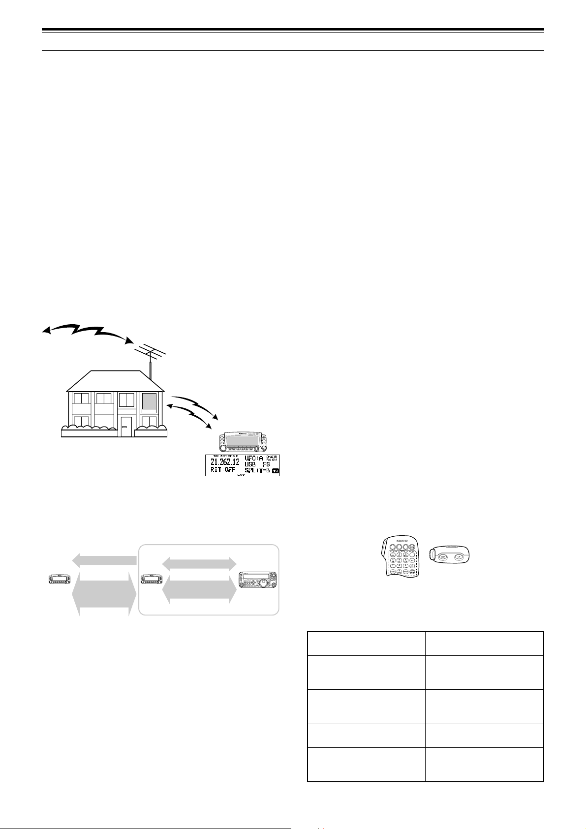
13 OPERATOR CONVENIENCES
FHehthctiwsoT
FFOreviecsnart
ciMsserP ]1[ .
ycneuqerfehtegnahcoT
nolennahcyromemro
reviecsnartFHeht
ciMsserP ]PU[ / ]NWD[ .
nanooiduatimsnartoT
ycneuqerfFH
ciMdlohdnasserP
]TTP[ ehtotnikaepsneht,
.enohporcim
nanooiduaevieceroT
ycneuqerfFH
ciMsserP ]2[ .
dnabFHUehtrotinomoT
rednammoCehtno
ciMehtsserP FP yek
rotinoMehtotdengissa
.noitcnuf
SKY COMMAND II (K-TYPE ONLY)
The Sky Command II allows you to remotely control
the TS-480HX/ SAT transceiver from a separate
location.
If you have more than 2 TH-D7A and/ or TM-D700A
transceivers, you can perform Sky Command II
operation to remotely control the HF/ 50 MHz band of
your TS-480 transceiver.
You will use one transceiver (TH-D7A or TM-D700A)
as a remote control unit, called a “Commander”. The
other VHF/ UHF transceiver (TH-D7A or TM-D700A)
with the TS-480 transceiver is called the
“Transporter”. This TH-D7A or TM-D700A transceier
will function as an interface between the Commander
(a remote control unit) and the HF/ 50 MHz band of
the TS-480 transceiver.
This system allows you, for example, to watch for and
hunt DX while washing your car, or to operate the HF
transceiver while relaxing in your car, living room, or
patio, instead of actually operating inside your shack.
Starting Sky Command II operation:
After you have completed the following setups, you
can start Sky Command II operation. Without
programming these parameters, you cannot perform
Sky Command II operation.
TS-480 + TH-D7A/ TM-D700A (Transporter) Setup:
1 Configure the TH-D7A or TM-D700A as a
“Transporter” and connect all the necessary
cables to the TS-480 transceiver.
2 Select a frequency (HF/ 50 MHz band) on the
TS-480 transceiver.
3 On the TS-480, press [MENU/ F.LOCK], then turn
the MULTI control to access Menu No. 56, then
select the desired communication speed.
4 Select the same communication parameters to
match the TH-D7A or TM-D700A transceiver.
5 Press [MENU/ F.LOCK] to complete.
6 Configure and start the Transporter mode on the
TH-D7A or TM-D700A transceiver.
On the TM-D700A (Commander):
SKY COMMAND II DIAGRAM
VHF freq.
Audio
UHF freq.
Audios
Control commands
tResponse
Commander Transporter
Control commands
Audio
tResponse
1 Select the same VHF and UHF frequencies that
you selected for the Transporter.
2 Access Menu 4–4 to select COMMANDER.
• “PRESS [0] KEY TO START COMMANDER!!”
appears.
3 Press [0] on the DTMF Mic of the TM-D700A to
start the Sky Command II operation.
CONTROL OPERATION
After setting up both the Transporter and the
TM-D700A (Commander) for Sky Command II
operation, press Mic [0] on the Commander. While in
Sky Command II mode, the Mic keys of the
Commander will function as described below.
Each time you press a key, the Commander will
automatically enter Transmission mode and send the
corresponding control command to the Transporter.
PREPARATION
Although you can use either a TM-D700A, a TH-D7A
transceiver as a “Commander” (an external remote
control unit), the following procedure shows how to
set up your TS-480 and TH-D7A or TM-D700A
transceivers as a “Transporter” at a base station and
the TM-D700A transceiver as a “Commander”.
73
Page 82

13 OPERATOR CONVENIENCES
yeKciM noitcnuF
1 FFOrewoP
2 FFO/NOeviecerycneuqerfFH
3 hctiwsedomnoitaludoM
4 FFO/NOTIR
5 FFO/NOTIX
6 raelctesffoTIXrotesffoTIR
7 FFO/NOycneuqerf-tilpS
8 OFVotyromeMmorfrefsnarT
9
0
eveirtersgnittestnerruC
)reviecsnartFHmorf(
hctiwsBOFV/AOFV:edomOFVnI
egnahcoN:edomllaceRyromeMnI
B hctiwsedomllaceRyromeM/OFV
C esaercniycneuqerftesffoTIR/TIX
D esaercedycneuqerftesffoTIR/TIX
1
hctiwszHk1/zH01
:edomWCro,BSU,BSLnI
hctiwszHk01/zHk1:edomMAroMFnI
2
#
NOyrtneycneuqerF:edomOFVnI
rebmunlennahC:edomllaceRyromeMnI
NOyrtne
1
“FS” appears when you select 1 kHz step (LSB/ USB/ CW) or 10 kHz
step (FM/ AM).
2
After pressing Mic [#], press Mic [0] to [9] to enter a frequency or
memory channel number.
When Mic [0] is pressed, the Commander shows the
current settings of the HF transceiver:
w
q
eyr
q HF frequency
w VFO: A, VFO: B,
MR: 00 ~ 99 (memory channel number)
e RIT, XIT
r OFF, –9.99 ~ +9.99
t LSB, USB, CW, FM, or AM
y SPLIT–A: VFO A is used for transmitting.
SPLIT–B: VFO B is used for transmitting.
SPLIT–M: A memory channel is used for transmitting.
u “FS” appears when Mic [
Note:
◆
After pressing
◆
The Transporter will transmit its call sign in Morse code every
10 minutes, using the 144 MHz band.
◆
The APO timer will not operate on the transceiver while the
Transporter is ON.
[MENU]
t
] is pressed.
, you can access only Menu 4–4.
u
TS-480 + TH-D7A/ TM-D700A (Transporter) Setup:
1 Configure the TH-D7A or TM-D700A as a
“Transporter” and connect all the necessary
cables to the TS-480 transceiver.
2 Select a frequency (HF/ 50 MHz band) on the
TS-480 transceiver.
3 On the TS-480, press [MENU/ F.LOCK], then turn
the MULTI control to access Menu No. 56.
4 Select the same communication parameters that
you selected for the TH-D7A or TM-D700A
transceiver.
5 Press [MENU/ F.LOCK] to complete.
6 Start the Transporter mode on the TH-D7A or
TM-D700A transceiver.
TH-D7A (Commander) Setup:
1 Access Menu 4–1 to enter the same callsign that
you entered for the Commander (ex: WD6DJY).
2 Access Menu 4–2 to enter the same callsign that
you entered for the Transporter (ex: WD6DJY-1).
3 Access Menu 4–3 to select the same CTCSS tone
frequency that you selected for the Transporter.
4 Set the same frequencies that you selected for the
“Transporter” for the VHF and UHF bands.
Note:
Refer to Chapter 19, Sky Command II, of the TH-D7A
instruction manual for details on how to enter the callsign and CTCSS
tone frequency.
CONTROL OPERATION
First, switch the TS-480 and TH-D7A or TM-D700A
transceivers (Transporter) ON. Configure the
TH-D7A or TM-D700A to enter the “Transporter”
mode.
Then, access Menu 4–4 on the TH-D7A and select
“COMMANDER”. “PUSH [0] KEY TO START
COMMANDER!!” appears.
Press [0] on the TH-D7A to start Sky Command II
mode.
When in Sky Command II mode, the keys of the
TH-D7A (Commander) will function as described
below. Only [LAMP], [MONI], and the VOL control
functions will not change.
USING TH-D7A AS A COMMANDER
To use a TH-D7A transceiver as a “Commander” (an
external remote control unit), follow the steps below.
Basically, it is the same as using a TM-D700A as a
“Commander” (described on the previous page).
74
Each time you press the desired key, the Commander
will automatically enter Transmission mode and send
the corresponding control command to the
Transporter.
Page 83

FHehthctiwsoT
FFOreviecsnart
nanooiduatimsnartoT
ycneuqerfFH
nanooiduaevieceroT
ycneuqerfFH
dnabFHUehtrotinomoT
rednammoCehtno
yeK noitcnuF
sserP ]REWOP[ .
sserP ]XR[ .
dlohdnasserP ]INOM[ .
13 OPERATOR CONVENIENCES
Note:
◆
On the Transporter, only
function. Pressing any other key will simply cause the
ehtdlohdnasserP TTP
otnikaepsneht,hctiws
.enohporcimeht
Transporter to generate an error beep.
◆
After pressing
◆
The Transporter will transmit its call sign in Morse code every
10 minutes, using the 144 MHz band.
◆
The APO timer will not operate on the transceiver while the
Transporter is ON.
[MENU]
[LAMP], [MONI]
, you can access only Menu 4–4.
, and
[MENU]
will
PU /
B/A
XR
TIR
TIX
RLC
MsV
gninuT
lortnoc
NWD
1
REWOP
1
1
EDOM
1
1
1
1
TILPS
1
egnahc
egnahctesffoTIXrotesffoTIR
FFO/NOrewoP
FFO/NOeviecerycneuqerfFH
hctiwsedomnoitaludoM
FFO/NOTIR
FFO/NOTIX
raelctesffoTIXrotesffoTIR
FFO/NOycneuqerf-tilpS
OFVotyromeMmorfrefsnarT
rebmunlennahcyromemroycneuqerF
hctiwsBOFV/AOFV:edomOFVnI
egnahcoN:edomllaceRyromeMnI
:edomWCro,BSU,BSLnI
TSAF
1
CNYS
hctiwszHk1/zH01
eveirtersgnittestnerruC
)reviecsnartFHmorf(
NOyrtneycneuqerF:edomOFVnI
TNE
lennahC:edomllaceRyromeMnI
NOyrtnerebmun
V/M hctiwsedomllaceRyromeM/OFV
1
After pressing [ENT], you can use these keys as numeric keys to
enter a frequency or memory channel number.
When [0/ SYNC] is pressed, the Commander shows
the current settings of the TS-480 transceiver:
hctiwszHk01/zHk1:edomMAroMFnI
q
e
yr u
q HF frequency
w A (VFO A), B (VFO B),
00 ~ 99 (memory channel number)
e RIT, XIT
r OFF, –9.99 ~ +9.99
t “FS” appears when [FAST] is ON.
y LSB, USB, CW, FM, or AM
u SPLIT–A: VFO A is used for transmitting.
SPLIT–B: VFO B is used for transmitting.
SPLIT–M: A memory channel is used for transmitting.
w
t
75
Page 84

CONNECTING PERIPHERAL EQUIPMENT
COMPUTER
The COM connector allows you to directly connect a computer or dumb terminal by using a straight-wired cable,
having a DB-9 female connector at each end.
No external hardware interface is required between your computer and the transceiver.
To COM port
EXT.SP
DATA
MIC
PADELE
KEY
REMOTE
PANEL
COM
PC
Straight-wired
Cable
To COM connector
(DB-9 female)
COMPATIBLE TRANSCEIVER
When transferring data to or from another TS-480, TS-2000, TS-570, or TS-870S, directly connect the
2 transceivers using the COM connectors.
DB-9 connector wiring
(Cross-wired)
DB-9 female DB-9 female
TS-480HX/ SAT
EXT.SP
DATA
RE
MIC
PADDLE
KEY
MO
PANEL
Cross-wired cable
TS-480/ TS-2000
/ 870S/ 570
TE
C
OM
76
Page 85

14 CONNECTING PERIPHERAL EQUIPMENT
RTTY OPERATION
Use the REMOTE and DATA connectors to interface with your MCP. If your MCP supports RTTY keying output,
connect the output to pin 8 of the REMOTE connector. Connect the demodulation input line of the MCP to
pin 5 of the DATA connector {page 78}. Also, connect the transmission control line of the MCP to pin 3 of the
REMOTE terminal. Select “FSK” or ”FSR” when you operate the RTTY mode.
Note:
Do not share a single power supply between the transceiver and the RTTY equipment. Keep as wide a separation as possible between the
transceiver and the RTTY equipment to reduce noise-pickup by the transceiver.
MCP
Power supply
Mini-DIN (6-pin)
EXT.SP
DATA
MIC
PADELE
KEY
REMOTE
PANEL
COM
MCP
Mini-DIN (8-pin)
Power supply
for the TS-480
HF/ 50 MHz LINEAR AMPLIFIER
Connect an external transmission power amplifier to the REMOTE connector (1 male, 8-pin mini DIN connector
(E57-0405-XX) is supplied). Switch ON the linear amplifier control relay via Menu Nos. 28 (HF) and 29 (50 MHz).
Select “2” or “3” if you use the internal relay to control the linear amplifier status.
The TX/ RX relay response time is 10 ms when you have selected CW Full Break-in and 25 ms when you have
selected CW Semi Break-in.
Note:
◆
The TX/ RX control method differs, depending on external amplifier models. Some amplifiers enter the TX mode when the control terminal is
grounded. For those amplifiers, connect pin 2 of the
connector to the control terminal of the amplifier.
◆
The mini DIN connectors (
connectors. The
REMOTE
DATA
and
REMOTE
connector is an 8-pin mini DIN connector and the
TS-480HX/ SAT
REMOTE
connector to the GND terminal of the amplifier and connect pin 4 of the
connectors) look alike. Confirm the number of pins before plugging into the transceiver
DATA
connector is a 6-pin mini DIN connector.
REMOTE terminal pin assignment (8-pin mini DIN)
Linear Amp.
.oNniP
1OPStuptuorekaepS
niP
emaN
noitcnuF
E
X
T
.S
P
D
A
T
A
R
E
M
O
T
MIC
PADELE KEY
E
PANEL
C
O
M
Use the supplied
mini DIN (8-pin) connector to
interface with the Linear Amp.
Internal relay
for the Linear amplifier.
w
REMOTE connector
(Front view)
u
r
GND
r
w
t
q
2MOCyalerehtfolanimretnommoC
.timsnartotlanimretsihtdnuorG
3SS
To antenna
4EKM
5KRB
(INA ATAD lanimret)rotcennoc
.FFOsnrut
nehw)2nip(MOCotstcennoC
.stimsnartreviecsnarteht
nehw)2nip(MOCotstcennoC
.seviecerreviecsnarteht
6CLA)V7–(reifilpmamorftupniCLA
nehwtuptuosiCDV21+.xorppA
7LR
yi
et
8KTR
.).xamAm01(
stimsnartreviecsnarteht
.tupnigniyek)KSF(YTTR
etanretlaotlanimretsihtdnuorG
.ecapSdnakraM
lateM
–dnuorG
revoc
77
Page 86

14 CONNECTING PERIPHERAL EQUIPMENT
DC
1
DC 2 13.8V
AT
GND
2
ANTENNA TUNER
Use the ANT 1 and AT connectors to connect an AT-300 external antenna tuner. If you connect the external
antenna tuner to the ANT 2 connector, it will not function.
Note:
When the AT-300 is used with the TS-480HX transceiver, the TX output power is automatically reduced to 100 W (AM mode: 25 W).
Also, the AT-300 cannot be used for 50 MHz operation.
1
2
GNDGND
DC
13.8V
ANT 1 connector
MCP AND TNC
Use the DATA connector to connect the AF input/ output lines from a Terminal Node Controller (TNC) for Packet
operation, a Multimode Communications Processor (MCP) for operation on AFSK, Packet, PacTOR, AMTOR,
G-TORTM, PSK31, or FAX, or a Clover interface. Also use the DATA connector to connect SSTV and phone patch
equipment (1 male, 6-pin mini DIN connector (E57-0404-XX) is supplied).
• Connect the TNC or MCP to the DATA connector using a cable equipped with a 6-pin mini DIN plug.
• Connecting the TNC or MCP to a personal computer or dumb terminal requires an RS-232C cable.
• Select LSB or USB mode (it depends on the communication mode) when you operate the MCP/ TNC.
Note:
◆
Do not share a single power supply between the transceiver and the TNC or MCP. Keep as wide a separation as possible between the
transceiver and the computer to reduce noise-pickup by the transceiver.
◆
The mini DIN connectors (
connectors. The
DATA
REMOTE
connector is a 6-pin mini DIN connector and the
and
DATA
connectors) look alike. Confirm the number of pins before plugging into the transceiver
REMOTE
connector is an 8-pin mini DIN connector.
Power Supply
for MCP/ TNC
EXT.SP
DATA
REMOTE
PANEL
COM
DC Power Supply
for the transceiver
MCP/ TNC
Mini DIN male
(6-pin)
MIC
PADELE
KEY
DATA connector pin assignment (6-pin mini DIN)
.oNniP
1INACNT/PCMmorftupnioiduA
2GNAdnuorglangisoiduA
3STD
4CNnoitcennocoN
5ONACNT/PCMroftuptuooiduA
6CQS
lateM
revoc
niP
emaN
DNGdnuorG
noitcnuF
DATA
y
r
t
e
.timsnartotlanimretsihtdnuorG
eht,dednuorgsitinehW
.FFOsnruttupnienohporcim
w
DATA connector
(Front view)
q
sutatshcleuqS
ecnadepmiwoL:nepohcleuqS•
ecnadepmihgiH:esolchcleuqS•
78
Page 87

14 CONNECTING PERIPHERAL EQUIPMENT
DX PACKETCLUSTER TUNE
If you have a TM-D700 transceiver, you can connect the TM-D700 to the TS-480 transceiver to use the DX
PacketCluster Tune function. Connect the 2 transceivers with a cross-wired RS-232C cable as shown below.
Configure the TM-D700 transceiver to the DX PacketCluster node frequency.
TS-480 transceiver
E
X
T.S
P
D
AT
A
RE
M
O
M
IC
PADDLE
KEY
TE
P
AN
EL
C
O
M
TM-D700 transceiver
COM
DATA
GPS
PANEL
MIC
RESET
Cross-wired cable
1 Press [MENU/ F.LOCK] and turn the MULTI control to select Menu No. 56 on the TS-480 transceiver.
2 Press [ ]/ [ ] to select the same communication baud rate configured on the TM-D700 transceiver.
3 Tune to the DX PacketCluster node frequency on the TM-D700 transceiver.
4 Press [F] (1 s), [TNC] on the TM-D700 transceiver.
• “TNC APRS” appears on the TM-D700 transceiver.
5 Press [F] (1 s), [DX] on the TM-D700 transceiver.
cc
6 Select a desired DX station data with [
dd
c]/ [
d] on the TM-D700 transceiver.
cc
dd
7 Press [MHz] on the TM-D700 transceiver to transfer the frequency data to the TS-480 transceiver.
• If the transferred frequency data is available on the TS-480 transceiver, the frequency data will be
overwritten to the current operating frequency. Otherwise, the operating frequency of the TS-480
transceiver remains unchanged.
For more detailed operation on the DX PacketCluster operation of the TM-D700 transceiver, refer to page 6 of the
TM-D700 instruction manual (Specialized Communications).
Note:
The firmware of the TM-D700 transceiver must be version G2.0 or later to use the DX PacketCluster Tune function.
CROSSBAND REPEATER
If you have a TM-D700 transceiver, you can connect the TM-D700 transceiver to the TS-480 transceiver to use
the Crossband repeater function. Connect the 2 transceivers with a mini DIN cable (6-pin) as shown below.
TS-480 transceiver
EX
T.S
P
D
ATA
R
E
M
O
MIC
PADDLE
KEY
TE
PANEL
C
O
M
To DATA connector
After connecting the 2 transceivers with the cable, access Menu No. 57 (DTS polarity) on the TS-480 transceiver
and select “on”. You will further need to adjust the audio input/ output level of the TS-480 transceiver using Menu
Nos. 46 and 47.
TS-480
ty
er
qw
Mini DIN
6-pin male
ANI
q
ANG
w
DTS
e
NC
r
ANO
t
SQC
y
Mini DIN
6-pin male
TM-D700 transceiver
COM
DATA
GPS
PANEL
MIC
RESET
To DATA connector
TM-D700
PKD
q
DE
w
PKS
e
PR9
r
PR1
t
SQC
y
Mini DIN
6-pin male
79
Page 88

14 CONNECTING PERIPHERAL EQUIPMENT
SKY COMMAND II (K-TYPE ONLY)
■ TM-D700A
In order to connect the TS-480 transceiver to the
TM-D700A transceiver, you need to prepare
3 cables by yourself. For the connection between
the COM connectors on the 2 transceivers, you
may use a commercially available RS-232C crosswired cable.
Note:
◆
Switch OFF both the TM-D700 and TS-480 transceiver before
making the connection.
◆
The TM-D700A transceiver automatically transmits its call sign
in Morse code at regular intervals because of legal
requirements; therefore, transmit sidetone must be output
from the TS-480 transceiver.
◆
When the TM-D700A transceiver is too close to the TS-480
transceiver, unwanted feedback may cause malfunction.
◆
Do not share a regulated power supply between the
TM-D700A transceiver and the TS-480 transceiver. Unwanted
feedback may cause malfunction.
TM-D700A
transceiver
COM
connector
3.5 mm (1/8 ")
speaker jack
RJ-45
MIC jack
UP
8 V DC
GND
STBY (MIC)
GND (MIC)
MIC
NC
DWN
TS-480
transceiver
COM
connector
UP
8 V DC
GND
STBY (MIC)
GND (MIC)
MIC
NC
DWN
RJ-45
MIC jack
3.5 mm (1/8 ")
speaker jack
80
Page 89

INSTALLING OPTIONS
You will require a #1 Philips screwdriver to install the
VGS-1. To install the YF-107 IF filter(s) and/ or SO-3
TCXO, you will also need a soldering iron (approx.
30 watts).
REMOVING THE TOP COVER
When installing the optional VGS-1, YF-107 IF filters
or SO-3 TCXO, remove the top cover of the
transceiver:
1 Remove the 8 screws.
OPTION FILTER1
MIC
PADDLE KEY
EX
T.SP
DATA
PANEL
OPTION FILTER2
REMO
TE
CO
M
2 Lift off the top cover.
VGS-1 VOICE GUIDE & STORAGE UNIT
SWITCH OFF THE POWER AND UNPLUG THE DC POWER
CABLE BEFORE BEGINNING INSTALLATION.
1 Remove the top case (8 screws) {above}.
2 Loosen the 4 screws to remove the shield cover.
VGS-1
E
X
T.S
PDA
TA RE
M
M
IC
PADDLE
KEY
OTE
PA
NEL
VGS-1 connector
N
IO
PT
O
XO
C
T
OPTION FILTER1
OPTION FILTE
R2
C
OM
5 Replace the shield cover and tighten the 4 screws.
6 Replace the top case (8 screws).
Note:
After the installation, you can adjust the VGS-1 playback
volume by selecting Menu Nos. 14 and 15.
YF-107C/ CN/ SN IF FILTERS AND SO-3 TCXO
SWITCH OFF THE POWER AND UNPLUG THE DC POWER
CABLE BEFORE BEGINNING INSTALLATION.
Three different types of IF filters (YF-107C,
YF-107CN, and YF-107SN) are available for the
TS-480 transceiver. You can install a maximum of 2
IF filters in the transceiver. Refer to page 90 for the
bandwidth information on each filter. As for the SO-3
option improves the transceiver frequency stability to
±0.5 ppm.
1 Remove the top case (8 screws).
2 Locate the filter and TCXO PCB and loosen the
3 screws.
IF filter/ TCXO PCB
VGS-1 connector
N
O
I
T
P
O
O
X
C
T
OPTION FILTER1
EXT.SP
M
IC
PA
DDLE
DATA
P
A
N
EL
KEY
OPTION FILTER2
REMOTE
COM
3 There are 5 rubber cushions in the VGS-1
package. Use the 2 rubber cushions shown below
and attach them to the VGS-1. The remaining
cushions are not used.
4 Plug the VGS-1 into the VGS-1 connector of the
PC board, pressing down on the top of the VGS-1
until secure.
N
IO
T
P
O
O
X
C
T
OPTION FILTER1
EXT.SP
M
IC
PADDLE
DATA
P
A
N
E
L
KEY
OPTION FILTER2
REMOTE
COM
3 Unlatch the connectors by pressing the connector
tabs upwards.
N
IO
PT
O
XO
TC
O
PTION FILTER1
OPTION FILTER2
N
O
I
T
P
O
O
X
C
T
OPTION FILTER1
EXT.SP
M
IC
PAD
DLE
DATA
P
A
N
E
L
KEY
OPTION FILTER2
REMOTE
COM
4 Insert the IF filter(s) and/ or SO-3 TCXO.
Calibration hole
Secondary IF filter
OPTION FILTER1
OPTION FILTER2
SO-3
Primary IF filter
N
IO
PT
O
XO
TC
81
Page 90

15 INSTALLING OPTIONS
• SO-3: The calibration hole must be on the right
side, looking from the front panel.
• IF filters: Insert a primary IF filter in the OPTION
FILTER1 location, and a secondary IF filter in the
OPTION FILTER2 location. The transceiver
automatically detects what optional IF filter(s) is
installed when it is turned ON.
5 Solder all pins on the reverse side of the PCB.
• SO-3: Cut the 2 wires marked as R103 and R104,
as shown below.
R104
MIC
PADDLE
EXT.SP
PANEL
KEY
R103
X1
PTION
O
XO
TC
OPTION FILTER1
DATA
REMOTE
OPTION FILTER2
COM
6 Replace the PCB in the transceiver and press
both the tabs downwards until secure.
7 Tighten the 3 screws and replace the top cover.
REFERENCE FREQUENCY CALIBRATION
Note:
The transceiver is adjusted at the factory prior to shipping.
Unless necessary, DO NOT perform this adjustment.
1 Set the following on the transceiver:
• Mode: CW
• AF control: Center
• Menu No. 34 (CW RX pitch): 800 Hz
• IF SHIFT control: Center
• RIT function: OFF
• Break-in function (VOX): OFF
2 Remove the top case (8 screws) from the
transceiver.
3 Tune in a standard frequency station such as
WWV or WWVH at, for example, 10.000.00 or
15.000.00 MHz.
• Adjust the Tuning control so that the display
reads the exact frequency of the station.
•You should hear a beat tone of approximately
800 Hz.
• For 800 Hz:
faf = (fdisplay/15.600 x ∆freference) + 800 Hz
where ∆freference is the shift from the 15.6 MHz
reference frequency.
4 Close your CW key. You will hear a transmit
sidetone of approximately 800 Hz.
• This sidetone produces a double beat tone
when it combines with the received signal.
•Adjust the AF control to hear the double beat
clearly.
• For 800 Hz:
fsidetone = 800 Hz ±50 ppm (= 800 ±0.04 Hz)
where ∆freference is the shift from the 15.6 MHz
reference frequency.
5 TS-480 transceiver without SO-3:
Adjust the trimmer (TC1) to minimize the
frequency difference between the received 800 Hz
tone and the 800 Hz sidetone.
TS-480 transceiver with SO-3:
Adjust the trimmer inside the SO-3 using the
supplied plastic adjustment tool (W01-0406-XX).
Minimize the frequency difference between the
received 800 Hz tone and the 800 Hz sidetone.
6 Replace the top cover (8 screws).
82
Page 91

TROUBLESHOOTING
GENERAL INFORMATION
Your transceiver has been factory aligned and tested
to specification before shipment. Under normal
circumstances, the transceiver will operate in
accordance with these operating instructions. All
adjustable trimmers, coils and resistors in the
transceiver were preset at the factory. They should
only be readjusted by a qualified technician who is
familiar with this transceiver and has the necessary
test equipment. Attempting service or alignment
without factory authorization can void the transceiver
warranty.
When operated properly, the transceiver will provide
years of service and enjoyment without requiring
further realignment. The information in this section
gives some general service procedures requiring little
or no test equipment.
SERVICE
If it is ever necessary to return the equipment to your
dealer or service center for repair, pack the
transceiver in its original box and packing material.
Include a full description of the problems
experienced. Include both your telephone number
and fax number (if available) along with your name
and address in case the service technician needs to
call for further explanation while investigating your
problem. Don’t return accessory items unless you
feel they are directly related to the service problem.
You may return your transceiver for service to the
authorized KENWOOD dealer from whom you
purchased it or any authorized KENWOOD service
center. A copy of the service report will be returned
with the transceiver. Please do not send
subassemblies or printed circuit boards. Send the
complete transceiver.
Tag all returned items with your name and call sign
for identification. Please mention the model and
serial number of the transceiver in any
communication regarding the problem.
Note:
◆
Record the date of purchase, serial number and dealer from
whom the transceiver was purchased.
◆
For your own information, retain a written record of any
maintenance performed on the transceiver.
◆
When claiming warranty service, please include a photocopy of
the bill of sale, or other proof-of-purchase showing the date of
sale.
CLEANING
The keys, controls and case of the transceiver are
likely to become soiled after extended use. Remove
the controls from the transceiver and clean them with
a neutral detergent and warm water. Use a neutral
detergent (no strong chemicals) and a damp cloth to
clean the case.
BACKUP BATTERY
This transceiver uses an EEPROM (a.k.a. Flash
ROM) to store memory channel data, menu
configurations and all necessary operation
parameters. So, you never have to worry about
replacing batteries to operate the transceiver.
SERVICE NOTE
If you desire to correspond on a technical or
operational problem, please make your note short,
complete, and to the point. Help us help you by
providing the following:
1 Model and serial number of equipment
2 Question or problem you are having
3 Other equipment in your station pertaining to the
problem
4 Meter readings
5 Other related information (Menu setup, mode,
frequency, key sequence to induce malfunction,
etc.)
DO NOT PACK THE EQUIPMENT IN CRUSHED
NEWSPAPERS FOR SHIPMENT! EXTENSIVE DAMAGE MAY
RESULT DURING ROUGH HANDLING OR SHIPPING.
83
Page 92

16 TROUBLESHOOTING
TROUBLESHOOTING
The problems described in this table are commonly encountered operational malfunctions. These types of
difficulties are usually caused by improper hook-up, accidental incorrect control settings, or operator error due to
incomplete programming. These problems are usually not caused by circuit failure. Please review this table, and
the appropriate section(s) of this instruction manual, before assuming your transceiver is defective.
Note:
Placing a powered portable transceiver near this transceiver may cause noise in the transceiver.
gnisserp ][ gnihtoN.
.draeh
.yalpsid
.timsnart
melborP esuaCelbaborP noitcAevitcerroC
tonlliwreviecsnartehT
1
retfapurewop
dnaylppusrewop
noitcnuftonseod
ehtnoraeppastigid
eht,reviecsnart
yekgnisserpretfa
.launamsihtni
.degnahceb
2
CDV8.31agnitcennoc
3
,yalpsidehtnosraeppa
siesionreviecerondna
4
ehtNOgnihctiwsretfA
1
reviecsnarteht,rewop
2
,elpmaxeroF.yllamron
tcerrocnirostigidon
ehtNOgnihctiwsretfA
1
otsesuferreviecsnart
2
seodreviecsnartehT
1
yltcerrocdnopserton
2
gninrutrosnoitanibmoc
snoitcurtsnirepslortnoc
3
tonnacycneuqerfehT
.yleruces
CD ± .)CDV8.51ot7.11(%51
.NO
elbacrewopytluaF
.denoitcnuflam
.yticapactnerruc
.ylesicerpdewollof
.FFOsiylppusrewopCD
.neposiesufelbacrewoP
sahrossecorporcimehT
CDehtfognitartnerrucehT
.wolootsiylppusrewop
gniebtoneraserudecorP
stidnarossecorporcimehT
.gnitteserdeenyromem
ronoitcnufkcoLycneuqerFehT
.NOsinoitcnufllAkcoL
1
2
detcennoctonsielbacrewopehT
3
4
V8.31edistuosiegatlovtupniehT
1
2
1
seilppusrewopCDemasowT
2
CDaro)hcaeeromroA5.02(
eromA14sahtahtylppusrewop
1
sinoitcnufkcoLycneuqerFehT
2
3
sserP )s1(]KCOL.F/UNEM[ hctiwsot
sserP )s1(]KCOL.F/UNEM[ ehtnrutot
egaP
.feR
.ylppusrewopCDehtNOhctiwS
mrifnoC.elbacrewopehttcepsnI
.tcerroceraseitiralop
)–(evitagen:kcalB;)+(evitisop:deR
CDehtotsnoitcennocehtmrifnoC
.eruceseraylppusrewop
.esufnwolbehtfoesuacehtrofkooL
ynagnitcerrocdnagnitcepsniretfA
ehtfoesufwenallatsni,smelborp
.gnitardeificeps
.yrettabV61
ROSSECORPORCIM“weiveR
tahwgnidnatsrednuretfA.”TESER
sahtahtylppusrewopCDehtesU
.gnitartnerruceromroA5.02
ehtotseilppusrewopCD2tcennoC
egatlovehT.reviecsnartXH084-ST
rewopCD2neewtebecnereffid
otV0.1nihtiwebtsumseilppus
tnerrucrehgihroA5.02asahylppus
sahtahtylppusrewopCDafI.gnitar
emasowt,yticapactnerruceromA14
.desuebtsumselbacCDfoepyt
SNOITNEVNOCGNITIRW“weiveR
.”DEWOLLOF
.FFOnoitcnufeht
ROSSECORPORCIM“weiveR
tahwgnidnatsrednuretfA.”TESER
”“ehT.FFOnoitcnufkcoLycneuqerF
.sraeppasidnoci
81
3,2
3,2
5
ot21aesuroegatlovtupniehttcerroC
3,2
88
fI.teseRlaitraPaod,tsoleblliwatad
.teseRlluFaod,sniamermelborpeht
3
3
rewopCDhcaemrifnoc,oslA.timsnart
ii
36
88
fI.teseRlaitraPaod,tsoleblliwatad
.teseRlluFaod,sniamermelborpeht
36
84
siytilauqoiduaBSS
.tnesbaera
1
rohgiheht;roopyrev
seicneuqerfoiduawol
2
.tes
3
4
siedomnoitarepognorwehT
.reviecerehtrofdetceles
.NOsi2ro1lecnaCtaeB
1
yltcerrocnisiretlifPSDFAehT
2
.NOsi2ro1noitcudeResioN
3
4
sserP ]RAN/LIF[ ehtnrutneht ITLUM
sserP ]RN[ snrutnoitcnufRNehtlitnu
.FFO
sserP ]T.WC/CB[ noitcnufCBehtlitnu
.FFOsnrut
.edomehtrofBSLroBSUtceleS
.htdiwretlifPSDehttsujdaotlortnoc
91
64
74
74
Page 93

16 TROUBLESHOOTING
melborP esuaCelbaborP noitcAevitcerroC
eraslangisoN
.roop
eraslangisoN
siretem-S;roop
yllatotera
.elbigilletninu
yllufsseccus
roTAS084-ST(
htiwXH084-ST
.)003-TA
1
ehT LQS .esiwkcolcyllufsilortnoc
eviecerrodeviecer
2
smeesytivitisnes
3
ciM ]TTP[ .desserpsi
4
.tesyltcerrocni
5
6
eviecerrodeviecer
smeesytivitisnes
.elacsllufgnidaer
slangisdevieceR
.detceles
lliwnacSyromeM
1
ehT LQS testonsawlortnoc
.gninnacstratston
2
3
lliwnacSyromeM
ehtfoenonacston
eht;slennahcderots
silennahcderised
.tuodekcolTON
lliwnacSmargorP
.gninnacstratston
hsiniftonseodTA
.yltcerroc
.dekcolnu
.demmargorp
.lacitnedi
.dehctamtonsawannetna
.NOsinoitcnufrotaunettAehT
sawhtdiwdnabretlifFIehT
rotcennocannetnagnorwehT
.detcelessaw)2TNAro1TNA(
.FFOsireifilpmaerpehT
.woloottessawniagFRehTsserP )s1(]G.FR/5/CIM[ ehtnrutdna
sawedomnoitaludomgnorwehT
eraseicneuqerfdnednatratsehT
hsinifyllufsseccustonseodgninuT
1
2
3
4
5
6
1
erewslennahcyromem2nahtsseL
2
erewslennahcyromem2nahtsseL
3
lennahceht,detcelesnacSpuorGhtiW
.puorgtnereffidanisinacsottnawuoy
dnaelbaclaixaocehtfoecnadepmiehT
ehthguohtlasnoitidnocnognidneped
.1:3nahtrellamssetacidniretemRWS
ehtnruT LQS lortnoc.esiwkcolcretnuoc
sserP ]2/1TNA/ERP/TTA[ ”TTA“litnu
.raeppasid”ERP“dna
ciMesaeleR ]TTP[ .
GNIGNAHC“,”SRETLIFPSD“weiveR
.ylgnidroccaslortnoceht
sserP )s1(]2/1TNA/ERP/TTA[ ot
.rotcennocannetnarehtoehttceles
sserP ]2/1TNA/ERP/TTA[ hctiwsot
.NOnoitcnufeht
ITLUM ehtesaercniotesiwkcolclortnoc
.niagFR
sserP ]EDOM[ ro )s1(]EDOM[ tcelesot
.edomnoitaludomtcerroceht
ehttsujdA LQS etanimiletsujotlortnoc
.esiondnuorgkcab
.slennahcyromem2tsaeltakcolnU
yromem2tsaeltaniataderotS
.slennahc
sniatnoctahtpuorGyromeMehttceleS
.nacsottnawuoylennahcyromemeht
.seicneuqerfdnednatratstnereffiderotS35
ehtrewolotmetsysannetnaehttsujdA
.RWS
egaP
.feR
91
16
02
,54
tesdna”HTDIWDNABRETLIFFIEHT
64
06
94
81
91
91
45
05
95
06
dessapyb
uoyhguohtneve
ciMsserp ]TTP[ ro
.stcatnoconni
sirenutlanretniehT
.hgih
retfayletaidemmi
.detratssigninut
timsnarttonnacuoY
1
.rotcennoc
tlusersnoissimsnart
2
3
.edomeciova
4
.detcelesylreporpni
5
ootsimetsysannetnaehtfoRWSehT
.RWS
tonsawgulpenohporcimehT
CIMehtotniyletelpmocdetresni
rotcennocannetnagnorwehT
.detcelessaw)2TNAro1TNA(
1
.NOsinoitcnuftibihnItimsnarTehT
2
fodaetsnidetcelessawKSFroWC
3
sawhtdiwdnabretlifXTPSDehT
4
5
sserP ]EDOM[ .edomeciovatcelesot
sserP )s1(]2/1TNA/ERP/TTA[ ot
ehtrewolotmetsysannetnaehttsujdA
CIMehterusne,rewopehtFFOnruT
.ylmrifrotcennocehtnigulpneht
.FFOot55.oNuneMegnahC
.02.oNuneMnisgnittesehttsujdA
.rotcennocannetnarehtoehttceles
06
6
,tinistcejbongierofonsahrotcennoc
83
91
83
06
85
Page 94

16 TROUBLESHOOTING
melborP esuaCelbaborP noitcAevitcerroC
otgnitpmettA
”OLLEH“eht
gniebedom
.derotser
noissimsnartwol
.rewop
tonseodXOV
.etarepo
.etarepo
rewoptuptuo
noitarepolatigiD
tastpmettA
ehtgnillortnoc
evahretupmoc
.deliaf
1
nistlusertimsnart
2
gniraeppaegassem
noitpecerehtdna
3
CD ± .)CDV8.51ot7.11(%51
4
sahreviecsnartehT
1
2
raeniLzHM05/FH
1
tonseodreifilpma
2
s’reviecsnartehT
1
aretfasesaerced
2
.emitgnitarepotrohs
sseccatonnacuoY
1
.sretaeperesudna
2
1
onrowefnistluser
stcatnocrostcennoc
.snoitatsrehtohtiw
2
3
4
5
1
ehthtiwreviecsnart
2
.yltcerroc
.dehctam
.hguonetonsiylppus
ehT ETOMER signiriwrotcennoc
.ytluafrognorw
.nwodreviecsnart
.gnorwsiycneuqerf
.gnorweraPCM/CNT
.sretemarapreviecsnart
detcennoctonsiannetnaehT
ylreporptonerareviecsnart
.RWShgihgnisuacera
.woloottessiniagXOVehT.niagXOVehtesaercnI63
.tsudhtiwdetsegnocneebevah
ehtloocotwolfriahguone
.sseccaotenotzH0571
noitpecerro/dnanoissimsnarT
ehtneewtebsnoitcennoclacisyhP
.desugnieberaseicneuqerf
ehtrolangisdettimsnartruoY
.tesyltcerrocnisawPCM/CNT
.TAS/XH084-STehtotCPeht
ehthctamtonodmargorplanimret
1
.yrassecensatcerroC
dnaannetnaehtfosecnadepmiehT
2
.metsys
V8.31edistuosiegatlovtupniehT
3
.yrettabV61
rewopCDehtfognitartnerrucehT
4
.timsnart
.woloottessiniagenohporcimehT
1
.niagenohporcimeht
snoitcennocmetsysannetnarooP
2
.RWSwolagnitroper
.FFOsilortnocreifilpmaraenilehT
1
2
)s(nafgniloocehtrofsretlifriaehT
1
edivorptonnac)s(nafgniloocehT
2
roenotbusaeriuqersretaeperynaM
1
2
1
PCM/CNTdna,retupmoc,reviecsnart
ehtnisgnitteserawtfosro,tcerrocnisi
noitpecerdnanoissimsnarttnereffiD
2
reviecsnartehtneewtebslevelehT
3
.tcerrocnieraPCM/CNTehtdna
4
.kaewootsilangiseviecergnimocni
ruoyniretemarapemityaledXTehT
5
stcennoctahtelbacehthtiwmelborP
1
ruoynitessretemarapnoitacinummoC
2
ehttcepsnI ETOMER gniriwrotcennoc
atcatnoC DOOWNEK dezirohtua
.delooctinuehtpeek
.enotbusfoepyt
.secnerefer
.PCM/CNTruoy
.sm003nahterom
.snoitcennoc
.65.oNuneMkcehC
.noitcennocannetnaehtkcehC
annetnaehtfoRWSehtecudeR
asahtahtylppusrewopCDaesU
taA5.02nahteromfognitartnerruc
,XH084-STehtrofsA.CDV8.31
otderiuqereraseilppusrewopCD2
esaercni,edomMAroBSSninehW
.snoitcennocannetnaehtkcehC
sirenutannetnaehttahtmrifnoC
ro)FH(82.oNuneMteS
.3ro,2,1ot)zHM05(92
.yrassecensatitcerrocdna
.sretlifehtnaelcotretnececivres
ottinuXR/XTehthguorhtwolfylisae
dnaycneuqerftcerrocehttcelesdna
s’retaeperehtnotimsnarttsumuoY
ehtnoeviecerdnaycneuqerftupni
otrefeR.ycneuqerftuptuos’retaeper
.”NOITAREPORETAEPERMF“
sihtgnisusnoitcennocllakcehc-eR
dna,launamPCM/CNTruoy,launam
salaunamerawdrahretupmocruoy
uoytahtmrifnoC.FFOdehctiwsera
.ycneuqerftilpsgnitarepoTONera
uneMgnisuslevelXRdnaXTtsujdA
noslortnocleveldna,74dna64.oN
roannetnaruoyetacoler/tneiroeR
.niagannetnaruoyesaercni
otemityaledXTPCM/CNTehtteS
elbacdnaelbacehtkcehC
ehtnisretemarapemasehtesU
ot21aesuroegatlovtupniehttcerroC
nacriatahtosreviecsnartehtetacoleR
snoitcnufTIXdnaTIRehttahtmrifnoC
.reviecsnartehtdnamargorplanimret
egaP
.feR
4,2
4,2
2
3
,72
82
06
36
77
98
98
”NOITAREPORETAEPERMF“weiveR
13
13
,77
87
,53
73
,77
87
4,2
–
67
76
86
Page 95

16 TROUBLESHOOTING
melborP esuaCelbaborP noitcAevitcerroC
sraeppa”IH–PMET“
ni”KCEHC“dna
.sdnuosedocesroM
dna”RORREAP“
esroMni”KCEHC“
neht,sdnuosedoc
noissimsnarteht
XH084-ST(spots
.)ylno
sraeppa”YLNOXR“
ni”KCEHC“dna
sdnuosedocesroM
.)ylnoXH084-ST(
”RORRECD“
dnasraeppa
esroMni”KCEHC“
.sdnuosedoc
noissimsnarT
.spotsylneddus
.tiucric
1
2
.hgihootsi
1
2
3
.desu
.erutarepmethgih
.rotcennoc2-CDeht
.CDV0.1
.hgihootsi)s(ylppus
detcetedreviecsnartehtnirosnesA
atcatnoC.elihwarofnwodlooc
DOOWNEK otretnececivresdezirohtua
.sretlifrialanretniehtnaelc
detcetedreviecsnartehtnirosnesA
reifilpmarewopXTehtnisnoitcnuflam
atcatnoc,stsisrep DOOWNEK dezirohtua
.sriaperrofretnececivres
otdetcennoctonsielbacCDehT
1
ehtneewtebecnereffidegatlovehT
2
ehtnosrotcennoc2-CDdna1-CD
.CDV0.1nahtretaergsireviecsnart
.CD
)s(ylppusrewopCDehtfoegatlovehT
.CDV8.31
neewtebecnereffidegatlovehT
rewopCDehtfoegatlovehT
1
ehtnosrotcennoc2-CDdna1-CD
nahtretaergsemocebreviecsnart
.CD
2
.CDV8.31
eraselbacCDfoepyttnereffidowT
3
.selbacCDfoepytemasesU
reviecsnartehtteldnagnittimsnartpotS
,elihwarofnwodloocreviecsnartehtteL
melborpehtfI.teserlluFehtmrofrepneht
rewopCDeht)tcennocro(ylppA
.rotcennoc2-CDehtotecruos
foegatlovCDtuptuoehttahtmrifnoC
.CDV8.31siseilppusrewopCDhtob
V0.1nihtiwebtsumecnereffidehT
otegatlovylppusrewopCDehttsujdA
foegatlovCDtuptuoehttahtmrifnoC
.CDV8.31siseilppusrewopCDhtob
V0.1nihtiwebtsumecnereffidehT
otegatlovylppusrewopCDehttsujdA
egaP
.feR
–
88
3,2
3,2
3
3,2
3
3,2
”RRESGV“
.sraeppa
tonnacegassemA
deyalp/dedrocereb
onrokcab
nactnemecnuonna
.draeheb
reviecsnartehT
smeesrewoptuptuo
BSSniwolebot
.edom
rorrenoitacinummocasierehT
.edomBSSniklatdnaetarepo
.)rewopepolevnekaep(PEP
.1-SGVehtniderruccororrelanretninA si1-SGVforotcennocehtmrifnoC
.reviecsnartehtotdetcennocyleruces
melborpehtfI.teserlluFehtmrofreP
atcatnoc,stsisrep DOOWNEK dezirohtua
.sriaperrofretnececivres
si1-SGVforotcennocehtmrifnoC
.1-SGVdnareviecsnartehtneewteb
atcatnoc,stsisrep DOOWNEK dezirohtua
.sriaperrofretnececivres
sretemrewopFRlanretxeehtfotsoM
,oS.rewopFRegarevaehterusaem
uoynehwwolsignidaerretemeht
.leveltuptuoFRsihtsaemas
sah084-STehtnidesuretemDCLehT
tonsititubemitesnopsertsafylevitaler
etaruccaehterusaemothguonetsaf
.reviecsnartehtotdetcennocyleruces
melborpehtfI.teserlluFehtmrofreP
ot)zHk1(enotelgnissuounitnocaylppA
erusaemottupnioiduaenohporcimeht
,38
88
,38
88
–
ehteblliwPEPehT.rewoptuptuoFReht
87
Page 96

16 TROUBLESHOOTING
MICROPROCESSOR RESET
If your transceiver seems to be malfunctioning,
resetting the microprocessor default settings may
resolve the problem. There are 2 levels of resetting
the microprocessor of the TS-480 transceiver: Partial
Reset and Full Reset.
INITIAL SETTINGS
For each VFO, the factory defaults for the operating
frequency and mode are as follows:
• VFO A: 14.000.00 MHz/ USB
• VFO B: 14.000.00 MHz/ USB
The Memory channels and Quick Memory channels
have no data stored.
PARTIAL RESET
Perform a Partial Reset if a key or control does not
function according to the instructions in this manual.
The following data is NOT erased by performing a
Partial Reset.
• Memory channel data
• Menu settings
• Antenna tuner preset data
• ANT 1/ ANT 2 selection data
• Frequency and mode data for the Auto Mode
function
•Various adjustment setting values
Reset the transceiver by pressing [A/B / M/V]+[ ].
•A confirmation message appears when performing
the Partial Reset. Press [A/B / M/V] to proceed.
Otherwise, press any other key to cancel the
Partial Reset and return to normal operation.
• The VFOs reset to the factory default values.
DEMONSTRATION MODE
The transceiver can be configured to enter the
demonstration mode for display purposes. To enter
the demonstration mode:
1 Switch the transceiver OFF.
2 Press [MENU/ F.LOCK]+[ ] to switch the
transceiver ON.
• The display brightness changes, the LED turns
ON/ OFF, and alpha-numeric segments turn
ON/ OFF automatically.
• If you operate the transceiver while in the
demonstration mode, the demonstration is
temporarily paused. But, if no operation is
performed for more than 10 seconds, the
demonstration starts again.
3 To exit the demonstration mode, first turn the
transceiver OFF, then press
[MENU/ F.LOCK]+[ ] to turn the transceiver ON.
Note:
You cannot exit the demonstration mode by simply switching
the transceiver OFF. You must switch the transceiver OFF then press
[MENU/ F.LOCK]+[ ]
demonstration mode.
to turn the transceiver ON in order to exit the
FULL RESET
Perform a Full Reset if you want to erase all the data
in all the memory channels. In addition, this function
resets all the settings that you customized, to the
factory defaults (i.e.- menu settings, antenna tuner
preset data, etc.).
Reset the transceiver by pressing
[A=B/ SPLIT]+[ ].
A confirmation message appears when performing
Full Reset. Press [A=B/ SPLIT] to proceed.
Otherwise, press any other key to cancel the Full
Reset and return to normal operation.
When you perform the Full Reset:
• All frequencies, modes, memory data, adjustment
values, and AT preset data are set to the factory
default values.
88
Page 97

OPERATION NOTICES
The transceiver has been designed and engineered
to avoid possible hardware glitches. However, you
may notice the following symptoms when you operate
the transceiver. These symptoms are not
malfunctions.
DC POWER SUPPLY
As stated in the SPECIFICATIONS {page 91}, this
transceiver requires a supplied DC voltage source of
13.8 V ±15%. If you find that the transceiver cannot
be switched ON, or that it shuts OFF automatically,
the DC voltage may be outside the specified range.
In such a case, remove the DC cable from the
transceiver immediately and confirm that the supplied
voltage is within the specified range.
FAN NOISES
When the TX/ RX unit is installed in a non-ventilated
area, the cooling fan(s) may increase in speed and
emit a high level of noise for a long time. This is
because the TX/ RX unit cannot be cooled down with
the regular fan speed. In this case, relocate the TX/
RX unit so that air can easily flow through the TX/ RX
unit to keep the unit cooled.
16 TROUBLESHOOTING
INTERNAL BEATS
On some spots of the receiver frequencies, the
S-meter moves or you cannot receive any signals.
This is inevitable when you use superheterodyne
receivers. You may notice the signals on the
following spots of the frequency.
15.600.00 MHz, 31.200.00 MHz, 46.800.00 MHz
AGC
When you turn the AGC function OFF {page 35}, the
receiving audio signals can be distorted. In this case,
decrease the RF gain, turn the pre-amplifier OFF, or
turn the attenuator ON. In general, the RF gain must
be greatly reduced when the AGC is turned OFF.
60 m BAND OPERATION (K-TYPE/ U. S. A. ONLY)
Effective from July 3, 2003, FCC Report and Order
(R&O) in ET Docket 02-98 granted US amateurs
secondary access to five discrete channels in the
vicinity of 5 MHz. General, Advanced, and Amateur
Extra licensees may use the following five channels
on a secondary basis with a maximum effective
radiated power of 50 W PEP relative to a half wave
dipole. Only upper sideband suppressed carrier voice
transmissions may be used. The frequencies are
5330.5, 5346.5, 5366.5, 5371.5 and 5403.5 kHz. The
occupied bandwidth is limited to 2.8 kHz centered on
5332, 5348, 5368, 5373, and 5405 kHz respectively.
The TS-480 transceiver stops at this new 60 m band
as you scroll up or down amateur radio frequency
bands. For more information, contact ARRL or
search their Web site (http://www.arrl.org) with a key
word, “60 meter”.
89
Page 98

OPTIONAL ACCESSORIES
ARCP-480/ ARHP-10
Remote control software
Refer to page 68 for details.
MC-43S
Microphone
MJ-88 is required. MJ-88 is required.
PG-20
DC cable (7 m/ 23 ft)
HS-5
Delux Headphones
MC-47
Multi-function Microphone
MJ-88 is required.
PG-4Z
Extension cable kit
(4 m/ 13 ft)
HS-6
Small Headphones
MC-60A
Desk-top Microphone
PS-53
Regulated DC Power
Supply (22.5 A)
LF-30A
Low-pass Filter
TS-480SAT only
MJ-88
Plug adaptor
(8-pin metal to RJ45)
SO-3
TCXO unit
SP-50B
Mobile Speaker
YF-107C
500 Hz IF filter
SP-23
External Speaker
YF-107SN
1.8 kHz IF filter
VGS-1
Voice Guide and Storage
unit
YF-107CN
270 Hz IF filter
90
Page 99

SPECIFICATIONS
lareneG
edoM
slennahcyromemforebmuN )slennahcyromemkciuQ(01+001
ecnadepmiannetnAdnabm6~m061
egatloVylppuSV8.31CD ± %51
dohtemgnidnuorGdnuorgevitageN
tnerruC
egnarerutarepmetelbasU02– ° 06~C ° 4–(C ° 041~F ° )F
ytilibatsycneuqerF
3-OStuohtiw
ytilibatsycneuqerF
3-OShtiw
snoisnemiD
DxHxW(
01– ° 05~C °CnihtiW ± mpp5
02– ° 06~C °CnihtiW ± mpp01
01– ° 05~C °CnihtiW ± mpp5.0
02– ° 06~C °CnihtiW ± mpp0.1
tinuXR/XT2x"7/mm872x5.96x971
)dedulcnisnoitcejorP
).xam(timsnarTsselroA5.02sselroA0.14
)langison(evieceRsselroA5.1
lenaplortnoCetomeR7/mm86x87x381
05 Ω annetnani-tliubhtiw(
)KSF(B1F
TAS084-STXH084-ST
051~7.61renut Ω )
61/3
05 Ω
4/3
/)MF(E3F/)MA(E3A/)WC(A1A/)BSU,BSL(E3J
01x"
61/51
"
2x"3x"
8/5
"
thgieW
egnarycneuqerF
tinuXR/XTsbl7/gk2.3.xorppA
lenaplortnoCetomeRzo2bl1/gk5.0.xorppA
rettimsnarT
dnabm061)epyt-E(zHM0.2~18.1)epyt-K(zHM0.2~8.1
dnabm08)epyt-E(zHM8.3~5.3)epyt-K(zHM0.4~5.3
dnabm06)epyt-K(zHM54.5~52.5
dnabm04)epyt-E(zHM1.7~0.7)epyt-K(zHM3.7~0.7
dnabm03zHM51.01~1.01
dnabm02zHM53.41~0.41
dnabm71zHM861.81~860.81
dnabm51zHM54.12~0.12
dnabm21zHM99.42~98.42
dnabm01zHM7.92~0.82
dnabm6)epyt-E(zHM0.25~0.05)epyt-K(zHM0.45~0.05
MF/KSF/WC/BSS
TAS084-STXH084-ST
)dnabm01~m061(W002
.xaM)dnabm6~m061(W001
)dnabm6(W001
rewoptuptuO
MA
BSSdecnalaB
noitaludoM
MFesahP
MAlevelwoL
.niM)dnabm6~m061(W5)dnabm6~m061(W5
)dnabm01~m061(W05
.xaM)dnabm6~m061(W52
)dnabm6(W52
.niM)dnabm6~m061(W5)dnabm6~m061(W5
91
Page 100

20 SPECIFICATIONS
rettimsnarT
snoissimesuoirupS
)BSS(noisserppusreirraCeromroBd04
noisserppusdnabedisdetnawnU
)zHk0.1ycneuqerfnoitaludom(
ycneuqerfmumixaM
)MF(noitaived
egnarycneuqerftfihsTIX ± zHk99.9
ecnadepmienohporciM006 Ω
revieceR
epyttiucriC
egnarycneuqerF zHM999.999.95~50.0
)FI(ycneuqerFetaidemretnI
ytivitisneS
ediW ± sselrozHk5
MA
MF
dnabm01~m061sselroBd05–
dnabm6sselroBd06–
worraN ± sselrozHk5.2
KSF/WC/BSS
)Bd01N/S(
)Bd01N/S(
)DANISBd21(
TAS084-STXH084-ST
eromroBd04
TAS084-STXH084-ST
enydoretehrepus.vnocelbuoD:KSF/MA/WC/BSS
enydoretehrepusnoisrevnocelpirT:MF
zHM590.37:FIts1
zHM596.01:FIdn2
zHk554:)ylnoMF(FIdr3
4:zHM507.1~5.0 µ sselroV
2.0:zHM5.42~507.1 µ sselroV
31.0:zHM0.03~5.42 µ sselroV
31.0:zHM0.45~0.05 µ sselroV
6.13:zHM507.1~5.0 µ sselroV
0.2:zHM5.42~507.1 µ sselroV
3.1:zHM0.03~5.42 µ sselroV
3.1:zHM0.45~0.05 µ sselroV
22.0:zHM0.03~0.82 µ sselroV
22.0:zHM0.45~0.05 µ sselroV
BSSsselrozHk4.4:Bd06–,eromrozHk4.2:Bd6–
ytivitceleS
noitcejeregamIeromroBd07
noitcejerFIts1eromroBd07
egnarycneuqerftfihsTIR ± zHk99.9
ytivitisneshcleuqS
8(tuptuooiduA Ω )noitrotsid%01,eromroW0.2
MAsselrozHk0.04:Bd06–,eromrozHk0.5:Bd6–
MFsselrozHk0.52:Bd05–,eromrozHk0.21:Bd6–
)zHk1ta(noitaunettalecnaCtaeBeromroBd04
MF
)PS.TXE(ecnadepmituptuooiduA8Ω
0.81:zHM507.1~5.0 µ sselroV
MA/KSF/WC/BSS
8.1:zHM0.03~8.1 µ sselroV
1.1:zHM0.45~0.05 µ sselroV
2.0:zHM0.03~0.82 µ sselroV
2.0:zHM0.45~0.05 µ sselroV
92
 Loading...