


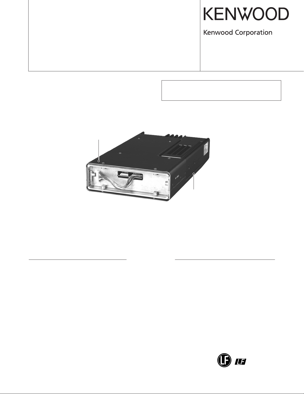
UHF P25 TRANSCEIVER
TK-5810H(B
SERVICE MANUAL
Cabinet (Upper)
(A01-2163-21)
)
2007-6 PRINTED IN JAPAN
©
B51-8797-00 (S
This service manual is issued as TK-5810H(B). For items
not provided in this service manual, please refer to the
TK-5810(B): B51-8780-00 service manual.
) 500
CONTENTS
GENERAL .............................................................. 2
SYSTEM SET-UP .................................................. 4
DISASSEMBLY FOR REPAIR ............................... 5
CIRCUIT DESCRIPTION ........................................ 7
COMPONENTS DESCRIPTION ............................ 8
TERMINAL FUNCTION ......................................... 9
PARTS LIST ......................................................... 10
EXPLODED VIEW ................................................ 18
PACKING ............................................................. 19
ADJUSTMENT .................................................... 20
Cabinet (Lower)
(A01-2164-31)
PC BOARD
FINAL UNIT (X45-3800-XX) ........................... 22
TX-RX UNIT (X57-7270-XX) ........................... 26
SCHEMATIC DIAGRAM ...................................... 30
INTERCONNECTION DIAGRAM ........................ 36
BLOCK DIAGRAM ............................................... 38
LEVEL DIAGRAM ................................................ 40
SPECIFICATIONS ............................. BACK COVER
This product uses Lead Free solder.

TK-5810H(B
)
GENERAL
Document Copyrights
Copyright 2007 by Kenwood Corporation. All rights
reserved.
No part of this manual may be reproduced, translated,
distributed, or transmitted in any form or by any means,
electronic, mechanical, photocopying, recording, or otherwise, for any purpose without the prior written permission
of Kenwood.
Disclaimer
While every precaution has been taken in the preparation
of this manual, Kenwood assumes no responsibility for
errors or omissions. Neither is any liability assumed for damages resulting from the use of the information contained
herein. Kenwood reserves the right to make changes to any
products herein at any time for improvement purposes.
Firmware Copyrights
The title to and ownership of copyrights for firmware
embedded in Kenwood product memories are reserved for
Kenwood Corporation. Any modifying, reverse engineering,
copy, reproducing or disclosing on an Internet website of
the firmware is strictly prohibited without prior written
consent of Kenwood Corporation. Furthermore, any
reselling, assigning or transferring of the firmware is also
strictly prohibited without embedding the firmware in
Kenwood product memories.
P25 Transceivers:
The IMBE(TM) voice coding technology is embedded in
the firmware under the license of Digital Voice Systems, Inc.
INTRODUCTION
SCOPE OF THIS MANUAL
This manual is intended for use by experienced technicians familiar with similar types of commercial grade communications equipment. It contains all required service information for the equipment and is current as of this publication date. Changes which may occur after publication are
covered by either Service Bulletins or Manual Revisions,
which are issued as required.
ORDERING REPLACEMENT PARTS
When ordering replacement parts or equipment information, the full part identification number should be included.
This applies to all parts : components, kits, and chassis. If
the part number is not known, include the chassis or kit
number of which it is a part and a sufficient description of
the required component, for proper identification.
PERSONAL SAFETY
The following precautions are recommended for personal
safety :
•DONOT transmit if someone is within two feet (0.6
meter) of the antenna.
•DONOT transmit until all RF connectors are secure and
any open connectors are properly terminated.
• SHUT OFF this equipment when near electrical blasting
caps or while in an explosive atmosphere.
• All equipment should be properly grounded before
power-up for safe operation.
• This equipment should be serviced by only qualified
technicians.
PRE-INSTALLATION CONSIDERATIONS
1. UNPACKING
Unpack the radio from its shipping container and check
for accessory items. If any item is missing, please contact
KENWOOD immediately.
2. LICENSING REQUIREMENTS
Federal regulations require a station license for each
radio installation (mobile or base) be obtained by the
equipment owner. The licensee is responsible for ensuring
transmitter power, frequency, and deviation are within the
limits permitted by the station license.
Transmitter adjustments may be performed only by a
licensed technician holding an FCC first, second or general
class commercial radiotelephone operator’s license. There
is no license required to install or operate the radio.
3. PRE-INSTALLATION CHECKOUT
3-1. Introduction
Each radio is adjusted and tested before shipment.
However, it is recommended that receiver and transmitter
operation be checked for proper operation before
installation.
3-2. Testing
The radio should be tested complete with all cabling and
accessories as they will be connected in the final installation. Transmitter frequency, deviation, and power output
should be checked, as should receiver sensitivity, squelch
operation, and audio output. Signaling equipment operation
should be verified.
4. PLANNING THE INSTALLATION
4-1. General
Inspect the vehicle and determine how and where the
radio antenna and accessories will be mounted.
Plan cable runs for protection against pinching or crush-
ing wiring, and radio installation to prevent overheating.
4-2. Antenna
The favored location for an antenna is in the center of a
large, flat conductive area, usually at the roof center. The
trunk lid is preferred, bond the trunk lid and vehicle chassis
using ground straps to ensure the lid is at chassis ground.
2

GENERAL
4-3. Radio
The universal mount bracket allows the radio to be
mounted in a variety of ways. Be sure the mounting surface
is adequate to support the radio’s weight. Allow sufficient
space around the radio for air cooling. Position the radio
close enough to the vehicle operator to permit easy access
to the controls when driving.
4-4. DC Power and wiring
1. This radio may be installed in negative ground electrical
systems only. Reverse polarity will cause the cable fuse
to blow. Check the vehicle ground polarity before
installation to prevent wasted time and effort.
2. Connect the positive power lead directly to the vehicle
battery positive terminal. Connecting the Positive lead to
any other positive voltage source in the vehicle is not
recommended.
3. Connect the ground lead directly to the battery negative
terminal.
4. The cable provided with the radio is sufficient to handle
the maximum radio current demand. If the cable must be
extended, be sure the additional wire is sufficient for the
current to be carried and length of the added lead.
TK-5810H(B
)
5.
INSTALLATION PLANNING – CONTROL STATIONS
5-1. Antenna system
Control station. The antenna system selection depends
on many factors and is beyond the scope of this manual.
Your KENWOOD dealer can help you select an antenna
system that will best serve your particular needs.
5-2. Radio location
Select a convenient location for your control station radio
which is as close as practical to the antenna cable entry
point. Secondly, use your system’s power supply (which
supplies the voltage and current required for your system).
Make sure sufficient air can flow around the radio and
power supply to allow adequate cooling.
SERVICE
This radio is designed for easy servicing. Refer to the
schematic diagrams, printed circuit board views, and
alignment procedures contained in this manual.
NOTE
You must use KPG-95D version 5.00 or later for this
transceiver. KPG-95D versions earlier than version 5.00
will not work properly.
3
TK-5810H(B
)
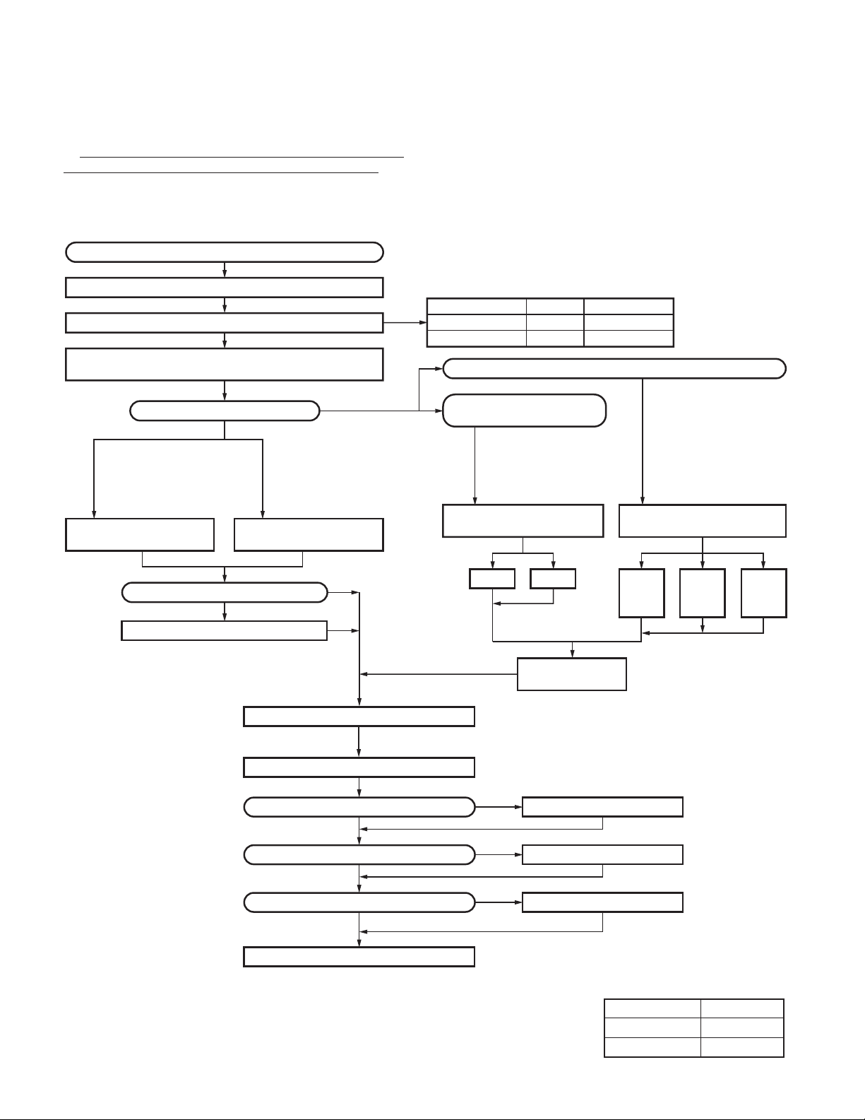
Before Reading About System Set-up
The TK-5810H(B) is a transceiver main unit (without a
panel or speaker) that you complete by adding options.
The options are classified into three types according to
operation and function.
Merchandise received
License and frequency allocated by FCC
Choose the type of transceiver
TK-5810H(B) is complete by combining options
with only the transceiver body (without panel)
Are you using the remote kit?
NO
See page 13*
Please refer to the
KCH-14/15 service manual
(B51-8728-00) for serving
information, such as circuit
diagram, parts list and etc.
KCH-14 (Basic model)
Front panel kit
Are you using the printed keytops?
See page 13*
Supplied accessory keytops
See page 13*
Please refer to the
KCH-14/15 service manual
(B51-8728-00) for serving
information, such as circuit
diagram, parts list and etc.
KCH-15 (Full-featured
model) Front panel kit
YES
SYSTEM SET-UP
1. Install the front panel kit (controller) directly on a radio to
operate it. (Form : Radio + KCH-14/15)
2. Remotely control one radio with one controller. (Form
: Radio + KRK-5 + KCH-14/15 + KCT-22M/M2/M3)
3. Remotely control one radio with two controllers. (Form
: Radio + KRK-6DH + KCH-14/15 (two) + KCT-22M/M2/
M3 (two))
Frequency range
450~520MHz
400~470MHz 50~100W TK-5810H(B) K2
YES
NO
Are you using one radio
with one controller?
See page 14*
YES
Please refer to the
KRK-5/6DH service manual
(B51-8445-20) for serving
information, such as circuit
diagram, parts list and etc.
Single control head remote kit
KCH-14 KCH-15
RF power
50~100W TK-5810H(B) K
Are you using one radio with two controllers?
KRK-5
(Option) (Option)
Type
YES
See page 16*
Please refer to the
KRK-5/6DH service manual
(B51-8445-20) for serving
information, such as circuit
diagram, parts list and etc.
oror or
+
KRK-6DH
KCH-14
+
KCH-15
Dual control head remote kit
KCH-14
KCH-14
KCH-15
+
KCH-15
Transceiver programming
KCT-23 DC cable
Are you using the voice guide & storage unit?
NO
Are you using the external speaker?
NO
Are you using the keypad microphone?
NO
Delivery
Note :
* For the sections where it says "See page XX", refer to the manual of
TK-5810(B)(B51-8780-00).
KCT-22M/M2/M3
Control cable
See page 5*
A personal computer (IBM PC or compatible), programming
interface (KPG-43/43A), USB adapter(KCT-53U), and programming
software (KPG-95D) are required for programming. (The frequency
and signaling data are programmed for the transceiver.)
KCT-23 M2,M4 : TK-5810H(B)
YES
YES
YES
VGS-1
KES-5 or KES-6
KMC-28
See pages 15 and 16*
See page 18*
(Option)
See page 18*
(Option)
(Option)
Desk top microphone KMC-9B
Service manual parts No. list
Model Parts No.
KRK-5/6DH B51-8445-20
KCH-14/15 B51-8728-00
4
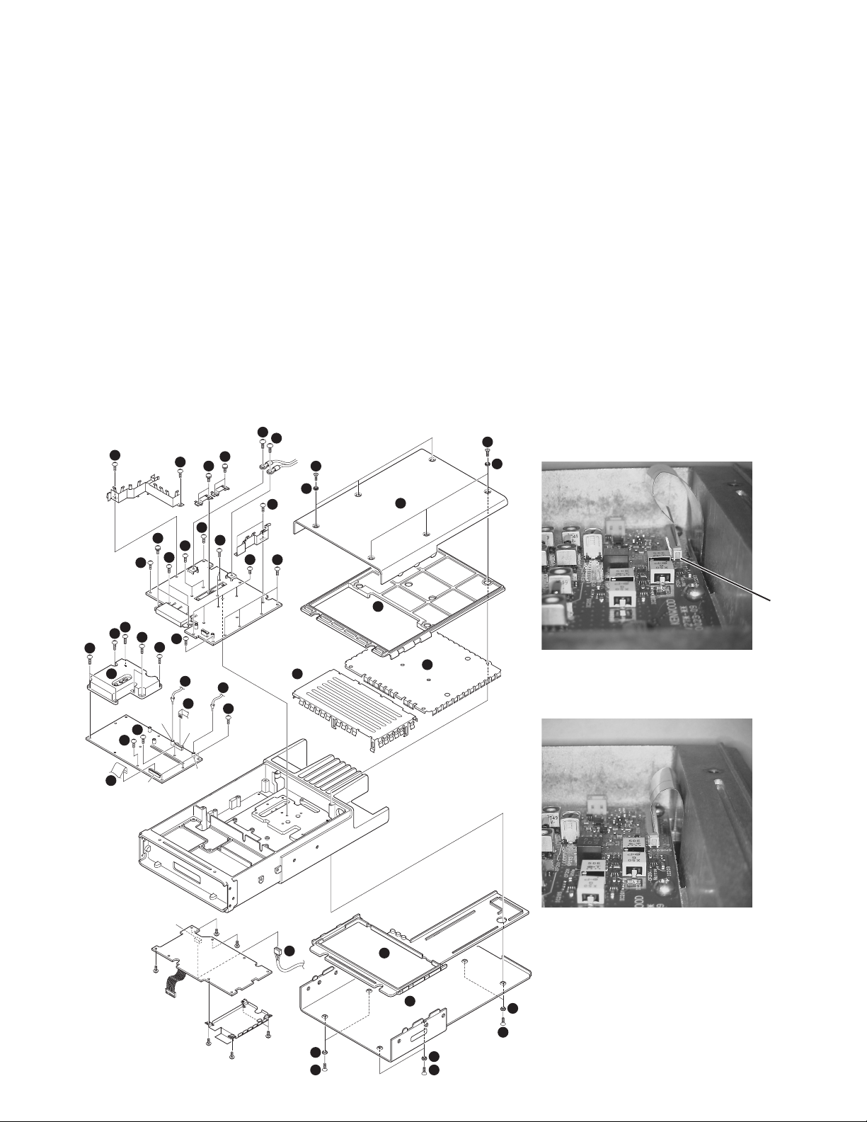
DISASSEMBLY FOR REPAIR
Disassembly Procedure (TK-5810H (B))
■ Removing the upper/ lower case and shield cover
1. Remove the 12 screws z and 12 spacers x.
2. Remove the upper case c and lower case v.
3. Remove the upper packing b and lower packing n.
4. Remove the shielding plate m-1.
5. Remove the shielding plate m-2.
■ Removing the TX-RX unit (X57-727)
1. Remove the 7 screws , holding the PLL shield cover.
2. Remove the PLL shield cover ..
3. Remove the coaxial cables from the two connectors
(CN150, CN200) of the TX-RX unit /.
4. Remove the flat cables from the two connectors (CN600,
CN601) of the TX-RX unit Ω.
5. Remove the 5 screws ≈.
16
16
17
17
14
17
17
15
15
17
17
17
17
17
1
2
4
17
TK-5810H(B
■ Removing the Final unit (X45-380)
1. Remove the cables from the connector (CN702) of the
control unit ç.
2. Remove the 2 screws √ holding the power module.
3. Remove the solder of the power module with a solder
absorber.
4. Remove the 4 screws ∫ holding the two final transistors.
5. Remove the 2 screws ~ holding the + (positive) terminal
and - (negative) terminal of the power supply cable.
6. Remove the 16 screws µ holding the final unit.
7. Remove the solder of the antenna receptacle with a
solder absorber.
Note :
When re-installing the flat cable to the connector on the
CN600 side, do not align the cable as shown in the figure
1, as there is a possibility of producing an effect on the
sensitivity of P25.
1
2
Wrong
)
8
TX-RX
unit
6
8
8
8
17
8
9
12
12
11
CN600
CN150
CN702
10
11
CN601
CN200
10
12
Final unit
Control
unit
7 -1
13
2
1 1
7 -2
Fig. 1
Right
Fig. 2
5
3
2
2
1
CN600
5
TK-5810H(B
)
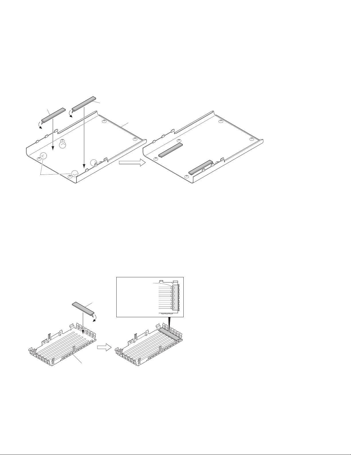
DISASSEMBLY FOR REPAIR
■ Attaching the two new cushions (G13-2195-14)
to the lower case (A01-2164-31)
1. Remove the release paper from the two new cushions.
2. Attach the two cushions by aligning them with the
attaching location marks which are stamped onto the
lower case.
Cushion
Attaching
location mark
■ Attaching the new cushion (G13-2182-04) to the
shielding plate
1. Remove the release paper from the new cushion.
2. Attach the cushion as shown in the figure below.
Notes :
• Ensure you do not overlap the cushion onto the convex
part of the shielding plate.
•
The cushion cannot be reused. Attach a new cushion when
you remove the cushion.
Cushion
Lower case
Ensure you do
not overlap the
cushion onto the
Cushion
Shielding plate
6
convex part of the
shielding plate
CIRCUIT DESCRIPTION
TK-5810H(B
)
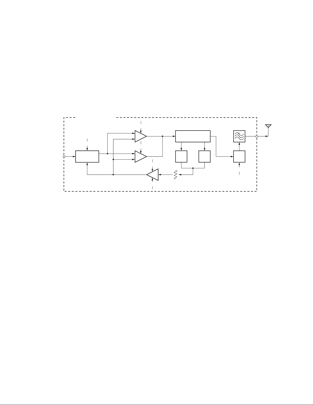
1-1. Final Amplifier Circuit (From Power module to
Antenna output): TK-5810H (B)
The transmit signal from the TX terminal (CN1) of the final
unit (X45-380) is amplified by the power module (IC1).
The signal amplified by the power module is divided into
two signal, and further is amplified by the final amplifier
(Q1,Q2). The each signal from Q1 and Q2 is combined.
The combined signal passes through the antenna switch
(D5, D6, D7, D8, D15, D16), CM coupler and low-pass filter,
then it is fed to the antenna.
CM coupler is a line for detecting forward wave and
reflected wave.
FINAL UNIT (X45-380)
+B
Q1
+B
Q2
IC2
TX(CN1)
+B
IC1
POWER
MODULE
Final AMP
Final AMP
8T
APC
PC
Forward wave is detected by D2, and is converted into
DC voltage. The converted DC voltage is fed to the APC
comparator (IC2), and is compared with the PC voltage, then
is output from the OUT-B terminal (pin 7) of IC2 as an APC
voltage. The APC voltage controls the gate voltage of the
power module (IC1) and final amplifier (Q1,Q2), and keeps
transmission output stable.
If an abnormal antenna load is connected, reflected wave
is detected by D3, and output voltage (DC voltage) is fed to
the APC comparator (IC2). The transmission output is
reduced more as this DC voltage rises.
ANT
LPF
CM
COUPLER
D5,D6,D7
D8,D15,D16
ANT
SW
8T
VR1
D2
FWD
DET
D3
REFL
DET
Fig. 1 Final amplifier circuit: TK-5810H (B)
1-2. Temperature Protection Circuit : TK-5810H (B)
To prevent thermal destruction of the power module
(IC1) and final amplifier (Q1,Q2), this circuit reduces APC
voltage when temperature of the power module (IC1) and
final amplifier (Q1,Q2) rises.
The CPU (IC703) detects temperature with the
thermistor (TH1,TH3) and controls reference voltage to the
APC circuit.
7
TK-5810H(B
)
COMPONENTS DESCRIPTION
TX-RX unit (X57-7270-XX)
Ref. No. Part name Description
IC200 IC DBM
IC201~203 IC Multiplexer
IC204 IC OP AMP
IC205~207 IC Multiplexer
IC209 IC FM IC
IC210 IC Buffer
IC211 IC Multiplexer
IC400 IC PLL IC
IC401 IC Potentiometer
IC402 IC DC/DC
IC403 IC VCO Tune
IC600 IC Shift register
IC601 IC Voltage regulator (5V)
Q150,151,200
Q201,202 Transistor DC switch
Q203 Transistor Local AMP
Q204,205 Transistor IF AMP
Q207 Transistor VCXO frequency AMP
Q208,209 Transistor DC switch
Q210 FET DC switch
Q211 Transistor Noise AMP
Q400 FET CV detection
Q401,402 Transistor UL detection
Q403 Transistor PLL Fin AMP
Q404 Transistor TX/RX switch
Q405 FET TX/RX switch
Q406 FET DC/DC
Q407 Transistor VCO1/2 switch
Q408 FET VCO1/2 switch
Q409,410 Transistor VCO1/2 switch
Q411,412 Transistor Ripple filter
Q413~415 FET VCO oscillator
Q416 Transistor Buffer AMP
Q417 Transistor PLL Fin AMP
Q418 Transistor Buffer AMP
Q600,601 Transistor 8T switch
Q602,603 Transistor 8R switch
D200~203
D204~207
D208~217 Diode IF filter switch
D400 Diode Ripple filter
D401 Diode Assist DC
D402,403
D405~409
D411~414
D416,417
D418
D419,420 Diode TX/RX switch
D421,422
Transistor RF AMP
Variable capacitance diode
Variable capacitance diode
Variable capacitance diode
Variable capacitance diode
Variable capacitance diode
Variable capacitance diode
Variable capacitance diode
Variable capacitance diode
HPF control
BPF control
VCO control
VCO control
VCO control
VCO control
Modulation
VCO control
Final unit (X45-3800-10:K X45-3800-11:K2)
Ref. No. Part name Description
IC1 IC TX drive AMP
IC2 IC DC AMP and APC comparator
Q1,2 FET Final AMP
D1 Zener diode Protect of voltage
D2 Diode Forward wave rectification
D3 Diode Reflected wave rectification
D4 Diode Combiner
D5~8 Diode ANT switch
D10 Diode Surge absorption
D13 Diode Protect of reverse connection
D14 Diode Surge absorption
D15,16 Diode ANT switch
8
TERMINAL FUNCTION
Final unit (X45-3800-10:K X45-3800-11:K2)
Pin
No.
1TXITX drive input
1 FTEMP2 O Final unit temperature 2
2 FTEMP1 O Final unit temperature 1
38T − 8V input during transmission
48T − 8V input during transmission
5E − GND
6PCITX power control voltage
1RXORX signal output
1+BIPower supply input (13.4V±15%)
1E − GND
1+BOPower supply output (13.4V±15%)
2+BOPower supply output (13.4V±15%)
3E − GND
Name I/O Description
CN1 (to TX-RX unit CN152)
CN2 (to TX-RX unit CN601)
CN4 (to TX-RX unit CN200)
CN5 (to DC cable)
CN6 (to DC cable)
W1 (to Control unit CN702)
TK-5810H(B
)
9
TK-5810H(B
)
PARTS LIST
New Parts. indicates safety critical components.
∗
Parts without Parts No. are not supplied.
Les articles non mentionnes dans le Parts No. ne sont pas fournis.
Teile ohne Parts No. werden nicht geliefert.
TK-5810H(B) (Y51-5120-XX)
FINAL UNIT (X45-3800-XX)
Ref. No.
Address
New
Parts No. Description
parts
TK-5810H(B) -10:K -11:K2
33A A01-2163-21 METALLIC CABINET(UPPER)
41B∗ A01-2164-31 METALLIC CABINET(LOWER)
72A∗ A10-4115-01 CHASSIS
10 2C B62-1938-00 INSTRUCTION MANUAL
14 2B E04-0167-15 RF COAXIAL RECEPTACLE(M)
15 1A E37-0179-05
16 1C E37-0733-05 SHORT PLUG(SP) ACCESSORY
17 2B E37-0773-35 LEAD WIRE WITH CONNECTOR(D-SUB)
18 2A,3A ∗ E37-1147-15 FLAT CABLE(X53:CN782-X57:CN600)
20 2B ∗ E37-1150-25
22 1A,2A E37-1156-05 FLAT CABLE(X45:CN2-X57:CN601)
26 1B F10-1488-02 SHIELDING PLATE(FINAL:X45)
27 1A F10-2265-13 SHIELDING COVER(VCO,TX-RX:X57)
28 3A F10-3012-04 SHIELDING PLATE(CONTROL:X53)
29 1A F10-3015-04 SHIELDING PLATE(X45 LPF)
30 1A F10-3039-04 SHIELDING PLATE(X45 DC)
31 2A F10-3040-04 SHIELDING PLATE(X45 ACC)
32 1B ∗ F10-3069-12 SHIELDING PLATE(X57:TX-RX)
33 3A G02-0599-04 FLAT SPRING(AVR)
34 3A G02-0709-04 FLAT SPRING(AUDIO AMP)
LEAD WIRE WITH MINIPIN PLUG(X45-X57)
LEAD WIRE WITH CONNECTOR(DC4P/ACC9P)
L:
Scandinavia
Y:
PX (Far East, Hawaii)
Y:
AAFES (Europe)
Destination Destination
Ref. No.
C12 CK73GB1H471K CHIP C 470PF K
C14 CK73GB1H471K CHIP C 470PF K
C15 C93-0599-05 CHIP C 470PF K
C16 CK73GB1H471K CHIP C 470PF K
C18 C93-0553-05 CHIP C 3.0PF C K
C18 C93-0554-05 CHIP C 4.0PF C K2
C19 C93-0552-05 CHIP C 2.0PF C
C20 ,21 C93-0567-05 CHIP C 39PF J
C24 ,25 C93-0599-05 CHIP C 470PF K
C27 CK73GB1H471K CHIP C 470PF K
C29 ,30 C93-0555-05 CHIP C 5.0PF C K
C29 ,30 C93-0560-05 CHIP C 10PF D K2
C31 CK73GB1H471K CHIP C 470PF K
C32 CK73GB1C104K CHIP C 0.10UF K
C33 ,34 C93-0553-05 CHIP C 3.0PF C K
C33 ,34 C93-0556-05 CHIP C 6.0PF D K2
C35 ∗ CM73F2H300F CHIP C 30PF F K
C35 ∗ CM73F2H390F CHIP C 39PF F K2
C36 CM73F2H070D CHIP C 7.0PF D K
C36 CM73F2H120J CHIP C 12PF J K2
C37 CK73GB1H471K CHIP C 470PF K
Address
K:
New
parts
USA
T:
England
X:
Australia
P:
Canada
E:
Europe
M:
Other Areas
Parts No. Description
35 1A ∗ G02-1834-04 EARTH SPRING(FINAL AMP)
36 2B G10-1327-04 FIBROUS SHEET
38 2A,1C G11-4379-04 SHEET ACCESSORY
39 2B G13-2182-04 CUSHION(X57 SHELDING PLATE)
40 1B G13-2195-14 CUSHION(BOTTOM CABINET)
41 2B G53-1626-03 PACKING(D-SUB CAP)
42 2B G53-1657-04 PACKING(ANT)
44 2B G53-1659-04 PACKING(DC/ACC)
47 3A G53-1667-11 PACKING(TOP)
48 1B G53-1668-11 PACKING(BOTTOM)
49 2B G53-1687-04 PACKING(D-SUB)
50 1C H02-0626-04 INNER CARTON CASE
51 2C H12-3176-02 PACKING FIXTURE(HEAD-SPACE)
53 2C,3C H12-3185-02 PACKING FIXTURE(TOP,BOTTOM)
58 3C ∗ H52-2129-02 ITEM CARTON CASE
62
A2B N09-2292-05 HEXAGON HEAD SCREW(D-SUB)
B
E1A N67-3008-48
G2B N68-4006-48
H
I1AN87-2612-48
J2B N87-3008-48
63 1C N99-2051-05 SCREW SET ACCESSORY
65 3A W09-0971-05 LITHIUM CELL(X53)
1B,3A,3B
∗ J39-0651-15 SPACER(TOP,BOTTOM,CABINET)
1B,3A,3B
1A,1B,2A
3A,3B
N32-3008-43
N87-2606-48 BRAZIER HEAD TAPTITE SCREW(PCB)
FLAT HEAD MACHINE SCREW(CABNET)
PAN HEAD SEMS SCREW(POWER MODULE)
PAN HEAD SEMS SCREW(DC TERMINAL)
BRAZIER HEAD TAPTITE SCREW(SHIELD)
BRAZIER HEAD TAPTITE SCREW(DC/ACC,ANT)
FINAL UNIT (X45-3800-XX) -10:K -11:K2
C1 -4 CK73GB1H471K CHIP C 470PF K
C7 CK73GB1H471K CHIP C 470PF K
C8 CK73FB1H471K CHIP C 470PF K
C10 ,11 CK73FB1H471K CHIP C 470PF K
C38 ,39 ∗ CM73F2H300F CHIP C 30PF F K
C38 ,39 ∗ CM73F2H390F CHIP C 39PF F K2
C40 CM73F2H070D CHIP C 7.0PF D K
C40 CM73F2H120J CHIP C 12PF J K2
C41 ∗ CM73F2H300F CHIP C 30PF F K
C41 ∗ CM73F2H390F CHIP C 39PF F K2
C42 C93-0599-05 CHIP C 470PF K
C43 CM73F2H270F CHIP C 27PF F K
C43 ∗ CM73F2H300F CHIP C 30PF F K2
C44 C93-0599-05 CHIP C 470PF K
C45 ∗ CM73F2H300F CHIP C 30PF F K2
C45 -47 CM73F2H270F CHIP C 27PF F K
C46 ,47 CM73F2H270F CHIP C 27PF F K2
C48 ,49 CM73F2H080C CHIP C 8.0PF C K
C48 ,49 ∗ CM73F2H200C CHIP C 20PF C K2
C51 ,52 CK73FB1H471K CHIP C 470PF K
C53 ,54 CM73F2H020C CHIP C 2.0PF C K
C55 ,56 CK73FB1H103K CHIP C 0.010UF K
C57 ,58 CM73F2H020C CHIP C 2.0PF C K
C57 ,58 ∗ CM73F2H100C CHIP C 10PF C K2
C59 ,60 CK73FB1E104K CHIP C 0.10UF K
C61 ,62 CM73F2H101J CHIP C 100PF J K2
C61 ,62 CM73F2H391J CHIP C 390PF J K
C63 CM73F2H020C CHIP C 2.0PF C K2
C63 CM73F2H1R5C CHIP C 1.5PF C K
C67 CM73F2H010C CHIP C 1.0PF C K
C67 CM73F2H040C CHIP C 4.0PF C K2
C68 ,69 CM73F2H020C CHIP C 2.0PF C K
C71 CK73GB1H471K CHIP C 470PF K
C73 CM73F2H330J CHIP C 33PF J K2
C73 CM73F2H470J CHIP C 47PF J K
C74 ,75 CK73FB1H471K CHIP C 470PF K
C77 CM73F2H270J CHIP C 27PF J K
10
PARTS LIST
TK-5810H(B
)
Ref. No. Parts No. Description
C77 CM73F2H330J CHIP C 33PF J K2
C78 CK73GB1H471K CHIP C 470PF K
C80 C93-0599-05 CHIP C 470PF K
C81 CK73FB1H471K CHIP C 470PF K
C82 CM73F2H040C CHIP C 4.0PF C K
C82 ∗ CM73F2H090C CHIP C 9.0PF C K2
C83 CM73F2H101J CHIP C 100PF J K2
C83 CM73F2H391J CHIP C 390PF J K
C84 CM73F2H040C CHIP C 4.0PF C
C85 CC73FCH1H101J CHIP C 100PF J
C87 ∗ CM73F2H070C CHIP C 7.0PF C
C88 CC73FCH1H080D CHIP C 8.0PF D
C89 ∗ CM73F2H070C CHIP C 7.0PF C K
C89 CM73F2H080C CHIP C 8.0PF C K2
C90 CK73FB1H471K CHIP C 470PF K
C93 CC73FCH1H020C CHIP C 2.0PF C K2
C94 ∗ CM73F2H070C CHIP C 7.0PF C K
C94 CM73F2H080C CHIP C 8.0PF C K2
C95 CK73FB1H471K CHIP C 470PF K
C96 ∗ CM73F2H070C CHIP C 7.0PF C
C98 CM73F2H050C CHIP C 5.0PF C K
C98 ∗ CM73F2H070C CHIP C 7.0PF C K2
C101 CK73FB1H471K CHIP C 470PF K
C102,103 CK73GB1H471K CHIP C 470PF K
C104 CK73GB1H103K CHIP C 0.010UF K
C105,106 ∗ CM73F2H100C CHIP C 10PF C K
C105,106 ∗ CM73F2H180C CHIP C 18PF C K2
C107,108 CM73F2H030C CHIP C 3.0PF C K
C109 CC73FCH1H470J CHIP C 47PF J K
C109 CC73FCH1H560J CHIP C 56PF J K2
C110 CK73FB1H471K CHIP C 470PF K
C116,117 CK73GB1H471K CHIP C 470PF K
C119,120 CK73GB1H471K CHIP C 470PF K
C122,123 CK73GB1H471K CHIP C 470PF K
C124 CC73GCH1H270J CHIP C 27PF J
C125,126 CK73GB1H471K CHIP C 470PF K
C131,132 CC73GCH1H270J CHIP C 27PF J
C133,134 CK73GB1H471K CHIP C 470PF K
C135 CK73GB1C104K CHIP C 0.10UF K
C136 CK73GB1H103K CHIP C 0.010UF K
C138 CC73GCH1H270J CHIP C 27PF J
C139,140 C92-0777-05 ELECTRO 1000UF 25WV
C141,142 C90-4126-05 ELECTRO 680UF 25WV
C143 C90-4126-05 ELECTRO 680UF 25WV
Address
New
parts
FINAL UNIT (X45-3800-XX)
Destination Destination
Ref. No. Parts No. Description
L16 ,17 ∗ L34-4875-05 AIR-CORE COIL
L18 L41-8275-33 SMALL FIXED INDUCTOR(0.082UH) K
L18 ,19 L41-1085-33 SMALL FIXED INDUCTOR(0.1UH) K2
L19 L41-1085-33 SMALL FIXED INDUCTOR(0.1UH) K
R1 RK73FB2B821J CHIP R 820 J 1/8W K
R2 RK73FB2B000J CHIP R 0.0 J 1/8W K2
R2 ,3 RK73FB2B100J CHIP R 10 J 1/8W K
R4 RK73FB2B821J CHIP R 820 J 1/8W K
R5 RK73FB2B000J CHIP R 0.0 J 1/8W
R6 RK73GB2A183J CHIP R 18K J 1/10W
R7 RK73GB2A821J CHIP R 820 J 1/10W K2
R7 -9 RK73GB2A000J CHIP R 0.0 J 1/10W K
R8 ,9 RK73GB2A000J CHIP R 0.0 J 1/10W K2
R10 RK73GB2A103J CHIP R 10K J 1/10W
R11 RK73GB2A123J CHIP R 12K J 1/10W
R12 RK73GB2A000J CHIP R 0.0 J 1/10W
R13 -15 ∗ RK73PB2H150J CHIP R 15 J 1/2W K2
R13 ,14 ∗ RK73PB2H150J CHIP R 15 J 1/2W K
R15 -18 RK73PB2H180J CHIP R 18 J 1/2W K
R16 ,17 RK73PB2H180J CHIP R 18 J 1/2W K2
R18 ∗ RK73PB2H150J CHIP R 15 J 1/2W K2
R19 RK73GB2A000J CHIP R 0.0 J 1/10W
R20 RK73GB2A224J CHIP R 220K J 1/10W K2
R20 RK73GB2A274J CHIP R 270K J 1/10W K
R21 RK73GB2A101J CHIP R 100 J 1/10W
R22 ,23 ∗ RK73PB2H471J CHIP R 470 J 1/2W
R24 RK73GB2A224J CHIP R 220K J 1/10W K
R24 RK73GB2A274J CHIP R 270K J 1/10W K2
R25 RK73GB2A124J CHIP R 120K J 1/10W K
R25 RK73GB2A334J CHIP R 330K J 1/10W K2
R26 RK73GB2A332J CHIP R 3.3K J 1/10W K2
R26 RK73GB2A472J CHIP R 4.7K J 1/10W K
R27 RK73GB2A102J CHIP R 1.0K J 1/10W
R28 RK73GB2A000J CHIP R 0.0 J 1/10W
R29 RK73GB2A104J CHIP R 100K J 1/10W
R30 RK73GB2A102J CHIP R 1.0K J 1/10W K2
R31 RK73GB2A000J CHIP R 0.0 J 1/10W
R36 RK73GB2A104J CHIP R 100K J 1/10W
R39 RK73GB2A103J CHIP R 10K J 1/10W K2
R39 RK73GB2A224J CHIP R 220K J 1/10W K
R40 RK73GB2A000J CHIP R 0.0 J 1/10W
R42 RK73FB2B560J CHIP R 56 J 1/8W K
R42 RK73FB2B820J CHIP R 82 J 1/8W K2
R45 RK73GB2A224J CHIP R 220K J 1/10W K2
Address
New
parts
CN1 ,4 E04-0154-05 PIN SOCKET
CN5 ,6 E23-1116-05 RELAY TERMINAL
CN3 E23-1118-05 TERMINAL
W1 ∗ E37-1218-05 LEAD WIRE WITH CONNECTOR
CN2 E40-6429-05 FLAT CABLE CONNECTOR
L1 ,2 L92-0179-05 CHIP FERRITE
L3 ,4 L34-4518-05 AIR-CORE COIL
L5 ,6 L92-0179-05 CHIP FERRITE
L7 ,8 L34-4520-05 AIR-CORE COIL
L9 ,10 L92-0179-05 CHIP FERRITE
L11 ,12 L34-4518-05 AIR-CORE COIL
L13 L34-4523-05 AIR-CORE COIL
L14 ,15 ∗ L34-4875-05 AIR-CORE COIL
R45 RK73GB2A563J CHIP R 56K J 1/10W K
R46 RK73FB2B221J CHIP R 220 J 1/8W K
R46 RK73FB2B331J CHIP R 330 J 1/8W K2
R47 RK73GB2A000J CHIP R 0.0 J 1/10W K2
R47 RK73GB2A103J CHIP R 10K J 1/10W K
R49 RK73FB2B181J CHIP R 180 J 1/8W K2
R49 RK73FB2B391J CHIP R 390 J 1/8W K
R50 RK73FB2B680J CHIP R 68 J 1/8W K
R50 RK73FB2B820J CHIP R 82 J 1/8W K2
R54 RK73GB2A000J CHIP R 0.0 J 1/10W
R55 ,56 RK73PB2H101J CHIP R 100 J 1/2W
R57 RK73FB2B224J CHIP R 220K J 1/8W
R59 RS14DB3F101J FL-PROOF RS 100 J 3W
VR1 R12-6431-05 TRIMMING POT.(220K)
If a part reference number is listed in a shaded box, that part does not come with the PCB.
11
TK-5810H(B
)
FINAL UNIT (X45-3800-XX)
TX-RX UNIT (X57-7270-XX)
Ref. No. Parts No. Description
D1 UDZS5.6B ZENER DIODE
D2 ,3 HSM88AS-E DIODE
D4 MA2S111-F DIODE
D5 ,6 MA4P4002F DIODE
D7 ,8 MA4PH633 DIODE
D10 ZSH5MA27 SURGE ABSORBER
D13 DF25V60 DIODE
D14 ∗ CSA70-401L SURGE ABSORBER
D15 ,16 HVC131 DIODE
Address
New
parts
PARTS LIST
Destination Destination
Ref. No. Parts No. Description
C214 CC73GCH1H150J CHIP C 15PF J K
C216 CK73GB1H471K CHIP C 470PF K
C218 CC73GCH1H080B CHIP C 8.0PF B K2
C218 CC73GCH1H100C CHIP C 10PF C K
C220-223 CK73GB1H471K CHIP C 470PF K
C224 CC73GCH1H180J CHIP C 18PF J K2
C224 CC73GCH1H220J CHIP C 22PF J K
C225 CC73GCH1H090B CHIP C 9.0PF B K
C225 CC73GCH1H100C CHIP C 10PF C K2
Address
New
parts
IC1 ∗ RA13H4047M123 MOS-IC K2
IC1 ∗ RA13H4452M123 MOS-IC K
IC2 TA75W01FUF MOS-IC
Q1 ,2 RD60HUF1-101 FET
TH1 S1R104J475H THERMISTOR
TH3 S1R104J475H THERMISTOR
TX-RX UNIT (X57-7270-XX) -10:K -11:K2
C151 CK73GB1H471K CHIP C 470PF K
C152 CC73GCH1H100C CHIP C 10PF C
C153 CC73GCH1H220J CHIP C 22PF J
C155 CC73GCH1H181J CHIP C 180PF J
C156 CK73GB1H471K CHIP C 470PF K
C157 CC73GCH1H010B CHIP C 1.0PF B K
C157 CC73GCH1H080B CHIP C 8.0PF B K2
C158 CC73GCH1H120J CHIP C 12PF J K
C158 CC73GCH1H180J CHIP C 18PF J K2
C160 CC73GCH1H101J CHIP C 100PF J
C161 CK73GB1H471K CHIP C 470PF K
C162 C92-0865-05 ELECTRO 47UF 20WV
C163 CC73GCH1H050B CHIP C 5.0PF B
C164 CK73GB1H471K CHIP C 470PF K
C165 CC73GCH1H060B CHIP C 6.0PF B K
C165 CC73GCH1H070B CHIP C 7.0PF B K2
C166 CK73GB1H471K CHIP C 470PF K
C167 CC73GCH1H050B CHIP C 5.0PF B
C168 CK73GB1H103K CHIP C 0.010UF K
C169,170 CK73GB1H471K CHIP C 470PF K
C200 CK73GB1H471K CHIP C 470PF K
C201 CC73GCH1H030B CHIP C 3.0PF B K
C201 CC73GCH1H040B CHIP C 4.0PF B K2
C202 CK73GB1H471K CHIP C 470PF K
C203 CC73GCH1H020B CHIP C 2.0PF B K2
C203 CC73GCH1H1R5B CHIP C 1.5PF B K
C204 CC73GCH1H030B CHIP C 3.0PF B K
C204 CC73GCH1H040B CHIP C 4.0PF B K2
C205 CC73GCH1H0R5B CHIP C 0.5PF B K
C205 CC73GCH1H010B CHIP C 1.0PF B K2
C206 CK73GB1H471K CHIP C 470PF K
C207 CC73GCH1H030B CHIP C 3.0PF B
C208 CC73GCH1H0R5B CHIP C 0.5PF B K
C208 CC73GCH1H010B CHIP C 1.0PF B K2
C209,210 CK73GB1H471K CHIP C 470PF K
C211 CC73GCH1H030B CHIP C 3.0PF B K
C211 CC73GCH1H040B CHIP C 4.0PF B K2
C212 CC73GCH1H020B CHIP C 2.0PF B K2
C212 CC73GCH1H1R5B CHIP C 1.5PF B K
C213 CK73GB1H471K CHIP C 470PF K
C214 CC73GCH1H120J CHIP C 12PF J K2
C226 CC73GCH1H030B CHIP C 3.0PF B K
C226 CC73GCH1H050B CHIP C 5.0PF B K2
C227 CC73GCH1H150J CHIP C 15PF J K2
C227 CC73GCH1H180J CHIP C 18PF J K
C228 CC73GCH1H070B CHIP C 7.0PF B K
C228 CC73GCH1H090B CHIP C 9.0PF B K2
C229 CC73GCH1H040B CHIP C 4.0PF B K
C229 CC73GCH1H060B CHIP C 6.0PF B K2
C230 CC73GCH1H150J CHIP C 15PF J K2
C230 CC73GCH1H180J CHIP C 18PF J K
C231 CC73GCH1H070B CHIP C 7.0PF B K
C231 CC73GCH1H090B CHIP C 9.0PF B K2
C232 CC73GCH1H050B CHIP C 5.0PF B
C233 CC73GCH1H220J CHIP C 22PF J K
C233 CC73GCH1H270J CHIP C 27PF J K2
C234 CK73GB1H471K CHIP C 470PF K
C235 CC73GCH1H080B CHIP C 8.0PF B K
C235 CC73GCH1H100C CHIP C 10PF C K2
C236 CK73GB1H471K CHIP C 470PF K
C238,239 CC73GCH1H680J CHIP C 68PF J
C240 CK73GB1H103K CHIP C 0.010UF K
C241,242 CK73GB1H471K CHIP C 470PF K
C243 CK73GB1H103K CHIP C 0.010UF K
C244,245 CC73GCH1H080B CHIP C 8.0PF B
C246 CC73GCH1H050B CHIP C 5.0PF B
C247 CC73GCH1H040B CHIP C 4.0PF B
C248 CC73GCH1H090B CHIP C 9.0PF B
C249,250 CK73GB1H103K CHIP C 0.010UF K
C251 CC73GCH1H050B CHIP C 5.0PF B K
C251 CC73GCH1H080B CHIP C 8.0PF B K2
C252 CC73GCH1H100C CHIP C 10PF C K
C252 CC73GCH1H120J CHIP C 12PF J K2
C253 CC73GCH1H050B CHIP C 5.0PF B K
C253 CC73GCH1H080B CHIP C 8.0PF B K2
C254 CK73GB1H103K CHIP C 0.010UF K
C255 CC73GCH1H100C CHIP C 10PF C
C256 CC73GCH1H090B CHIP C 9.0PF B
C257 CC73GCH1H070B CHIP C 7.0PF B
C260 CC73GCH1H040B CHIP C 4.0PF B K2
C260 CC73GCH1H050B CHIP C 5.0PF B K
C261 CK73GB1H471K CHIP C 470PF K K
C262 CK73GB1H103K CHIP C 0.010UF K
C263 CC73GCH1H101J CHIP C 100PF J K2
C263 CC73GCH1H120J CHIP C 12PF J K
C264 CK73GB1H103K CHIP C 0.010UF K
C265 CK73GB1H471K CHIP C 470PF K K2
C265,266 CK73GB1H471K CHIP C 470PF K K
C266 CC73GCH1H101J CHIP C 100PF J K2
C267 CK73GB1H103K CHIP C 0.010UF K
C268 CC73GCH1H101J CHIP C 100PF J
12
If a part reference number is listed in a shaded box, that part does not come with the PCB.
Ref. No. Parts No. Description
C269 CC73GCH1H120J CHIP C 12PF J
C270 CK73GB1E103K CHIP C 0.010UF K
C271 CK73GB1H102K CHIP C 1000PF K
C272 CK73GB1H103K CHIP C 0.010UF K
C273 CC73GCH1H090B CHIP C 9.0PF B
Address
New
parts
TK-5810H(B
PARTS LIST
TX-RX UNIT (X57-7270-XX)
Destination Destination
Ref. No. Parts No. Description
C416 CS77CA1ER47M CHIP TNTL 0.47UF 25WV K2
C417 C92-0863-05 CHIP TNTL 0.047UF 35WV
C418 CK73GB1C104K CHIP C 0.10UF K
C419 CC73GCH1H470J CHIP C 47PF J
C420 CK73GB1H471K CHIP C 470PF K
Address
New
parts
)
C274 CC73GCH1H080B CHIP C 8.0PF B
C275,276 CC73GCH1H040B CHIP C 4.0PF B
C277 CC73GCH1H090B CHIP C 9.0PF B
C278 CC73GCH1H100C CHIP C 10PF C
C279,280 CK73GB1H103K CHIP C 0.010UF K
C281 CC73GCH1H090B CHIP C 9.0PF B
C282 CC73GCH1H080B CHIP C 8.0PF B
C285,286 CK73GB1H102K CHIP C 1000PF K
C287 CK73GB1H103K CHIP C 0.010UF K
C288-290 CK73GB1C104K CHIP C 0.10UF K
C291 CC73GCH1H470J CHIP C 47PF J
C292 CC73GCH1H101J CHIP C 100PF J
C296 CK73GB1H103K CHIP C 0.010UF K
C298-300 CK73GB1C104K CHIP C 0.10UF K
C302 CK73GB1E103K CHIP C 0.010UF K
C304 CC73GCH1H470J CHIP C 47PF J
C305 CK73GB1E103K CHIP C 0.010UF K
C306 CC73GCH1H101J CHIP C 100PF J
C309-315 CK73GB1C104K CHIP C 0.10UF K
C316 CK73FB0J106K CHIP C 10UF K
C317 CC73GCH1H150J CHIP C 15PF J
C319 CC73GCH1H150J CHIP C 15PF J
C320 CK73GB1C104K CHIP C 0.10UF K
C321,322 CK73GB1E103K CHIP C 0.010UF K
C323 CC73GCH1H030B CHIP C 3.0PF B
C324 CK73GB1C104K CHIP C 0.10UF K
C325 CK73GB1E103K CHIP C 0.010UF K
C326 CS77AA0J100M CHIP TNTL 10UF 6.3WV
C327 CC73GCH1H181J CHIP C 180PF J
C328 CC73GCH1H270J CHIP C 27PF J
C423 CK73GB1H103K CHIP C 0.010UF K
C424 CK73GB1C104K CHIP C 0.10UF K
C425 CC73GCH1H101J CHIP C 100PF J
C427 CK73GB1H102K CHIP C 1000PF K
C430 CK73GB1H471K CHIP C 470PF K
C431 CK73GB1H103K CHIP C 0.010UF K
C432 CK73FB1C334K CHIP C 0.33UF K
C433 CK73GB1C104K CHIP C 0.10UF K
C434 CK73GB1H471K CHIP C 470PF K
C435 CC73GCH1H080B CHIP C 8.0PF B K2
C436 CC73GCH1H060B CHIP C 6.0PF B K2
C436 CC73GCH1H270J CHIP C 27PF J K
C437 CC73GCH1H470J CHIP C 47PF J
C438 CC73GCH1H050B CHIP C 5.0PF B K2
C438,439 CC73GCH1H2R5B CHIP C 2.5PF B K
C439 CC73GCH1H470J CHIP C 47PF J K2
C441 CC73GCH1H020B CHIP C 2.0PF B K
C441 CC73GCH1H1R5B CHIP C 1.5PF B K2
C442 CC73GCH1H020B CHIP C 2.0PF B K2
C442 CC73GCH1H030B CHIP C 3.0PF B K
C443 CC73GCH1H030B CHIP C 3.0PF B K2
C443 CC73GCH1H050B CHIP C 5.0PF B K
C444,445 CK73GB1E105K CHIP C 1.0UF K
C446 CS77AB21C4R7M CHIP TNTL 4.7UF 16WV
C447 CC73GCH1H101J CHIP C 100PF J
C448,449 CK73GB1C104K CHIP C 0.10UF K
C450 CK73GF1A105Z CHIP C 1.0UF Z
C451-456 CK73GB1H471K CHIP C 470PF K
C457 CC73GCH1H020B CHIP C 2.0PF B K2
C457 CC73GCH1H3R5B CHIP C 3.5PF B K
C329 CK73GB1C104K CHIP C 0.10UF K
C330 CC73GCH1H181J CHIP C 180PF J
C331 CK73GB1H152J CHIP C 1500PF J
C332 CK73GB1H102K CHIP C 1000PF K
C333 CK73GB1C333K CHIP C 0.033UF K
C334 CK73GB1C104K CHIP C 0.10UF K
C335 CS77AA0J220M CHIP TNTL 22UF 6.3WV
C336 CK73GB1H102K CHIP C 1000PF K
C337,338 CK73GB1C104K CHIP C 0.10UF K
C340 CK73GB1H102K CHIP C 1000PF K
C341 CK73GB1C104K CHIP C 0.10UF K
C342 CK73GB1A224K CHIP C 0.22UF K
C400 CK73GB1H471K CHIP C 470PF K
C401 CK73GB1E103K CHIP C 0.010UF K
C402,403 CC73GCH1H101J CHIP C 100PF J
C404 CK73GB1C104K CHIP C 0.10UF K
C406 CK73GB1E103K CHIP C 0.010UF K
C407 CC73GCH1H101J CHIP C 100PF J
C408-410 CK73GB1H471K CHIP C 470PF K
C412 CC73GCH1H101J CHIP C 100PF J K
C412,413 CC73GCH1H101J CHIP C 100PF J K2
C413,414 CC73GCH1H470J CHIP C 47PF J K
C414 CC73GCH1H470J CHIP C 47PF J K2
C415 C92-0863-05 CHIP TNTL 0.047UF 35WV
C416 CS77AA1E010M CHIP TNTL 1.0UF 25WV K
C458 CC73GCH1H010B CHIP C 1.0PF B K
C458 CC73GCH1H1R5B CHIP C 1.5PF B K2
C459 CC73GCH1H101J CHIP C 100PF J K
C459 CC73GCH1H470J CHIP C 47PF J K2
C460 CK73GB1E105K CHIP C 1.0UF K
C461 CC73GCH1H181J CHIP C 180PF J
C463 CK73GB1H471K CHIP C 470PF K
C464 CC73GCH1H101J CHIP C 100PF J
C465 CC73GCH1H220J CHIP C 22PF J
C466-468 CK73GB1E105K CHIP C 1.0UF K
C470-472 CK73GB1H471K CHIP C 470PF K
C474 CK73GB1H103K CHIP C 0.010UF K
C475 C93-0787-05 CERAMIC 0.1UF 50WV
C477 CK73GB1H103K CHIP C 0.010UF K
C478 CS77AC1D220M CHIP TNTL 22UF 20WV
C479 CK73GB1H471K CHIP C 470PF K
C480 CS77AC1D220M CHIP TNTL 22UF 20WV
C482,483 CK73GB1H103K CHIP C 0.010UF K
C484 CK73GB1H471K CHIP C 470PF K
C485 CC73GCH1H101J CHIP C 100PF J K
C485 CC73GCH1H270G CHIP C 27PF G K2
C487 CK73GB1H471K CHIP C 470PF K
C488 CC73GCH1H120G CHIP C 12PF G K
C488 CC73GCH1H150G CHIP C 15PF G K2
C489 CC73GCH1H330G CHIP C 33PF G
13
TK-5810H(B
)
TX-RX UNIT (X57-7270-XX)
Ref. No. Parts No. Description
C490 CS77AA1A100M CHIP TNTL 10UF 10WV
C491 CC73GCH1H0R5B CHIP C 0.5PF B K2
C491 CC73GCH1H010B CHIP C 1.0PF B K
C492 CK73GB1H471K CHIP C 470PF K K
C492 CK73GB1H681K CHIP C 680PF K K2
Address
New
parts
PARTS LIST
Destination Destination
Ref. No. Parts No. Description
C609 C92-0870-05 CHIP TNTL 4.7UF 16WV
C610-620 CK73GB1H471K CHIP C 470PF K
C621 CK73GB1H102K CHIP C 1000PF K
C622-630 CK73GB1H471K CHIP C 470PF K
C631,632 CK73GB1H102K CHIP C 1000PF K
Address
New
parts
C494 CC73GCH1H070B CHIP C 7.0PF B
C495 CC73GCH1H1R5B CHIP C 1.5PF B
C496 CC73GCH1H101J CHIP C 100PF J K
C496 CC73GCH1H390J CHIP C 39PF J K2
C497 CC73GCH1H0R5B CHIP C 0.5PF B K2
C497 CC73GCH1H1R5B CHIP C 1.5PF B K
C499 CC73GCH1H090B CHIP C 9.0PF B K2
C499 CC73GCH1H100C CHIP C 10PF C K
C500,501 CK73GB1H471K CHIP C 470PF K
C502 CC73GCH1H020B CHIP C 2.0PF B K
C502 CC73GCH1H2R5B CHIP C 2.5PF B K2
C503 CS77AB21A220M CHIP TNTL 22UF 10WV
C504 CS77AC1A470M CHIP TNTL 47UF 10WV
C505 CK73GB1H103K CHIP C 0.010UF K
C506 CK73GB1H471K CHIP C 470PF K
C508 CK73GB1H471K CHIP C 470PF K
C509 CC73GCH1H050B CHIP C 5.0PF B
C510 CC73GCH1H040B CHIP C 4.0PF B
C511 CC73GCH1H030B CHIP C 3.0PF B
C512 CC73GCH1H0R5B CHIP C 0.5PF B
C513 CK73GB1H471K CHIP C 470PF K
C514 CC73GCH1H060B CHIP C 6.0PF B K
C514 CC73GCH1H070B CHIP C 7.0PF B K2
C515 CC73GCH1H0R5B CHIP C 0.5PF B
C516 CC73GCH1H060B CHIP C 6.0PF B
C517 CC73GCH1H050B CHIP C 5.0PF B
C518 CC73GCH1H0R5B CHIP C 0.5PF B
C519,520 CK73GB1H471K CHIP C 470PF K
C521 CC73GCH1H070B CHIP C 7.0PF B K
C521 CC73GCH1H090B CHIP C 9.0PF B K2
C634 CC73GCH1H1R5B CHIP C 1.5PF B K2
C634 CC73GCH1H470J CHIP C 47PF J K
C635 CC73GCH1H020B CHIP C 2.0PF B
C636,637 CK73GB1C393K CHIP C 0.039UF K K
C638 CK73GB1C683K CHIP C 0.068UF K K
C640 CC73GCH1H050B CHIP C 5.0PF B K
C640 CC73GCH1H120J CHIP C 12PF J K2
C641 CK73GB1H471K CHIP C 470PF K
C642 CC73GCH1H050B CHIP C 5.0PF B K
C642 CC73GCH1H120J CHIP C 12PF J K2
C644-647 CK73GB1H471K CHIP C 470PF K
CN150 E04-0154-05 PIN SOCKET
CN151 E04-0154-05 PIN SOCKET
CN200 E04-0154-05 PIN SOCKET
CN202 E41-2735-05 PIN ASSY
CN207 E41-2735-05 PIN ASSY
CN600 E40-6438-05 FLAT CABLE CONNECTOR
CN601 E40-6429-05 FLAT CABLE CONNECTOR
W400 E37-1235-05 JUMPER WIRE
CF200 L72-1018-05 CERAMIC FILTER
CF201,202 L72-1016-05 CERAMIC FILTER
CF203 L72-1009-05 CERAMIC FILTER
CF204 L72-1018-05 CERAMIC FILTER
L150,151 L40-3975-92 SMALL FIXED INDUCTOR(39NH)
L152 L40-5663-92 SMALL FIXED INDUCTOR(5.6NH)
L153 L40-2275-92 SMALL FIXED INDUCTOR(22NH) K2
L153,154 L40-1875-92 SMALL FIXED INDUCTOR(18NH) K
L154 L40-1875-92 SMALL FIXED INDUCTOR(18NH) K2
C522 CC73GCH1H070B CHIP C 7.0PF B K2
C522,523 CC73GCH1H060B CHIP C 6.0PF B K
C523 CC73GCH1H050B CHIP C 5.0PF B K2
C524 CC73GCH1H0R5B CHIP C 0.5PF B
C525 CK73GB1H471K CHIP C 470PF K
C527 CC73GCH1H050B CHIP C 5.0PF B K2
C527 CC73GCH1H060B CHIP C 6.0PF B K
C529 CK73GB1H471K CHIP C 470PF K
C530 CC73GCH1H040B CHIP C 4.0PF B K
C530 CC73GCH1H050B CHIP C 5.0PF B K2
C531-534 CK73GB1H471K CHIP C 470PF K
C535 CC73GCH1H060B CHIP C 6.0PF B
C536 CK73GB1H471K CHIP C 470PF K
C537 CC73GCH1H050B CHIP C 5.0PF B K
C537 CC73GCH1H060B CHIP C 6.0PF B K2
C538,539 CK73GB1H471K CHIP C 470PF K
C540 CC73GCH1H101J CHIP C 100PF J
C541,542 CK73GB1H471K CHIP C 470PF K
C600 CK73GB1H471K CHIP C 470PF K
C601 C92-0881-05 ELECTRO 47UF 10WV
C602,603 CK73GB1H471K CHIP C 470PF K
C604 CS77CA1C010M CHIP TNTL 1.0UF 16WV
C605 CK73GB1H103K CHIP C 0.010UF K
C606 C92-0887-05 ELECTRO 1.0UF 50WV
C607,608 CK73GB1C104K CHIP C 0.10UF K
14
If a part reference number is listed in a shaded box, that part does not come with the PCB.
L200-204 L34-4604-05 AIR-CORE COIL
L205 L41-1878-08 SMALL FIXED INDUCTOR(18NH)
L206 L92-0140-05 CHIP FERRITE
L207-210 L34-4565-05 AIR-CORE COIL K
L207-210 L34-4566-05 AIR-CORE COIL K2
L211,212 L41-1588-08 SMALL FIXED INDUCTOR(150NH)
L214,215 L39-1498-05 TOROIDAL COIL
L216 L92-0140-05 CHIP FERRITE
L217,218 L34-4748-05 COIL
L219 L39-1498-05 TOROIDAL COIL
L220,221 L41-1578-08 SMALL FIXED INDUCTOR(15NH) K
L220,221 L41-2278-08 SMALL FIXED INDUCTOR(22NH) K2
L222,223 L34-4749-05 COIL
L224 L41-1878-08 SMALL FIXED INDUCTOR(18NH) K
L224 L41-3378-08 SMALL FIXED INDUCTOR(33NH) K2
L225 L40-6881-37 SMALL FIXED INDUCTOR(0.680UH)
L226 L41-1008-08 SMALL FIXED INDUCTOR(10UH)
L227,228 L34-4748-05 COIL
L229,230 L34-4749-05 COIL
L231 L41-1008-08 SMALL FIXED INDUCTOR(10UH)
L232 L40-5681-86 SMALL FIXED INDUCTOR(0.56UH)
L234 L34-4725-05 COIL
L401 L40-8265-92 SMALL FIXED INDUCTOR(8.2NH)
L402,403 L41-1578-14 SMALL FIXED INDUCTOR(15NH) K2
L403,404 L41-4763-14 SMALL FIXED INDUCTOR(4.7NH) K
PARTS LIST
Ref. No. Parts No. Description
L405 L41-3363-14 SMALL FIXED INDUCTOR(3.3NH) K
L405 L41-6868-14 SMALL FIXED INDUCTOR(6.8NH) K2
L406 L33-1462-05 SMALL FIXED INDUCTOR
L407 L41-3363-14 SMALL FIXED INDUCTOR(3.3NH) K
L407 L41-6868-14 SMALL FIXED INDUCTOR(6.8NH) K2
L408-417 L92-0140-05 CHIP FERRITE
L418-423 L41-1098-08 SMALL FIXED INDUCTOR(1.0UH)
L424 L92-0140-05 CHIP FERRITE
L425-430 L41-1098-08 SMALL FIXED INDUCTOR(1.0UH)
L431 L34-4607-05 AIR-CORE COIL K
L431 L34-4608-05 AIR-CORE COIL K2
L432,433 L41-1098-08 SMALL FIXED INDUCTOR(1.0UH)
L434 L34-4608-05 AIR-CORE COIL K
L434 L34-4609-05 AIR-CORE COIL K2
L435,436 L41-1098-08 SMALL FIXED INDUCTOR(1.0UH)
L437 L34-4608-05 AIR-CORE COIL K
L437 L34-4609-05 AIR-CORE COIL K2
L438,439 L41-1098-08 SMALL FIXED INDUCTOR(1.0UH)
L441 L40-2775-92 SMALL FIXED INDUCTOR(27NH) K2
L441-444 L40-1875-92 SMALL FIXED INDUCTOR(18NH) K
L442,443 L40-1875-92 SMALL FIXED INDUCTOR(18NH) K2
L444 L40-1575-92 SMALL FIXED INDUCTOR(15NH) K2
X200 L77-1961-05 VCXO (16.8MHZ)
X400 L77-3013-05 TCXO (16.8MHZ)
XF200 L71-0625-05 CRYSTAL FILTER (49.95MHZ WIDE)
XF201 L71-0626-05 CRYSTAL FILTER (49.95MHZ NARROW)
R150,151 RK73GB2A821J CHIP R 820 J 1/10W
R152 RK73GB2A5R6J CHIP R 5.6 J 1/10W
R154 RK73GB2A000J CHIP R 0.0 J 1/10W
R155 RK73GB2A123J CHIP R 12K J 1/10W
R156 RK73FB2B470J CHIP R 47 J 1/8W
R158 RK73FB2B101J CHIP R 100 J 1/8W
R159 RK73GB2A000J CHIP R 0.0 J 1/10W
R160 RK73GB2A102J CHIP R 1.0K J 1/10W
R161 RK73GB2A101J CHIP R 100 J 1/10W
R162 RK73GB2A332J CHIP R 3.3K J 1/10W
R163 RK73FB2B100J CHIP R 10 J 1/8W
R165 RK73FB2B100J CHIP R 10 J 1/8W
R166,167 RK73FB2B271J CHIP R 270 J 1/8W
R168 RK73FB2B180J CHIP R 18 J 1/8W K2
R168 RK73FB2B220J CHIP R 22 J 1/8W K
R201-204 RK73GB2A104J CHIP R 100K J 1/10W
R205,206 RK73GB2A183J CHIP R 18K J 1/10W
R208 RK73GB2A221J CHIP R 220 J 1/10W
R209,210 RK73GB2A000J CHIP R 0.0 J 1/10W
R211-215 RK73GB2A104J CHIP R 100K J 1/10W
R216 RK73GB2A000J CHIP R 0.0 J 1/10W
R219 RK73GB2A821J CHIP R 820 J 1/10W K2
R220 RK73GB2A000J CHIP R 0.0 J 1/10W K
R220 RK73GB2A5R6J CHIP R 5.6 J 1/10W K2
R221 RK73GB2A821J CHIP R 820 J 1/10W K2
R222 RK73GB2A470J CHIP R 47 J 1/10W
R223 RK73GB2A102J CHIP R 1.0K J 1/10W
R225 RK73GB2A390J CHIP R 39 J 1/10W
R226 RK73GB2A222J CHIP R 2.2K J 1/10W
R227 RK73GB2A470J CHIP R 47 J 1/10W
R228 RK73GB2A222J CHIP R 2.2K J 1/10W
R229,230 RK73GB2A102J CHIP R 1.0K J 1/10W
Address
New
parts
TK-5810H(B
)
TX-RX UNIT (X57-7270-XX)
Destination Destination
Ref. No. Parts No. Description
R231 RK73FB2B181J CHIP R 180 J 1/8W K
R231 RK73FB2B271J CHIP R 270 J 1/8W K2
R232 RK73FB2B180J CHIP R 18 J 1/8W K2
R232 RK73FB2B330J CHIP R 33 J 1/8W K
R233 RK73FB2B181J CHIP R 180 J 1/8W K
R233 RK73FB2B271J CHIP R 270 J 1/8W K2
R234 RK73GB2A102J CHIP R 1.0K J 1/10W
R235 RK73GB2A222J CHIP R 2.2K J 1/10W
R236 RK73GB2A221J CHIP R 220 J 1/10W K
R236 RK73GB2A680J CHIP R 68 J 1/10W K2
R237 RK73GB2A103J CHIP R 10K J 1/10W K
R237 RK73GB2A561J CHIP R 560 J 1/10W K2
R238 RK73GB2A102J CHIP R 1.0K J 1/10W
R239 RK73GB2A181J CHIP R 180 J 1/10W K
R239 RK73GB2A271J CHIP R 270 J 1/10W K2
R240 RK73GB2A180J CHIP R 18 J 1/10W K2
R240 RK73GB2A330J CHIP R 33 J 1/10W K
R241 RK73GB2A181J CHIP R 180 J 1/10W K
R241 RK73GB2A271J CHIP R 270 J 1/10W K2
R242 RK73GB2A330J CHIP R 33 J 1/10W K2
R242 RK73GB2A331J CHIP R 330 J 1/10W K
R243 RK73GB2A183J CHIP R 18K J 1/10W K
R243 RK73GB2A392J CHIP R 3.9K J 1/10W K2
R244 RK73GB2A560J CHIP R 56 J 1/10W
R245 RK73GB2A270J CHIP R 27 J 1/10W
R246 RK73GB2A222J CHIP R 2.2K J 1/10W
R247,248 RK73GB2A102J CHIP R 1.0K J 1/10W
R249 RK73GB2A182J CHIP R 1.8K J 1/10W
R250 RK73GB2A153J CHIP R 15K J 1/10W
R251 RK73GB2A682J CHIP R 6.8K J 1/10W
R252 RK73GB2A000J CHIP R 0.0 J 1/10W
R253 RK73GB2A102J CHIP R 1.0K J 1/10W
R254 RK73GB2A222J CHIP R 2.2K J 1/10W
R255 RK73GB2A473J CHIP R 47K J 1/10W
R256 RK73GB2A102J CHIP R 1.0K J 1/10W
R258 RK73GB2A000J CHIP R 0.0 J 1/10W
R261 RK73GB2A000J CHIP R 0.0 J 1/10W
R264 RK73GB2A102J CHIP R 1.0K J 1/10W
R265 RK73GB2A104J CHIP R 100K J 1/10W
R266 RK73GB2A000J CHIP R 0.0 J 1/10W
R268,269 RK73GB2A000J CHIP R 0.0 J 1/10W
R271 RK73GB2A104J CHIP R 100K J 1/10W
R272 RK73GB2A473J CHIP R 47K J 1/10W
R274 RK73GB2A182J CHIP R 1.8K J 1/10W
R275 RK73GB2A122J CHIP R 1.2K J 1/10W
R276 RK73GB2A182J CHIP R 1.8K J 1/10W
R277 RK73GB2A122J CHIP R 1.2K J 1/10W
R284 RK73GB2A103J CHIP R 10K J 1/10W
R287,288 RK73GB2A000J CHIP R 0.0 J 1/10W
R293,294 RK73GB2A000J CHIP R 0.0 J 1/10W
R296 RK73GB2A331J CHIP R 330 J 1/10W
R297 RK73GB2A470J CHIP R 47 J 1/10W
R298 RK73GB2A681J CHIP R 680 J 1/10W
R299 RK73GB2A822J CHIP R 8.2K J 1/10W
R300 RK73GB2A470J CHIP R 47 J 1/10W
R301 RK73GB2A684J CHIP R 680K J 1/10W
R304-311 RK73GB2A000J CHIP R 0.0 J 1/10W
R312 RK73GB2A102J CHIP R 1.0K J 1/10W
R313,314 RK73GB2A220J CHIP R 22 J 1/10W
Address
New
parts
If a part reference number is listed in a shaded box, that part does not come with the PCB.
15