

Page 1

KSC-SW11
POWERED ENCLOSED SUBWOOFER
INSTRUCTION MANUAL
CAISSON D’EXTRÊME GRAVE AMPLIFIÉ
MODE D'EMPLOI
GEKAPSELTER SUBWOOFER MIT VERSTÄRKER
BEDIENUNGSANLEITUNG
SUBWOOFER MET SPANNINGSCIRCUIT
GEBRUIKSAANWIJZING
ENGLISH FRANÇAIS DEUTSCH NEDERLANDS
B61-1376-20/01 (W)
©
Page 2
IMPORTANT SAFETY INSTRUCTIONS
Caution: Read this page carefully to ensure safe operation.
WARNING WARNING
• Before mounting or wiring etc., be sure to remove the
wire from the battery minus terminal.
(Not doing so can cause shorts or fires.)
• When extending the ignition, battery, or ground wires,
make sure to use automotive-grade wires or other wires
with a 0.75mm
ration and damage to the wore coating.
• To prevent a short circuit, never put or leave any metallic
objects (such as coins or metal tools) inside the speaker.
• In the event the unit generates smoke or abnormal smell,
immediately s witch the power OFF. Af ter this, please
contact your dealer or nearest service station as soon as
possible.
POWER OFF!
• Connect the speaker to DC 12V, negative ground.
• Do not attempt to open or modif y the unit, for this could
cause fire hazard or malfunction.
• After taking the unit out of the polyethylene bag, be sure
to dispose of the polyethylene bag out of the reach of
children. Otherwise, they may play with the bag, which
could cause hazard of suffocation.
2
(AWG18) or more to prevent wire deterio-
CAUTION CAUTION
• Installation and wiring of the product requires expert skill
and experience. To ensure safet y, be sure to have your
dealer or specialist perform the installation and wiring.
• Do not install the speaker in a spot exposed to direct sunlight or excessive heat or humidity.
• Do not install the sp eakers in lo cations which may be
subject to water or moisture.
• Do not install the speakers in unstable locations or locations subject to dust.
• If the fuse blows, after checking to see if the wiring cord
ENGLISH
has shorted, be sure to replace with the stipulated size
(amperage) fuse as displayed on the fuse box.
(Using fuses other than the stipulated size can cause fires.)
Check the display!
To replace the fuse, refer to the vehicle instruction manu-
al.
• To prevent a short circuit when replacing a fuse, disconnect the wiring harness at first.
• Do not use gasoline, naphtha, or any type of solvent to
clean the speaker. Clean by wiping with a soft, dry cloth.
• Connect the speaker wires to appropriate speaker connector s separate ly. Sha ri ng t he n egative wire o f th e
speaker or grounding speaker wires to the metal body of
the car can cause this unit to fail.
• When mak ing a hole under a seat, inside the trunk, or
somewhere else in the vehicle, check that there is nothing hazardous on the opposite side such as a gasoline
tank, brake pipe; or wiring harness, and be careful not to
cause scratches or other damage.
• For ground wire mounting, do not fasten the wire to an
airbag, steering or brake line system or other critical safety unit bolts or nut.
(Can cause accidents.)
• When mounting, b e sure to mount in a place that will
not interfere with driving or be dangerous to passengers
during sudden braking etc.
(Cause of injury or accidents.)
• After installing the unit, check to make sure that electrical
equipment such as the brake lamps, turn signal lamps
and windshield wipers operate normally.
• The driver should always stop the vehicle in a safe place
before performing the following action.
– Remote control operation
• Do not use the product for purposes other than on-board
mounting.
Declaration of Conformity with regard
to the EMC Directive 2014/30/EU
Declaration of Conformity with regard
Manufacturer:
JVC KENWOOD Corporation
3-12 Moriya-cho, Kanagawa-ku, Yokohama-shi,
Kanagawa, 221-0022, JAPAN
EU Representative:
JVCKENWOOD Europe B.V.
Amsterdamseweg 37, 1422 AC Uithoorn,
THE NETHERLANDS
Information on Disposal of Old Electrical and Electronic Equipment (applicable for countries that
have adopted separate waste collection systems)
Contact your local authority for details in locating a
recycle facility nearest to you. Proper recycling and
waste disposal will help conserve resources whilst
preventing detrimental effects on our health and the
environment.
For Turkey
Bu ürün 28300 sayılı Resmi Gazete’de yayımlanan Atik
Elektrikli ve Elektronik Eşyalarin Kontrolü Yönetmeliğe
uygun olarak üretilmiştir.
Eski Elektrik ve Elektronik Ekipmanların İmha Edilmesi Hakkında Bilgi (ayrı atık toplama sistemlerini
kullanan ülkeleri için uygulanabilir)
Yaşadığınız bölgeye en yakın geri dönüşüm tesisinin
yerini öğrenmek için yerel makamlara müracaat edin.
Uygun geri dönüşüm ve atık imha yöntemi sağlığımız
ve çevremiz üzerindeki zararlı etkileri önlerken kaynakların korunmasına da yardımcı olacaktır.
to the RoHS Directive 2011/65/EU
Products with the symbol (crossed-out
wheeled bin) cannot be disposed as household waste. Old electrical and electronic
equipment should be recycled at a facility
capable of handling these items and their
waste by products.
Sembollü (üzerinde çarpı işareti olan çöp
kutusu) ürünler ev atıkları olarak atılamaz.
Eski elektrik ve elektronik ekipmanlar, bu
ürünleri ve ürün atıklarını geri dönüştürebilecek bir tesiste değerlendirilmelidir.
English
2
Page 3
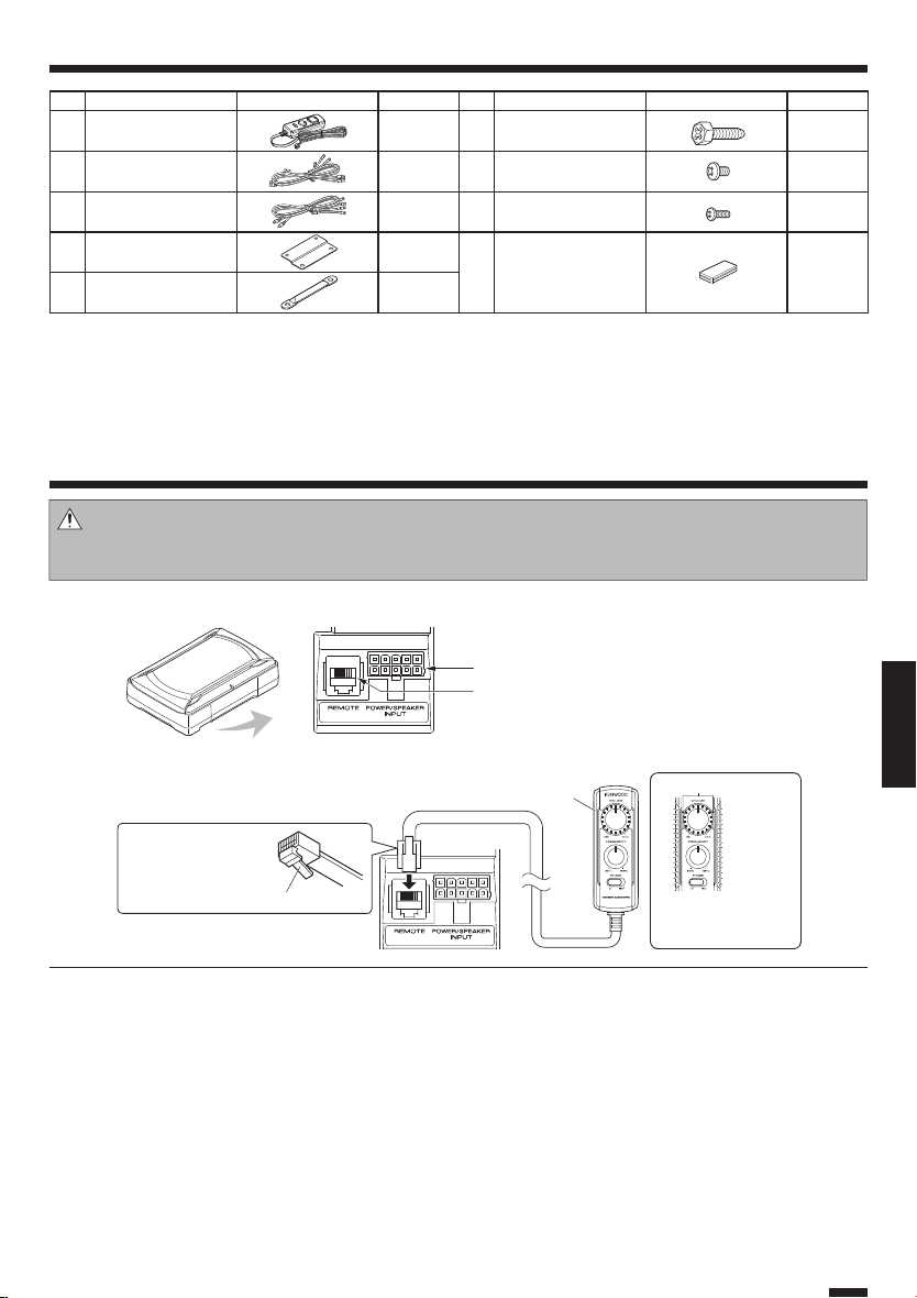
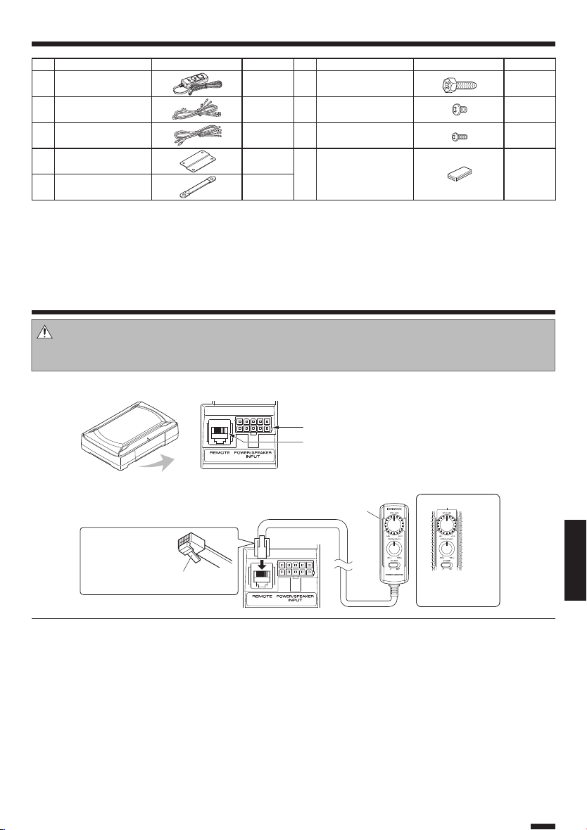
Parts included
No. Part Name Outside Shape Quantity No. Part Name Outside Shape Quantity
Remote control
1
(5 m / 16 ft)
10-pin connec tor cord
2
(5 m / 16 ft)
Speaker cord
3
(4.3 m/ 14 ft)
Fixture A 2
4
Fixture B 1
5
1
1
1
Tapping screw
6
(ø 5 × 16 mm)
Machine screw
7
(M4 × 5 mm)
Machine screw
8
(M3 × 8 mm)
Hook-and-loop fastener
(Double-sid e adhesive/
9
for Remote control)
4
4
2
1
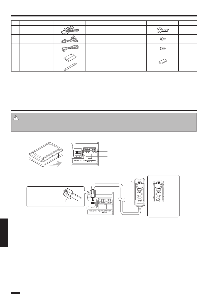
Connection
Caution:
Before wiring, be sure to remove the wire from the negative terminal of the battery. After completing all wiring, check the
correct wirings again. After checking, connect the wire from the negative terminal of the battery.
Terminals of Subwoofer
■
POWER/SPEAKER I NPUT terminal
REMOTE terminal
Connecting the remote control unit
■
Remote control
1
Connect with the l ock
part of remote co ntrol
jack facing down.
Lock part
Notes:
• Be sure to connect the supplied remote control unit.
• If the cord is not connected properly, the illumination on the remote control unit do not light up.
• Do not insert the remote control connector upside down or forcibly. Otherwise, malfunction may result.
Lights in blue.
When the power turns
ON, the illumination
lights.
English
ENGLISH
3
Page 4
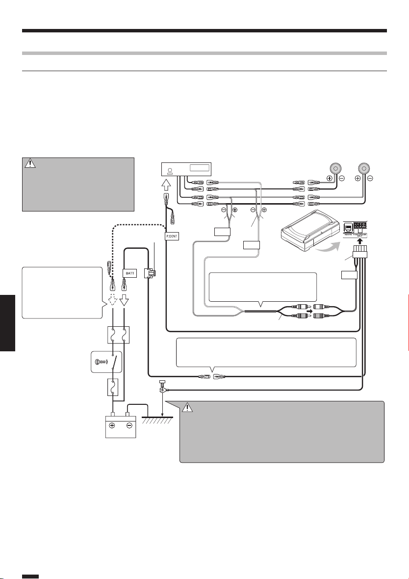
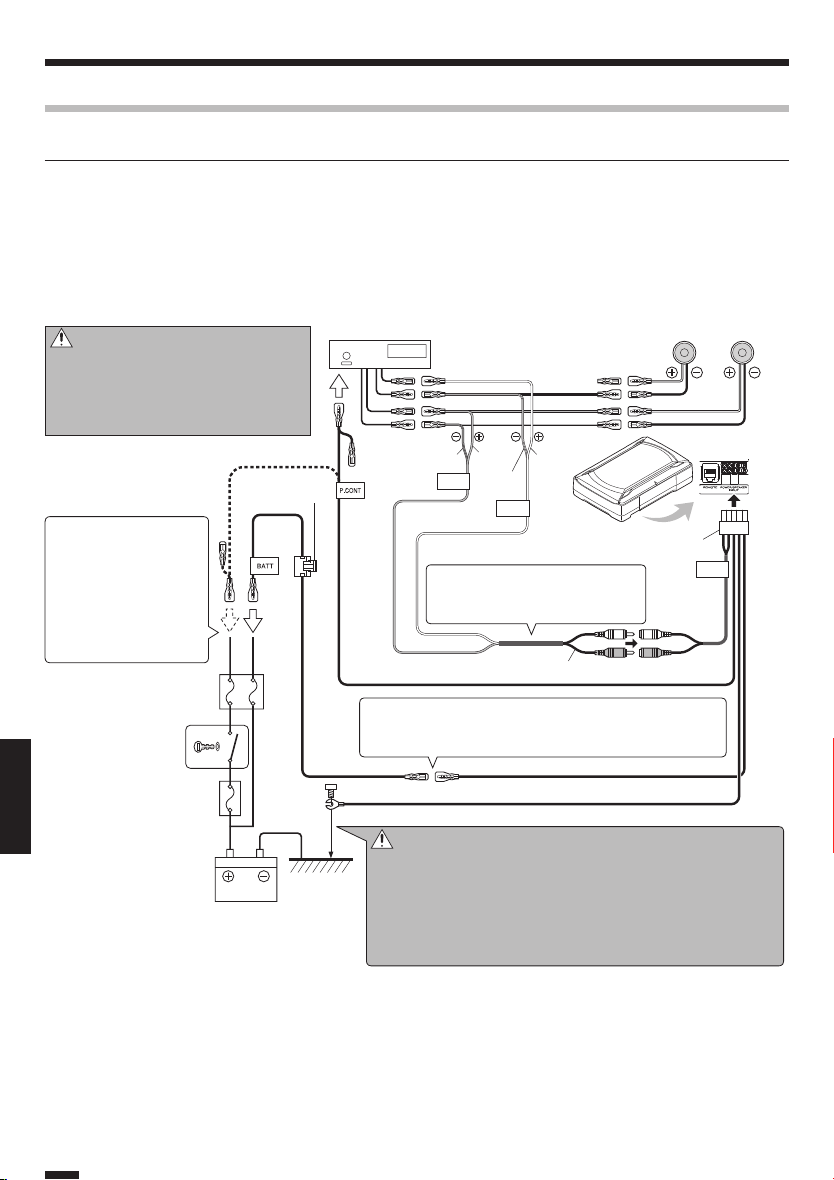
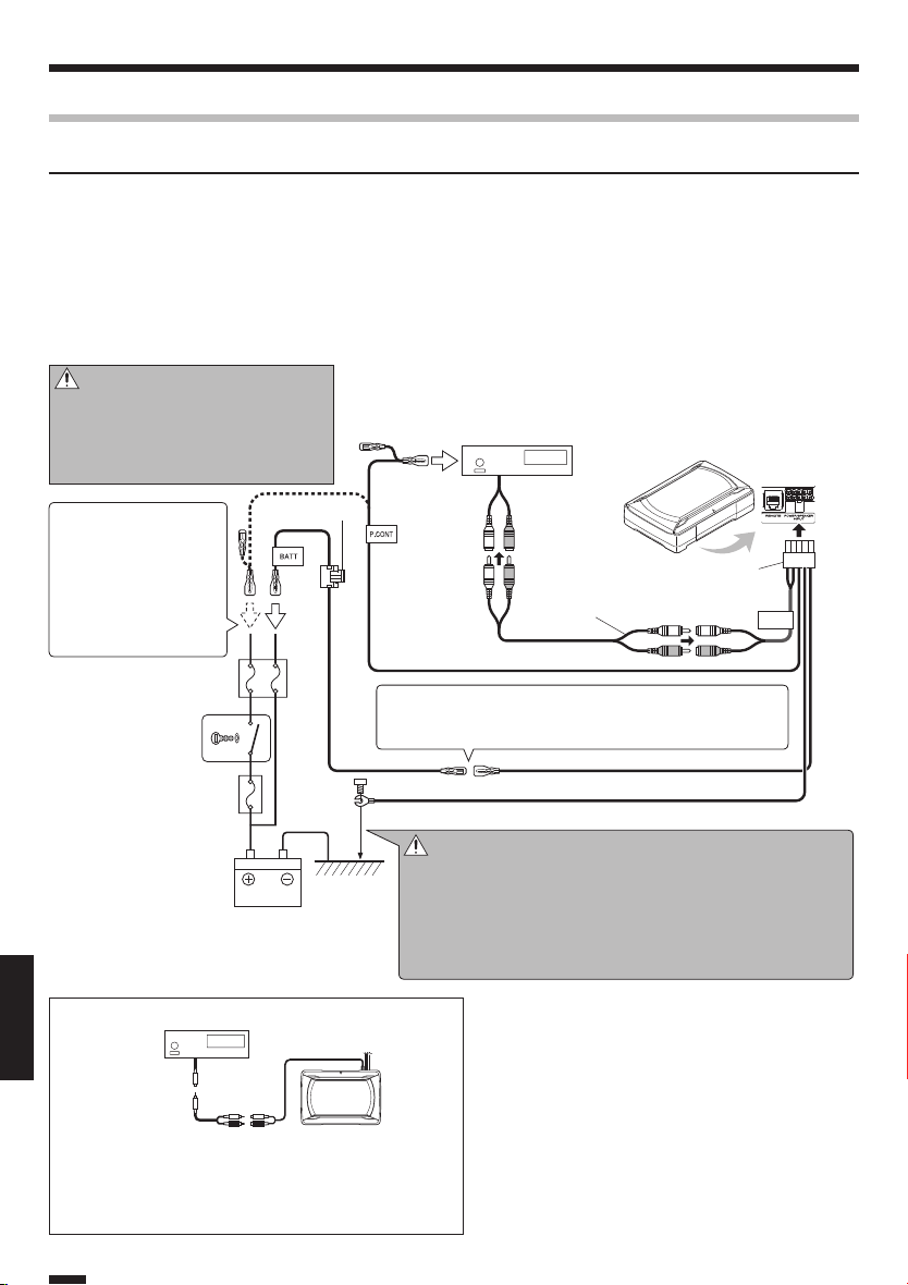
Connection
Speaker input connection
Connect the subwoofer to the front speaker or rear speaker output cords of the center unit.
Notes:
• Read the instruction manuals for the connected components such as the center unit as well as this instruction manual.
• When the center unit incorporates a DSP, do not connect to the rear output, as the low-frequency reproduction effect may
be attenuated due to the DSP effect.
Examples
■
The followi ng shows a typical conne ction for effec tive car stereo enjoy ment. Connect your s ystem by referring to th e example.
Fuse 10A
Center unit
White
GrayGray/Black
SP.R
White/
INPUT
Black
SP.L
INPUT
10-pin connec tor cord
2
Do not bend the vinyl-coated section of the speaker cord. Otherwise,
malfunction may result.
Speaker cord
Blue/White
If buzzing noise is heard from the speakers when the engine
is running, attach a line noise filter (commercially available) to
the power lead.
Yel low Yel low
Black
3
Caution:
Do not distribute the cords in the
paths where they may be caught by
a vehicle part or damaged. Otherwise, an electric shock or a fire due to
short-circuiting may result.
If there is no power control terminal in the center
unit , co nn ect the bl ue /
white wire to the accessory line (ignition key switch
ACC position line).
ENGLISH
Car fuse box
Ignition key
switch
Car fuse box
(Main fuse)
Front or rear speaker
Left Right
KSC-SW11
LINE IN
※
Battery
English
4
Caution:
GND
※
Connect the black lead wire ground terminal directly with a screw
to an unpainted metal part of the vehicle. Turning the power ON
without connecting this terminal is linked to damage of the stereo
system. Be sure to connect it.
Also, painted metal panels etc., are not grounded and will not
function correctly. Be careful.
Page 5
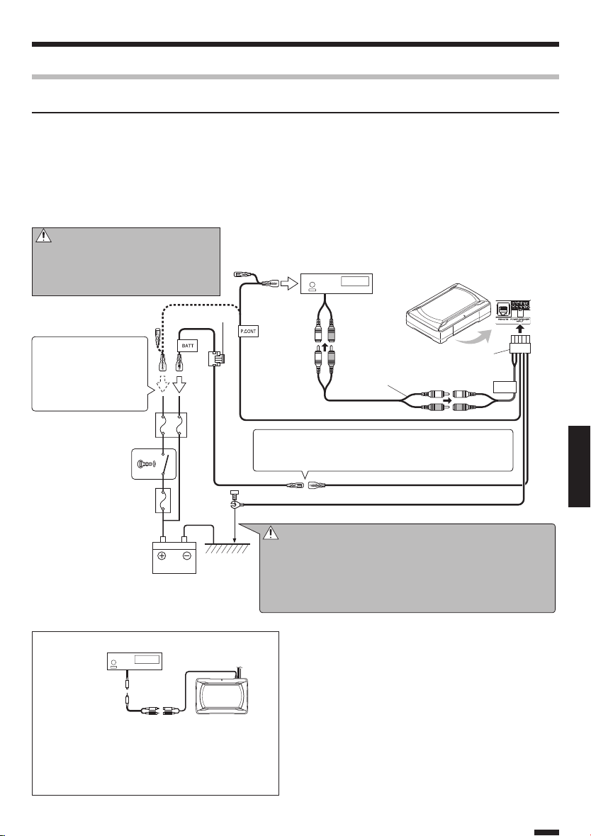
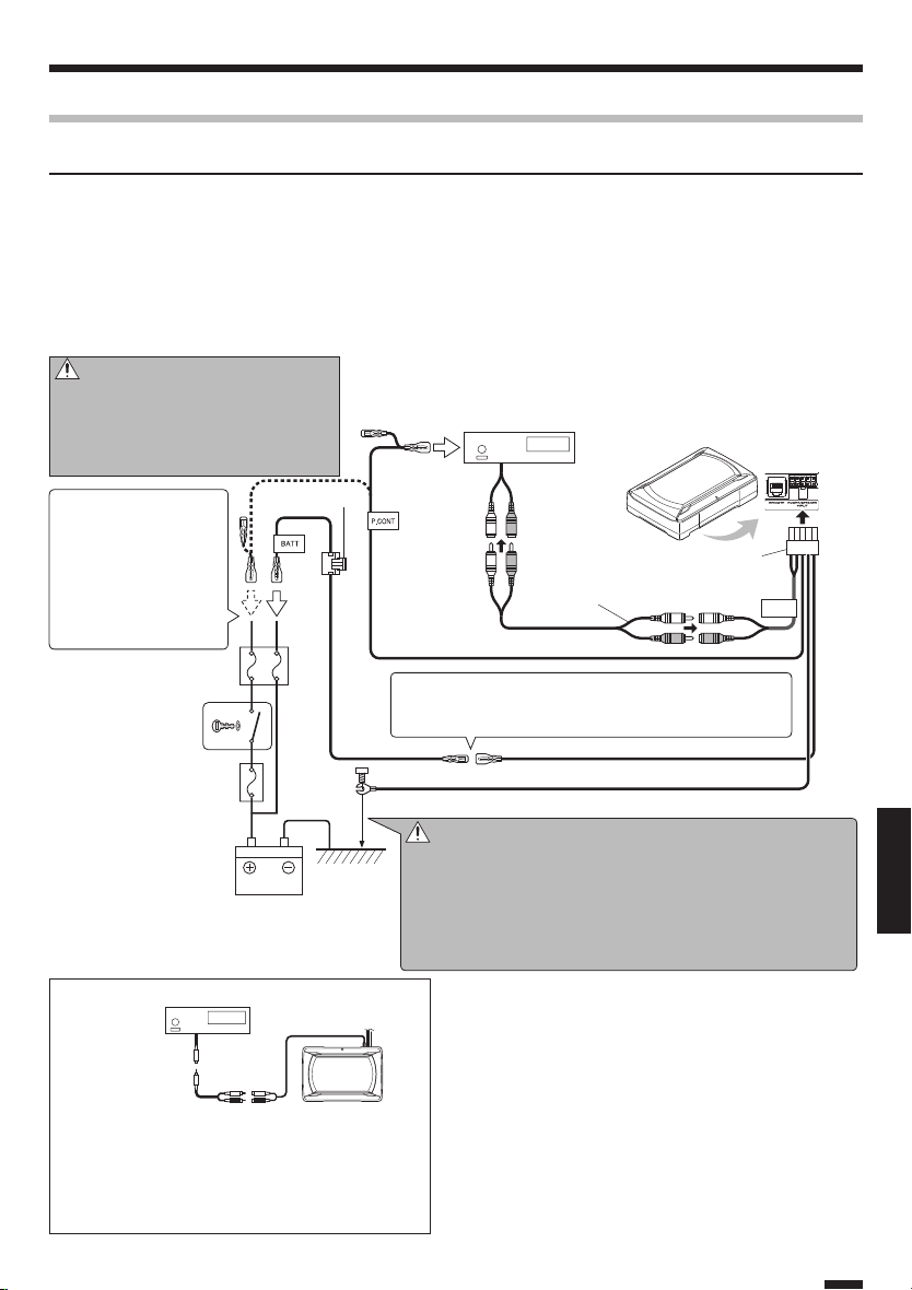
RCA input connection
Connect the subwoofer to the subwoofer output (non-fader output) or the RCA jacks for the front output of the
center unit.
Notes:
• Read the instruction manuals for the connected components such as the center unit as well as this instruction manual.
• Please purchase an RCA cord that is commercially available separately.
• When the center unit incorporates a DSP, connect the subwoofer to the subwoofer output (non-fader output) or to the RCA
jacks for the front output. Do not connect to the RCA jacks for the rear output, as the low-frequency reproduction ef fect may
be attenuated due to the DSP effect.
Examples
■
The followi ng shows a typical conne ction for effec tive car stereo enjoy ment. Connect your s ystem by referring to th e example.
Caution:
Do not distribute the cords in the paths
where they may be caught by a vehicle part
or damaged. Otherwise, an electric shock or
a fire due to short-circuiting may result.
Fuse 10A
If there is no power control terminal in the center
unit , co nn ect the bl ue /
white wire to the accessory line (ignition key switch
ACC position line).
Car fuse box
Ignition key
switch
Car fuse box
(Main fuse)
Battery
Center unit
Center unit
(SUB WOOFER OUT,
Non-fader output)
10-pin connec tor cord
2
RCA cord
(Commercially available parts)
Blue/White
If buzzing noise is heard from the speakers when the engine
is running, attach a line noise filter (commercially available) to
the power lead.
Yel low Yel low
Black
※
Caution:
GND
※
Connect the black lead wire ground terminal directly with a screw
to an unpainted metal part of the vehicle. Turning the power ON
without connecting this terminal is linked to damage of the stereo
system. Be sure to connect it.
Also, painted metal panels etc., are not grounded and will not
function correctly. Be careful.
KSC-SW11
LINE IN
ENGLISH
RCA cord
(Comme rcially
available parts)
KSC-SW11
When the center unit output is a single RCA jack, use
an RCA cord that converts the output into the two RCA
jack s as shown ab ove. T he subwoofer output will be
halved if the conversion cord is not used.
English
5
Page 6
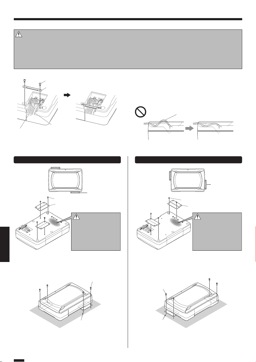
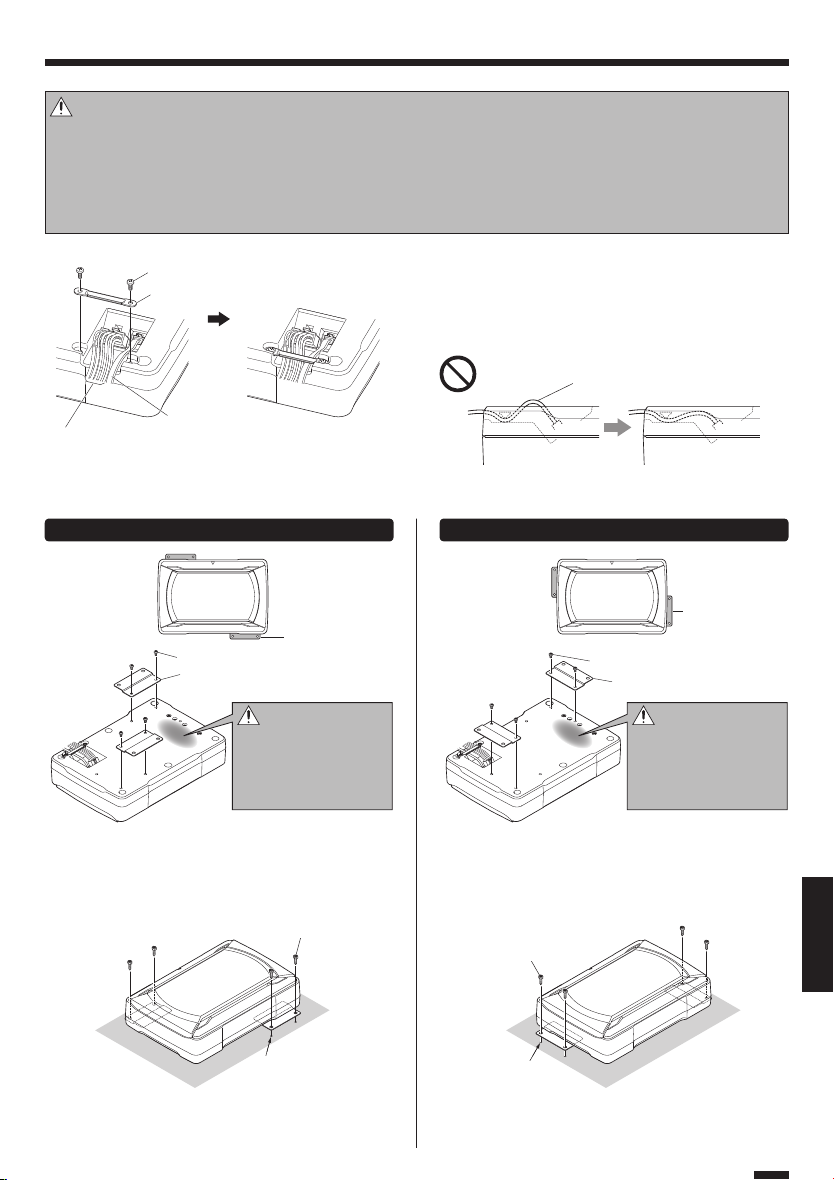
Installation
Before fixing the speaker in its position, be sure to check the sound while it is connec ted preliminary.
Caution:
When making a hole under a seat, inside the trunk, or somewhere else in the vehicle, check that there is nothing hazardous on
•
the opposite side such as a gasoline tank, brake pipe; or wiring harness, and be careful not to cause scratches or other damage.
• Install in a location that does not come in the way of driving, getting in or out of the vehicle and movement inside the vehicle compartment.
• Fix the product firmly so that it will not be moved by vibrations or impacts during driving.
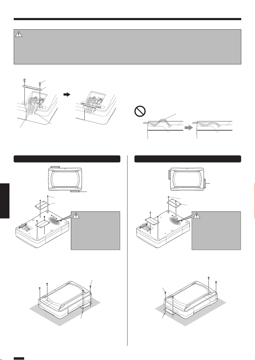
Fixing the cord in place
■
Machine screw x 2
8
Fixture B
5
Connec t the 10-pin connector cord 2 and rem ote
control 1 to the speaker unit.
Fix the cords to the speaker unit with fixture B
fix in place with the machine screws 8.
5
and
Fix the cord so that it will not
protrude from the side of the
speaker unit.
10-pin connec tor cord
2
Fixing the subwoofer
■
1
Prohibition!
Remote control
The subwoofer can be fixed in two ways. Select the optimum attaching position of fixture A 4 according to the subwoofer
installation location.
Fixing method A Fixing method B
Fixture A
4
Fixture A
11
Machine screw x 4
7
Fixture A x 2
4
ENGLISH
Attach the fixtures A 4 to the speaker unit securely
using the machine screws 7. Be careful so that the
connected cords do not get in between the speaker
unit and fix tures A 4.
22
4
Caution:
This portion becomes
slightly hotter than other portions because it
functions as the radiator
of the heat generated by
the amplifier.
Tapping screw x 4
6
Machine screw x 4
7
Fixture A x 2
4
Caution:
This portion becomes
slightly hotter than other portions because it
functions as the radiator
of the heat generated by
the amplifier.
Attach the fixtures A 4 to the speaker unit securely
using the machine screws 7. Be careful so that the
connected cords do not get in between the speaker
unit and fix tures A 4.
Tapping screw x 4
6
Drill four pilot holes for
ø 3.6 mm screws.
Drill the pilot holes for ø 3.6 mm screws on the sheet
metal section of the vehicle , and attach the speaker
unit to the vehicle using the tapping screws 6.
English
6
Drill four pilot holes for
ø 3.6 mm screws.
Drill the pilot holes for ø 3.6 mm screws on the sheet
metal section of the vehicle , and attach the speaker
unit to the vehicle using the tapping screws 6.
Page 7
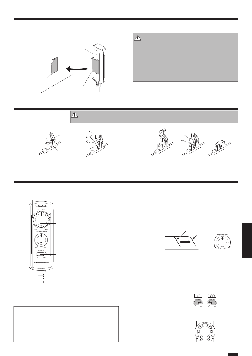
Installing the remote control unit
■
Install the remote control unit on the vehicle by the
provided hook-and-loop fastener.
Vehic le
Hook-and-loop
9
fastener
(Harder surface)
Remote control
1
(Rear panel)
Hook-and-loop
9
fastener
(Softer sur face)
Fuse exchange
Exchange with the specified capacit y fuse.
Removal
■
Fuse
Open the cover.
1
Grasp the fuse and pull up.
2
Caution:
Cover
Fuse ho lder
Be sure to replace with same capacity (amperage) as displayed on the fuse. This product is 10A.
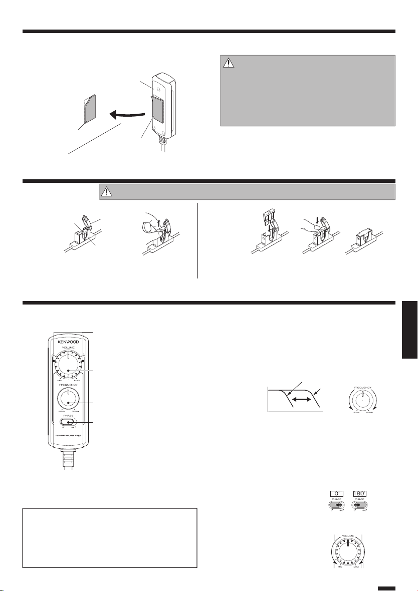
Operation
Name of each part (Remote control )
■
Illumination
When the power turns ON , the
illumination lights.
VOLUME control knob
(Input sensitivit y control knob)
FREQUENCY control k nob
(Cut-off frequ ency control knob)
PHASE switch
(Phase select switch)
Caution:
Install the remote control unit in a position that does not
come in the way of driving operations.
Avoid installing it in a place subject to direct sunlight or
direct hot wind from the heater. Otherwise, the product
may be degraded and a fire hazard may result.
Remove dirt from the installation position before attaching the hook-and-loop fastener.
Insertion
■
Replacement
fuse 10 A
Insert the fuse gently into the fuse holder and push
1
in all the way with your finger.
Close the cover.
2
Adjusting the sound
■
A
0
1
(Remote control operation)
Turn the FREQUENCY control knob to adjust the
1
cut-off frequency (frequencies higher than this
frequency are cut off ).
Turn t he FREQUE NC Y co ntrol knob to adj us t the balance
between the bass from the rear speakers and the bass from this
unit as desired.
Sound pressure
level
Adjust the low frequency phase.
2
The low frequency tone may be variable depending on the position of the unit, its orientation or the turn- over frequency. This
can be adjusted by changing the position of the PHASE switch.
Set this switch to either position according to your liking.
[0°] indicates the normal phase and [180°] means the reverse
phase.
50 Hz
125 Hz
Low High
Frequ ency
Low High
ENGLISH
The sound is output even when the remote control unit
is not connected, but the operations described in this
section are not available.
In this case, the volume, cut-off frequency and phase
are set to the predetermined default conditions, with
which the cut-o frequency is 125 Hz and the phase is
0º (positive).
Turn the VOLUME control knob to adjust the low
3
frequencies to the desired level.
To decrease
volume
To increase
volume
English
7
Page 8
Troubleshooting guide
Often, what ap pears to be a malfunction is due to user error. Before calling for service, please consult the following table.
Problem Cause Remedy
Power cannot be
turned on (illumination does not light).
No sound
Sound is sma ll.
Sound qual ity is bad
(sound is dist orted).
Sound is unnatural.
ENGLISH
Remo te c on trol do es
not work.
The illuminations on
the remote control
unit do not light.
• The fuse is blown. • Check the (+)/(-) polarity of the power cord and
• The power supply pin (yellow) of the 10-pin connection cord is not connected.
• The power control pin (blue/white) of the 10-pin
connectio n cord is not connected.
• The grounding pin (black) of the 10-pin connection cord is not connec ted.
• The 10-pin connector is not plugged in completely.
• The negative (-) cable of the car batter y is disconnected.
• The attenuator of the center unit is set to ON. • Switch the attenuator OFF.
• The VOLUME control is set to the MIN position. • Incr ease the volume to an optimu m leve l (on
• The speaker cords are connected improperly. • Connect the cords correctly by referring to the
• Connection terminals are connected improperly. • Insert the connectors or jacks all the way in to
• The input level is set to low. • Turn the VOLUME control knob and set the in-
• Connection terminals are connec ted improperly. • Plug the cord into the REMOTE terminal.
• The input level is set to high. • Turn the VOLUME control knob and set the in-
• The speaker cords are connected with incorrect
positive (+)/negative (-) polarity.
• The grounding pin (black) of the 10-pin connection cord is poorly contacted.
• The remote control cord is unplugged. • Plug the cord into the REMOTE terminal.
tha t the cords a re not shor ted, t he n replace
with a fuse with the rated capacity.
• Re-connec t the cords correctly by referring to
the connection e xample (on page 4, 5).
• Connec t the cord correctly by referring to the
connection e xample (on page 4, 5).
• Attach the grounding terminal to the metallic
section of the vehicle (not a coated surface) by
tightly screwing it.
• Insert the connec tor all the way in.
• Check the connections of all cords, then connect the (-) cable to the bat tery.
• Check the connections of all cords, then connect the (-) cable to the bat tery.
page 7).
connection example (on page 4).
the terminals.
put level to an optimum leve l.
• Check that the RCA cord is connected prop erly.
put level to an optimum leve l.
• Connect the cords correctly by referring to the
connection e xample (on page 4, 5).
• Attach the grounding terminal to the metallic
section of the vehicle (not a coated surface) by
tightly screwing it.
• Insert the connector all the way in.
Specifications
The following ratings and design are subject to change without notice.
Maximum o utput ..............................................................150 W
Frequenc y response ........................................... 35 Hz - 150 Hz
Cut-off f requency ............................................... 50 Hz - 125 Hz
Phase ................................................................................0˚, 180˚
Input sensitivity/impedance
LINE IN .............................................................. 50 mV / 22 kΩ
English
8
Power ......................... DC 14.4 V (Operating rang e 11 V - 16 V)
Maximum c urrent consumptio n ...................................... 8.5 A
Fuse capacit y ........................................................................10 A
Sensiti vity ............................................................110 dB (In car)
Exter nal size ......................................Width : 280 mm (11")
Height : 70 mm (2-3/4")
Depth : 190 mm (7-1/2")
Weight (net) .......................................................... 2.8kg (6. 2 Ib)
Page 9

English
ENGLISH
9
Page 10
CONSIGNES DE SÉCURITÉ IMPORTANTES
Attention : Lire attentivement cette page pour garantir une exploitation sans danger.
AVERTISSEMENT AVERTISSEMENT
• Avant d'effectuer le montage ou le câblage, etc., assurez-vous de débrancher la borne négative de la batterie.
(Dans le cas contraire, vous risquez de déclencher un
court-circuit ou un incendie)
• Si vous devez rallonger les câbles d’allumage, de batterie
et de masse, utilisez des câbles pour véhicules automobiles ou des câbles ayant au moins une section de 0,75
2
(AWG 18) de façon à éviter un endommagement du
mm
câble ou de son isolant.
• Pour éviter tout court-circuit, n’introduisez jamais un objet métallique (pièces de monnaie, outils) dans un hautparleur.
• Dans le c as où l’appareil produit de la fumé e ou une
odeur anormale, couper immédiatement l’alimentation.
Contacter ensuite votre concessionnaire ou centre de service plus proche le plus rapidement possible.
COUPER L’ALIMENTATION!
• Raccordez le haut-parleur à 12 V CC, mise à la terre négative.
• Ne pas essayer de démonter ni de modifier l'appareil
car ceci risque de provoquer un risque d’incendie ou un
fonctionnement incorrect.
• Ap rès avoir rentré l’appareil du sa c de p olyé thylène,
bien placer ce dernier hors de la portée des enfants. S’ils
jouent avec ce sac, un risque d’étouffement est possible.
ATTENTION ATTE NTION
• L’ins tallation et le câblage de ce produit exig ent des
connaissances et une expérience professionnelles. Pour
des raisons de sécurité, l’installation et le câblage doivent
être effectués par le revendeur de ce produit ou par un
spécialiste.
• N’installez pas le haut-parleur dans un endroit directement exposé au soleil ou à une humidité ou chaleur excessives.
• Ne pas installer les haut-parieurs dans des endroits où ils
peuvent être exposés à de l’eau ou à l’humidité.
• Ne pas installer les haut-parleurs dans de endroits instables ou exposés à de la poussière.
• Si le fusible grille, assurez-vous de le remplacer, après
avoir vérifié que le câblage n’est pas en court-circuit, par
un fusible du calibre spécifié (ampérage) sur le boîtier.
FRANÇAIS
(L’utilisation de fusible de calibre supérieur peut causer un
incendie)
Vérifiez L'affichage !
Pour le remplacement de fusible, consultez le manuel
d’utilisation du véhicule.
• Avant de remplacer le fusible et pour éviter tout court-circuit, débranchez le faisceau.
• N’utilisez ni essence, ni pétrole ni aucun solvant pour nettoyer le haut parleur. Utilisez un chiffon doux et sec.
• Re liez sé parément le s co rd ons de liaiso n des hautparleurs aux bornes convenables. Une liaison commune
du cordon relié à la borne négative, ou la mise à la masse
de la carrosserie de ces cordons peuvent entraîner une
anomalie de fonctionnement.
• Avant de percer un trou sous un siège, dans le coffre et,
d’une manière générale, en n’importe quel point du véhicule, assurez-vous que vous pouvez le faire sans danger
et que votre intervention ne conduira pas à l’endommagement du réservoir de carburant, d’une canalisation de
frein ou d’un faisceau électrique; veillez également à ne
pas effectuer de rayures ou d’autres dommages inutiles.
• Pour le raccordement à la masse, ne pas fixer le fil à un
airbag, au système de direction, à une ligne du système
de freinage ou à tout autre boulon ou écrou critique en
terme de sécurité. (Risque d’accident).
• Pour l’installation, choisissez un emplacement qui ne présente aucune gêne pour la conduite du véhicule ou un
danger pour les passagers lors de freinages soudains, etc.
(Risque de blessure ou d’accident)
• Après installation assurez-vous que les équipements électriques tels que les feux stop, les feux clignotants et les
essuie glace fonctionnent toujours normalement.
• Le conducteur devrait toujours arrêter le véhicule en lieu
sûr avant d’effectuer l’opération suivante.
– Utiliser la télécommande
• Ce produit ne doit être utilisé que dans une installation
embarquée.
Déclaration de conformité se rapportant à la directive EMC 2014/30/UE
Déclaration de conformité se rappor-
Fabricant:
JVC KENWOOD Corporation
3-12 Moriya-cho, Kanagawa-ku, Yokohama-shi,
Kanagawa, 221-0022, JAPON
Représentant dans l’UE:
JVCKENWOOD Europe B.V.
Amsterdamseweg 37, 1422 AC Uithoorn, PAYS-BAS
Information sur l’élimination des anciens équipements électriques et électroniques (applicable
dans les pays qui ont adopté des systèmes de collecte sélective)
Contactez vos autorités locales pour connître le site
de recyclage le plus proche. Un recyclage adapté et
l’élimination des déchets aideront à conserver les ressources et à nous préserver des leurs effets nocifs sur
notre santé et sur l’environnement.
tant à la directive RoHS 2011/65/UE
Les produits sur lesquels le pictogramme
(poubelle barrée) est apposé ne peuvent pas
être éliminés comme ordures ménagères.
Les anciens équipements électriques et
électroniques doivent être recyclés sur des
sites capables de traiter ces produits et leurs
déchets.
10
Français
Page 11
Fournitures
Nº
Désignation des pièces
Télécommande
1
(5 m)
Cordon de connection à
2
10 broches (5 m)
Cordon d’enceinte
3
(4,3 m)
Support A 2
4
Support B 1
5
Forme extérieure Quantité Nº
1
1
1
Désignation des pièces
Vis auto taraudeuse
6
(ø 5 × 16 mm)
Vis à métaux
7
(M4 × 5 mm)
Vis à métaux
8
(M3 × 8 mm)
Bandes autoagrippantes
(Ruban adhésif double
9
face/Pour Télécommande)
Forme extérieure Quantité
4
4
2
1
Connexions
Attention:
Avant d’effectuer le câblage, détachez le câble de la borne négative de la batterie. Lorsque le câblage est terminé, vérifiez si
les câbles sont tous bien raccordés. À ce moment seulement, rebranchez le câble sur la borne négative de la batterie.
Bornes du caisson d’extrême grave
■
Borne POWER /SPEAKER INPUT
Borne REMOTE
Raccordement de la télécommande
■
Télécommande
1
Raccordez la section
verrou de la prise de
télécommande vers le
bas.
Remarques:
• Veillez à raccorder la télécommande fournie.
• Si le cordon n’est pas raccordé correctement, l’éclairage de la télécommande ne s’allume pas.
• N’insérez pas le connecteur de télécommande à l’envers et ne forcez pas lorsque vous l’insérez. Cela peut provoquer une
panne.
Section ver rou
de la prise
S’allume en bleu.
À la mise sous
tension, l’éclairage
s’allume.
Français
FRANÇAIS
11
Page 12
Connexions
Raccordement aux entrées des haut-parleurs
Raccordez le caisson d’extrême grave aux cordons de sortie de haut-parleur avant ou de haut-parleur arrière de
l’unité centrale.
Remarques:
• Lisez les modes d’emploi des composants raccordés, par exemple de l’unité centrale ainsi que ce mode d’emploi.
• Lorsque le haut-parleur central comprend un DSP, ne raccordez pas la sortie arrière, car l’effet de restitution des basses fréquences peut être atténué par l’effet DSP.
Exemples
■
L’exemple suivant montre le type de raccordement usuellement effectué pour un appareil stéréo embarqué. Suivez cet
exemple p our raccorder votre pr opre appareil.
Attention:
Ne disposez pas les cordons de sorte qu’ils
risquent d’être pris par une pièce du véhicule ou endommagés. Sinon, cela peut provoquer un choc électrique ou un incendie à
cause d’un court-circuit.
Si l'unité centrale ne
comporte pas de borne
de commande d'alimentation, connectez
les fils bleu et blanc à la
ligne pour accessoires
(alimentée lorsque la clef
de contact est placée sur
ACC).
Boîte de fusible
Commutateur à clef
Boîte de fusible
(Fusible principal)
FRANÇAIS
Batterie
Fusible 10A
※
Unité centrale
Blanc
GrisGris/Noir
SP.R
Blanc/
INPUT
Noir
SP.L
INPUT
Ne pli ez pas la p ar t ie gainée d u
cordon de haut-parleur. Cela peut
provoquer une panne.
Cordon d’enceinte
Bleu/Blanc
Si un ronronnement se fait entendre par les haut-parleurs
lorsque le moteur tourne, monter un filtre antiparasite de
ligne (vendu séparément) sur le conducteur d'alimentation.
Jaune Jaune
Noir
Attention:
GND
※
Connectez le fil de masse noir avec une vis directement sur une
partie métallique non peinte du véhicule. Toute mise sous tension
sans connecter ce fil de masse risque d'endommager le système
stéréo. N'oubliez surtout pas de le connecter. La peinture, etc.,
risque de ne pas produire une connexion appropriée à la masse
et d'empêcher le fonctionnement correct de l'appareil. Prenez les
précautions appropriées.
3
Haut-parleurs avant ou arrière
Gauche Droite
Cordon de connection
2
à 10 broches
KSC-SW11
LINE IN
12
Français
Page 13
Raccordement aux entrées RCA
Raccordez le caisson d’extrême grave à la sortie d’extrême grave (sortie non atténuée) ou aux prises RCA pour la
sortie avant de l’unité centrale.
Remarques:
• Lisez les modes d’emploi des composants raccordés, par exemple de l’unité centrale, ainsi que ce mode d’emploi.
• Veuillez vous procurer un cordon RCA en vente dans le commerce.
• Si l’unité centrale contient un DSP, raccordez le caisson d’extrême grave à la sortie d’extrême grave (sortie non atténuée) ou
aux prises RCA de la sortie avant. Ne raccordez pas les prises RCA de la sortie arrière, parce que l’effet basse fréquence peut
être atténué par l’effet DSP.
Exemples
■
L’exemple suivant montre le type de raccordement usuellement effectué pour un appareil stéréo embarqué. Suivez cet
exemple p our raccorder votre pr opre appareil.
Attention:
Ne disposez pas les cordons de sorte qu’ils
risquent d’être pris par une pièce du véhicule ou endommagés. Sinon, cela peut provoquer un choc électrique ou un incendie à
cause d’un court-circuit.
Unité centrale
(SUB WOOFER OUT,
Sortie non at ténuée)
KSC-SW11
Batterie
Fusible 10A
※
KSC-SW11
Si un ronronnement se fait entendre par les haut-parleurs
lorsque le moteur tourne, monter un filtre antiparasite de
ligne (vendu séparément) sur le conducteur d'alimentation.
GND
Si l'unité centrale ne
comporte pas de borne
de commande d'alimentation, connectez
les fils bleu et blanc à la
ligne pour accessoires
(alimentée lorsque la clef
de contact est placée sur
ACC).
Boîte de fusible
Commutateur à clef
Boîte de fusible
(Fusible principal)
Unité centrale
Câble RCA
(disponible dans
le commerce)
Lorsque la sortie de l’unité centrale est une prise RCA,
utilisez un cordon RCA divisant la sortie sur deux prises
RCA, comme indiqué ci-dessus. Si le cordon de conversion n’est pas utilisé, le signal de sortie de l’extrême
grave sera tronqué de moitié.
Cordon de connection
2
à 10 broches
LINE IN
Bleu/Blanc
Jaune Jaune
Noir
Câble RCA
(disponible dans le commerce)
Attention:
※
Connectez le fil de masse noir avec une vis directement sur une
partie métallique non peinte du véhicule. Toute mise sous tension
sans connecter ce fil de masse risque d'endommager le système
stéréo. N'oubliez surtout pas de le connecter. La peinture, etc.,
risque de ne pas produire une connexion appropriée à la masse
et d'empêcher le fonctionnement correct de l'appareil. Prenez les
précautions appropriées.
FRANÇAIS
Français
13
Page 14
Installation
Avant de fixer le haut-parleur à endroit donné, faire une essai de raccordem ent pour contrôler le son.
Attention:
•
Avant de percer un trou sous un siège, dans le coffre et, d’une manière générale, en n’importe quel point du véhicule, assurez-vous
que vous pouvez le faire sans danger et que votre intervention ne conduira pas à l’endommagement du réservoir de carburant, d’une
canalisation de frein ou d’un faisceau électrique; veillez également à ne pas effectuer de rayures ou d’autres dommages inutiles.
• Choisissez un emplacement qui ne risque pas de gêner la conduite, l’entrée ou la sortie du véhicule et les mouvements à
l’intérieur du véhicule.
• Fixez bien le produit de sorte que les vibrations ou les chocs dus à la conduite ne risquent pas de le déplacer.
Fixation du cordonFixation du cordon
■
Vis à métaux x 2
8
Support B
5
Raccordez le cordon de connection à 10 broches 2 et
la télécommande 1 au haut-parleur.
Fixez les câbles au haut-parleur avec le support B 5 et
immobilisez-les avec les vis à métaux
.
8
Fixez le cordon de sorte qu’il ne
ressorte pas du côté du hautparleur.
Télécommande
Cordon de connec tion à 10 broches
2
Fixation du caisson d'extrême grave
■
1
Interdiction!
Le caisson d’extrême grave peut être fixé de deux façons. Sélectionnez la position optimale pour la fixation du support A 4
selon l’endroit où le caisson d’extrême grave doit être installé.
Méthode de xation A Méthode de xation B
Support A
4
Support A
11
FRANÇAIS
Accrochez les supports A 4 à l'enceinte fermement à
Vis à métaux x 4
7
Support A x 2
4
l'aide des vis à métaux 7. Faites attention de ne pas
coincer les câbles raccordés entre le haut-parleur et
les supports A 4.
22
4
Attention:
Cette partie devient légèrement plus chaude que
les autres parties parce
qu’elle radie directement
la chaleur générée par
l’amplificateur.
Vis auto taraudeuse x 4
6
Vis à métaux x 4
7
Support A x 2
4
Attention:
Cette partie devient légèrement plus chaude que
les autres parties parce
qu’elle radie directement
la chaleur g énérée par
l’amplificateur.
Accrochez les supports A 4 à l'enceinte fermement à
l'aide des vis à métaux 7. Faites attention de ne pas
coincer les câbles raccordés entre le haut-parleur et
les supports A 4.
Vis auto taraudeuse x 4
6
Percez quatre trous pour vis
de 3,6 mm de diamètre.
Percez des trous de 3,6 mm de diamètre dans le métal de la voiture et fixez le caisson au véhicule à l’aide
de vis auto taraudeuses 6.
Français
14
Percez quatre trous pour
vis de 3,6 mm de diamètre.
Percez des trous de 3,6 mm de diamètre dans le métal de la voiture et fixez le caisson au véhicule à l’aide
de vis auto taraudeuses 6.
Page 15
Installation du boîtier de télécommande
■
Installez le boîtier de télécommande sur le véhicule
avec les bandes autoagrippantes fournies.
Télécommande
1
(Panneau arrière)
Véhic ule
Bandes
9
autoagrippantes
(surface rugueuse)
Bandes
9
autoagrippantes
(surface douce)
Remplacement de fusible
Remplacez le fusible défectueux
par un autre du calibre spécifié.
Retrait
■
1
2
Fusibl e
Support de fusible
Ouvrez le couvercle.
Prenez le fusible et tirez.
Attention: Ne remplacer le fusible que par un autre du même calibre (ampérage) marqué
Couvercle
dessus. 10A dans ce cas.
Fonctionnement
Désignation de chaque pièce (Télécommande)
■
Éclairage
À la mise sous tension, l’éclairage
s’allume.
Commande VOLUME
(Bouton de réglage de la sensibilité
de l’entrée)
Commande FREQUENCY
(Bouton de réglage de la fréquence
de coupure)
Commutateur PHASE
(Commutateur de phase)
Attention:
Installez le boîtier de télécommande dans un endroit tel
qu'il ne gêne en rien la conduite.
Evitez d'installer le boîtier de télécommande dans un
endroit où il serait exposé à la lumière du soleil ou à l'air
chaud du radiateur. Sinon le produit risque de se détériorer et provoquer un incendie.
Nettoyez la surface avant de poser la bande autoagrippante.
Insertion
■
Fusible de
rechange de 10A
Insérez avec précautions le fusible dans son support et
1
appuyez avec le doigt pour qu’il soit introduit à fond.
Fermez le couvercle.
2
Réglage du son
■
A
0
1
(par la télécommande)
Tournez le bouton de réglage FREQUENCY pour
1
régler la fréquence de coupure (les fréquences supérieures à cette fréquence sont coupées).
Tourner le bouton de réglage FREQUENCY pour régler à volonté
la balance entre les basses de haut-parleurs arrière et les basses
de cet appareil.
50 Hz
125 Hz
Niveau de pression
acoustique
Grave Aigu
Fréqu ence
Mettre les basses fréquences en phase.
2
La tonalité des basses fréquences varie en fonction de la position de l'appareil, de son orientation et de la fréquence de transition. Elle est réglable par la position du commutateur PHASE.
Choisir le position de ce commutateur selon son goût.
[0°] indique la phase normale et [180°] indique la phase inversée.
Grave Aigu
FRANÇAIS
Le son est audible même lorsque la télécommande n’est
pas raccordée, mais les opérations décrites dans cette
section ne sont pas disponibles.
Dans ce cas, le volume, la fréquence de coupure et la
phase sont tels que définis par défaut, avec une fréquence de coupure de 125 Hz et une phase de 0° (positive).
Tournez le bouton de réglage VOLUME pour régler
3
les fréquences inférieures au niveau souhaité.
Pour réduire
le volume
Pour augmenter
le volume
Français
15
Page 16
Guide de dépannage
Bien souvent, ce qui semble un mauvais fonc tionnement de l'appareil est dû à une manipulation erronée de l'utilisateur.
Avant de faire appel au réparateur, passer la tableau suivant en revue.
Problème Cause Remède
L'appareil ne peut pas
être mis so us tension
(l'éclairage ne s'allume
pas).
Pas de son
Le son est fai ble.
L a qualité sonore est
insuff isante (le son est
déformé).
Les sons ne sont pas
naturels.
La télécommande ne
fonctionne pas.
FRANÇAIS
L’éclairage sur la télécommande ne s’allume
pas.
• Le fusible est grillé. • Contrôlez les polarités (+) et (-) des cordons et
• La broche d'alimentatio n (jau ne) du câble à 10
broches n'est pas raccordée.
• La broche de commande d'alimentation (bleu/
blanc) du câble à 10 broches n'est pas raccordée.
• La broche de masse (noire) du câble à 10 broches
n'est pas raccordée.
• Le connecteur à 10 broches n'est pas complètement connecté.
• Le câble négatif (-) de la bat terie est débranché. • Vérifiez les raccordements de tous les cordons
• L'atténuateur de l'appareil central est sur ON. • Mettez hors service l'atténuateur.
• La commande VOLUME est sur la position MIN. • Augmentez le niveau de sortie jusqu'à la valeur
• Les cordons de liaison aux haut-parleurs ne sont
pas convenablement raccordés.
• Les bornes ne sont pas convenablement raccordées.
• Le niveau d’entrée est réglé trop bas. • Tournez le bouton de réglage VOLUME et réglez
• Les bornes ne sont pas convenablement raccordées.
• Le niveau d’entrée est réglé trop haut. • Tournez le bouton de réglage VOLUME et réglez
• Les cordons de liaison aux haut-parleurs sont incorrectement reliés du point de vue des polarités
positive (+) et négative (-).
• La broche de masse (noire) du câble à 10 broches
n'établit pas un bon contac t.
• Le câble de la télécommande est débranché. • Branchez le cordon sur la borne REMOTE.
assurez-vous que les cordon s ne sont pas en
court-circuit, puis remplacez le fusible par un
fusible du même calibre.
• Rebranchez les cordons comme il convient en
vous reportant à l'exemple de connexion (page
12, 13).
• Branches le cordon comme il convient en vous
reportant à l'exemple de conne xion (page 12,
13).
• Fixez la borne de masse à une partie métallique
du véhicule (une partie non peinte) par un serrage soigneux.
• Introduisez à fond le connecteur.
• Vérifiez les raccordements de tous les cordons
puis reliez le câble (-) à la bat terie.
puis reliez le câble (-) à la bat terie.
optimale (page 15).
• Branchez l es c or do ns c om me i l co nv ie nt e n
vous reportant à l'exemple de connexion (page
12).
• Introduisez à fond les co nnecteurs et les prises.
le niveau d’entrée à un niveau optimal.
• Branchez le cordon sur la borne REMOTE .
• Assurez-vous que le cordon RCA est raccordé
correcteme nt.
le niveau d’entrée à un niveau optimal.
• Bra nc hez les cordons comme il convient en
vous reportant à l'exemple de connexion (page
12, 13).
• Fixez la borne de masse à une partie métallique
du véhicule (une partie non peinte) par un serrage soigneux.
• Introduisez à fond le connecteur.
Caractéristiques
La conception et les c aractéristiques suivantes peuvent être modifiées sans préavis.
Puissance m aximum .........................................................150 W
Réponse e n fréquence ........................................ 35 Hz - 150 Hz
Coupure de fr équence ........................................ 50 Hz - 125 Hz
Phase ................................................................................0˚, 180˚
Sensibilité/impédance d'entrée
LINE IN .............................................................. 50 mV / 22 kΩ
Français
16
Alimentat ion ...............................................................DC 14,4 V
Consommat ion maximale ................................................. 8,5 A
Calibre du f usible .................................................................10 A
Sensibil ité ........................................110 dB (Dans une voitur e)
Dimensi ons hors tout ...........................Lar geur: 280 mm
Hauteur: 70 mm
Profondeur: 190 mm
Poids (net) ..........................................................................2,8 kg
(Interva lle de fonctionne ment 11 V à 16 V)
Page 17
WICHTIGE SICHERHEITSINSTRUKTIONEN
Achtung: Lesen Sie diese Seite sorgfältig durch, um einen sicheren Betrieb zu gewährleisten.
WARNUNG WARNUNG
• Trennen Sie vor der Installation oder Verdrahtung etc.
unbedingt den Draht von der Minus-Klemme der Batterie
ab.
(Andernfalls könnte ein elektrischer Schlag oder Brand die
Folge sein.)
• Beim Verlängern der Zündschalter-, Batterie- oder Massekabel unbedingt ein für Fahrzeuge vorgesehene Kabel
oder Leitungen gleichwertiger Qualität verwende, die
einen Mindestquerschnitt von 0,75 mm
sen; dies verhindert einen vorzeitgen Verschleiß und eine
Beschädigung der Schutzhüllen.
• Um einen Kurzschluß zu vermeiden, niemals Metallgegenstände (wie zum Beispiel Münzen oder Werkzeuge
aus Metall) im Innern des Lautsprechers liegenlassen.
• Dei Brandgeruch oder Rauch muß die Spannungsversorgung sofort ausgeschaltet werden, Wenden Sie sich dann
so bald wie möglich an Ihren Fachhändler oder eine Kundendienststelle.
AUSSCHALTEN!
• Schließen Sie den Lautsprecher an Gleichstrom 12 V, negative Masse, an.
• Niemals versuchen, die Lautsprecher zu öffnen oder zu
verändern, weil dadurch Feuergefahr und Fehlfunktionen
hervorgerufen werden können.
• Nach der Entnahme der Lautsprecher aus dem Polyäthylenbeutel muß dieser für Kinder unerreichbar endzorgt
werden. Wenn Kinder mit dem Bauteil spielen, besteht
Erstickungsgefahr.
2
(AWG 18) aufwei-
VORSICHT VORSICHT
• Installation und Verdrahtung des Produk ts erfordern
fachmännische Fähigkeiten und Erfahrung. Um Sicherheit
zu gewährleisten, lassen Sie Installation und Verdrahtung
immer von Ihrem Fachhändler oder einem Spezialisten
ausführen.
• Der Lautsprecher darf nicht an Stellen montiert werden,
die einer direkten Sonnenbestrahlung, übermäßiger Wärme oder starker Luftfeuchtigkeit ausgesetzt sind.
• Die Lautsprecher nicht an stellen einbauen, wo sie Wasser
oder Feuchtigkeit ausgesetzt werden.
• Die Lautsprecher nicht an unstabilen Stellen oder Stellen,
wo sie Staub ausgesetzt sind, einbauen.
• Wenn die Sicherung herausgesprungen ist, überprüfen
Sie zunächst, ob ein Kurzschluss vorliegt. Tauschen Sie die
Sicherung dann gegen eine Sicherung mit der auf dem
Sicherungskasten aufgeführten vorgeschriebenen Kapazität (Amperezahl) aus.
(Die Benutzung anderer als der vorgeschriebenen Siche-
rungen kann einen Brand verursachen.)
Überprüfen Sie das Display!
Beziehen Sie sich bezüglich des Sicherungsaustausches
auf die Betriebsanleitung Ihres Fahrzeuges.
• Um einen Kurzschluß beim Auswechseln der Sicherung
zu vermeiden, ist vor Beginn der Arbeiten das Zuleitungskabel abzuziechen.
• Zur Reinigung des Lautsrecers niemals Benzin, Kerosin
oder ein anderes Lösungsmittel verwenden. Zum Sauberwischen stets einen weichen, trockenen Lappen benutzen.
• Die Lautsprecherkabel nacheinander mit dem entsprechende n Lauts precher stecker verbi nden. Wenn das
Minuskabel des Lautsprechers mit einem anderen Kabel
in Kontakt kommt, oder das Lautsprecherkabel an einem
Metallteil der Fahrzeugkarosserie geerdet wird, hat dies
eine Funktionsstörung des Lautsprechers zur Folge.
• Wenn unter der Sitzbank, im Innern des Kofferraums oder
an einer anderen Stelle des Fahrzeugs eine Kabelöffnung
angebracht werden muß, ist es unbedingt erforderlich,
vorher den umliegenden Bereich zu überprüfen, damit
andere Komponenten, wie zum Beispiel Kraftstofftank,
Bremsleitungen oder Kabelbäume, nicht im Wege sind;
ebenso darauf achten, daß andere Teile nicht verkratzt
oder anderweitig beschädigt werden.
• Der Erdungsdraht darf weder am Airbag, an der Lenkung,
am Bremsleitungssystem noch an einem anderen für die
Sicherheit wichtigen Ort befestigt werden. (Dies könnte
Unfälle verursachen.)
Wählen Sie einen Installationsort, der weder das Fahren
•
des Fahrzeuges beeinträchtigt noch bei plötzlichem Bremsen etc. eine Gefahr für die Mitfahrer darstellt. (Dies könnte
sowohl Verletzungen als auch Unfälle verursachen.)
• Nach dem Einbau der Einheit sich vergewissern, daß alle
Komponenten der elektrischen Anlage, wie zum Beispiel
Bremsleuchten, Blinkeuchten und die Scheibenwischer,
einwandfrei funktionieren.
Der Fahrer muss das Fahrzeug immer an einer sicheren Stelle
•
anhalten, bevor die folgenden Arbeiten ausgeführt werden.
– Betätigung der Fernbedienung
• Verwenden Sie das Produkt nicht für andere Zwecke als
für Montage im Fahrzeug.
Konformitätserklärung in Bezug auf
die EMV-Richtlinie 2014/30/EU
Konformitätserklärung in Bezug auf
Hersteller:
JVC KENWOOD Corporation
3-12 Moriya-cho, Kanagawa-ku, Yokohama-shi,
Kanagawa, 221-0022, JAPAN
EU-Vertreter:
JVCKENWOOD Europe B.V.
Amsterdamseweg 37, 1422 AC Uithoorn, NIEDERLANDE
Entsorgung von gebrauchten elektrischen und
elektronischen Geräten (anzuwenden in Ländern
mit einem separaten Sammelsystem für solche
Geräte)
Durch Ihren Beitrag zur korrekten Entsorgung dieses
Produktes schützen Sie die Umwelt und die Gesundheit Ihrer Mitmenschen. Unsachgemässe oder falsche
Entsorgung gefährden Umwelt und Gesundheit.
Weitere Informationen über das Recycling dieses
Produktes erhalten Sie von Ihrer Gemeinde oder den
kommunalen Entsorgungsbetrieben.
die RoHS-Richtlinie 2011/65/EU
Das Symbol (durchgestrichene Mülltonne)
auf dem Produkt oder seiner Verpackung
weist darauf hin, dass dieses Produkt nicht
als normaler Haushaltsabfall behandelt werden darf, sondern an einer Annahmestelle
für das Recycling von elektrischen und elektronischen Geräten abgegeben werden muss.
DEUTSCH
Deutsch
17
Page 18
Mitgelieferte Teile
Nr. Bez eichnung der Teile Außenform Menge Nr. Bezeich nung der Teile Außenform Menge
Fernbedienungsgeber
1
(5 m)
10-pin-Steckverbin-
2
dungskabel (5 m)
Lautsprecherkabel
3
(4,3 m)
Halterung A 2
4
Halterung B 1
5
1
1
1
Blechschraube
6
(ø 5 × 16 mm)
Maschinenschraube
7
(M4 × 5 mm)
Maschinenschraube
8
(M3 × 8 mm)
Klettenbandbefestiger
(
Doppelseitiges Klebe-
9
band/Für Fernbedienungsgeber)
4
4
2
1
Anschluss
Vorsicht:
Vor der Verdrahtung entfernen Sie das Kabel von der Minusklemme der Batterie. Nach dem Fertigstellen der Verdrahtung prüfen Sie die korrekte Verdrahtung erneut. Nach dem Prüfen schließen Sie das Kabel von der Minusklemme der Batterie an.
Klemmen am Subwoofer
■
POWER/SPEAKER INPUT-Klemme
REMOTE-Klemme
Anschließen der Fernbedienungseinheit
■
Fernbedienungsgeber
1
Mit dem Verschlussteil
der Fernbedienungsbuchse nach unten
weisend anschließen.
Hinweise:
• Schließen Sie immer die mitgelieferte Fernbedienungseinheit an.
• Wenn das Kabel nicht richtig angeschlossen ist, leuchtet die Beleuchtung an der Fernbedienungseinheit nicht auf.
• Setzen Sie nicht den Stecker von der Fernbedienung umgekehrt oder gewaltsam ein. Andernfalls besteht die Gefahr von
Fehlfunktionen.
DEUTSCH
Deutsch
18
Vers chluss teil
Leuchtet blau.
Wenn die
Stromvers orgung
einschaltet, leuchtet
die Beleuchtung auf.
Page 19

Lautsprechereingangsanschluss
Schließen Sie den Subwoofer an den Ausgangskabeln der Centereinheit für die vorderen oder hinteren Lautsprecher an.
Hinweise:
• Lesen Sie die Bedienungsanleitung für die angeschlossenen Komponenten wie die Centereinheit ebenso wie die Bedienungsanleitung.
• Wenn die Centereinheit ein DSP enthält, nehmen Sie keinen Anschluss am hinteren Ausgang her, da der Niederfrequenz-Reproduktionseffekt durch den DSP-Effekt gedämpft werden kann.
Beispiel
■
Im Folgenden wird ein typischer Anschluss für effektiven Autostereo-Genuss gezeigt. Schließen Sie Ihr System unter Bezugnahme auf da s Beispiel an.
Vorsicht:
Verlegen Sie die Kabel nicht in den Pfaden, wo sie sich in Fahrzeugteilen verfangen oder beschädigt werden können.
Andernfalls können elektrische Schläge
oder Brände durch Kurzschluss verursacht werden.
Sicherung 10A
Wenn das Hauptgerät
nicht mit einer Leistungsregelungsbuchse ausgestattet ist, schließen Sie
bitte den blauen und den
weißen Draht an die Zusatzleitung an (ACC-Zündschalter-Positionsleitung).
Centereinheit
GrauGrau/Schwarz
Weiß/
SP.R
INPUT
Schwarz
SP.L
INPUT
Verbiegen Sie nicht den ummantelten
Teil des Lautsprecherkabels. Andernfalls kann eine Fehlfunktion auftreten.
Vorderen oder Hinteren Lautsprecher
Links Rechts
Weiß
10- pin-
2
Steckve rbindungskab el
KSC-SW11
LINE IN
Fahz eug-Si cheru ngskasten
Zündschalt er
Fahz eugSicherungs-kasten
(Haut-sicherung)
Batterie
Lautsprecherkabel
Blau/Weiß
Wenn bei laufendem Motor ein Summgeräusch von den Lautsprechern erzeugt wird, sollte ein Entstörfilter (als Sonderzubehör erhältlich) an die Spannungsleitung angebracht werden.
Gelb Gelb
Schwarz
※
Vorsicht:
GND
※
Schließen Sie die Erdungsbuchse mit dem schwarzen Leitungsdraht direkt mit einer Schraube an ein unlackiertes Metallteil des
Fahrzeuges an. Wenn Sie das Gerät ohne vorheriges Anschließen
dieser Buchse einschalten (ON), kann das Stereosystem beschädigt
werden. Schließen Sie sie daher unbedingt an. Auch lackierte Metallteile etc. sind nicht geerdet und funktionieren nicht ordnungsgemäß. Gehen Sie vorsichtig vor!
3
GND
Deutsch
DEUTSCH
19
Page 20
Anschluss
RCA-Eingangsanschluss
Schließen Sie den Subwoofer an den Subwoofer-Ausgang (ohne Fader) oder die RCA-Buchsen für die vorderen
Ausgänge der Centereinheit an.
Hinweise:
• Lesen Sie die Bedienungsanleitung für die angeschlossenen Komponenten wie die Centereinheit ebenso wie die Bedienungsanleitung.
• Bitte kaufen Sie ein separat im Fachhandel erhältliches RCA-Kabel.
• Wenn die Mittengerät einen DSP enthält, schließen Sie den Subwoofer an den Subwoofer-Ausgang (ohne Fader) oder die
RCA-Buchsen für den vorderen Ausgang an. Schließen Sie nicht die RCA-Buchsen für den hinteren Ausgang an, da die Niederfrequenzwiedergabe durch den DSP-Effekt gedämpft sein kann.
Beispiel
■
Im Folgenden wird ein typischer Anschluss für effektiven Autostereo-Genuss gezeigt. Schließen Sie Ihr System unter Bezugnahme auf da s Beispiel an.
Vorsicht:
Verlegen Sie die Kabel nicht in den Pfaden,
wo sie sich in Fahrzeugteilen verfangen
oder beschädigt werden können. Andernfalls können elektrische Schläge oder Brände durch Kurzschluss verursacht werden.
Centereinheit
(SUB WOOFER OUT,
Ausgang ohne Fader)
KSC-SW11
Wenn das Hauptgerät
nicht mit einer Leistungsregelungsbuchse ausgestattet ist, schließen Sie
bitte den blauen und den
weißen Draht an die Zusatzleitung an (ACC-Zündschalter-Positionsleitung).
Fahz eug-Si cheru ngskasten
Zündschalt er
Fahz eugSicherungs-kasten
(Haut-sicherung)
Centereinheit
Sicherung 10A
Batterie
※
GND
DEUTSCH
RCA-Kabel
(Im Fachhandel
erhältliches Teil)
Wenn die Centereinheit eine einzelne RCA-Buchse ist, verwenden Sie ein RCA-Kabel, das den Ausgang in zwei RCA-Buchsen
umwandelt, wie oben gezeigt. Der Subwoofer-Ausgang wird
halbiert, wenn das Konverterkabel nicht verwendet wird.
KSC-SW11
10- pin-
2
RCA-Kabel
(Im Fachhandel erhältliches Teil)
Blau/Weiß
Wenn bei laufendem Motor ein Summgeräusch von den Lautsprechern erzeugt wird, sollte ein Entstörfilter (als Sonderzubehör erhältlich) an die Spannungsleitung angebracht werden.
Gelb Gelb
Schwarz
Steckve rbindungskab el
LINE IN
Vorsicht:
※
Schließen Sie die Erdungsbuchse mit dem schwarzen Leitungs-
GND
draht direkt mit einer Schraube an ein unlackiertes Metallteil des
Fahrzeuges an. Wenn Sie das Gerät ohne vorheriges Anschließen
dieser Buchse einschalten (ON), kann das Stereosystem beschädigt
werden. Schließen Sie sie daher unbedingt an. Auch lackierte Metallteile etc. sind nicht geerdet und funktionieren nicht ordnungsgemäß. Gehen Sie vorsichtig vor!
20
Deutsch
Page 21
Einbau
Vor dem Einbau des Lautspre chers sollte der Klang mit einem provisorischen Anschluß überprüft werden.
Vorsicht:
• Wenn unter der Sitzbank, im Innern des Kofferraums oder an einer anderen Stelle des Fahrzeugs eine Kabelöffnung angebracht werden muß, ist es unbedingt erforderlich, vorher den umliegenden Bereich zu überprüfen, damit andere Komponenten, wie zum Beispiel Kraftstofftank, Bremsleitungen oder Kabelbäume, nicht im Wege sind; ebenso darauf achten, daß
andere Teile nicht verkratzt oder anderweitig beschädigt werden.
• Nehmen Sie den Einbau so vor, dass die eingebauten Komponenten nicht beim Fahren, Ein- oder Aussteigen oder Bewegen
innerhalb der Fahrgastzelle stören.
• Befestigen Sie das Produkt so, dass es nicht durch Vibrationen oder Erschütterungen beim Fahren bewegt wird.
Das Kabel an der richtigen Stelle anbringenDas Kabel an der richtigen Stelle anbringen
■
Maschinenschraube x 2
8
Halterung B
5
Fernbedienungsgeber
10-pin-Steckverbindungskabel
2
Befestigen des Subwoofers
■
1
Der Subwoofer kann auf zwei Weisen befestigt werden. Stellen Sie die optimale Anbringposition der Halterung A 4 entsprechend des Subwoofer-Installationsorts ein.
Befestigungsverfahren A Befestigungsverfahren B
Halterung A
11
Maschinenschraube x 4
7
Halterung A x 2
4
4
Vorsicht:
Dieser Teil erhitzt sich
leicht stärker als andere
Teile, da es zur Abstrahlung der vom Verstärker
erzeugten Hitze fungiert.
10-poligen Steckverbindungskabel 2 und Fernbedienungsgeber 1 an der Lautsprechereinheit anschließen.
Die Kabel am Lautsprecher mit der Halterung B 5
anbringen und mit den Maschinenschrauben 8 befestigen.
Verb ot!
Befestigen Sie das Kabel so, dass
es nicht aus der Seite der Lautsprechereinheit herausragt.
Halterung A
4
Maschinenschraube x 4
7
Halterung A x 2
4
Vorsicht:
Dieser Teil erhitzt sich
leicht stärker als andere
Teile, da es zur Abstrahlung der vom Verstärker
erzeugten Hitze fungiert.
Befestigen Sie die Halterungen A 4 unter Verwendung der Maschinenschrauben 7 sorgfältig an der
Lau tsprechereinheit. Darauf achten, nicht die angeschlossenen Kabel zwischen Lautsprechereinheit
und Halterungen A 4 einzuklemmen.
22
Blechschraube x 4
6
Bohren Sie vier
Führungsbohrungen für
Schrauben mit ø3,6 mm.
Bohren Sie die Führungsbohrungen für die ø3,6-mmSchrauben am Blechteil des Fahrzeugs und bringen die
Lautsprechereinheit mit den Blechschrauben 6 an.
Befestigen Sie die Halterungen A 4 unter Verwendung der Maschinenschrauben 7 sorgfältig an der
Lau tsprechereinheit. Darauf achten, nicht die angeschlossenen Kabel zwischen Lautsprechereinheit
und Halterungen A 4 einzuklemmen.
Blechschraube x 4
6
Bohren Sie vier
Führungsbohrungen für
Schrauben mit ø3,6 mm.
Bohren Sie die Führungsbohrungen für die ø3,6-mmSchrauben am Blechteil des Fahrzeugs und bringen die
Lautsprechereinheit mit den Blechschrauben 6 an.
Deutsch
DEUTSCH
21
Page 22

Einbau
Anbringen der Fernbedienungseinheit
■
Installieren Sie die Fernbedienungseinheit im Fahrzeug mit dem mitgelieferten Klettenbandbefestiger.
Fernbedienungs geber
1
(Rückseite)
Fahr zeug
Klettenbandbefestiger
9
(har te Oberfläche)
Klettenbandbefestiger
9
(weiche O berfläche)
Austausch der Sicherung
Tauschen Si e di e Sicheru ng
gegen eine Sicherung mit der
angegebenen Kapazität aus.
Herausnehmen
■
Sicherung
Die Abdeckung öffnen
1
Mit den Händen herausziehen.
2
Vorsicht:
Abdeckung
Sicherungshalter
Tauschen Sie die Sicherung ausschließlich gegen eine Sicherung mit derselben auf der Sicherung aufgeführten Kapazität (Amperezahl) aus. Benutzen Sie eine Sicherung des Typs 10A.
Bedienung
Bezeichnung der einzelnen Teile
■
(Fernbedienungs geber)
Beleuchtung
Wenn die Stromversorgung
einschaltet, leuchtet die Beleuchtung
auf.
VOLUME-R egler
(Eingangsempf indlichkeitReglerknopf)
FREQUENC Y-Regler
(Übergangsfrequenz-Regelknopf )
PHASE-Schal ter
(Bitte einen Schalter wählen)
DEUTSCH
Vorsicht:
Die Fernbedienungseinheit so montieren, daß sie beim
Fahren keine Behinderung darstellt.
Die Fernbedienungseinheit nicht an einer Stelle anbringen, an der sie einer direkten Sonnenbestrahlung oder
Warmluft von einer Heizungsdüse ausgesetzt ist. Andernfalls kann das Produkt beeinträchtigt werden und eine
Brandgefahr verursacht werden.
Entfernen Sie Schmutz von der Einbauposition vor dem
Anbringen des doppelseitigen Klettenbandbefestigers.
Einsetzen
■
Austausch sicherung 10 A
Setzen Sie die Sicherung vorsichtig in den Sicherungs-
1
halter ein und drücken Sie sie soweit wie möglich hinein.
Die Abdeckung schließen.
2
Einstellen des Klangs
■
A
0
1
(Bedienung über Fernbedienungseinheit)
Drehen Sie den FREQUENCY-Reglerknopf zum Ein-
1
stellen der Übergangsfrequenz (höhere Frequenzen als diese werden abgeschnitten).
Die Balance zwischen den Tiefen von den Heck lautsprechern
und den Tiefen von diesem Gerät mit dem FREQUENCY-Regler
nach Wunsch einstellen.
Schalldruckpegel
Die Phase der tiefen Frequenzen einstellen.
2
Der Klang der tiefen Frequenzen kann sich abhängig von der
Position des Gerätes, seiner Ausrichtung oder der Übergangsfrequenz verändern. Dies kann durch Veränderung der Position
des PHASE-Schalters eingestellt werden. Diesen Schalter auf
die Position einstellen, die dem persönlichen Geschmack entspricht. [0°] zeigt die normale Phase an, und [180°] bedeutet die
umgekehrte Phase.
50 Hz
125 Hz
Niedrig Hoch
Frequ enz
Niedrig Hoch
Der Ton wird auch ausgegeben, wenn die Fernbedienungseinheit nicht angeschlossen ist, aber die in
diesem Abschnitt beschriebenen Bedienungen stehen
nicht zur Verfügung.
In diesem Fall werden die Lautstärke, die Übergangsfrequenz und die Phase auf die vorgegebenen Standardeinstellungen gestellt, bei denen die Übergangsfrequenz 125 Hz und die Phase 0º (positiv) ist.
Deutsch
22
Dre he n Sie den VO LUME-Reglerknopf, um die
3
niedrigen Frequenzen auf den gewünschten Pegel einzustellen.
Zum Senken
der Lautstärke
Zum Erhöhen
der Lautstärke
Page 23

Tabelle zur Fehlersuche
Was wie eine Fehlfunktion des Gerätes erscheint, kann möglicherweise auf einen Bedienungsfehler zurückzuführen sein. Bevor Sie das
Gerät zur Wartung einreichen, prüfen Sie bitte anhand dieser Tabelle, ob sich das Problem vielleicht ganz leicht beheben läßt.
Störung Ursache Abhilfemaßnahme
Stromverso rgung läßt
sich nicht einschalten
(Beleuc htung leuchtet
nicht).
Kein Ton
Der Klang i st klein.
Schlechte Klangqualität (verzerr t).
Unnatürlicher Klang
Die Fernbedienung
funktioniert nicht.
Die Bele uchtunge n an
der Fernbedienungseinheit leuchten nicht
auf.
• Die Sicherung ist durchgebrannt • Die (+)/(-)-Polarität des Netzkabels überprüfen
• Der Stromversorgungsstift (gelb) des
10-pin-Steckverbindungskabel is t nicht angeschlossen.
• Der Steuerstift (blau/weiß) des 10-pin-Steckverbindungskabel ist nicht angeschlossen.
• Der Erdungsstift (schwarz) des 10-pin-Steckverbindungskabel ist nicht angeschlossen.
• Der 10-pin-Stecker ist nicht fest eingeschoben.
• Das Minuskabel (-) der Fahrzeugbatterie ist nicht
angeschlossen.
• Der Dämpfungsregler der mittleren Einheit ist
nicht auf ON gestellt.
• Der VOLUME-Regler ist auf die MIN-Position gestellt.
• Die La ut spr ec herka bel sin d in ko rr ekt a nge schlossen.
• Die Klemmen der Verbindung sind inkorrekt angeschlossen.
• Der Eingangspegel ist niedrig eingestellt. • Drehen Sie den VOLUME-Reglerknopf, und stel-
• Die Klemmen der Verbindung sind inkorrekt angeschlossen.
• Der Eingangspegel ist hoch eingestellt. • Drehen Sie den VOLUME-Reglerknopf, und stel-
• Die Lautsprecherkabel wurden mit umgekehrter
Polarität angeschlossen (Plusseite: (+); Minusseite:(-))
• Schlechter Kontakt am Erdungsstift (schwarz)
des 10-pin-Steckverbindungskabel.
• Die Anschlußklemmen wurden inkorrekt angeschlossen.
und sich vergewissern, daß die Adern nicht kurzges chlos sen sin d; danach eine Sich erung mit
dem korrekten Widerstandswert einset zen.
• Die Kabel korrek t anschließen und sich dabei auf
das Anschlußbeispie l (auf Seite 19, 20) beziehen.
• Das Kabel korrek t anschließen und sich dabei auf
das Anschlußbeispie l (auf Seite 19, 20) beziehen.
• Die Masseklemme an einem Metallteil des Fahrzeugs (keine lackierte Fläche) anbringen und gut
festziehen.
• Den Stecker bis zum Anschlag einschieben.
• Alle Kabel auf korrekten Anschluß überprüfen,
dann das Minuskabel (-) an der Batterie anschließen.
• Alle Kabel auf korrekten Anschluß überprüfen,
dann das Minuskabel (-) an der Batterie anschließen.
• Den Dämpfungsregler auf OFF stellen.
• Die Lautstärke auf den optimalen Wert erhöhen.
(auf Seite 22).
• Das Kabel korrek t anschließen und sich dabei auf
das Anschlußbeispiel (auf Se ite 19) beziehen.
• Die Stecker bzw. Anschlußbuchsen bis zum Anschlag auf die Klemme n aufschieben.
len Sie den Eingangspegel auf einen optimalen
Pegel ein.
• Stecken Sie das Kabel in die REMOTE-Klemme.
• Prüfen Sie, ob das RCA-Kabel richtig angeschlossen ist.
len Sie den Eingangspegel auf einen optimalen
Pegel ein.
• Das Kabel korrek t anschließen und sich dabei auf
das Anschlußbeispie l (auf Seite 19, 20) beziehen.
• Die Masseklemme an einem Metallteil des Fahrzeugs (keine lackierte Fläche) anbringen und gut
festziehen.
• Stecken Sie das Kabel in die REMOTE-Klemme.
• Den Stecker bis zum Anschlag einschieben.
DEUTSCH
Technische Daten
Änderung der nachfolgend aufgeführten Betriebsdaten sowie des Designs ohne Ankündigung vorbehalten.
Max. Ausga ngsleistung ....................................................150 W
Frequenzg ang ..................................................... 35 Hz - 150 Hz
Abschnit tfrequenz .............................................. 50 Hz - 125 Hz
Phase ................................................................................0˚, 180˚
Eingangsempfindlichkeit/Impedanz
LINE IN .............................................................. 50 mV / 22 kΩ
Spannung ......................... 14,4 V (Betriebsbe reich 11 V - 16 V)
Maximal e Stromaufnahme ............................................... 8,5 A
Sicherun gskapazität ...........................................................10 A
Schalldr uckpegel ....................................110 dB (im Fahrzeug)
Außenmaße ...................................................... Breite: 280 mm
Höhe: 70 mm
Tiefe: 190 mm
Gewicht (net to)..................................................................2,8 kg
Deutsch
23
Page 24

BELANGRIJKE VEILIGHEIDSVOORSCHRIFTEN
Let op : Om veilige bediening te waarborgen, dient deze bladzijde zorgvuldig te worden doorgelezen.
WAARSCHUWING WAARSCHUWING
• Maak de kabel van de minpool van de accu los alvorens
het toestel te monteren of aan te sluiten.
(Als u dit niet doet, kan kortsluiting of brand ontstaan.)
• Wanneer u bedrading van de ontsteking, de accu of aarding verlengt, moet u er op letten dat u draad gebruikt
dat geschikt is voor gebruik in auto’s met een kern van
minstens 0,75 mm
draden verslijten en de isolatie beschadigd raakt, met alle
gevolgen van dien.
• Om kor tsluiting te voorkomen ma g u no oit meta len
voorwerpen (zoals muntjes of gereedschappen) in de
luidspreker brengen of achterlaten.
• Wanneeer er rook of een vreemde geur uit de luidsprekers komt, moet u direct de spanning uit (OFF) schakelen.
Raadpleeg vervolgens spoedig uw handelaar of een erkend onderhoudscentrum.
SPANNING UIT!
• Sluit de luidspreker aan op 12 V gelijkstroom, negatieve
aarding.
• Voorkom brand of beschadiging en open derhalve de
luidsprekers niet en breng er geen veranderingen in aan.
• Nadat u de luidsprekers uit de polyethyleen zak heeft
verwijderd, moet u deze zak weggooien. Zorg dat de zak
uit de buurt van kinderen blijft. Kinderen zouden met de
zak kunnen gaan spelen en de zak bijvoorbeeld over hun
hoofd trekken met verstikking tot gevolg.
2
(AWG 18) om te voorkomen dat de
OPGELET OPGELET
• De installatie en bedrading van dit p roduct vereisen
professionele vaardigheden en ervaring. Om veiligheidsredenen moet u uw dealer of een hierin gespecialiseerde
installateur de installatie en bedrading laten uitvoeren.
• Installeer de luidspreker niet op een plek die bloot staat
aan direct zonlicht of grote hitte of vochtigheid.
• Installeer de luidsprekers niet op plaatsen waar ze mogelijk aan water of vocht bloot worden gesteld.
• Installeer de luidsprekers niet op stoffige plaatsen of instabiele plaatsen onderworpen aan trillingen.
• Als de zekering doorbrandt, moet u eerst controleren of
de aansluitdraad niet is kortgesloten en vervolgens de
zekering vervangen door een zekering met de op de zekeringkast aangeduide stroomsterkte.
(Het gebruik van zekeringen met een andere stroom-
sterkte dan voorgeschreven kan brand veroorzaken.)
Lees de aanduiding!
Raadpleeg het instructieboekje van het voertuig voor het
vervangen van de zekering.
• Om kor tsluiting bij het vervangen van zekeringen te
voorkomen, dient u eerst de bedradingsbundel los te
koppelen.
• Gebruik geen benzine, nafta, of andere oplosmiddelen
om de luidspreker schoon te maken. Maak de luidspreker
schoon met een zachte, droge doek.
• Bevestig de draden van de luidspreker apart aan de correcte luidspreker-aansluitingen. Delen van de negatieve
luidspreker-draad of van de aarding naar metalen onderdelen van de auto kan ertoe leiden dat dit toestel defect
raakt.
NEDERLANDS
• Wanner u een gat maakt onder een stoel, in de bagageruimte of ergens anders in het voertuig, dient u te controleren of er zich aan de andere kant geen gevaarlijke
dingen bevinden die u zou kunnen beschadigen, zoals de
benzinetank, remleidingen, of de bedradingsbundel en
wees voorzichtig dat u geen krassen of andere beschadigingen maakt.
• De massadraad mag niet worden vastgemaakt aan een
airbag, de stuurinrichting of de remleidingen, noch aan
bouten of moeren van andere cruciale veiligheidsonderdelen.
(Dit kan ongevallen veroorzaken.)
• Monteer het toestel op een plaats waar het de bestuurder
niet hindert tijdens het rijden en waar het geen gevaar
kan veroorzaken voor de passagiers bij plotse remmanoeuvres, enz.
(Dit kan letsels of ongevallen veroorzaken.)
• Nadat u het toestel gemonteerd hebt, dient u te controleren of de elektrische uitrusting van de auto zoals de remlichten, de richtingaanwijzers en de ruitenwissers normaal
functioneren.
• De bestuurder moet het voertuig op een veilige en daartoe geschikte plaats parkeren voor de volgende handelingen wordt uitgevoerd.
– Gebruiken van de afstandsbediening
• Gebruik het product niet voor andere doeleinden dan
waar voor het bedoeld is, namelijk bevestiging in een
voertuig.
Conformiteitsverklaring met betrekking tot EMC-richtlijn 2014/30/EU
Conformiteitsverklaring met betrek-
Fabrikant:
JVC KENWOOD Corporation
3-12 Moriya-cho, Kanagawa-ku, Yokohama-shi,
Kanagawa, 221-0022, JAPAN
EU-vertegenwoordiger:
JVCKENWOOD Europe B.V.
Amsterdamseweg 37, 1422 AC Uithoorn, NEDERLAND
Informatie over het weggooien van elektrische en
elektronische apparatuur (van toepassing voor landen met gescheiden afvalinzamelingssystemen)
Voor inleveradressen zie www.nvmp.nl, www.ictmilieu.
nl, www.stibat.nl. Wanneer u dit product op de juiste
manier als afval inlevert, spaart u waardevolle hulpbronnen en voorkomt u potentiële negatieve gevolgen
voor de volksgezondheid en het milieu, die anders kunnen ontstaan door een onjuiste verwerking van afval.
king tot RoHS-richtlijn 2011/65/EU
Dit symbool geeft aan dat gebruikte elektrische en elektronische producten niet bij
het normale huishoudelijke afval mogen.
Lever deze producten in bij de aangewezen
inzamelingspunten, waar ze gratis worden
geaccepteerd en op de juiste manier worden
verwerkt, teruggewonnen en hergebruikt.
24
Nederlands
Page 25

Bijgeleverde onderdelen
nr. N aam van onderdeel Buitenprofiel Aantal nr. Na am van onderdeel Buitenpr ofiel Aanta l
Afstandsbediening
1
(5 m)
10 pens stekkersnoer
2
(5 m)
Luidsprekerdraad
3
(4,3 m)
Bevestigingsdeel A 2
4
Bevestigingsdeel B 1
5
1
1
1
Zelftappende schroef
6
(ø 5 × 16 mm)
Machineschroef
7
(M4 × 5 mm)
Machineschroef
8
(M3 × 8 mm)
Klittenband
(Dubbelzijdig plakband/
9
voor afstandsbediening)
4
4
2
1
Aansluiting
Opgelet:
Voor u begint met de bedrading, moet u de stroomdraad van de negatieve pool van de accu loskoppelen. Nadat u alle bedrading gelegd heeft, moet u de bedrading nalopen en controleren. Pas nadat u gecontroleerd heeft of alles in orde is, mag
u de stroomdraad weer aansluiten op de negatieve pool van de accu.
Aansluitingen van de subwoofer
■
POWER/SPEAKER INPUT aansluiting
REMOTE aansluiting
Aansluiten van de afstandsbediening
■
Afstandsbediening
1
Aansluiten met de
vergrendeling van
de stekker voor de
afstandsbediening naar
beneden wijzend.
Opmerkingen:
• U moet de meegeleverde afstandsbediening aansluiten.
• Als het snoer niet correct is aangesloten, zal de verlichting van de afstandsbediening niet oplichten.
• Steek de stekker van de afstandsbediening niet ondersteboven in de aansluiting en forceer de aansluiting niet. Dit kan leiden
tot storingen.
Vergrendeling
van de stekker
Licht blauw op.
Wanneer de stroom
wordt ingeschakeld, zal
de verlichting aan gaan.
Nederlands
NEDERLANDS
25
Page 26

Aansluiting
Luidspreker-ingangsaansluiting
Sluit de subwoofer aan op de uitgangssnoeren voor de voor- of achterluidsprekers van de centrale eenheid.
Opmerkingen:
• Lees naast deze handleiding ook de handleidingen van de aangesloten apparatuur, zoals die van de centrale eenheid of het
hoofdtoestel.
• Wanneer de centrale eenheid voorzien is van een DSP, kunt u de achter-uitgang niet gebruiken, omdat de reproductie van
lage tonen door het effect van de DSP gedempt kan worden.
Voorbeelden
■
Hier volgt een typisch aansluitvoorbeeld voor een effectief auto-stereosysteem. Sluit uw systeem aan op basis van het voorbeeld.
Opgelet:
Leid de snoeren niet zo dat ze geraakt of
beschadigd kunnen worden door onderdelen van het voertuig. Doet u dit niet,
dan kan er kortsluiting optreden met als
gevolg elektrische schokken of brand.
Zekering 10A
Als geen spanningsaansluiting is voorzien op het
centrale toestel, moet u
de blauw/witte draden
aansluiten op het accessoirecircuit (circuit van de
ACC-stand van h et con tactslot).
Autozekeringenbox
Contacts chakelaar
Autozekeringenbox
(Hoofdzekering)
Centrale eenhe id
Wit
GrijsGrijs/Zwart
SP.R
Wit/
INPUT
Zwar t
SP.L
INPUT
10 pens stekkersnoer
2
U mag het gedeelte van het luidsprekersnoer dat met plastic is afgeschermd niet
verbuigen. Dit kan leiden tot storingen.
Luidsprekerdraad
Blauw/Wit
Indien u een bromtoon via de luidsprekers hoort wanneer de
motor draait, moet u een lijnruisfilter (los verkrijgbaar) op het
spanningssnoer aansluiten.
Geel Geel
Zwar t
3
Voor of achter luidspreker
Links Rechts
KSC-SW11
LINE IN
NEDERLANDS
26
Nederlands
Accu
※
Opgelet:
GND
※
Verbind de massa-aansluiting van de zwarte voedingskabel rechtstreeks met een schroef op een niet-gelakt metalen deel van het
voertuig. Wanneer u de spanning inschakelt voordat deze massaverbinding is gemaakt, kan het stereosysteem beschadigd worden. Vergeet deze verbinding niet te maken. De massaverbinding
mag niet tot stand worden gebracht en zal niet werken op gelakte
metalen onderdelen. Houd hier rekening mee.
Page 27

RCA (tulpstekker) ingangsaansluiting
Verbind de subwoofer met de subwoofer uitgangsaansluiting (non-fader) of met de RCA (tulpstekker) voor-uitgangsaansluitingen van de centrale eenheid.
Opmerkingen:
• Lees naast deze handleiding ook de handleidingen van de aangesloten apparatuur, zoals die van de centrale eenheid of het
hoofdtoestel.
Schaf apart een in de handel verkrijgbaar RCA (tulpstekker) snoer aan.
•
• Wanneer de centrale eenheid is uitgerust met een DSP, dient u de subwoofer te verbinden met de subwoofer uitgangsaansluiting (non-fader) of met de RCA (tulpstekker) voor-uitgangsaansluitingen. Maak geen verbinding met de RCA (tulpstekker)
achter-uitgangsaansluitingen, want de DSP effecten kunnen dan de weergave van de lage tonen juist dempen.
Voorbeelden
■
Hier volgt een typisch aansluitvoorbeeld voor een effectief auto-stereosysteem. Sluit uw systeem aan op basis van het voorbeeld.
Opgelet:
Leid de snoeren niet zo dat ze geraakt of
beschadigd kunnen worden door onderdelen van het voertuig. Doet u dit niet,
dan kan er kortsluiting optreden met als
gevolg elektrische schokken of brand.
Zekering 10A
Als geen spanningsaansluiting is voorzien op het
centrale toestel, moet u
de blauw/witte draden
aansluiten op het accessoirecircuit (circuit van de
ACC-stand van h et con tactslot).
Autozekeringenbox
Contacts chakelaar
Autozekeringenbox
(Hoofdzekering)
Indien u een bromtoon via de luidsprekers hoort wanneer de
motor draait, moet u een lijnruisfilter (los verkrijgbaar) op het
spanningssnoer aansluiten.
Centrale eenhe id
(SUB WOO FER OUT,
Non-fader uitgang)
Blauw/Wit
Geel Geel
Zwar t
10 pens stekkersnoer
2
RCA-kabel
(in de handel verkrijgbaar)
KSC-SW11
LINE IN
Centrale eenhe id
RCA-kabel
(in de handel
verkrijgbaar)
※
Accu
Opgelet:
GND
※
Verbind de massa-aansluiting van de zwarte voedingskabel rechtstreeks met een schroef op een niet-gelakt metalen deel van het
voertuig. Wanneer u de spanning inschakelt voordat deze massaverbinding is gemaakt, kan het stereosysteem beschadigd worden. Vergeet deze verbinding niet te maken. De massaverbinding
mag niet tot stand worden gebracht en zal niet werken op gelakte
metalen onderdelen. Houd hier rekening mee.
KSC-SW11
Wanneer de uitgangsaansluiting van de centrale eenheid uit
een enkele RCA (tulp) aansluiting bestaat, dient u een RCA
(tulpstekker) snoer te gebruiken die deze uitgang omzet naar
twee RCA (tulp) stekkers, zoals u hierboven kunt zien.
Het vermogen van de subwoofer zal worden gehalveerd als
u een dergelijke adapterkabel niet gebruikt.
Nederlands
NEDERLANDS
27
Page 28
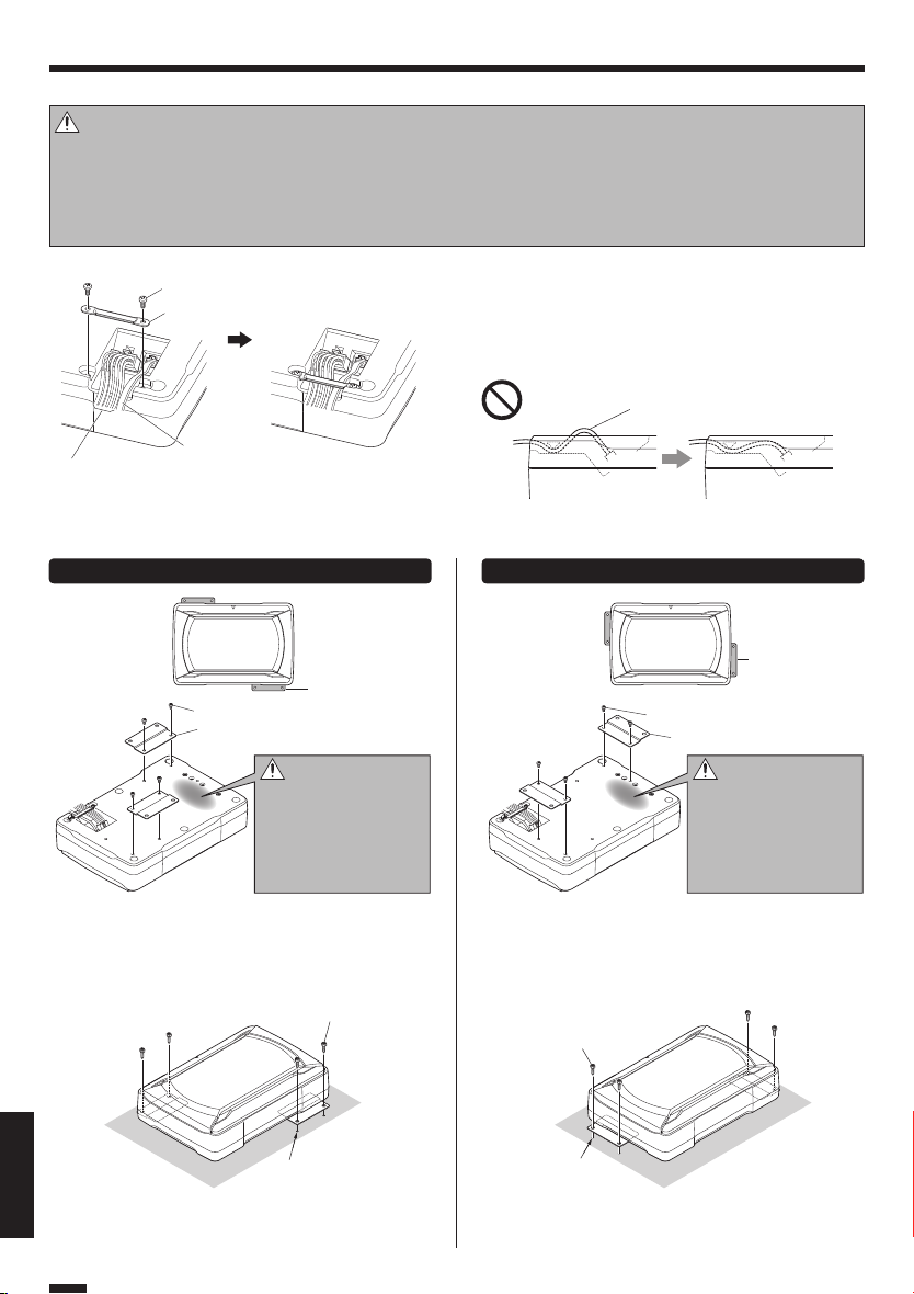
Installeren
Alvorens de luidspreker s definitief op hun plaats te installeren, moet u eerst het geluid controleren.
Opgelet:
Wanner u een gat maakt onder een stoel, in de bagageruimte of ergens anders in het voertuig, dient u te controleren of er
•
zich aan de andere kant geen gevaarlijke dingen bevinden die u zou kunnen beschadigen, zoals de benzinetank, remleidingen, of de bedradingsbundel en wees voorzichtig dat u geen krassen of andere beschadigingen maakt.
• Installeer het toestel op een plek waar het de besturing van het voertuig, het betreden of verlaten van het voertuig en de
beweging in het voertuig niet kan hinderen.
• Zet het product stevig vast zodat het niet kan bewegen als gevolg van de trillingen en stoten tijdens de rit.
Vastzetten van de bedradingVastzetten van de bedrading
■
Machineschroef x 2
8
Bevestigingsdeel B
5
Afstandsbediening
10 pens stekkersnoer
2
Vastzetten van de subwoofer
■
1
De subwoofer kan op twee manieren worden bevestigd. Selecteer de optimale bevestigingspositie van bevestigingsdeel A 4
aan de hand van de installatieplek van de subwoofer.
Bevestigingsmethode A Bevestigingsmethode B
4
11
Machineschroef x 4
7
Bevestigingsde el A x 2
4
Bevestig de Bevestigingsdeel A 4 aan de luidsprekereenheid veilig gebruik van de machineschroeven
. Wees voorzichtig, zodat de aangesloten kabels
7
niet krijgen in de eenheid tussen de spreker en Bevestigingsdeel A 4.
22
Bevestigingsdeel A
Opgelet:
Dit gedeelte wordt iets
heter dan andere onderdelen omdat het functioneert als koeling voor
de door de versterker
gegenereerde warmte.
Zelftapp ende schroef x 4
6
Sluit de 10 pens stekkersnoer 2 en de afstandsbediening 1 aan op de luidsprekereenheid.
Bevestig de bedrading aan de luidsprekereenheid
met bevestigingsdeel B 5 en zet deze vast met de
machineschroeven 8.
Verb od!
Zet he t snoer zo vas t dat dit
niet uit de zijkant van de luidsprekereenheid steekt.
4
Bevestigingsdeel A
Machineschroef x 4
7
Bevestigingsde el A x 2
4
Opgelet:
Dit gedeelte wordt iets
heter dan andere onderdelen omdat het functioneert als koeling voor
de door de versterker
gegenereerde warmte.
Bevestig de Bevestigingsdeel A 4 aan de luidsprekereenheid veilig gebruik van de machineschroeven
. Wees voorzichtig, zodat de aangesloten kabels
7
niet krijgen in de eenheid tussen de spreker en Bevestigingsdeel A 4.
Zelftapp ende schroef x 4
6
Boor vier gaatjes voor
ø 3,6 mm schroeven voor.
Boor gaatjes voor ø 3,6 mm schroeven in een metalen
deel van het voe rtuig en bevestig de luidsprekereenheid
NEDERLANDS
aan het voertuig met de zelftappende schroeven 6.
Nederlands
28
Boor vier gaatjes voor
ø 3,6 mm schroeven voor.
Boor gaatjes voor ø 3,6 mm schroeven in een metalen
deel van het voe rtuig en bevestig de luidsprekereenheid
aan het voertuig met de zelftappende schroeven 6.
Page 29

Installeren van de afstandsbediening
■
Installeer de afstandsbediening in het voertuig met
behulp van het meegeleverde klittenband.
Afstandsbediening
1
(Achterpaneel)
Voertuig
Klittenband
9
(harder opper vlak)
Klittenband
9
(zachter oppervlak)
Vervangen van de zekering
Vervang de zekering door
een zekering met dezelfde
stroomsterkte.
Verwijderen
■
Zekering
Open de afdekking.
1
Neem de zekering vast met uw vingers en trek ze
2
omhoog.
Opgelet: Vervang de zekering door een zekering met dezelfde capaciteit (stroomsterkte), zoals
Afdekking
Zekeringhouder
aangegeven op de zekering. Deze zekering heeft een stroomsterkte van 10A.
Plaatsen
■
Reservezekering
10 A
Plaats de zekering voorzichtig in de zekeringhouder
1
en druk ze volledig in met uw vinger.
Sluit de afdekking.
2
Bediening
Naam van elk onderdeel (Afstandsbediening)
■
Verlichting
Wanneer de stroom wordt
ingeschakeld, zal de verlichting aan
gaan.
VOLUME regelaar
(Ingangsgevoeligheid instelknop)
FREQUENCY regelaar
(Afsnijd-frequentie instelknop)
PHASE schakelaar
(Fase keuzeschakelaar)
■
(afstandsbediening)
1
Verdraai de FREQUENCY regelaar om de balans tussen de lage
tonen van de achter luidsprekers en de lage tonen van deze
luidspreker als gewenst in te s tellen.
Geluidsdrukniveau
2
De lage frequentietoon is mogelijk variabel afhankelijk van
de positie van deze luidspreker, de richting of de overgangsfrequentie. U kunt dit indien nodig bijstell en me t de PHASE
schakelaar. Druk deze schakelaar in de stand waarbij het geluid
volgens u het beste is.
[0°] geeft de normale fase aan ter wijl [180°] de aanduiding is
voor de omgekeerde fase.
Opgelet:
Installeer de afstandsbediening zodat deze niet in de weg
zit bij het besturen van de auto.
Vermijd plekken waar de af standsbediening bloot kan
staan aan direct zonlicht of de hete luchtstroom van de
verwarming. Anders kan het product te lijden krijgen, hetgeen kan resulteren in brandgevaar.
Maak de installatieplek netjes schoon voor u het klittenband aanbrengt.
A
0
1
Instellen van de geluidsweergave
Verdraai de FREQUENCY instelknop om de af-
snijd-frequentie in te stellen (frequenties hoger
dan de ingestelde frequentie zullen worden afgesneden).
50 Hz
125 Hz
Laag Hoog
Laag Hoog
Stel de lage frequentiefase in.
Frequ entie
Ook wanneer de afstandsbediening niet is aangesloten
zal er geluid worden weergegeven, maar de bedieningsmethoden zoals beschreven in dit gedeelte zijn
dan niet beschikbaar.
In dit geval worden het volume, de afsnijdfrequentie
en de fase ingesteld op de voorgeprogrammeerde
standaardinstellingen, waarbij de afsnijdfrequentie
wordt ingesteld op 125 Hz en de fase op 0º (positief ).
Draai aan de VOLUME instelknop om de lage fre-
3
quenties in te stellen op het gewenste niveau.
Lager
volume
Nederlands
Hoger
volume
NEDERLANDS
29
Page 30

Oplossen van problemen
Problemen worden v aak veroorzaakt door een onjuiste bediening.
Zie daarom de onderstaande tabel alvorens de luidspreker voor reparatie weg te brengen indien er iets mis lijkt te zijn.
Probleem Oorzaak Oplossing
De stroom k an niet
worden inge schakeld (de
verlicht ing gaat niet aan).
Geen geluid
Het geluid klinkt zacht.
De geluidsk waliteit is
slecht (ge luid is vervormd).
Het geluid is onnatuurlijk.
De afstandsbediening
doet het niet.
De ve rl ic hting van de afstandsbediening licht niet
op.
• De zekering is doorgebrand. • C o n t r o l e e r d e ( +)/ ( - ) p o l a r it e i t v a n h e t
• De stroomvo orzieningspen (geel) van de 10pens snoer-aansluiting is niet doorverbonden.
• De stroombedieningspen (blauw/wit) van de
10-pens snoer-aansluiting is niet doorverbonden.
• De aardingspen (zwart) van de 10-pens snoeraan-sluiting is niet doorverbonden.
• De 10-pens stekker is niet goed aangesloten.
• De negatieve (-) kabel van de accu van de auto
is losgekoppeld.
• De demper van de centrale eenheid staat aan
(ON).
• De VOLUME instelling staat op de laagste (MIN)
stand.
• De luidspreker-snoeren zijn niet op de juiste
manier aangesloten.
• De aansluitingen zijn niet op de juiste manier
gemaakt.
• Het ingangsniveau staat te laag. • Verdraai de VOLUME instelknop en stel het in-
• De aansluitingen zijn niet op de juiste manier
gemaakt.
• Het ingangsniveau staat te hoog. • Verdraai de VOLUME instelknop en stel het in-
• De luidspreker-snoeren zijn aangesloten met
omgekeerde positieve (+) en negatieve (-) polariteit.
• De aardingspen (zwart) van de 10-pens snoeraan-sluiting is niet goed doorverbonden.
• Het sno er v an d e af st an dsbe diening i s ni et
aangesloten.
stroomsnoer en of de bedrading nergens kortgesloten is en vervang vervolgens de zekering
door een met het opgegeven vermogen.
• Sluit de snoeren op de juiste manier aan door
het aansluitingsvoorbeeld op blz. 26, 27 te
raadplegen.
• Sluit het snoer o p de juiste manier aan door
het aansluitingsvoorbeeld op blz. 26, 27 te
raadplegen.
• Controleer alle verbindingen van alle snoeren
en sluit vervolg ens de (-) kabel weer op de accu
aan.
• Stee k de stekker er goed in.
• Bevestig de aarding aan een metalen gedeelte
van het voe rtuig (n ie t aan ee n ge lakt d eel)
door het goed vast te schroeven.
• Controleer alle verbindingen van alle snoeren
en sluit vervolgens de (-) kabel weer door de
accu aan.
• Schakel de demping uit.
• Stel het volume in op het optimale niveau door
blz. 29 te raadplegen.
• Sluit het snoer o p de juiste manier aan door
het aansluitingsvoorbeeld op blz. 26 te raadplegen.
• Steek de stekkers helemaal in de aanslui tingen.
gangsniveau in op een geschikt niveau.
• Verbind het snoer met de REMOTE aansluiting.
• Controleer of het RCA (tulpstekker) snoer op
de juiste manier is aangesloten.
gangsniveau in op een geschikt niveau.
• Sluit de snoeren op de juiste manier aan door
het aansluitingsvoorbeeld op blz. 26, 27 te
raadplegen.
• Bevestig de aarding aan een metalen gedeelte
van het voe rtuig (n ie t aan ee n ge lakt d eel)
door het goed vast te schroeven.
• Verbind het snoer met de REMOTE aansluiting.
• Stee k de stekker er goed in.
Technische gegevens
De hieronder vermelde technische gegevens en het ontwerp zijn vatbaar voor wijzigingen zonder kennisgeving met het oog op verbetering.
Max. uitg angsvermogen ..................................................150 W
Frequenti erespons ............................................. 35 Hz - 150 Hz
Frequenti e afkappen .......................................... 50 Hz - 125 Hz
Fase ...................................................................................0˚, 180˚
Ingangsgevoeligheid/impedantie
LINE IN .............................................................. 50 mV / 22 kΩ
NEDERLANDS
Nederlands
30
Voeding ............ 14,4 V gel ijkstroom (11 V - 16 V toelaa tbaar)
Maximumve rbruik ............................................................. 8,5 A
Zekering ................................................................................ 10 A
Gevoelig heid .......................................110 dB (in het voertui g)
Buitenaf metingen ........................................ Breedte : 280 m m
Hoo gte: 70 mm
Die pte: 190 mm
Gewicht (net to)..................................................................2,8 kg
Page 31

KSC-SW11
SUBWOOFER CON AMPLIFICATORE E CASSA
ISTRUZIONI PER L'USO
ALTAVOZ DE SUBGRAVES CON CERRADO ALIMENTACION
MANUAL DE INSTRUCCIONES
SUBWOOFER COM AMPLIFICADOR E CAIXA
MANUAL DE INSTRUÇÕES
АКТИВНЫЙ САБВУФЕР
ИНСТРУКЦИЯ ПO ЭKCПЛУATAЦИИ
ITALIANO ESPAÑOL PORTUGUÊS РУССКИЙ
Page 32

NORME IMPORTANTI DE SICUREZZA
Attenzione: Per un uso sicuro dell’apparecchio, leggete attentamente questa pagina.
AVVERTENZA AVV ERTENZ A
• Prima di effettuare il montaggio o il cablaggio, ecc., assicuratevi di rimuovere il cavo dal terminale negativo della
batteria. (Altrimenti si può verificare un corto circuito o un
incendio.)
• Nel posare I cavi di accensione, della batteria e di messa
a terra, usare cavi per automobile o di altro tipo da 0,75
2
di sezione (AWG 18) o più per evitare che si deterio-
mm
rino e che il loro isolamento si consumi eccessivamente.
• Per evitare corto circuiti, non lasciare mai degli oggetti
metallici, ad esempio monete ed utensili, all’interno del
diffusore.
• Se l’unità generasse odori anormali, spegnere la subito.
Entrate quindi immediatamente in contatto con il vostro
rivenditore di fiducia.
SPEGNIMENTO!
• Collegare il diffusore ad una sorgente di c.c. a 12 V, terra
negativa.
• Non tentate di aprire o modificare l’unità, dato che ciò
potrebbe causare incendi o errori di funzionamento.
• Estratta l’unità dal sacchetto in polietilene, gettatelo in
modo che non possa cadere in mano a bambini. Essi potrebbero altrimenti rimanere soffocati.
ATTENZIONE ATTE NZI ONE
• L’installazione ed i collegamenti elet trici del prodot to
richidono abilità ed esperienza. Per assicurare la sicurezza,
accertarsi di far eseguire l’installazione ed i collegamenti
elettrici dal proprio rivenditore o operaio specializzato.
• Non installare il diffusore in luoghi esposti a luce solare
diretta o calore eccessivo.
• Non installate I diffusori in posizioni esposte ad acqua ed
umidità.
• Non Installate I diffusori in posizioni pericolose o instabili
ITALIANO
o esposte a polvere e sporco.
• Se dovesse saltare il fusibile, controllate innanzitutto se è
in corto il cavo, poi sostituite il fusibile con uno del tipo
indicato (con l’amperaggio giusto) sulla scatola del fusibile.
(L’utilizzo di fusibili diversi da quello indicato può causare
un incendio.)
Controllate il display!
Per sostituire il fusibile, fate riferimento al manuale delle
istruzioni dei veicolo.
• Per prevenire corto circuiti durante la sostituzione di un
fusibile, scollegare per prima cosa il fascio fili.
• Non usare benzina, nafta o solventi per pulire il diffusore.
Usare solo un panno morbido e pulito.
• Collegare i cavi del diffusore ai connettori appropriati
separatamente. Condividendo il filo negativo o la messa
a terra dei due diffusori in un punto metallico del telaio
della vettura il sistema può non funzionare.
• Quando si apre un foro sotto il sedile, all’interno del bagagliaio o in un altro punto del veicolo, controllare che
con vi sia alcun oggetto pericoloso dall’altra parte, ad
esempio il serbatoio di benzina, le tubazioni dei freni o un
fascio fili, e fare inoltre attenzione a non graffiare o danneggiare parti in vista.
• Per un cablaggio con messa a terra, non dovete fissare il
cavo all’airbag, al sistema dello sterzo o a quello frenante
né a dei bulloni o dati delle unità di sicurezza.
(Altrimenti si possono verificare degli incidenti.)
• Quando effettuate il montaggio, assicuratevi che il luogo
di installazione dell’unità non causerà dei fastidi durante
la guida né pericoli ai passeggeri per via di una frenata
improvvisa, ecc.
(Causa di lesioni personali o incidenti.)
• Installata l’unità, controllare che le varie spie, le frecce, I
tergicristallo e le altre parti elettriche funzionino in modo
normale.
• Prima di fare quanto segue, il conducente deve sempre
fermare il veicolo in un luogo sicuro.
– Uso del telecomando
• Non usare il prodotto per scopi che non siano l’installazione su di un veicolo.
Dichiarazione di conformità relativa
alla direttiva EMC 2014/30/UE
Dichiarazione di conformità relativa
Produttore:
JVC KENWOOD Corporation
3-12 Moriya-cho, Kanagawa-ku, Yokohama-shi,
Kanagawa, 221-0022, JAPAN
Rappresentante UE:
JVCKENWOOD Europe B.V.
Amsterdamseweg 37, 1422 AC Uithoorn, PAESI BASSI
Informazioni sullo smaltimento delle vecchie apparecchiature elettriche ed elettroniche (valido per i
paesi che hanno adottato sistemi di raccolta separata)
Per conoscere dove e come recapitare tali prodotti
nel luogo a voi più vicino, contattare l’apposito ufficio
comunale. Un appropriato riciclo e smaltimento aiuta
a conservare la natura e a prevenire effetti nocivi alla
salute e all’ambiente.
alla direttiva RoHS 2011/65/UE
I prodotti recanti il simbolo di un contenitore
di spazzatura su ruote barrato non possono
essere smaltiti insieme ai normali rifiuti di
casa. I vecchi prodotti elettrici ed elettronici
devono essere riciclati presso una apposita
struttura in grado di trattare questi prodotti e
di smaltirne i loro componenti.
Italiano
2
Page 33

Parti accluse
No. Nome della parte Forma esterna Quantità No. Nome della parte Forma esterna Quantità
Telecomando
1
(5 m)
10-Cavo di collegamen-
2
to (5 m)
Cavo del diffusore
3
(4,3 m)
Montaggio A 2
4
Montaggio B 1
5
1
1
1
Vite filet tante
6
(ø 5 × 16 mm)
Vite per macchina
7
(M4 × 5 mm)
Vite per macchina
8
(M3 × 8 mm)
Chiusura a strappo
(Adesivo a due lati/
9
per telecomando)
4
4
2
1
Collegamento
Attenzione:
Prima di eseguire i collegamenti elettrici, accertarsi di rimuovere il cavo dal terminale negativo della batteria. Dopo aver terminato tutti i collegamenti, controllare nuovamente che siano corretti. Dopo tale controllo, ricollegare il cavo al terminale negativo della batteria.
Terminali del subwoofer
■
Terminale POWER/SPEAK ER INPUT
Ter mina le R EMOT E
Collegamento del telecomando
■
Telecomando
1
Collegare con la par te
da bloccare della presa
del telecomando rivolta
verso il basso.
Note:
• Non mancare di collegare l’unità di telecomando in dotazione.
• Se il cavo non fosse collegato correttamente, l’illuminazione dell’unità di telecomando in dotazione potrebbe non avvenire.
• Non inserire il connettore dell’unità di telecomando rovescio o con forza. Si potrebbero causare altrimenti delle disfunzioni.
Parte da bloccare
della presa
Si illumina di luce blu.
Quando si accende
l'unità, si accende
l'illuminazione.
Italiano
ITALIANO
3
Page 34
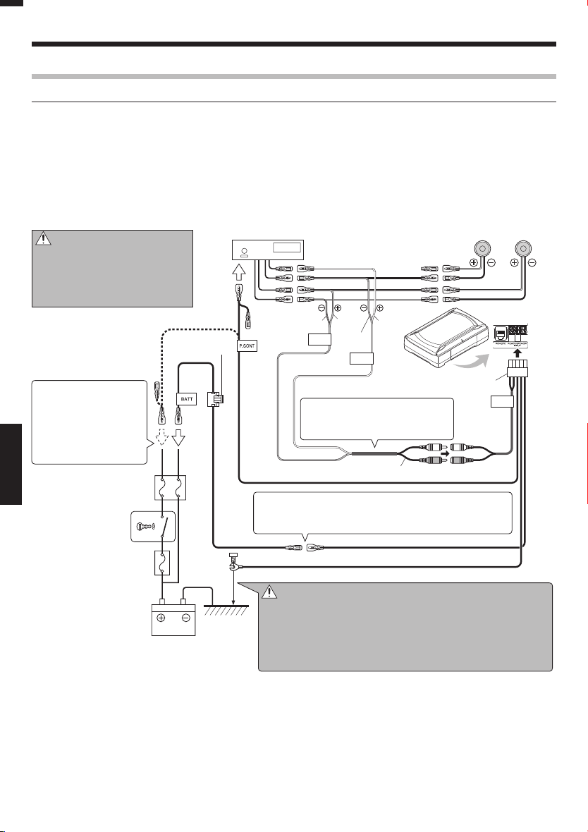
Collegamento
Collegamenti di ingresso del telecomando
Collegare il subwoofer ai cavi di uscita dei diffusori anteriori o posteriori dell’unità centrale.
Note:
• Leggere i manuali di istruzioni dei componenti collegati oltre a questo manuale di istruzioni.
• Quando l'unità centrale incorpora un DSP, non collegare nulla all'uscita posteriore, dato che l'effetto di riproduzione delle basse frequenze potrebbe venire attenuato dall'effetto DSP.
Esempio
■
Quanto segue mostra un collegamento tipico per un efficace godimento di un impianto stereo per auto. Collegare il proprio
impianto fa cendo riferimento all ’esempio.
Attenzione:
Non stendere i cavi in modo tale che
possano venire presi da una parte del
veicolo e danneggiati. Si potrebbero
altrimenti avere folgorazioni o incendi dovuti a corto circuiti.
Se non c'è nessun terminale di controllo dell'alimentazione nell'unità centrale,
collegate i fili blu e bianco
alla linea accessoria (linea di
posizione ACC della chiave
di accensione).
ITALIANO
Interruttore della
chiave di accensione
Scatola fusibili della ve ttura
(fusibile principale)
Scatola fusibili
della vettura
Fusibile 10A
Unità centrale
Bianco
CenereCenere/Ne ro
SP.R
Bianco/
INPUT
Nero
SP.L
INPUT
10-Cavo di collegamento
2
Non piegare la sezione del cavo
del diffusore rivestita in vinile. Si
potrebbero altrimenti avere guasti.
Cavo del diffusore
Blu/Bianco
Se a motore acceso i diffusori producono un ronzio, collegate
un filtro del rumore (in vendita separatamente) al filo di alimentazione.
Giallo Giallo
Nero
3
Diffuso ri anteriori o posteriori
Sinistra Destra
KSC-SW11
LINE IN
※
Batteria
Italiano
4
Attenzione:
GND
※
Collegate il terminale di massa del cavo nero direttamente con una
vite su una parte di metallo nudo del veicolo,. Se accendete la corrente su ON senza aver collegato questo terminale, si può danneggiare il sistema stereo. Assicuratevi di collegarlo. Inoltre, i pannelli
di metallo verniciati non sono messi a terra e non funzioneranno
correttamente. Fate attenzione a questo.
Page 35

Collegamenti di ingresso RCA
Collegare il subwoofer all’uscita del subwoofer (uscita non-fader) o alle prese RCA per l’uscita anteriore
dell’unità centrale.
Note:
• Leggere i manuali di istruzioni dei componenti collegati, come l’unità centrale, oltre a questo manuale di istruzioni.
• Si prega di acquistare separatamente un cavo RCA reperibile in commercio.
• Quando l’unità centrale incorpora un DSP, collegare il subwoofer all’uscita del subwoofer (uscita non-fader) o alle prese RCA
per l’uscita anteriore. Non collegare le prese RCA per l’uscita posteriore dato che l’effetto di riproduzione delle basse frequenza potrebbe essere attenuato a causa dell’effetto DSP.
Esempio
■
Quanto segue mostra un collegamento tipico per un efficace godimento di un impianto stereo per auto. Collegare il proprio
impianto fa cendo riferimento all ’esempio.
Attenzione:
Non stendere i cavi in modo tale che possano venire presi da una parte del veicolo e
danneggiati. Si potrebbero altrimenti avere
folgorazioni o incendi dovuti a corto circuiti.
Fusibile 10A
Se non c'è nessun terminale di controllo dell'alimentazione nell'unità centrale,
collegate i fili blu e bianco
alla linea accessoria (linea di
posizione ACC della chiave
di accensione).
Scatola fusibili
della vettura
Interruttore della
chiave di accensione
Scatola fusibili della ve ttura
(fusibile principale)
Se a motore acceso i diffusori producono un ronzio, collegate
un filtro del rumore (in vendita separatamente) al filo di alimentazione.
Unità centrale
(SUB WOOFER OUT,
Uscita non-fader)
Blu/Bianco
Giallo Giallo
Nero
10-Cavo di collegamento
2
Cavo RCA
(disp onibile i n commercio)
KSC-SW11
LINE IN
ITALIANO
※
GND
※
Batteria
Unità centrale
Cavo RCA
(disponibi le in
commercio)
KSC-SW11
Quando l’uscita dell’unità centrale è una singola presa
RCA, usare un cavo RCA che converta l’uscita nelle due
prese RCA come mostrato sopra. L’uscita del subwoofer
verrà dimezzata se non si utilizza il cavo di conversione.
Attenzione:
Collegate il terminale di massa del cavo nero direttamente con una
vite su una parte di metallo nudo del veicolo,. Se accendete la corrente su ON senza aver collegato questo terminale, si può danneggiare il sistema stereo. Assicuratevi di collegarlo. Inoltre, i pannelli
di metallo verniciati non sono messi a terra e non funzioneranno
correttamente. Fate attenzione a questo.
Italiano
5
Page 36

Installazione
Prima di fissare il diffusore in p osizione, controllarne il suono.
Attenzione:
• Quando si apre un foro sotto il sedile, all’interno del bagagliaio o in un altro punto del veicolo, controllare che con vi sia alcun oggetto pericoloso dall’altra parte, ad esempio il serbatoio di benzina, le tubazioni dei freni o un fascio fili, e fare inoltre
attenzione a non graffiare o danneggiare parti in vista.
Installare in una posizione che non disturba la guida, l’ingresso o l’uscita dal veicolo ed i movimenti all’interno della cabina del veicolo.
•
• Fissare saldamente il prodotto in modo che non possa muoversi a causa di vibrazioni o urti durante la guida.
Fissaggio del cavo in posizioneFissaggio del cavo in posizione
■
Vite per macchina x 2
8
Montaggio B
5
Collegare il 10-cavo di collegamento della spina 2 ed
il telecomando 1 al diffusore.
Fissare i cavi del diffusore con il montaggio B 5 e fissarlo al suo posto con le viti per macchina
.
8
Telecomando
10-Cavo di collegamento
2
Fissaggio del subwoofer
■
1
Divieto!
Fissare il cavo in modo che non
protruda dal lato del diffusore.
Il subwoofer può venire fissato in due modi. Scegliere la posizione di applicazione ottimale del montaggio A 4 a seconda
della posizione di installazione del subwoofer.
Metodo di ssaggio A Metodo di ssaggio B
Montaggio A
4
Montaggio A
11
Vite per macchina x 4
7
Montaggio A x 2
4
4
Vite per macchina x 4
7
Montaggio A x 2
4
ITALIANO
Attenzione:
Questa parte diviene leggermente più calda delle
altre par ti poiché funge
da radiatore per il calore
generato dall’amplificatore.
Attaccate i montaggio A 4 sull'unità altoparlante
in modo ben saldo usando le viti per macchina 7.
Badare a che i cavi collegati non si frappongano fra il
diffusore e i montaggio A 4.
22
Vite filet tante x 4
6
Attaccate i montaggio A 4 sull'unità altoparlante
in modo ben saldo usando le viti per macchina 7.
Badare a che i cavi collegati non si frappongano fra il
diffusore e i montaggio A 4.
Vite filet tante x 4
6
Attenzione:
Questa parte diviene leggermente più calda delle
altre par ti poiché funge
da radiatore per il calore
generato dall’amplificatore.
Praticare quattro fori
pilota per viti da ø3,6 mm.
Praticare i fori pilota per le viti da ø3,6 mm nella parete metallica del veicolo ed applicare il diffusore al
veicolo utilizzando le viti filettanti 6.
Italiano
6
Praticare quattro fori
pilota per viti da ø3,6 mm.
Praticare i fori pilota per le viti da ø3,6 mm nella parete metallica del veicolo ed applicare il diffusore al
veicolo utilizzando le viti filettanti 6.
Page 37

Installazione del telecomando
■
Ins tallare l’unità di telecomando in dotazione sul
veicolo facendo uso della chiusura a strappo in dotazione.
Chiusura a strappo
9
(superficie più dura)
Telecomando
1
(Pannello posteriore)
Veico lo
Chiusura a strappo
9
(superificie più morbida)
Sostituzione del fusibile
Sostituite il fusibile solo con uno dall'amperaggio speci ficato. Sostituite il fusibile
solo con uno dall'amperaggio specif icato.
Rimozione
■
Fusibi le
Aprire il coperchio.
1
Prenderlo il fusibile e tirare.
2
Coperchio
Porta f usibile
Attenzione: Assicuratevi di sostituire il fusibile con uno dallo stesso amperaggio.
Funzionamento
Nomenclatura (Telecomando)
■
Illuminazione
Quando si accende l'unità, si accende
l'illuminazione.
Manopola VOLUME
(Manopola di controllo sensibilità in
ingresso)
Manopola FREQUENCY
(Manopola di controllo frequenza di
taglio)
Comando PHASE
(Selettore di fase)
Attenzione:
Installare il telecomando in una posizione in cui non intralci la guida.
Evitare di installarlo in luoghi soggetti a luce solare diretta
o aria calda dall'impianto di riscaldamento. In caso contrario il prodotto potrebbe degradare e si potrebbero avere
rischi di fiamme.
Prima di applicare la chiusura a strappo, pulire bene la sua
posizione di applicazione.
Questo è un fusibile da 10A.
Installazione
■
Fusibi le di
sostituzione 10 A
Installate il fusibile delicatamente nel porta fusibile e
1
premetelo comple-tamente verso l’interno con il dito.
Chiudere il coperchio.
2
Regolazione del suono
■
(Funzionamento telecomando)
Ruotare la manopola di controllo FREQUENCY per
1
regolare la frequenza di taglio (le frequenze più
alte di questa frequenza vengono tagliate).
Ruotare la manopola FREQUENCY per regolare il bilanciamento
tra i bassi dei diffusori posteriori ed i bassi di questa unità come
desiderato.
Intensità suono
Regolare la fase delle basse frequenze.
2
Il tono delle basse frequenze potrebbe variare a seconda della
posizione dell'unità, del suo orientamento o della frequenza di
turn-over. Ciò può essere regolato cambiando la posizione del
comando PHASE. Impostare questo comando su una delle due
posizioni a seconda delle proprie preferenze.
[0°] indica la fase normale e [180°] indica la fase inversa.
50 Hz
125 Hz
Bassa Alta
Frequ enza
Bassa Alta
A
0
1
ITALIANO
L’audio viene prodotto anche quando l’unità di telecomando in dotazione non è collegata, ma in tal caso le
operazioni descritte in questa sezione non sono possibili.
In tal caso, il volume, la frequenza di taglio e la fase
vengono regolati sui valori prede niti, con i quali la frequenza di taglio è di 125 Hz e la fase 0° (positiva).
Ruotare la manopola di controllo VOLUME per re-
3
golare le basse frequenze sul livello desiderato.
Per diminuire
il volume
Per aumentar e
il volume
Italiano
7
Page 38

Guida alla Soluzione di Problemi
Spesso, apparenti malf unzionamenti sono dovuti a un errore dell'utilizzatore. Prima di richiedere riparazioni, consultare le seguenti tabelle.
Problema Causa Rimedio
L'unità non si accend e
(l'illuminazione non si
accende).
Nessun suono
Il suono è esi le.
La qualit à sonora è cattiva
(il suono è dis torto).
ITALIANO
Il suono è inn aturale.
Il tel ecoma nd o non f un ziona.
L’unità di telecomando in
dotazio ne non si accende.
• Un fusibile è saltato. • Controllare che le polarità (+) e (-) del cavo di
• Il piedino di alimentazion e giallo del cavo di
collegamento a 10 piedini non è collegato.
• Il piedino di alimentazione blu/bianco del cavo
di collegamento a 10 piedini n on è collegato.
• Il piedino nero di messa a terra del cavo di collegamento a 10 piedini non è collegato.
• Il connettore a 10 piedini non è ben collegato.
• Il cavo negativo (-) della batteria è scollegato. • Controllare i collegamenti di tutti i cavi e quin -
• L'attenuatore dell'unità centrale è stato portato
su On.
• Il comando VOLUME si trova sulla posizione di
minimo.
• I cavi dei dif fusori non sono collegati corret tamente.
• I terminali di collegamento non sono collegati
correttamente.
• Il livello in ingresso è imp ostato troppo basso. • Ruo tare la ma nopola di control lo VO LUME e
• I terminali di collegamento non sono collegati
correttamente.
• Il livello in ingresso è impostato troppo alto. • Ruotare la manopola di c ontrollo VOLUME e
• I cavi dei diff usori sono collegati alla polarità (+)
e (-) scorretta.
• Il piedino nero di messa a terra del cavo di collegamento a 10 piedini non è collegato.
• Il cavo di telecomand o è scollegato. • Collegare il cavo al terminale REMOTE.
alimentaz ione e de gli a ltr i cav i non siano in
corto circuito e se necessario sostituire il fusibile installato con un altro del giusto amperaggio.
• Ricollegare i cavi correttame nte consultando in
proposito l'esempio di coll egamento a pag
• Colle gare il cavo correttamente consultan do
l'esempio a pag
• Applicare il cavo di messa a terra ad una sezione metallica del veicolo, e non ad una dipinta
fissandolo f ermamente con la vite.
• Inserire a fondo il connettore.
• Controllare i collegamenti di tutti i cavi e quindi collegare il cavo (-) della bat teria.
di collegare il cavo (-) della bat teria.
• Disattivare l'attenuatore.
• Aumentare il volume portandolo ad un livello
ottimale a pag
• Colle gare il cavo correttamente consultan do
l'esempio a pag
• Inserire i connettori o gli spinotti a fondo nei
terminali.
impostare il livello in ingresso su un livello ottimale.
• Collegare il cavo al terminale REMOTE.
• Controllare che il cavo RCA sia collegato correttamente.
impostare il livello in ingresso su un livello ottimale.
• Colle gare il cavo correttamente consultan do
l'esempio a pag
• Applicare il terminale di messa a terra ad una
sezione metallica e non dipinta del telaio avvitandone fermamente la vite.
• Inserire a fondo il connettore.
4, 5.
7.
4.
4, 5.
4, 5.
Caratteristiche tecniche
I seguenti valori nominali ed il design sono s oggetti a modifiche senz a preavviso.
Uscita mas sima ..................................................................150 W
Rispost a in frequenza ......................................... 35 Hz - 150 Hz
Taglio della fre quenza ........................................ 50 Hz - 125 Hz
Fase ...................................................................................0˚, 180˚
Sensibilità/impedenza di ingresso
LINE IN .............................................................. 50 mV / 22 kΩ
Italiano
8
Alimenta zione ........ CC 14,4 V (Gamma oper ativa 11 V - 16 V)
Consumo corr ente massimo ............................................. 8,5 A
Capacità d el fusibile ............................................................10 A
Sensibil ità ............................................. 110 dB (in automobile)
Dimensi oni esterne .................................L arghezza: 280 mm
Altezza: 70 mm
Profon dità: 190 mm
Peso (netto) ........................................................................2,8 kg
Page 39

Italiano
ITALIANO
9
Page 40

INSTRUCCIONES DE SEGURIDAD IMPORTANTES
Precaución : Lea cuidadosamente estas páginas para asegurar una operación sin anomalías.
ADVERTENCIA ADVERTENCIA
• Antes de realizar el montaje o el cableado, etc., asegúrese
de retirar el cable del terminal negativo de la batería.
(De lo contrario pueden producirse cor tocircuitos o in-
cendios).
• Cuando extie nda los cables de encendido, batería o
masa, asegúrese de utilizar cables para uso en automóviles u otros cables de 0,75 mm
pedir que se deterioren los propios cables o se desgaste
el revestimiento.
• Para impedir cortocircuitos, nunca ponga o deje objetos
metálicos (tales como monedas o herramientas metálicas) en el interior de un altavoz.
• En el caso de que la unidad genere humo o un ruido
anormal, desconecte inmediatamente la alimentación.
Después, consulte con su concesionario o centro de reparaciones más cercano tan pronto como sea posible.
DESCONECTE LA ALIMENTACION!
• Conecte el altavoz a una batería de 12 V CC con puesta a
masa negativa.
• No trate de abrir ni modificar la unidad porque podría
producirse un peligro de incendio o una avería.
• Después de cesar la unidad de la bolsa de polietileno,
asegúrese de poner la bolsa de polietileno donde no
puedan alcanzarla los niños. De otra forma, éstos podrán
jugar con la bolsa y se podría producir un peligro de asfixia.
2
(AWG 18) o más, para im-
• Cuando haga un agujero debajo de un asiento, en el portamaletas o en cualquier otro punto del vehículo, compruebe que no haya nada peligroso al otro lado como,
por ejemplo, un deposito de gasolina, tubería de frenos
o conjuntos de cables, y tenga cuidado para no dejar
marcas y hacer otros daños.
• Para el montaje de tierra no sujete el cable a un airbag,
la dirección o el sistema de frenado ni a ningún tornillo o
tuerca críticos de la unidad de seguridad.
(Puede producir accidentes.)
• Durante el montaje, asegúrese de realizar el mismo en
un sitio que no interfiera con la conducción o que resulte
peligroso para los pasajeros al frenar bruscamente, etc.
(Causa de lesiones o accidentes).
• Después de instalar la unidad, asegúrese de que el equipo eléctrico tal como luces de frenos, luces de intermitentes y limpiaparabrisas funcionen normalmente.
• El conductor deberá parar siempre el vehículo en un lugar seguro antes de hacer lo siguiente.
– Utilizar el mando a distancia
• No utilice el producto con ningún otro propósito que no
sea montarlo a bordo.
PRECAUCIÓN PRECAUCIÓN
• La instalación y cableado del producto requiere la habilidad y la experiencia de los expertos. Para garantizar la
seguridad, cerciórese de que sea su concesionario o un
especialista quien realice la instalación y el cableado.
• No instale el altavoz en un lugar expuesto a la luz solar
directa o a un calor o humedad excesivo.
• No instale los altavoces en lugares sometieses al agua o a
la humedad.
• No instale los altavoces en lugares inestables ni en lugares donde haya polvo.
• Si saltara el fusible, después de comprobar si el cable
ha sufrido un cortocircuito, asegúrese de reemplazarlo
por un fusible de la capacidad (amperaje) estipulada, tal
como se indica en la caja de fusibles.
ESPAÑOL
(El uso de fusibles de una capacidad que no sea la estipu-
lada, puede ser motivo de incendios).
¡Compruebe las indicaciones!
Para cambiar el fusible, remítase al manual de instruccio-
nes del vehículo.
• Para impedir un cortocircuito cuando sustituya un fusible,
desconecte primero el conjunto de los cables.
• No utilice gasolina, naf talina u otro tipo de disolvente
para limpiar el altavoz. Limpielo pasando un paño blando
y seco.
• Conecte separadamente los cables de los altavoces a los
conectores de altavoces apropiados. Compartir el cable
negativo del altavoz o poner a masa los cables del altavoz
en la carrocería del automóvil puede ser la causa de que
esta unidad no funcione bien.
Español
10
Declaración de conformidad con respecto a la Directiva EMC 2014/30/UE
Declaración de conformidad con respecto a la Directiva RoHS 2011/65/UE
Fabricante:
JVC KENWOOD Corporation
3-12 Moriya-cho, Kanagawa-ku, Yokohama-shi,
Kanagawa, 221-0022, JAPAN
Representante en la UE:
JVCKENWOOD Europe B.V.
Amsterdamseweg 37, 1422 AC Uithoorn, PAÍSES BAJOS
Información acerca de la eliminación de equipos
eléctricos y electrónicos al final de la vida útil (aplicable a los países que hayan adoptado sistemas
independientes de recogida de residuos)
Los productos con el símbolo de un contenedor con ruedas tachado no podrán ser
desechados como residuos domésticos. Los
equipos eléctricos y electrónicos al final de la
vida útil, deberán ser reciclados en instalaciones que puedan dar el tratamiento adecuado
a estos productos y a sus subproductos resi-
duales correspondientes.
Póngase en contacto con su administración local para
obtener información sobre el punto de recogida más
cercano. Un tratamiento correcto del reciclaje y la eliminación de residuos ayuda a conservar los recursos y
evita al mismo tiempo efectos perjudiciales en la salud
y el medio ambiente.
Page 41

Piezas incluidas
Nº Nombre de pieza Forma externa Cantidad Nº Nombre de pieza Forma externa Cantidad
Mando a distancia
1
(5 m)
Cable conec tor de 10
2
contactos (5 m)
Cable del alt voz
3
(4,3 m)
Soporte A 2
4
Soporte B 1
5
1
1
1
Tor nill o de c ubi ert a
6
(ø 5 × 16 mm)
Tornillo para metales
7
(M4 × 5 mm)
Tornillo para metales
8
(M3 × 8 mm)
Fijador de gancho y
bucle
(Cinta con adhesivo en
9
ambos lados/para mando a distancia)
4
4
2
1
Conexión
Precaución:
Antes de hacer el cableado, asegúrese de desconectar el cable conectado al terminal negativo de la batería. Después de terminar el cableado, compruébelo de nuevo para asegurarse de que esté bien hecho. Después de terminar la comprobación,
conecte el cable al terminal negativo de la batería.
Terminales del altavoz de subgraves
■
Terminal POWER/SPEAKER INPUT
Terminal REMOTE
Conexión de la unidad de mando a distancia
■
Mando a distancia
1
Efectúe la conexión con
la parte de bloqueo de la
toma de control remoto
orientada hacia abajo.
Notas:
• Asegúrese de conectar la unidad de mando a distancia suministrada.
• Si el cable no se conecta correctamente, la iluminación de la unidad de mando a distancia no se encenderá.
• No introduzca el conector del mando a distancia al revés ni empleando fuerza. De lo contrario podría producirse un fallo en el
funcionamiento.
Parte de bloqueo
de la toma
Se enciende en color azul.
Cuando se conecta
la alimentación, la
iluminación se enciende.
Español
ESPAÑOL
11
Page 42

Conexión
Conexión de entrada de altavoz
Conecte el altavoz de subgraves a los cables de salida del altavoz delantero o del altavoz trasero de la unidad central.
Notas:
• Lea los manuales de instrucciones de los componentes conectados como, por ejemplo, la unidad central, y también este manual de instrucciones.
• Cuando la unidad central incorpora un DSP, no conecte a la salida trasera, ya que el efecto de reproducción de baja frecuencia
puede ser atenuado debido al efecto DSP.
Ejemplos
■
A continuación se muestra una conexión típica para disfrutar del equipo estéreo de automóvil. Conecte su sistema consultando el ejemplo.
Precaución:
No instale los cables donde puedan quedar agarrados por una parte de un vehículo o puedan ser dañados. De lo contrario,
podrían producirse descargas eléctricas o
incendios debidos a cortocircuitos.
Si no hubiera ningún
terminal de control de
alimentación en el centro
de la unidad, conecte los
cables azul y blanco a la
línea accesoria (línea de
posición ACC de la llave
de contacto).
Caja de fusibles
del automóvil
Llave de contacto
Caja de fusibles del
ESPAÑOL
automóvil
(Fusible principal)
Batería
Fusible 10A
※
Unidad central
Blanco
CenizaCeniza/N egro
SP.R
Blanco/
INPUT
Negro
SP.L
INPUT
No doble la sección cubierta de vinilo del
cable del altavoz. De lo contrario, podría
producirse un fallo en el funcionamiento.
Cable del alt voz
Azul/Blanco
Si se oye un ruido de zumbido procedente de los altavoces
cuando esté funcionando el motor, ponga un filtro de ruidos
(vendido por separado) en el conductor de alimentación.
Amarillo Amarillo
Negro
Precaución:
GND
※
Conecte el terminal del cable de tierra negro directamente con un
tornillo a una parte metálica sin pintar del vehículo. La activación
de la alimentación (ON) sin conectar este terminal está relacionada
con daños del sistema estéreo. Asegúrese de conectarlo. Además,
los paneles metálicos pintados, etc. no tienen masa a tierra y no
funcionarán correctamente. Tenga cuidado con esta situación.
3
Altavoces delantero o tr asero
Izquierdo Derecho
Cable conector de
2
10 co ntactos
KSC-SW11
LINE IN
12
Español
Page 43

Conexión de entrada RCA
Conecte el altavoz de subgraves a la salida de altavoz de subgraves (salida non-fader) o a las tomas RCA para la
salida delantera de la unidad central.
Notas:
• Lea los manuales de instrucciones de los componentes conectados como, por ejemplo, la unidad central, y también este manual de instrucciones.
• Compre un cable RCA opcional en tiendas especializadas.
• Cuando la unidad central incorpore un DSP, conecte el altavoz de subgraves a la salida de altavoz de subgraves (salida non-fader) o a las tomas RCA para la salida delantera. No conecte a las tomas RCA para la salida trasera, porque el efecto de la reproducción de baja frecuencia puede atenuarse debido al efecto DSP.
Ejemplos
■
A continuación se muestra una conexión típica para disfrutar del equipo estéreo de automóvil. Conecte su sistema consultando el ejemplo.
Precaución:
No instale los cables donde puedan quedar agarrados por una parte de un vehículo o puedan ser dañados. De lo contrario,
podrían producirse descargas eléctricas o
incendios debidos a cortocircuitos.
Fusible 10A
Si no hubiera ningún
terminal de control de
alimentación en el centro
de la unidad, conecte los
cables azul y blanco a la
línea accesoria (línea de
posición ACC de la llave
de contacto).
Caja de fusibles
del automóvil
Llave de contacto
Caja de fusibles del
automóvil
(Fusible principal)
Batería
Si se oye un ruido de zumbido procedente de los altavoces
cuando esté funcionando el motor, ponga un filtro de ruidos
(vendido por separado) en el conductor de alimentación.
※
GND
Unidad central
(SUB WOOFER OUT,
Salida non-fader)
KSC-SW11
Cable conector de
2
Cable RCA
(De venta en el comercio del ramo)
Azul/Blanco
Amarillo Amarillo
Negro
10 co ntactos
LINE IN
Precaución:
※
Conecte el terminal del cable de tierra negro directamente con un
tornillo a una parte metálica sin pintar del vehículo. La activación
de la alimentación (ON) sin conectar este terminal está relacionada
con daños del sistema estéreo. Asegúrese de conectarlo. Además,
los paneles metálicos pintados, etc. no tienen masa a tierra y no
funcionarán correctamente. Tenga cuidado con esta situación.
ESPAÑOL
Unidad central
Cable RCA
(De venta en el
comercio del ramo)
KSC-SW11
Cuando la salida de la unidad central sea una toma RCA
única, utilice un cable RCA que convierta la salida en dos
tomas RCA como se muestra más arriba. La salida del altavoz de subgraves se reducirá a la mitad si no se utiliza
un cable de conversión.
Español
13
Page 44

Instalación
Antes de fijar el alt avoz en su posición, ase gúrese de comprobar el sonido mientr as el altavoz se encuentra conectad o preliminarmente.
Precaución:
• Cuando haga un agujero debajo de un asiento, en el portamaletas o en cualquier otro punto del vehículo, compruebe que
no haya nada peligroso al otro lado como, por ejemplo, un deposito de gasolina, tubería de frenos o conjuntos de cables, y
tenga cuidado para no dejar marcas y hacer otros daños.
• Instale el producto en un lugar donde no interfiera con la conducción, la entrada en el vehículo y la salida del mismo, y el
movimiento dentro del vehículo.
Fije firmemente el producto de forma que no se mueva debido a las vibraciones o impactos producidos durante la conducción.
•
Fijación del cable en su lugarFijación del cable en su lugar
■
Tornillo para metales x 2
8
Soporte B
5
Mando a distancia
Cable conec tor de 10 contactos
2
Fijación del altavoz de subgraves
■
1
El altavoz de subgraves se puede fijar de dos formas. Seleccione la posición de colocación óptima del soporte A 4 de
acuerdo con la ubicación de instalación del altavoz de subgraves.
Método de jación A Método de jación B
Soporte A
11
Fije en forma segura los soportes A 4 a la unidad de
ESPAÑOL
altavoces utilizando los tornillos para metales 7.
Tornillo para metales x 4
7
Soporte A x 2
4
Tenga cuidado para que los cables conectados no
queden atrapados entre la unidad de altavoz y los
soportes A 4.
22
4
Precaución:
Esta parte se calienta un
poco más que las otras
debido a que funciona
como radiador del calor
generado por el amplificador.
Tornillo de cubierta x 4
6
Con ecte el cable conec tor de 10 contactos 2 y el
mando a distancia 1 a la unidad del altavoz.
Fije los cables a la unidad de altavoz con la soporte B
y reténgalos en su lugar con los tornillos para me-
5
tales 8.
Prohibición!
Fije el cable para que no sobresalga del costado de la unidad
del altavoz.
Soporte A
4
Tornillo para metales x 4
7
Soporte A x 2
4
Precaución:
Esta parte se calienta un
poco más que las otras
debido a que funciona
como radiador del calor
generado por el amplificador.
Fije en forma segura los soportes A 4 a la unidad de
altavoces utilizando los tornillos para metales 7.
Tenga cuidado para que los cables conectados no
queden atrapados entre la unidad de altavoz y los
soportes A 4.
Tornillo de cubierta x 4
6
Taladre cuatro agujeros
piloto para los tornillos
de ø 3,6 mm.
Taladre agujeros piloto para los tornillos de ø 3,6 mm
en la sección de la hoja metálica del vehículo, y coloque el altavoz en el vehículo utilizando los tornillos
de cubiertas 6.
Español
14
Taladre cuatro agujeros
piloto para los tornillos
de ø 3,6 mm.
Taladre agujeros piloto para los tornillos de ø 3,6 mm
en la sección de la hoja metálica del vehículo, y coloque el altavoz en el vehículo utilizando los tornillos
de cubiertas 6.
Page 45

Instalación de la unidad de mando a distancia
■
Instale la unidad de mando a distancia en el vehículo
mediante el fijador de gancho y bucle provisto.
Man do a distancia
1
(Panel trasero)
Vehíc ulo
Fijador de gancho y bucle
9
(Superficie más dura)
Fijador de gancho y
9
bucle
(Superficie más suave)
Cambio de fusibles
Realice el cambio con fusibles
de la capacidad especificada.
Extracción
■
Fusibl e
Soporte de
Abra la cubierta.
1
Tómelo el fusible y tire hacia arriba.
2
fusibles
Precaución: Asegúrese de realizar el cambio con fusibles de la misma capacidad (amperaje)
Cubier ta
tal como se indica en el fusible. Este producto es de 10A.
Operación
Nombre de las partes (Mando a distancia)
■
Iluminación
Cuando se conect a la alimentación,
la iluminación se enciende.
Control VOLUME
(Control de sensibilidad de entrada)
Control FREQUENCY
(Control de frecuencia de corte)
Conmutador PHASE
(Conmutador selector de fase)
Precaución:
Instale la unidad de mando a distancia en una posición
que no obstruya las operaciones de conducción.
Evite instalarla en un lugar sujeto a la luz directa del sol o
en lugar por donde salga al aire caliente de la calefacción.
De lo contrario, el producto podría degradarse y producirse un peligro de incendio.
Quite la suciedad de la posición de instalación antes de
colocar el fijador de gancho y bucle.
Inserción
■
Fusible de
recambio
10A
Inserte el fusible suavemente en el soporte de fusi-
1
bles y empuje a fondo con el dedo.
Cierre la cubierta.
2
Ajuste del sonido
■
A
0
1
(Operación del mando a distancia)
Gire el cont rol FREQUENCY para ajustar la fre-
1
cuencia de cruce (las frecuencias superiores a la
ajustada se cortan).
Gire el control FREQUENCY para ajustar como usted desee el
equilibrio entre los graves de los altavoces traseros y los graves
de esta unidad.
Nivel de presión
acústica
Ajuste la fase de baja frecuencia.
2
El tono de baja frecuencia puede variar según la posición de la
unidad, su orientación o la frecuencia de transición. La fase se
puede ajustar cambiando la posición del conmutador PHASE.
Ponga este conmutador en una de las dos posiciones de acuerdo con lo que usted desee.
[0°] indica la fase normal y [180°] la fase inver tida.
50 Hz
125 Hz
Baja Alta
Frecu encia
Baja Alta
ESPAÑOL
El sonido sale hasta cuando la unidad de mando a distancia no está conectada, pero las operaciones descritas en esta sección no están disponibles.
En este caso, el volumen, la frecuencia de corte y la fase
se ajustan en las condiciones predeterminadas, en las
que la frecuencia de corte es de 125 Hz y la fase es de 0°
(positiva).
Gire el control VOLUME para ajustar las frecuen-
3
cias bajas al nivel deseado.
Para reducir
el volumen
Para aumentar
el volumen
Español
15
Page 46
Guía para la solución de averías
A menudo, lo que parece una avería se debe a un error del usuario. Antes de llamar al servicio de reparaciones, consulte la tabla siguiente.
Problema Causa Solución
La aliment ación no puede
encenderse (la iluminación no se enciende).
No hay sonido
El sonido e s bajo.
La calida d del sonido es
baja (el sonid o es distorsionado).
El sonido no es natural.
El m an do a dist an cia n o
funciona.
ESPAÑOL
La iluminación de la unidad de mando a distancia
no se enciende.
• El fusible está f undido. • Compruebe que la p olaridad (+)/(-) del cable de
• El contacto de alime ntación (amarillo) del cable
de conexión de 10 contactos no está conectado.
• El contacto de control de alimentación (azul/
blanco) del cable de conexión de 10 contactos
no está conectado.
• El contacto de masa (negro) del cable de conexión de 10 contactos no es tá conectado.
• El conector de 10 contactos no está completamente enchufado.
• El cable negativo (-) de la batería del automóvil
está desconectado.
• El atenuador de la unida d central está en O N. • Desconecte el atenuador.
• El control VOLUME está en la posición MIN. • Aumente el volumen a un nivel óptimo. (en la
• Los cables del altavoz no están conectados correctamente.
• Los terminales de conexión están mal conectados.
• El nivel de entrada está ajusta do demasiado
bajo.
• Los terminales de conexión están mal conectados.
• El nivel de entrada está ajusta do demasiado
alto.
• Los cables del altavoz están conectados con
sus polaridades positiva (+) y negativa (-) cambiadas.
• El contacto de tierra (negro) del cable de conexión de 10 contactos hace mal contacto.
• El cable del mando a distancia está desenchufado.
alimentación no esté cortocircuitada, y luego
ponga un fusible del amperaje nominal.
• Vuelva a conectar corr ec tamente los ca bles
consultando el ejemplo de conexión (en la página 12, 13).
• Conec te correctamente el cable consultando
el ejemplo de cone xión (en la página 12, 13).
• Coloque el terminal de masa en la sección metálica del vehículo (superficie sin cubrir) apretándolo firmemente.
• Introduzca a fondo el conector.
• Compruebe las conexiones de todos los cables
y luego conecte el cable (-) a la batería.
• Compruebe las conexiones de todos los cables
y luego conecte el cable (-) a la batería.
página 15).
• Conec te correctamente el cable consultando
el ejemplo de cone xión (en la página 12).
• Inserte a fondo los conec tores o las tomas en
los terminales.
• Gire el control VOLUME y ajuste el nivel de entrada óptimo.
• Enchufe el cable en el terminal REMOTE.
• Compruebe que el cable RCA esté conectado
correctamente.
• Gire el control VOLUME y ajuste el nivel de entrada óptimo.
• Conec te correctamente el cable consultando
el ejemplo de cone xión (en la página 12, 13).
• Coloque el terminal de masa en la sección metálica del vehículo (superficie sin cubrir) apretándolo firmemente.
• Enchufe el cable en el terminal REMOTE.
• Introduzca a fondo el conector.
Especificaciones
Los valores nominales y el diseño siguientes están sujetos a cambios sin previo aviso.
Potencia m áxima ..............................................................150 W
Respuest a de frecuencia .................................... 35 Hz - 150 Hz
Frecuenci a de corte ............................................ 50 Hz - 125 Hz
Fase ...................................................................................0˚, 180˚
Impedancia/sensibilidad de entrada
LINE IN .............................................................. 50 mV / 22 kΩ
Español
16
Alimentación
Consumo máx imo de corriente ........................................ 8,5 A
Capacida d de fusible ...........................................................10 A
Sensibil idad ....................................110 dB (para automóvil es)
Dimensio nes externas .......................... Ancho: 280 mm
Altura: 70 mm
Profundi dad: 190 mm
Peso (neto) .........................................................................2,8 kg
......14,4 V (Ma rgen de funcionam iento 11 V - 16 V)
Page 47

INSTRUÇÕES DE SEGURANÇA IMPORTANTE
Precaução: Leia esta página cuidadosamente para garantir um funcionamento seguro.
ADVERTÊNCIA ADVERTÊNCIA
• Antes da montagem ou cablagem, etc., certifique-se de
que remove o cabo do terminal menos da bateria. (Caso
não o faça, poderá ocorrer um curto-circuito ou incêndio.)
• Ao efectuar um prolongamento dos cabos da ignição,
bateria ou massa, certifique-se de que utiliza cabos dedicados para automóveis ou outros cabos com 0,75 mm
(AWG18) ou mais para evitar a deterioração dos cabos e
danificar ou desgastar o revestimento.
• Para evitar um cur to-circuito, nunca coloque ou deixe
quaisquer objectos metálicos (tais como moedas ou ferramentas de metal) no interior do altifalante.
• Caso a unidade produza fumo ou um odor anormal, desligue imediatamente a alimentação (OFF). Em seguida,
entre em contacto com o seu agente ou departamento
de assistência técnica mais próximo assim que possível.
SEM ALIMENTAÇÃO!
• Ligue o altifalante a CC de 12 V, massa negativa.
• Não tente abrir ou modificar a unidade, pois poderá provocar um perigo de incêndio ou uma avaria.
• Após retirar a unidade da bolsa de polietileno, certifique-
-se de que afasta a bolsa de polietileno do alcance das
crianças. Caso contrário, poderão brincar com a bolsa,
provocando o perigo de sufocação.
PRECAUÇÃO PRECAUÇÃO
• A instalação e cablagem do produto requer a competência e experiência de peritos. De modo a garantir a segurança, certifique-se de que o seu agente ou um técnico
especializado efectua a instalação e cablagem.
• Não instale o altifalante num local exposto à luz solar directa ou calor ou humidade excessivo.
• Não instale os altifalantes em locais que possam estar sujeitos ao contacto com água ou humidade.
• Não instale os altifalantes em localizações instáveis ou
sujeitas a poeiras.
• Se o fusível queimar, após verificar se os fios da cablagem
estão em cur to-circuito, certifique-se de que substitui
o fusível por outro com a dimensão (amperagem) estipulada conforme apresentado na caixa de fusíveis. (A
utilização de fusíveis com uma dimensão diferente da
estipulada pode provocar incêndios.)
Verifique o esquema!
Para substituir o fusível, consulte o manual de instruções
do veículo.
• Para evitar a ocorrência de um curto-circuito durante a
substituição de um fusível, desligue primeiro a cablagem.
• Não utilize gasolina, metanol ou qualquer outro tipo de
solvente para limpar o altifalante. Limpe passando um
pano suave e seco.
• Ligue os fios dos altifalantes aos respectivos conectores
do altifalante em separado. A partilha do fio negativo do
altifalante ou ligar os fios de massa do altifalante à carroçaria de metal do automóvel poderá fazer com que a
unidade não funcione.
• Ao efectuar um orifício sob o banco, no interior da bagageira ou em qualquer outro ponto do veículo, verifique
se não existe qualquer perigo no lado oposto, tal como
o depósito de gasolina, tubo dos travões ou cablagem e
tenha cuidado para não provocar riscos ou outros danos.
• Para a instalação do cabo de massa, não aperte o cabo a
um airbag, sistema de direcção ou da linha dos travões,
assim como a parafusos ou porcas essenciais da unidade
de segurança.
(Pode provocar acidentes.)
• Durante a instalação, certifique-se de que esta é efectuada num local onde não interfere com a condução ou
2
é perigosa para os passageiros durante uma travagem
brusca, etc.
(Poderá provocar ferimentos ou acidentes.)
• Após instalar a unidade, certifique-se de que o equipamento eléctrico, tal como as luzes dos travões, luzes de
indicação de mudança de direcção ou limpa pára-brisas
funcionam normalmente.
• O condutor deve para sempre o veículo num local seguro
antes de efectuar o seguinte procedimento.
– Operação com o controlo remoto
• Não utilize o produto para outros fins que não a instalação a bordo.
Declaração de Conformidade relativa
à Diretiva EMC 2014/30/UE
Declaração de conformidade relativa à
Fabricante:
JVC KENWOOD Corporation
3-12 Moriya-cho, Kanagawa-ku, Yokohama-shi,
Kanagawa, 221-0022, JAPÃO
Representante na UE:
JVCKENWOOD Europe B.V.
Amsterdamseweg 37, 1422 AC Uithoorn, PAÍSES BAIXOS
Informação sobre a forma de deitar fora Equipamento Eléctrico ou Electrónico Velho (aplicável nos
países que adoptaram sistemas de recolha de lixos
separados)
como os seus subprodutos.
Contacte as autoridades locais para se informar de
um local de reciclagem próximo de si. Reciclagem e
tratamento de lixo correctos ajudam a poupar recursos
e previnem efeitos prejudiciais na nossa saúde e no
ambiente.
Diretiva RoHS 2011/65/UE
Produtos com o símbolo (caixote do lixo com
um X) não podem ser deitados fora junto
com o lixo doméstico. Equipamentos eléctricos ou electrónicos velhos deverão ser reciclados num local capaz de o fazer bem assim
PORTUGUÊS
Português
17
Page 48

Peças inclusas
Não. Nome de parte Forma exterior
Controlo remoto
1
(5 m)
10-pino cabo d o conec-
2
tor (5 m)
Cabo do altifalante
3
(4,3 m)
Suporte A 2
4
Suporte B 1
5
Quantidade
1
1
1
Não. Nome de parte Forma exterior
Torneira parafusos
6
(ø 5 × 16 mm)
Parafuso para máquina
7
(M4 × 5 mm)
Parafuso para máquina
8
(M3 × 8 mm)
Fixador de encaixe
(Fita adesiva de dupla
9
face para o controlo
remoto)
Quantidade
4
4
2
1
Ligações
Precaução:
Antes de efectuar a cablagem, certifique-se de que remove o cabo do terminal negativo da bateria. Após terminar toda a cablagem, verifique novamente se a cablagem está correctamente ligada. Após a verificação, ligue o cabo do terminal negativo
da bateria.
Terminais do subwoofer
■
Terminal POWER/SPEAK ER INPUT
Ter mina l REMO TE
Ligação da unidade do controlo remoto
■
Controlo remoto
1
Efectue a ligação com
a peça de bloqueio da
tomada do controlo remoto
voltada para baixo.
Notas:
• Certifique-se de que liga a unidade do controlo remoto fornecido.
• Se o cabo não estiver correctamente ligado, a iluminação na unidade do controlo remoto não se acende.
• Não insira o conector do controlo remoto ao controlo remoto ou de forma forçada. Caso contrário, poderão ocorrer avarias.
Peça de bloqueio
Luzes azuis.
Quando a alimentação
está ligada (ON), a luz
acende-se.
PORTUGUÊS
Português
18
Page 49

Ligação de entrada do altifalante
Ligue o subwoofer aos cabos de saída do altifalante frontal ou do altifalante posterior da unidade central.
Notas:
• Leia os manuais de instruções dos componentes ligados, tais como a unidade central, assim como o presente manual de instruções.
• Quando a unidade central possuir um DSP, não ligue à saída posterior, pois o efeito de reprodução de baixa frequência poderá ser atenuado devido ao efeito do DSP.
Exemplos
■
A seguir é apresentada uma ligação típica para uma reprodução sonora correcta num automóvel. Ligue o sistema seguindo o
exemplo.
Precaução:
Não distribua os cabos em padrões nos
quais possam ficar presos por uma peça do
veículo ou possam ficar danificados. Caso
contrário, pode ocorrer um choque eléctrico ou um incêndio devido a curto-circuitos.
Fusível 10A
Se não existir um terminal
de controlo de alimentação na uni dade centra l,
ligue o cabo azul/branco à
linha do acessório (linha da
posição ACC do interruptor
da chave de ignição).
Unidade central
Branco
CinzaCinza/Preto
SP.R
Branco/
INPUT
Preto
SP.L
INPUT
10-pino cabo d o conector
2
Não dobre a secção com revestimento
de plástico do cabo do altifalante. Caso
contrário, poderão ocorrer avarias.
Altifalante frontal ou posterior
Esquerdo Direita
KSC-SW11
LINE IN
Caixa de fusível
de automóvel
Interruptor da
chave de ignição
Caixa de fusível de
automóvel
(Fusível principal)
Bateria
Cabo do altifalante
Azul/Branco
Se escutar um zumbido a partir dos altifalantes quando o
motor estiver em funcionamento, ligue um filtro de ruído da
linha (disponível no mercado) à ficha de alimentação.
Amarelo Amarelo
Preto
※
Precaução:
GND
※
Ligue directamente o terminal de massa do cabo da ficha preta
com um parafuso a uma peça de metal não pintada do veículo.
Ligar a alimentação (ON) sem ligar este terminal poderá danificar o
sistema sonoro. Certifique-se de que o liga.
Para além disso, os painéis de metal pintados, etc., não estão liga-
dos à massa e não funcionam correctamente. Tenha cuidado.
3
Português
PORTUGUÊS
19
Page 50
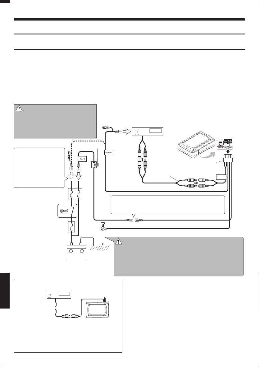
Ligações
Ligação de entrada RCA
Ligue o subwoofer à saída do subwoofer (saída sem atenuador variável) ou às tomadas RCA da saída frontal da
unidade central.
Notas:
• Leia os manuais de instruções dos componentes ligados, tais como a unidade central, assim como o presente manual de instruções.
• Adquira um cabo RCA que esteja disponível no mercado em separado.
• Quando a unidade central possuir um DSP, ligue o subwoofer à saída do subwoofer (saída sem atenuador variável) ou às tomadas RCA da saída frontal. Não ligue às tomadas RCA da saída traseira, pois o pois o efeito de reprodução de baixa frequência poderá ser atenuado devido ao efeito do DSP.
Exemplos
■
A seguir é apresentada uma ligação típica para uma reprodução sonora correcta num automóvel. Ligue o sistema seguindo o
exemplo.
Precaução:
Não distribua os cabos em padrões nos
quais possam ficar presos por uma peça do
veículo ou possam ficar danificados. Caso
contrário, pode ocorrer um choque eléctrico ou um incêndio devido a curto-circuitos.
Unidade central
(SUB WOOFER OUT,
Saída sem atenuador variável)
KSC-SW11
Se não existir um terminal
de controlo de alimentação na uni dade centra l,
ligue o cabo azul/branco à
linha do acessório (linha da
posição ACC do interruptor
da chave de ignição).
Caixa de fusível
de automóvel
Interruptor da
chave de ignição
Caixa de fusível de
automóvel
(Fusível principal)
Unidade central
Fusível 10A
※
Bateria
PORTUGUÊS
Cabo RCA
(Vendido
separadamente)
Quando a saída da unidade central for um único cabo
RCA, utilize um cabo RCA que converta a saída em duas
tomadas RCA conforme acima apresentado. A saída do
subwoofer será dividida em duas se não for utilizado o
cabo de conversão.
KSC-SW11
10-pino cabo d o conector
2
Cabo RCA
(Vendido separadamente)
Azul/Branco
Se escutar um zumbido a partir dos altifalantes quando o
motor estiver em funcionamento, ligue um filtro de ruído da
linha (disponível no mercado) à ficha de alimentação.
Amarelo Amarelo
Preto
Precaução:
GND
※
Ligue directamente o terminal de massa do cabo da ficha preta
com um parafuso a uma peça de metal não pintada do veículo.
Ligar a alimentação (ON) sem ligar este terminal poderá danificar o
sistema sonoro. Certifique-se de que o liga.
Para além disso, os painéis de metal pintados, etc., não estão liga-
dos à massa e não funcionam correctamente. Tenha cuidado.
LINE IN
20
Português
Page 51

Instalação
Antes de fixar o altifalante na respectiva posição, certifique-se de que verifica o som enquanto está preliminarmente ligado.
Precaução:
• Ao efectuar um orifício sob o banco, no interior da bagageira ou em qualquer outro ponto do veículo, verifique se não existe qualquer perigo no lado oposto, tal como o depósito de gasolina, tubo dos travões ou cablagem e tenha cuidado para
não provocar riscos ou outros danos.
• Instale num local onde não condicione a condução, a saída do veículo e o movimento no interior do habitáculo do veículo.
• Fixe firmemente o produto de modo a que não se moda devido a vibrações ou impactos durante a condução.
Fixar o cabo no sítio
■
Parafuso para má quina x 2
8
Suporte B
5
Controlo remoto
10-pino cabo d o conector
2
Fixação do subwoofer
■
1
O subwoofer pode ser fixado de duas formas. Seleccione a posição de fixação ideal do suporte A 4 de acordo com a localização de instalação do subwoofer.
Método de xação A Método de xação B
Suporte A
11
Parafuso para má quina x 4
7
Suporte A x 2
4
Fixe firmemente os suportes A 4 à unidade do altifalante utilizando os parafusos para máquina 7. Tenha
cuidado de modo a que os cabos ligados não permaneçam entre a unidade do altifalante e os suportes A 4.
22
4
Precaução:
Esta parte fica ligeiramente mais quente do
que as outras partes
porque funciona como
radiador do calor gerado
pelo amplificador.
Torneira parafusos x 4
6
Ligue o 10-pino cabo do conector 2 e o controlo remoto 1 à unidade do altifalante.
Fixe os cabos à unidade do altifalante com o suporte
B 5 e fixe no sítio com os parafusos para máquina 8.
Proibição!
Fixe o cabo de modo a que não
fique projectado a partir da
parte lateral da unidade do altifalante.
Suporte A
4
Parafuso para má quina x 4
7
Suporte A x 2
4
Precaução:
Esta parte fica ligeiramente mais quente do
que as outras partes
porque funciona como
radiador do calor gerado
pelo amplificador.
Fixe firmemente os suportes A 4 à unidade do altifalante utilizando os parafusos para máquina 7. Tenha
cuidado de modo a que os cabos ligados não permaneçam entre a unidade do altifalante e os suportes A 4.
Torneira parafusos x 4
6
PORTUGUÊS
Perfure quatro orifícios guia
para parafusos de ø 3,6 mm.
Perfure os orifícios guia para parafusos de ø 3,6 mm
na secção da placa de metal do veículo e fixe a unidade do altifalante ao veículo utilizando os parafusos
torneira 6.
Perfure quatro orifícios
guia para parafusos de
ø 3,6 mm.
Perfure os orifícios guia para parafusos de ø 3,6 mm
na secção da placa de metal do veículo e fixe a unidade do altifalante ao veículo utilizando os parafusos
torneira 6.
Português
21
Page 52

Instalação
Instalação da unidade do controlo remoto
■
Instale a unidade do controlo remoto no veículo utilizando o fixador de encaixe fornecido.
Controlo remoto
1
(Painel posterior)
Veícu lo
Fixador de encaixe
9
(Superfície mais
rígida)
Fixador de encaixe
9
(Superfície mais suave)
Substituição do fusível
Substitua por um fusível com
a capacidade especificada.
Remoção
■
Fusíve l
Abra a tampa.
1
Agarra o fusível e puxar para cima.
2
Precaução: Certifique-se de que o substitui por um com a mesma capacidade (amperagem)
Tam pa
Apoio de fusível
conforme apresentado no fusível. Este produto tem a especificação 10A.
Operação
Nome de cada peça (Controlo remoto)
■
Iluminação
Quando a alimentaç ão está ligada
(ON), a luz acende-se.
Controle VOLUME
(Manípulo de controlo da
sensibilidade de entrada)
Controle FREQUENCY
(Manípulo de control o da frequência
de corte)
Interruptor PHASE
(Interruptor de selecção de fase)
PORTUGUÊS
Precaução:
Instale a unidade do controlo remoto numa posição que
não condicione as operações de condução.
Evite instalar num local sujeito a luz solar directa ou vento
quente directo proveniente do aquecedor. Caso contrário,
o produto poderá ficar degradado e poderá ocorrer o perigo de incêndio.
Remova a sujidade da posição de instalação antes de instalar o fixador de encaixe.
Inserção
■
Substituição
do fusível 10 A
Introduza cuidadosamente o fusível no suporte de fu-
1
síveis e introduza-o por completo utilizando o dedo.
Feche a tampa.
2
Ajuste do som
■
A
0
1
(Operação com o controlo remoto)
Rode o manípulo de controlo FREQUENCY (Fre-
1
quência) para ajustar a frequência de corte (as frequências superiores a esta são cortadas).
Rode o manípulo de controlo FREQUENCY (Frequência) para
ajustar o equilíbrio entre os graves dos altifalantes traseiros e os
graves desta unidade conforme pretendido.
Nível de pressão
sonora
Ajuste a fase de baixa frequência.
2
O tom de baixa frequência poderá variar dependendo da posição da unidade, da sua or ientação ou da frequência de alternância. Pode ser ajustado alterando a posição do interruptor PHASE
(Fase). Coloque este interruptor na posição que corresponda às
suas preferências. [0°] indica a fase normal e [180°] indica a fase
inversa.
50 Hz
125 Hz
Baixo Elevado
Frequ ência
Baixo Elevado
O som é emitido mesmo quando a unidade do controlo remoto não está ligada, mas as operações descritas
nesta secção não estão disponíveis.
Nesse caso, o volume, frequência e corte e fase são de nidos de acordos com as condições padrão predeterminadas, com as quais a frequência de corte é de 125
Hz e a fase de 0º (positiva).
Português
22
Rode o manípulo de controlo VOLUME para ajus-
3
tar as baixas frequências de acordo com o nível
pretendido.
Para diminuir
o volume
Para aumentar
o volume
Page 53

Guia de resolução de problemas
Normalmente o que parece ser uma avaria está relacionado com um erro por parte do utilizador. Antes de solicitar assistência técnica,
consulte a seguinte tab ela.
Problema Causa Remédio
A alimenta ção não
consegue s er ligada (a
iluminação não acende).
Sem som
O sonoro é baix o.
A qualidad e sonora é
má (o som é distor cido).
O som não é natu ral.
O controlo r emoto não
funciona.
As iluminações na unidade do controlo remoto não se ace ndem.
• O fusível está queimado. • Verifique a polaridade (+)/(-) do cabo de alimen-
• O pino da fonte de alimentação (amarelo) do cabo
de ligação de 10 pinos não está ligado.
• O pino de controlo da alimentação (azul/branco)
do cabo de ligação de 10 pinos não está ligado.
• O pino de massa (preto) do cabo de ligação de 10
pinos não está ligado.
• O conector de 10 pinos não está completamente
ligado.
• O cabo negativo (-) da bateria do automóvel está
desligado.
• O atenuador da unidad e central está definido para
ON (Ligado).
• O controlo VOLUME está definido para a posição
MIN (Mínimo).
• Os ca bo s do altifala nte estão i ncorrectament e
ligados.
• Os termi nais de ligação est ão incorre ct amente
ligados.
• O nível de entrada es tá definido para baixo. • Rode o manípulo de controlo VOLUME e defina
• Os termi nais de ligação est ão incorre ct amente
ligados.
• O nível de entrada es tá definido para alto. • Rode o manípulo de controlo VOLUME e defina
• Os cabos do altifalante estão ligados com a polaridade positiva (+)/negativa (-) errada.
• O pino de massa (preto) do cabo de ligação de 10
pinos possui um contac to insuficiente.
• O cabo do controlo remoto está desligado. • Ligue o cabo ao terminal REMOTE (Remoto).
tação e se os cabos não estão em curto-circuito
e, em seguida, substitua o fusível por um com a
mesma capacidade nominal.
• Volte a ligar correc tamente os cabos consultando o exemplo de ligaç ão (na página 19, 20).
• Ligu e co rr ect am ente o cabo c on su lt and o o
exemplo de ligação (na página 19, 20).
• Ligue o terminal de massa à secção metálica do
veículo (superfície não revestida) apertando-o
firmemente.
• Introduza totalmente o co nector.
• Verifique as ligações de todos os cabos e, em
seguida, ligue o cabo (-) à bateria.
• Verifique as ligações de todos os cabos e, em
seguida, ligue o cabo (-) à bateria.
• Coloque o atenuador na posição OFF (Desligado).
• Aumente o volume para um nível adequado (na
página 22).
• Ligu e co rr ect am ente o cabo c on su lt and o o
exemplo de ligação (na página 19).
• Introduza totalmente os conectores ou tomadas nos terminais.
o nível de entrada para um nível adequa do.
• Ligue o cabo ao terminal REMOTE (Remoto).
• Verifique se o cabo RCA está ligado correctamente.
o nível de entrada para um nível adequa do.
• Ligu e co rr ect am ente o cabo c on su lt and o o
exemplo de ligação (na página 19, 20).
• Ligue o terminal de massa à secção metálica do
veículo (superfície não revestida) apertando-o
firmemente.
• Introduza totalmente o co nector.
Especificações
As especificações podem s er alteradas sem prévia notificaç ão.
Saída máx ima ....................................................................150 W
Resposta d e frequência ...................................... 35 Hz - 150 Hz
Frequênci a de corte ............................................ 50 Hz - 125 Hz
Fase ...................................................................................0˚, 180˚
Sensibilidade/impedância de entrada
LINE IN .............................................................. 50 mV / 22 kΩ
Alimenta ção .... 14,4 V (Escala de funci onamento 11 V - 16 V)
Consumo corr ente máximo .............................................. 8, 5 A
Capacida de do fusível .........................................................10 A
Sensibil idade .................................................. 110 dB (No carro)
Dimensõ es externas .......................... Largura: 2 80 mm
Altura: 70 mm
Profundidad e: 190 mm
Peso (net) ...........................................................................2,8 kg
Português
PORTUGUÊS
23
Page 54

ВАЖНЫЕ ИНСТРУКЦИИ ПО БЕЗОПАСНОСТИ
Внимание: Для обеспечения безопасной работы, внимательно изучите данную страницу.
• Перед монтажом или соединением проводов, др., обязательно удалите провод от минусового терминала батарейки. (В противном случае, это может привести к короткому замыканию или пожару.)
• При удлинении проводов запуска, батареек, или заземления, обязательно используйте провода подвижного типа
или д ругие п ровод а на 0,75мм2 (AWG18) или более во
избежание износа и повреждения покрытия.
•
Во избежание короткого замыкания, никогда не кладите
или оставляйте любые металлические предметы (например,
монеты или металлические инструменты) внутри колонки.
•
В случае образования дыма или неестественного запаха от
данного аппарата, немедленно переключите питание на OFF.
После этого, пожалуйста, по возможности быстро свяжитесь
с дилером или ближайшей станцией техобслуживания.
ОТКЛЮЧИТЕ ПИТАНИЕ!
• Подключите колонку к источнику 12В постоянного тока, с
заземлением отрицательного полюса.
• Не пытайтесь открыть или модифицировать аппарат, так
как это может привести к пожару или поломке.
• После извлечения аппарата из полиэтиленового пакета,
обязательно выкиньте полиэтиленовый пакет, во избежание попадания в руки детей. В ином случае, они могут
начать играть с пакетом, что может привести к удушью.
ВниманиеВнимание
• Установка и соединение проводов изделия требует
специальных знаний и опыта. Для обеспечения безопасности, установка и соединения должны производиться
дилером или специалистом.
• Не устанавливайте колонку в местах, подвергающихся
прям ому п опаданию солнечных л учей или излишнему
нагреванию или влажности.
• Не устанавливайте колонки в местах, где они могут подвергнуться попаданию воды или влаги.
• Не устанавливайте колонки в неустойчивых местах, или
местах, где легко образуется пыль.
При сгорании предохранителя, после проверки того, не
•
подвергнулся ли кабель короткому замыканию, обязательно замените на предохранитель указанного размера (амперной нагрузки), как показано в блоке предохранителей.
(Использование предохранителей, кроме предохраните-
лей указанного размера, может привести к пожару.)
Проверьте дисплей!
Для замены предохранителя, смотрите инструкцию по
экслуатации к автомобилю.
• Во избежание короткого замыкания при замене предохранителя, сначала отсоедините жгут проводов.
• При чистке колонки, не используйте бензин, керосин, или
любой тип растворителя. При очистке, протирайте мягкой, сухой тканью.
• Подключайте провода колонок к соответствующим разъемам колонок по-отдельности. Общее использование
отрицательного провода колонки или заземление проводов колонки на металлический корпус машины может
привести к поломке данного аппарата.
• При создании отверстия под сиденьем, вну три багажника,
или еще где-либо на автомобиле, проверьте, нет-ли ничего опасного на противоположной стороне, как бензобак,
тормозной шланг, или жгут проводов, и будьте внимательны во избежание царапин или других повреждений.
• Для монтажа провода заземления, не прикрепляйте провод к подушке безопасности, системе рулевого управления или тормозной м агистрали или другим важ ным
РУССКИЙ
болтам или гайкам устройства безопасности.
(Может привести к авариям.)
Русский
24
ПРЕДУПРЕЖДЕНИЕПРЕДУПРЕЖДЕНИЕ
• При монтаже, обязательно устанавливайте в местах, не
мешающих вождению, или где могут быть опасны для пассажиров во время экстренного торможения, др.
(Причина травм или аварий.)
• После установки данного аппарата, убедитесь, что электрооборудование, например, тормозные лампы, поворотные сигналы и дворники работают как обычно.
• Водитель должен всегда остановить автомобиль в безопасном месте перед выполнением следующего действия.
– Управление пультом ДУ
• Не используйте данное изделие для других целей, кроме
как установки на автомобиле.
Декларация соответствия относительно Директивы EMC 2014/30/EU
Декларация соответствия относительно Директивы RoHS 2011/65/EU
Производитель:
JVC KENWOOD Corporation
3-12 Moriya-cho, Kanagawa-ku, Yokohama-shi,
Kanagawa, 221-0022, ЯПОНИЯ
Представительство в ЕС:
JVCKENWOOD Europe B.V.
Amsterdamseweg 37, 1422 AC Uithoorn, НИДЕРЛАНДЫ
Дата изготовления (месяц/год) находит-
ся на этикетке устройства.
В соответствии с Законом Российской Федерации “О
защите прав потребителей” срок службы (годности)
данного товара “по истечении которого он может
представлять опасность для жизни, здоровья потребителя, причинять вред его имуществу или окружающей
среде” составляет семь (7) лет со дня производства.
Дополнительные косметические материалы к данному
товару, поставляемые вместе с ним, могут храниться в
течение двух (2) лет со дня его производства.
Срок службы (годности), кроме срока хранения дополнительных косметических материалов, упомянутых
в предыдущих двух пунктах, не затрагивает никаких
других прав потребителя, в частности, гарантийного
обслуживания KENWOOD, которое он может получить
в соответствии с законом о правах потребителя или
других законов, связанных с ним.
Условия хранения:
Температура: от –30°C до +85°C
Влажность: от 0% до 90%
Информация о продукции
Производитель: ДжейВиСи Кенвуд Корпорейшн
3-12, Морийячо, Канагава-ку, Йокохама-ши, Канагава 221-0022, Япония
Активный сабвуфер
Модели: KSC-SW11
Сертификату Соответствия RU C-JP.AГ21.B.03434
Дата выдачи Сертификата Соответствия 18.09.2018
Сертификат Соответствия действителен до 17.09.2023
Соответствует требованиям
нормативных документов
Завод-изготовитель Toptone Acoustics (Suzhou) Co., Ltd.
ТР ТС 020/2011 «Электромагнитная
совместимость технических средств»
No.161, Jin Feng Road, Suzhou New
District, Jiangsu, 215011, China (Китай)
Page 55

Поставляющиеся детали
№ Название детали Внешняя форма Количество № Название детали Внешняя форма Количество
Пульт ДУ
1
(5 м)
10-контактный соеди-
2
нительный кабель (5 м)
Шнур колонка
3
(4,3 м )
Крепление A 2
4
Крепление B 1
5
1
1
1
Нарезной винт
6
(ø 5 × 16 мм)
Крепежный винт
7
(M4 × 5 мм)
Крепежный винт
8
(M3 × 8 мм)
Застежка-липучка
(Двусторонний клей/
9
для пульта ДУ)
4
4
2
1
Подключение
Внимание:
Перед соединением, обязательно удалите провод с отрицательного терминала батарейки. После завершения всех
соединений, снова убедитесь в правильности соединений. После проверки, подключите провод от отрицательного
терминала батарейки.
Терминалы сабвуфераТерминалы сабвуфера
■
Терминал POWER/SPEAK ER INPUT
Тер мин ал R EMOT E
Подключение пульта ДУПодключение пульта ДУ
■
Пульт ДУ
1
Подключайте
фиксатором гнезда
пульта ДУ вниз.
Фиксатор
Примечания:
• Обязательно подключите поставляемый пульт ДУ.
• Если кабель подключен неправильно, подсветка на пульте ДУ не высвечивается.
• Не подключайте соединитель пульта ДУ верхней стороной вниз или с применением силы. В противном случае, это может привести к сбоям.
Высвечивается синим.
При включении
питания высвечивается
подсветка.
Русский
РУССКИЙ
25
Page 56
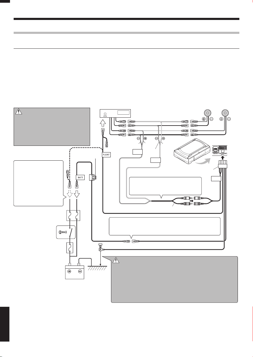
Подключение
Подключение входа колонки
Подключите сабвуфер к выходным кабелям фронтальной колонки или задней колонки на центральном
блоке.
Примечания:
• Изучите инструкции по эксплуатации к подключенным компонентам, как центральный блок, а также данную инструкцию по эксплуатации.
• Когда центральный блок оборудован функцией DSP, не подключайте к выходу задней колонки, так как эффект низкочастотного воспроизведения может быть ослаблен эффектом DSP.
ПримерыПримеры
■
На следу ющей схеме отобр ажено типичное под ключение дл я эффективног о прослушиван ия стереофонич еской системы автомо биля. Подключ ите систему с учет ом примера.
Центральный блок
Внимание:
Не проводите кабели в направлениях,
где они могут быть задеты деталью автомобиля или могут быть повреждены.
В противном случае это может вызвать
электрошок или пожар по причине короткого замыкания.
Если отсутс твует терминал управления
питанием на центральном блоке, подключите
синий/белый провода к
дополнительной линии
(линия на позиции АСС
переключателя ключа
зажигания).
Блок предохранителей
машины
Переключатель
ключа зажигания
Блок предохранителей
машины (Основной
предохранитель)
Предохранитель
Аккумулятор
10А
※
Серый/Черный
Синий/Белый
При зудящем шуме от колонок при работающем двигателе, прикрепите фильтр линейного шума (продается отдельно) на провод питания.
Желтый Желтый
Черный
GND
※
Также, окрашенные металлические панели, др., не заземлены, и
Белый
Серый
SP.R
Белый/
INPUT
Черный
SP.L
INPUT
10-контактный
2
соединительный кабель
Не сгибайте часть кабеля колонки с
виниловым покрытием. В противном
случае это может привести к сбоям.
Шнур колонка
3
Внимание:
Подключите терминал заземления черного провода напрямую
через винт к неокрашенной металлической части автомобиля.
При установке питания на ON без подключения данного терминала может привести к поломке стереофонической системы.
Обязательно подк лючите его.
не будут срабатывать соответствующим образом. Будьте внимательны.
Фронтальная или
задняя колонка
Влево Вправо
KSC-SW11
LINE IN
РУССКИЙ
26
Русский
Page 57

Подключение входа RCA
Подключите сабвуфер к выходу сабвуфера (нерегулируемый выход) или гнездам RCA для фронтального
выхода от центрального блока.
Примечания:
• Изучите инструкции по эксплуатации к подключенным компонентам, как центральный блок, а также данную инструкцию по эксплуатации.
• Пожалуйста, приобретите отдельно продающийся кабель RCA.
• Когда центральный блок содержит DSP, подключите сабвуфер к выходу сабвуфера (нерегулируемый выход) или гнездам
RCA для фронтального выхода. Не подключайте гнезда RCA для заднего выхода, так как эффект низкочастотный воспроизведения может ослабевать из-за эффекта DSP.
ПримерыПримеры
■
На следующей схеме отображено типичное подключение для эффективного прослушивания стереофонической системы автомо биля. Подключ ите систему с учет ом примера.
Внимание:
Не проводите кабели в направлениях, где
они могут быть задеты деталью автомобиля
или могут быть повреждены. В противном
случае это может вызвать электрошок или
пожар по причине короткого замыкания.
Если отсутс твует терминал управления
питанием на центральном блоке, подключите
синий/белый провода к
дополнительной линии
(линия на позиции АСС
переключателя ключа
зажигания).
Блок предохранителей
машины
Переключатель
ключа зажигания
Блок предохранителей
машины (Основной
предохранитель)
Предохранитель
Аккумулятор
10А
При зудящем шуме от колонок при работающем двигателе, прикрепите фильтр линейного шума (продается отдельно) на провод питания.
※
GND
Центральный блок
(SUB WOOFER OUT,
Нерегулируемый выход)
KSC-SW11
10-контактный
2
Кабель RCA
(Отдельно продающиес я детали)
Синий/Белый
Желтый Желтый
Черный
соединительный кабель
LINE IN
Внимание:
※
Подключите терминал заземления черного провода напрямую
через винт к неокрашенной металлической части автомобиля.
При установке питания на ON без подключения данного терминала может привести к поломке стереофонической системы.
Обязательно подк лючите его.
Также, окрашенные металлические панели, др., не заземлены, и
не будут срабатывать соответствующим образом. Будьте внимательны.
Центральный блок
Кабель RCA
(Отдельно продающиес я
детали)
KSC-SW11
Если на центральном блоке имеется одно гнездо RCA, используйте кабель RCA, преобразующий выхода на два гнезда RCA как показано выше.
Выход сабвуфера будет уменьшен наполовину, если не используется
преобразующий кабель.
Русский
РУССКИЙ
27
Page 58

Установка
Перед установкой колонки на мес те установки, временно подк лючив ее, убедитесь, что звучани е выводится.
Внимание:
• При создании отверстия под сиденьем, внутри багажника, или еще где-либо на автомобиле, проверьте, нет-ли ничего
опасного на противоположной стороне, как бензобак, тормозной шланг, или жгут проводов, и будьте внимательны во
избежание царапин или других повреж дений.
• Устанавливайте в местах, где не будет создаваться препятствий вождению, входу или выходу из автомобиля, и перемещению внутри салона автомобиля.
• Надежно закрепите изделие, чтобы оно не могло быть сдвинуто из-за вибраций и толчков во время вождения.
Закрепление кабеля на местеЗакрепление кабеля на месте
■
Крепежный вин т x 2
8
Крепление B
5
Пульт ДУ
10-контактный соединительный кабель
2
Закрепление сабвуфераЗакрепление сабвуфера
■
1
Сабвуфер можно закрепить двумя способами. Выберите оптимальную позицию установки для крепления A 4 в соответствии с местом установки сабвуфера.
Способ закрепления A Способ закрепления B
Крепление A
11
Крепежный вин т x 4
7
Крепление A x 2
4
Надежно прикрепите крепления A 4 к колонке
с помощью крепеж ных винтов 7. Соблюдайте
предосторожность, и не давайте подключенным
кабелям оставаться между колонкой и креплениями A 4.
22
4
Внимание:
Данная часть слегка нагревается по сравнению
с друг ими частями, так
как она выполняет функцию излучателя тепла от
усилителя.
Нарезной винт x 4
6
Подключите 10-контактный соединительный кабель 2 и пульт ДУ 1 к колонке.
Прикрепите кабели к колонке с помощью крепления B 5 и закрепите с помощью крепежных винтов 8
.
Запрещено!
Закрепите кабель таким образом, чтобы он не выступал
за пределы блока колонки.
Крепление A
4
Крепежный вин т x 4
7
Крепление A x 2
4
Внимание:
Данная часть слегка нагревается по сравнению
с друг ими частями, так
как она выполняет функцию излучателя тепла от
усилителя.
Надежно прикрепите крепления A 4 к колонке
с помощью крепеж ных винтов 7. Соблюдайте
предосторожность, и не давайте подключенным
кабелям оставаться между колонкой и креплениями A 4.
Нарезной винт x 4
6
Пробурите четыре
направляющих отверстий
Пробурите направляющие отверстия для ø3,6 мм
РУССКИЙ
винтов на участке листового металла автомобиля,
для ø3,6 мм винтов.
и с помощью нарезной винт 6 прикрепите колонку к автомобилю.
Русский
28
Пробурите четыре
направляющих отверстий
для ø3,6 мм винтов.
Пробурите направляющие отверстия для ø3,6 мм
винтов на участке листового металла автомобиля,
и с помощью нарезной винт 6 прикрепите колонку к автомобилю.
Page 59

Установка пульта ДУУстановка пульта ДУ
■
Установ ит е пу льт ДУ на автомобиле с пом ощ ью
прилагаемой застежки-липучки.
Пульт ДУ
1
(Задняя панель)
Автомобиль
Застежка-липучка
9
(Твердая
поверхность)
Застежка-липучка
9
(Мягкая
поверхность)
Замена предохранителя
Заменяйте на предохранитель указанной мощности.
Извлечение
■
Предохранитель
Патрон
Откройте крышку.
1
Захватите плоскогубцами и вытяните.
2
предохранителя
Крышка
Внимание:
Обязательно замените на предохранитель с одинаковой мощностью (амперной
нагрузкой) как отображено на предохранителе. Нагрузка данного изделия - 10A.
Установка
■
Замена
предохранителя
на 10 А
Аккуратно вставьте предохранитель в патрон
1
Закройте крышку.
2
Управление
Название каждого органа управленияНазвание каждого органа управления
■
(Пульт ДУ) (Пульт ДУ)
Подсветка
При включении питания
высвечивается подсветка.
Ручка управления VOLUME
(Ручка управ ления
чувствительностью приема)
Ручка управления FREQUENCY
(Ручка управ ления частотой
отсечки)
Переключатель PHA SE
(Переключатель селектора фазы)
Внимание:
Устанавливайте пульт ДУ в местах, где он не будет мешать вождению.
Избегай те его установки в местах, подвер гающихся
прямому попаданию солнечных лучей или прямому
попаданию горячего воздуха от обогревателя. В ином
случае, изделие может ух удшиться, и также педставлять риск пожара.
Перед наклеиванием застежки-липучки начисто
протрите позицию установки.
A
0
1
предохранителя, и надавите до конца пальцем.
Регулировка звучания Регулировка звучания
■
(Управление от пульта ДУ) (Управление от пульта ДУ)
Поворачивая ручку управления FREQUENCY,
1
отрегулируйте частоту отсечки (частоты выше
данной частоты будут срезаться).
Поворачивайте ручку управления FREQUENCY для
регулировки нужного баланса басов задних колонок и басов
от данного аппарата.
Уровень
звукового
давления
Отрегулируйте низкочастотную фазу.
2
Низкочастотный тональный сигнал может изменяться в зависимости от расположения аппарата, его направления, или
частоты оборота. Он может регулироваться пу тем переключения позиции переключателя PHASE. Установите данный
переключате ль на любую нужную позицию.
[[0°] обозначает обычную фазу и [180°] обозначает обратную
фазу.
50 Гц
125 Гц
Низкая Высокая
Частота
Низкая Высокая
Звучание выводится даже если пульт ДУ не подключен, но тогда описанные в данном разделе операции становятся недоступными.
В таком случае уровень громкости, частота отсечки
и фаза устанавливаются на предварительно установленные настройки по умолчанию, при которых
частота отсечки 125 Гц и фаза 0º (положительная).
Поворачивая ручку управления VOLUME, отре-
3
гулируйте низкие частоты до ну жного уровня.
Понижение
уровня громкости
Повышение
уровня громкости
Русский
РУССКИЙ
29
Page 60

Руководство по возможным неисправностям
и способам их устранения
Часто ошибка в использовании принимается за неисправно сть. Перед обращением в мастер скую, пожалуйста, изучите с ледующую таблицу.
Неисправность Причина Способ устранения
Невозможно включить
питание (по дсветка не
высвечивается).
Отсу тствует звук.
Малый ур овень громкости.
Плохое качество звучания
(звучание искажено).
Неестественное звучание.
Пульт ДУ не работ ает.
Не высвечиваются подсветки на пульте ДУ.
• Обгорел предохранитель. • Проверьте полярность (+)/(-) силового
• Не подключен контакт (желтый) энергообеспечения на 10-контактном соединительном кабеле.
• Не подключен контакт (синий/белый)
управления питанием на 10-контактном
соединительном кабел е.
• Не подключен контакт (черный) зазем ления
на 10-контактном соединительном кабеле.
• Неполнос тью подк лю че н 10-кон тактный
соединитель.
• Отсоединен отрицательный (-) кабель аккумулятора автомобиля.
• Аттенюатор цен тра льного блока ус тан овлен на ON.
• Ручка VOLUME установлена на позицию
MIN.
• Ненадежно подключены кабели колонок. • Правильно подключите кабели, используя
• Ненаде жно под ключены терм иналы п одключения.
• Установлен низкий у ровень входа. • Поворачива йте ручку у правления VOLUME
• Ненаде жно под ключены терм иналы п одключения.
• Установлен высокий у ровень входа. • Поворачивайте ручку управления VOLUME
• Кабели колонок подключены с неправильной положительной(+)/отрицательной (-)
полярностью.
• Не подключен контакт (черный) зазем ления
на 10-контактном соединительном кабеле.
• Не подключен к абель пульта ДУ. • Подключите кабель в терминал REMOTE.
кабеля, а также, что кабели не замкнуты коротко, затем замените на предохранитель с
установленной мощностью.
• Заново подключите кабели соответствующим образом, используя пример подключения (на стр. 26, 27).
• Подключите кабель соответствующим образом, используя пример подключения (на
стр. 26, 27).
• Закрепите терминал заземления на металлической части автомобиля (неокрашенной
поверхности) и надежно прикру тите его.
• Полностью вст авьте соединитель.
• Проверьте подк лючения всех кабелей, затем подключите к абель (-) к аккумулятору.
• Проверьте подк лючения всех кабелей, затем подключите к абель (-) к аккумулятору.
• Переключите ат тенюатор на OFF.
• Поднимит е ур ов ень громкос ти до оптимального уровня (на стр. 29).
пример подк лючения (на стр. 26).
• Полностью вставьте соединители или гнезда в терминалы.
и установите оптимальный уровень входа.
• Подключите кабель в термина л REMOTE.
• Убедитесь, что кабель RCA подключен правильно.
и установите оптимальный уровень входа.
• Подключите кабель соответствующим образом, используя пример подключения (на
стр. 26, 27).
• Закрепите терминал заземления на металлической части автомобиля (неокрашенной
поверхности) и надежно прикру тите его.
• Полностью вст авьте соединитель.
Технические характеристики
Следующи е данные и дизайн мо гут изменяться без уведомлени я.
Максима льный выход .............................................. 150 Ватт
Частот ная характерис тика ...................................35 - 150 Гц
Частота о тсечки .......................................................50 - 125 Гц
Фаза .................................................................................0˚, 180˚
Чувствительность/импеданс входа
LINE IN ............................................................... 50 мВ / 22 кΩ
РУССКИЙ
Русский
30
Питание ........................................... 14,4 В постоя нного тока
(рабочий ди апазон 11 - 16 В)
Макс
Мощнос ть предохранител я ............................................. 10 A
Чувств ительность .............................110 дБ (В автомо биле)
Наружн ие размеры ...................................Шир ина: 280 мм
Высота: 70 мм
Глубина: 190 мм
Вес (нетт о) .........................................................................2, 8 кг
имально е энергопотреб ление ............................. 8 ,5 A
 Loading...