

Kenwood KSC-SW01 User Manual

KSC-SW01
POWERED ENCLOSED SUBWOOFER
INSTRUCTION MANUAL
CAISSON D’EXTRÊME GRAVE AMPLIFIÉ
MODE D'EMPLOI
GEKAPSELTER SUBWOOFER MIT VERSTÄRKER
BEDIENUNGSANLEITUNG
SUBWOOFER MET SPANNINGSCIRCUIT
GEBRUIKSAANWIJZING
SUBWOOFER CON AMPLIFICATORE E CASSA
ISTRUZIONI PER L'USO
ALTAVOZ DE SUBGRAVES CON CERRADO ALIMENTACION
MANUAL DE INSTRUCCIONES
SUBWOOFER COM AMPLIFICADOR E CAIXA
MANUAL DE INSTRUÇÕES
ENGLISH FRANÇAIS DEUTSCH NEDERLANDS ITALIANO ESPAÑOL PORTUGUÊS
B61-1344-00/00 (W) KW
©
IMPORTANT SAFETY INSTRUCTIONS
Caution: Read this page carefully to ensure safe operation.
WARNING
• Before mounting or wiring etc., be sure to remove the
wire from the battery minus terminal.
(Not doing so can cause shorts or fires.)
• When extending the ignition, battery, or ground wires,
make sure to use automotive-grade wires or other wires
with a 0.75mm
ration and damage to the wore coating.
• To prevent a short circuit, never put or leave any metallic
ENGLISH
objects (such as coins or metal tools) inside the speaker.
• In the event the unit generates smoke or abnormal smell,
immediate ly switch th e power O FF. After this , please
contact your dealer or nearest service station as soon as
possible.
POWER OFF!
• Connect the illumination lamp-equipped speakers to DC
12V, negative ground.
• Do not attempt to open or modify the unit, for this could
cause fire hazard or malfunction.
• After taking the unit out of the polyethylene bag, be sure
to dispose of the polyethylene bag out of the reach of
children. Otherwise, they may play with the bag, which
could cause hazard of suffocation.
2
(AWG18) or more to prevent wire deterio-
CAUTION
• Installation and wiring of the product requires expert skill
and experience. To ensure safet y, be sure to have your
dealer or specialist perform the installation and wiring.
• Do not install the speaker in a spot exposed to direct sunlight or excessive heat or humidity.
• Do not install the speakers in locations which may be
subject to water or moisture.
• Do not install the speakers in unstable locations or locations subject to dust.
• If the fuse blows, after checking to see if the wiring cord
has shorted, be sure to replace with the stipulated size
(amperage) fuse as displayed on the fuse box.
(Using fuses other th an th e stipu lated si ze can cause
fires.)
Check the display!
To replace the fuse, refer to the vehicle instruction manu-
al.
• To prevent a short circuit when replacing a fuse, disconnect the wiring harness at first.
• Do not use gasoline, naphtha, or any type of solvent to
clean the speaker. Clean by wiping with a soft, dry cloth.
• Connect the speaker wires to appropriate speaker connect or s se pa ra tely. Sharing the negative wir e of t he
speaker or grounding speaker wires to the metal body of
the car can cause this unit to fail.
• Do not connect cables and leads to both RCA cord input
jacks and the speaker input terminals simultaneously, for
this may cause malfunction or damage.
• When making a hole under a seat, inside the trunk, or
somewhere else in the vehicle, check that there is nothing hazardous on the opposite side such as a gasoline
tank, brake pipe; or wiring harness, and be careful not to
cause scratches or other damage.
• For ground wire mounting, do not fasten the wire to
an airbag, steering or brake line system or other critical
safety unit bolts or nut.
(Can cause accidents.)
English
2
• When mounting, be sure to mount in a place that will not
interfere with driving or be dangerous to passengers during sudden braking etc.
(Cause of injury or accidents.)
• After installing the unit, check to make sure that electrical
equipment such as the brake lamps, turn signal lamps
and windshield wipers operate normally.
• The driver should always stop the vehicle in a safe place
before performing the following action.
– Remote control operation
• Do not use the product for purposes other than on-board
mounting.
Information on Disposal of Old Electrical
and Electronic Equipment (applicable for
EU countries that have adopted separate
waste collection systems)
Products with the symbol (crossed-out
wheeled bin) cannot be disposed as household waste.
Old electrical and electronic equipment should be
recycled at a facility capable of handling these items
and their waste by products.
Contact your local authority for details in locating a
recycle facility nearest to you.
Prop er re cyclin g and waste disp osal will help conserve resources whilst preventing detrimental effects
on our health and the environment.
Declaration of Conformity with
regard to the EMC Directive
2004/108/EC
Manufacturer:
Kenwood Corporation
2967-3 Ishikawa-machi, Hachioji-shi, Tokyo,
192- 8525 J apa n
EU Representative’s:
Kenwood Electronics Europe BV
Amsterdamseweg 37, 1422 AC UITHOORN,
The Netherlands
For Turkey
Bu ürün 26891sayılı Resmi Gazete’de yayımlanan Elektrikli ve
Elektronik Eşyalarda Bazı Zararlı Maddelerin
Kullanımının Sınırlandırılmasına Dair Yönetmeliğe uygun
olarak üretilmiştir.
This produc t complies with Directive, Number 26891 regarding "REGULATION ON THE RESTRICTION OF THE USE
OF CERTAIN HAZARDOUS SUBSTANCES IN ELECTRICAL AND
ELECTRONIC EQUIPMENT".
Parts included
No. Part Name Outside S hape Quantit y No. Part Name Outside Sh ape Quantit y
Fixture
1
Machine screw (M4 × 5)
2
Tapping screw (ø 5 × 16)
3
2
4
4
10-pin conne ctor cord
4
(6 m / 19 ft)
Velcro ta pe
(Double- side adhesive/
5
for Remote control)
Remote control
6
(6 m / 19 ft)
1
1
1
Specifications
The following ratings and design are subject to change without notice.
Maximum o utput ..............................................................150 W
Frequenc y response ........................................... 35 Hz - 120 Hz
Cut-of f frequency ............................................... 50 Hz - 120 Hz
Phase ................................................................................0˚, 180˚
Input sensitivity/impedance
LINE I N ...............................................................32 mV / 10 kΩ
Speake r input ...............................................720 mV / 2 .2 kΩ
Power ......................... DC 14.4 V (Op erating range 11 V - 16 V)
Maximum c urrent consumpti on ...................................... 8.5 A
Fuse capaci ty ........................................................................ 10 A
Sensiti vity ............................................................ 103 dB (In car)
Exter nal size .......................................Width: 180 mm (7-1/16")
Height: 70 mm (2-3/4")
Depth: 270 mm (10-5/8" )
Weight (net) ..........................................................2.4 kg (5. 3 Ib)
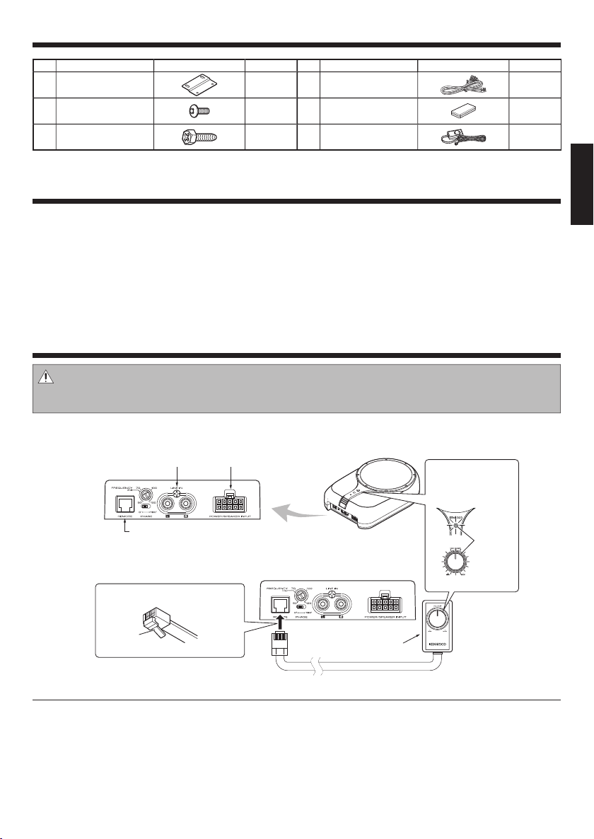
Connection
Caution:
Before wiring, be sure to remove the wire from the negative terminal of the battery. After completing all wiring, check the correct wirings again. After checking, connect the wire from the negative terminal of the battery.
7
Terminals of Subwoofer
LINE IN terminal
(for RCA pin jack)
POWER/SPEAKER INPUT terminal
(for Speaker cords)
When the power
turns ON, the
illumination lights.
ENGLISH
REMOTE terminal
7
Connecting the remote control unit
Connect with the lock part o f
remote control jack facing down.
Lock part
Notes:
• If the cord is not connected properly, the power indicator on the remote control unit and the illumination on the main unit
do not light up.
• If the remote control unit is not connected properly or at all, the subwoofer does not output the sound.
• Do not insert the remote control connector upside down or forcibly. Otherwise, malfunction may result.
Remote control
6
Lights in
blue.
English
3
 Loading...