

Kenwood KSC-256, KSC-356, KSC-326, KSC-316 Service Manual
MULTIPLE CHARGER
KSC-256/316/326/356
SERVICE MANUAL
© 2008-9 PRINTED IN JA PAN
B51-8844-00 (N) PDF
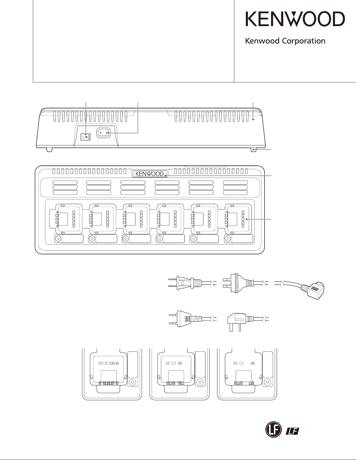
Power switch
(S66-0407-08)
Note:
The battery slots are molded for different model types.
The illustration shows the KSC-256.
The K type for KSC-356 and KSC-316 are not available.
The X type for KSC-316 is not available.
AC inlet
(E03-0462-08)
AC cord
(E30-7668-08): K
Cabinet
(A02-4058-08)
Foot
(J02-1303-08) x 4
Badge
(B43-1628-08)
Charging slot
(A02-4059-08): KSC-256
(A02-4060-08): KSC-326
(A02-4061-08): KSC-316
(A02-4062-08): KSC-356
AC cord
(E30-7669-08): X
AC cord
(E30-7670-08): E
Charging slot layout
ST
KSC-256/KSC-326 KSC-356 KSC-316
This product complies with the RoHS directive for the European market.
T
AC cord
(E30-7671-08): T
T
This product uses Lead Free solder.

KSC-256/316/326/356
DISASSEMBLY FOR REPAIR ...........................................3
TROUBLE SHOOTING .....................................................5
CHARGING FLOW CHART ............................................... 7
PARTS LIST ......................................................................8
EXPLODED VIEW ............................................................. 9
OPTIONAL ACCESSORY
KMB-30 (BRACKET) .................................................... 10
SPECIFICATIONS ........................................................... 11
CONTENTS
Document Copyrights
Copyright 2008 by Kenwood Corporation. All rights re-
served.
No part of this manual may be reproduced, translated,
distributed, or transmitted in any form or by any means,
electronic, mechanical, photocopying, recording, or otherwise, for any purpose without the prior written permission
of Kenwood.
Disclaimer
While every precaution has been taken in the preparation
of this manual, Kenwood assumes no responsibility for errors or omissions. Neither is any liability assumed for damages resulting from the use of the information contained
herein. Kenwood reserves the right to make changes to any
products herein at any time for improvement purposes.
2

KSC-256/316/326/356
DISASSEMBLY FOR REPAIR
Note:
Replacements are not possible other than for those items
listed in the bill of materials.
Other than the AC jack, the power switch, the fuse, and the
LED indicator, you cannot replace the parts on the printed
circuit board.
Alert: After the repairs have been completed, please perform a Megger insulation test on the ground side of the AC
jack and the charger terminal. The standard is 2MΩ or more.
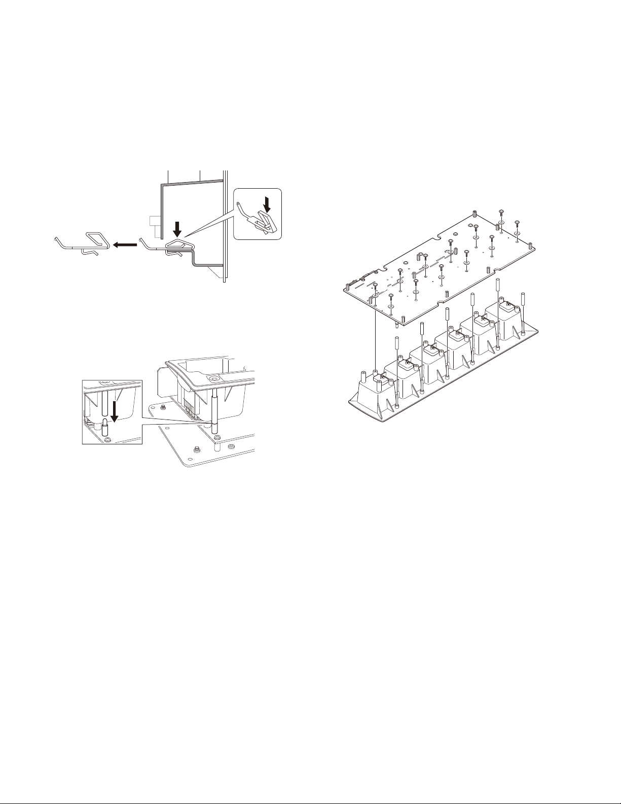
Removing the Upper Case
1. Remove the 10 screws ( q ) from the upper case.
2. Raise the case while pulling forward underneath where
the power switch hole is located ( w,e ).
(When pulling on the case without raising it, it will catch
where the power switch hole is located.)
Mounting position
of KMB-30
:
Mounting position
:
of KMB-30
:
:
:
Removing the Charging Slots
1. Remove the 11 screws ( q ) from the aluminum plate
and the 2 screws ( w ) from the charging slots to remove
the aluminum plate and insulating sheet.
2. Remove the 12 screws ( e ) holding the printed circuit
board to the charging slots to remove the charging slots.
Note: Refer to fi gure ( r ) during the removal in order to
retain the shading tubes of the LEDs.
Removing the Illumination Guide
1. Push the illumination guides through the charging slot
while the equipment is upside-down ( t ).
:
:
:
:
:
@
:
Insulating
sheet
:
:
.
.
.
;
@
=
3
KSC-256/316/326/356
DISASSEMBLY FOR REPAIR
Removing the Charging Terminal
1. While pushing down on the protruding charger terminal,
slide the terminal out.
Note: Clean the charger terminal landing by wiping it
with an alcohol dampened cloth.
Installing the Shading Tube
1. After installing the charging slots onto the printed circuit
board, verify that the shading tubes cover the heads of
the LEDs.
Installing the LEDs
1. Install the LEDs onto the printed circuit board in the manner shown in Exploded view.
Installing the Charging Slot
1. When installing the charging slot to the PCB, tighten the
screw in the direction indicated (right edge).
:
:
@
.
;
=
B
B
;
=
@
.
4
 Loading...