

Page 1
RAPID CHARGER
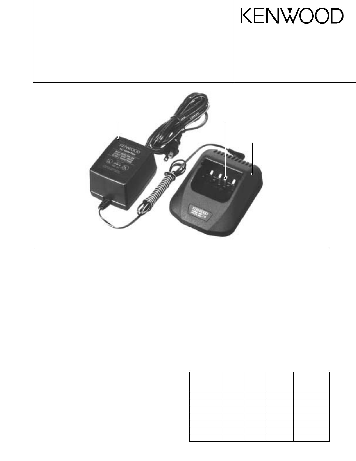
KSC-24
SERVICE MANUAL
AC adapter
(W08-0523-15) : K
(W08-0524-15) : E
(W08-0939-05) : T
© 2001-5 PRINTED IN JAPAN
B51-8583-00 (N) 1775
Relay terminal
(E23-1058-08) x 4
Cabinet (Upper)
(A02-3626-08)
Circuit Description
■ Power Supply Section
1. The power supply generates constant current (1.1A)
from the input voltage (rated 15V DC) from the adapter.
2. IC101 is a DC/DC converter.
3. R117 is a resistor for current detection.
4. R110 and R111 are resistors for no-load voltage detection (non-load voltage : 14V).
5. IC201 is a power supply/reset IC for the microcomputer
(IC202).
· Power output : 5V
· Reset output : “H” (Normal)
· After reset : “L”
■ Charging Control Section
1. The microcomputer (IC202) controls the following;
· Peak detection (Detected when fully charged, pin 27 of
IC202)
· Temperature control (Pin 2)
· Detection of abnormality, such as a short terminal (Pin
27)
· LED control (Red : Pin 21, Green : Pin 22)
· Trickle charging (Pin 18)
· Quick charging (Pin 17)
2. X201 is an oscillator that generates clocks for the microcomputer (4MHz).
Photo is K type.
■ Charging Switch Section
1. Q201 is a transistor that turns quick charging on and off.
2. Q202 is a transistor that turns trickle charging on and off.
3. The resistor (R204) determines the leakage current.
■ Display Section
1. LED201 is a two-color LED that indicates the charging
state.
2. Red on ............... Quick charging or warming up
Green on ............ Charging is complete
Red blinking ....... Abnormal (short terminal, short bat-
tery, or open terminal)
Charging
The charging time for each pack is shown in the table.
Battery Battery Voltage
Pack Type (Volts)
KNB-14 Ni-Cd 7.2 600 40
KNB-15A Ni-Cd 7.2 1100 60
KNB-16A Ni-Cd 7.2 1100 60
KNB-17A Ni-Cd 7.2 1500 80
KNB-20N Ni-MH 7.2 1600 80
KNB-21N Ni-MH 7.2 1600 80
KNB-22N Ni-MH 7.2 2100 110
Battery Approximate
Capacity Charging Time
(mAh) (Minutes)
Page 2

KSC-24
1
4x4
3
6
8
5
2
7x2
Ax2
A
A
701
PARTS LIST / EXPLODED VIEW / PC BOARD VIEW
Parts List
✽ : New parts
New
Ref. No.
1 ✽ A02-3626-08 Cabinet (Upper)
2 ✽ A02-3652-08 Cabinet (Lower)
3 E03-0187-08 DC jack
4 E23-1058-08 Relay terminal
5 F09-0455-08 Thermal fuse
6 F53-0149-08 Fuse (2A)
7 G13-1546-08 Cushion
A N80-2610-45 Pan head taptite screw
8 W02-1932-08 Electric circuit module
– W08-0523-15 AC adapter (120V/60Hz) K
– W08-0524-15 AC adapter (230V/50Hz) E
– ✽ W08-0939-05 AC adapter (230V/50Hz) T
Parts No. Description
parts nation
Exploded View
Desti-
PC Board View
2
Electric circuit module (W02-1932-08) Component side view
R202
R223
JP7
16
30
R221
1
4
IC202
D202
R210
Q104
Q103
D102
C111
R
G
LED201
R211
C102
R114
C104
+
FB101
L101
+
C110
R113
R112
Q101
GDS
2A
DZ101
117°C
TF101
JP1
R118
R119
R117
R115
R108
C105
R109
R116
R104
R107
Q102
JP4
R110
JP2
Q205
Q206
R105
R111
R101
C103
R106
16
IC101
R203
CE
9
Q202
B
C106
C107
C108
R204
18
Q201
JP5
R102
R103
JP3
R226
D201
Q204
R225
R201
C205
R209
R213
R215
R217
R212
Q203
JP6
R214
R216
8
IC201
5
15
1
R219
R218
C202
DZ202
R224
R222
C204
R220
R206
R205
R208
C203
DZ201
C101
C201
++
±
X201
T
JA1
+
125V 2.0A
F101
+
D101
+
Page 3

CIRCUIT DIAGRAM
KSC-24
: Not installed
*
Vcc : +5V
3
Page 4

KSC-24
Charging current ....................................... 1100 ± 150mA
Source voltage .......................................... Approx. 15V
Usable temperature range ........................ 0°C to 40°C (32°F to 104°F)
Line voltage (AC adapter) ......................... 120V AC (K)
Dimensions (Body only) ............................ 2-11/64 in (55mm) H x 4-1/8 in (105mm) W x 5-5/16 in (135mm) D
Weight (Body only) ................................... Approx. 180g / 6.3oz
SPECIFICATIONS
230V AC (E)
230V AC (T)
KENWOOD CORPORATION
14-6, Dogenzaka 1-chome, Shibuya-ku, Tokyo 150-8501, Japan
KENWOOD SERVICE CORPORATION
P.O. BOX 22745, 2201 East Dominguez Street, Long Beach, CA 90801-5745, U.S.A.
KENWOOD ELECTRONICS CANADA INC.
6070 Kestrel Road, Mississauga, Ontario, Canada L5T 1S8
KENWOOD ELECTRONICS DEUTSCHLAND GMBH
Rembrücker Str. 15, 63150 Heusenstamm, Germany
KENWOOD ELECTRONICS BELGIUM N.V.
Mechelsesteenweg 418 B-1930 Zaventem, Belgium
KENWOOD ELECTRONICS FRANCE S.A.
13, Boulevard Ney, 75018 Paris, France
KENWOOD ELECTRONICS U.K. LIMITED
KENWOOD House, Dwight Road, Watford, Herts., WD1 8EB United Kingdom
KENWOOD ELECTRONICS EUROPE B.V.
Amsterdamseweg 37, 1422 AC Uithoorn, The Netherlands
KENWOOD ELECTRONICS ITALIA S.p.A.
Via G. Sirtori, 7/9 20129 Milano, Italy
KENWOOD IBERICA S.A.
Bolivia, 239-08020 Barcelona, Spain
KENWOOD ELECTRONICS AUSTRALIA PTY. LTD.
(A.C.N. 001 499 074)
16 Giffnock Avenue, Centrecourt Estate, North Ryde, N.S.W. 2113 Australia
KENWOOD ELECTRONICS (HONG KONG) LTD.
Unit 3712-3724, Level 37, Tower one Metroplaza, 223 Hing Fong Road, Kwai Fong, N.T., Hong Kong
KENWOOD ELECTRONICS TECHNOLOGIES(S) PTE LTD.
Sales Marketing Division
1 Ang Mo Kio Street 63, Singapore 569110
 Loading...