

Page 1

AUDIO VIDEO SURROUND RECEIVER
VR-507
KRF-V7050D
INSTRUCTION MANUAL
KENWOOD CORPORATION
This instruction manual is used to describe multiple models listed above.
Model availability and features (functions) may differ depending on the country and
sales area.
About the supplied remote control
Compared to standard remote controls, the remote control supplied with this receiver has several operation
modes. These modes enable the remote control to control other audio/video components. In order to
effectively use the remote control it is important to read the operating instructions and obtain a proper
understanding of the remote control and how to switch its operation modes (etc.).
Using the remote control without completely understanding its design and how to switch the operation modes
may result in incorrect operations.
Preparation
Operations
B60-5027-00 01 MA (K, P, Y, M, X, I) 0009
Remote Control
Additional Information
Page 2
Before applying the power
Caution : Read this page carefully to ensure safe
operation.
Units are designed for operation as follows.
2
U.S.A. and Canada ........................................... AC 120 V only
Australia ........................................................... AC 240 V only
Europe and U.K. ............................................... AC 230 V only
China and Russia ............................................ AC 220 V only
Other countries ............ AC 110-120 / 220-240 V switchable*
Preparations
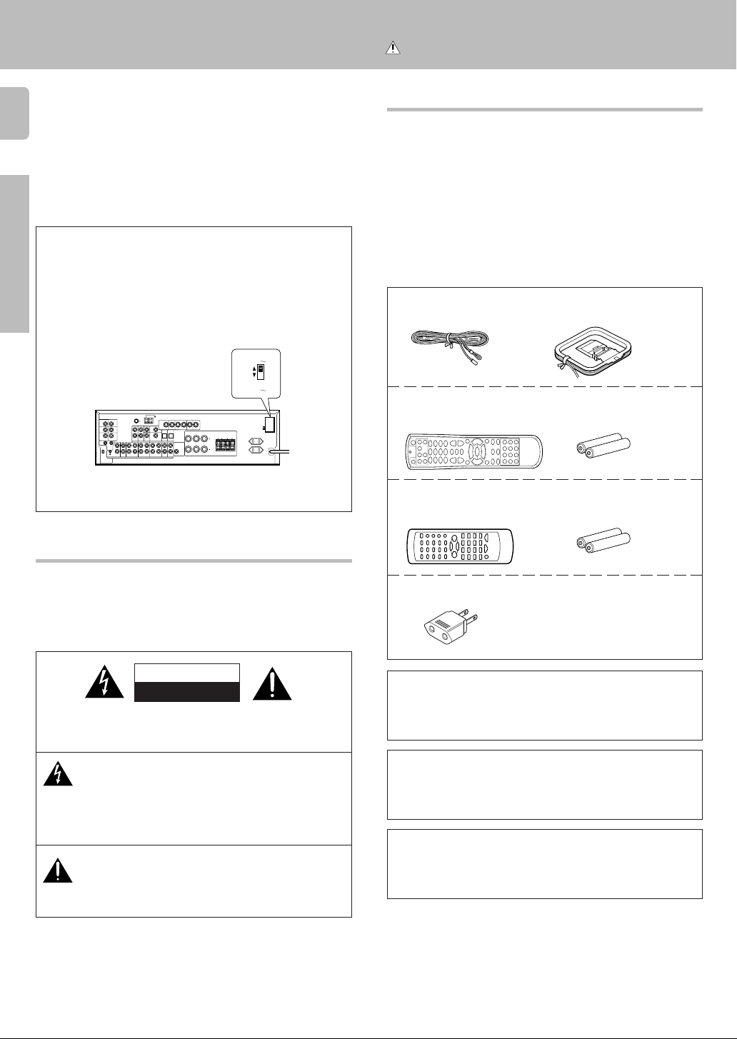
* AC voltage selection
The AC voltage selector switch on the rear panel is set to the voltage that
prevails in the area to which the unit is shipped. Before connecting the
power cord to your AC outlet, make sure that the setting position of this
switch matches your line voltage. If not, it must be set to your voltage
in accordance with the following direction.
AC voltage selector switch
Move switch lever to
match your line voltage
with a small screwdriver or other pointed
tool.
L
R
75µs
AM 10kHz
FM 100kHz
50µs
AM 9kHz
FM 50kHz
DEEMPHASIS
CHANNEL
SPACE
PLAY INPLAY INPLAY INREC OUTPLAY IN
MONITOR
OUT
DVD
VIDEO 3VIDEO 2VIDEO 1
VIDEO 1
RALC
Note:
Our warranty does not cover damage caused by excessive line voltage
due to improper setting of the AC voltage selector switch.
AC 220V 240V
AC 110V 120V
B
LR
LR
Unpacking
Unpack the unit carefully and make sure that all accessories are put aside
so they will not be lost.
Examine the unit for any possibility of shipping damage. If your unit is
damaged or fails to operate, notify your dealer immediately. If your unit
was shipped to you directly, notify the shipping company without delay.
Only the consignee (the person or company receiving the unit) can file a
claim against the carrier for shipping damage.
We recommend that you retain the original carton and packing materials
for use should you transport or ship the unit in the future.
Keep this manual handy for future reference.
Accessories
FM indoor antenna (1)
For VR-507
Remote control unit (1)
RC-R0720
For KRF-V7050D
Remote control unit (1)
RC-R0613
AM loop antenna (1)
Batteries (R6/AA) (2)
Batteries (R6/AA) (2)
Safety precautions
WARNING :
TO PREVENT FIRE OR ELECTRIC SHOCK, DO
NOT EXPOSE THIS APPLIANCE TO RAIN OR
MOISTURE.
CAUTION
RISK OF ELECTRIC SHOCK
DO NOT OPEN
CAUTION: TO REDUCE THE RISK OF ELECTRIC SHOCK, DO NOT
REMOVE COVER (OR BACK). NO USER-SERVICEABLE PARTS INSIDE, REFER SERVICING TO QUALIFIED SERVICE PERSONNEL.
THE LIGHTNING FLASH WITH ARROWHEAD SYMBOL,
WITHIN AN EQUILATERAL TRIANGLE, IS INTENDED TO ALERT
THE USER TO THE PRESENCE OF UNINSULATED “DANGEROUS VOLTAGE” WITHIN THE PRODUCT’S ENCLOSURE
THAT MAY BE OF SUFFICIENT MAGNITUDE TO CONSTITUTE A RISK OF ELECTRIC SHOCK TO PERSONS.
THE EXCLAMATION POINT WITHIN AN EQUILATERAL TRIANGLE IS INTENDED TO ALERT THE USER TO THE PRESENCE OF IMPORTANT OPERATING AND MAINTENANCE
(SERVICING) INSTRUCTIONS IN THE LITERATURE ACCOMPANYING THE APPLIANCE.
*AC plug adaptor (1)
*Use to adapt the plug on the power
cord to the shape of the wall outlet.
(Accessory only for regions where use
is necessary.)
Microcomputer malfunction
If operation is not possible or an erroneous display appears, even though
all connections have been made properly, reset the microcomputer
referring to “In case of difficulty”. t
Maintenance of the unit
When the front panel or case becomes dirty, wipe with a soft, dry
cloth. Do not use thinner, benzine, alcohol, etc. for these agents may
cause discoloration.
In regard to contact cleaner
Do not use contact cleaners because it could cause a malfunction.
Be specially careful not to use contact cleaners containing oil, for
they may deform the plastic component.
Page 3
Contents
Caution : Read the pages marked carefully to ensure safe operation.
Before applying the power
3
Preparations
Operations
Remote Control
Before applying the power ................... 2
Safety precautions .............................................. 2
Unpacking .......................................................... 2
How to use this manual ...................................... 4
Special features .................................................. 5
Names and functions of parts ................ 6
Remote control unit (RC-R0720) (VR-507).......... 7
Remote control unit (RC-R0613) (KRF-V7050D)
.. 8
Setting up the system ......................... 9
Connecting audio components ......................... 10
Connecting video components ......................... 11
Connecting a DVD player (6-channel input) ...... 12
Digital connections ........................................... 13
Connecting to the AV AUX jacks ...................... 14
Connecting the antennas .................................. 14
Connecting the system control ......................... 15
Connecting the speakers ..................................16
Connecting the terminals .................................. 17
Preparing the remote control ............................ 18
Preparing for surround sound ............... 19
Speaker settings ............................................... 19
Normal playback .............................. 20
Preparing for playback ...................................... 20
Listening to a source component ..................... 21
Adjusting the sound .......................................... 21
Recording ...................................... 22
Recording audio (analog sources) .................... 22
Recording video ................................................ 23
Recording audio (digital sources) ...................... 23
Listening to radio broadcasts ............... 23
Tuning radio stations ........................................ 23
Presetting radio stations manually .................... 24
Receiving preset stations .................................. 24
Receiving preset stations in order (P.CALL) ...... 24
Ambience effects .............................. 25
Surround modes ............................................... 25
Surround play ................................................... 27
DVD 6-channel playback .................................. 28
Convenient functions ........................................ 28
Basic remote control operations for other
components .................................... 31
Registering setup codes for other
components (RC-R0720) .................................. 31
Programming TV/VCR combo control .............. 31
Searching for your code ................................... 32
Checking the codes .......................................... 32
Re-assigning device keys ................................. 32
Changing volume lock ...................................... 33
Operating other components ............................ 33
Registering setup codes for other
components (RC-R0613) .................................. 34
Operating other components (RC-R0613) ........ 34
Setup code chart (for VR-507 (RC-R0720)) ...... 35
Setup code chart (for KRF-V7050D
(RC-R0613)) ...................................................... 39
CASSETTE deck, CD player & MD recorder
operations ......................................................... 40
Other components’ operations ......................... 42
Additional
Information
In case of difficulty ........................... 45
Specifications ................................. 47
For the U.S.A.
FCC WARNING
This equipment may generate or use radio frequency energy. Changes
or modifications to this equipment may cause harmful interference
unless the modifications are expressly approved in the instruction
manual. The user could lose the authority to operate this equipment if an
unauthorized change or modification is made.
NOTE:
This equipment has been tested and found to comply with the limits for
a Class B digital device, pursuant to Part 15 of the FCC Rules. These limits
are designed to provide reasonable protection against harmful interference in a residential installation. This equipment may cause harmful
interference to radio communications, if it is not installed and used in
accordance with the instructions. However, there is no guarantee that
interference will not occur in a particular installation. If this equipment does
cause harmful interference to radio or television reception, which can be
determined by turning the equipment off and on, the user is encouraged
to try to correct the interference by one or more of the following measures:
– – Reorient or relocate the receiving antenna.
– – Increase the separation between the equipment and receiver.
– – Connect the equipment into an outlet on a circuit different from that
to which the receiver is connected.
– – Consult the dealer or an experienced radio / TV technician for help.
For the U.S.A.
Note to CATV system installer:
This reminder is provided to call the CATV system installer's attention to
Article 820-40 of the NEC that provides guidelines for proper grounding
and, in particular, specifies that the cable ground shall be connected to
the grounding system of the building, as close to the point of cable entry
as practical.
As an ENERGY STAR® Partner, Kenwood Corporation has determined that this product meets the
ENERGY STAR
This product can save energy. Saving energy reduces air pollution and
lowers utility bills.
®
guidelines for energy efficiency.
Preparations
Operations
Remote Control
Additional Information
Page 4

How to use this manual
4
This manual covers the VR-507 and KRF-V7050D. Items such as functions,
number of jacks, and remote control details somewhat differ between
these models. To confirm the functions available on the model you have
purchased, refer to the table below.
Model name
Preparations
VR-507 RC-R0720 2 systems Equipped Equipped
KRF-V7050D RC-R0613 2 systems Equipped Equipped
This manual is divided into four sections, Preparations, Operations,
Remote Control, and Additional Information.
Remote
Control
Speaker out Video 3 Front input
(A, B)
(A, B)
Preparations
Shows you how to connect your audio and video components to the
receiver and prepare the surround processor.
We will guide you to make setting up your system as easy as possible.
However, since this receiver works with all of your audio and video
components, connecting the system can be fairly complex.
Operations
Shows you how to operate the various functions available on the receiver.
Remote Control
Shows you how to operate other components using the remote control,
as well as a detailed explanation of all remote control operations. Once
you have registered your components with the proper setup codes, you’ll
be able to operate both this receiver and your other AV components (TV,
VCR, DVD player, CD player, etc.) using the remote control supplied with
this receiver.
Additional Information
Shows you additional information such as “In case of difficulty”
(troubleshooting) and “Specifications”.
Terminal
jacks
Before applying the power
Memory back up function
Please note that the following items will be deleted from the unit's
memory if the power cord is disconnected from the AC outlet for
approximately 2 days.
• Power mode.
• Input selector settings.
• Device preset.
• Picture output.
• Speaker ON/OFF
• Volume level.
• BASS, TREBLE, INPUT level.
• Subwoofer ON/OFF.
• Dimmer level.
• Monitor ON/OFF.
• MD/TAPE settings.
• 6ch/2ch input setting.
• Listen mode setting.
• Speaker settings.
• Input mode setting.
• Midnight mode setting.
• Broadcast band.
• Frequency setting.
• Preset stations.
• Tuning mode.
• CINEMA EQ.
• Source Direct.
Page 5
Special features
True home theater sound
This receiver incorporates a wide variety of surround modes to bring you
maximum enjoyment from your video software. Select a surround mode
according to your equipment or the software you are going to play and
enjoy! ∞
Dolby Digital
The DOLBY DIGITAL mode lets you enjoy full digital surround from
software processed in the Dolby Digital format. Dolby Digital provides
up to 5.1 channels of independent digital audio for better sound quality
and more powerful presence than conventional Dolby Surround.
Dolby PRO LOGIC II
Pro Logic II, whilst totally compatible with its predecessor PRO LOGIC,
provides greater advantages in surround sound. It allows user to enjoy
the conventional stereo or Dolby Surround with a convincing “5.1 like”
presentation. PRO LOGIC II offers special features for controlling the
overall spatial, dimensionality and frontal sound field imaging. Dolby
PRO LOGIC II produces an impressive surround sound from video
software marked
music CD. When listening to music, you will be able to enjoy the
experience of sheer STEREO surround sound.
Dolby 3 Stereo
This surround system reproduces theater-like surround sound from
video software marked
The 3 STEREO mode will redirect the Surround signal to the front left
and right speakers when only the front and center speakers are used.
DTS
DTS (Digital Theater System) is a 5.1 channel digital audio format that
provides five full-spectrum channels and one low-frequency (subwoofer)
channel for unprecedented clarity, optimum channel separation and a
(wide) dynamic range.
In the DTS mode, the 5.1 channel digital input from a DTS CD, LD or
DVD disc (carrying the “DTS” marking) can be played in Digital Surround.
Important:
When a DTS disc is played on a CD, LD or DVD player, noise may be
output from the analog output. It is recommended that you connect the
digital output of the player to the digital input of this unit.
and three-dimensional space from
.
Before applying the power
Multi channel music (SRS Circle Surround )
SRS Circle surround enables you to listen to multi channel sound from the
stereo source. We assume you have already enjoyed listening to Dolby
digital sound/DTS multi channel sound with your multi speakers. Now,
this time try listening to the stereo source (ex. Audio CD) using your multi
speakers. You may discover a new type of “stereo” sound through SRS
Circle Surround.
DSP surround modes
The DSP (Digital Signal Processor) used for this receiver incorporates a
variety of high quality adjustable sound fields, like “ARENA”, “JAZZ
CLUB”, THEATER”, STADIUM” and “DISCO”. It is compatible with
almost any kind of program source.
DVD 6-channel input
If you own a DVD player equipped with 6-channel output, this receiver
allows you to obtain the full surround sound impact of DVD source
material featuring multi-channel encoding. Since the source signals are
digital and each channel is input independently, the resulting ambience
is far superior to what can be achieved with conventional surround sound
systems.
CINEMA EQ.
Cinema EQ. mode will produce a more dynamic sound quality in any
conditions. You can enjoy a more impressive sound effect when you
switch CINEMA EQ. ON during Dolby Digital and DTS playback.
Universal IR (InfraRed) remote control
In addition to the basic receiver, the remote control supplied with this
receiver can also operate almost all of your remote controllable audio and
video components. Just follow the simple setup procedure to register the
components you have connected.
5
Preparation
Page 6
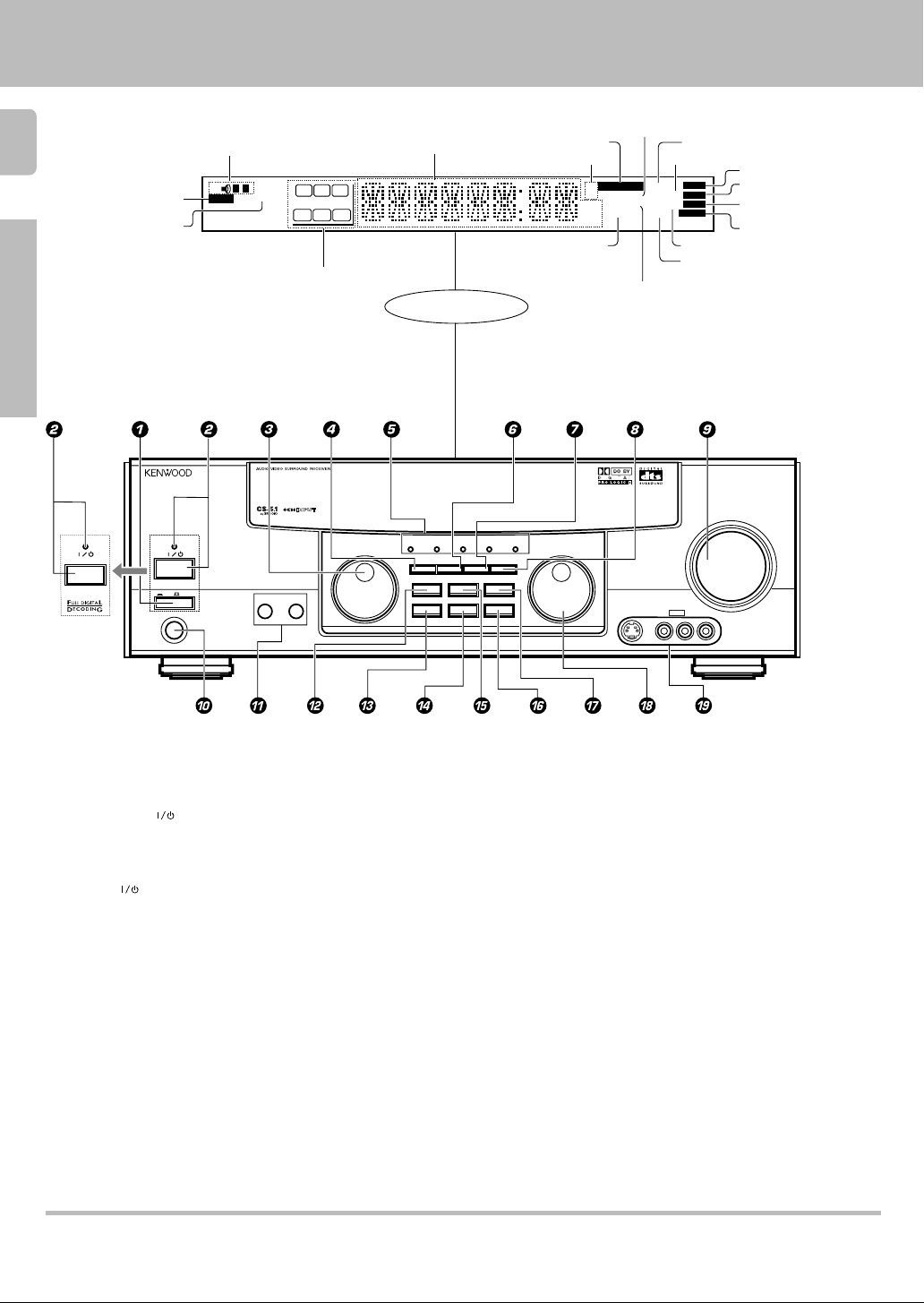
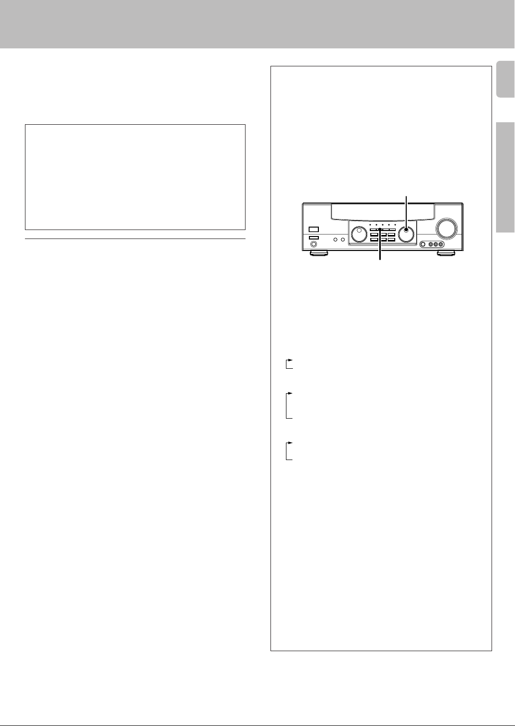
Names and functions of parts
6
Preparations
STANDBY
POWER
ON/STANDBY
For VR-507
Speaker indicator
CLIP indicator
MUTE indicator
STANDBY
ON/STANDBY
POWER
ON OFF
PHONES
TI.VOL
SP
AB
CLIP
MUTE
RDS EON PTY
TP
TA NEWS
Speaker selection indicators
Input channel indicators
Output channel indicators
A SPEAKERS B
C
LFE SW
S SRSL
Frequency display,
Input display,
Preset channel display,
Surround mode display
RL
Display
DOLBY
DTS
MULTI CONTROL
DIGITAL
INPUT MODESET UP
SOUND
BAND MEMORY
AUTO SOUND indicator
Band indicators
DOWNMIX indicator
PRO LOGIC 3 STEREO CS 5.1
DIMMER MONITOR
LISTEN MODE
SOURCE DIRECT
AUTO/CINEMA EQ.
INPUT SELECTOR
MHz
kHz
FM
AM
PRO LOGIC
indicator
S.DIRECT indicator
AUTO
DIGITAL
AUTO SOUND
PRO LOGIC
3 STEREO
DOWNMIX
3 STEREO indicator
STEREO indicator
S-VIDEO V L – AUDIO – R
S.DIRECT
MONITOR
DSP
MEMO
TUNED
AV AUX
DIGITAL indicator
AUTO indicator
MEMO indicator
ST.
ST. indicator
TUNED indicator
MONITOR indicator
DSP indicator
VOLUME CONTROL
UPDOWN
1 POWER key (For KRF-V7050D) (
Use to turn the main power ON/OFF.
2 ON/STANDBY (
) key (
(For KRF-V7050D)
Use to switch the power ON/STANDBY when
the POWER is turned ON.
STANDBY indicator
2 POWER (
) key (For VR-507) (
Use to turn the power ON/STANDBY.
STANDBY indicator
3 MULTI CONTROL knob (
Use to control a variety of settings.
4 SET UP key (
Use to select the speakers' settings etc.
5 Surround indicators
DTS indicator ¶
Lights when the receiver is in the DTS mode.
DOLBY DIGITAL indicator ¶
Lights when the receiver is in the Dolby Digital
mode.
PRO LOGIC indicator ¶
Lights when the receiver is in the PRO LOGIC
3 STEREO indicator ¶
Lights when the receiver is in the 3 STEREO
mode.
CS 5.1 indicator ¶
Lights when the receiver is in the CS 5.1 mode.
6 INPUT MODE key 9
Use to switch between the digital and analog
inputs.
7 DIMMER key £º
Use to adjust the brightness of the display.
Use to select the REC MODE.
8 MONITOR key ™
Use to monitor the source that is connected to
the MONITOR jack.
9 VOLUME CONTROL knob ¡
0 PHONES jack ™
Use for headphone listening.
! SPEAKERS A/B keys )
Use to turn the A/B speakers ON/OFF.
@ SOUND key •
Use to adjust the sound quality and the ambience effects.
# BAND key £
Use to select the broadcast band.
$ AUTO/CINEMA EQ. key
Use to change “TAPE” indication to “MD”.
)
Use to select the auto tuning mode. £
Use to switch the status of CINEMA EQ.
™
% LISTEN MODE key ¶
Use to select the listening mode.
^ MEMORY key ™
Use to store radio stations in the preset memory.
& SOURCE DIRECT key ¢
Use to pass the source material directly to the
amplifier.
* INPUT SELECTOR knob ¡
Use to select the input sources.
( AV AUX (S VIDEO, V, AUDIO L/R) jacks
$
mode.
Standby mode
When standby indicator is lit, this receiver is in standby mode and consumes a small amount of curent for back-up. This system can be switched on using
remote controls.
Page 7
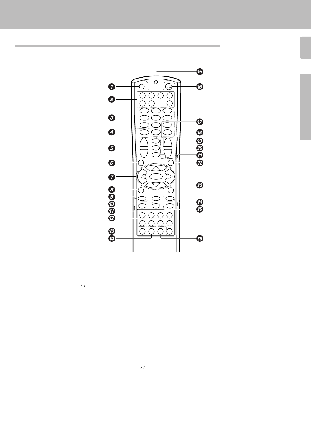
Remote control unit (RC-R0720) (VR-507)
This remote control unit can be used not only for Kenwood products but also for other non-Kenwood products by
setting the appropriate maker setup codes. ⁄
Names and functions of parts
7
SET UP
DVD CBL VCR TV
DSS
123
456
789
MUTE
+
VOLUME
GUIDE
SETUP
P.CALL
REC M.
INFO/OSD
16¡
REC
¶78
DISC SEL.
POWER
RECEIVER
CD
0
+10
ENTER
¢
LSTN.M
+
LAST
SOUND
DVD
CHANNEL
SLEEP
CINE.EQ
4
INPUT
EXIT/RETURN
MULTI CONTROL
SELECT
MULTI CONTROL
BAND
A/B +100
AUTO
TUNERPHONO MD/TAPE CD/DVD
VIDEO2VIDEO1 VIDEO3 DVD
DISC SKIP
BASS BOOST
AV AUX
DIM.
MENU
P.CALL
Preparation
¢4
If the name of a function is different on
the receiver and on the remote control,
the name of the remote control key in
this manual is indicated in parentheses.
1 SET UP key ⁄
Use to register other components.
2 Source key (DVD, CBL, VCR, TV, DSS,
CD, RECEIVER)
Use to select the components registered at the
respective input. Press POWER (
switch the component ON/OFF.
3 Numeric keys ⁄
Provide functions identical to those of the
original remote control supplied with the
component you are controlling.
4 MUTE key ™
Use to temporarily mute the sound.
5 VOLUME +/– keys ¡
Use to adjust the receiver volume.
6 GUIDE key
Use to operate other components.
SET UP key (
Use to select the speakers’ settings etc.
7 MULTI CONTROL keys (
Use to control a variety of settings.
Use to operate other components.
P.CALL 4/¢ keys ¢
If tuner is selected as the input source, these
keys function as P.CALL keys.
SELECT key
Use to operate other components.
8 REC M. key
Use to select the REC MODE.
INFO/OSD key
Use to operate other components.
9 TUNING 1/¡ key
Use to operate the tuner or selected
component.
If CD, MD or TAPE is selected as the input
source, this key functions as search key.
) key to
0 BAND key £
Use to select the broadcast band.
6 key
If CD is selected as the input source, this key
functions as the play/pause key.
If MD or TAPE is selected as the input
source, this key functions as the play key.
! ¶ key
If VCR is selected, this key functions as
record key.
If TAPE is selected, this key functions as
reverse play key.
@ INPUT SELECTOR keys (PHONO,
TUNER, MD/TAPE, CD/DVD, VIDEO1,
VIDEO2, VIDEO3, DVD, AV AUX) ¡
Use to select the input sources.
# DISC SEL. key
Use to operate other components.
$ DISC SKIP key
If CD is selected as the input source, this key
functions as the multi-CD player disc skip key.
% LED indicator
Blinks to show that a signal is sending.
^ POWER (
Use to switch the receiver and other
registered components ON/OFF.
& LSTN.M key ¶
Use to select the listening mode.
LAST key
Use to operate other components.
* ENTER key
Use to operate other components.
( SOUND key •
Use to adjust the sound quality and the
ambience effects.
) key *⁄
SLEEP key
Use to operate other components.
) CHANNEL +/– keys
Use to select the channel.
4 DVD ¢ keys
When in DVD player operations, these keys
function as skip keys.
¡ CINE.EQ key ™
Use to switch the status of CINEMA EQ.
INPUT key
Use to operate other components.
™ EXIT/RETURN key
Use to operate other components.
£ DIM. key
Use to adjust the brightness of the display.
MENU key
Use to operate other components.
¢ A/B key
If TAPE is selected as the input source, this
is (A and B) of a double cassette deck.
+100 key
Use to select the disc number with the multiCD player.
8 key
Use to operate other components.
∞ AUTO key £
Use to select the auto tuning mode.
7 key
If CD, MD or TAPE is selected as the input
source, this key functions as the stop key.
§ BASS BOOST key ¡
Use to select the maximum adjustment
setting for the low frequency range.
Page 8
#
$
™
*
)
^
&
(
%
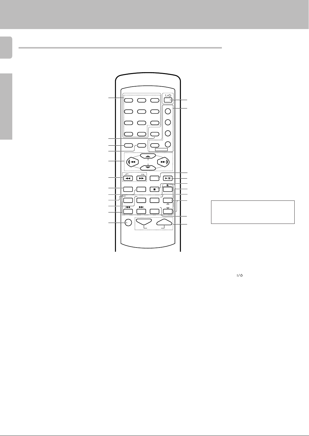
Remote control unit (RC-R0613) (KRF-V7050D)
8
This remote control unit can be used not only for Kenwood products but also for other non-Kenwood products by
setting the appropriate maker setup codes. ⁄
Names and functions of parts
Preparations
1
2
3
4
5
6
7
8
9
0
!
@
POWER
1
23
RETURN
LSTN M.
DSS
POWER
ENTER
CINE.EQ
AUTO
INPUT SEL.TITLE
TUNER
DISC SEL.
TV
VCR
DVD
CABLE
P.CALL
BAND
DVD
MD/TAPE
CHANNEL
456
789
0 +10
OSDMENU
SET UP SOUND
P.CALL
MULTI CONTROL
TUNING
A/B+100
B.BOOST
DISC SKIP
RECEIVER
TV SEL.
PHONO CD/DVD
DVD
VIDEO1 VIDEO2 VIDEO3 AV AUX
MUTE VOLUME
¡
If the name of a function is different on
the receiver and on the remote control,
the name of the remote control key in
this manual is indicated in parentheses.
1 Numeric keys ⁄
Provide functions identical to those of the
original remote control supplied with the
component you are controlling.
2 LSTN M. key ¶
Use to select the listening mode.
RETURN key
Use to operate other components.
3 SET UP key (
Use to select the speakers' settings etc.
MENU key
Use to operate other components.
4 SOUND key •
Use to adjust the sound quality and
ambience effects.
OSD key
Use to operate other components.
5 MULTI CONTROL keys (
Use to control a variety of settings.
Use to operate other components.
P.CALL 4/¢ keys ¢
If tuner is selected as the input source,
these keys function as P.CALL keys.
4/¢ keys
If CD or MD is selected as the input
source, these keys function as skip keys.
6 TUNING 1/¡ keys
Use to operate the tuner or selected
component.
If CD, MD or TAPE is selected as the input
source, these keys function as search
keys.
7 B.BOOST key ¡
Use to select the maximum adjustment
setting for the low frequency range.
RECEIVER key
Use to return to the operation of the
receiver.
8 DISC SKIP key
If CD is selected as the input source, this
key functions as the multi-CD player disc
skip key.
A/B key
If TAPE is selected as the input source,
this is (A and B) of a double cassette
deck.
+100 key
Use to select the disc number with the
multi-CD player.
9 TITLE key
Use to operate other components.
0 TV SEL. key
Use to operate other components.
! INPUT SELECTOR keys (DVD,
PHONO, CD/DVD, TUNER, MD/TAPE,
VIDEO1, VIDEO2, VIDEO3, AV AUX)
Use to select the input sources.
4 DVD ¢ keys
When in DVD player operations, these
keys function as skip keys.
@ MUTE key ™
Use to temporarily mute the sound.
¡
# POWER (
Use to turn the receiver on and off.
$ Source POWER key (TV, VCR, DVD,
DSS, CABLE)
Use to turn the other components on and off.
% ENTER key
Use to operate other components.
CINE.EQ key ™
Use to switch the status of CINEMA EQ.
^ BAND key £
Use to select the broadcast band.
6 key
If CD is selected as the input source, this
key functions as the play/pause key.
If MD or TAPE is selected as the input
source, this key functions as the play key.
& AUTO key £
Use to select the auto tuning mode.
7 key
If CD, MD or TAPE is selected as the input
source, this key functions as the stop key.
* 8 key
Use to operate other components.
( INPUT SEL. key
Use to operate other components.
) CHANNEL %¥fi key
Use to select the channel.
¡ DISC SEL. key
Use to operate other components.
™ VOLUME keys ¡
Use to adjust the receiver volume.
) key (
Page 9
Setting up the system
Make connections as shown in the following pages.
When connecting the related system components, be sure
to also refer to the instruction manuals supplied with the
components you are connecting.
Do not connect the power cord to a wall outlet until all
connections are completed.
DTS disclaimer clause
DTS Digital Surround™ is a discrete 5.1 channel digital audio format
available on CD, LD, and DVD software which consequently cannot be
decoded and played back inside most CD, LD, or DVD players. For this
reason, when DTS-encoded software is played back through the analog
outputs of the CD, LD, or DVD player, excessive noise will be exhibited.
To avoid possible damage to the audio system, proper precautions
should be taken by the consumer if the analog outputs are connected
directly to an amplification system. To enjoy DTS Digital Surround™
playback, an external 5.1 channel DTS Digital Surround™ decoder
system must be connected to the digital output (S/P DIF, AES/EBU, or
TosLink) of the CD, LD or DVD player.
Notes
1. Be sure to insert all connection cords securely. If their connections are
imperfect, the sound may not be produced or noise may interfere.
2. Be sure to remove the power cord from the AC outlet before plugging or
unplugging any connection cords. Plugging/unplugging connection cords
without disconnecting the power cord can cause malfunctions and may
damage the unit.
3. Do not connect power cords from components whose power consumption is larger than what is indicated on the AC outlet at the rear of this unit.
Analog connections
Audio connections are made using RCA pin cords. These cables transfer
stereo audio signal in an “analog” form. This means the audio signal
corresponds to the actual audio of two channels. These cables usually have
2 plugs each end, one red for the right channel and one white for the left
channel. These cables are usually packed together with the source unit, or
are available at your local electronics retailer.
Input mode settings
CD/DVD, VIDEO2, VIDEO3 and DVD/6ch inputs each include jacks
for digital audio input and analog audio input.
You must select beforehand which type of input is to be used for each
connected component.
The initial factory settings for audio signal playback (CD/DVD,
DVD/6ch) and (VIDEO2, VIDEO3) are digital and analog respectively.
To use the analog audio input for playback instead (if, for example, you
have connected a VCR to the VIDEO2 or VIDEO3 input), you must set
the input mode for the corresponding input to the analog mode.
After completing connections and turning on the receiver, follow the
steps below.
INPUT SELECTOR
INPUT MODE
1 Use the INPUT SELECTOR knob to select CD/DVD, VIDEO2,
VIDEO3 or DVD/6ch.
2 Press the INPUT MODE key.
Each press switches the setting as follows:
In DTS play mode
1 D-AUTO (digital input, auto sound)
2 D-MANUAL (digital input, manual sound)
In DVD/6ch play mode
1 D-AUTO (digital input, auto sound)
2 D-MANUAL (digital input, manual sound)
3 6ch INPT (DVD/6ch input)
4 ANALOG (analog input, manual sound)
In modes other than DTS or DVD/6ch play mode
1 D-AUTO (digital input, auto sound)
2 D-MANUAL (digital input, manual sound)
3 ANALOG (analog input, manual sound)
9
Preparation
Digital input:
Select this setting to play digital signals from a DVD, CD, or LD player.
Analog input:
Select this setting to play analog signals from a cassette deck, VCR,
or record player.
Auto sound:
In the auto sound mode (AUTO SOUND indicator lights), the receiver
selects the listening mode automatically during playback to match the
type of input signal (Dolby Digital, PCM, DTS ) and the speaker setting.
The initial factory setting is auto sound on.
To keep the receiver set to the currently selected listening mode, use
the INPUT MODE key to select “D-MANUAL” (manual sound).
However, even when this setting is selected, there may be cases in
which the listening mode is selected automatically to match a Dolby
Digital source signal depending on the combination of listening mode
and source signal.
If the INPUT MODE key is pressed quickly, sound may not be
produced.
Page 10
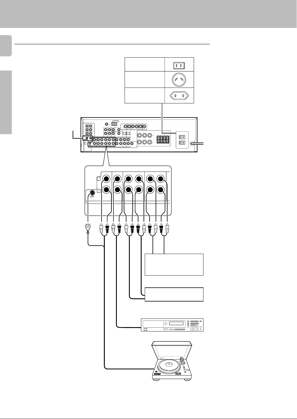
Connecting audio components
10
Setting up the system
Shape of AC outlets
U.S.A. and Canada
Australia
Preparations
SYSTEM CONTROL
jacks %
Other countries
L
75µs
AM 10kHz
FM 100kHz
50µs
AM 9kHz
FM 50kHz
R
DEEMPHASIS
CHANNEL
SPACE
L
R
GND
PHONO
CD/DVD
MONITOR
OUT
REC OUT
DVD
VIDEO 1
MD/TAPE
PLAY INPLAY INPLAY INREC OUTPLAY IN
VIDEO 3VIDEO 2VIDEO 1
RALC
REC OUT
IN
MONITOR
AUDIO
B
LR
LR
PLAY INPLAY IN
To AC wall outlet
OUT
Video component,
3 head cassette deck, or
Graphic equalizer ™
OUT
Cassette deck or
MD recorder
IN
OUT
CD or DVD player
OUT
Moving coil (MC) cartridge
record player cannot be used
directly from the receiver unit. It
can only be used when another
equalizer amplifier is connected.
Record player
Page 11
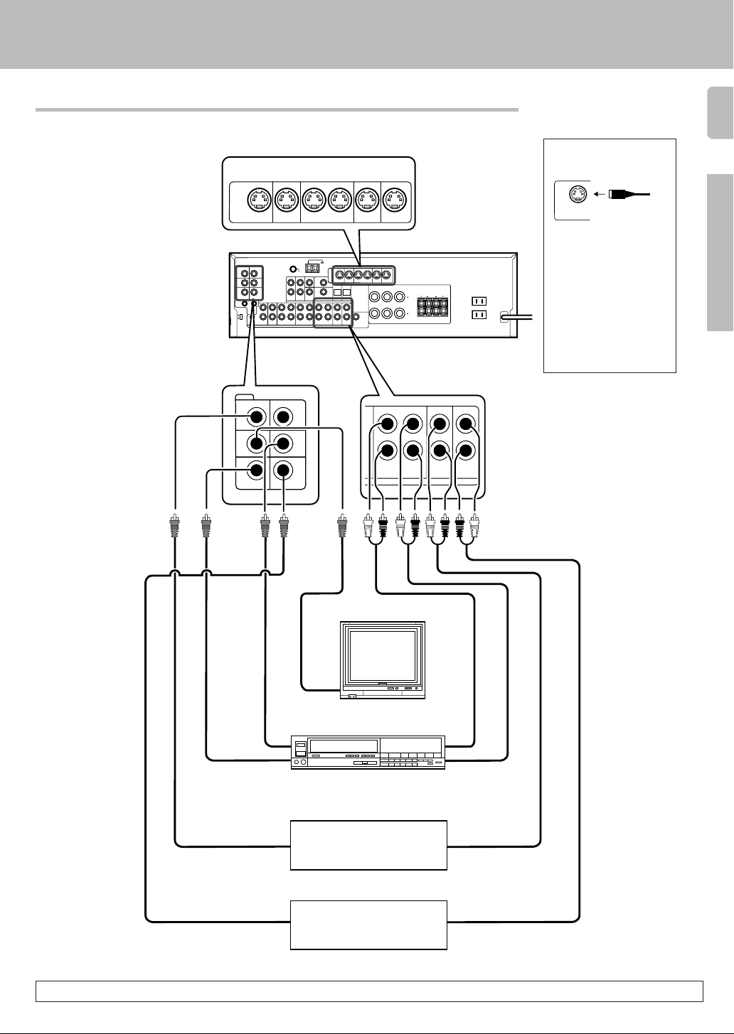
Connecting video components
S Video jacks
S VIDEO
75µs
AM 10kHz
FM 100kHz
50µs
AM 9kHz
FM 50kHz
VIDEO
PLAY IN REC OUT PLAY IN PLAY IN PLAY IN
MONITOR
DVD VIDEO 1 VIDEO 1 VIDEO 2 VIDEO 3
OUT
L
R
DEEMPHASIS
CHANNEL
SPACE
VIDEO 2 IN
CD/DVD
DVD
IN
Setting up the system
11
About the S VIDEO
jacks
S VIDEO
Use the S VIDEO jacks to
make connections to
video components with S
VIDEO IN/OUT jacks.
÷ If you use the S VIDEO
jacks to connect your video
playback components, be
sure to use the S VIDEO
jacks when connecting
your monitor and video
recording components.
Preparations
DVD
VIDEO 1
PLAY INPLAY INPLAY INREC OUTPLAY IN
VIDEO 3VIDEO 2VIDEO 1
RALC
B
LR
LR
MONITOR
OUT
Video
IN/OUT
MONITOR
OUT
VIDEO 1
OUT
VIDEO 3 INVIDEO 1 IN
Video deck
IN
OUT
Video inputs and
outputs
(Yellow RCA pin cords)
OUT
VIDEO 1 VIDEO 2 VIDEO 3
Monitor TV
VIDEO
IN
IN
Video inputs
(Yellow RCA pin cords)
DVD player or LD player
PLAY IN
PLAY IN PLAY INREC OUT
OUT
Audio inputs
and outputs
IN
OUT
Audio
IN/OUT
OUT
DVD player or LD player
OUT
A video component with digital audio outputs should be connected to the VIDEO2 or VIDEO3 jacks.
Page 12
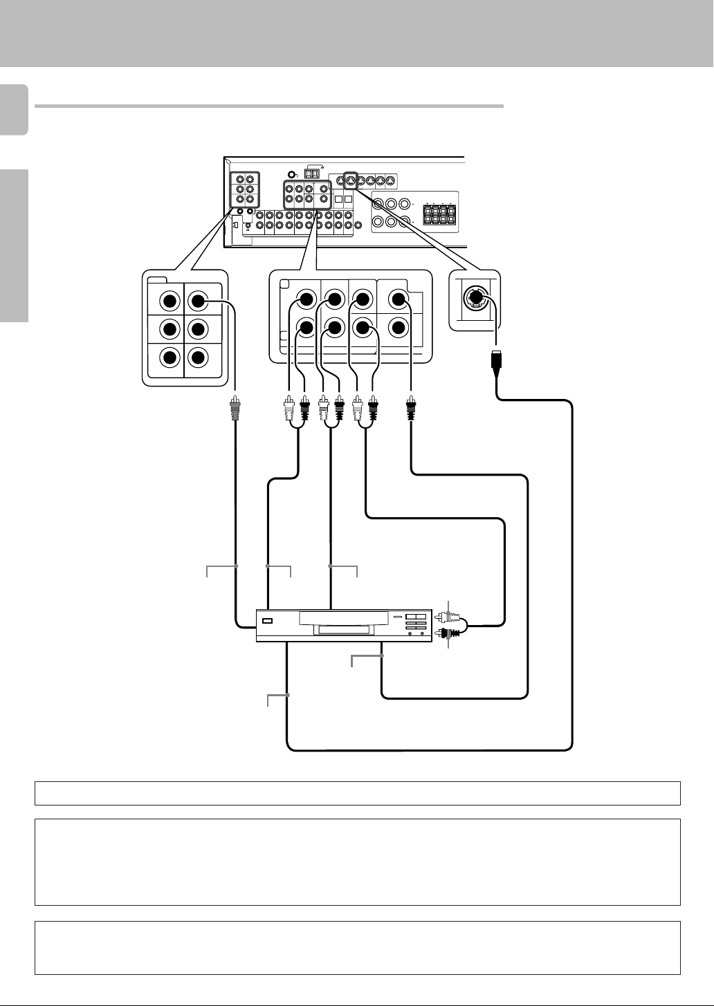
Connecting a DVD player (6-channel input)
12
If you have connected a DVD player to the receiver with digital connection, be sure to read the “Input mode settings”
section carefully. 9
Setting up the system
Preparations
VIDEO
VIDEO 2 IN
MONITOR
OUT
L
75µs
AM 10kHz
FM 100kHz
50µs
AM 9kHz
FM 50kHz
DEEMPHASIS
CHANNEL
SPACE
CD/DVD
IN
DVD
VIDEO 1
OUT
VIDEO 3 INVIDEO 1 IN
R
L
R
FRONT
DVD/6CH. INPUT
MONITOR
SURROUND
OUT
DVD
VIDEO 1
CENTER DVD
SUB
WOOFER
PLAY INPLAY INPLAY INREC OUTPLAY IN
VIDEO 3VIDEO 2VIDEO 1
RALC
VIDEO 2
COAXIAL
B
LR
LR
PLAY IN
DVD
S VIDEO cord
VIDEO OUT
(Yellow RCA
pin cord)
FRONT
OUT L/R
SURROUND
OUT L/R
CENTER OUT
DVD player
SUBWOOFER OUT
COAXIAL
DIGITAL
OUT
S VIDEO
OUT
(AUDIO)
To switch the speakers off, press the MUTE key.
CAUTION (Except for U.S.A. and Canada)
Be sure to adhere to the following. Or proper ventilation will be blocked causing damage or fire hazard.
• Do not place any object impairing heat radiation onto the top of the unit.
• Leave a space around the unit (from the largest outside dimension including projection) equal or greater than, shown below.
Top panel : 50 cm Side panel : 10 cm Back panel : 10 cm
CAUTION (For U.S.A. and Canada)
Be sure to adhere to the following. Or proper ventilation will be blocked causing damage or fire hazard.
• Do not place any object impairing heat radiation onto the top of the unit.
Page 13
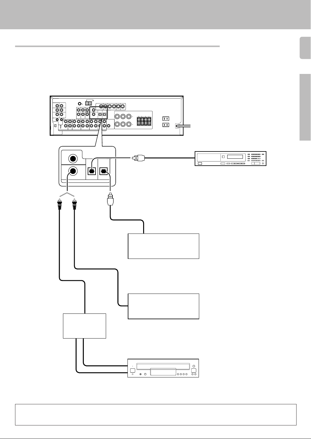
Digital connections
The digital in jacks can accept DTS, Dolby Digital, or PCM signals. Connect components capable of outputting DTS,
Dolby Digital, or standard PCM (CD) format digital signals.
If you have connected any digital components to the receiver, be sure to read the “Input mode settings” section
carefully. 9
Setting up the system
13
75µs
AM 10kHz
FM 100kHz
50µs
AM 9kHz
FM 50kHz
DEEMPHASIS
CHANNEL
SPACE
COAXIAL
DIGITAL
OUT
(AUDIO)
(sold separately)
L
R
DVD
VIDEO 2
COAXIAL
CD/DVD
OPTICAL
DIGITAL IN
RF digital
demodulator
(DEM-9991D)
MONITOR
OUT
VIDEO 3
OPTICAL
DVD
VIDEO 1
PLAY INPLAY INPLAY INREC OUTPLAY IN
VIDEO 3VIDEO 2VIDEO 1
RALC
B
LR
LR
Optical fiber cable
Optical fiber
cable
OPTICAL DIGITAL OUT
(AUDIO)
Component with DTS,
Dolby Digital, or PCM
OPTICAL DIGITAL OUT
Connect the video signal and digital
audio signals to the VIDEO 3 jacks.
(See “Connecting video components”.)
COAXIAL DIGITAL OUT
(AUDIO)
Component with DTS,
Dolby Digital, or PCM
COAXIAL DIGITAL OUT
Connect the video signal and analog
audio signals to the VIDEO 2 jacks.
(See “Connecting video components”.)
Preparations
OPTICAL DIGITAL OUT (AUDIO)
CD or DVD player
!
!
DOLBY DIGITAL RF
OUT (AUDIO)
PCM OUT
LD player
To connect an LD player with a DIGITAL RF OUT, connect the LD player to the KENWOOD RF digital demodulator (DEM-9991D).
Next, connect the DIGITAL OUT jacks of the demodulator to the DIGITAL IN jacks of the receiver.
Connect the video signal and analog audio signals to the VIDEO 2 or VIDEO 3 jacks. (See “Connecting video components”.)
Page 14
Setting up the system
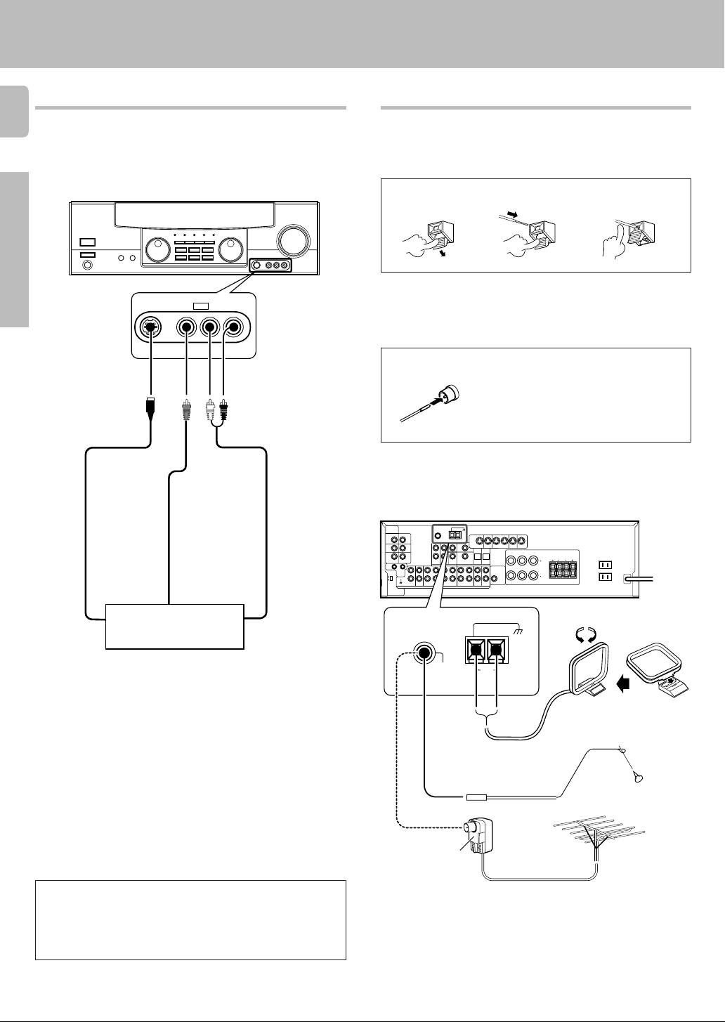
Connecting to the AV AUX jacks
14
The AV AUX jacks are convenient for connection of video components
such as a camcorder or a video game.
Preparations
S VIDEO V L — AUDIO — R
S VIDEO cord
AV AUX
Connecting the antennas
AM loop antenna
The supplied loop antenna is for use indoors. Place it as far as possible from
the receiver, TV set, speaker cords and power cord, and adjust the direction
for best reception.
AM antenna terminal connections
1 Push lever. 2 Insert cord.
FM indoor antenna
The supplied indoor antenna is for temporary use only. For stable signal
reception we recommend using an outdoor antenna. Disconnect the indoor
antenna when you connect one outdoors.
FM antenna terminal connections
Insert cord.
FM outdoor antenna
Lead the 75Ω coaxial cable connected to the FM outdoor antenna into the
room and connect it to the FM 75Ω terminal.
3 Release lever.
VIDEO OUT
Camcorder, other VCR,
S VIDEO OUT
video game, digital camera,
or portable MD player
AUDIO OUT
• To select the source connected to the AV AUX jacks, select AV
AUX by using the INPUT SELECTOR knob. ¡
• When you connect the audio source such as the MD player, you
do not need to connect the video cable.
• When you connect the unit and the component with the S
VIDEO cord, you can get better picture quality.
75µs
AM 10kHz
FM 100kHz
50µs
AM 9kHz
FM 50kHz
DEEMPHASIS
CHANNEL
SPACE
ANTENNA
Use an antenna
adaptor
(Commercially
available)
L
R
PLAY INPLAY INPLAY INREC OUTPLAY IN
MONITOR
OUT
VIDEO 3VIDEO 2VIDEO 1
DVD
VIDEO 1
RALC
B
LR
LR
Attach to the stand.
GND
FM
75Ω
AM
AM loop antenna
FM indoor antenna
FM outdoor antenna
Page 15
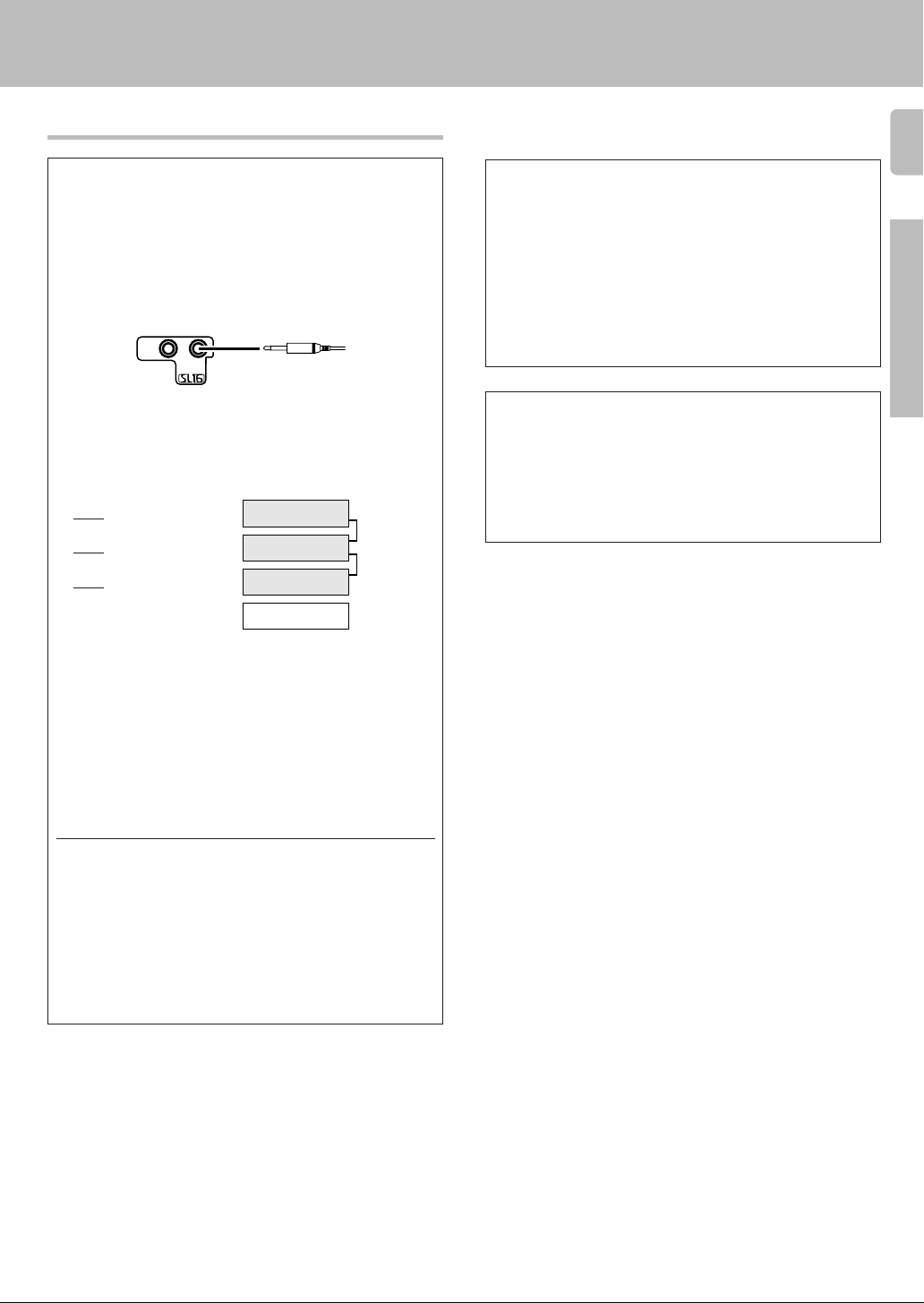
Connecting the system control
Connecting system control cords after connecting a KENWOOD
audio component system lets you take advantage of convenient
system control operations.
This unit is compatible only with the [SL-16] mode. The system
control operation is not available if the unit is connected in the
[XS8], [XS], or [XR] connection mode.
If your component has the mode select switch, set the connected
components to the [SL16] mode.
SYSTEM
CONTROL
SYSTEM CONTROL
cord
• You may connect the system control cord to either the left or right jack.
EXAMPLE: [SL16] mode connections
The underlined portion represents the setting of the system control
mode.
SL16]
[
SL16] [XS] [XS8] [XR]
[
SL16] [XS] [XS8]
[
Receiver
Cassette deck
or MD recorder
CD player
SYSTEM
CONTROL
cord
Setting up the system
SYSTEM CONTROL OPERATIONS
Remote Control
Lets you operate this unit with the system remote supplied with the
receiver.
Automatic Operation
When you start playback from a source component, the input selector
on this unit switches to that component automatically.
Synchronized Recording
Lets you synchronize recording with the start of playback when recording from CD, MD or analog discs.
Registering setup codes for KENWOOD audio components
If you own remote controllable KENWOOD audio components that are
not compatible with system control, registering the setup code enables
you to control those components using the remote control supplied with
this unit (without connecting system control cords). To register setup
codes for your remote controllable KENWOOD audio components, see
“Registering setup codes for other components”.
fi·
15
Preparations
[XS]
• In order to take advantage of the system control operations, the
components must be connected to the correct jacks. To use a CD
player it must be connected to the CD jacks. To use a cassette deck
(or MD recorder) it must be connected to the MD/TAPE jacks. When
using more than one CD player (etc.) only the one connected to the
specified jacks may be connected for system control.
• Some CD players and cassette decks are not compatible with the
[SL16] system control mode. Do not make system connections with
equipment that is not [SL16] compatible.
• Some MD players are not system control compatible. You cannot
make system control connections to this kind of equipment.
Notes
1. [SL16] equipment cannot be combined with [XR], [XS], and [XS8]
equipment for system operations. If your equipment consists of this
kind of combination, please do not connect any system control cords.
Even without system control cords, normal operations can be carried
out without effecting performance.
2. Do not connect system control cords to any components other than
those specified by KENWOOD. It may cause a malfunction and
damage your equipment.
3. Be sure the system control plugs are inserted all the way in to the
system control terminals.
Record player
Page 16

Connecting the speakers
16
Front Speakers A
Right
Setting up the system
Left
Preparations
FRONT SPEAKERS CENTER SPEAKER
RED BLUE GREEN
L
75µs
AM 10kHz
FM 100kHz
50µs
AM 9kHz
FM 50kHz
DEEMPHASIS
CHANNEL
SPACE
R
MONITOR
OUT
DVD
Center
Speaker
+
VIDEO 1
PLAY INPLAY INPLAY INREC OUTPLAY IN
VIDEO 3VIDEO 2VIDEO 1
RALC
B
LR
LR
SUB WOOFER
Powered
subwoofer
PRE OUT
FRONT SPEAKERS
+
SURROUND SPEAKERS
Right
Surround Speakers
(Be sure to connect both
surround speakers)
+
GRAYORANGE
Left
Use the FRONT SPEAKERS B
terminals if you want to connect
a second front speaker system.
Page 17

Connecting the terminals
1 Strip coating.
2 Loosen.
Setting up the system
Connection of banana plugs (For U.S.A. and Canada)
1 Secure.
2 Insert.
17
3 Insert. 4 Secure.
1 Strip coating.
3 Insert the cord. 4 Return the lever.
2 Push the lever.
• Sound will not be heard if the speaker terminal is not fully secured.
• Never short circuit the + and – speaker cords.
• If the left and right speakers are connected inversely or the speaker
cords are connected with reversed polarity, the sound will be unnatural with ambiguous acoustic imaging. Be sure to connect the speakers correctly.
Speaker impedance
After confirming the speaker impedance indications printed on the rear
panel of the receiver, connect speakers with matching impedance
ratings. Using speakers with a rated impedance other than that indicated on the rear panel of the receiver could result in malfunctions or
damage to the speakers or receiver.
Preparations
Page 18

18
Speaker placement
Preparations
Center speaker
Preparing the remote control
For VR-507 (RC-R0720)
Loading the batteries
1 Remove the cover.
2 Insert the batteries.
Setting up the system
Front
speaker
Surround
speaker
Subwoofer
Listening
position
Front speakers : Place to the front left and right of the listening position.
Front speakers are required for all surround modes.
Center speaker : Place front and center. This speaker stabilizes the
sound image and helps recreate sound motion. Be sure to connect a
center speaker when using the Dolby 3 Stereo mode.
Surround speakers : Place to the direct left and right, or slightly
behind, the listening position at even heights, approximately 1 meter
above the ears of the listeners. These speakers recreate sound motion
and atmosphere. Required for surround playback.
Subwoofer : Reproduces powerful deep bass sounds.
• Although the ideal surround system consists of all the speakers listed
above, if you don't have a center speaker or a subwoofer, you can
divide those signals between the available speakers in the speaker
settings steps to obtain the best possible surround reproduction from
the speakers you have available. (
Channel space switching
(Except for the USA, Canada, UK, Europe, and Australia)
The space between radio channels has been set to the one that prevails
in the area to which the system is shipped. However, if the current
channel space setting does not match the setting in the area where the
system is to be used, for instance when you move from area 1 or area
2 shown in the following table or vice versa, proper reception of AM/FM
broadcasts cannot be expected. In this case, change the channel space
setting in accordance with your area by referring to the following table.
3 Close the cover.
1
2
• Insert two AA-size (R6) batteries as indicated by the polarity markings.
For KRF-V7050D (RC-R0613)
Loading the batteries
1 Remove the cover.
3 Close the cover.
1
2
• Insert two AA-size (R6) batteries as indicated by the polarity markings.
2 Insert the batteries.
Operation
When the STANDBY indicator is lit, the power turns ON when you press
the POWER key on the remote control. When the power comes ON,
press the key you want to operate.
Operating range
(Approx.)
Remote sensor
Area
USA, Canada and South
1
American countries
2
Move switch lever to match your area with a small screwdriver or
other pointed tool.
Other countries
DEEMPHASIS
CHANNEL
SPACE
75µs
AM 10kHz
FM 100kHz
50µs
AM 9kHz
FM 50kHz
DEEMPHASIS
CHANNEL
SPACE
CHANNEL
Space Frequency
FM: 100 kHz
AM: 10 kHz
FM: 50 kHz
AM: 9 kHz
L
R
MONITOR
PLAY PLAY INPLAY INREC OUTPLAY IN
OUT
DVD
VIDEOVIDEO 2VIDEO 1
VIDEO 1
A
R
6 m
Infrared ray system
• When pressing more than one remote control key successively, press
the keys securely by leaving an interval of 1 second or more between
keys.
Notes
1. The supplied batteries may have shorter lives than ordinary batteries due
to use during operation checks.
2. When the remote-controllable distance gets shorter than before, replace
both batteries with new ones.
3. Placing the remote sensor in direct sunlight, or in direct light from a high
frequency fluorescent lamp may cause a malfunction.
In such a case, change the location of the system installation to prevent
malfunction.
Page 19

Preparing for surround sound
Speaker settings
To enable you to obtain optimum enjoyment from the receiver’s listening
modes, make sure to complete the speaker settings (subwoofer, front,
center, and surround speakers) as described below.
MULTI CONTROL
SET UP
POWER
(KRF-V7050)
Turn on the power to this receiver by pressing
1
POWER (
Select a speaker system.
2
1 Press the SET UP key such that the subwoofer setting
indication “SUBW ON” appears.
SP A
CLIP MUTE
RDS EON PTY
TP TA NEWS
2 Use the MULTI CONTROL knob or keys to select the appro-
priate subwoofer setting.
1 SUBW ON: Subwoofer setting mode to the receiver is ON.
2 SUBW OFF:
• The initial setting is “SUBW ON”.
• When the setting “SUBW OFF” is selected, the front speakers are
automatically set to “FRNT LRG” and the procedure skips to step 5.
• When subwoofer output sound is required, select “FRNT NML”.
3 Press the SET UP key to accept the setting.
• The front speakers setting indication “FRNT” appears.
SP A
CLIP MUTE
RDS EON PTY
TP TA NEWS
4 Use the MULTI CONTROL knob or keys to select the appropri-
ate front speakers setting.
1 FRNT NML (normal): Average size front speakers are
2 FRNT LRG (large): Large front speakers are con-
• For “FRNT LRG” selection, no sound will be heard from SUBW
even when it is set to ON. However, if you select CINEMA EQ when
subwoofer is selected, you will be able to hear sound from the
subwoofer.
When in STEREO mode, the sound goes directly to front speaker.
5 Press the SET UP key to accept the setting.
• The center speaker setting indication “CNTR” appears.
TI.VOLB
TI.VOLB
) key.
LFE
LFE
ON/STANDBY
SET UP
MULTI
CONTROL
RC-R0613
RC-R0720
FM
C
RL
SW
RSLS
S
Subwoofer setting mode to the receiver is OFF.
C
RL
SW
S
RSLS
connected to the receiver.
nected to the receiver.
AUTO SOUND
AM
PRO LOGIC
MHz
kHz
FM
AM
MHz
kHz
STEREO
3
DOWN MIX
AUTO SOUND
PRO LOGIC
STEREO
3
DOWN MIX
DIGITAL
S.DIRECT
MONITOR
DSP
DIGITAL
S.DIRECT
MONITOR
DSP
TUNED
TUNED
AUTO
MEMO
AUTO
MEMO
6 Use the MULTI CONTROL knob or keys to select the appropriate
19
center speaker setting.
If you selected “LRG” as the front speakers setting,
1 CNTR LRG (large): A large center speaker is connected to
2 CNTR NML (normal): An average size center speaker is con-
3 CNTR OFF: Center speaker setting mode to the
If you have selected “NML” as the front speakers setting,
1 CNTR ON: Center speaker setting mode to the receiver is
2 CNTR OFF: Center speaker setting mode to the receiver is
7 Press the SET UP key again to accept the setting.
• The surround speaker setting indication “SURR” appears.
8 Use the MULTI CONTROL knob or keys to select the appropriate
surround speaker setting.
If you selected “LRG” as the center speaker setting,
1 SURR LRG (large): Large surround speakers are con-
2 SURR NML (normal): Average size surround speakers are
3 SURR OFF: Surround speaker setting mode to the
If you have selected other than “LRG” as the center speaker
setting,
1 SURR ON: Surround speaker setting mode to the receiver
2 SURR OFF: Surround speaker setting mode to the receiver
ST.
9 Press the SET UP key again to accept the setting.
• The receiver enters the speaker volume level adjustment mode.
• In steps 3 and 4, indications appear only for the selected channels
of the speakers that require adjusting.
Adjust the speaker volume level.
3
From your usual listening position, adjust the volume levels. The
volume levels from each speaker should be the same.
1 Use the MULTI CONTROL knob or keys to adjust the volume
level of the test tone output from the speaker channel to be
adjusted.
The channel indication blinks while the test tone is being output.
TI.VOLB
SP A
CLIP MUTE
RDS EON PTY
TP TA NEWS
ST.
The test tone is heard from the speakers in the following
R
C
L
LFE
RSLS
S
sequence for 2 seconds each:
• If you change the volume level settings for the speakers while listening
to music, the settings referred to on this page are also changed.
• If the speaker setting selects are OFF, the speaker level settings are
reset.
2 Press the SET UP key.
• The test tone is turned off. The receiver enters the mode for inputting
the distance to the speakers.
the receiver.
nected to the receiver.
receiver is OFF.
ON.
OFF.
nected to the receiver.
connected to the receiver.
receiver is OFF.
is ON.
is OFF.
FM
AM
MHz
kHz
AUTO SOUND
PRO LOGIC
3
DOWN MIX
STEREO
DIGITAL
S.DIRECT
MONITOR
DSP
TUNED
AUTO
MEMO
ST.
•
Continued to next page
Preparations
Page 20

Preparing for surround sound
LFE
C
S
RSLS
TI.VOL
CLIP MUTE
RDS EON PTY
TP TA NEWS
L
SP A
R
SW
B
20
Input the distance to the speakers.
4
1 Measure the distance from the listening position to each of
the speakers.
Jot down the distance to each of the speakers.
Distance to front speakers: ____ feet (meters)
Distance to center speaker: ____ feet (meters)
Distance to surround speakers: ____ feet (meters)
2 Use the MULTI CONTROL knob or keys to select the dis-
tance to the front speakers.
The speaker indicator to be adjusted blinks.
FM
TI.VOLB
SP A
CLIP MUTE
RDS EON PTY
TP TA NEWS
C
L
R
SW
LFE
S
RSLS
AUTO SOUND
AM
PRO LOGIC
MHz
kHz
Indication in feet Indication in meters
• The allowable setting range is 1 to 30 feet (0.3 to 9.0 m), adjustable
in 1 foot (0.3 m) increments.
3 Press the SET UP key to accept the settings.
4 Repeat steps 2 and 3 to input the distance for each of the
speakers.
5 Setup is complete when the input indication reappears.
Operations
TI.VOLB
SP A
CLIP MUTE
RDS EON PTY
TP TA NEWS
C
L
R
LFE
SW
S
RSLS
Display when all speakers have been selected.
• The speakers you have selected should appear on the display.
Confirm that all the speakers have been correctly selected.
Input level adjustment (analog sources only)
If the input level of an analog source signal is too high, the CLIP
indicator will blink to indicate the source signal. Adjust the input level.
CLIP
RDS
TP
1 Use the INPUT SELECTOR knob to select the source of
which the input level you want to adjust.
• You can store a separate input level for each input source. If the
MONITOR function is ON, you can store an input level for when
MONITOR is on independently of the input levels for the input
sources.
2 Press the SOUND key repeatedly until the “INPUT” indication
appears.
Use the MULTI CONTROL knob or keys to adjust the input level.
3
FM
TI.VOLB
SP A
CLIP MUTE
RDS EON PTY
TP TA NEWS
C
L
R
LFE
SW
RSLS
S
• The adjustment mode is displayed for approximately eight
seconds.
• The input level may be adjusted to any one of three settings: 0dB,
-3dB, and -6dB. (The initial setting is 0dB.)
4 Press the SOUND key again to return to the input indication.
AUTO SOUND
AM
PRO LOGIC
MHz
kHz
DOWN MIX
STEREO
3
STEREO
DOWN MIX
STEREO
STEREO
3
DIGITAL
S.DIRECT
MONITOR
DSP
DIGITAL
S.DIRECT
MONITOR
DSP
AUTO
MEMO
TUNED
AUTO
MEMO
TUNED
Normal playback
Preparing for playback
Some preparatory steps are needed before starting playback.
INPUT MODE
ON/STANDBY
POWER
(KRF-V7050D)
ST.
SPEAKERS A/B
Selecting the input mode
If you have selected a component connected to the CD/DVD, VIDEO2,
VIDEO3 or DVD/6ch jacks, make sure that the input mode setting is
correct for the type of audio signal to be used. 9
Selecting MD/TAPE
Select the source name corresponding to the component connected
to the MD/TAPE jacks. The initial factory setting is “TAPE”. To change
the source to “MD,” follow the steps below:
1 Use the INPUT SELECTOR knob to select “TAPE”.
2 Hold down the AUTO/CINEMA EQ. key for more than 2
seconds.
• The source indication changes to “MD”.
• To return to the original indication, repeat procedure 2.
Selecting the speaker system
Press the SPEAKERS A or B key to select the speaker system
to be used.
A ON : Sound from the speakers connected to the SPEAKERS A
terminals on the rear panel.
B ON : Sound from the speakers connected to the SPEAKERS B
terminals on the rear panel. No sound will be heard from
the subwoofer.
A+B ON : Sound from both the speakers connected to the
SPEAKERS A and B terminals on the rear panel.
A+B OFF : No sound from the speakers. Use this setting when
listening with headphones for stereo sound in all playback
modes.
The indicator for the speakers
you want to use should be lit.
• Selecting “6ch INPT” by pressing the INPUT MODE key, whereby “DVD/
6ch” is the input source will cause SPEAKER A to be selected automatically.
ST.
Turning on the receiver
1 Turn on the power to the related components.
2 Turn on the power to this receiver by pressing POWER and
ON/STANDBY keys.
AUTO/CINEMA EQ.
INPUT SELECTOR
Page 21

Normal playback
Listening to a source component
INPUT SELECTOR
VOLUME
INPUT
SELECTOR
RC-R0720
Use the INPUT SELECTOR knob to select the source you
1
want to listen to.
The input sources change as shown below:
Selecting a source using the INPUT SELECTOR knob.
1 “ PHONO”
2 “ TUNER”
3 “ CD/DVD”
4 “TAPE” or “MD”
5 “ VIDEO1”
6 “ VIDEO2”
7 “ VIDEO3”
8 “ DVD/6ch”
9 “AV AUX”
Start playback from the selected source.
2
Use the VOLUME CONTROL knob or VOLUME keys to
3
adjust the volume.
VOLUME CONTROL
INPUT
SELECTOR
VOLUME
RC-R0613
Adjusting the sound
MULTI CONTROL
SOURCE DIRECT
SOUND
PHONES
MUTE
VOLUME
MULTI
CONTROL
BASS
BOOST
Adjusting the tone
You can adjust the sound quality when the receiver is in the PCM stereo
and analog stereo mode.
1 Press the SOUND key to select the tone mode to be adjusted.
BASS:Select this to adjust the low frequency range.
TREB: Select this to adjust the high frequency range.
SP A
CLIP MUTE
RDS EON PTY
TP TA NEWS
2 Use the MULTI CONTROL knob or keys to adjust the sound
quality.
• The bass and treble levels are adjustable from -10dB to +10dB in 2
step increments.
• The adjustment item is displayed for approximately 8 seconds.
SPEAKERS A/B
SOUND
RC-R0720
(Press the SOUND key once.)
(Press the SOUND key twice.)
TI.VOLB
C
L
R
LFE
SW
RSLS
S
VOLUME CONTROL
SOUND
MULTI
CONTROL
B. BOOST
VOLUME
MUTE
RC-R0613
FM
DIGITAL
AUTO SOUND
AM
PRO LOGIC
S.DIRECT
MHz
MONITOR
STEREO
3
DOWN MIX
TUNED
DSP
kHz
AUTO
MEMO
21
Operations
ST.
Once-touch low frequency emphasis (bass boost)
(remote control only)
You can adjust the sound quality when the receiver is in the PCM stereo
and analog stereo modes.
Press the B. BOOST or BASS BOOST key.
• Press the key once to select the maximum (+10dB) low frequency
emphasis setting.
• This key does not function when the receiver is in the sound quality or
ambience effects adjustment mode.
Switching back to the previous setting
Press the B. BOOST or BASS BOOST key again.
Page 22

Normal playback
22
Muting the sound
The MUTE key lets you mute the sound of the speakers.
Press the MUTE key.
TI.VOLB
To cancel
SP A
MUTE
CLIP
RDS EON PTY
TP TA NEWS
Blinks
LFE
C
L
R
SW
RSLS
S
Press the MUTE key again so that the “MUTE” indicator goes off.
• MUTE ON can also be deactivated by turning the volume control
knob.
SOURCE DIRECT playback (for analog input sources only)
Use this function to pass the source material direct to the amplifier,
bypassing any audio processing.
Press the SOURCE DIRECT key.
AUTO SOUND
PRO LOGIC
STEREO
3
DOWN MIX
DIGITAL
S.DIRECT
MONITOR
DSP
AUTO
MEMO
ST.
TUNED
FM
AM
MHz
kHz
• When you press the LISTEN MODE, SOUND, or SET UP keys,
Operations
or switch to another input source, SOURCE DIRECT playback will
be canceled.
• If CINEMA EQ. is switched ON, SOURCE DIRECT key will not be
effective.
• If SOURCE DIRECT is switched ON, CINEMA EQ. function will not
be effective.
To cancel
Press the SOURCE DIRECT key again.
• If SOURCE DIRECT playback was activated while in surround mode,
canceling SOURCE DIRECT playback will reactivate the previous
surround mode.
Listening with headphones
1 Press the SPEAKERS A or B key so that the speaker indica-
tor goes off.
Make sure the SPEAKERS
indicators are turned off.
TI.VOLB
SP A
CLIP MUTE
RDS EON PTY
TP TA NEWS
• If you turn off all of the speakers when in surround mode, the
surround mode will be canceled as well, resulting in stereo playback.
2 Connect headphones to the PHONES jack.
PHONES
LFE
RL
C
RSLS
S
Recording
Recording audio (analog sources)
MONITOR
INPUT SELECTOR
Recording a music source
1 Use the INPUT SELECTOR knob to select the source (other
than “MD/TAPE”) you want to record.
2 Set the cassette deck or MD recorder to record.
3 Start playback, then start recording.
Recording tapes or MD (with MONITOR function)
MONITOR = MD/TAPE recording
1 Press the MONITOR key.
FM
AM
MHz
kHz
2 Use the INPUT SELECTOR knob to select a source other than
“MD/TAPE”.
3 Start playback on the cassette deck connected to the
MONITOR jacks and start recording on the cassette deck or
MD recorder connected to the MD/TAPE jacks.
MD/TAPE = MONITOR recording
1 Use the INPUT SELECTOR knob to select “MD/TAPE.”
2 Start playback on the cassette deck connected to the MD/TAPE
jacks and start recording on the cassette deck or MD recorder
connected to the MONITOR jacks.
• To copy tapes using a double cassette deck, refer to the
instruction manual of the double cassette deck.
MONITOR function (analog sources only)
You can connect a cassette deck or graphic equalizer to the MONITOR
jacks of the receiver. If a graphic equalizer is connected, the MONITOR
key should be left in the on position. Alternately, if a cassette deck
equipped with a 3-head system is connected to the MONITOR jacks,
you will be able to monitor the just-recorded signal while making
recordings on the cassette deck. By switching the MONITOR key on
and off, you can compare the sound of the source signal and the justrecorded signal. For more information, refer to the instruction manual of
the connected component.
DIGITAL
AUTO SOUND
PRO LOGIC
S.DIRECT
STEREO MONITOR
3
DOWN MIX
DSP
AUTO
MEMO
ST.
TUNED
3 Use the VOLUME CONTROL knob or VOLUME keys to adjust
the volume.
Page 23

PRO LOGIC
FM
AM
PRO LOGIC
Recording
Listening to radio broadcasts
Recording video
1 Use the INPUT SELECTOR to select the video source (other than
“VIDEO1”) you want to record.
2 Set the video deck connected to VIDEO 1 to record.
• Select the REC MODE to record a digital input source.
3 Start playback, then start recording.
• Recording may not be normal for some video software. This is due to
the copy guard condition. t
Recording audio (digital sources)
Switch on the REC mode to record a digital input source.
Usually use the A-REC (Auto-Record) mode to record audio input
sources. When the digital mode changes during recording in the A-REC
mode, the audio input source may be interrupted momentarily.
Recording music in A-REC or M-REC mode
DIMMER
INPUT SELECTOR
1 Use the INPUT SELECTOR knob to select the source (CD/
DVD, DVD/6ch, VIDEO2 or VIDEO3) you want to record.
2 Set the cassette deck or MD recorder to record.
3 Press and hold the DIMMER key for more than 2 seconds to
select the A-REC or M-REC mode.
• The mode changes every 2 seconds as shown below.
1 Rec mode off : The digital input record mode is
2 A-REC : The digital input signals (DTS,
3 M-REC : The input signal type at the moment
For A-REC mode:
For M-REC mode:
4 Start playback, then start recording.
• If the audio reproduction stops in the middle due to change in the
input signals, etc., press the DIMMER key.
switched off.
Dolby Digital, or PCM) are identified
automatically and converted into
stereo signals that are ready for
recording.
this mode is selected is held
throughout this mode.
DIGITAL
FM
AUTO SOUND
PRO LOGIC
AM
MHz
kHz3 DOWN MIX
FM
AUTO SOUND
PRO LOGIC
AM
MHz
kHz3 DOWN MIX
FM
AUTO SOUND
PRO LOGIC
AM
MHz
kHz3 DOWN MIX
FM
AUTO SOUND
AM
PRO LOGIC
MHz
kHz3 DOWN MIX
STEREO
STEREO
STEREO
STEREO
S.DIRECT
MONITOR
DSP
DIGITAL
S.DIRECT
MONITOR
DSP
DIGITAL
S.DIRECT
MONITOR
DSP
DIGITAL
S.DIRECT
MONITOR
DSP
TUNED
TUNED
AUTO
MEMO
TUNED
AUTO
MEMO
TUNED
AUTO
MEMO
AUTO
MEMO
The receiver can store up to 40 stations in the memory and recall them by
one-touch operation.
23
Tuning radio stations
MULTI CONTROL
INPUT SELECTOR
BAND AUTO/CINEMA EQ
MULTI
CONTROL
BAND
AUTO
TUNER
RC-R0613
RC-R0720
Use the INPUT SELECTOR knob or TUNER key to select the
1
tuner.
Use the BAND key to select the desired broadcast band.
2
Each press switches the band
as follows:
1 FM
2 AM
Use the AUTO/CINEMA EQ. key to select the desired
3
tuning method.
“AM” or “FM” indicator
appears in the display
AUTO SOUND
FM
DIGITAL
AM
S.DIRECT
PRO LOGIC
MONITOR
MHz STEREO
3
DOWN MIX
DSP
kHz
AUTO
MEMO
TUNED
ST.
Each press switches the tuning method as follows:
1 AUTO lit (auto tuning)
2 AUTO not lit (manual tuning)
ST.
“AUTO” indicator lights up
in the display.
AUTO SOUND
FM
AM
PRO LOGIC
3
MHz STEREO
kHz
DOWN MIX
DIGITAL
S.DIRECT
MONITOR
DSP
AUTO
MEMO
TUNED
ST.
• Normally, set to “AUTO” (auto tuning). If the radio waves are weak
and there is a lot of interference, switch to manual tuning. (With
ST.
ST.
ST.
manual tuning, stereo broadcasts will be received in monaural.)
Use the MULTI CONTROL knob or keys to select the
4
station.
Frequency
display
“ST.” lights when a broadcast
is being received in stereo.
“TUNED” is displayed when a
station is received.
AUTO SOUND
FM
AM
PRO LOGIC
MHz STEREO
3
kHz
DOWN MIX
DIGITAL
S.DIRECT
MONITOR
DSP
AUTO
MEMO
TUNED
ST.
Auto tuning : The next station is tuned automatically.
Manual tuning : Turn the knob (press the key) to select the
desired station.
Operations
Page 24

Listening to radio broadcasts
Presetting radio stations manually
24
MULTI CONTROL
MEMORY
Tune to the station you want to store.
1
Press the MEMORY key while receiving the station.
2
Proceed to step 3 within 5 seconds.
(If more than 5 seconds elapse, press the MEMORY key again).
Use the MULTI CONTROL knob to select one of the station
3
presets (1 – 40).
Operations
Press the MEMORY key again to confirm the setting.
4
• Repeat steps 1, 2, 3, and 4 to store as many stations as necessary.
• If you store a station at a previously used preset, the old station will
Blinks for 5 seconds Lights for 5 seconds
TI.VOLB
SP A
CLIP MUTE
RDS EON PTY
TP TA NEWS
C
RL
LFE
SW
SRSLS
be replaced by the new one.
AUTO SOUND
FM
AM
PRO LOGIC
MHz STEREO
3
kHz
DOWN MIX
DIGITAL
S.DIRECT
MONITOR
DSP
TUNED
AUTO
MEMO
Receiving preset stations in order
P.CALL
4 / ¢
(P.CALL)
TUNER
RC-R0613
RC-R0720
Press TUNER key to select the tuner as the source.
ST.
1
Use the P.CALL
2
• Each time you press the key, another preset station is received in
order.
Pressing the P.CALL ¢ does the following:
Pressing the P.CALL 4 does the following:
Holding down the ¢ or 4 key, lets you skip through the
presets, receiving each preset station at 0.5 second intervals.
4/ ¢
key to select the desired station.
Receiving preset stations
Numeric keys
TUNER
RC-R0613
RC-R0720
Press TUNER to select tuner as the source.
1
Enter the number of the preset station you want to receive
2
(up to “40”).
Press the numeric keys in the following order:
For “15”, press .......... 0,5
For “20”, press .......... 0,0,)
• If you make a mistake entering a two digit number, press the +10 key
repeatedly to return to the original display and start again.
DIGITAL
AUTO SOUND
SP A
CLIP MUTE
RDS EON PTY
TP TA NEWS
TI.VOLB
C
RL
LFE
SW
SRSLS
FM
AM
PRO LOGIC
3
MHz STEREO
DOWN MIX
kHz
S.DIRECT
MONITOR
AUTO
ST.
TUNED
DSP
Page 25

Ambience effects
This receiver is equipped with listening modes that allow
you to enjoy an enhanced sonic ambience with a variety of
video sources.
In order to obtain the optimum effect from the surround
modes, make sure to input the proper speaker settings
beforehand. (
Surround modes
DTS
The DTS multi-channel audio format is available on CD, LD and DVD
software. DTS is a strictly digital format and can not be decoded inside
most CD, LD or DVD players. For this reason, if you attempt to listen to
DTS encoded software through the analog output of your new CD, LD
or DVD player, you will experience digital noise in most cases. This noise
can be quite loud if the analog output is connected directly to a high
power amplification system. Proper measures for playing the digital
output as described below should be taken to avoid this situation. To
enjoy DTS Digital Surround playback, an external 5.1 channel DTS
Digital Surround decoder system or an amplifier with a built-in DTS
Digital Surround decoder must be connected to the digital output (S/P
DIF, AES/EBU or TosLink) of a CD, LD or DVD player.
All models are incorporated with the DTS decoder.
Dolby Digital
The Dolby Digital surround format lets you enjoy up to 5.1 channels
of digital surround sound from Dolby Digital program sources (such
as Laserdisc or DVD software marked
previous Dolby surround, Dolby Digital provides even better sound
quality, greater spatial accuracy, and improved dynamic range.
Note
Although a full set of speakers (front left, right, and center, surround
left and right, and a subwoofer) is required for true 5.1 channel Dolby
Digital surround sound, this receiver lets you enjoy Dolby Digital (and
Dolby Surround) program sources, even if you connect only the front
speakers.
Center speaker
Subwoofer (SW)*
Front speakers (L, R)
Surround speakers (L, R)
). Compared with
25
Center speaker
Subwoofer (SW)*
Front speakers (L, R)
Surround speakers (L, R)
* Optional in this mode.
* LFE = Low Frequency Effects. This channel delivers separate
non-directional bass signals to the subwoofer for more dynamic
deep bass sound effects.
DTS has a .1 or LFE channel.
The indication “LFE” appears in the display when a signal is
being input for this channel.
Manufactured under license from Digital Theater
Systems, Inc. US Pat. No. 5,451,942 and other
worldwide patents issues and pending.
“DTS” and “DTS Digital Surround” are trademarks
of Digital Theater Systems, Inc.
© 1996 Digital Theater Systems, Inc. All rights
reserved.
Manufactured under license from Dolby Laboratories. Dolby, Pro Logic
and the double-D symbol are trademarks of Dolby Laboratories.
Confidential Unpublished Works. ©1992-1999 Dolby Laboratories, Inc.
All rights reserved.
* LFE = Low Frequency Effects. This channel delivers separate non-
directional bass signals to the subwoofer for more dynamic deep bass
sound effects.
Although only Dolby Digital soundtracks incorporate a separate low
frequency channel, connecting a subwoofer will also improve deep
bass performance in the other surround modes.
The indication “LFE” appears in the display when a signal is being
input for this channel.
Dolby 3 Stereo
Dolby 3 Stereo is available for systems that do not have surround
speakers. When in the Dolby 3 Stereo mode, the surround information
is redirected to the front left and right speakers. This mode is designed
for use with Dolby Surround program sources, but can also improve
sound field unity for programs that are not Dolby Surround encoded.
Dialog positioning and sound image definition, however, may not be as
accurate when used with programs that are not Dolby Surround
encoded.
Center speaker
Subwoofer (SW)
Front speakers (L, R)
Operations
“Circle Surround and the
in the United States and selected foreign countries. Circle Surround
technology is incorporated under license from SRS Labs, Inc”.
®
symbol are trademarks of SRS Labs, Inc.
Page 26

Ambience effects
26
Dolby PRO LOGIC II
Dolby Pro Logic II was designed specifically to provide a new sense of
spatiality, directionality and articulation of sounds from Dolby Surround
encoded sources (such as video and Laserdisc software marked
logic design, a matrix surround decoding and the decoding of stereo, full
bandwidth surround outputs. The PRO LOGIC II modes programmed
into this receiver are “MOVIE”, “MUSIC” and “PRO LOGIC”. The “MOVIE”
mode of the PRO LOGIC II has preset characteristics to produce a
calibrated, high-level surround sound playback while the “MUSIC”
mode has user-adjustable characteristics to offer the three optional
controls, like “Dimension”, “Center Width” and “Panorama mode” to
allow optimization of the soundfields as desired. The “Dimension”
control allows the user to gradually adjust the soundfield either towards
the front or towards the rear; the “Center Width” control allows various
adjustment of the left-center-right speakers’ balance; the “Panaroma
mode” extends the front stereo image to include the surround speakers
for an exciting “wraparound” effect with side wall imaging.
Operations
). This is achieved with an intelligent, built-in feedback
Center speaker
Subwoofer (SW)
Front speaker (L, R)
Surround speakers (L, R)
Multi channel music (SRS Circle Surround)
SRS Circle surround enables you to listen to multi channel sound from
the stereo source. We assume you have already enjoyed listening to
Dolby digital sound/DTS multi channel sound with your multi speakers.
Now, this time try listening to the stereo source (ex. Audio CD) using your
multi speakers. You may discover a new type of “stereo” sound through
SRS Circle Surround.
DSP mode
The DSP mode lets you add the atmosphere of a live concert or hall to
almost any type of program source. These modes are particularly effective
when used with stereo program sources, like CD, television, and FM radio.
You might enjoy trying the ARENA, JAZZ CLUB, THEATER, STADIUM or
DISCO mode the next time you watch a concert or sporting event!
Center speaker
Subwoofer (SW)
Front speakers (L, R)
Surround speakers (L, R)
What's DSP?
DSP stands for Digital Signal Processor.
The way a sound is heard in an actual environment depends on a variety
of different factors. One of the most important is reverberation (the act
of decaying elements of sound echoing in various places).
The DSP modes produce the feeling of presence by using the DSP to
create reverberation, without spoiling the sound quality of the original
signal.
DVD 6-channel mode
Using a DVD player or the like equipped with six (5.1) output channels
and the receiver, you can enjoy multi-channel encoded DVD source
material in all its splendor. Since the source signals are digital and each
channel is input independently, the resulting sound quality, sense of
spaciousness, and dynamic range are superb.
Center speaker
Center speaker
Subwoofer (SW)
Front speakers (L, R)
Surround speakers (L, R)
Subwoofer (SW)*
Front speakers (L, R)
Surround speakers (L, R)
* LFE = Low Frequency Effects. This channel delivers separate non-
directional bass singnals to the subwoofer for more dynamic deep
bass sound effects.
Page 27

Surround play
SL
The DTS compatible models can reproduce a CD, DVD, or LD carrying
the DTS mark.
DOLBY DIGITAL can be used when playing DVD or LD software bearing
the
DOLBY PRO LOGIC and DOLBY 3 STEREO can be used when playing
video, DVD, or LD software bearing the
Preparations
• Turn ON related components.
• Complete “Preparing for surround sound” (speaker settings).(
• Use the INPUT SELECTOR to select the component you wish to play
• Use the INPUT MODE key to select the input mode (analog or digital)
• Noise will be produced when a DTS source is played by selecting the
Start playing the video software.
1
Press the LISTEN MODE or LSTN M. key to select the
2
listening mode.
The listening mode settings are stored separately for each input. If the
input mode is set to digital auto (“AUTO SOUND” lights), the receiver
selects the optimal listening mode automatically based on the type of
input signal and the speaker settings.
Each press of the LISTEN MODE or LSTN M. key switches the
setting as listed below.
The listening mode settings are different depending on the type
of input signal.
mark and DOLBY DIGITAL format digital broadcasts (etc.).
mark.
INPUT MODE
INPUT SELECTOR
LISTEN MODE
LSTN M.
INPUT
SELECTOR
RC-R0720
back with surround sound.
for the source you wish to play back. 9
analog input.
RC-R0613
Ambience effects
When the DOLBY DIGITAL signal is input:
(The DOLBY DIGITAL, PROLOGIC, or 3 STEREO indicator lights up.)
1 DOLBY DIGITAL: DOLBY DIGITAL surround
2 PL II MOVIE: PRO LOGIC II surround MOVIE mode
(The PRO LOGIC indicator lights up.)
3 PL II MUSIC: PRO LOGIC II surround MUSIC mode
(The PRO LOGIC indicator lights up.)
4 PRO LOGIC: PRO LOGIC II surround PRO LOGIC mode
(The PRO LOGIC indicator lights up.)
5 3 STEREO: 3-STEREO mode
(The 3 STEREO indicator lights up)
6 STEREO: Normal stereo playback
When you select DOLBY DIGITAL
“DOLBY DIGITAL” will be scrolled from right to left.
TI.VOLB
SP A
CLIP MUTE
RDS EON PTY
TP TA NEWS
RCL
SWLFE
SRSRSL
S
FM
AUTO SOUND
PRO LOGIC
AM
STEREO
MHz
kHz3 DOWN MIX
DIGITAL
S.DIRECT
MONITOR
DSP
When the DTS signal is input:
(The DTS indicator lights up.)
1 DTS: DTS surround
2 STEREO: Normal stereo playback
When the analog signal or the digital signal (except for
DOLBY DIGITAL or DTS signal) is input:
1 PL II MOVIE: PRO LOGIC II surround MOVIE mode
(The PRO LOGIC indicator lights up.)
2 PL II MUSIC: PRO LOGIC II surround MUSIC mode
(The PRO LOGIC indicator lights up.)
3 PRO LOGIC: PRO LOGIC II surround PRO LOGIC mode
(The PRO LOGIC indicator lights up.)
4 3 STEREO: 3-STEREO mode
(The 3 STEREO indicator lights up.)
5 CIRCLE SURROUND: CS 5.1 surround
(The CS 5.1 indicator lights up.)
6 ARENA: DSP Surround ARENA mode.
7 JAZZ CLUB: DSP Surround JAZZ CLUB mode.
8 THEATER: DSP Surround THEATER mode.
9 STADIUM: DSP Surround STADIUM mode.
0 DISCO: DSP Surround DISCO mode.
- STEREO: Normal stereo playback. Sound is produced
from the two front channels only.
• If Dolby Digital or DTS signal having more channels than the
maximum number of playback channels available using the
receiver’s current settings is input, the DOWNMIX indicator on
the front panel lights up and downmixing is performed to match
the number of available channels.
Adjust the volume.
3
Notes
• Depending on the type of the signal or speaker setting, some listening
modes cannot be selected.
• When playback is started, the sound may be cut or interrupted before
the input source is confirmed as Dolby Digital.
• To enjoy Dolby Digital surround (as well as all the other listening
modes) from a single component, be sure to use a Dolby Digital
compatible source component. Connect the Dolby Digital compatible
source component's Dolby Digital format digital audio signal to one of
the DIGITAL INPUT jacks on the back of the receiver. Connect the
normal audio signal correctly to the respective component's AUDIO
jacks. 0!@#
TUNED
AUTO
MEMO
27
ST.
Operations
Page 28

Ambience effects
DVD 6-channel playback
28
Using a DVD player or the like equipped with six (5.1) output channels and
the receiver, you can enjoy surround sound playback.
When you try to play a disc other than Dolby Digital such as DTS CD, no
sound is produced or, noise may be heard. To avoid this situation, make
sure that you connect the component to the receiver’s DVD/6ch. INPUT
jacks through a surround processor which can decode the surround
signal you want to listen to.
Connecting a DVD player which can decode the surround signal itself is
also acceptable.
INPUT MODE
Operations
RC-R0720
Preparations
• Connect your DVD player to the DVD/6ch jacks of the receiver.
• Turn on all other components that will be used.
• Complete “Preparing for surround sound”. (
Select “DVD/6ch” as the input source.
1
• If speaker system B is on when “DVD/6ch” is selected as the input
source, it switches off and speaker system A turns on automatically.
Select "6ch INPT" by pressing the INPUT MODE key.
2
Start playback of the DVD software.
3
Adjust the volume.
4
• It is not possible to adjust the volume level or sound quality (SET UP,
SOUND) of the channels separately when the receiver is in the DVD/
6ch mode. Adjust the volume with the controls of the DVD player.
For the powered subwoofer, you can adjust the volume of the
subwoofer using the subwoofer’s own volume control.
INPUT SELECTOR
DVD
RC-R0613
Convenient functions
MULTI CONTROL
DIMMER
SOUND
SOUND
MULTI
CONTROL
RC-R0613
RC-R0720
Adjusting the sound
You can make further adjustments to the sound while listening to playback
in the surround mode.
1 Press the SOUND key until the desired item appears in the
display.
Each time you press the button, the menu changes as follows:
Note that some items are not displayed in certain modes.
1 BASS (low frequency range sound quality adjustment -
PCM and analog stereo mode only) ¡
2 TREB (high frequency range sound quality adjustment -
PCM and analog stereo mode only) ¡
3 C (center speaker level adjustment)
4 SR (right surround speaker level adjustment)
5 SL (left surround speaker level adjustment)
6 SW (subwoofer level adjustment)
7 INPUT (input level adjustment - analog mode only) )
8 NIGHT (midnight mode on/off - Dolby Digital mode only)
9 CINEMA or MUSIC (Circle surround mode only)
0 PANORAMA (panorama mode on/off)*
- DIMENSION (dimension adjustment)*
= CENTER WIDTH (center width adjustment)*
* Pro Logic II Music mode only
2 Use the MULTI CONTROL knob or keys to adjust the setting as
desired.
• The adjustment item is displayed for approximately 8 seconds.
Page 29

Ambience effects
Midnight mode (Dolby Digital mode only)
When watching movies at night , you might not be able to raise the volume
as loud as normal. Midnight mode compresses the dynamic range of
previously specified parts of the Dolby Digital sound track (like scenes
with sudden increases in volume) to minimize the difference in volume
between the specified and non-specified parts. This makes it easy to hear
all of the sound track, even when listening at low volumes.
1 Press the SOUND key repeatedly until “NIGHT” appears on the
display.
• This can be selected only if CD/DVD, DVD/6ch, VIDEO2 or VIDEO3
is selected as the source and the listen mode is set to “DOLBY
DIGITAL.”
2 Use the MULTI CONTROL knob or keys to select the ON or
OFF setting.
SP A
CLIP MUTE
RDS EON PTY
TP TA NEWS
TI.VOLB
RCL
LFE
S
SRSL
AUTO SOUND
PRO LOGIC
AM
MHz
kHz
DOWN MIX
3
STEREO
S.DIRECT
MONITOR
DSP
TUNED
AUTO
MEMO
ST.
FM
DIGITAL
• The adjustment item is displayed for approximately 8 seconds.
• Some Dolby Digital software may not be compatible with the Midnight
mode.
Circle surround mode
When you enjoy multi sound from the stereo source (Circle Surround),
you can select the circle surround mode.
1 Press the LISTEN MODE or LSTN M. key repeatedly until
“CIRCLE SURROUND” appears on the display.
2 Press the SOUND key repeatedly until “CINEMA” or “MUSIC”
appears on the display.
3 Use the MULTI CONTROL knob or keys to select “CINEMA”
(for movies) or “MUSIC” (for music).
Panorama mode (Pro Logic II music mode only)
When listening to music, you will be able to enjoy the “wraparound”
sound effect when you adjust the panorama mode.
1 Press the SOUND key repeatedly until “PANORAMA” appears
on the display.
• The PANORAMA setting indication scrolls across the display.
“PANORAMA” will be scrolled from right to left.
B
SP A
CLIP
RCL
SW
S
SRSL
2 Use the MULTI CONTROL knob or keys to select
PANORAMA ON or OFF.
1 ON :PANORAMA mode is ON.
2 OFF :PANORAMA mode is OFF.
B
SP A
CLIP
RCL
SW
S
SRSL
AUTO SOUND
PRO LOGIC
AUTO SOUND
PRO LOGIC
DIGITAL
DIGITAL
Dimension mode (Pro Logic II music mode only)
When listening to music with certain recordings, you will also be able to
achieve a suitable balance from all the speakers by adjusting the
dimension mode.
1 Press the SOUND key repeatedly until “DIMENSION”
appears on the display.
• The DIMENSION indication scrolls across the display.
2 Use the MULTI CONTROL knob or keys to adjust the
soundfield towards the rear or the front.
Soundfield is adjusted towards the front.
AUTO SOUND
SP A
CLIP
B
RCL
SW
S
SRSL
PRO LOGIC
DIGITAL
G
Soundfield is in neutral postion.
B
SP A
CLIP
RCL
SW
S
SRSL
AUTO SOUND
PRO LOGIC
DIGITAL
G
Soundfield is adjusted towards the rear.
B
SP A
CLIP
RCL
SW
S
SRSL
Center width mode (Pro Logic II music mode only)
Center width adjustment allows you to enjoy an enchanced sound when
listening to music through center image from only center speaker, or left
and right speakers or various combinations adjustments.
1 Press the SOUND key repeatedly until “CENTER WIDTH”
appears on the display.
• The CENTER WIDTH indication scrolls across the display.
• When the center speaker is switched OFF, this mode will not
be effective.
2 Use the MULTI CONTROL knob or keys to adjust the left-
center-right output.
Center image will be heard from center speaker only.
B
SP A
CLIP
Center image will be heard from left and right speakers only.
B
SP A
CLIP
• When in other postions, center image from center speaker, left and
right speakers can be heard simultaneously with various
combinations.
RCL
SW
S
SRSL
RCL
SW
S
SRSL
AUTO SOUND
PRO LOGIC
AUTO SOUND
PRO LOGIC
AUTO SOUND
PRO LOGIC
DIGITAL
DIGITAL
DIGITAL
29
Operations
Page 30

30
Subwoofer adjustment
It is easy to adjust the volume of the subwoofer using the remote
control.
1 Press the SOUND key repeatedly until “SW” appears on the
display.
FM
TI.VOLB
SP A
CLIP MUTE
RDS EON PTY
TP TA NEWS
RCL
LFE
SW
S
SRSL
AM
MHz
kHz
AUTO SOUND
PRO LOGIC
3
DOWN MIX
2 Use MULTI CONTROL knob or keys to adjust the volume.
•The adjustment range is –10 dB to +10 dB.
Display dimmer adjustment
The dimmer function lets you select the brightness of the receiver's
display. You might find this useful if you darken your room to watch movies
or listen to music.
Each time you press the DIMMER key, the display brightness
changes among the three available settings. Select the
brightness level you find most pleasing.
TI.VOLB
Operations
SP A
CLIP MUTE
RDS EON PTY
TP TA NEWS
RCL
LFE
SW
S
STEREO
AUTO SOUND
FM
AM
PRO LOGIC
MHz
STEREO
kHz3 DOWN MIX
DIGITAL
S.DIRECT
MONITOR
DSP
TUNED
DIGITAL
S.DIRECT
MONITOR
DSP
AUTO
MEMO
Ambience effects
ST.
AUTO
MEMO
ST.
TUNED
DIGITAL
AUTO SOUND
SP A
CLIP MUTE
RDS EON PTY
TP TA NEWS
SP A
CLIP MUTE
RDS EON PTY
TP TA NEWS
TI.VOLB
TI.VOLB
RCL
LFE
SW
S
RCL
LFE
SW
S
FM
PRO LOGIC
AM
STEREO
MHz
kHz3 DOWN MIX
AUTO SOUND
FM
PRO LOGIC
AM
STEREO
MHz
kHz3 DOWN MIX
S.DIRECT
MONITOR
DSP
DIGITAL
S.DIRECT
MONITOR
DSP
TUNED
TUNED
96kHz LPCM playback
The receiver is compatible with the 96kHz LPCM playback. To play a
96kHz DVD, set the listen mode to “STEREO”.
• When “96kHz” appears in the display, press the LISTEN MODE key
(the listen mode changes to the STEREO mode).
AUTO
MEMO
AUTO
MEMO
ST.
ST.
Page 31

Basic remote control operations for other components
(For VR-507)
The remote control supplied with this receiver) is also capable
of controlling components from a variety of manufacturers once
you register the appropriate setup codes into the remote control
unit.
Low battery warning
Replace all two batteries with new ones when you notice a shortening
of the distance from which the remote control will operate. The remote
control is designed to retain setup codes in memory while you change
batteries.
Registering setup codes for other components (RC-R0720)
Repeat steps 2 to 4 to register additional components
5
until all components have been registered.
Notes
• Although each setup code is designed to work with a number of
different models, certain codes may not work with some models.
(Also, certain codes may only operate some of the functions available
on a given model.)
• In case the code for TV/VCR combos does not work, enter the TV
code and the VCR code respectively after checking the codes (See
“Searching for your code”).
• For TV/VCR combos – if there is no separate TV code listed, enter the
code, enter “9-9-3,” and press VCR key instead.
31
SET UP
Source
keys
RC-R0720
Find the setup code of the component to be registered.
1
• Refer to the setup code lists to find the setup code for the component
to be registered. fi
Example: To register a DVD made by KENWOOD, you would enter
“0534”.
Input Component Maker Code Key
(DVD) DVD player KENWOOD 0534 DVD
Press the source key (DVD, CBL, VCR, TV, DSS, CD,
2
RECEIVER).
Press and hold the SET UP key until the LED blinks twice,
3
then release the SET UP key.
Press the numeric key to enter the first four-digit code for
4
the component.
• If performed correctly, the LED will blink twice.
• Point the remote control at the component and press POWER key
once. It should turn ON/OFF but if it does not repeat step 2 to 4.
• If the component still does not work, try searching for the code.¤
• If the component does not have a POWER key, press PLAY key
instead.
LED
POWER
Numeric keys
Programming TV/VCR combo control
Perform the following instructions to control a TV/VCR Combo:
Turn on the TV/VCR Combo and insert a video cassette.
1
• Read steps 2 to 4 completely before proceeding. You may want to
highlight or write down the code for the component you wish to
program before moving onto step 2.
Press the VCR key once. Next, press and hold the SET UP
2
key until the LED blinks twice, then release the SET UP
key.
Use the setup codes for TV/VCR Combos to locate the
3
brand name, then press the numeric key to enter the first
four-digit code for your component.
• If performed correctly, the LED will blink twice.
• If the LED did not blink twice, repeat steps 2 through 3 and try
entering the same code again.
Point the remote control at the component and press the
4
POWER key once.
• It should turn off. If it does not respond, repeat steps 2 through 3,
trying each code for your component until you find one that works.
• If it still does not work, try searching for the code, see “Searching for
your code”. ¤
• If the device does not have a POWER key, press PLAY key instead.
If you have located a setup code that works, but it has a
5
separate TV code, you will also need to program it into
the remote control to access the volume control as
follows:
1 Press the TV key once.
• The LED will blink twice.
2 Press the numeric key to enter the TV code for your TV/VCR
combo.
• If the code is correct, the LED will blink twice.
If there is no separate TV code listed, you will need to
perform the following steps to access the volume control:
1 Press and the hold SET UP key until the LED blinks twice,
then release the SET UP key.
2 Press the numeric key to enter “9 - 9 - 3” .
• The LED will blink twice.
3 Press the VCR key once.
•The LED will blink twice.
Operations
fl
Page 32

Basic remote control operations for other components
Searching for your code
32
If your component does not respond after trying all the codes listed for your
component, or if your component is not listed at all, try searching for your
code.
For example, to search for a code for your TV:
Press the TV key once. Next, press and hold the SET UP
1
key until the LED blinks twice, then release the SET UP
key.
Press the numeric key to enter “9 - 9 - 1”.
2
• The LED will blink twice.
Point the remote control at the TV and slowly alternate
3
between pressing the POWER and TV keys.
• Stop when the TV turns ON/OFF.
• In the search mode, the remote control will send IR codes from its
library to the selected device, starting with the most popular code first.
Press the SET UP key once to lock in the code.
4
To search for the codes of your other components, repeat
5
steps
1
through 4, but substitute the appropriate key
(i.e., DVD, CBL, VCR, TV, DSS, CD or RECEIVER) for the
component you are searching for.
Operations
Checking the codes
If you have set up the remote control using the procedures described in
“Searching for your codes”, you may need to find out which four-digit
code is operating your equipment:
For example, to find out which code is operating your TV:
Re-assigning device keys
The remote control can be set up to control a second TV or VCR, or any
combination of eight home entertainment components.
For example, to control a TV, a Cable Converter, and two VCRs using the
remote control,you will need to re-assign the unused CD key to operate the
second VCR as follows:
Press and hold the SET UP key until the LED blinks twice,
1
then release the SET UP key.
Press the numeric key to enter “9 - 9 - 2”.
2
• The LED will blink twice.
Press the VCR key once, then press the CD key once.
3
To re-assign other device keys, repeat steps 1 through
4
3
by substituting the key sequence from the below chart
for the most popular components:
To re-assign key
Sequence Perform
TV as 2nd VCR key SETUP - 9 - 9 - 2 - VCR -TV
TV as 2nd CBL key SETUP - 9 - 9 - 2 - CBL - TV
TV as 2nd RECEIVER key SETUP - 9 - 9 - 2 - RECEIVER - TV
TV as 2nd CD key SETUP - 9 - 9 - 2 - CD - TV
TV back to TV SETUP - 9 - 9 - 2 - TV - TV
VCR as 2nd TV key SETUP - 9 - 9 - 2 - TV - VCR
VCR as 2nd CBL key SETUP - 9 - 9 - 2 - CBL- VCR
VCR as 2nd RECEIVER key SETUP - 9 - 9 - 2 - RECEIVER - VCR
VCR as 2nd CD key SETUP - 9 - 9 - 2 - CD - VCR
VCR back to VCR SETUP - 9 - 9 - 2 - VCR - VCR
• When a re-assignment is done, the LED will blink twice to confirm your
choice. At that time, you will need to program the remote control in
order to control the new component.
Press the TV key once. Next, press and hold the SET UP
1
key until the LED blinks twice, then release the SET UP
key.
Press the numeric key to enter “9 - 9 - 0”.
2
• The LED will blink twice.
To view the code for the first digit, press “1” once. Wait
3
for 3 seconds, count the number of times the LED blinks
(e.g., blinks = 3) and write down that number.
• If a code digit is “0”, the LED will not blink.
Repeat step 3 three more times for the remaining digits.
4
Use “2” for the second digit, “3” for the third digit, and
“4” for the fourth digit.
To check the codes of your other components, repeat
5
steps
1
through 4, but substitute the appropriate key
(i.e., DVD, CBL, VCR, TV, DSS, CD or RECEIVER) for the
component you are checking.
• As suggested earlier on, write down each of the four- digit code.
Page 33

Basic remote control operations for other components
Changing volume lock
The remote control is set to control volume of a component through your
TV while in the TV, VCR, or Cable mode. However, in an Audio mode (i.e.
CD), you have separate control of your audio component’s volume. If your
TV is not remote controllable, or if you want volume to be controlled by a
different component, you can change the Volume Lock setting to control a
volume through a non-associated mode (e.g.,through the cable in the TV
mode).
To change Volume Lock to the another mode:
1 Press and hold the SET UP key until the LED blinks twice, then
release the SET UP key.
2 Press the numeric key to enter “9 - 9 - 3”, then press any mode key
once (except TV).
• The LED will blink twice.
3 At this point, whenever you press the VOLUME +/– keys, or the
MUTE key, volume will be controlled by your mode choice.
4 To unlock, press the SET UP key until the LED blinks twice, and
press the numeric key to enter “9-9-3”, then press the VOLUME
+ key.
• The LED will blink 4 times upon being unlock.
To change Volume Lock back to the TV mode:
1 Press and hold the SET UP key until the LED blinks twice, then
release the SET UP key.
2 Press the numeric key to enter “9 - 9 - 3”, then press the TV
key.
• The LED will blink twice.
3 At this point, whenever you press the VOLUME +/– keys, or
MUTE key, volume will be controlled by your TV.
4 To unlock, press the TV key, then the SET UP key until the
LED blinks twice, and press the numeric key to enter “9-9-3”,
then press the VOLUME – key.
• The LED will blink 4 times upon being unlock.
Operating other components
This operation lets you operate the registered components.
KENWOOD audio components with system control turn on and off
automatically with the receiver via the system control connections.
Source
keys
SET UP
RC-R0720
Use the input selector keys to select the component you
1
desire.
• Pressing the input selector keys also changes the input selector on
the receiver.
• When you operate your registered TV, VCR, or DVD player, go
to step 2.
• When you operate the CD player, Cassette deck, MD player, or
Tuner with system control connection, go to step 3.
Press the source key.
2
Press the operation keys you desire.
3
• To return to the receiver operation mode, press the RECEIVER key.
Notes
• Be sure to point the remote control at the remote sensor on the
receiver when you want to operate KENWOOD components connected by system control cords. Otherwise, point the remote control
at the component you want to operate.
• To initialize the remote control, press the SET UP key until the LED
blinks twice. Then press the numeric key to to enter “9-8-0”. The LED
blinks twice.
Source key Other components
TV TV
VCR VCR, Audio Cassette, DVD, LD, DAT
CBL Cable, Video Accessories, DSS, Satellite
DVD VCR, Audio Cassette, DVD, LD
DSS Satellite, DSS, CABLE, Video Accessories
CD CD, Home Automation, MD, Amplifier, Tuner,
Miscellaneous Audio
POWER
RECEIVER
Numeric keys
w
33
Remote Control
Page 34

(For KRF-V7050D)
34
The remote control supplied with this receiver is also
capable of controlling components from a variety of
manufacturers once you register the appropriate setup
codes into the remote control unit.
Low battery warning
Replace all two batteries with new ones when you notice a shortening
of the distance from which the remote control will operate. The remote
control is designed to retain setup codes in memory while you change
batteries.
Registering setup codes for other components (RC-R0613)
POWER
Numeric
keys
Source
POWER
keys
Basic remote control operations for other components
Repeat steps 2 to 3 to register additional components
4
until all components have been registered.
Note
Although each setup code is designed to work with a number of different
models, certain codes may not work with some models. (Also, certain
codes may only operate some of the functions available on a given
model.)
Operating other components
This operation lets you operate the registered components.
KENWOOD audio components with system control turn on and off
automatically with the receiver via the system control connections.
RECEIVER
(RC-R0613)
POWER
Source
POWER
keys
Find the setup code of the component to be registered.
1
• Refer to the setup code lists to find the setup code for the component
to be registered. ·
Example: To register a DVD made by KENWOOD, you would enter
“805”.
Input Component Maker Code Key
(DVD) DVD player KENWOOD 805, 808 DVD
Remote Control
Hold down the POWER key and press the numeric keys to
2
enter the setup code.
• Example: Press “805” to register a DVD player made by KENWOOD.
• If you push an invalid key, the remote will exit the setup mode.
Press the source POWER (TV, VCR, DVD, CABLE, DSS)
3
key for more than 2 seconds, and check to see that the
component you want to control turns on.
If the component does not react, and there is more than one
setup code, enter another setup code and try again.
• If the component is already on, pressing the source POWER keys for
more than 2 seconds will turn it off.
Use the input selector keys to select the component you
1
desire.
• Pressing the input selector keys also changes the input selector on
the receiver.
• When you operate your registered TV, VCR, DVD player, Cable
tuner, or DSS receiver, go to step 2.
• When you operate the CD player, Cassette deck, MD player, or
Tuner with system control connection, go to step 3.
Press the source POWER key.
2
Press the operation keys you desire.
3
• To return to the receiver operation mode, press the RECEIVER key.
The remote control mode returns to the receiver operation mode
when you do not operate for more than 15 seconds.
Note
Be sure to point the remote control at the remote sensor on the receiver
when you want to operate KENWOOD components connected by
system control cords. Otherwise, point the remote control at the component you want to operate.
w
Page 35

Setup code chart (for VR-507 (RC-R0720))
TV Setup codes
AOC 0030, 0019
Admiral 0093, 0463
Aiko 0092
Akai 0030
Alaron 0179
Ambassador 0177
America Action 0180
Ampro 0751
Anam 0180
Audiovox 0451,0180, 0092, 0623
Baysonic 0180
Belcor 0019
Bell & Howell 0154, 0016
Bradford 0180
Brockwood 0019
Broksonic 0236, 0463
CXC 0180
Candle 0030, 0056
Carnivale 0030
Carver 0054
Celebrity 0000
Cineral 0451, 0092
Citizen 0060, 0030, 0056, 0039,
Concerto 0056
Contec 0180
Craig 0180
Crosley 0054
Crown 0180, 0039
Curtis Mathes 0047, 0054, 0154, 0051,
Daewoo 0451, 0019, 0039, 0092,
Daytron 0019
Denon 0145
Dumont 0017,0019
Dwin 0720, 0774
Electroband 0000
Emerson 0154, 0236, 0463, 0180,
Envision 0030
Fisher 0154
Fujitsu 0179
Funai 0180, 0179, 0171
Futuretech 0180
GE 0047, 0051, 0451, 0093,
Gibralter 0017, 0030, 0019
GoldStar 0030, 0178, 0019, 0056
Gradiente 0053, 0056
Grunpy 0180, 0179
Hallmark 0178
Harley Davidson 0179
Harman/Kardon 0054
Harvard 0180
Hitachi 0145, 0056, 0016, 0151
Infinity 0054
Inteq 0017
JBL 0054
JCB 0000
JVC 0053
0092
0451, 0093, 0060, 0030,
0145, 0056, 0016, 0039,
0166, 0466, 1147, 1347
0623, 0624
0282, 0178, 0019, 0179,
0039, 0177, 0623, 0624
0282, 0178, 0021, 0135,
1147, 1347
Maker Setup codes Maker Setup codesMaker Setup codes
KEC 0180
KTV 0180, 0030, 0039
Kenwood 0030, 0019
LG 0056
LXI 0047, 0054, 0154, 0156,
Logik 0016
Luxman 0056
MGA 0150, 0030, 0178, 0019
MTC 0060, 0030, 0019, 0056
Magnavox 0054, 0030, 0179
Majestic 0016
Marantz 0054, 0030
Matsushita 0250
Megatron 0178, 0145
Memorex 0154, 0250, 0463, 0150,
Midland 0047, 0017, 0051, 0039,
Minutz 0021
Mitsubishi 0093, 0150, 0178, 0019
Motorola 0093
Multitech 0180
NAD 0156, 0178, 0166
NEC 0030, 0019, 0056
NTC 0092
Nikko 0030, 0178, 0092
Onwa 0180
Optimus 0154, 0250, 0166
Optonica 0093, 0165
Orion 0236, 0463, 0179
Panasonic 0051, 0250
Penney 0047, 0156, 0051, 0060,
Philco 0054, 0463, 0030, 0145,
Philips 0054
Pilot 0030, 0019, 0039
Pioneer 0166
Portland 0019,0039, 0092
Prism 0051
Proscan 0047
Proton 0178, 0466
Pulsar 0017, 0019
Quasar 0051, 0250, 0165
RCA 0047, 0051, 0093, 0019,
Radio Shack 0047, 0154, 0165, 0180,
Realistic 0154, 0165, 0180, 0030,
Runco 0017, 0030, 0603
SSS 0180, 0019
Sampo 0030, 0039
Samsung 0060, 0030, 0178, 0019,
Samsux 0039
Sansei 0451
Sansui 0463
Sanyo 0154
Scimitsu 0019
Scotch 0178
Basic remote control operations for other components
0178
0178, 0179, 0056, 0016
0135
0030, 0178, 0021, 0019,
0056, 0039, 0135, 1347
0019
0090, 0135, 1047, 1147,
1247, 1347
0030, 0178, 0019, 0056,
0039
0178, 0019, 0056, 0039
0056
Scott 0236, 0180, 0178, 0019,
Sears 0047, 0054, 0154, 0156,
Semivox 0180
Semp 0156
Sharp 0093, 0165, 0039
Shogun 0019
Signature 0016
Sony 0000
Soundesign 0180, 0178, 0179
Squareview 0171
Starlite 0180
Supreme 0000
Sylvania 0054, 0030
Symphonic 0171
TMK 0178, 0056, 0177
Tandy 0093
Technics 0051, 0250
Technol Ace 0179
Techwood 0051, 0056
Teknika 0054, 0180, 0150, 0060,
Telefunken 0056
Toshiba 0154, 0156, 0060
Totevision 0039
Vector Research 0030
Victor 0053
Vidikron 0054
Vidtech 0178, 0019
Wards 0054, 0165, 0030, 0178,
White Westinghouse
Yamaha 0030, 0019
Zenith 0017, 0463, 0016, 0092,
0179
0178, 0179, 0056, 0171
0019, 0179, 0056, 0016,
0039, 0092
0021, 0019, 0179, 0056,
0016
0463, 0623, 0624
0624
35
Remote Control
Page 36

Setup code chart (for VR-507 (RC-R0720))
36
VCR Setup codes
Admiral 0048,0209
Adventura 0000
Aiko 0278
Aiwa 0037, 0000
Akai 0041
America Action 0278
American High 0035
Asha 0240
Audiovox 0037
Beaumark 0240
Bell & Howell 0104
Broksonic 0184, 0121, 0209, 0002
CCE 0072, 0278
Calix 0037
Canon 0035
Carver 0081
Cineral 0278
Citizen 0037, 0278
Colt 0072
Craig 0037, 0047, 0240, 0072,
CurtisMathes 0060, 0035, 0041, 0162
Cybernex 0240
Daewoo 0045, 0278
Denon 0042
Dynatech 0000
Electrohome 0037
Electrophonic 0037
Emerex 0032
Emerson 0037, 0184, 0000, 0121,
Fisher 0047, 0104
Fuji 0035, 0033
Funai 0000
GE 0060, 0035, 0048, 0240
Garrard 0000
Go Video 0526
GoldStar 0037, 0038
Gradiente 0000
Remote Control
HI-Q 0047
Harley Davidson 0000
Harman/Kardon 0081, 0038
Harwood 0072
Headquarter 0046
Hitachi 0000, 0042, 0041
Hughes Net. Sys. 0042
JVC 0067, 0041
Jensen 0041
KEC 0037, 0278
KLH 0072
Kenwood 0067, 0041, 0038
Kodak 0035, 0037
LXI 0037
Lloyd’s 0000
Logik 0072
MEI 0035
MGA 0240, 0043
MGN Technology 0240
MTC 0240, 0000
Magnasonic 0278
Magnavox 0035, 0039, 0081, 0000,
Magnin 0240
Marantz 0035, 0081
0271
0043, 0209, 0002, 0278
0149
Maker Setup codes Maker Setup codesMaker Setup codes
Marta 0037
Matsushita 0035, 0162, 0454
Memorex 0035, 0037, 0048, 0039,
Minolta 0042
Mitsubishi 0048, 0067, 0043
Motorola 0035, 0048
Multitech 0000, 0072
NEC 0104, 0067, 0041, 0038
Nikko 0037
Noblex 0240
Olympus 0035
Optimus 0037, 0048, 0104, 0162,
Orion 0184, 0209, 0002
Panasonic 0035, 0162, 0225, 0454,
Penney 0035, 0037, 0240, 0042,
Pentax 0042
Philco 0035, 0209
Philips 0035, 0081
Pilot 0037
Pioneer 0067
Polk Audio 0081
Profitronic 0240
Proscan 0060
Protec 0072
Pulsar 0039
Quarter 0046
Quartz 0046
Quasar 0035, 0162, 0454, 1162
RCA 0060, 0035, 0048, 0240,
Radio Shack 0000
Radix 0037
Randex 0037
Realistic 0035, 0037, 0048, 0047,
Runco 0039
STS 0042
Samsung 0240, 0045
Sanky 0048, 0039
Sansui 0000, 0067, 0209, 0041,
Sanyo 0047, 0240, 0104, 0046
Scott 0184, 0045, 0121, 0043
Sears 0035, 0037, 0047, 0000,
Semp 0045
Sharp 0048
Shintom 0072
Shogun 0240
Singer 0072
Sony 0035, 0032, 0000, 0033
Sylvania 0035, 0081, 0000, 0043
Symphonic 0000
TMK 0240
Tatung 0041
Teac 0000, 0041
Technics 0035, 0162
Teknika 0035, 0037, 0000
Thomas 0000
Basic remote control operations for other components
0047, 0240, 0000, 0104,
0209, 0162, 0046, 0454,
1162, 1262
0454, 1062, 1162, 1262
1064, 1162, 1262
0038
0042, 0149
0000, 0104, 0046
0271
0042, 0104, 0046
Toshiba 0045, 0043
Totevision 0037, 0240
Unitech 0240
Vector 0045
Vector Research 0038
Video Concepts 0045
Videosonic 0240
Wards 0060, 0035, 0048, 0047,
White Westinghouse
XR-1000 0035, 0000, 0072
Yamaha 0038
Zenith 0039, 0000, 0209, 0033
0081, 0240, 0000, 0042,
0072, 0149
0209, 0072, 0278
TV/VCR combos Setup codes
Maker Setup codes
American High 0035 (for TV use 0051)
Brocksonic 0002, 0294,
Colt 0072
Curtis Mathis 0035 (for TV use 0051)
Daewoo 0278
Emerson 0002, 0294, 0479
Funai 0000
GE 0035 (for TV use 0051),
Hitachi 0035 (for TV use 0051),
HQ 0000
Lloyds 0000
MGA 0240
Magnavox 0081 (for TV use 0054),
Magnin 0240
Memorex 0037,
Mitsubishi 0048 (for TV use 0093)
Orion 0002, 0294, 0479
Panasonic 0035 (for TV use 0051),
Penney 0035 (for TV use 0051),
Quasar 0035 (for TV use 0051),
RCA 0060 (for TV use 0047),
Sansui 0000, 0479
Sanyo 0240
Sears 0000, 0037
Sharp 0048 (for TV use 0093)
Sony 0032 (for TV use 0000)
Symphonic 0000
Zenith 0000
0060 (for TV use 0047),
0048 (for TV use 0093),
0240
0000
0035 (for TV use 0051),
0000
0162 (for TV use 0250)
0162 (for TV use 0250)
0240,
0162 (for TV use 0250)
0162 (for TV use 0250)
0035 (for TV use 0051),
0048 (for TV use 0093)
Page 37

Basic remote control operations for other components
Setup code chart (for VR-507 (RC-R0720))
Cable tuner Setup codes
Maker Setup codes Maker Setup codes
ABC 0003, 0008, 0014, 0017,
Allegro 0153, 0315
Archer 0153, 0797
Bell & Howell 0014
Century 0153
Citizen 0153, 0315
Comtronics 0040
Contec 0019
Eastern 0002
Emerson 0797
Everquest 0015,0040
Focus 0400
Garrard 0153
Gemini 0015
General Instrument 0476, 0276, 0011, 0810
GoldStar 0144, 0040
Goodmind 0797
Hamlin 0020, 0259, 0009, 0034
Hitachi 0011
Hytex 0007
Jasco 0015, 0153, 0315
Jerrold 0003, 0012, 0476, 0276,
Memorex 0000
Movie Time 0063
NSC 0063
Oak 0019, 0007
Optimus 0021
Panasonic 0000, 0107, 0021
Paragon 0000
Philips 0153
Pioneer 0144, 0533, 0877
Popular Mechanics0400
Pulsar 0000
Quasar 0000
RCA 0021
Radio Shack 0015, 0315, 0797, 0883
Recoton 0400
Regal 0020, 0259
Regency 0002
Rembrandt 0011
Runco 0000
SL Marx 0040
Samsung 0144, 0040
Scientific Atlanta 0008, 0477, 0017, 0877
Signal 0015,0040
Signature 0011
Sprucer 0021
Starcom 0003, 0015
Stargate 0015, 0040, 0797
Starquest 0015
TV86 0063
Teleview 0040
Tocom 0012, 0013
Toshiba 0000
Tusa 0015
Unika 0153
United Artists 0007
Universal 0153, 0191
Viewstar 0063
Zenith 0000, 0525
Zentek 0400
0007, 0011, 0013
0014, 0015, 0011, 0810
DBS/DSS receiver Setup codes
Maker Setup codes
AlphaStar 0772
Chaparral 0216
Echostar 0775
Expressvu 0775
General Instrument 0627, 0361, 0869
HTS 0775
Hitachi 0819
Hughes Net. Sys. 0749
JVC 0775
Jerrold 0627, 0361
Magnavox 0724, 0722
Memorex 0724
Next Level 0869
Panasonic 0701
Philips 0724, 0722
Primestar 0627, 0361
RCA 0566, 0143, 0392, 0855
Radio Shack 0869
Realistic 0052
Sony 0639
Star Choice 0869
Toshiba 0749, 0790
Uniden 0724, 0722, 0052
Zenith 0856
Receiver Setup codes
ADC 0531
Adcom 0616
Aiwa 0158, 0189, 0121, 0405
Akai 0224
Capetronic 0531
Carver 0189, 0008, 0042, 0360
Casio 0195
Clarinette 0195
Curtis Mathes 0080
Denon 0004
Emerson 0424
Fisher 0042, 0219, 0360
Garrard 0463, 0424
Harman/Kardon 0110, 0189, 0891
JBL 0110
JVC 0074
Kenwood 0027, 0186, 0042, 0077,
Koss 0424
LXI 0181
Linn 0189
Lloyd’s 0195
MCS 0039, 0346
Magnavox 0531, 0189, 0195, 0391
Marantz 0039, 0189
Modulaire 0195
NAD 0320
Nakamichi 0097, 0347
Onkyo 0135
Optimus 0531, 0670, 0186, 0080,
Panasonic 0039, 0309
Penney 0195
Philips 0189, 0391
Pioneer 0531, 0014, 0150, 0630,
Quasar 0039
RCA 0531, 0054, 0346, 0360,
Realistic 0195, 0163, 0181
Sansui 0189, 0346
Sanyo 0219, 0801
Scott 0163, 0322
Sharp 0186
Sherwood 0491, 0502
Sony 0158, 0168, 0474
Soundesign 0670
Teac 0463, 0163
Technics 0039, 0309, 0208
Victor 0074
Wards 0158, 0014, 0189, 0080,
Yamaha 0176, 0186
Yorx 0195
Zenith 0857
1570
0042, 0177, 0181, 0219,
0738, 0801, 1023
0080, 1023
0530, 1023
0054
37
Remote Control
Page 38

Setup code chart (for VR-507 (RC-R0720))
38
CD player Setup codes
Aiwa 0157, 0124
Burmester 0420
California Audio Lab
Carver 0157, 0179, 0437
DKK 0000
Denon 0003, 0873
Emerson 0305
Fisher 0179, 0174
Garrard 0420, 0393
Genexxa 0032, 0305
Harman/Kardon 0157, 0173
Hitachi 0032
JVC 0072
Kenwood 0028, 0037, 0190, 0626,
Krell 0157
LXI 0305
Linn 0157
MCS 0029
MTC 0420
Magnavox 0157, 0305
Marantz 0029, 0157, 0180
Mission 0157
NSM 0157
Nikko 0174
Onkyo 0101, 0868
Optimus 0000, 0032, 0179, 0305,
Panasonic 0029, 0303
Parasound 0420
Philips 0157, 0626
Pioneer 0032, 0305, 0468, 0244
Polk Audio 0157
Proton 0157
QED 0157
Quasar 0029
RCA 0179, 0305, 0053, 0764
Realistic 0179, 0420, 0180
Remote Control
Rotel 0157, 0420
SAE 0157
Sansui 0157, 0305
Sanyo 0179
Scott 0305
Sears 0305
Sharp 0037, 0180, 0861
Sherwood 0180
Sony 0000, 0185, 0490
Soundesign 0145
Tascam 0420
Teac 0420, 0393, 0174, 0180
Technics 0029, 0303
Victor 0072
Wards 0157, 0053
Yamaha 0036, 0187
Yorx 0461
0029, 0303
0681, 0826
0037, 0420, 0145, 0468,
0437
DVD player Setup codes
Maker Setup codes Maker Setup codesMaker Setup codes
Demon 0490
GE 0522
Harman/Kardon 0582
JVC 0558
Kenwood 0534
Magnavox 0503
Marantz 0539
Mitsubishi 0521
Onkyo 0503
Optimus 0571
Panasonic 0490
Philips 0503, 0539
Pioneer 0525, 0571
Proscan 0522
RCA 0522
Samsung 0573
Sony 0533
Technics 0490
Theta Digital 0571
Toshiba 0503
Yamaha 0490, 0545
Zenith 0503, 0591
LD player Setup codes
Maker Setup codes
Denon 0059
Mitsubishi 0059
NAD 0059
Pioneer 0059
Sony 0193, 0201
Cassette deck Setup codes
Maker Setup codes
Aiwa 0029, 0197
Carver 0029
Denon 0076
Harman/Kardon 0182, 0029
JVC 0244, 0273
Kenwood 0070
Magnavox 0029
Marantz 0029
Onkyo 0135, 0282
Optimus 0027, 0220
Panasonic 0229
Philips 0029
Pioneer 0027, 0220, 0099
Polk Audio 0029
Sansui 0029
Sony 0243, 0170, 0291
Technics 0229
Victor 0273
Wards 0027
Yamaha 0097, 0094
Basic remote control operations for other components
DBS/DSS audio service Setup codes
Aiwa 0010, 0159, 0404
Fisher 0052
Harman/Kardon 0477
JBL 0477
JVC 0073
Jerrold 0459, 0520
RCA 0056
Scientific Atlanta 0460
Sony 0010, 0159
Starcom 0459
Stereo Amplifier Setup codes
Maker Setup codes
Aiwa 0406
Carver 0269
Curtis Mathes 0300
Denon 0160
Harman/Kardon 0892
JVC 0331
Linn 0269
Magnavox 0269
Marantz 0269
Panasonic 0308
Philips 0269, 0892
Pioneer 0013, 0300
Polk Audio 0269, 0892
RCA 0300
Sony 0220, 0689
Technics 0308
Victor 0331
Wards 0013
Yamaha 0354
Home Automation Setup codes
Maker Setup codes
GE 0240
Lutron 0597
One For All 0167
Radio Shack 0240
Security System 0167
Universal X10 0167
X10 0167
Page 39

Setup code chart (for KRF-V7050D (RC-R0613))
TV Setup codes
Maker Setup codes
SONY 101
GE/RCA 102
RCA 103, 104, 105,
106, 117
ZENITH 107, 108
MAGNAVOX 109
SHARP 110
PANASONIC 111,112, 122
SAMSUNG 109
JVC 113
HITACHI 114, 115
PIONEER 116
PROSCAN 117
QUASAR 118
PHILIPS 109
SANYO 119
TOSHIBA 120
MITUBISHI 121
LOEWE 123, 124
VCR Setup codes
Maker Setup codes
SONY 301, 302, 303,
GE/HITACHI 307
RCA/HITACHI 308
PANASONIC 309, 310
MAGNAVOX 311, 312, 313
TOSHIBA 314
MITSUBISHI 315, 316, 317,
SHARP 319, 320
G.E 321
ZENITH 322
GOLD STAR 323
JVC 324, 325, 326,
PHILIPS 313
HITACHI 328, 329
SANYO 330
TOSHIBA 331
Basic remote control operations for other components
DVD Setup codes
Maker Setup codes
304, 305, 306
318
327
JVC 801
SONY 802
PIONEER 803
PANASONIC 804
KENWOOD 805, 808
TOSHIBA 806
PHILIPS 807
39
CABLE Setup codes
Maker Setup codes
JERROLD 201, 202
S.ATLANTA 203
ZENITH 204, 205
PIONEER 206, 207
TOCOM 208
G.I. 209
HAMLIN 210, 211
OAK 212, 213, 214
MACOM 215, 216, 217
GEMINI 218
PHILIPS 219, 220
PANASONIC 221, 222
SAMSUNG 223
DSS Setup codes
Maker Setup codes
RCA 901
G.I. 902
ECHOSTAR 903
TOSHIBA 904
PANASONIC 905
HUGHES 906
SONY 907
HITACHI 908
PRIMESTAR 909
Remote Control
Page 40

Basic remote control operations for other components
CASSETTE deck, CD player & MD recorder operations
40
You can perform these basic operations using the keys described below when connected to KENWOOD cassette
deck, MD recorder or CD player equipped with system control operations. %
Cassette deck operations keys
Remote Control
1 (Rewind)
2 (Play)
SET UP
DVD CBL VCR TV
DSS
MUTE
+
VOLUME
GUIDE
SETUP
P.CALL
4
REC M.
INFO/OSD
16¡
REC
¶78
DISC SEL.
POWER
RECEIVER
CD
123
456
789
0
+10
ENTER
¢
LISN.M
+
LAST
SOUND
DVD
CHANNEL
SLEEP
CINE.EQ
4
INPUT
EXIT/RETURN
MULTI CONTROL
MULTI CONTROL
TUNERPHONO MD/TAPE CD/DVD
VIDEO2VIDEO1 VIDEO3 DVD
DISC SKIP
SELECT
BAND
AUTO
BASS BOOST
A/B +100
AV AUX
P.CALL
DIM.
MENU
RC-R0720
¢
6 (Play)
¡ (Fast forward)
8 (Pause)
7 (Stop)
1 (Rewind)
¡ (Fast forward)
1
23
456
789
RETURN
0 +10
SET UP SOUND
P.CALL
B.BOOST
RECEIVER
PHONO CD/DVD
VIDEO1 VIDEO2
MUTE VOLUME
TUNING
DVD
A/B+100
DISC SKIP
TV SEL.
LSTN M.
DSS
OSDMENU
MULTI CONTROL
ENTER
CINE.EQ
AUTO
INPUT SEL.TITLE
TUNER
DISC SEL.
VIDEO3
RC-R0613
POWER
P.CALL
POWER
TV
VCR
DVD
CABLE
BAND
DVD
MD/TAPE
CHANNEL
AV AUX
6 (3 Play)
7 (Stop)
Page 41
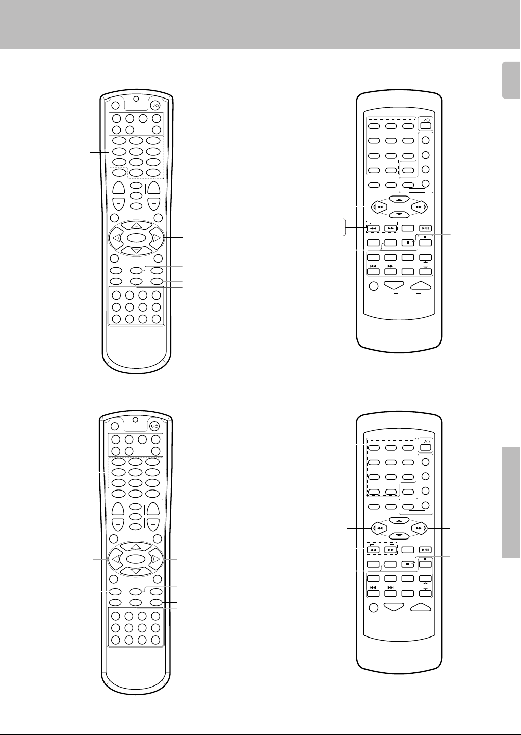
Basic remote control operations for other components
CD player operation keys
SET UP
DVD CBL VCR TV
DSS
Numeric keys
(Select tracks)
MUTE
+
VOLUME
GUIDE
SETUP
P.CALL
4
4 (Skip down)
REC M.
INFO/OSD
16¡
REC
¶78
DISC SEL.
POWER
RECEIVER
CD
123
456
789
0
+10
ENTER
¢
LSTN.M
+
LAST
SOUND
DVD
CHANNEL
SLEEP
CINE.EQ
4
INPUT
EXIT/RETURN
MULTI CONTROL
MULTI CONTROL
TUNERPHONO MD/TAPE CD/DVD
VIDEO2VIDEO1 VIDEO3 DVD
DISC SKIP
SELECT
BAND
AUTO
BASS BOOST
A/B +100
AV AUX
P.CALL
¢
DIM.
MENU
¢ (Skip up)
6 (Play/Pause)
8 (Pause)
7 (Stop)
Numeric keys
(Select tracks)
4 (Skip down)
1 (Search)
¡ (Search)
DISC SKIP
1
23
456
789
RETURN
0+10
SET UP SOUND
LSTN M.
DSS
OSDMENU
P.CALL
MULTI CONTROL
TUNING
ENTER
CINE.EQ
A/B+100
DVD
DISC SKIP
TV SEL.
AUTO
INPUT SEL.TITLE
TUNER
DISC SEL.
VIDEO3
B.BOOST
RECEIVER
PHONO CD/DVD
VIDEO1 VIDEO2
MUTE VOLUME
POWER
P.CALL
POWER
TV
VCR
DVD
CABLE
BAND
DVD
MD/TAPE
CHANNEL
AV AUX
¢ (Skip up)
6 (3 Play)
7 (Stop)
41
RC-R0720
MD recorder operation keys
SET UP
DVD CBL VCR TV
DSS
CD
123
Numeric keys
(Select tracks)
4 (Skip down)
1 (Backward Search)
456
789
MUTE
+
VOLUME
GUIDE
MULTI CONTROL
SETUP
P.CALL
4
REC M.
MULTI CONTROL
INFO/OSD
16¡
REC
¶78
TUNERPHONO MD/TAPE CD/DVD
VIDEO2VIDEO1 VIDEO3 DVD
DISC SKIP
DISC SEL.
0
LSTN.M
LAST
SOUND
SLEEP
CINE.EQ
INPUT
SELECT
BAND
AUTO
BASS BOOST
RC-R0613
POWER
RECEIVER
Numeric keys
(Select tracks)
1
456
789
+10
ENTER
¢
+
DVD
CHANNEL
4
EXIT/RETURN
P.CALL
¢
4 (Skip down)
1¥¡ (1¥¡ Search)
¢ (Skip up)
+100 (+100)
AV AUX
A/B +100
DIM.
MENU
6 (3 Play)
¡ (Forward Search)
8 (Pause)/+100 (+100)
7 (Stop)
0+10
OSDMENU
SET UP SOUND
P.CALL
TUNING
A/B+100
B.BOOST
DISC SKIP
RECEIVER
TV SEL.
PHONO CD/DVD
DVD
VIDEO1 VIDEO2 VIDEO3
MUTE VOLUME
23
RETURN
LSTN M.
DSS
POWER
P.CALL
MULTI CONTROL
ENTER
CINE.EQ
AUTO
INPUT SEL.TITLE
TUNER
DISC SEL.
POWER
TV
VCR
DVD
CABLE
BAND
DVD
MD/TAPE
CHANNEL
AV AUX
¢ (Skip up)
6 (3 Play)
7 (Stop)
Remote Control
RC-R0720
RC-R0613
Page 42

Basic remote control operations for other components
Other components’ operations
42
Refer to the following for the type of remote control operations available for each component.
1 Select the input source.
2 Press the keys corresponding to the operations you desire.
Refer to the following sections for details.
These keys can be used to perform the basic operations of KENWOOD and other makers’ components
which the setup code for each component had been entered beforehand. ⁄›
TV operation keys
POWER
RECEIVER
CD
0
+10
ENTER
¢
LSTN.M
+
LAST
SOUND
DVD
CHANNEL
SLEEP
CINE.EQ
4
INPUT
EXIT/RETURN
MULTI CONTROL
SELECT
MULTI CONTROL
BAND
AUTO
TUNERPHONO MD/TAPE CD/DVD
VIDEO2VIDEO1 VIDEO3 DVD
A/B +100
POWER
CHANNEL +/–
(Channel +/–)
INPUT
P.CALL
¢
SELECT (Select)
DIM.
MENU
Numeric keys
MUTE (Mute)
VOLUME +/–
(Volume +/–)
GUIDE
INFO/OSD
SET UP
DVD CBL VCR TV
DSS
123
456
789
MUTE
+
VOLUME
GUIDE
SETUP
P.CALL
4
REC M.
INFO/OSD
16¡
REC
¶78
• When pressing keys in succession, press each key firmly and be sure to
wait at least 1 second before pressing the next key.
• Numeric keys function the same as the numeric keys on the original
remote.
Numeric keys
TV SEL. (TV Selector)
MUTE
1
23
456
789
RETURN
0 +10
SET UP SOUND
P.CALL
B.BOOST
RECEIVER
PHONO
VIDEO1 VIDEO2
MUTE VOLUME
TUNING
DVD
LSTN M.
OSDMENU
MULTI CONTROL
ENTER
CINE.EQ
A/B+100
AUTO
DISC SKIP
TV SEL.
INPUT SEL.TITLE
TUNER
CD/DVD
DISC SEL.
VIDEO3
DSS
POWER
P.CALL
POWER
TV
VCR
DVD
CABLE
BAND
DVD
MD/TAPE
CHANNEL
AV AUX
ENTER (Enter)
INPUT SEL. (Input Selector)
CD player operation keys
Remote Control
Numeric keys
(Selected tracks)
RC-R0720 RC-R0613
SET UP
DVD CBL VCR TV
DSS
123
456
789
MUTE
+
VOLUME
GUIDE
SETUP
P.CALL
4
REC M.
INFO/OSD
16¡
REC
¶78
POWER
RECEIVER
CD
0
+10
ENTER
¢
LSTN.M
+
LAST
SOUND
DVD
CHANNEL
SLEEP
CINE.EQ
4
INPUT
EXIT/RETURN
MULTI CONTROL
SELECT
MULTI CONTROL
BAND
A/B +100
AUTO
TUNERPHONO MD/TAPE CD/DVD
VIDEO2VIDEO1 VIDEO3 DVD
MENU
P.CALL
DIM.
¢
¢ (Skip up)
4 (Skip down)
6 (Play/Pause)
8 (Pause)
7 (Stop)
RC-R0720
Continued to next page
Page 43

1
B.BOOST
DISC SKIP
DVD
PHONO
CD/DVD
TUNER
MD/TAPE
VIDEO1 VIDEO2
VIDEO3
AV AUX
23
POWER
POWER
TV
VCR
DVD
CABLE
DSS
RETURN
OSDMENU
P.CALL
TUNING
MUTE VOLUME
A/B+100
TV SEL.
RECEIVER
AUTO
INPUT SEL.TITLE
DISC SEL.
DVD
CHANNEL
ENTER
BAND
P.CALL
MULTI CONTROL
456
789
0+10
LSTN M.
SET UP SOUND
7 (Stop)
6 (3 Play)
Numeric keys
(Select tracks)
8 (Pause)
ENTER (Enter)
RETURN (Return)
MENU (Menu)
OSD (OSD menu)
TITLE (Title)
%(Cursor »)
fi(Cursor «)
@(Cursor |)
#(Cursor \)
1 (Search)
¡ (Search)
4 (Skip down)
¢ (Skip up)
VCR operation keys
SET UP
POWER
Basic remote control operations for other components
43
Numeric Keys
1 (Rewind)
¶ REC
DVD CBL VCR TV
DSS
123
456
789
MUTE
+
VOLUME
GUIDE
SETUP
P.CALL
4
REC M.
INFO/OSD
16¡
REC
¶78
DISC SEL.
RECEIVER
CD
0
+10
ENTER
¢
LISN.M
+
LAST
SOUND
DVD
CHANNEL
SLEEP
CINE.EQ
4
INPUT
EXIT/RETURN
MULTI CONTROL
SELECT
MULTI CONTROL
BAND
AUTO
TUNERPHONO MD/TAPE CD/DVD
VIDEO2VIDEO1 VIDEO3 DVD
DISC SKIP
BASS BOOST
AV AUX
A/B +100
DIM.
MENU
RC-R0720
P.CALL
¢
CHANNEL +/–
(Channel +/–)
6 (3 Play)
¡ (Fast forward)
8 (Pause)
7 (Stop)
Numeric keys
1 (Rewind)
¡ (Fast forward)
1
23
456
789
RETURN
0 +10
SET UP SOUND
P.CALL
B.BOOST
RECEIVER
PHONO CD/DVD
VIDEO1 VIDEO2
MUTE VOLUME
TUNING
A/B+100
TV SEL.
DVD
LSTN M.
OSDMENU
MULTI CONTROL
ENTER
CINE.EQ
AUTO
DISC SKIP
INPUT SEL.TITLE
TUNER
DISC SEL.
CINE.EQ
RC-R0613
DSS
POWER
POWER
CABLE
P.CALL
BAND
MD/TAPE
CHANNEL
AV AUX
VCR
DVD
DVD
TV
6 (3 Play)
7 (Stop)
8 (Pause)
INPUT SEL.
(Input Selector)
DVD player operation keys
Numeric keys
(Select tracks)
1 (Backward search)
INFO/OSD
7 (Stop)
SET UP
DVD CBL VCR TV
DSS
P.CALL
4
INFO/OSD
DISC SEL.
MUTE
VOLUME
GUIDE
SETUP
REC M.
16¡
REC
¶78
POWER
RECEIVER
CD
123
456
789
0
+10
ENTER
¢
LISN.M
+
LAST
SOUND
DVD
CHANNEL
SLEEP
CINE.EQ
4
INPUT
MULTI CONTROL
SELECT
MULTI CONTROL
BAND
AUTO
TUNERPHONO MD/TAPE CD/DVD
VIDEO2VIDEO1 VIDEO3 DVD
DISC SKIP
BASS BOOST
+
EXIT/RETURN
DIM.
MENU
A/B +100
AV AUX
P.CALL
¢
POWER
ENTER
EXIT/RETURN
%(Cursor »)
fi(Cursor «)
@(Cursor |)
#(Cursor \)
MENU (Menu)
¡ (Forward search)
6 (3 Play)
8 (Pause)
Remote Control
RC-R0720
RC-R0613
Page 44

DBS/DSS receiver operation keys
–
44
SET UP
Basic remote control operations for other components
POWER
DVD CBL VCR TV
DSS
123
Numeric keys
456
789
MUTE
+
VOLUME
GUIDE
SETUP
P.CALL
4
REC M.
INFO/OSD
16¡
REC
¶78
DISC SEL.
RC-R0720
Cable tuner operation keys
RECEIVER
CD
0
+10
ENTER
¢
LISN.M
LAST
SOUND
DVD
CHANNEL
SLEEP
CINE.EQ
4
INPUT
MULTI CONTROL
SELECT
MULTI CONTROL
BAND
AUTO
TUNERPHONO MD/TAPE CD/DVD
VIDEO2VIDEO1 VIDEO3 DVD
DISC SKIP
BASS BOOST
+
EXIT/RETURN
P.CALL
¢
DIM.
MENU
A/B +100
AV AUX
CHANNEL +/
(Channel +/–)
%(Cursor »)
fi(Cursor «)
@(Cursor |)
#(Cursor \)
Numeric keys
MENU (Menu)
OSD (OSD menu)
1
23
456
789
0 +10
SET UP SOUND
RETURN
LSTN M.
DSS
OSDMENU
P.CALL
MULTI CONTROL
TUNING
ENTER
CINE.EQ
A/B+100
DVD
DISC SKIP
TV SEL.
AUTO
INPUT SEL.TITLE
TUNER
DISC SEL.
VIDEO3
B.BOOST
RECEIVER
PHONO CD/DVD
VIDEO1 VIDEO2
MUTE VOLUME
RC-R0613
POWER
P.CALL
POWER
TV
VCR
DVD
CABLE
BAND
DVD
MD/TAPE
CHANNEL
AV AUX
%(Cursor »)
fi(Cursor «)
@(Cursor |)
#(Cursor \)
ENTER (Enter)
Remote Control
1 (Tuning)
SET UP
DVD CBL VCR TV
DSS
123
456
789
MUTE
+
VOLUME
GUIDE
SETUP
P.CALL
4
REC M.
INFO/OSD
16¡
REC
¶78
DISC SEL.
POWER
RECEIVER
CD
0
+10
ENTER
¢
LISN.M
+
LAST
SOUND
DVD
CHANNEL
SLEEP
CINE.EQ
4
INPUT
EXIT/RETURN
MULTI CONTROL
SELECT
MULTI CONTROL
BAND
AUTO
TUNERPHONO MD/TAPE CD/DVD
VIDEO2VIDEO1 VIDEO3 DVD
DISC SKIP
BASS BOOST
AV AUX
A/B +100
DIM.
MENU
RC-R0720
P.CALL
¢
3∑ (P. CALL +)
¡ (Tuning)
BAND
AUTO
Tuning
POWER
1
23
456
789
0 +10
OSDMENU
SET UP SOUND
P.CALL
RETURN
LSTN M.
DSS
POWER
TV
VCR
DVD
CABLE
P.CALL
MULTI CONTROL
TUNING
ENTER
BAND
CINE.EQ
A/B+100
DVD
DISC SKIP
TV SEL.
AUTO
INPUT SEL.TITLE
TUNER
DISC SEL.
VIDEO3
DVD
MD/TAPE
CHANNEL
B.BOOST
RECEIVER
PHONO CD
VIDEO1 VIDEO2 AV AUX
MUTE VOLUME
RC-R0613
3∑ (P. CALL +)
BAND
AUTO
Page 45

In case of difficulty
Resetting the Microcomputer
The microcomputer may malfunction (unit cannot be operated,
or shows an erroneous display) if the power cord is unplugged
while the power is ON, or due to some other external factor. If this
happens, execute the following procedure to reset the microcomputer and return the unit to its normal operating condition.
• Please note that resetting the microcomputer will clear the contents
of the memory and returns the unit to the state it was in when it left the
factory.
Amplifier
Symptom
No sound from the speakers.
The standby indicator blinks and sound is
not output.
Sound is not output from one of the speakers.
Sound is not output from the surround
speakers and / or the center speaker, or their
sound is very small.
A humming noise is generated when the
PHONO input selector is selected.
When playing a Dolby Digital source signal
using a DVD player, the sound is cut off soon
after it starts.
No sound is produced during playback from
a DVD player.
A video source cannot be recorded
normally.
• The speaker cords are disconnected.
• VOLUME is set to the minimum position.
• MUTE is ON.
• The SPEAKERS switches are set to OFF.
• Speaker cords are short-circuited.
• The speaker cord is disconnected.
• The surround speaker cords and/or the center
speaker cord is disconnected.
• A surround mode has not been engaged.
• The surround and/or center volume controls are
set to the minimum level.
• The audio cord from the turntable is not connected to the PHONO jacks.
• The turntable is not grounded.
• There are many possible causes for this problem, depending on the type of DVD player used.
• The input mode is set to digital manual.
• The software is copy-guarded.
For U.S.A. and Canada
Unplug the power cord from the wall outlet, then plug it
back in while holding down the POWER key.
For other countries
With the power cord plugged in, turn the POWER key
OFF. Then, while holding down the ON/STANDBY key,
press POWER.
Cause
• Connect them properly referring to “Connecting
the speakers” ^
• Adjust the volume to a proper level.
• Turn OFF the MUTE. ™
• Set the SPEAKERS switch(es) to ON. )
• Turn the power off, eliminate the short-circuiting, then turn on the power again.
• Connect it properly referring to “Connecting the
speakers”. ^
• Connect it properly referring to “Connecting the
speakers”. ^
• Select a surround mode.
• Adjust the speaker levels using the test tone.
• Insert the audio cord plugs securely into the
PHONO jacks.
• Connect the grounding wire to the GND terminal on the rear panel.
• Set the input mode to digital manual before
starting playback of the Dolby Digital source.
• Press the INPUT MODE key to select to digital
auto mode. 9
• Copy-guarded video software cannot be recorded.
Remedy
45
(
9
Tuner
Symptom
Radio stations cannot be received.
Interference.
A station which was preset cannot be received by pressing the corresponding numeric key.
Cause
• No antenna is connected.
• The broadcast band is not set properly.
• The frequency of the desired station is not
tuned.
• Noise due to ignition noise from an automobile.
• Noise due to interference from an electric appliance.
• Noise due to a nearby TV set.
• The preset station belongs to a frequency that
cannot be received.
• The preset memory was cleared because the
power cord had been unplugged for a long
period of time.
Remedy
• Connect an antenna. $
• Set the broadcast band properly.
• Tune the frequency of the desired station.
£
• Install the outdoor antenna away from the road.
• Turn off the power to the appliance.
• Install the receiver farther away from the TV.
• Preset a station with a receivable frequency.
• Preset the station again.
Additional Information
Page 46

Remote control unit
46
Certain inputs cannot be selected using the
remote control.
Remote control operation is not possible.
Symptom
Cause
• No setup codes registered at for the respective
input(s).
• The remote control is set to a different operation
mode.
• Batteries are exhausted.
• The remote control unit is too far away from the
main system, controlling angle is too large, or
there is an obstacle between the receiver and
the remote.
• The audio cords and system control cords are
not connected properly.
• No software is loaded in the source component.
• An attempt is made to play a tape which is being
recorded in the cassette deck.
• The remote control has not been set to the
operation mode for the component you wish to
control.
• The microprocessor of the remote control malfunctions.
In case of difficulty
Remedy
• Register a setup code at the respective input(s).
fi·
• Press the source select keys or source POWER
keys to select the appropriate operation mode.
• Replace with new batteries.
• Operate the remote control unit within the controllable range.
• Connect properly referring to “Setting up the
system”.
• Place software in the source component you
want to play.
• Wait until recording has completed.
• Press the source select keys or source POWER
keys to activate the operation mode for the
component you want to control before operation.
⁄›
• Reset the microprocessor.
Additional Information
Page 47

Specifications
For U.S.A and Canada
AUDIO section (VR-507)
Rated power output during STEREO operation
100 watts per channel minimum RMS, both channels driven, at
8 Ω from 20 Hz to 20 kHz with no more than 0.7% total harmonic
distortion. (FTC)
Effective power output during SURROUND operation
FRONT (20-20kHz, 0.7% T.H.D. at 8 Ω one channel driven)
.............................................................................. 100 W + 100 W
CENTER (20-20kHz, 0.7% T.H.D. at 8 Ω one channel driven)
............................................................................................. 100 W
SURROUND (20-20kHz, 0.7% T.H.D. at 8 Ω one channel
driven) .................................................................. 100 W + 100 W
Total harmonic distortion ...........................0.05% (1 kHz, 50W, 8 Ω)
Frequency response
CD ............................................. 10 Hz ~ 60 kHz, +0 dB, –3.0 dB
Signal to noise ratio (IHF’66)
PHONO (MM) ........................................................................75 dB
CD ......................................................................................... 91 dB
Input sensitivity / impedance
PHONO (MM) ......................................................... 2.5 mV / 27 kΩ
CD ......................................................................... 200 mV / 47 kΩ
MONITOR IN ........................................................ 200 mV / 47 kΩ
DVD/6CH INPUT .................................................. 200 mV / 47 kΩ
Output level / impedance
TAPE REC .............................................................. 200 mV / 1 kΩ
MONITOR OUT ...................................................... 200 mV / 1 kΩ
PRE OUT (SUBWOOFER) ...................................... 1.5 V / 2.2 kΩ
Tone control
BASS ................................................................ ±10 dB (at 70 Hz)
TREBLE .......................................................... ±10 dB (at 10 kHz)
Caution : Read this page carefully to ensure safe
operation.
DIGITAL AUDIO section
Sampling frequency ...................... 32 kHz, 44.1 kHz, 48 kHz, 96kHz
Input level / impedance / wave length
Optical ........................... (–15 dBm ~ –21 dBm), 660 nm ±30nm
Coaxial ................................................................. 0.5 Vp-p / 75 Ω
VIDEO section
VIDEO inputs / outputs
VIDEO (composite) ................................................. 1 Vp-p / 75 Ω
S VIDEO inputs /outputs
S VIDEO (luminance signal) .................................. 1 Vp-p / 75 Ω
S VIDEO (chrominance signal) ....................... 0.286 Vp-p / 75 Ω
FM tuner section
Tuning frequency range ................................ 87.5 MHz ~ 108.0 MHz
Usable sensitivity (MONO)
VR-507 .... 1.3 µV (75 Ω)/ 13.2 dBf (75 kHz DEV., SINAD 30 dB)
KRF-V7050D ...... 1.6 µV (75 Ω)/ 15.2 dBf (75 kHz DEV., SINAD 30 dB)
50dB quieting sensitivity
STEREO ................................................... 28 µV (75 Ω)/ 40.2 dBf
Total harmonic distortion (1 kHz)
MONO ............................................................ 0.5% (65 dBf input)
STEREO ........................................................ 0.7% (65 dBf input)
Signal to noise ratio (1 kHz, 75 kHz DEV.)
MONO .......................................................... 75 dB (65 dBf input)
STEREO ...................................................... 68 dB (65 dBf input)
Stereo separation (1 kHz) ..........................................................40 dB
Selectivity (±400 kHz) (VR-507) ................................................. 70 dB
(KRF-V7050D) ....................................... 50 dB
Frequency response ................. (30 Hz ~ 15kHz), +0.5 dB, –3.0 dB
47
For other countries
AUDIO section (KRF-V7050D)
Effective power output during STEREO operation
1kHz,10% T.H.D.,at 8 Ω ........................................... 140 W + 140 W
Rated power output during STEREO operation
100 watts per channel minimum RMS, both channels driven, at
8 Ω from 20 Hz to 20 kHz with no more than 0.7% total harmonic
distortion. (FTC)
Effective power output during SURROUND operation
FRONT (1kHz, 10% T.H.D. at 8 Ω one channel driven)
.............................................................................. 140 W + 140 W
CENTER (1kHz, 10% T.H.D. at 8 Ω one channel driven)
............................................................................................. 140 W
SURROUND (1kHz, 10% T.H.D. at 8 Ω one channel driven)
.............................................................................. 140 W + 140 W
Total harmonic distortion ...........................0.05% (1 kHz, 50W, 8 Ω)
Frequency response
CD ............................................. 10 Hz ~ 60 kHz, +0 dB, –3.0 dB
Signal to noise ratio (IHF’66)
PHONO (MM) ........................................................................73 dB
CD ......................................................................................... 91 dB
Input sensitivity / impedance
PHONO (MM) ......................................................... 2.5 mV / 27 kΩ
CD ......................................................................... 200 mV / 47 kΩ
MONITOR IN ........................................................ 200 mV / 47 kΩ
DVD/6CH INPUT .................................................. 200 mV / 10 kΩ
Output level / impedance
TAPE REC .............................................................. 200 mV / 1 kΩ
MONITOR OUT ...................................................... 200 mV / 1 kΩ
PRE OUT (SUBWOOFER) ...................................... 1.5 V / 2.2 kΩ
Tone control
BASS ................................................................ ±10 dB (at 70 Hz)
TREBLE .......................................................... ±10 dB (at 10 kHz)
AM tuner section
Tuning frequency range
10 kHz step ................................. 530 kHz ~ 1,700 kHz (VR-507)
10 kHz step ........................ 530 kHz ~ 1,610 kHz (KRF-V7050D)
9 kHz step .......................... 531 kHz ~ 1,602 kHz (KRF-V7050D)
Usable sensitivity ................................................. 16 µV / (600 µV/m)
Signal to noise ratio (30% mod. 1 mV input)...........................50 dB
GENERAL
Power consumption VR-507 ...................................................... 2.6 A
Maximum power consumption (For other countries) ......... 1000 W
AC outlet
SWITCHED VR-507 ..................... (total 150 W, 1.25 A max.)
Dimensions ..................................................... W : 440 mm (17-5/16")
Weight (Net)
VR-507 ................................................................ 8.8 kg (19.40 lb)
KRF-V7050D ...................................................... 8.6 kg (19.00 lb)
KRF-V7050D ............................................ 270W
KRF-V7050D .............. (total 90 W, 1.25 A max.)
H : 144 mm (5-11/16")
D : 399 mm(15-11/16")
Notes
1. KENWOOD follows a policy of continuous advancements in development. For this reason specifications may be changed without notice.
2. The full performance may not be exhibited in an extremely cold location (under a water-freezing temperature).
Additional Information
Page 48

For your records
Record the serial number, found on the back of the unit, in the spaces
designated on the warranty card, and in the space provided below. Refer
to the model and serial numbers whenever you call upon your dealer for
information or service on this product.
Model __________________ Serial Number ________________________
 Loading...