

Page 1
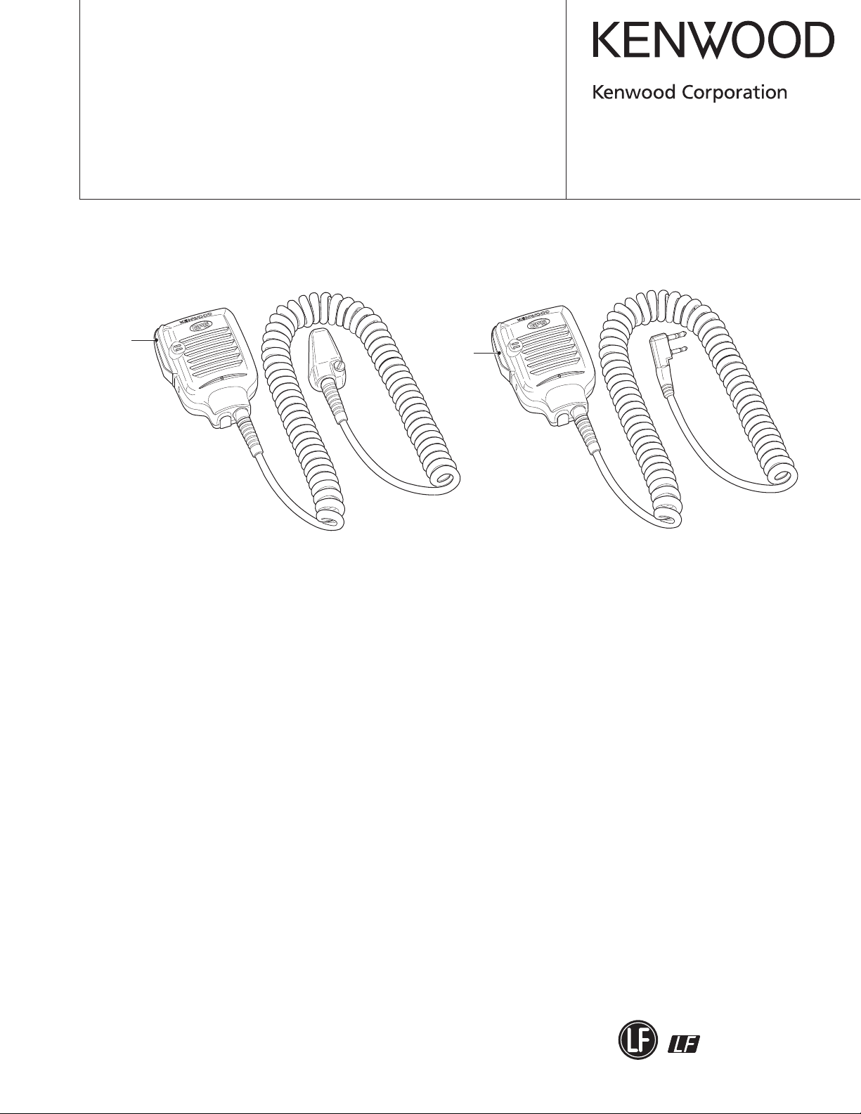
GPS SPEAKER MICROPHONE
Lever (PTT)
(D10-0629-08)
Lever (PTT)
(D10-0629-08)
KMC-47GPS/48GPS
SERVICE MANUAL
© 2010-8 PRINTED IN JAPAN
B51-8930-00 (Y) 550
KMC-47GPS
Document Copyrights
Copyright 2010 by Kenwood Corporation. All rights re-
served.
No part of this manual may be reproduced, translated,
distributed, or transmitted in any form or by any means, electronic, mechanical, photocopying, recording, or otherwise,
for any purpose without the prior written permission of Kenwood.
Disclaimer
While every precaution has been taken in the preparation of this manual, Kenwood assumes no responsibility
for errors or omissions. Neither is any liability assumed for
damages resulting from the use of the information contained
herein. Kenwood reserves the right to make changes to any
products herein at any time for improvement purposes.
KMC-48GPS
SPECIFICATIONS
General
Operating temperature range .....................–30°C~+60°C
(–22°F~+140°F)
Microphone
Impedance .................................................... 2.2k
Sensitivity ...................................... –45dB±5dB at 300Hz
Speaker
Impedance .........................................16Ω±15% at 1.2kHz
Rating input ............................................................. 0.8W
Maximum input .........................................................1.6W
Dimensions (W x H x D) ......................... 62 x 81 x 36 mm
(2.44 x 3.19 x 1.42 inches)
Weight ......................Approx. 230g/ 8.1oz.(KMC-47GPS)
230g/ 8.1oz.(KMC-48GPS)
GPS Receiver
Receiver system ...............................Parallel 12 channels
Receiver frequency
...........................
GPS data format .................. Compatible with NMEA 0183
GPS data update cycle ............................. Every 1 second
1575.42MHz±1MHz, L1 band, C/A code
Ω
(max)
This product complies with the RoHS directive for the European market.
This product uses Lead Free solder.
Page 2
KMC-47GPS/48GPS
Packing
Cover
GPS Unit
GPS Unit
Internal Battery
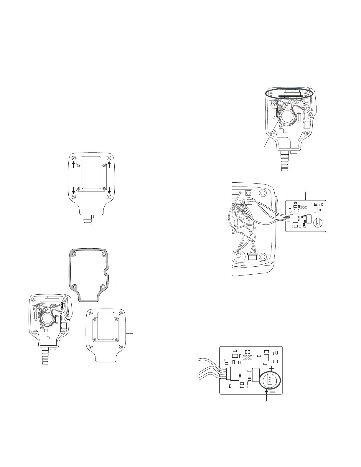
HOW TO REPLACE THE INTERNAL BATTERY
If a Cold Start occurs frequently (the transceiver cannot
star t GPS positioning after the transceiver is turned ON)
even though the transceiver has been continuously used, the
internal battery may be degraded. When the internal battery
terminal is less than 1.4V after charging, use the following
procedure to replace the internal battery.
CAUTION: THE OPERATOR MUST WEAR AN ANTISTATIC
BAND WHEN REPLACING THE BUILT-IN BATTERY IN ORDER TO PREVENT STATIC DISCHARGE. THE INSTALLED
IC MAY B E DAM AGED BY A DISC HARGE OF STATIC
ELECTRICITY.
1. Remove the KMC-47GPS/48GPS from the transceiver
and 4 screws on the rear panel.
3. Remove the GPS unit installed in the upper part of the microphone.
CAUTION: DO NOT DAMAGE CABLES WHEN REMOVING THE GPS UNIT.
2. Remove the cover and packing.
Note: Remove cables connected to the GPS unit, if needed.
4. Remove the internal battery in the GPS unit by using the
soldering iron. Replace the battery with a new battery.
CAUTION: BE SURE THE POLARITY OF THE BATTERY
BEFORE INSTALLING IT.
5. Reinstall the GPS unit, packing and cover.
2
Page 3

KMC-47GPS/48GPS
1
2
3
4
5
SP
AE
5M
MIC
PTT/RXD
CIRCUIT DESCRIPTION
The location data is calculated by the GPS unit and is
then sent to the transceiver via the RXD terminal of the connector (universal or 2-pin).
When the transceiver is turned OFF, the GPS unit enters
to backup mode and the power is supplied by the internal
rechargeable lithium battery.
When the transceiver is turned ON, the GPS unit enters
to normal operation mode and the power is supplied from
the transceiver via the 5M terminal of the connector (universal
or 2-pin). While the transceiver is turned ON, the internal rechargeable lithium battery charges.
It takes approximately 40 seconds to calculate the location
data when the GPS unit is “cold started” (full initialization).
GPS OPERATION CHECK METHOD AFTER REPAIRS
Check the GPS operation according to the following pro-
cedures.
1. Prepare the transceiver which incorporate the GPS function. (Set the GPS Position Display to a key, such as the
[S] key, with the FPU beforehand.)
2. Connect the KMC-47GPS/48GPS to the connector (universal or 2-pin) on the transceiver.
3. Turn the transceiver power ON.
4. Go outside, then press the [S] key (the key that you previously set as the GPS Position Display) on the transceiver.
5. The “GPS” and latitude information are displayed on the
LCD of a transceiver.
RESETTING THE GPS UNIT
When the KMC-47GPS/48GPS cannot determine the
position in a situation where GPS data is received, use the
following procedure to reset the GPS unit.
Reset the GPS unit by removing the internal battery and
then re-installing it. (To remove the internal battery, refer to
“HOW TO REPLACE THE INTERNAL BATTERY”.)
Note:
The KMC-47GPS/48GPS has an internal battery to back-
・
up the built-in pinpointing data. When the internal battery is
charged, the transceiver will retain the pinpointing data (the
last positional information) for approximately 20 days. (When
used for the first time, it takes approximately 10 hours to fully
charge the internal battery.)
When the internal battery is in the discharged state, pin-
・
pointing data returns to its initial value. When the positional
information is at its initial value while turning on the transceiver, the life cycle of the internal battery is considered.
Universal connector (KMC-47GPS)
Pin No. Name I/O Function
1 SSW O External speaker switch
2 SP+ I Speaker input (BTL + side)
3 SP- I Speaker input (BTL – side)
4 MSW O External MIC switch
5 EMC O MIC output
6 ME - MIC GND
7 PTT O PTT output
8 PF - No connection
9 NC - No connection
10 E - GND
11 5M I Input from the power with DC 5V
12 TXD - No connection
13 RXD O GPS data output
14 E - No connection
TERMINAL FUNCTION
2-pin connector (KMC-48GPS)
Pin No. Name I/O Function
1 SP I Input from AF AMP
2 AE - GND
3 5M I 5V DC input
4 MIC O Microphone output
5 PTT/RXD O PTT output/GPS data output
3
Page 4

KMC-47GPS/48GPS
C10
0.1µ
R15
10k
R17 1M
R19 10k
R18 10k
R21
10k
R12 10k
C18 0.1
µ
C9 220
µ
2
1
8
6
4
2
7
5
3
1
3
5
6
4
C19 0.1
µ
D3
IC2
R20 10
+
C17 10
µ
C16
0.1µ
BT1
+
NC_2
NC_1
BATT SD0
RD0
CN2
GPS MODULE
D1
R3
330
R16 10k
Q2
Q1
6 5 4
1 2 3
6 5 4
1 2 3
L1
L2
Vcc 5V
RXD
GPD (TXD)
E
TP4 RXD
TP3 GPD
TP2 E
TP1 VCC-5V
Checker
test point
C2 100p
D2
L3
5
4
3
2
1
CN1
GPS UNIT
IC2 : TK11233CMCL-G
Q1,2 : UM6K1NTN
D1 : RB501V-40TE-17
D2,3 : AVR-M1608C220KT2AB
L1~3 : MMZ1608Y601BT
IC1 : NJM3404AM
6
5
7
8
4
–
–
+
+
2.7k
R14
R3 1k
12k
L10
0
R12
C3 1000P
C4 1000P
R7
C17
10k
R8
10k
R9
47p
R2 1k
470p
SW1
PTT
470p
C5
10 µ
C9
10
µ
C1
10
µ
R13
R15
100
2.7k
R6
C7
22k
+
+
R5 68k
IC1
IC1
C6
10
µ
C8
10µ
10µ
R4
22k
R1
2.2k
3
2
1
P5
P6
P7
CN3
6
5
4
3
2
1
ECM
MAIN
ECM
SUB
PTT SWITCH UNIT
(W02-3755-08)
J1
EARPHONE JACK
Ø3.5
SP
P1
P2
MICROPHONE UNIT KMC-47GPS (W02-3755-08) KMC-48GPS(W02-3754-08)
SP+
SP–
MIC
MICE
PTT
GPD
E
Vcc 5V
1
2
3
4
5
6
7
8
1
2
3
4
5
6
7
8
1
2
3
4
5
6
7
8
1
2
3
4
5
6
7
8
(R17)
R16
0
1
2
3
4
5
6
7
8
9
10
11
12
13
14
15
17
SSW
SP+
SP–
MSW
EMC
ME
PTT
PF
NC
E
5M
TXD
RXD
E
SUB UNIT (W02-3755-08) KMC-47GPS
CN2
CORD CIRCUIT
MIC
MICE
VCC 5V
SP+
SP–
PTT
E
GPD
MIC
MICE
VCC 5V
SP+
SP–
PTT
E
GPD
UNIVERSAL
CONNECTOR
CN1
(P5)
(P7)
(P6)
(E)
(Vcc 5V)
(GPD (TXD))
CN2
CN1
VCC
TP6
R1
0
TP9
R14 10k
R20
R18
KMC-48GPS
2-pin CONNECTOR
KMC-47GPS
W02-3755-08
W02-3754-08
KMC-48GPS
NO
R20
0
MICROPHONE UNIT
MIC
MICE
VCC 5V
SP+
E
GPD
CORD CIRCUIT
1
2
3
4
5
SP
AE
5M
MIC
PTT/RXD
3
4
5
1
2
2
C20
100p
GPI0
SW1
PTT
PTT SWITCH UNIT
(W02-3754-08)
KMC-47GPS
KMC-48GPS
R22
0
KMC-47GPS
KMC-48GPS
0
R18
5.6
C21 47p
=
=
=
=
=
=
=
SCHEMATIC DIAGRAM
4
Page 5

KMC-47GPS/48GPS
11
18
3
5
36x4
28
35x4
22
37x3
21
38
40x2
4
24
39
20
33
34
41
MICROPHONE
UNIT
SUB UNIT
41
PTT SWITCH UNIT
701
704
703
702x2
707
700
705
2
1
KMC-48GPS
12
KMC-47GPS
706 GPS UNIT
43
=
=
(48GPS ONLY)
41
720
719
713
709
712
711
710
708
714
715
716
717
718
721
EXPLODED VIEW
1: In order to maintain the waterproofing performance, the cord ASSY with plug cannot be replaced.
✽
2: The GPS unit cannot be replaced.
✽
Parts with the exploded numbers larger than 700 are not supplied.
5
Page 6

KMC-47GPS/48GPS
PARTS LIST
KMC-47GPS/48GPS
Ref. No.
3 A02-3988-08 PLASTIC CABINET ASSY (REAR)
4 B09-0382-08 CAP (PHONE)
5 B42-7733-04 STICKER (WEEE)
11 D10-0629-08 LEVER (PTT)
12 F07-1932-02 COVER KMC-47GPS
18 G13-1638-08 CUSHION (PTT LEVER)
20 G13-2201-08 CUSHION (SPEAKER)
21 G13-2202-08 CUSHION (MAIN ECM)
22 G53-0820-08 PACKING (CASE)
24 G53-0834-08 PACKING (SPEAKER)
28 J29-0644-08 CLIP ASSY
33 K29-5217-18 KEY TOP (PTT)
Address
New parts
Parts No.
KMC-47GPS/48GPS
Description
Destination
34 N08-0565-08 DRESSED SCREW
35 N09-6542-08 TAPTITE SCREW (CASE)
36 N46-2605-60 PAN HEAD TAPPING SCREW (CLIP)
37 N80-2005-43 PAN HEAD TAPTITE SCREW (PCB)
38 S70-0471-08 TACT SWITCH
39 T07-0359-18 SPEAKER
40 T91-0584-08 MIC ELEMENT
41
41
43
2967-3, Ishikawa-machi, Hachioji-shi, Tokyo, 192-8525 Japan
P.O. BOX 22745, 2201 East Dominguez Street, Long Beach,
CA 90801-5745, U.S.A.
6070 Kestrel Road, Mississauga, Ontario, Canada L5T 1S8
Rembrücker Str. 15, 63150 Heusenstamm, Germany
Leuvensesteenweg 248 J, 1800 Vilvoorde, Belgium
W02-3754-08 ELECTRIC CIRCUIT MODULE (MIC, PTT SW
✽
W02-3755-08 ELECTRIC CIRCUIT MODULE (MIC, PTT SW, SUB UNIT) KMC-47GPS
✽
W09-1072-08 LITHIUM CELL
✽
Amsterdamseweg 37, 1422 AC Uithoorn, The Netherlands
Via G. Sirtori, 7/9 20129 Milano, Italy
Bolivia, 239-08020 Barcelona, Spain
Talavera Business Park Building A, 4 Talavera Road,
North Ryde NSW 2113 Australia
KMC-47GPS
UNIT) KMC-48GPS
L’ Etoile Paris Nord 2, 50 Allée des Impressionnistes,
Bp 58416 Villepinte, 95944 Roissy Ch De Gaulle Cedex
KENWOOD House, Dwight Road, Watford, Herts.,
WD18 9EB United Kingdom
Suite 2504, 25/F, Tower 2, Nina Tower, No. 8 Yeung Uk Road,
Tsuen Wan, New Territories, Hong Kong
1 Ang Mo Kio Street 63, Singapore 569110
 Loading...