

Kenwood KDV-MP735 Service Manual
DVD RECEIVER
KDV-MP735
SERVICE MANUAL
© 2004-3 PRINTED IN JAPAN
B53-0158-00 (N) 428
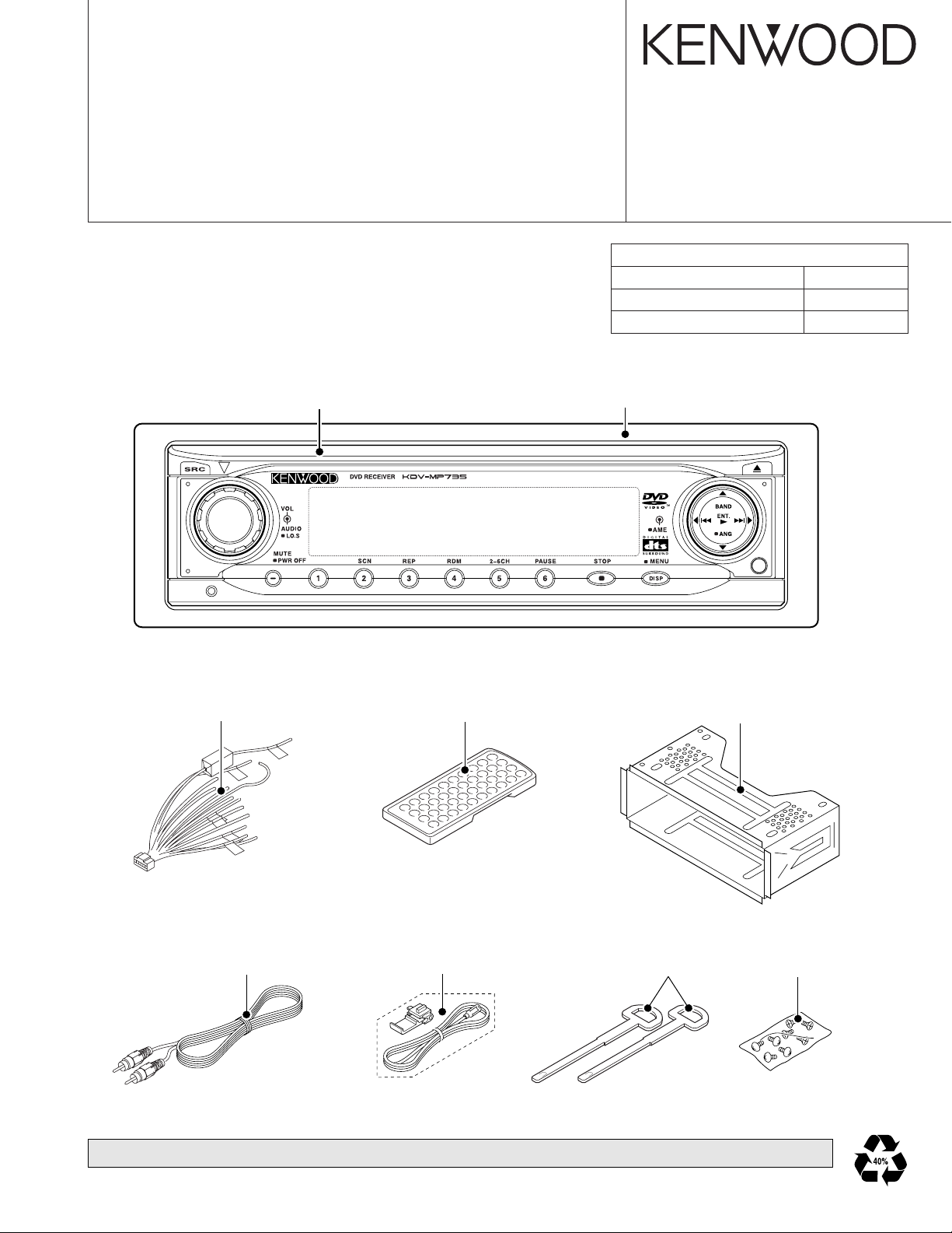
DVD MECHANISM EXTENSION CORD
Flat cable 30cm (40P) E39-0677-08
Wire harness 30cm (4P) E39-0678-08
Wire harness 30cm (6P) E39-0679-08
DC cord
(E30-6383-08)
Panel assy
(A64-3398-08)
Escutcheon
(B07-3119-08)
Remote controller assy (RC-DV450)
(A70-2065-08)
Mounting hardware
(J22-0236-08)
Cord with plug
(E30-6367-08)
(3m)
DVD mechanism’s ASSY internal parts are not supplied. Please exchange the DVD mechanism ASSY (D40-1197-08).
Connecting cord assy
(E30-6373-08)
(1m)
Lever
(D10-4851-08)
Screw set
(N99-1723-05)
2
SDRAM FLASH E2PROM
D/AMPEG
DVD
VIDEO SW
TUNER
AUX IN
ASP
MECH
SERVO
V2
V1
VOL
6CH
LPF
POWER
AMP
LEVEL
INVERT
DRIVER
MOTOR
LOAD
4094
MCU
DVD MECHA
LOAD MOTOR
DRIVER
SET UP
DIODE
LCD
DRIVER
KEY PAD
LINE
AMP
OUT
OUT
F/P
U501 U603
U704
U604 703
U302
LCD901
U902
U203
U202
U204
U601
U701-
U705
U301
U101
S5VD12V
D3.3V D5V
A5V
D3.3V
P9VP5V P9V
D3.3V
P9V
P9V A9V
BU
D14V
P5VD14V
VDD5V
P5V
VLCD8V V5V
1.8V
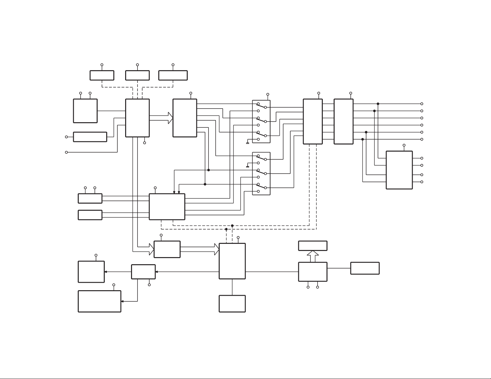
KDV-MP735
BLOCK DIAGRAM
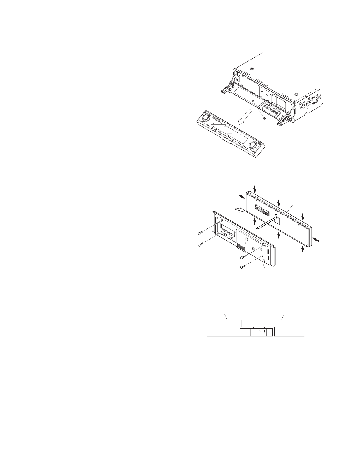
DISASSEMBLY FOR REPAIR
A
B
F
B
B
B
FRONT PANEL (C)
REAR PANEL (D)
1) Remove a screw (A).
2) Remove the panel section by sliding it downward.
3) Remove four screws (B).
4) Separate the rear panel by applying force in the inside edge
(D).
KDV-MP7 35
The front panel (C) and the rear panel (D) are fixed on 6 points
as indicated by the arrows in the figure.
It is easy to separate front and rear panels by starting from the
(F) section.
REAR PANEL (D) FRONT PANEL (C)
3
 Loading...