

Kenwood KD-CW-40-AY, KD-CW-3534-AG Service Manual
CD RECEIVER
KDC-W3534A/G
KDC-W40AY
SERVICE MANUAL
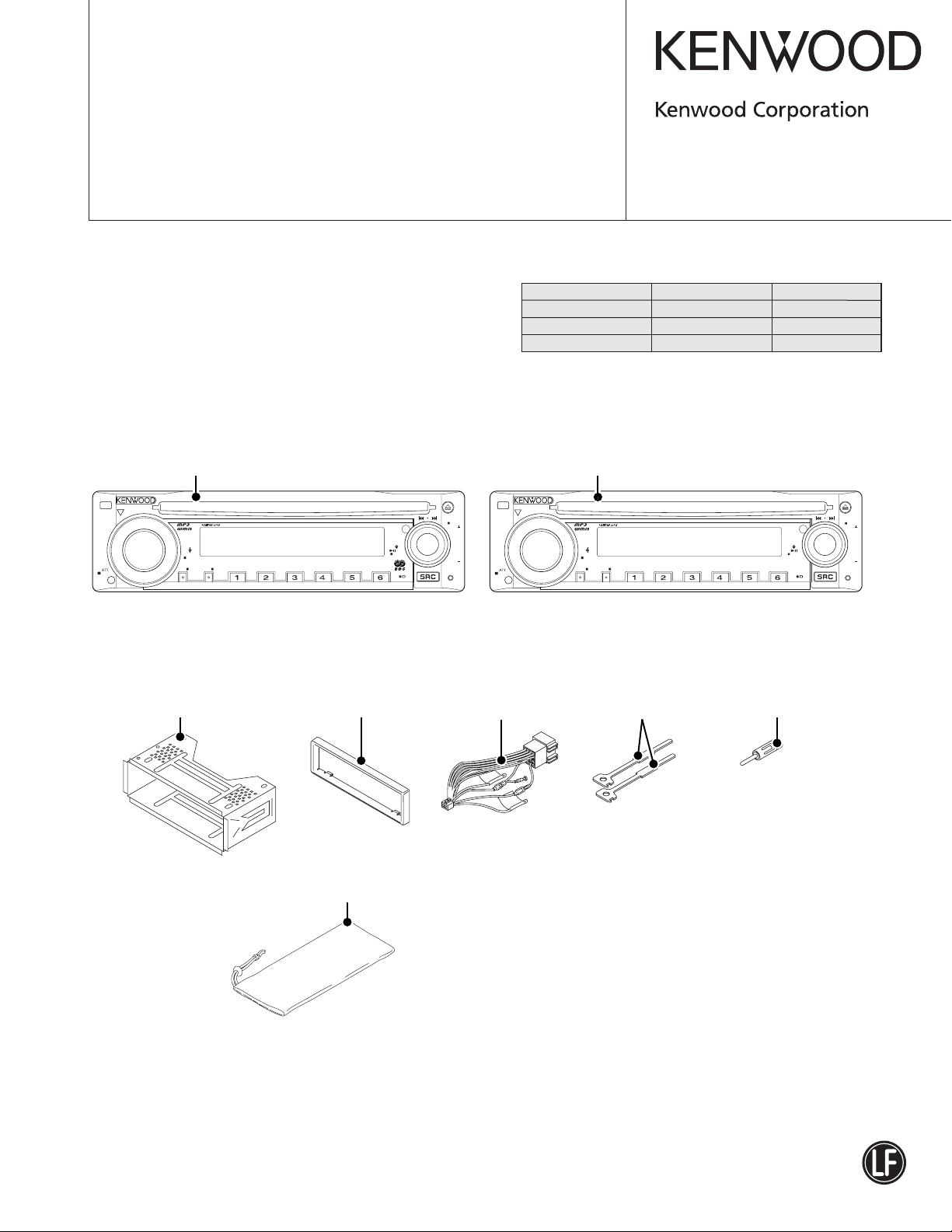
SPARE TDF PANEL
MAIN UNIT NAME TDF PARTS No. TDF NAME
KDC-W3534A Y33-2420-64 TDF-W4034Y
KDC-W3534G Y33-2420-64 TDF-W4034Y
KDC-W40AY Y33-2420-66 TDF-W434Y
© 2006-5 PRINTED IN JAPAN
B53-0422-00 (N) 350
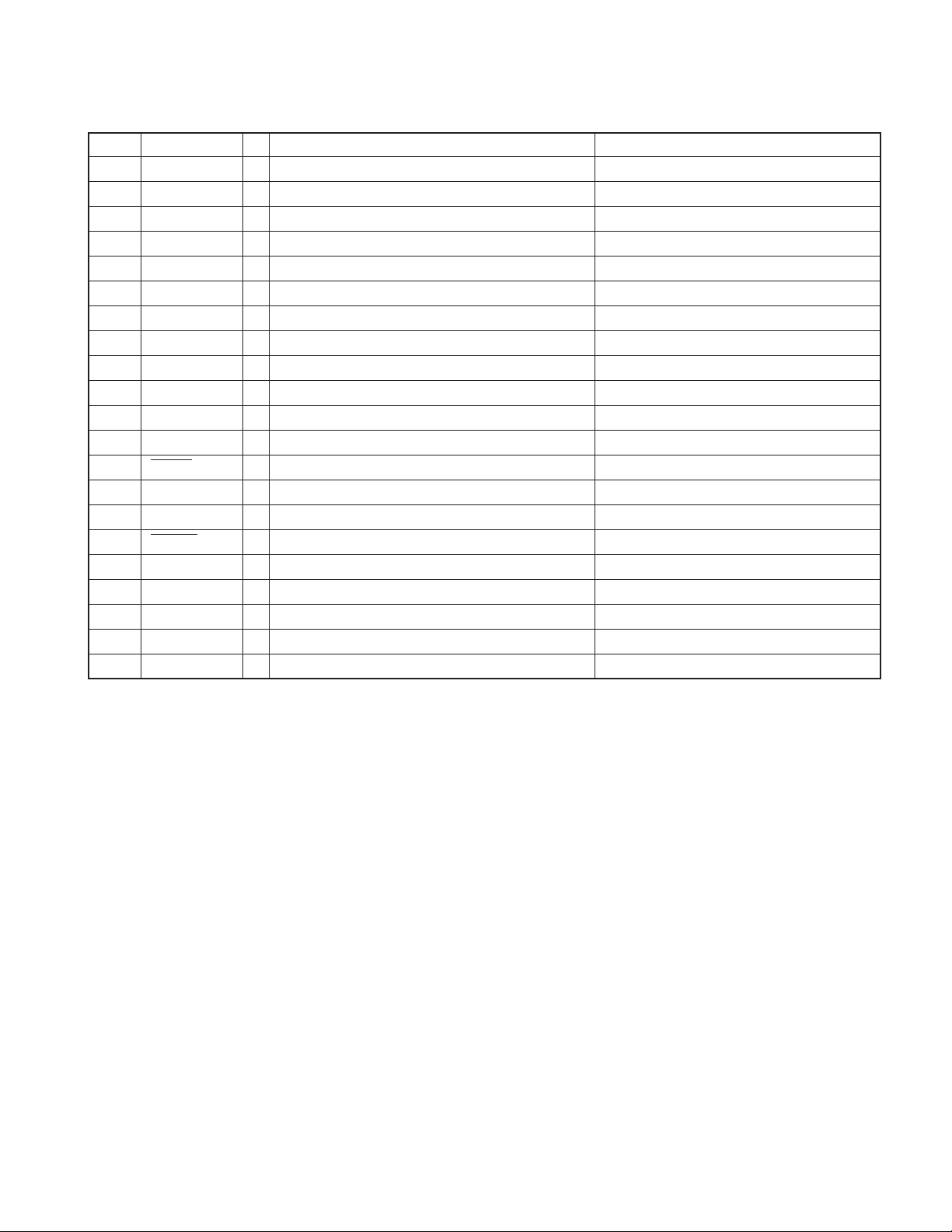
Panel assy
KDC-W3534A/G (A64-3957-12)
VOL
AUD
SET UP
TI Q
DIM
AME MENU
Mounting hardware assy
(J21-9716-03)
SCAN RDM REP
Escutcheon
(B07-3122-01)
Carrying case
(W01-1661-05)
F.SEL
KDC-W3534
Panel assy
KDC-W40AY (A64-3806-22)
SCRL
FM
/
PTY
DISP
AM
FF
DIM
DC cord
(E30-6427-05)
VOL
AUD
SET UP
AUTO Q
AME MENU
Lever
(D10-4589-04) x2
SCAN RDM REP
KDC-W40
DISP
F.SEL
Antenna adaptor
(T90-0523-05)
SCRL
FM
AM
FF
European market products comply with the
RoHS
directive.
This product uses Lead Free solder.
KDC-W3534A/W3534G
KDC-W40AY
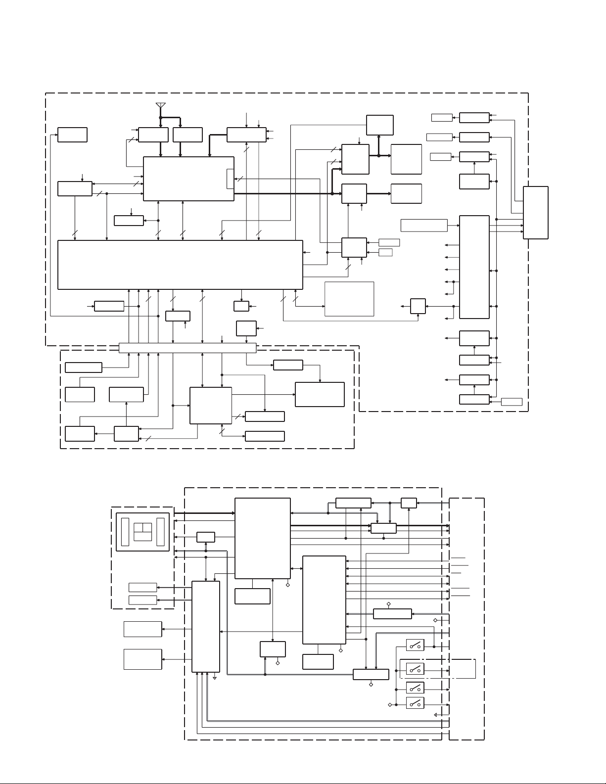
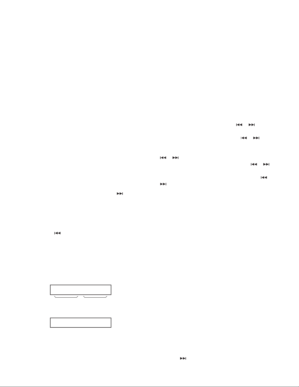
ELECTRIC UNIT (X34- )
J2
ANT
CN3
WIRED
REMOTE
AM+B
1
Q501
AM AGC
IC10
IC7
RDS
DECODER
SW5
A8V
1
IC11
2
SW5
TUNER + MPX + E-VOL.
E2PROM
32211
IC1
BU5
IC8
RESET IC
2
CN
(X16- )
GND
PANEL DET
S1
RESET
S11
ROT ARY
ENCODER
SW5
IC3
REMOTE
SW5
Q21
SW5V
PAN5
1
Q502
FM AGC
3
SYSTEM u-COM
Q401
PAN5V
BU5
5
IC1
VFD DRIVER
BLOCK DIAGRAM
SERVO+B
A8V
DME1
1
Q301
ILLUMI+B
9
CD MECHA
1
MUTE
R11-15
1/2W
Rx5
2
BU5DSI
FL+B
J5
J1
LED
KEY ILLUMI
SWITCH
KEY MATRIX
D5V
BU
IC14
3
1
Q701-703
BU5
DC-CN etc
FL+B
PHONE
ACC-DET/BU-DET
P.ON FL
PS1-1/PS1-2/PS1-3
PS2-1/PS2-2
119
R80-82
1/2W Rx3
ED1
DISPLAY
BU
POWER
IC
PRE
MUTE
BU5
Q104,105
MUTE
1
BU5
Q901-903
DC
OFFSET
DET
From
Q103
BU DET
RST
From
X16-
J1
J6
FM+B
SP-OUT
FRONT L/R
REAR L/R
PRE-OUT
FRONT
REAR
To IC1
PHONE
To IC1
ACC DET
To IC1
BU DET
From IC1
PS1-1/PS1-2/PS1-3
PS2-1/PS2-2
FL+B
AM+B
SW5
BU5
Q8,9
FM
+B
A8V
SERVO+B
R103
PHONE
BU5
Q101
ACC-DET
Q103
BU-DET
BU5
Q51
SURGEDET
IC3
POWER
SUPPLY
IC
J1
DC-CN
PHONE
ACC
B.U.
P-ANT
P-CON
D5
Q2,3
CD
SERVO
Q1
SW14V
SW5
Q6,7
ILLUMI+BILLUMI+B
Q5
SW14V
From IC1
PON FL
MOTHER
BOARD
(X14- )
A8V
L-ch
R-ch
A.GND
D.OUT
MRST
MSTOP
CLK
DATA
MUTE L
MUTE R
BU5V
D.GND
D5.0V
S3
LOE/LIM-SW
S4
8EJE-SW
S2
12EJE-SW
S1
LOS-SW
S.GND
S7.5V
LO/EJ
MOTOR
DPU1
A
E
C
FO COIL
TR COIL
DM1
SPINDLE
MOTOR
DM2
LOADING &
SLED
MOTOR
CD PLAYER UNIT (X32-5920-04)
IC7
RF AMP
+
SERVO
PROCESSOR
B
F
Q4
APC
IC3
MOTOR
DRIVER
+
MP3 DECODER
+
WMA DECODER
+
AAC DECODER
+
1Mbit SRAM
VREF
X2
CLOCK
16.934MHz
D.GND
DMUTE
IC4
MICRO
PROCESSOR
IC8
S.GND
SDRAM
16MBIT
D.GND
X1
16.00MHz
CLOCK
IC1
A3.3V REG
P-ON2
P-ON1
D.GND
IC6
IC2
IC5
BU3.3V REG
D3.3V REG
D.GND
D.GND
Q7,8
SW
LPF
D.GND
D.GND
(0-01)ONLY
S.GND
2
KDC-W3534A/W3534G
KDC-W40AY
COMPONENTS DESCRIPTION
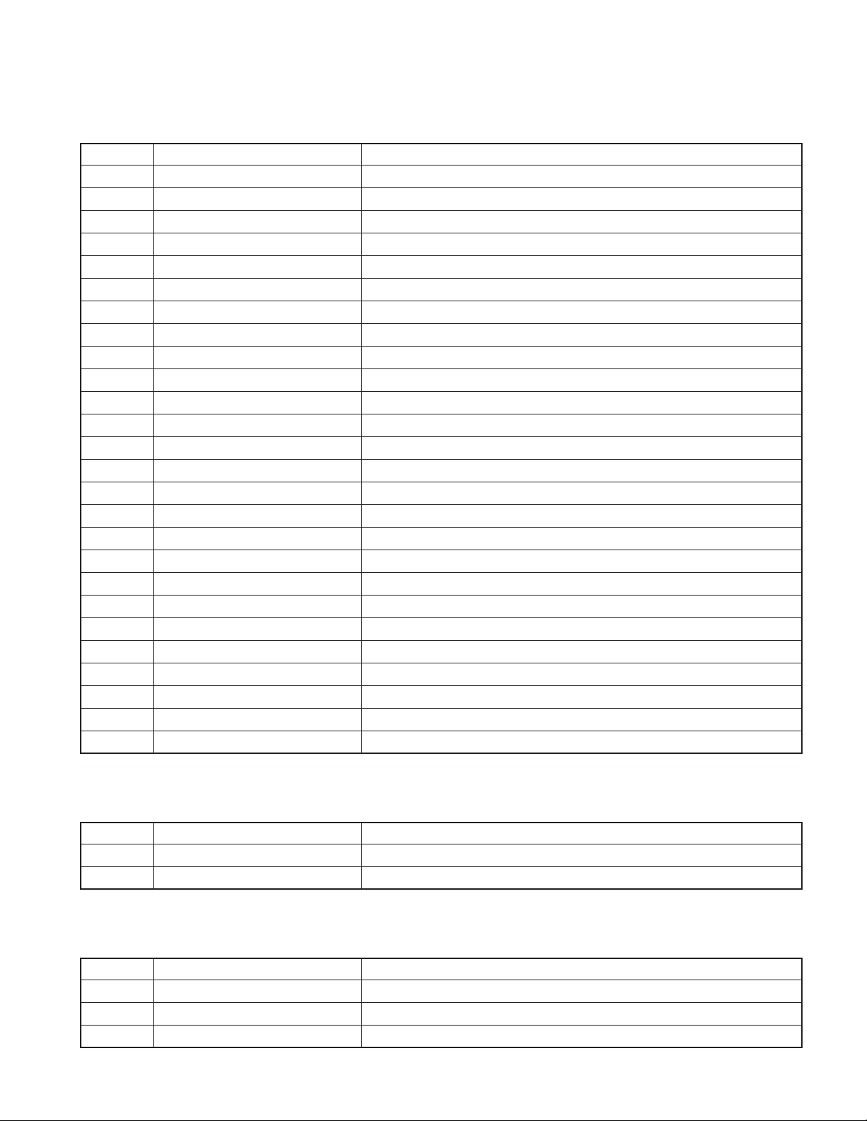
● ELECTRIC UNIT (X34-433x-xx)
Ref. No. Application / Function Operation / Condition
IC1 System µ-COM System control
IC3 Power Supply IC DC5V x 1, 7.9V x 1, 8.1V x 2, 10.2V x 1, P-CON, P-ANT output
IC7 RDS Decoder RDS decoder
IC8 Reset IC “L”: detection voltage below 3.6V
IC10 E-VOL & Tuner E-VOL, Tuner, Stereo decoder
IC11 E2PROM Save & Load for tuner adjust data
IC14 Power IC Signal amplifier
Q1 14V SW ON when the base goes “Hi”
Q2 SERVO+B AVR Output voltage 7.5V
Q3 Control SW for SERVO+B ON when the base goes “Hi”
Q5 FL+B SW ON when the base goes “Hi”
Q6 FL+B AVR Output voltage 11V
Q7 Control SW for FL+B ON when the base goes “Hi”
Q8 FM+B AVR Output voltage 8.0V
Q9 Control SW for FM+B ON when the base goes “Hi”
Q51 SERGE Det. ON when the base goes “Hi”
Q101 ACC Det. ON when the base goes “Hi” during ACC is applied
Q103 BU Det. ON when the base goes “Hi” during BU is applied
Q104,105 MUTE Control ON when the base goes “Hi”
Q401 Panel 5V SW ON when the base goes “Lo”
Q501 AM RF Amplifier Adjusts for gain
Q502 FM RF Amplifier RF amplifier
Q503 AFS Control AFS time controller
Q802 Buffer IC10 QUAL output buffer
Q901 DC OFFSET Det ON when the base goes “Q902 and Q903’s output separate”
Q902,903 DC OFFSET Det SW ON when the base goes “IC14’s SP-OUT (DC) separate”
● SWITCH UNIT (X16-350x-xx)
Ref. No. Application / Function Operation / Condition
IC1 VFD DRIVER
Q21 PAN SW5V “ON” when the base goes “H”
● CD PLAYER UNIT (X32-5920-04)
Ref. No. Application / Function Operation / Condition
IC1 A3.3V regulator Power supply for audio 3.3V
IC2 Low pass filter
IC3 4ch BTL driver Driving spindle motor and loading/ejection operation
3
KDC-W3534A/W3534G
KDC-W40AY
COMPONENTS DESCRIPTION
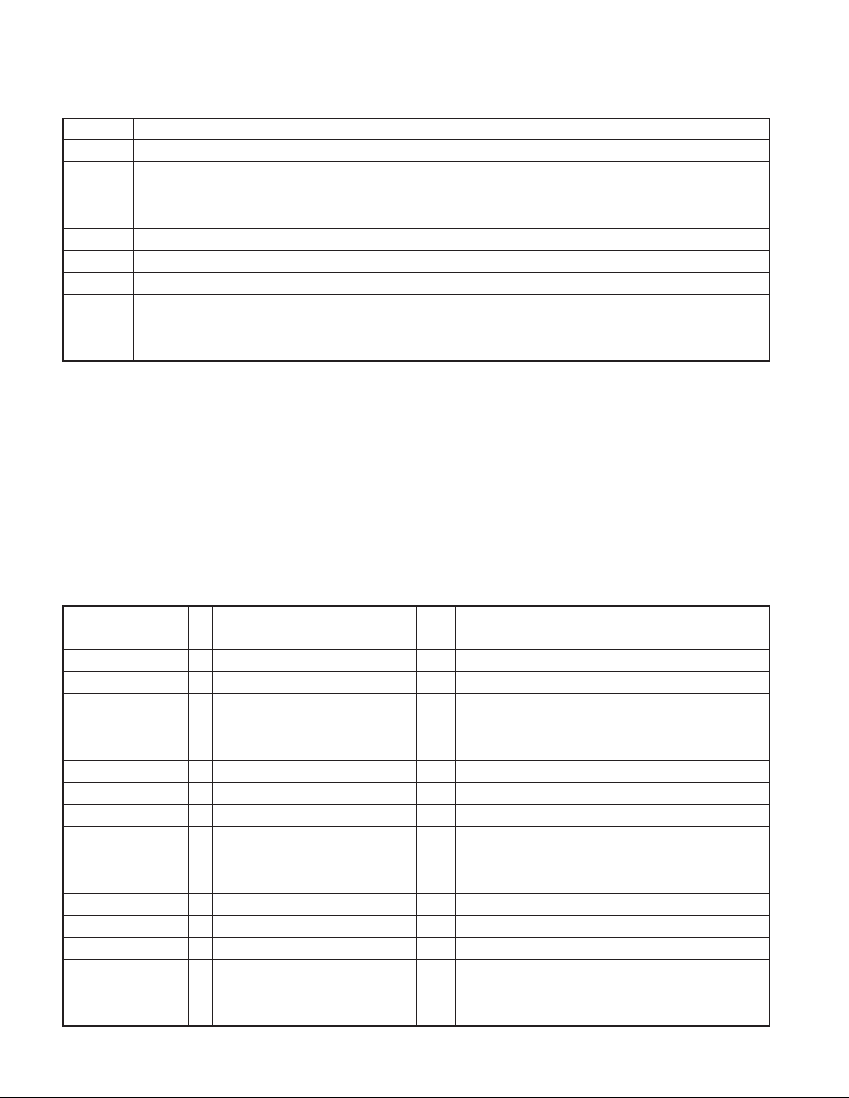
Ref. No. Application / Function Operation / Condition
IC4 Mechanism µ-com
IC5 BU3.3V regulator Power supply for backup 3.3V
IC6 D3.3V regulator Digital 3.3V power supply
IC7 Audio DAC built-in servo DSP MP3, WMA, and AAC compatible
IC11 Buffer IC Level shift
Q1 A3.3V discharge circuit
Q4 APC (Auto power control) Adjusts current to be sent to laser
Q5,6 SW 5V
Q7,8 SW 8V
D1 APC (Auto power control) Protects the pick-up laser diode
MICROCOMPUTER’S TERMINAL DESCRIPTION
● SYSTEM µ-com: IC1 (X34-: ELECTRIC UNIT)
Pin No. Pin Name I/O Application
1 PS2 2 O Power IC control 2-2 q Refer to the truth value table
2 PS2 1 O Power IC control 2-1 q Refer to the truth value table
3 PS1 1 O Power IC control 1-1 q Refer to the truth value table
4 PS1 2 O Power IC control 1-2 q Refer to the truth value table
5 PS1 3 O Power IC control 1-3 q Refer to the truth value table
6 REMO I Remote control signal input Detect pulse width
7NC-Not used Fix to output L
8 BYTE I Memory extension bus width setting Connect to VSS
9 CNVSS - Connect to VSS. H: Can be changed (Only for FLASH)
10 XCIN - 32.768kHz
11 XCOUT - 32.768kHz
12 RESET - L: RESET
13 XOUT - 10.0MHz
14 VSS 15 XIN - 10.0MHz
16 VCC1 17 NMI I Connect to VCC (pull up)
Truth Value
Table
Processing / Operation / Description
4
KDC-W3534A/W3534G
KDC-W40AY
MICROCOMPUTER’S TERMINAL DESCRIPTION
Pin No. Pin Name I/O Application
18 CN DET I Panel communication detection H: Without PANEL, L: With PANEL
19 NC - Not used Fix to output L
20 KEY REQ I
21 PON FL O Key illumi power supply control ON: H, OFF: L
22 DSI I/O DSI control OFF: Hi-z PANEL detached, Pulse drive ON: H
23 PON PANEL I/O Panel 5V control
24~27 NC - Not used Fix to output L
28 PWIC BEEP O Beep output
29 CD SCL I/O CD mechanism I2C clock output
30 CD SDA I/O CD mechanism I2C data input/output
31
32
33 VFD CL O VFD clock output 52kHz
34 VFD INH O VFD data blanking output
35 AUD SDA I/O IC10 I2C data input/output
36 AUD SCL I/O IC10 I2C clock input/output
37 CD MUTE I CD MUTE request L: MUTE request
38 CD MSTOP O CD mechanism µ-com stop
39
40 CD LOEJ I/O CD motor control w Refer to the truth value table
41 EPM I FLASH EPM input
42 CD MOTOR O CD motor control w Refer to the truth value table
43
44 CD MRST O CD mechanism µ-com RST H: Normal, L: Reset
45
46 VFD CE O VFD control request
47 CD LOS SW I CD loading detection
48,49 NC - Not used Fix to output L
50
51 NC - Not used Fix to output L
52
53~56 NC - Not used Fix to output L
57 RDS AFS L O TUN RDS MUTE output
58 TUN ADJ I
59 TUN SD I TUN search stop input H: Station found, L: Station not found
VFD SYS DATA
VFD PAN DATA
CD LOE LIM SW
CD DISC8 SW
CD DISC12 SW
ROTARY CW
ROTARY CCW
Communication request form VFD driver
O VFD data output Data output
I VFDINT/data input INT/data input
I CD detection (chucking SW) H: Loading completed, L: Disc not found
I CD disc detection (8cm)
I CD disc detection (12cm)
IVOL key input Detect pulse width
IVOL key input Detect pulse width
For IC10 adjustment + When ADJ=H, PS1-1,2,3=Hi-z, PS2-1,2=Hi-z,
E2PROM write request TUN DATA, CLK=Hi-z, MUTE=L, E2PROM writing-in
Truth Value
Table
Processing / Operation / Description
Connect to INT
ON: L, Momentary power down, when PANEL detached,
11 minutes after ACC OFF: Hi-z
H: Cancel reset, L: RESET, L: Momentary power down,
when PANEL detached, 11 minutes after ACC OFF
H: Mechanism µ-com in operation, L: Mechanism µ-com stopped
L: Can be changed (Only for FLASH). Connect to VSS (pull down)
H: Normal
L: FM/AM SEEK, AF search (L: When Tuner SRC Auto Zero)
5
KDC-W3534A/W3534G
KDC-W40AY
MICROCOMPUTER’S TERMINAL DESCRIPTION
Pin No. Pin Name I/O Application
60
61 PON FM I/O FM power supply control H: When FM is active, Hi-z: When FM is not active
62 VCC2 63 NC - Not used Fix to output L
64 VSS 65 MUTE I/O MUTE L: MUTE OFF, Hi-z: MUTE ON
66 PWIC SVR O SVR discharge circuit (Not used)
67 PWIC STBY O Power IC stand-by control POWER ON: H, POWER OFF: L
68 PWIC MUTE O Power IC MUTE
69~74 NC - Not used Fix to output L
75 RDS CLK I
76 TUN TYPE1 I Destination setting 1 e Refer to the truth value table
77 TUN TYPE2 I Destination setting 2 e Refer to the truth value table
78 TYPE1 I Destination change r Refer to the truth value table
79 TYPE2 I Destination change r Refer to the truth value table
80 TYPE3 I Destination change r Refer to the truth value table
81 RDS NOISE I FM noise detection
82
83
84~86 NC - Not used Fix to output L
87
88 LINE MUTE I Line mute detection
89,90 NC - Not used Fix to output L
91 RDS DATA I RDS decoder DATA input
92 RDS QUAL I RDS decoder QUAL input
93 NC - Not used Fix to output L
94 ACC DET I ACC power supply detection L: ACC ON, H: ACC OFF
95 BU DET I Momentary power down detection
96 AVSS - Connect to VSS
97 REF CON O VREF control Connect to VREF
98 VREF - Connect to REF CON
99 AVCC - Connect to VCC
100 NC - Not used Fix to output L
TUN FANC OUT
TUN SMETER
RDS AFS L 2
PWIC DC DET
O TUNER block (in µ-com) check Only when test mode, E2P OK: H, E2P NG: L, Normal: L
RDS decoder CLK input (RDS model only)
IS meter input
TUN RDS MUTE output
O
(Not used in circuit, used in software)
I DC offset detection
Truth Value
Table
Processing / Operation / Description
When momentary power down by POWER OFF,
5 seconds : H, Thereafter: L
While STANDBY source,
Momentary power down: L , While TEL MUTE: L
H: Normal
L: FM/AM SEEK, AF search (L: When Tuner SRC Auto Zero)
* Same process with RDS AFS L
TEL MUTE: 1V or lower, NAVI MUTE: 2.5V or higher
NAVI MUTE: 1V or lower and 2.5V or higher (J-TYPE)
L: BU found, H: BU not found, momentary power down
Activated within 4ms after detection of momentary power down
6
MICROCOMPUTER’S TERMINAL DESCRIPTION
Truth Value T able
q : Power supply IC (IC3) control
SEL1 (Pin No. 11)
PS1-2 PS1-3 PS2-1 ILLUMI P-CON P-ANT
LLLOFF OFF OFF
LLHONOFF OFF
HLHONONOFF
HHHONONON
SEL2 (Pin No. 12)
PS1-1 PS2-2 AUDIO SW5 AM
LLOFF OFF OFF
HLONON OFF
HHONON ON
KDC-W3534A/W3534G
KDC-W40AY
w : CD mechanism control operation
CD MOTOR CD LOEJ
Stop L L
Load H L
Eject H H
Brake H Hi-z
e : Destination setting
Model
KENWOOD brand model (initial value) L L
OEM model (with CRSC changed) L H
KENWOOD brand model (with CRSC changed) H L
KENWOOD brand model (to support test-driving in EU)
TYPE 1 TYPE 2
HH
r : Destination change
TYPE 3 TYPE 2 TYPE 1
(Pin 80) (Pin 79) (Pin 78)
000KKDC-MP202
001JE313S
010EKDC-3034A/3034AY/W4034A/W4034AY/W410A/W410AY/W3534A
011EKDC-W434A/W40AY
100KKDC-MP2032CR
101MKDC-MP333/MP333RC/MP433
110EKDC-3034G/3034GY/W4034G/W4034GY/W410G/W410GY/W3534G
111J/E E212/E212S/KDC-W40GY/W434G/W434GY
Destination
Model
● MECHANISM µ-com : IC4 (X32- : CD PLAYER UNIT)
Pin No. Pin Name I/O Application Processing Operation Description
1NC-Not used Low-fixed
2 E2P SCL I/O ROM correction E2P I2C clock
3~5 NC - Not used Low-fixed
6 VDD - 5V electric potential
7 GND - GND electric potential
8,9 NC - Not used Low-fixed
10,11 PON1, PON2 O Power ON/OFF control H : ON, L : OFF
12 LOE/LIM SW I Down-limit SW detection L : Inner circumference detection
13 DAC MUTE O DAC MUTE control L : MUTE OFF
7
KDC-W3534A/W3534G
KDC-W40AY
MICROCOMPUTER’S TERMINAL DESCRIPTION
Pin No. Pin Name I/O Application Processing Operation Description
14 DAC RST O DAC RESET L : RESET
15 EMPH O External DAC Emphasis control L : Emphasis OFF
16,17 NC - Not used Low-fixed
18 IC/Vpp - Write voltage (FLASH) H : In writing
19 MUTE L O Lch audio MUTE control L : MUTE ON, H : MUTE OFF
20 MUTE R O Rch audio MUTE control L : MUTE ON, H : MUTE OFF
21 TYPE I DAC switching L : DSP built-in DAC Not used
22 TEST O 1 O TEST MODE O 1 (Not used)
23 TEST O 2 O TEST MODE O 2 (Not used)
24 TEST O 3 O TEST MODE O 3 (Not used)
25 TEST O 4 O TEST MODE O 4 (Not used)
26 NC - Not used Low-fixed
27 WAIT I Wait control signal detection
28~30 NC - Not used Low-fixed
31 RESET I Reset detection H : NORMAL, L : RESET
32 XT1 I Not used
33 XT2 - Not used
34 REGC 35 X2 36 X1 I
37 Vss - GND electric potential
38 VDD - 5V electric potential
39 NC - NC
40 WRL I Multiplex WRITE signal
41,42 NC - Not used Low-fixed
43 RD O Multiplex RD signal
44 ASTB O Multiplex ASTB signal
45 NC - Not used Low-fixed
46 NC - Not used Low-fixed
47~54 AD0~AD7 I/O Multiplex address/data
55 BVdd - BUS interface power supply
56 BVss - BUS interface GND
57~61 AB8~AB12 I/O Multiplex data/address
62~65 NC - Not used Low-fixed
66 CS O Chip select control H : OFF, L : ON
67 DSP RESET O DSP reset control H : NORMAL, L : RESET
68~70 NC - Not used Low-fixed
71 Avdd 72 Avss 73 Avref I A/D port reference voltage input
8
KDC-W3534A/W3534G
KDC-W40AY
MICROCOMPUTER’S TERMINAL DESCRIPTION
Pin No. Pin Name I/O Application Processing Operation Description
74 RAMSEL2 I With DRAM/No DRAM switching for different models H : With DRAM, L : No DRAM
75 RAMSEL I With DRAM/No DRAM switching for different models H : With DRAM, L : No DRAM
76 RZM I 0bit MUTE detection H : ≥1.7V, L : <1.7V
77 LZM I 0bit MUTE detection H : ≥1.7V, L : <1.7V
78 AAC I AAC compatibility switching H : AAC non-compatible, L : AAC compatible
79 ASEL I Audio output polarity switching H : Reverse output, L : Non-reverse output
80 E2P WR I E2PROM write switching H : E2PROM WRITE, L : NORMAL
81 TEST I 0 I TEST MODE I 0 (Not used)
82 TEST I 1 I TEST MODE I 1 (Not used)
83 TEST I 2 I TEST MODE I 2 (Not used)
84 TEST I 3 I TEST MODE I 3 (Not used)
85,86 NC - Not used Low-fixed
87 MSTOP I Standby restart interruption H : STOP release, L : STOP
88 INTSV I Interruption from servo IC H : Interruption
89~92 NC - Not used Low-fixed
93 D-MUTE O Driver MUTE H : OFF, L : ON
94 SYS SDA I/O System µ-com I2C data
95 NC - Not used Low-fixed
96 SYS SCL I/O System µ-com I2C clock
97~99 NC - Not used Low-fixed
100 E2P SDA I/O ROM correction E2P I2C data
9
KDC-W3534A/W3534G
KDC-W40AY
TEST MODE
● How to enter the test mode
Press and hold the [1] and [3] keys and reset.
● How to clear the test mode
Reset, momentary power down, Acc OFF, Po wer OFF, detach the panel.
● Test mode default condition
• Source is STANDBY.
• Display lights are all turned on.
• The volume is at -10dB (The display is 30).
• LOUD is OFF.
• CRSC is off regardless of the availability of switching function.
• SYSTEM Q (dB equalizer) is NATURAL (=FLAT).
• BEEP should always functions when the key is pressed.
● Specification of test mode for tuner
• TUNER mode [4] key frequency shall be 98.3MHz.
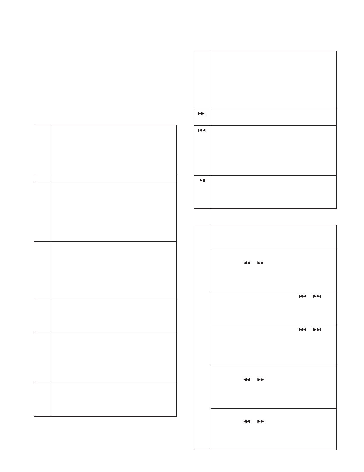
● CD receiver test mode specification
• Display mode default setting shall be P-TIME.
• Jumps to the following tracks by pressing the [
No. 9 → No. 15 → No. 10 → No. 11 → No. 12 → No. 13 →
No. 22 → No. 14 → No. 9 (recursive)
Note that when playing an MP3 / WMA / AAC disc with 8
files or less, the disc is played from the 1st track in the
normal order.
• Pressing the [ ] key goes back by 1 track from the track
being played.
• While in CD source, press the [1] key to jump to No. 28.
• While in CD source, press the [2] key to jump to No. 14.
• While in CD source, press the [3] key to display the CD
mechanism model name and the version. Press the [3] key
again to go back to the normal screen. (Time code display)
MP3 CD mechanism
6680:0123
Model name
Normal CD mechanism
Version
NORM:CD
• When CD is the source, press the [6] key to jump to No. 15.
At this time, the volume value is set to 25.
10
]key.
● AUDIO adjust mode
• Press the [AUD] k e y and enter the audio adjustment mode.
• Press the remote controller [∗] key and [AUD] k e y to go into
the audio adjustment mode.
• Both AUDIO FUNCTION MODE and SETUP MODE adjustment items are included.
•By pressing [AUD] key and then [FM] key, switch the item
to be adjusted in the following order.
The default item shall be Fader, and then the item is forwarded in the following order: Balance → Bass Level →
Middle Level → Treble Level (thereafter arbitrary).
• Continuous forwarding by remote controller is prohibited.
• Fader is adjusted by the VOL knob and [
3 steps: R15 ↔ 0 ↔ F15. (Default value: 0)
• Balance is adjusted by the VOL knob and [ ] / [ ] keys
in 3 steps: L15 ↔ 0 ↔ R15. (Default value: 0)
• Bass/Middle/Treble Level are adjusted by the V OL knob and
] / [ ] keys in 3 steps: -8 ↔ 0 ↔ +8. (Default v alue: 0)
[
•Volume Offset is adjusted by the VOL knob and [
keys in 2 steps: -8 ↔ 0. (Default value: 0)
• Loudness ON/OFF is adjusted by the VOL knob and [ ] /
] keys in 2 steps: OFF ↔ ON. (Default value: OFF)
[
] / [ ] keys in
] / [ ]
● MENU
• Press the [Q] key to enter the MENU.
• Press the remote controller [DNPP/SBF] key or the [DIRECT] key to enter the MENU.
• Continuous forwarding by remote controller is prohibited.
● Backup current measurement
If reset while in Acc OFF (Back Up ON) condition, MUTE
terminal goes off 2 seconds later, rather than 15 seconds.
(During this time, the CD mechanism does not function.)
● Fluorescent tube (ED1) short-checking
• When the source is STANDBY , press the [ATT] key to s witch
the process in the following order.
1. All lights off.
2. Every 125msec, light the odd and even number of the
grid with the largest numbers.
3. Light only odd number terminals.
4. Light only even number terminals.
5. All lights on.
* After the step 5 above, the process goes back to the
step 1 and then repeats the steps.
● Initializing AUDIO-related setting value
Press the [ ] key in the STANDBY source and reset the
AUDIO setting value to the test mode default value.
TEST MODE
KDC-W3534A/W3534G
KDC-W40AY
● Other
• When started in Test Mode, duration of prohibiting LINE
MUTE shall be changed from 10 seconds to 1 second.
• When in Test Mode, when DC offset error detection is run,
the detection information is not written into the E2PROM.
● Special displays while all lights are on
When all lights are on with STANDBY source, if the follow-
ing keys are pressed, the f ollowing messages are display ed.
[1] key
[2] key
[3] key
[4] key
[5] key
[6] key
Version is displayed (forwarding)
(Display) TYPE : x_ _ _
→ 558K – 2.05 (“development ID” – “version”)
→ all lights on →
∗ TYPE indicates µ-com destination, and shows real-time
condition of the destination terminal.
All lights ON.
Key pressed: Power ON time is displayed.
While Power ON time is displayed, press and hold for 2
seconds or longer to clear the Power ON time.
(Display)
PON_0Hxx (00~50 is displayed for “xx”)
xxxxx (00001~10922 is displayed for “xxxxx”)
Key pressed: CD operation time is displayed.
Press the key for more than 2 seconds while the CD
operation time is displayed to clear CD operation time.
(Display)
CDT_0Hxx (00~50 is displayed for “xx”)
xxxxx (00001~10922 is displayed for “xxxxx”)
Key pressed: Number of CD EJECT time is displayed.
While the CD EJECT times is displayed, press and hold
for 2 seconds or longer to clear the CD EJECT time.
(Display) EJCxxxxx MAX 65535 (times)
Key pressed: Number of times PANEL is opened/closed
is displayed.
Press the key for more than 2 seconds while the PANEL
open/close count is displayed to clear the PANEL open/
close count.
(Display) PC_xxxxx MAX 65535 (times)
[FM] ROM correction version is displayed
key (Display) ROM_R123
ROM_R – – – (When not written in)
ROM_R ∗ ∗ ∗ (When data not matching)
(“x” is displayed in hexadecimals)
MAX 10922 (hours)
MAX 10922 (hours)
[AM] IC10 adjustment status
key “E2P_OK”: Adjustment completed
“E2P_ER”:
“I2C_ER” : Communication not possible between IC10
∗ If “E2P_OK”, Pin 60 (TUN FANC OUT) should be
output as “H”.
[
]AUDIO data initialization
key (Display) AUD_INIT
]Key pressed: Forced Power OFF data displayed.
[
key While the forced power OFF data is displayed, press and
hold for 2 seconds or longer to clear the data.
(Display) POFF_ – – – (No Forced Power OFF)
[ ]Key pressed: CD information display mode ON/OFF
key While in CD information display mode, press and hold for
2 seconds or longer to clear all CD information.
∗ Please refer to the next table.
E2PROM values are still default (not determined)
and E2PROM.
PNL (Forced Power OFF because of
system µ-com panel communication error)
CD information display mode
I2C communication condition display
(Display) I2C_OK_ _
NG
[AM] CD mechanism error log display
key(switched by [ ] / [ ] keys)
↑ (Display) MCERR1_: x x ↔ MCERR2_: x x ↔
MCERR3_: x x ↔ MCERR1_: x x ↔
(“– –” or the error code is displayed for “xx”)
CD loading error log display (switched by [ ] / [ ] keys)
(Display) LDERR1_: x x ↔ LDERR2_: x x ↔
LDERR1_: x x ↔
(Number of times is displayed for “xxx”)
CD ejection error log display (switched by [ ] / [ ] keys)
(Display) EJERR1_: x x ↔ EJERR2_: x x ↔
EJERR3_: x x ↔ EJERR4_: x x ↔
EJERR1_: x x ↔
(Number of times is displayed for “xxx”)
CD time code error count data display (missing counts)
(switched by [ ] / [ ] keys)
(Display) CNT_LOSE ↔ CDDA_xxx ↔ CDROMxxx ↔
CNT_LOSE ↔
↓ (Number of times is displayed for “xxx”)
[FM]
CD time code error count data display (count not updated)
key(switched by [ ] / [ ] keys)
(Display) CNT_STAY ↔ CDDA_xxx ↔ CDROMxxx ↔
CNT_STAY ↔
(Number of times is displayed for “xxx”)
11
 Loading...