

KENWOOD KDC-MP735U Service Manual
CD RECEIVER
KDC-MP735U
KDC-W7537U/W7537UY
KDC-X7006U/X791
SERVICE MANUAL
© 2007-4 PRINTED IN JA PA N
B53-0515-00 (N) 552
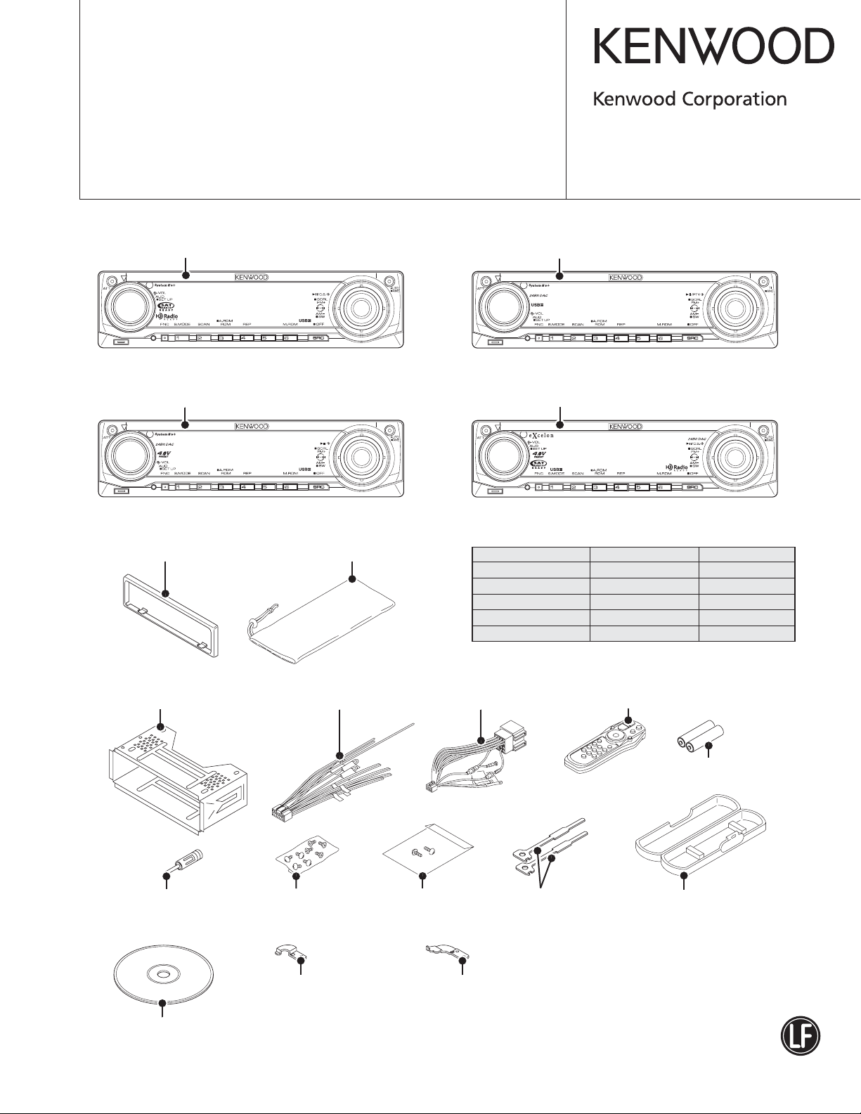
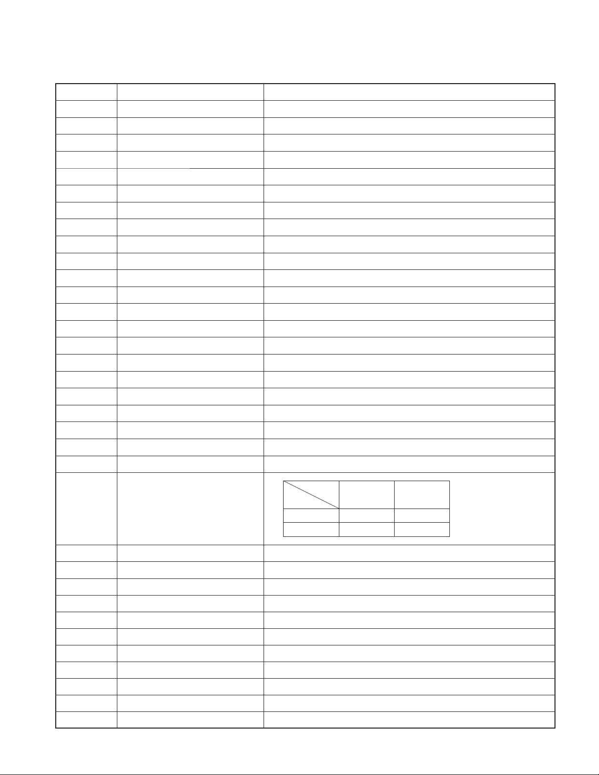
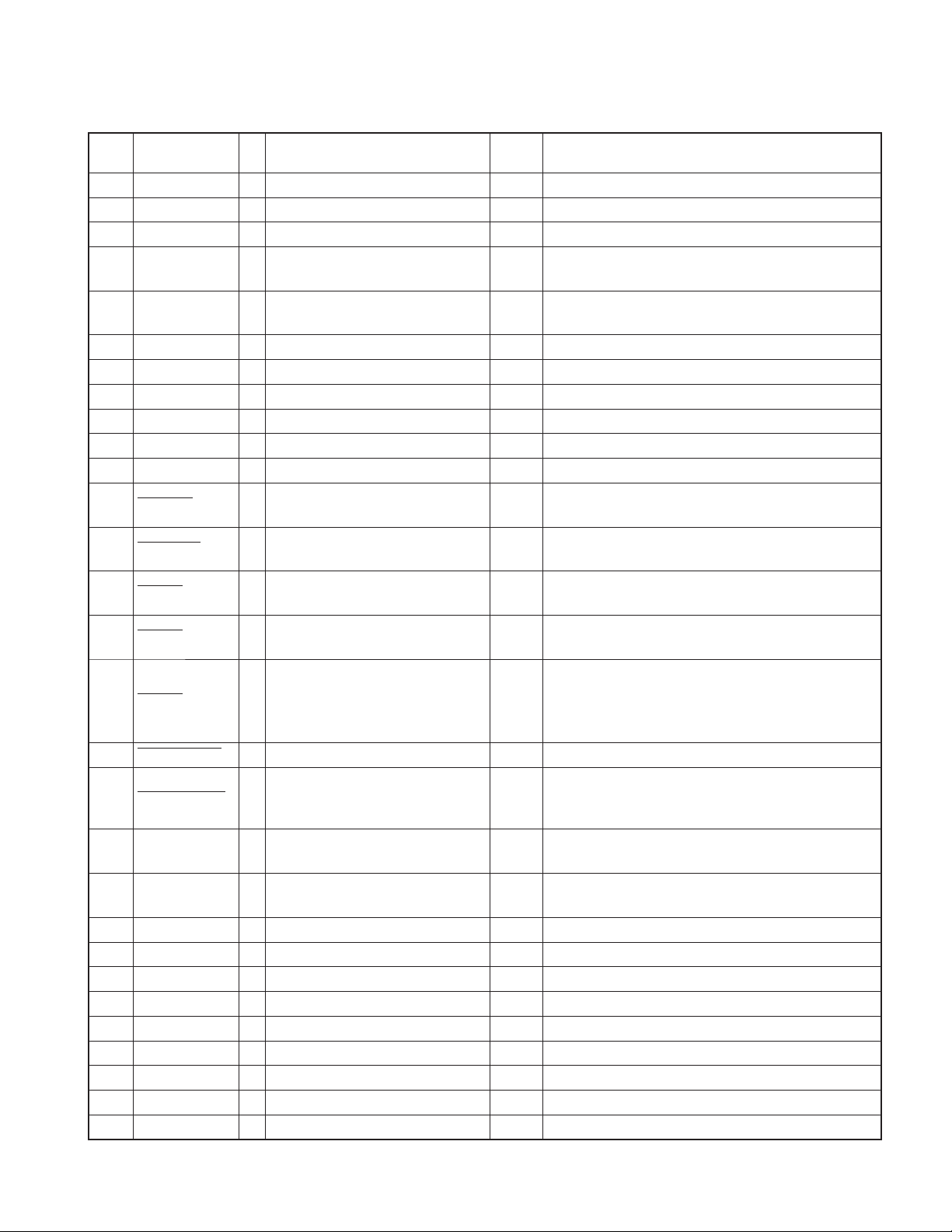
Panel assy
KDC-MP735U (A64-4020-01)
Panel assy
KDC-X7006U (A64-4022-01)
* Escutcheon
(B07-xxxx-xx)
KDC-MP735U
KDC-X7006U
* Carrying case
(W01-xxxx-xx)
Panel assy
KDC-W7537U/W7537UY (A64-4021-01)
KDC-W7537U
Panel assy
KDC-X791 (A64-4019-01)
KDC-X791
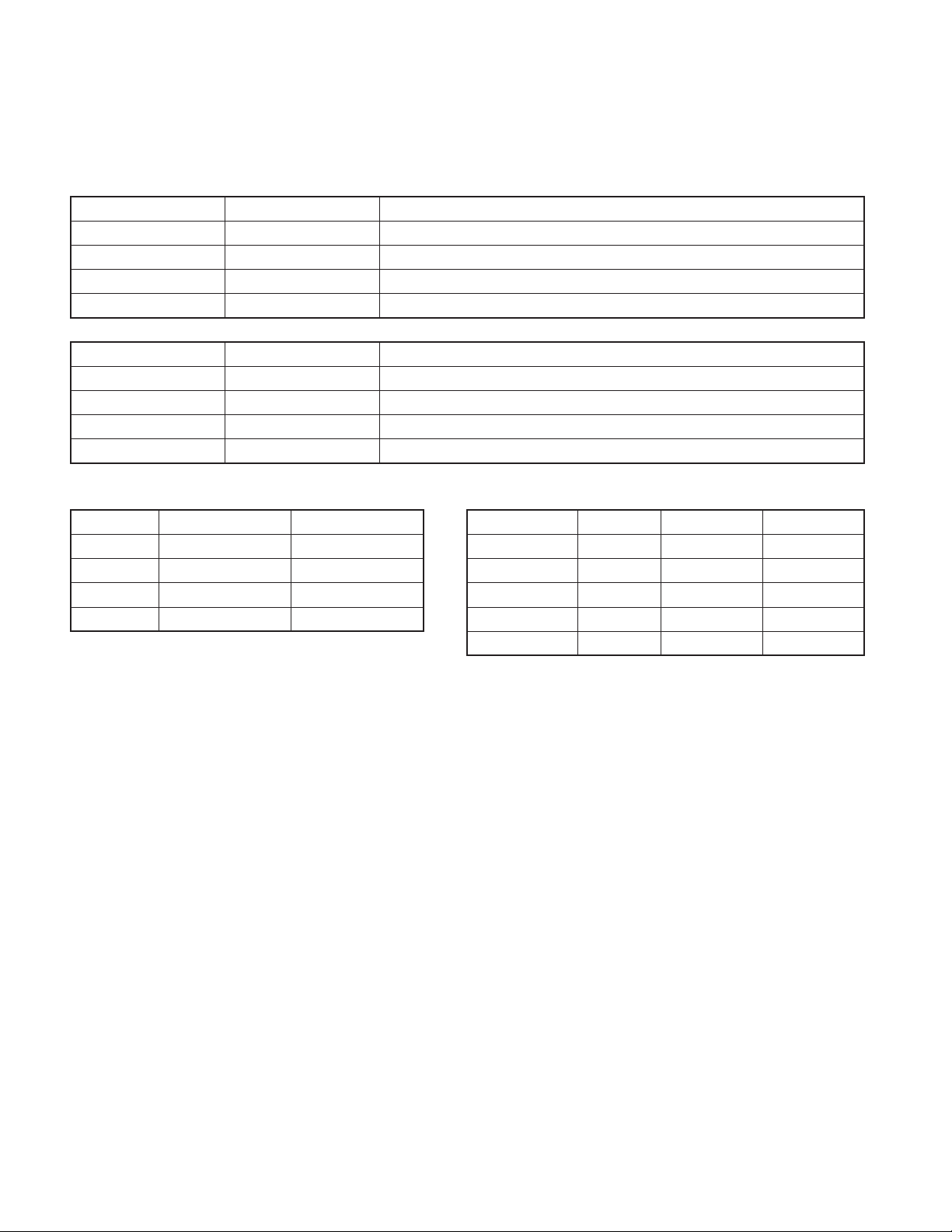
SPARE TDF PANEL
MAIN UNIT NAME TDF PARTS No. TDF NAME
KDC-MP735U Y33-2700-63 TDF-MP77D
KDC-W7537U Y33-2700-65 TDF-W7537U
KDC-W7537UY Y33-2700-65 TDF-W7537U
KDC-X7006U Y33-2700-66 TDF-X7006U
KDC-X791 Y33-2700-64 TDF-77DX
Mounting hardware assy
(J22-0011-03)
* Antenna adaptor
(T90-0523-05)
Compact disc
(W01-1690-05)
* DC cord
(E30-xxxx-xx)
* Screw set
(N99-1757-05)
Mounting hardware (L)
(J22-0258-04)
* Depends on the model. Refer to the parts list.
Screw set
(N99-1780-05)
* DC cord
(E30-6412-05)
Mounting hardware (R)
(J22-0259-04)
This product complies with the
* Remote controller assy (RC-547)
(A70-2085-05)
Lever
(D10-4589-04) x2
This product uses Lead Free solder.
Battery
(Not supplied)
* Plastic cabinet assy
(A02-2736-03)
RoHS directive for the European market.
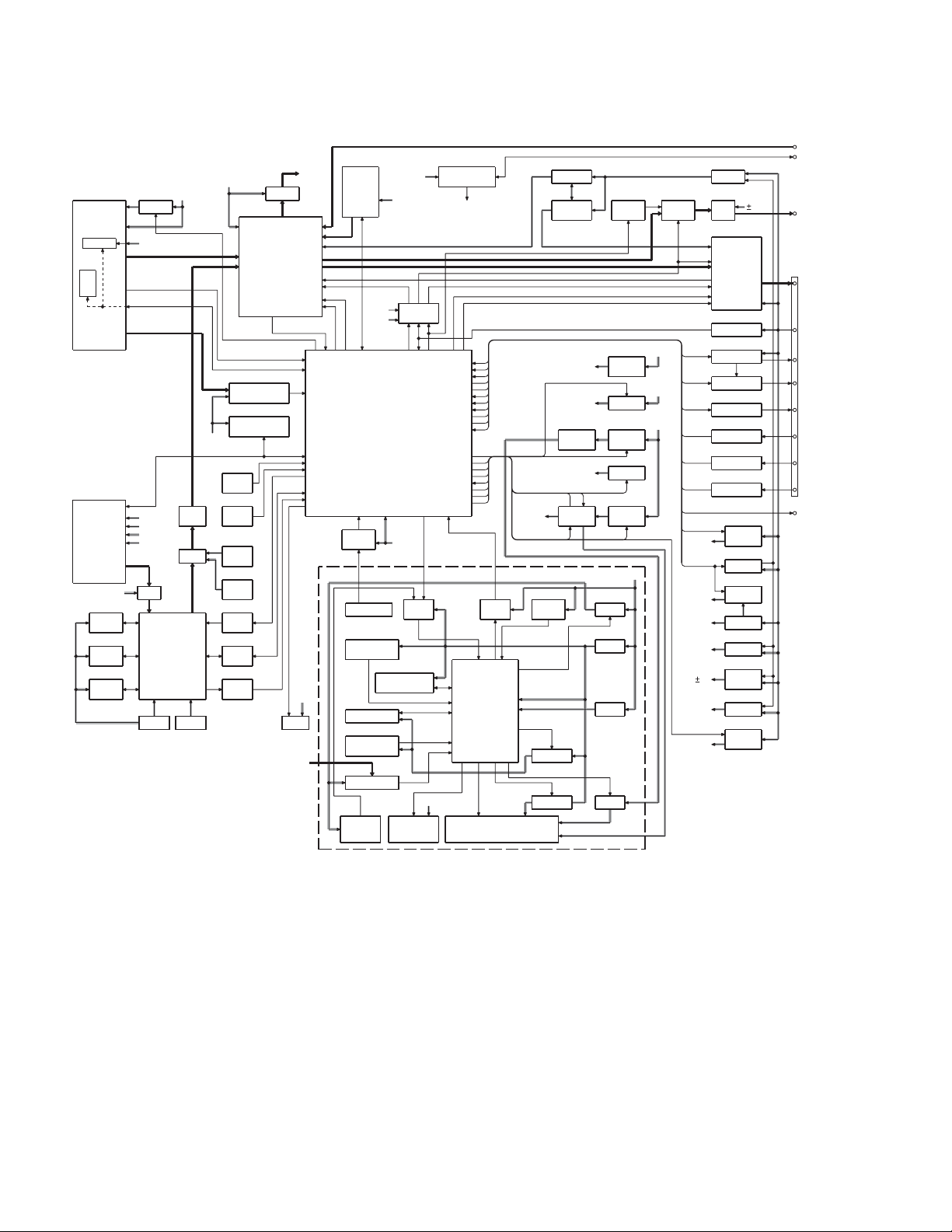
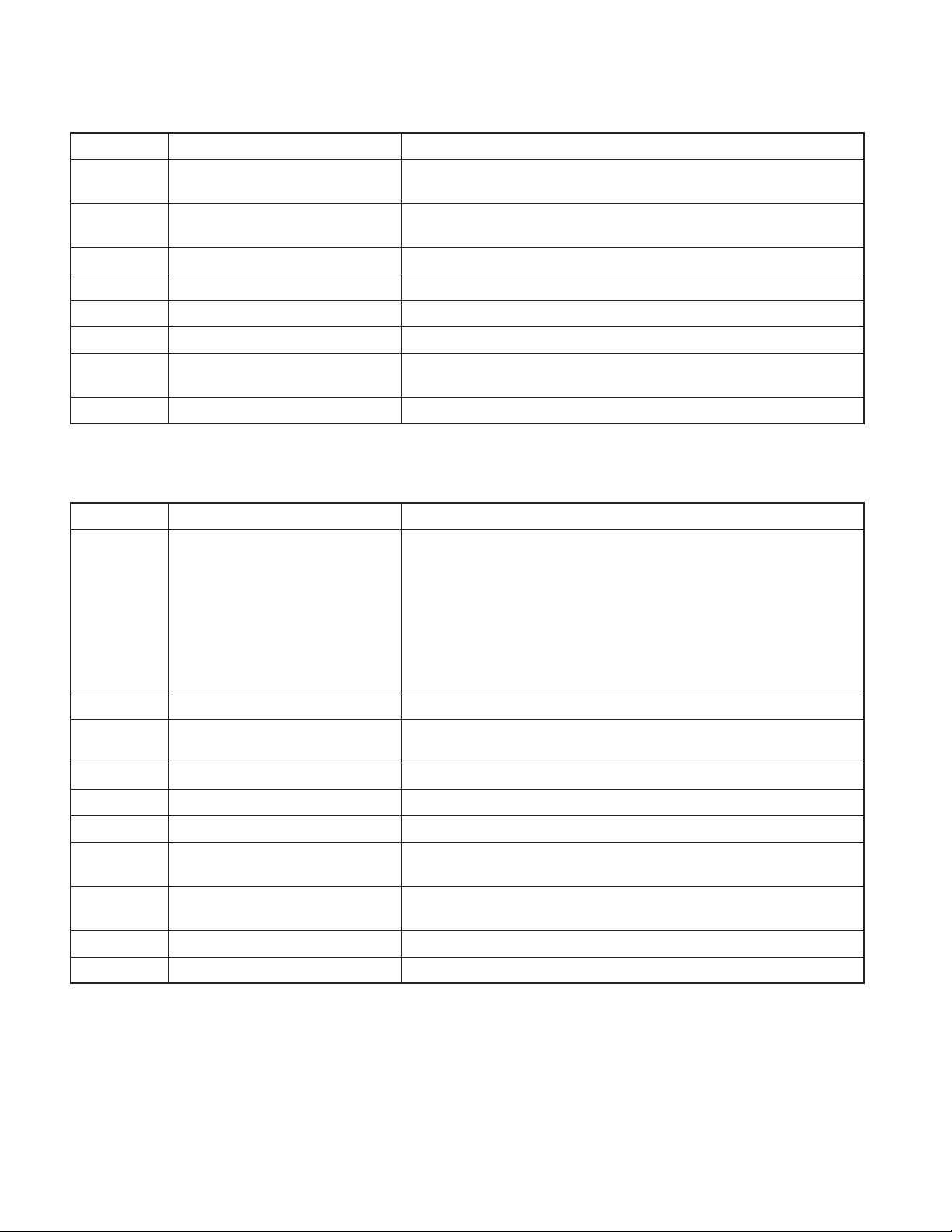
KDC-MP735U/W7537U
/W7537UY/X7006U/X791
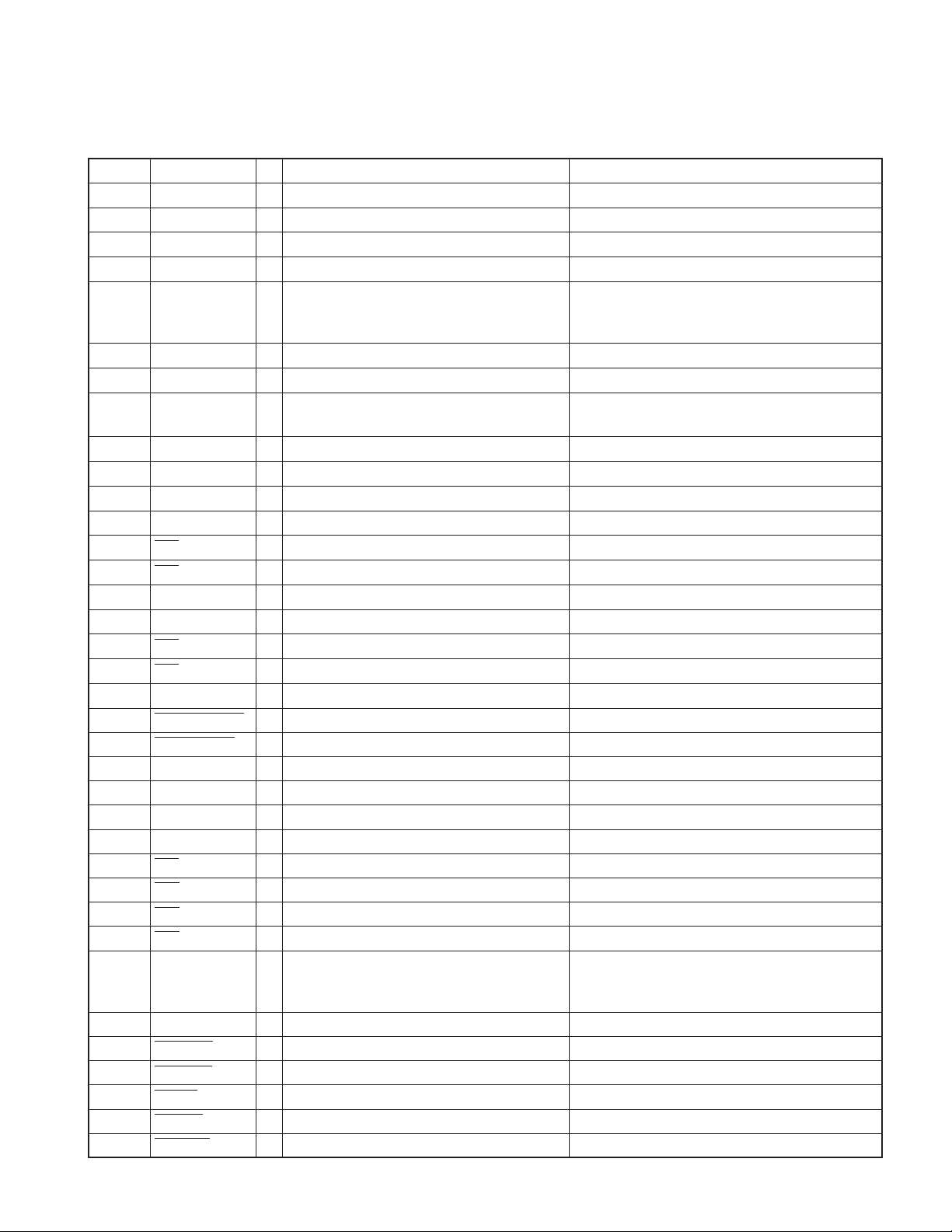
ELECTRIC UNIT (X34- )
SPE-
IC320
Q650
AGC
E-VOL
DCERR
ANA
AUX
WININ
MUTE 0,1,2
MUTE A
MUTE C
BU5V
DSI
SPE-
ANA
CH
FRONT-END
(FST)
E2PROM
FST
DME1
CD
IC702
iPod
I/F
IC714
SD
RAM
IC715
NOR
FLASH
Q400,401A400
SW5V
MPX
for
RDS
BU5V
A8V
SERVO
D5V
DIR
D3.3V
IC708 IC716
D3.3V D1.8V
AM+B
IC703
IC711
SOC
A8V
PRE
BUFF
DAC
SW5V
IC704
IC701
A8V
IC480
FM/AM
CD or MD
IC340
RDS
DECODER
IC520
ROM
CORRECTION
S651
EJECT
SW
S650
PAN E L
DET
IC707
DAC
D5V
IC717
DAC
A5V
IC709
LEVEL
SHIFT
IC712
LEVEL
SHIFT
IC710
LEVEL
SHIFT
BLOCK DIAGRAM
J420
LX BUS
Q530
RST
BU5V
IC500
MUTE A
MUTE C
SYSTEM
u-COM
IC510
RESET
IC BU5V
IC5
RESET SW
KEY
KEY MATRIX
IC3
ROM
CORRECTION
IC1
FLASH ROM
S19
ROTARY
ENCODER
IC2
SPE ANA
IC6 ED1
REMOTE
USB5V
BACK
UP
MUTE
DRIVER
RST
LEVEL
KEY ILL
ILL+B
CN200
CONNECTOR
USB I/F
to CD MECHA
MUTE 0,1,2
PWICMUTE
IC4
5P
STBY
LEVEL
SHIFTSHIFT
PAN E L
u-COM
USB5V
IC8IC7
Q9,10 Q11,13
FL
IC100
A3.3V REF+B
IC101 Q361,362 Q363-368 IC361-363
SVR REF
SVR+B
SERVO
DC/DC
(FL)
IC300
HI-SIDE
SW
IC5
RESET
IC
Q6
SW 3.3V
D5V
Q30,31
Q7,8
SW 5V
IC11
D 3.3V
IC10
D 2.5V
FL+BFL 3.3V
SW
MUTE
IC100
SERVO
Q60,61IC60
SW
FL+B
CD 5V
IC80
USB 5V
FDC
PAN 5 V
3.3V
SW5V
SERVO+B
SW20V
PRE
MUTE AMP
PAN 5 V
SW5V
BU5V
A8V
SW20V
ILL+B
Q100,101,103
OP
IC450
POWER
IC
OFFSET
Q120
BU DET
IC140
P-CON
Q150,151
ANT-CON
Q160
EXT AMP
Q180
DIMMER
C170,R170,D170
TEL MUTE
Q122
ACC DET
Q43
PAN E L
5V
Q32
SW 14V
Q22,23
SW 5V
Q20,21
BU5V
Q10,11
A8V
IC350
DC/DC
9V
(5VPRE)
Q70-72
SW 20V
Q50-52
ILL+B
J410
AUX IN
USB
CN200
CN361
9V
PRE OUT
(F/R SW)
J1
SP OUT
(FL/FR/RL/RR)
BACK UP
P CON
ANT CON
EXT.AMP.CON
DIMMER
LINE MUTE
ACC
CN190
WIRED REMOTE
OPEL DISP
SWITCH UNIT (X16- )
2
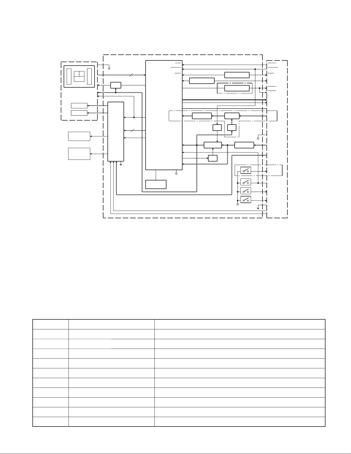
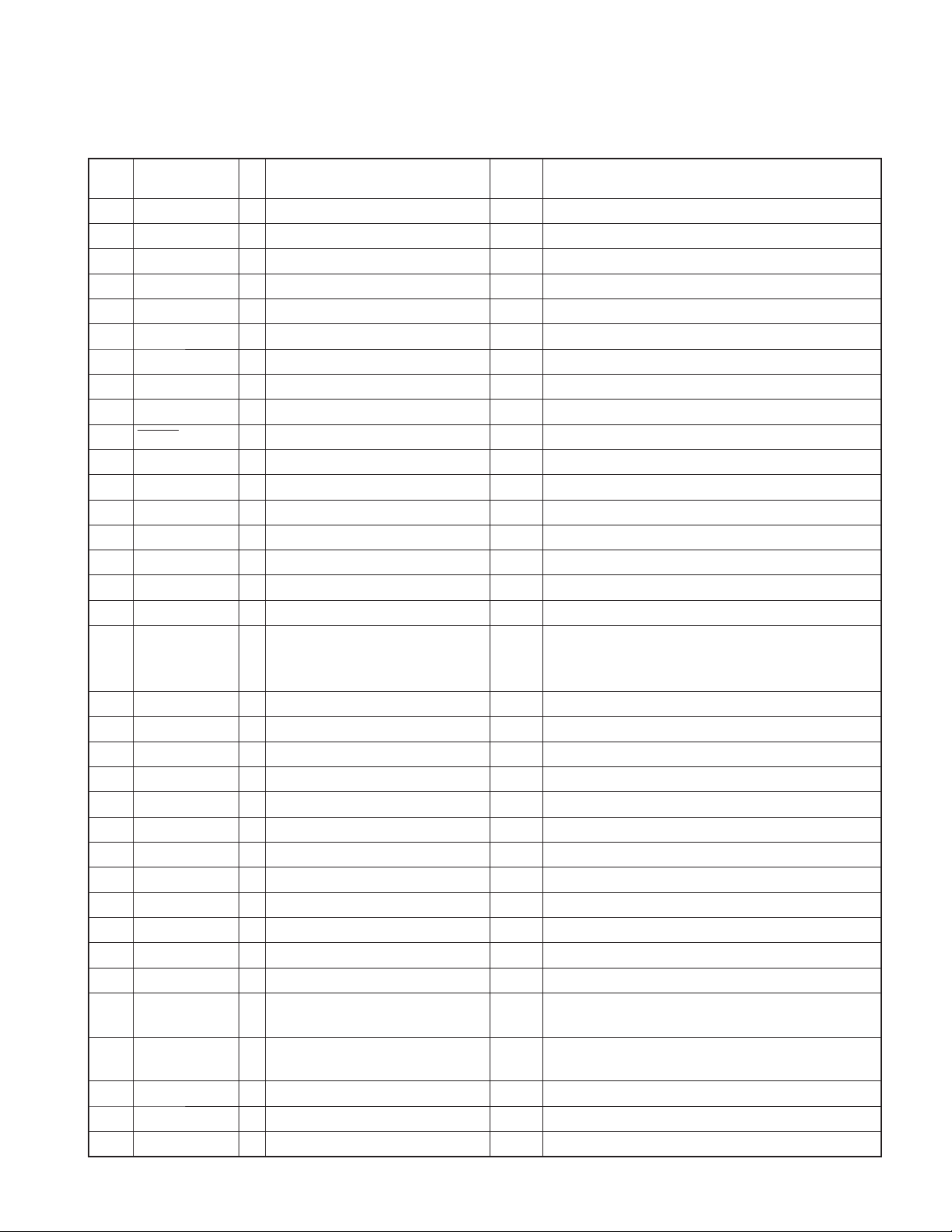
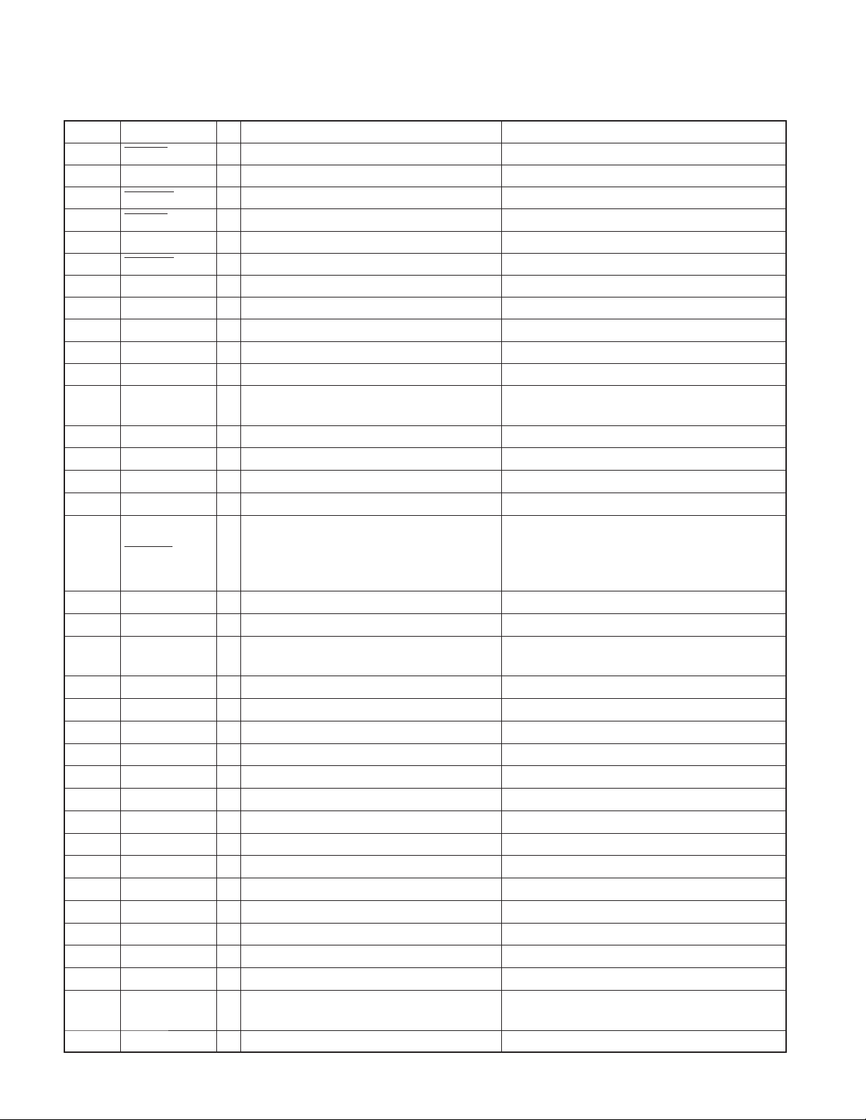
BLOCK DIAGRAM
KDC-MP735U/W7537U
/W7537UY/X7006U/X791
DPU1
A
E
C
FO COIL
TR COIL
DM1
SPINDLE
MOTOR
DM2
LOADING &
SLED
MOTOR
CD PLAYER UNIT (X32-598x-xx)
IC1
D.G ND
Q7
APC
IC6
FO OUT
TR OUT
MOTOR
DRIVER
DM OUT
FM OUT
VREF
S.GND
A,B,C,E,F
FOD,TRD,
TVD,SPL
1 CHIP IC
RF AMP
+
SERVO
PROCESSOR
+
MICRO
PROCESSOR
VREF
DMUTE
X1 or
X2
CLOCK
16.93MHz
B
F
RST
MSTOP
CLK
DATA
AVD D
IOVDD
P-ON1
REGVDD
D.G ND
LEVEL SHIFT
IC3
3.3V REG
Q8,9
Q6
3.3V SW
SW
Q3
LEVEL SHIFT
Q3
Q4
LEVEL SHIFT
(0-00),(0-01) ONLY
8V SW
SW
SW
Q1
Q2
(0-00),(0-01)
ONLY
IC2
3.3V REG
(0-01),(0-03)
ONLY
D.G ND
D.G ND
S.GND
S4
S3
S2
S1
MOTHER
BOARD (X34- )
MRST
MSTOP
CLK
DATA
MUTE
MUTE
L-ch
R-ch
A.GND
AS8V
D.G ND
BU5V
S7V
8EJE-SW
LOE/LIM-SW
12EJE-SW
LOS-SW
S.GND
LO/EJ
MOTOR
COMPONENTS DESCRIPTION
SWITCH UNIT (X16-391x-xx)
●
Ref. No. Application / Function Operation / Condition / Compatibility
IC1 ROM IC / Flash ROM IC Graphic data is included / For customization.
IC2 Spectrum Analyzer IC 6-ch band pass fi lter.
IC4 Panel µ-COM
IC5 Reset IC When panel is attached, IC5 is activated.
IC6 Remote Control IC Remote control receiver.
IC7 Level Shift It changes into 3.3V from 5V.
IC8 Level Shift It changes into 5V from 3.3V.
IC9 Level Shift For Control of ED1.
IC10 2.5V REG Power supply For 2.5V.
IC11 3.3V REG Power supply For 3.3V.
3
KDC-MP735U/W7537U
/W7537UY/X7006U/X791
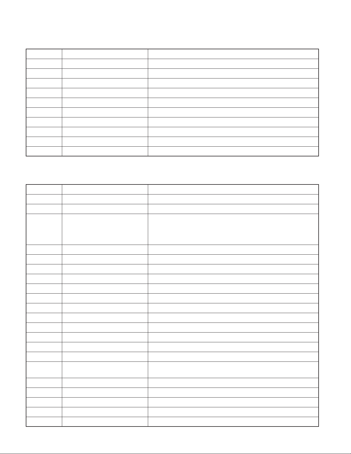
COMPONENTS DESCRIPTION
Ref. No. Application / Function Operation / Condition / Compatibility
Q1 Triangle GREEN LED SW Triangle GREEN LED lights when Q1’s base level goes Hi.
Q2 Triangle RED LED SW Triangle RED LED lights when Q2’s base level goes Hi.
Q3 BLUE LED SW BLUE LED lights when Q3’s base goes Hi.
Q4 GREEN LED SW GREEN LED lights when Q4’s base goes Hi.
Q5 RED (BLUE) LED SW RED (BLUE) LED lights when Q5’s base goes Hi.
Q6 SW3.3V SW SW3.3V is supplied to IC1 and IC3, when Q6’s base goes Lo.
Q7,8 SW5V SW SW5V is supplied to IC2 and IC6, when Q8’s base goes Hi.
Q9,10 FL3.3V SW FL+3.3V (VDD1) is supplied to FL display when Q9’s base goes Hi.
Q11,13 FL+B SW FL+B (VDD2) is supplied to FL display when Q11’s base goes Hi.
Q12 FL BLK SW ED1 lights when the base goes Hi.
ELECTRIC UNIT (X34-472x-xx)
●
Ref. No. Application / Function Operation / Condition / Compatibility
IC10 A8V REF Power Supply Outputs 1.27V.
IC60 SW Regulator Power supply for VFD (60V).
Power supply for VFD USB5V and MECHA digital.
IC80 SW Regulator CONT
IC100 A3.3V REF Supply A3.3V REF supply to E-VOL and all low pass fi lters.
IC101 SVR6.8V REF Supply SVR6.8V REF supply to power IC.
IC102 Discharge SVR6.8V SVR6.8V REF discharge from power IC.
IC140 Power Control IC Power control switch.
IC300 Power Control IC USB power control switches with over current detection and protection.
IC310 G-Analyzer Analog gravity sensor.
IC320 Spectrum Analyzer Buffer AMP & AGC Buffer and auto gain control for spectrum analyzer.
IC340 RDS Decoder Decodes RDS.
IC350 ±9V AVR Power supply for 5V Pre-out OP-AMP.
IC361~363 5V Pre-out AMP Output buffer and gain control.
CH1: VFD & USB5V (5.1V)
CH2: SOC digital (5.1V)
CH2: MECHA digital (5.1V)
IC450 Power IC Amplifi es the front L/R and the rear L/R to 50W maximum.
IC480 E-VOL & Source Selector Controls the source, volume, and tone.
IC500 System µ-com
IC510 Reset IC Lo when detection voltage goes below 3.6V.
IC520 E2PROM For installer memory.
IC530 Muting Logic IC Controls logic for muting.
IC701 D/A Converter Converts audio signal digital to analog.
IC702 iPod Authentifi cation IC Issues key code for control iPod
Controls FM/AM tuner, the changer, CD/USB mechanism, SOC, panel, volume
and tone.
4
KDC-MP735U/W7537U
/W7537UY/X7006U/X791
COMPONENTS DESCRIPTION
Ref. No. Application / Function Operation / Condition / Compatibility
IC703 DIR Audio data converter S/PDIF to I2S.
IC704 Low Pass Filter Low pass fi lter for audio output of IC701.
IC705 DAC D3.3V Supply When pin1 and pin5 go Hi, 3.3V is output.
IC708 SOC 3.3V Supply When pin1 goes Hi, 3.3V is output.
IC709,710 Level Shift 3.3V to 5V.
IC711 SOC (System On Chip) Controls mechanism, USB host and audio decoding.
IC712 Level Shift 5V to 3.3V.
IC714 Buffer RAM for SOC For buffering program and audio data.
IC715 Program ROM for SOC SOC fi rmware is installed.
IC716 SOC 1.8V Supply When pin1 and pin3 go Hi, 1.8V is output.
IC717 DAC A5V Supply When pin1 and pin5 go Hi, 5V is output.
Q10,11 A8V AVR When Q11’s pin2 goes Hi, A8V AVR outputs 8.0V.
Q12 SW14V When pin2 goes Hi, SW14V outputs 14V.
Q20,21 BU5V AVR While BU is applied, BU5V AVR outputs +5V.
Q22,23 SW5V When Q23’s base goes Hi, SW5V outputs +5V.
Q30,31 Servo+B AVR When Q31’s base goes Hi, Servo+B AVR outputs 7.5V.
Q32 SW14V When Q12’s pin2 goes Hi, SW14V outputs 14V.
Q40~42 PAN5V AVR When Q42’s pin2 goes Hi, PAN5V AVR outputs 5V.
Q43 PAN5V Discharge SW When Q43’s base goes Hi, PAN5V is discharged.
Q50~52 ILL AVR When Q52’s pin2 goes Hi, ILL AVR outputs 10.5V.
Q60,61 SW FL+B When Q61’s base goes Hi, SW FL+B outputs (BU-0.6)V.
Q70~72 SW16V (Surge Protection) When Q72’s pin2 goes Hi, SW16V outputs (BU-0.6)V.
Pin2
Q80 SW REG FREQ CONT SW (IC80)
Q81 VFD&USB5V AVR SW When the base goes Hi, VFD & USB5V AVR are on.
Q82 MECHA Digital AVR SW When the base goes Hi, MECHA digital AVR is on.
Q100,101,103 REF+B AVR When Q101’s base goes Hi, AVR outputs 13V.
Pin1
L 430kHz 600kHz
H 650kHz 820kHz
LH
Q104,105 SVR Discharge Driver When Q104’s base goes Hi, Q105 discharges SVR.
Q120 BU DET SW When Q120’s base goes Hi, BU voltage is detected.
Q122 ACC DET SW When Q122’s base goes Hi, ACC voltage is detected.
Q123 Surge DET SW When Q123’s base goes Hi, surge voltage is detected.
Q150,151 Power ANT SW When Q151’s base goes Hi, power antenna switch outputs 14V.
Q160 EXT-AMP Control Buffer Buffer for output.
Q180 Small-lamp DET SW When Q180’s base goes Hi, small-lamp is detected.
Q320 Spectrum Analyzer AGC CONT
When this circuit has an excessive input, a return is hung and an output is reduced.
5
KDC-MP735U/W7537U
/W7537UY/X7006U/X791
COMPONENTS DESCRIPTION
Ref. No. Application / Function Operation / Condition / Compatibility
Q352~354 Pre-amp –9V AVR
Q356~358 Pre-Amp +9V AVR
Q361,362 Pre-out Mute Driver When a base goes Lo, mute driver is turned on.
Q363~368 Pre-out mute SW When a base goes Hi, pre-out is set to mute.
Q400,401 AM+B SW When Q401’s base goes Hi, AM+B is output.
Q500,501 Panel DET SW When Q501’s base goes Lo, panel is detected.
Q650 DSI Driver
Q704,706 MRST Buffer When Q704 base goes Lo, Q706 outputs 0V.
Q352 and Q353 work as a differential amplifi er, Q354 works as a driver and
-9.1V is supplied to OP AMP for pre-out.
Q356 and Q357 work as a differential amplifi er. Q358 works as a driver and
+9.4V is supplied to OP AMP for pre-out.
DSI lights when the base is Lo. DSI turns off when the base is Hi. DSI turns on
and off when panel is taken off.
CD PLAYER UNIT (X32-5980-02)
●
Ref. No. Application / Function Operation / Condition / Compatibility
Focusing, tracking, sled and spindle servo processing.Automatic adjustment
(focusing, tracking, gain, offset and balance) operations. Digital signal processing
CD Signal Processor & MECHA
IC1
IC2 3.3V REG Supplies 3.3V to IC1 and the laser pick-up.
IC6 4ch BTL Driver
Q3 5V-3.3V Level Shift Shifts 5V to 3.3V, or 3.3V to 5V.
Q6 BU3.3V SW Q6 is ON when Q8 or Q9 is ON.
Q7 APC (Auto Power Control) Drives LD (Laser Diode).
Q8 Power Supply Control
Q9 Power Supply Control
D1,2 5V Force Voltage Prevention 5V Force Voltage Prevention from MECHA µ-COM side.
D3 Laser Diode Protection Prevents reverse bias which is applied to laser. Laser destruction prevention.
µ-COM RF Amplifi er responding to
CD-RW
(DSP, PLL, sub-codes, CIRC error correction, audio data interpolation
processing) operations, and microcomputer function. Generation of RF signal
based on the signals from the APC circuit and the laser pick-up, and generation
of servo error (focusing error and tracking error) signals. Detection of dropout,
anti-shock, track crossing and off-tracking conditions, included gain control
function during CD-RW.
Focusing and tracking coil, sled and spindle motor driver, disc loading and eject
operation.
Power Supply Control from MECHA µ-COM. Q6 is ON when pin 63 (P ON1) of
IC1 is Hi.
Power Supply Control from system µ-COM. Q6 is ON when pin 125 (MSTOP) of
IC1 is Hi.
6
KDC-MP735U/W7537U
/W7537UY/X7006U/X791
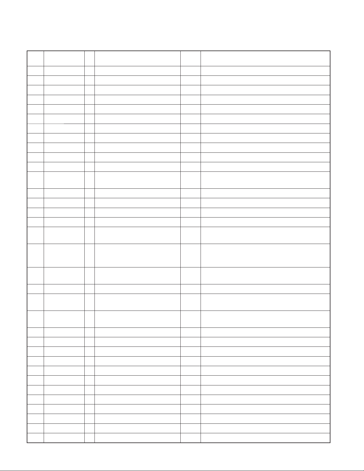
MICROCOMPUTER’S TERMINAL DESCRIPTION
SYSTEM µ-COM: IC500 on X34- (ELECTRIC UNIT)
●
Pin No.
1 WIRED REMO I Remote control input Pulse width detection
2 LX REQ M O Communication request to slave unit
3 LX MUTE I Mute request from slave unit H: Mute ON, L: Mute OFF
4 LX CON O Start-up request to slave unit H: Slave unit ON, L: Slave unit OFF
5 LX RST O Forced reset to slave unit H: Reset, L: Normal condition
6 BYTE -
7 CNVSS -
8 XCIN - 32,768Hz
9 XCOUT - 32,768Hz
10 RESET -
11 XOUT - 12MHz
12 VSS -
13 XIN - 12MHz
14 VCC1 -
15 NMI I Not used
16 LX REQ S I Communication request from slave unit
17 RDS CLK I RDS clock input
Pin Name I/O Application
Truth
value table
Processing / Operation / Description
H: Panel opened, L: Panel closed
18 FLIP DET I Flip-down panel opened detection
19 PON AM I/O AM+B power supply control
20 TUN IFC OUT I Front-end IFC-OUT input H: Station found, L: No station
21 RDS AFS M I/O Noise detection time constant SW L: During AF search, Hi-Z: Normal condition
22 RDS QUAL I RDS decoder QUAL input
23 RDS DATA I RDS decoder data input
24 F SEL1 O IC80’s frequency setting 1
25 F SEL2 O IC80’s frequency setting 2
26 PWIC BEEP O Beep output 2kHz/1kHz
27 TUN SCL I/O Front-end I2C clock input/output 400kHz
28 TUN SDA I/O Front-end I2C data input/output 400kHz
29 PAN SYS DATA O Data of system µ-com → panel UART MAX500kHz
30 PAN PAN DATA I Data of panel → system µ-com UART MAX500kHz
31 PAN SYS REQ O
32 PAN PAN REQ I
33 S SYS DATA O Data of system µ-com → SOC 400kHz
34 S SOC DATA I Data of SOC → system µ-com 400kHz
35 S SOC CLK I Clock from SOC (Host is SOC) 400kHz
Communication request of panel →
system µ-com
Communication request of system
µ-com → panel
(When panel is opened, only panel power supply falls down,
but audio signal remains)
H: ON when AM is received, Hi-z: OFF in the other conditions
Refer to the truth value table
q
Refer to the truth value table
q
7
KDC-MP735U/W7537U
/W7537UY/X7006U/X791
MICROCOMPUTER’S TERMINAL DESCRIPTION
Pin No.
36 PANEL SW DET I Flip-down panel detached detection
37 EJECT I Eject key input H: Normal condition, L: Key pushed
38 NC - Output L fi xed
39 ROMCOR DET I ROM correction writing request H: Writing ROM correction is ready.
40 DSI I/O DSI control H: Lighting, Hi-Z: Wink off
41 CD DISC12 SW I 12cm CD detection L: 12cm CD
42 CD LOS SW I CD loading detection L: Eject completed
43 CD MUTE I Servo and DAC mute request L: Mute request, H: Normal condition
44 PAN SC CON O Panel operation control H: Normal condition, L: Panel stopped
45 SOC SRST O SOC reset H: Normal condition, L: Reset
46 SOC SSTOP O SOC stop H: Normal condition, L: SOC stopped
47 CD DISC8 SW I
48 CD LOE LIM SW I CD detection (Chucking detection) H: Loading completed, L: No disc
49 CD LOEJ I/O CD motor control
50 CD MOTOR O CD motor control
51,52 NC - Output L fi xed
53 SW VBUS I/O VBUS5V control
54 PON ILL O
56 PON FDC USB I/O
57 PON SOC I/O SOC D5V power supply L: ON, Hi-Z: OFF
58 P5V DIS I/O
59 PON PANEL I/O
60 VCC2 -
61 PON O Power supply control Power ON: H, Power OFF: L
62 VSS -
63 TYPE 1 I 5 kinds of A/D values
64 TYPE 2 I 5 kinds of A/D values
65 DIAG I/O P.CON over-current detection
66 P CON I/O P.CON control
67 OEM DISP DATA I/O External display data External display
68 OEM DISP CLK I/O External display clock External display
69 OEM DISP CE I/O External display control request External display
70 ANT CON O ANT-CON control TUNER source: H, POWER OFF: L, STANDBY source: L
71 EXT AMP CON I/O EXT-AMP control
Pin Name I/O Application
8cm CD detection
(Only for Japanese model)
Control of panel LED, FL display
fi lament power supply and FL display
bias power supply
FL display fi lament power supply and
USB5V power supply control
PANEL5V discharge control
(It assures reset when the power is off)
Panel µ-com power supply
(It needs during panel authentication)
Truth
value table
w
w
e
e
Processing / Operation / Description
Power OFF condition is made at the same time as the detection
Refer to the truth value table
Refer to the truth value table
H: ON, Hi-z: OFF
(It depends on the command instruction from SOC)
H: ON, L: OFF, Display blackout: OFF
Panel detached or opened: OFF
L: ON, Hi-Z: OFF
H: Discharge, Other conditions: Hi-Z
H: ON, Hi-Z: OFF, Panel detached or opened: OFF
Refer to the truth value table
Refer to the truth value table
POWER ON: H, POWER OFF: Hi-Z, STANDBY source: Hi-Z
.
8
KDC-MP735U/W7537U
/W7537UY/X7006U/X791
MICROCOMPUTER’S TERMINAL DESCRIPTION
Pin No.
72 ACC DET I ACC detection ACC found: L, No ACC: H
73 BU DET I Dropping voltage detection BU found: L, No BU or Momentary power down: H
74 ILLUMI DET I Dimmer illumination detection L: ON, H: OFF
75 S SYS REQ O
76 S SOC REQ I
77 PWIC MUTE O Power IC mute
78 PWIC STBY O Power IC standby POWER ON: H, POWER OFF: L
79 LINE MUTE I Line mute detection TEL mute: 1V or lower, NAVI mute: 2.5V or higher
80 PWIC DC DET I DC offset detection
81 E2P SDA I/O I2C clock for ROM correction Communication speed: 200k~400kHz
82 E2P SCL I/O I2C data for ROM correction Communication speed: 200k~400kHz
83 MUTE SA I/O
84 MUTE AFS I/O
85 MUTE 0 O IC480 front mute control
86 MUTE 1 O IC480 rear mute control
Pin Name I/O Application
System µ-com → SOC communication
request
SOC → System µ-com communication
request
IC480 mute A-control
(Spectrum analyzer mute)
IC480 mute C-control (AFS mute)
E-type model only
Truth
value table
Processing / Operation / Description
STANDBY source or Momentary power down: L, TEL mute: L
L: Mute-ON time constant independence setting (0.5ms)
Hi-Z: Normal condition
L: Mute-ON time constant independence setting (0.5ms)
Hi-Z: Normal condition
L: Mute-ON time constant independence setting (10ms)
Hi-Z: Normal condition
L: Mute-ON time constant independence setting (10ms)
Hi-Z: Normal condition
L: Mute-ON time constant independence setting (10ms)
87 MUTE 2 O IC480 SW mute control
88 MUTE PRE FR O External preout mute for front and rear 0-bit, Momentary power down: L
2 kinds of shock noise counter-
89 MUTE PRE SW O
90 G Y OUT I
91 G X OUT I
92 RDS NOISE I FM noise voltage detection
93 TUN SMETER I Meter voltage detection
94 AVSS -
95 REF CON - Not used
96 VREF - A/D analog reference voltage
97 AVCC -
98 LX DATA S I Data from slave unit
99 LX DATA M O Data to slave unit
100 LX CLK I/O LX-BUS clock
measures for external preout mute and
sub mute
G-analyzer Y-direction transfer value
detection
G-analyzer X-direction transfer value
detection
Hi-Z: Normal condition
(In conjunction with MUTE PRE SW / Countermeasure for
IC480 shock noise)
0-bit, Momentary power down: L
(In conjunction with MUTE 2)
9
KDC-MP735U/W7537U
/W7537UY/X7006U/X791
MICROCOMPUTER’S TERMINAL DESCRIPTION
Truth value table
Frequency transition
q
10kHz space
F SEL1 (pin24) F SEL2 (pin25) Reception frequency
L L 530k~690kHz, All reception conditions except AM source
H L 700k~1020kHz, 1390k~1530kHz
L H 1540k~1700kHz
H H 1030k~1380kHz
9kHz space
F SEL1 (pin24) F SEL2 (pin25) Reception frequency
L L Below 675kHz, All reception conditions except AM source
H L 684k~1017kHz, 1386kHz~1530kHz
L H 1539k~1629kHz
H H 1026k~1377kHz
CD motor control
w
CD MOTOR (Pin50) CD LOEJ (Pin49)
Standby L L
Eject H H
Load H L
Brake H Hi-z
Destination setting
e
MODEL
KDC-MP735U K1 2.5V 0V
KDC-X791 K 1.6V 0V
KDC-X7006U M1 1.6V 1.6V
KDC-W7537U E1 0V 2.5V
KDC-W7537UY E2 0V 3.6V
DESTINATION
TYPE 1 (Pin63) TYPE 2 (Pin64)
10
KDC-MP735U/W7537U
/W7537UY/X7006U/X791
MICROCOMPUTER’S TERMINAL DESCRIPTION
PANEL µ-COM: IC4 on X16- (SWITCH UNIT)
●
Pin No. Pin Name I/O Application Processing / Operation / Description
1~7 D14~D8 I/O Data input/output
8 3.3VDD - 3.3V
9 VSS -
10~17 D7~D0 I/O Data input/output
Lighting time (Brightness gradation) is controlled at
18 FLGCP1 O FL display color tone control
19 NC - Output L fi xed
20 SYS REQ I System µ-COM communication request input H: During data communication
21 SC CON I
22 FL BK O FL BK control H: FL display lights, L: FL display does not light
23 2.5VDD - 2.5V
24 VSS -
25 NC - Not used Output L fi xed
26 KS1 I/O Key scan output Output L, Hi-Z switching
27 KS2 I/O Key scan output Output L, Hi-Z switching
28 TDO O For debug No connection in normal operation
29 TDI O For debug No connection in normal operation
30 KS3 O Key scan output Output L, Hi-Z switching
31 KS4 I/O Key scan output Output L, Hi-Z switching
32 TRST I For debug H or L during debug
33 ROTARY1 CCW I Rotary 1 B-input (for VOL) 1-pulse/2-click, 15-puls/360°
34 ROTARY1 CW I Rotary 1 A-input (for VOL) 1-pulse/2-click, 15-puls/360°
35 TMS O For debug No connection in normal operation
36 TCM O For debug No connection in normal operation
37 3.3VDD -
38 EVSS -
39 KS5 I/O Key scan output Output L, Hi-Z switching
40 KR1 I Key return input
41 KR2 I Key return input
42 KR3 I Key return input
43 FLGCP2 O FL color tone control
44 PAN REQ O Panel communication request output H: During data communication
45 SYS DATA I Data input from system µ-com UART communication (500kbps)
46 PAN DATA O Data output from panel UART communication (500kbps)
47 FL CLK O FL display serial communication reference clock Reference clock (4.125MHz at 66MHz)
48 KR4 INT I Key return input Interruption is possible.
49 FL DATA1 O FL display serial control data SI1
System µ-COM communication / Panel operation
control
pulse intervals.
GCP=FLGCP1+FLGCP2
H: Panel operation
Lighting time (Brightness gradation) is controlled at
pulse intervals.
GCP=FLGCP1+FLGCP2
11
KDC-MP735U/W7537U
/W7537UY/X7006U/X791
MICROCOMPUTER’S TERMINAL DESCRIPTION
Pin No. Pin Name I/O Application Processing / Operation / Description
50 CLK IN3 I Serial synchronized clock input FL display clock is synchronized.
51 FL EN O FL display skip shift control H or Hi-Z: Odd skip, L: Even skip
52 FL DATA2 O FL display serial control data SI2
53 CLK IN2 I Serial synchronized clock input FL display clock is synchronized.
54 FL LAT O FL display latch control
55 FL DATA3 O FL display serial control data SI3
56 3.3VDD -
57 X2 I Clock input 6.6MHz (Inward: 66MHz)
58 X1 I Clock input 6.6MHz (Inward: 66MHz)
59 CVSS -
60 CKSEL I Operation mode input of clock generator To GND directly
61 PSEL I Input frequency selection signal input in PLL mode
62 2.5VDD -
63 VSS -
64 MODE0 I System µ-com operation mode input To GND directly
65 MODE1 I System µ-com operation mode input in debug test Writing: Hi
66 PAN RST I Input from reset IC
67 AVDD1 I D/A conversion reference voltage To D3.3V
68 TYPE3 I 64-COLOR / MONO destination setting H: MONO, L: 64-COLOR
69 TYPE2 I
70 AVSS1 - D/A conversion reference GND To GND directly
71 AVSS0 - D/A conversion reference GND To GND directly
72 AVDD0 I A/D conversion reference voltage To D3.3V
73 WAVE IN I Audio input AD reading
74 F06 I BPF (10kHz) AD reading
75 F05 I BPF (3.3kHz) AD reading
76 F04 I BPF (1kHz) AD reading
77 F03 I BPF (330Hz) AD reading
78 F02 I BPF (150Hz) AD reading
79 F01 I BPF (63Hz) AD reading
80 NC - Pull-down
81 2.5VDD -
82 VSS -
83 NC - Not used L fi xed
84 TYPE1 I
85 NC - Not used L fi xed
FLIP-DOWN PANEL / SLIDE PANEL destination
setting
Destination setting of customization function
existence
VDD connection is made if main clock is over 5.5MHz.
In other conditions, GND connection is made.
Cancel is made 100msec after POWER ON and
PANEL ON.
Reset is made 60usec after POWER ON and PANEL
OFF.
H: FLIP-DOWN PANEL, L: SLIDE PANEL
H: Flash ROM, L: Mask ROM
12
KDC-MP735U/W7537U
/W7537UY/X7006U/X791
MICROCOMPUTER’S TERMINAL DESCRIPTION
Pin No. Pin Name I/O Application Processing / Operation / Description
86 REMO I Remote control signal input Signal is detected at pulse intervals.
87 PON FL+B O FL display bias power supply SW H: ON, L: OFF
88 PON FLVDD I/O FL display logic block power supply SW H: ON, Hi-Z: OFF
89 PON 5V I/O 5V power supply SW
90~93 NC - Not used Output L fi xed
94 WE I/O Memory data writing permission L: Writing, H: Waiting, SW3.3 starts up: Hi-Z
95 OE I/O Memory data output permission L: Data output, H: Waiting, SW3.3 starts up: Hi-Z
96,97 NC - Not used Output L fi xed
98 3.3VDD -
99 VSS -
100 FROMCHK O For checking by factory engineer
101 CE I/O Memory operation permission L: Operating, H: Waiting, SW3.3 starts up: Hi-Z
102 NC - Not used Output L fi xed
103 ROTARY2 CCW I Rotary 2 B-input 1-pulse/2-click, 15-puls/360°
104 ROTARY2 CW I Rotary 2 A-input 1-pulse/2-click, 15-puls/360°
105 ROMCOR SCL I/O For ROM correction
106 ROMCOR SDA I/O For ROM correction
107 NC (SEL E2P) - Not used Output L fi xed
108 PON TRI GREEN I/O Triangle green lighting SW H: Lighting, Hi-Z: Wink out
109 PON TRI RED I/O Triangle red lighting SW H: Lighting, Hi-Z: Wink out
110 PON BLUE I/O Blue sub-illumination lighting SW H: Lighting, Hi-Z: Wink out
111 NC - Not used L fi xed
112 3.3VDD -
113 EVSS -
114 PON GREEN I/O Green key illumination lighting SW H: Lighting, Hi-Z: Wink out
115 PON RED,BLUE I/O Red and blue key illumination lighting SW H: Lighting, Hi-Z: Wink out
116 PON SW3V I/O
117 NC - Not used Output L fi xed
118~123 A21~A16 O Address output
124 2.5VDD -
125 VSS -
126~133 A15~A8 O Address output
134 3.3VDD -
135 EVSS -
136~142 A7~A1 O Address output
143 NC - Not used Output L fi xed
144 D15 I/O Data input/output
Chinese character ROM / ROM correction /
Rotary encoder power supply
Hi: ON, Hi-Z: OFF
(Remote control IC & Spectrum analyzer IC)
OK: H, NG: L (Hi and Lo are repeated before it is fi xed /
Check land is needed)
Input except in reading (Including STB),
SW3.3 starts up: Hi-Z
Input except in reading (Including STB),
SW3.4 starts up: Hi-Z
L: ON, Hi-Z: OFF
13

KDC-MP735U/W7537U
/W7537UY/X7006U/X791
TEST MODE
How to enter the test mode
●
Press and hold the [1] and [3] keys and reset. (While “– –
– –” is being displayed, power can be ON for 30 minutes.)
How to clear the test mode
●
Reset, momentary power down, Acc OFF, Power OFF,
detach the panel.
Test mode default condition
●
• Source is STANDBY.
• Display lights are all turned on.
• The volume is at 30 (-10dB).
• LOUD is OFF.
• CRSC is off regardless of the availability of switching
function.
• SYSTEM Q is NATURAL (=FLAT).
• BEEP is always activated by briefl y pressing a button.
• AUX is ON (Internal AUX supporting model).
• DISPLAY TYPE is TYPE C.
• TUNER source display shall be as shown below:
For European models
Upper row=PS/Frequency, Middle row=Spectrum
analyzer/Clock, Lower row=Date
For models of destination “K” and “M”
Upper row=SNPS, Middle row=Spectrum analyzer/
Clock, Lower row=Date
• CD/USB source display shall be as shown below:
For all models
Upper row=P-TIME, Middle row=Spectrum analyzer/
Clock, Lower row=Date
• SOURCE SELECT shall be 2.
Specifi cation of the test mode for tuner source
●
The frequency of 98.3MHz is received when the [4] key is
pressed in the TUNER FM mode..
(*1) Only in the test mode, [1] key, [2] key, [3] key, [4] key, [5]
key and [6] key shall be displayed on the multi-function
key.
1. Press the [FNC] key briefly to make the multi-function
display.
2. Rotate the control knob on the right side and use
the [ ]/[ ] keys to display the target key in the center.
3. Press the [ ] key briefl y to fi nalize the display.
(*2) Perform the same operations as above on the keys, [1],
[2], [3], [4], [5], and [6] of the remote controller.
Specifi cation of FST soft mute adjustment mode
●
1. Receive the TUNER FM mode in the VOLUME 30 and
LOUD OFF condition.
2. Press and hold the [ ] key for 2 seconds to enter the
FST soft mute adjustment mode.
3. In the adjustment mode, the following display is shown
and adjust the mute between 0 (18dBµ) and F (36dBµ)
with the [FM]/[AM] keys.
(Display) SMD—x_ _ _ (Adjustment value, 0~F is
displayed in “x”.)
4. When the adjustment is “OK”, press and hold the [ ]
key for 2 seconds again to write the adjustment value
in the E2PROM, and after the successful writing-in the
“EP_WRITE” is displayed.
5. Press the [ ] key briefl y to exit from the FST soft mute
adjustment mode. (The test mode continues.)
RBDS auto measurement
●
Add the process to replace the visual inspection of PS
display previously done in the production line.
When it is confi rmed that the PS data has been received
and that the content of the PS is “RDS_TEST”, force to
OFF the P-CON terminal. (The symbol, “_” indicates the
blank.)
Make this as the process dedicated for the test mode.
P-CON is recovered by Power OFF→ON.
Special display in tuner mode
●
Error is found in front-end, etc. if indications below are
displayed while in tuner mode.
• “TNE2P_NG” : Front-end E2PROM values are still default
(not determined).
• “TNCON_NG” : Cannot communicate with the front-end.
K3I forced switching
●
Every time when [6] key is pressed in tuner FM mode,
switched in the following order: AUTO→Forced WIDE
Forced MIDDLE→Forced NARROW→AUTO. Default
→
status is AUTO, and displayed as shown below.
• AUTO: FMA • Forced WIDE: FMW
• Forced MIDDLE: FMM • Forced NARROW: FMN
CD source test mode specifi cation
●
• Jumps to the following tracks by pressing the [ ] key.
9→15→10→11→12→13→22→14→9 (recursive)
Note that when playing a CD-DA and a MP3 / WMA / AAC
/ WAV discs with 8 fi les or less, the disc is played from the
1 track in the normal order.
14

TEST MODE
KDC-MP735U/W7537U
/W7537UY/X7006U/X791
• Pressing the [ ] key goes back by 1 track from the track
being played.
• While in CD source, press the [1] key briefl y ([1] key for
CD-DA and [FM] key) to jump to No.28.
• While in CD source, press the [2] key briefl y to jump to
No.14.
• While in CD source, press the [3] key briefl y to display CD
mechanism model name and the version in the upper row.
Press the [3] key briefl y again to go back to the normal
screen. (Time code display)
• While in CD source, press the [6] key briefl y ([6] key for
CD-DA, and [AM] key) to jump to No.15. At this time, the
volume value is set to 25 (2V PRE ), 27 (4V PRE).
(*1) Only in the test mode, [1] key, [2] key, [3] key and [6] key
shall be displayed on the multi-function key.
1. Press the [FNC] key briefly to make the multi-function
display.
2. Rotate the control knob on the right side and use the
[
]/[ ] keys to display the target key in the center.
3. Press the [ ] key briefl y to fi nalize the display.
(*2) Perform the same operations as above on the keys, [1],
[2], [3], and [6] on the remote controller.
• Bass/Middle/Treble Level are adjusted by the VOL knob
and [
• HPF Front/Rear is adjusted by the VOL knob and
[ ]/[ ] keys in 2 steps: Through↔180Hz (or 220Hz).
(Default value: Through)
• LPF Sub Woofer is adjusted by the VOL knob and
[ ]/[ ] keys in 2 steps: 60Hz (or 50Hz)↔Through.
(Default value: Through)
• Sub Woofer Phase is adjusted by the VOL knob and
[ ]/[ ] keys in 2 steps: Reverse↔Normal. (Default
value: Normal)
• Volume Offset (other than the internal AUX) is adjusted by
the VOL knob and [ ]/[ ] keys in 2 steps: -8↔0. (Default
value: 0)
• Volume Offset (internal AUX) is adjusted by the VOL knob
and [ ]/[ ] keys in 3 steps: -8↔0↔+8. (Default value: 0)
• Loudness ON/OFF is adjusted by the VOL knob and
[ ]/[ ] keys in 2 steps: OFF↔ON. (Default value: OFF)
• Dual Zone ON/OFF is adjusted by the VOL knob and
[ ]/[ ] keys in 2 steps: OFF↔ON. (Default value: OFF)
• Bass f/Bass Q/Bass EXT/Middle f/Middle Q/Treble f are
not displayed in the audio adjustment menu.
• SYSTEM Q (dB EQ) curve selection is not displayed in
the audio adjustment menu.
]/[ ] keys in 3 steps: -8↔0↔+8. (Default value: 0)
AUDIO adjust mode
●
• Press the [AUD] key briefl y to enter the audio adjustment
mode.
• Press the remote control [∗] key and [AUD] key to enter
the audio adjustment mode.
• Both AUDIO FUNCTION MODE and SETUP MODE
adjustment items are included.
• By pressing [AUD] and [FM] key briefl y, switch the item
to be adjusted in the following order. (Only in forward
rotation)
The default item shall be Fader, and then the item is
forwarded in the following order: Balance→Bass Level
Middle Level→Treble Level→HPF Front→HPF Rear
→
LPF Sub Woofer. (thereafter arbitrary)
• Continuous forwarding by remote control is prohibited.
• Fader is adjusted by the VOL knob and [ ]/[ ] keys in
3 steps: R15↔0↔F15. (Default value: 0)
• Balance is adjusted by the VOL knob and [ ]/[ ] keys
in 3 steps: L15↔0↔R15. (Default value: 0)
→
MENU
●
• Press the [FNC] key briefly to make the multi-function
display and press the [ ] key briefl y to enter the MENU.
• Press the remote control [DNPP/SBF] key and the
[DIRECT] key to enter the MENU.
• Continuous forwarding by remote control is prohibited.
• Only in the test mode, make the USB source MENU show
the F/W Version check item and make the F/W Version be
shown as the initial items in the test mode.
Dual Zone
●
• If the [AUTO] or [TI] keys is pressed briefly while in a
source other than STANDBY, Dual Zone is switched
between ON/OFF.
Backup current measurement
●
If reset while in Acc OFF (Back Up ON) condition, MUTE
terminal goes off 2 seconds later, rather than 15 seconds.
(During this time, the CD mechanism does not function.)
15
KDC-MP735U/W7537U
/W7537UY/X7006U/X791
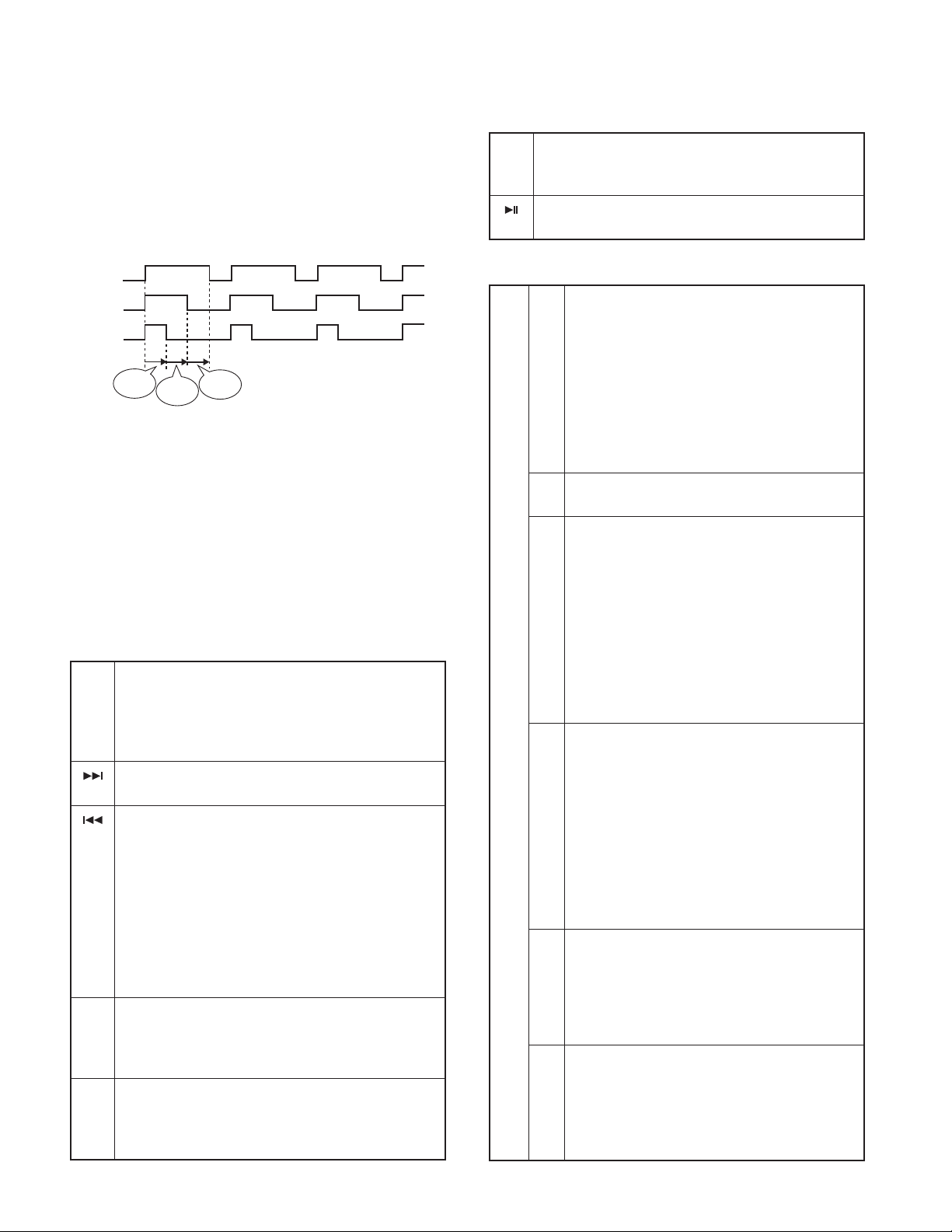
OPEL communication
●
(OPEL/OEM display supporting model)
OPEL communication line while in the test mode outputs
the following. (Communication line output condition is
switched every 500msec.)
TEST MODE
[1]~[6]
Key pressed briefl y: Version & Service information display
key
mode ON.
Refer to the Table 1.
∗
]
Key pressed briefl y: CD information display mode ON.
[
key
Refer to the Table 2.
∗
CE
DATA
CLK
500msec
G sensor display (G-Analyzer supporting model)
●
500msec
500msec
Press [ATT] key briefl y in the STANDBY source to change
to the analogue meter display that shows the vertical G
and horizontal G conditions.
Special displays while all lights are on
●
When all lights are on with STANDBY source, if the
following keys are pressed, the following messages are
displayed.
[FM]
Key pressed briefl y: ROM correction version is displayed.
key
(Display) R1234_ _ _
When E2PROM is not installed: ERR_ _ _ _ _
When not written in: R – – – – _ _ _
When data not matching: R
[ ]
Key pressed briefl y: Audio data initialization
key
(Display) AUD_INIT
[ ]
Key pressed briefl y: Forced Power OFF data displayed.
key
Press and hold: To clear the forced power OFF
information. (Press and hold for 2 seconds while the forced
power OFF data is displayed.)
(Display) POFF_ – – – (No Forced Power OFF)
SEC ( Forced Power OFF because of
missing Security Code)
PNL ( Forced Power OFF because
of system µ-com and panel
communication error)
[AUD]
Key pressed briefl y: iPod authentication IC installation
key
status display (iPod 2Wire supporting model).
(Display) iPod_OK_ (Installation status OK)
NG (Installation status NG)
[FNC]
Key pressed briefl y: Multi-function display.
key
Press and hold: Version & Service information display
mode ON
Refer to the Table 1.
∗
∗∗∗∗
_ _ _
Table 1- Version & Service information display mode
[1]
Key pressed briefl y: Version is displayed.
key
(Display) C0605WK__SYS1.23
(Display) STYPE : xx_PAN1.11
(Display) PTYPE : x_ _MEM3.21c
*1 STYPE indicates system µ-com destination,
and PTYPE indicates panel µ-com destination,
and show real-time condition of the destination
terminal.
[AM]
key
↑
↓
[FM]
key
*2 “c” at the end of Ver. of MEM indicates 2Color, “d”
of that indicates Mono.
[2]
Key pressed briefl y: Serial No. is displayed. (8 digits)
key
(Display) SNo_ЧЧЧЧЧЧЧЧ
[3]
Key pressed briefl y: Power ON time is displayed.
key
Press and hold: To clear Power ON time (Press
and hold for 2 seconds while the Power ON time is
displayed.)
(Display) PonTim_0H××_ ( 00~50 is displayed for “xx”.
When less than 1 hour,
display by increment of 10
minutes.)
ЧЧЧЧЧ ( 00001~10922 is displayed
for “xxxxxx”.)
MAX 10922 (hours)
[4]
Key pressed briefl y: CD operation time is displayed.
key
Press and hold: To clear CD operation time (Press
and hold for 2 seconds while the CD operation time
is displayed.)
(Display) CDTim_0H××_ ( 00~50 is displayed for “xx”.
When less than 1 hour,
display by increment of 10
minutes.)
ЧЧЧЧЧ ( 00001~10922 is displayed
for “xxxxxx”.)
MAX 10922 (hours)
[5]
Key pressed briefl y: Number of CD EJECT times is
key
displayed.
Press and hold: To clear CD EJECT times (Press
and hold for 2 seconds while the CD EJECT time is
displayed.)
(Display) EjeCnt_ЧЧЧЧЧ MAX 65535 (times)
[6]
Key pressed briefl y: Number of times panel is
key
opened/closed is displayed.
Press and hold: To clear PANEL open/close count
(Press and hold for 2 seconds while the PANEL
open/close time is displayed.)
(Display) PnCnt_ЧЧЧЧЧ MAX 65535 (times)
16
 Loading...