

Kenwood KDC-M7024, KDC-MP822 Service Manual
CD RECEIVER
KDC-M7 024
KDC-MP822
SERVICE MANUAL
© 2003-2 PRINTED IN JAPAN
B53-0035-00 (N) 3114
CD mechanism operation description is
not in this service manual.
Please, refer to service manual X924030-0x (B51-7867-00).
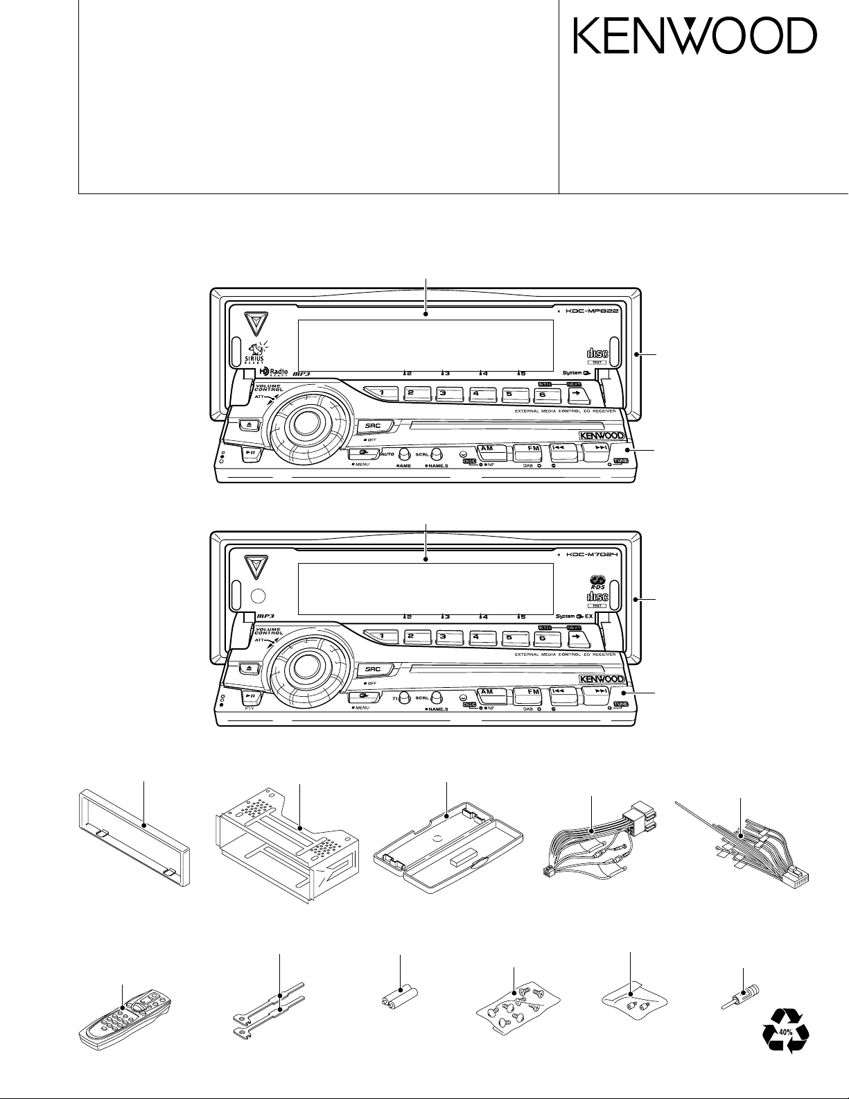
Panel assy
(A64-2978-01): KDC-MP822
Panel assy
(A64-2986-01): KDC-M7024
CD mechanism extension cord : W05-0935-00
50 4W
COMPACT
DIGITAL AUDIO
50 4W
COMPACT
DIGITAL AUDIO
Escutcheon
(B07-3078-01)
Panel assy
(A64-2995-02):
KDC-MP822
Escutcheon
(B07-3078-01)
Escutcheon
(B07-3078-01)
Remote controller assy
(RC-505)
(A70-2040-05)
: KDC-MP822
Mounting hardware assy
(J21-9823-03)
Lever
(D10-4674-04) x 2
Plastic cabinet assy
(A02-2731-03)
Size AA battery
(Not supplied)
DC cord (ISO)
(E30-4942-05)
: KDC-M7024
Screw set
(N99-1723-05)
: KDC-MP822
Panel assy
(A64-3003-02):
KDC-M7024
Screw set
(N99-1734-05)
DC cord
(E30-6106-05)
: KDC-MP822
Antenna adaptor
(T90-0552-05)
: KDC-M7024
KDC-M7024/MP822
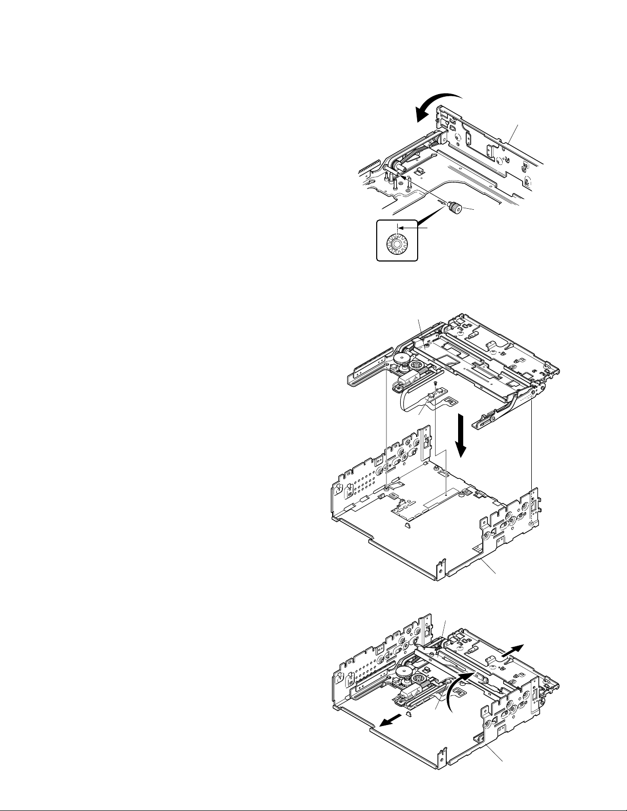
HOW TO THE PANEL MECHANISM ASSEMBLY
1. Fixed the position of operation side
(Fixed the horizontal position when the panel opened)
q The mounting hardware (281) of operation side is rota-
tion (A) into the stop position with close side.
w As figure (B) line is just above and the gear (230) at-
tached to pin.
2. The slider assembly insert to bottom chassis
q The bracket for display panel (284) is leave down, in-
sert to the chassis (702). (C)
A
Rotary to the
stop position
B
This line attached just above
Fig. B
(This figure from look at B arrow)
284
281
230
w The slider assembly insert to the chassis (702) after
that shift (D) direction.
e The bracket for display panel (284) is raised (E) direc-
tion.
r Keep the raising conditions, the slider assembly is shift
(F) direction.
(Note) Do not bend the knob of chassis detection switch
when the slider assembly insert.
SW
C
702
284
F
E
SW
D
702
3

BLOCK DIAGRAM
KDC-M7024/MP822
(X25-966)
TUNER
AUDIO OUT
Q102,103
AM+B
8V 8V
8V
S-METER
CD
BU5V
8V
SERVO
CD4.7V
CH
BACK UP
BU5V
Q501
EEP5V
IC1
EEPROM
TDF UNIT (X16-208)
Q104
BUFFER
IC12
RDS
DECODER
SW5V
BU5V
IC1
Q53
BUFFER
SW5V
u-COM
IC2
FM
AM
CD
CH
QUAL
8V
E-VOL
&
MPX
IC8
MUTE
DRIVER
Q59,60
PRE MUTE
Q57,58
PRE MUTE
Q55,56
PRE MUTE
IC4
POWER
IC
BU5V
Q25,26
P-CON P CON
Q23,24
ANT-CON ANT CON
Q29
EXT AMP
Q30
DIMMER DIMMER
TEL MUTE
Q33
ACC DET
Q32
B.U DET
PRE OUT
(NF)
PRE OUT
(REAR)
PRE OUT
(FRONT)
SP OUT (FL)
SP OUT (FR)
SP OUT (RL)
SP OUT (RR)
WIRED REMO/
OPEL DISP I/F
EXT.AMP.CON
TEL MUTE
ACC
BACK UP
DISPLAY UNIT
(X16-214)
BU5V BU5V BU5V
IC2
LCD DRIVER
SWITCH UNIT
(X16-219)
ROT AR Y
ENCODER
IC1
LCD DRIVER
WITH
KEY MATRIX
LCD
KEY
KEY MATRIX
Q6
PANEL
SW5V
IC3
REMOCON
BU5V
RESET SW
KEY ILL
IC13
MOTOR
IC7
RESET
BU5V
IC14
MOTOR
DRDR
SERVO
PANEL
MECHA
SW5V
BU5V
SW5V
SW14V
A8V
SERVO
CD5.0V
Q1,2
BU5V
Q3
SW 5V
Q4,5
SW 14V
Q6-8
A8V
Q9,34
SERVO
Q11-14
ILL+B
IC5
SW REG
3
KDC-M7024/MP822
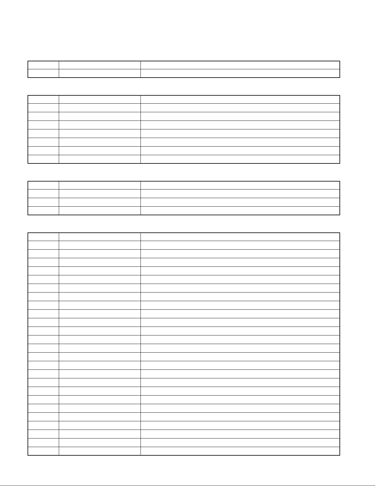
COMPONENTS DESCRIPTION
● SUB-CIRCUIT UNIT (X16-2080-10)
Ref. No. Application/Function Operation/Condition/Compatibility
IC1 E2PROM For security
● SUB-CIRCUIT UNIT (X16-2140-10)
Ref. No. Application/Function Operation/Condition/Compatibility
IC1 LCD driver KEY Input
IC2 LCD driver
IC3 Remote control sensor
Q1 KEY scan start SW ON when the base goes “L”.
Q5, D26 VLCD AVR
Q6
Q11 Dimmer control LCD back light control. OFF when the base goes “L”, ON when the base goes “H”.
● SWITCH UNIT (X16-2190-10)
Ref. No. Application/Function Operation/Condition/Compatibility
Q1 DSI (Disabled System Indicator) DSI blinks when the base goes “H/L”
Q2 KEY illumination SW (GREEN) ON (KEY illumination green) when the base goes “H”
Q3 KEY illumination SW (RED) ON (KEY illumination red) when the base goes “H”
Remote control sensor power supply SW
ON when the base goes “L”.
● ELECTRIC UNIT (X25-966x-xx)
Ref. No. Application/Function Operation/Condition/Compatibility
IC1 System µ-com
IC2 E-vol & N.C. & MPX
IC3 Regulator IC for A8V
IC4 Power IC
IC5 Swiching regulator IC for CD5V
IC7 Reset IC
IC8 Logic IC for muting
IC12 RDS decoder IC
IC13, 14
IC15 ROM IC For ROM correction.
Q1, 2 B.U.5V AVR While BU is applied, BU5V AVR outputs +5V.
Q3 SW5V When Q3’base goes Lo, SW5V outputs +5V.
Q4, 5 SW14V When Q5’base goes Hi, SW14V outputs 14V.
Q6~8 AUDIO 8V AVR When Q6’base goes Hi, A8V AVR outputs 8.4V.
Q9, 34 SERVO+B AVR When Q34’base goes Hi, S+B AVR outputs 7.4V.
Q10 SW for IC5 When Q10’base gose Hi, Q10 is turned on.
Q11~14 ILL+B AVR When Q11’base goes Hi, AVR outputs 10.5V.
Q23, 24 P-ANT SW When Q23’base goes Hi, P-ANT SW outputs 14V.
Q25, 26 P-CON SW When Q26’base goes Hi, P-CON SW outputs 14V.
Q27, 28 P-CON protection Protect Q27 by turning on when P-CON output is grounded.
Q29 Ex Amp control buffer
Q30 Small lamp det SW When Q30’base goes Hi, Q30 is turned on.
Q32 BU det When Q32’base gose Hi, Q32 is turned on.
Q33 ACC det When Q33’base gose Hi, Q33 is turned on.
Q51, 52 Mute driver When a base gose Lo, mute driver is turned on.
Motor driver IC for panel mechanism
4
 Loading...