

Kenwood KDC-3028, KDC-328 Service Manual

CD RECEIVER
KDC-3028
KDC-328
SERVICE MANUAL
© 2005-2 PRINTED IN JAPAN
B53-0246-00 (N) 609
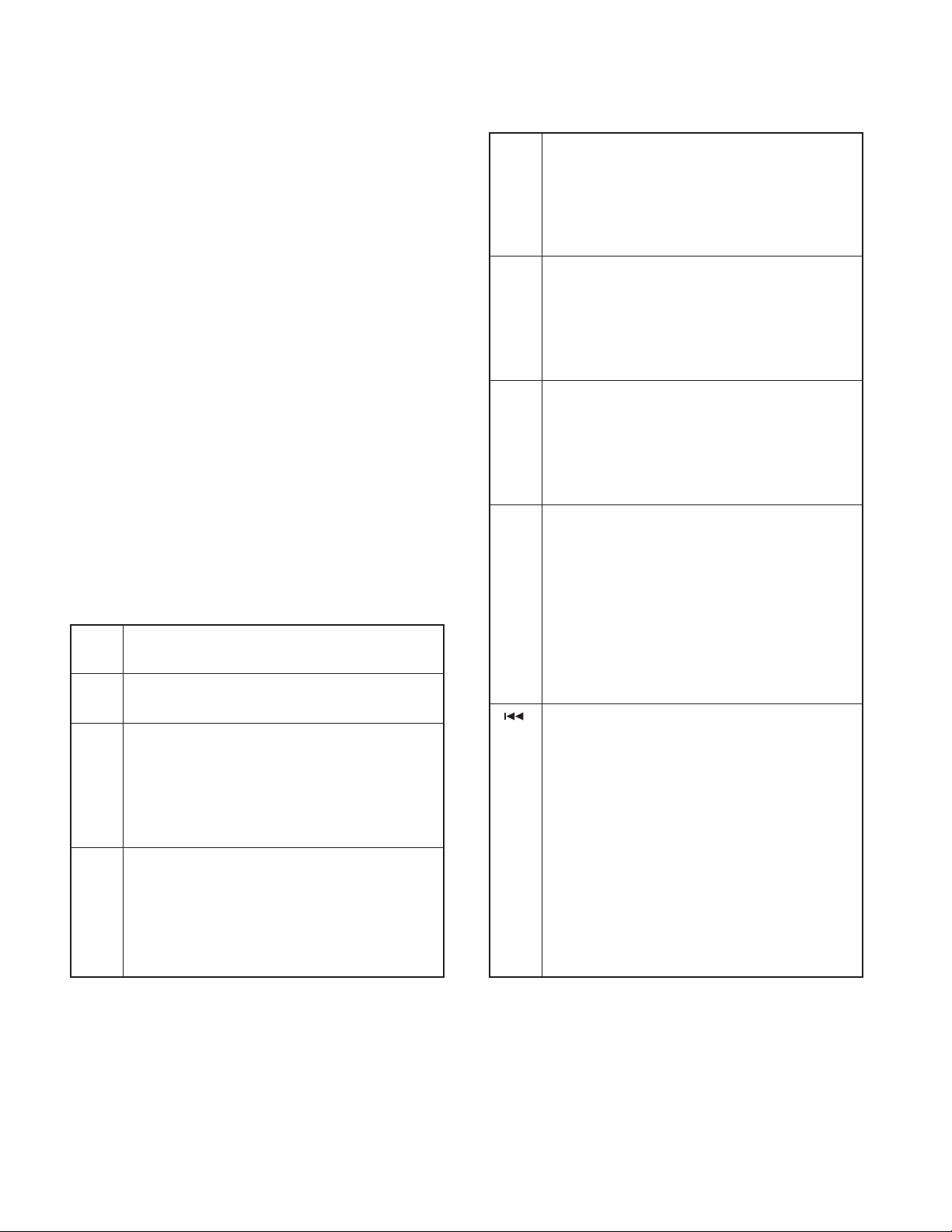
SPARE TDF PANEL
MAIN UNIT NAME TDF PARTS No. TDF NAME
KDC-3028 Y33-2150-68 TDF-53DB
KDC-328 Y33-2150-67 TDF-53D
PANEL ASSY
KDC-3028 (A64-3630-12)
ATT
VOLVOL
AUDAUD
SETSETUPUP
MENUMENU
FFFF
MOUNTING HARDWARE ASSY
(J22-0011-03)
DC CORD
(E30-6415-15)
KDC-
3028
C.S.
DISPDISP
SCAN RDM REP M.RDM
PLASTIC CABINET ASSY
(A02-2743-03)
* ESCUTCHEON
(B07-xxxx-xx)
PANEL ASSY
KDC-328 (A64-3486-12)
SCRL
AUTO
AME
ATT
VOLVOL
AUDAUD
SETSETUPUP
MENUMENU
FFFF
SCAN RDM REP M.RDM
KDC-
SCRL
AUTO
328
C.S.
DISPDISP
AME
REMOTE CONTROLLER ASSY (RC-517)
(A70-2069-05)
BATTERY
(Not supplied)
LEVER
(D10-4589-04) x2
SCREW SET
(N99-1757-05)
SCREW SET
(N99-1763-05)
* Depends on the model. Refer to the parts list.
MOUNTING HARDWARE (L)
(J22-0258-04)
MOUNTING HARDWARE (R)
(J22-0259-04)
This product uses Lead Free solder.
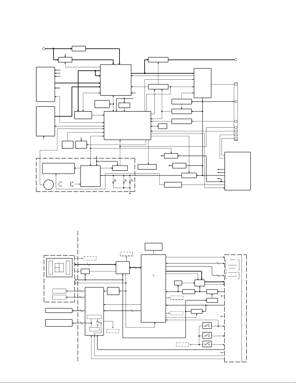
KDC-3028/328
BLOCK DIAGRAM
J4
ANT
Q501
CD or MD
MECHA
AUDIO OUT
J2
CHANGER
AUDIO OUT
BACK
SWITCH UNIT (X16-)
ED1
VFD
S1
VOL
AM+B
AM AGC
SERVO
A8V
BU5V
CD5V
EJECT
KEY
.......
L506
FM AGC
RDS
DECODER
BU5V
Q156S152
EJECT
ILLUMI
800mV
1200mV
PAN5V
IC1
VFD DRIVER
with
KEY MATRIX
IC10
IC11
E2PROM
MPX OUT
MPX IN
IC1IC7
ELECTRIC UNIT (X34-)
E-VOL
&
TUNER
IC8
RST IC
u-COM
IC2
REMOTE
.......
KEY
ILLUMI
A8V
BU5V
S151
PANEL DET
Q351,352
PRE MUTE
IC6
MUTE LOGIC
OEM
PAN5
SERVO
Q51
Q52
Q53
Q151
PAN5V
Q152
ILLUMI SW
SURGE DET
BU DET
ACC DET
Q72,73
SERVO
IC15
VFD REG
IC4
POWER IC
AM+B
A8V
BU5V
:1800mV
FM (J/K)
:
1372mV
FM (E)
AM (J/K)
:
AM (E)::
IC3
POWER SUPPLY IC
600mV
855mV
P-CON
P-ANT
AM+B
AUDIO+B
VCC
BU5V
ILLUMI
J6
PRE OUT
CD/MD
CHANGER
J1
SP OUT
BACK UP
ACC
OEM REMOTE
TEL MUTE
P-ANT
P-CON
3600mV
3600mV
:
MECHA ASSY (X92-)
CD PLAYER UNIT (X32-5750-00)
X1
CLOCK
PICK-UP (DPU1)
A
EF
C
B
TR COIL
FO COIL
DM1
SPINDLE MOTOR
DM2
LOADING & SLED
MOTOR
Q1
2
2
2
2
D. GND
APC
IC3
7
VREF
MOTOR
DRIVER
LOADING
H
L
SLED
Q5,6,D3
CURR.
AMP
S. GND
IC1
RF AMP
D. GND
VREF
4
12
16.934MHz
IC2
SERVO
PROCESSOR
u-COM
DRV MUTEMUTE
VREF
A+5V
A. GND
D. GND
REF
SW +5V
D. GND
D2
5V REG
IC4
LPF
Q4
8V SW
Q3
SW
Q2
5V SW
4
2
S3
S2
S1
MOTHER
BOARD (X34-)
DOUT
CLK
DATA
MSTOP
MRST
MUTE L
MUTE R
L-ch
R-ch
A8V
A. GND
BU5V
D. GND
LOE/LIM SW
12EJE SW
LOS SW
S7.5V
S. GND
MOTOR
LO/EJ
22
19
18
10
11
12
13
8
6
9
7
15
14
1
21
20
3
2
4
5
2

KDC-3028/328
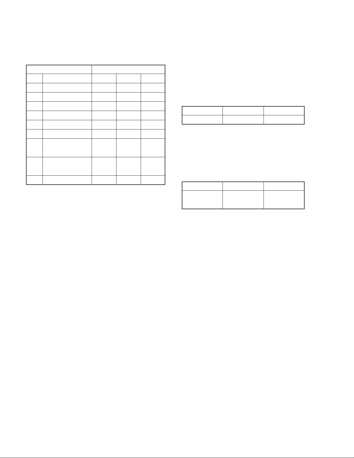
COMPONENTS DESCRIPTION
● ELECTRIC UNIT (X34-3390-1x)
Ref. No. Application / Function Operation / Condition
IC1 SYSTEM µ-COM System control.
IC3 POWER SUPPLY DC5V x 1, 7.8V x 1, 8.0V x 1, 10.2V, P-CON, P-ANT output.
IC4 POWER IC Signal amplifier.
IC6 MUTE LOGIC Mute action control.
IC8 RESET IC “L” when detection voltage is below 3.6V.
IC10 E-VOL & TUNER E-vol, tuner, stereo decode.
IC11 E2PROM Save & load for tuner adjustment data.
IC15 LED & VFD+B Output voltage 11.25V for LED and VFD.
Q51 SERGE DET “ON” when the base goes “H”.
Q52 BU DET “ON” when the base goes “H” during BU is applied.
Q53 ACC DET “ON” when the base goes “H” during ACC is applied.
Q54 BU5V SW “ON” when the base goes “L”.
Q71 SERVO+B CONTROL SW “ON” when the base goes “H”.
Q72 SERVO+B AVR Output voltage is 7.5V.
Q73 SERVO+B AVR Output voltage is 7.5V.
Q74 IC3 CONTROL SW “ON” when the base goes “H”. Output voltage is 10.2V.
Q151 PANEL 5V SW “ON” when the base goes “L”.
Q152 FL+B SW “ON” when the base goes “L”.
Q153 FL+B SW “ON” when the base goes “H”.
Q156 EJECT ILLUMI SW “ON” when the base goes “H”.
Q252 IC4 STBY SW “ON” when the base goes “L”.
Q330 Q351/Q352 MUTE DRIVER “ON” when the base goes “L”.
Q351 Lch PREOUT MUTE SW Audio preout is muted when the base goes “H”.
Q352 Rch PREOUT MUTE SW Audio preout is muted when the base goes “H”.
Q501 AM RF AMPLIFIER Adjusts for Gain.
● CD PLAYER UNIT (X32-5750-00)
Ref. No. Application / Function Operation / Condition
Generation of RF signal based on the signals from the APC circuit and pickup, and
IC1
IC2
IC3 4ch BTL DRIVER
RF AMPLIFIER responding generation of servo error (focusing error and tracking error) signals.
to CD-RW Detection of dropout, anti-shock, track crossing and off-tracking conditions, included
gain control function during CD-RW.
Focusing, tracking, sled and spindle servo processing.
CD SIGNAL PROCESSOR Automatic adjustment (focusing, tracking, gain, offset and balance) operations.
built-in µ-COM Digital signal processing (DSP, PLL, sub-codes, CIRC error correction, audio data
interpolation processing) operations, and microcomputer function.
Focusing coil, tracking coil, spindle motor and sled motor driver, disc loading and
eject operation.
3
KDC-3028/328
COMPONENTS DESCRIPTION
Ref. No. Application / Function Operation / Condition
IC4 L.P.F. (LOW PASS FILTER) 2nd low pass filter for audio signals.
Q1
Q2 DIGITAL +5V SW “ON” When P. ON signal goes “L”.
Q3 Q4 SW “ON” When P. ON signal goes “L” (SW+5V is ON).
Q4 ANALOG +8V SW “ON” When P. ON signal goes “L” (Q3 is ON).
Q5, 6 CURRENT AMP Current driver.
● SWITCH UNIT (X16-2910-11)
Ref. No. Application / Function Operation / Condition
IC1 VFD DRIVER
IC2 REMOTE CONTROL
Q4 SW 5V The power supply of IC2 turns on when Q4’s base goes “L”.
Q10 RED LED SW RED LED turns on when Q10’s base goes “H”.
APC (AUTOMATIC POWER CONTROL)
LD power control.
● DAUGHTER UNIT (X89-2690-10)
Ref. No. Application / Function Operation / Condition
Q221, 222 2-PREOUT MUTE “ON” when the base goes “H”.
Q225 2-PREOUT MUTE “ON” when the base goes “H”.
4
KDC-3028/328
MICROCOMPUTER’S TERMINAL DESCRIPTION
● SYSTEM µ-COM : IC1 on X34- (ELECTRIC UNIT)
Pin No. Pin Name I/O Application Processing Operation
1 DCERR I DC offset detection input
2 LINE MUTE I Phone detection TEL MUTE : Below 1V
3ROTARY CW I Rotary encoder input
4AVSS 5 TUN TYPE1 I E-VOL setting switch Refer to “TUN TYPE” on the TRUTH TABLE
6 TUN TYPE2 I E-VOL setting switch Refer to “TUN TYPE” on the TRUTH TABLE
7AVREF1 8 VFD DATAF I Data input from FVD driver
9 VFD DATAS O Data output to FVD driver
10 VFD CLK O Clock output to FVD driver
11 VFD RST O Reset output to FVD driver
12 VFD CE O Chip enable output to VFD driver
13 ROTARY CCW I Rotary encoder input
14 FLIP DET I Panel detection Panel released : H, Panel ON : L
15 PWIC BEEP O Beep output
16 LX DATA S I Data from slave unit
17 LX DATA M O Data to slave unit
18 LX CLK I/O LX-BUS clock
19 NC -
20 TUN ADJ I For adjusting IC10
21 TUN SD I Tuner search stop input H : Station exists, L : Station does not exist
22 LX RST O Hard reset to slave unit H : Reset, L : Normal condition
23 LX CON O Start-up request to slave unit H : Slave unit ON, L : Slave unit OFF
24 LX REQ M O Communication request to slave unit
25 AUD SDA I/O Tuner + volume I2C data input and output
26 AUD SCL I/O Tuner + volume I2C clock input and output
27 PWIC STBY O Power IC standby output Power IC ON : H, Power IC OFF : L
28 VOL MUTE O E-VOL mute output L : Mute OFF, Hi-Z : Mute ON
29 PWIC MUTE O Power IC mute output Power OFF : L, Standby : L, Tel mute : L
30 RDS AFSM 31 RESET2 O Mute for reset Output L
32 NC 33 VSS1 34 NC 35 ACC DET I ACC detection ACC exists : L, ACC does not exist : H
36 BU DET I Momentary power-down detection BU exists : L, BU does not exist (Momentary power-down) : H
37 PON I/O SW5V/SW14V control Power ON : L, Power OFF : Hi-Z
38,39 PS2-2, PS2-1 O Power supply control output Refer to “POWER IC CONTROL” on the TRUTH TABLE
Display OFF, Key reset, Panel opened : L
Display ON, Key scan : H
Adjustment=H, PS1-1, 2=L, PS1-3=Hi-Z, PS2-1, 2=Hi-Z
TUN DATA, CLK=Hi-Z
5

KDC-3028/328
MICROCOMPUTER’S TERMINAL DESCRIPTION
Pin No. Pin Name I/O Application Processing Operation
40~42 PS1-1~PS1-3 O Power supply control output Refer to “POWER IC CONTROL” on the TRUTH TABLE
43 KEY CDEJ I Eject key L : Eject
44 PON CD I/O Power supply control for MP3/WMA ON : L, OFF : Hi-Z
45 CD MUTE I CD mute request L : Mute request
46 CD MSTOP O CD mecha µ-com stop H : mecha µ-com operates, L : mecha µ-com is stopped
47
48 CD LOEJ I/O CD motor control
49 CD MOTOR O CD motor control
50 CD DISC8 SW 51 CD MRST O CD mecha µ-com reset H : Normal condition, L : Reset
52 CD SCL I/O CD mecha I2C clock output
53 CD DISC12 SW I 12cm CD detection
54 CD LOS SW I CD loading detection
55 CD SDA I/O CD mecha I2C data input and output
56 OEM DISP CE I/O External display chip enable External display
57 OEM DISP CLK I/O External display clock External display
58
59 EJECT ILLUMI O Eject illumination control LED ON when FLIP-DOWN DET is H and PANEL DET is L.
60 RESET I
61 PANEL DET I Panel detection Panel OFF : L, Panel ON : H
62 PON FL O VFD power supply ON
63 KEY REQ I Communication request from VFD driver L : Key input
64 NC 65 REMOTE I Remote control input
66 LX REQ S I Communication request from slave unit
67 VSS0 68 VDD1 69,70 X2, X1 71 TEST 72,73 XT2, XT1 74 VDD0 75 AVDD 76~78
79 NC 80 TUN SMETER I Tuner S-meter input
CD LOE LIM SW
OEM DISP DATA
TYPE 3~TYPE 1
I CD detection (chucking switch) H : Loading is finished, L : Disc does not exist
Refer to “CD MECHA CONTROL OPERATION” on the
TRUTH TABLE
Refer to “CD MECHA CONTROL OPERATION” on the
TRUTH TABLE
I/O External display chip data External display
LED ON : H, LED OFF : L
LED blinks when FLIP-DOWN DET is H and PANEL DET is L.
VFD ON : H, VFD OFF : L
Flip-down detection H : L, Flip-down detection L : H
I Destination switch
6

MICROCOMPUTER’S TERMINAL DESCRIPTION
● TRUTH T ABLE
TUN TYPE
General models commercially-designated as pure KENWOOD brand (Initial value)
Initial value setting
General models commercially-designated as pure KENWOOD brand (CRSC is changed)
Multi-Path Band-Path Gain = 12dB, Multi-Path Charge Current = 0.4µA, De-Emphasis = 75µS
POWER SUPPLY IC (IC3) CONTROL
SW1 (Pin No. 10)
PS1-1 PS1-2 PS1-3 AUDIO P-CON P-ANT
LLLOFFOFF OFF
HLLONOFF OFF
HHLONONOFF
HHHONONON
KDC-3028/328
TYPE 1 TYPE 2
LL
HL
SW2 (Pin No. 11)
PS2-1 PS2-2 ILLUMI FM+B AM+B
LLOFF OFF OFF
HLONON OFF
HHONON ON
CD MECHA CONTROL OPERATION
CD LOEJ CD MOTOR CD MECHA OPERATION
LH Load
HH Eject
Hi-Z L Stop
Hi-Z H Brake
7

KDC-3028/328
MICROCOMPUTER’S TERMINAL DESCRIPTION
● CD MECHANISM µ-COM : IC2 on X32- (CD PLAYER UNIT)
Pin No. Pin Name I/O Application Processing Operation
1 TVD O Traverse drive output (PWM output).
2 SPL O Spindle motor drive output (PWM output).
3NC-No connection.
4 PWM O Multipurpose PWM output.
5 TBAL O Tracking balance adjustment output (PWM output).
6 FBAL O Focusing balance adjustment output (PWM output).
7 NRFDET I RF detection signal input. L : Detection
8 OFT I Off-tracking signal input. H : Detection
9 BDO I Drop-out signal input. H : Detection
10 LDON O Laser-on signal output. H : Focus ON
11 DSLB O DSL balance output.
12 DVDD1 - Power supply for digital circuit.
13 DVSS1 - GND for digital circuit.
14 AVSS2 - GND for analog circuit. For DSL, PLL and A/D converter
15 DSLF I/O Loup filter for DSL and bias output for ARF.
16 ARF I RF signal input.
17 RFSW I DSL circuit time constant switch.
18 PLLF I/O Loup filter for PLL.
19 PLLF2 I/O Loup filter character switch for PLL.
20 IREF I Reference current input.
21 RFENV I RF envelope signal input.
22 TRCRS I Tracking cross signal input.
23 TE I Tracking error signal input.
24 FE I Focusing error signal input.
25 AVDD2 - Power supply for analog circuit. For DSL, PLL and A/D converter
26 AVSS1 - GND for analog circuit. For Lch/Rch audio output
27 OUTR O Rch audio output.
28 AVDD1 - Power supply for analog circuit. For Lch/Rch audio output
29 OUTL O Lch audio output.
30 DVSS3 - GND for digital circuit.
31 CSEL 32 NC - No connection.
33 ASEL 34 MSEL0 35 MSEL1 36~39 NC - No connection.
40 VREFP - Reference power supply input for A/D converter.
41 HOT -
8
KDC-3028/328
MICROCOMPUTER’S TERMINAL DESCRIPTION
Pin No. Pin Name I/O Application Processing Operation
42 8EJE SW 43
44 LOE/LIM SW I
45~49 NC - No connection.
50 DVDD2 - Power supply for digital circuit.
51 X1 I Main clock input.
52 X2 O Main clock output.
53 DVSS2 - GND for digital circuit.
54 XSUB1 55 NC - No connection.
56 TEST1 - Test terminal. Normal condition : “H” fixed
57 TEST2 - Test terminal. Normal condition : “H” fixed
58,59 NC - No connection.
60 DRV MUTE O Driver mute control. L : Mute ON, H : Mute OFF
61 MUTE L O Audio Lch mute output.
62 MUTE R O Audio Rch mute output.
63 RST I LSI reset input.
64 OCD CLK 65 MSTOP I Standby detection.
66 DATA I/O
67 SBIO I Data input. During serial writer is connected.
68 CLK I/O
69 TX O Digital audio interface signal output.
70 NC - No connection.
71 XSEL 72 MCNT I Loading control / Eject control. L : OFF (Host control), H : Mecha µ-com control
73 P. ON O Audio & Servo power supply control. L : Power supply ON. H : Power supply OFF
74,75 NC - No connection.
76 CD-RW O CD-RW control. H : CD-RW, L : Normal disc
77 NC - No connection.
78 DVDD3 - Power supply for digital circuit.
79 FOD O Focusing drive output (PWM output).
80 TRD O Tracking drive output (PWM output).
12EJE/SDET SW
Loading-end detection / H : Loading-end detection
Pick-up inner circumference detection. L : Pick-up inner circumference detection
I2C bus data line (Communication line to system µ-com).
I2C bus clock line (Communication line to system µ-com).
During serial writer is connected.
During serial writer is connected.
9
KDC-3028/328
TEST MODE
How to enter the test mode
While simultaneously press PRESET “1” k e y and PRESET “3”
key, press “RESET” button.
How to release the test mode
Press “RESET” button. (The release cannot be achieved in
the conditions of POWER OFF and ACC OFF.)
Initial conditions of the test mode
• The source is “STANDBY”.
• The displays all lit up.
• The volume is at –10dB (The display shows “30”.)
• LOUD is “OFF”.
• CRSC is “OFF”.
• SYSTEM Q is “NATURAL”.
• BEEP is sounded at all time with the key depressed f or less
than 1 second.
Special displays when all indicator lights are lighted
When “PRESET” keys are pressed while all indicators for the
STANDBY sources are lighted, the following displays will appear.
PRESET
“1” key (Display) : x x x x x x x x
PRESET
“2” key (Display) : x x x x x x x x
PRESET
“3” key time display (STANDBY source time is not counted.)
PRESET
“4” key time display
•Version display (8 digits : month, date, hour, minute)
• Serial number display (8 digits)
•When pressed for less than 1 second : POWER ON
(Display) : PON x x x x x MAX 60,000 (hours)
* The display is cleared by pressing the key for more
than 2 seconds.
• When pressed for less than 1 second : CD operation
(Display) : PLY x x x x x MAX 60,000 (hours)
* The display is cleared by pressing the key for more
than 2 seconds.
PRESET
“5” key number display
PRESET
“6” key close number display
•When pressed for less than 1 second : CD EJECT
(Display) : EJC x x x x x MAX 60,000 (times)
* The display is cleared by pressing the key for more
than 2 seconds.
• When pressed for less than 1 second : Panel open/
(Display) : PNL x x x x x MAX 600,000 (times)
* The display is cleared by pressing the key for more
than 2 seconds.
“FM” • ROM CORRECTION version display
key (Display)
Effective : ROM _ Rxxx (x : number)
Not effective (When not able to read)
Not effective (When version is different)
“AM” • IC10 adjustment status (Refer to “ADJUSTMENT” on
key the following page.)
(Display)
Adjustment complete : E2P _ OK _ _
Adjustment not completed : E2P _ ER _ _
Communication error : I2C _ ER _ _
* When other than “E2P _ OK _ _” , Pin No. 30 will
become “H”.
“ ”•Mechanism error detection status
key•Communication error → Error No. 1 → Error No. 2 →
Error No. 3 → Communication error (Error No. 1 is the
most recent error.)
(Display)
Communication OK : I2C _ OK _ _
Communication error : I2C _ NG _ _
Not detected : ERR _ n – – – (n : 1~3)
Detected : ERR _ n-✳✳ (✳✳ : error code)
* The display is cleared by pressing the key for more
than 2 seconds.
: ROM _ R – – –
: ROM _ R✳✳✳
10

KDC-3028/328
SPECIAL MODE
● Security
•
How to enter the forced POWER ON mode
While “– – – –” is being displayed, while simultaneously
pressing “Q” key and “4” key, press “RESET” button, With
this, it is possible to turn the power on for 30 minutes only.
• How to clear the programmable security code
1. While “– – – –” is being displayed, press “ ” for 3 seconds
or more while pressing the “A UTO” key. This makes the “– –
– –” display disappear.
2. Input “KCAR”, using the remote controller.
Press “5” key of the remote controller twice (Input for “K”)
and press “
Press “2” k e y of the remote controller 3 times (Input for “C”)
and press “ ” key.
Press “2” key of the remote controller once (Input for “A”)
and press “ ” key.
Press “7” key of the remote controller twice (Input for “R”)
and press “ ” key.
3. The security is cleared and the unit enters ST ANDBY source
mode.
4. If wrong codes are input, “– – – –” will be displayed again.
” key.
● DC offset error detection confirmation mode
Confirmation mode :
While depressing PRESET “3” key and PRESET “6” key
simultaneously, press on the “RESET” button.
(Display) Detected : DC _ ERR _ _
Not detected : DC _ OK _ _ _
* By pressing “AUTO” or “TI” key while “DC _ ERR _ _” is
being displayed, detection status is cleared. This will result
in the display of “DC _ OK _ _ _”.
Release Method : Press “RESET” button.
● Mechanism memory clear confirmation mode
Confirmation mode :
While depressing “ATT” key and “Q” key simultaneously,
press “RESET” button.
(Display) : MEM _ CLR _
*Two seconds after the confirmation mode boots up, Mecha-
nism memory clear as a result is displayed.
(Display) Clear status display normal completion
: CD _ O _ _ _
Clear status display abnormal completion
: CD _ X _ _ _
Release Method : Press “RESET” button.
● FM/AM channel space switching
When in the conditions of ACC ON and POWER OFF, while
depressing PRESET “1” key and PRESET “5” key simultaneously, press “SRC” key.
11
KDC-3028/328
ADJUSTMENT
After replacing the following parts, adjust as follows.
REPLACED PARTS ADJUSTMENT ITEMS
Ref. No.
Function / Parts name
IC10 E-VOL & TUNER YES YES YES
IC11 E2PROM YES YES YES
L507 VCO COIL YES YES YES
L508 1st AM MIX IFT YES - L509 2nd AM MIX IFT - YES L518 FM ANTENNA COIL - - YES
D504 VARIABLE YES YES YES
CAPACITANCE DIODE
D506 VARIABLE YES YES YES
CAPACITANCE DIODE
X501
CRYSTAL RESONATOR
1st AM MIX 2nd AM MIX FM antenna
YES YES YES
● 1st AM MIX / 2nd AM MIX ADJUSTMENT
ADJUSTMENT POINT : L508 (1st AM MIX) / L509 (2nd AM
MIX)
VOLTAGE VALUE CHECK POINT : S-METER check land (X34-)
Adjust so that S-METER voltage value becomes maximum.
• SG setting
FREQUENCY MODULATION ANTENNA INPUT
1000kHz OFF 35dBµV (EMF)
● FM ANTENNA ADJUSTMENT
ADJUSTMENT POINT : L518
VOLTAGE VALUE CHECK POINT : S-METER check land (X34-)
Adjust so that S-METER voltage value becomes maximum.
• SG setting
FREQUENCY MODULATION ANTENNA INPUT
5dBµV (LOAD) or
87.9MHz OFF
11dBµV (EMF)
12
 Loading...