

Page 1
CD RECEIVER
KDC-3025/325/5026/G
SERVICE MANUAL
© 2003-11 PRINTED IN JAPAN
B53-0106-00 (N) 1029
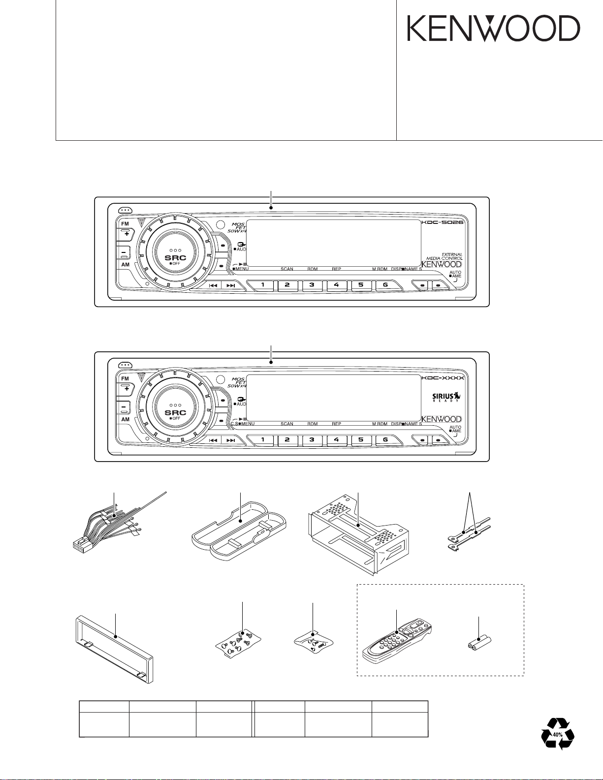
KDC-5026/5026G
KDC-3025
KDC-325
Panel assy
(A64-3190-02):KDC-5026G
(A64-3191-02):KDC-5026
Panel assy
(A64-3183-02):KDC-325
(A64-3185-02):KDC-3025
CD MECHANISM EXTENSION CORD : W05-0618-00
DC cord
(E30-6322-05)
Escutcheon
(B07-3083-02):KDC-5026G
(B07-3098-02):KDC-325/5026
(B07-3100-02):KDC-3025
TDF PANEL INFORMATION
MODEL TDF PANEL No. TDF NAME
KDC-325 Y33-1930-60 TDF-43D
KRC-3025 Y33-1930-61 TDF-43DB
Plastic cabinet assy
(A02-1486-13)
Screw set
(N99-1719-05)
Mounting hardware assy
(J22-0011-03)
Screw set
(N99-1730-15)
MODEL TDF PANEL No. TDF NAME
KDC-5026 Y33-1930-63 TDF-5026
KRC-5026G Y33-1930-62 TDF-5026G
Remote controller assy (RC-505)
(A70-2040-05)
Except KDC-5026G
Lever
(D10-4589-04)
SIZE AA BATTERY
x2
Page 2
2
Q201
BUFFER
IC1
IC2
REMOCON
RESET SW
ENCODER
ROTARY
S1
WITH
LCD DRIVER
KEY MATRIX
IC1
LCD
PANEL DET
S1
EJECT SW
S1
EJECT ILLUMI
DSI
u-COM
IC2
MPX
E-VOL
&
ACC DET
TEL MUTE
B.U DET
PRE MUTE
DRIVER
MUTE
IC6
POWER
IC
IC4
THERMAL
PROTECT
ACC
TEL MUTE
BACK UP
(REAR)
PRE OUT
(FRONT)
PRE OUT
SP OUT
SURGE DET
SERVOSERVO+B
SW 14V
Q21
WIRED REMO
SUPPLY
IC
IC3
POWER
ANT CON
P CON
RESET
IC8
SW 5V
Q4
PANEL 5V
Q152
SW5V
ILLUMI CON
DRIVER
MUTE
PRE MUTE
KDC-3025 only
S-METER
AUDIO OUT
IFC OUT
PLL-DATA
PLL-CLK
SW5V
AM+B
A8V
LOE/LIM SW
12EJE SW
LOS SW
MS CLK
MS DATA
M MUTE
LO/EJ
M STOP
MOSW
M RST
SERVO+B
A8V
BU5V
LX-DATA C
LX-MUTE
LX-REQ H
LX-REQ C
LX-CLK
LX-CON
LX-DATA H
BACK UP
NOISE
S-METER
FM
AM
MP IN
LEVEL
CD
QUAL
AFS
CH
BU5V
PANEL DET
EJECT
DSI
L CLK
L DATAS
L CE
L DATAL
VOLUME A
VOLUME B
REMO
ILL CON
MUTE
P-MUTE
PHONE
ACC DET
B.U DET
BEEP
PS1-0
PS1-1
PS1-2
PS2-0
PS2-2
RST
BU5V
BACK UP
A8V
SW5V
BACK UP
AM+B
ILLUMI
A8V
BU5V
BU5V
BU5V
MODE
CD
FM
AM
CH
LEVEL
3600mV
1800mV
600mV
3600mV
LX-RST
REAR
FRONT
TUNER
CD
CH
SWITCH UNIT (X16- )
DAUGHTER UNIT
(X89- )
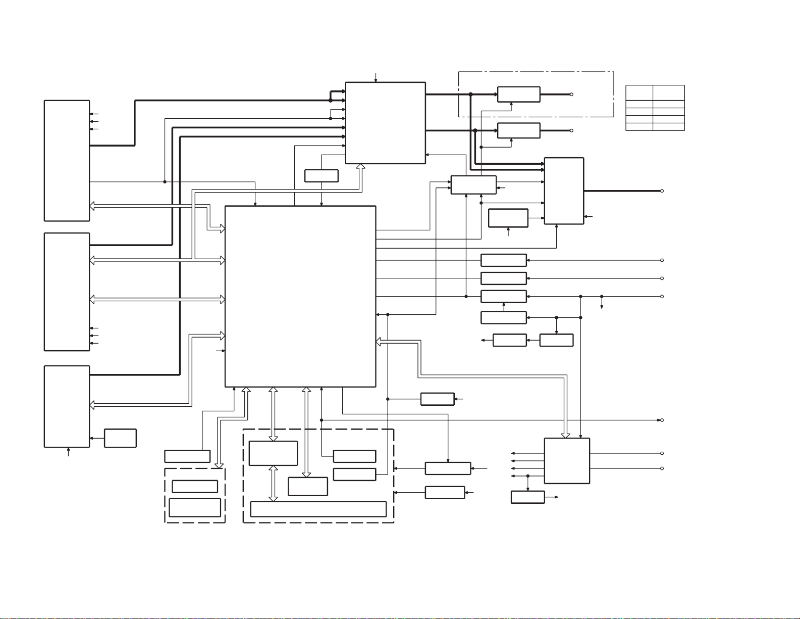
KDC-3025/325/5026/G
BLOCK DIAGRAM
Page 3
KDC-3025/325/5026/G
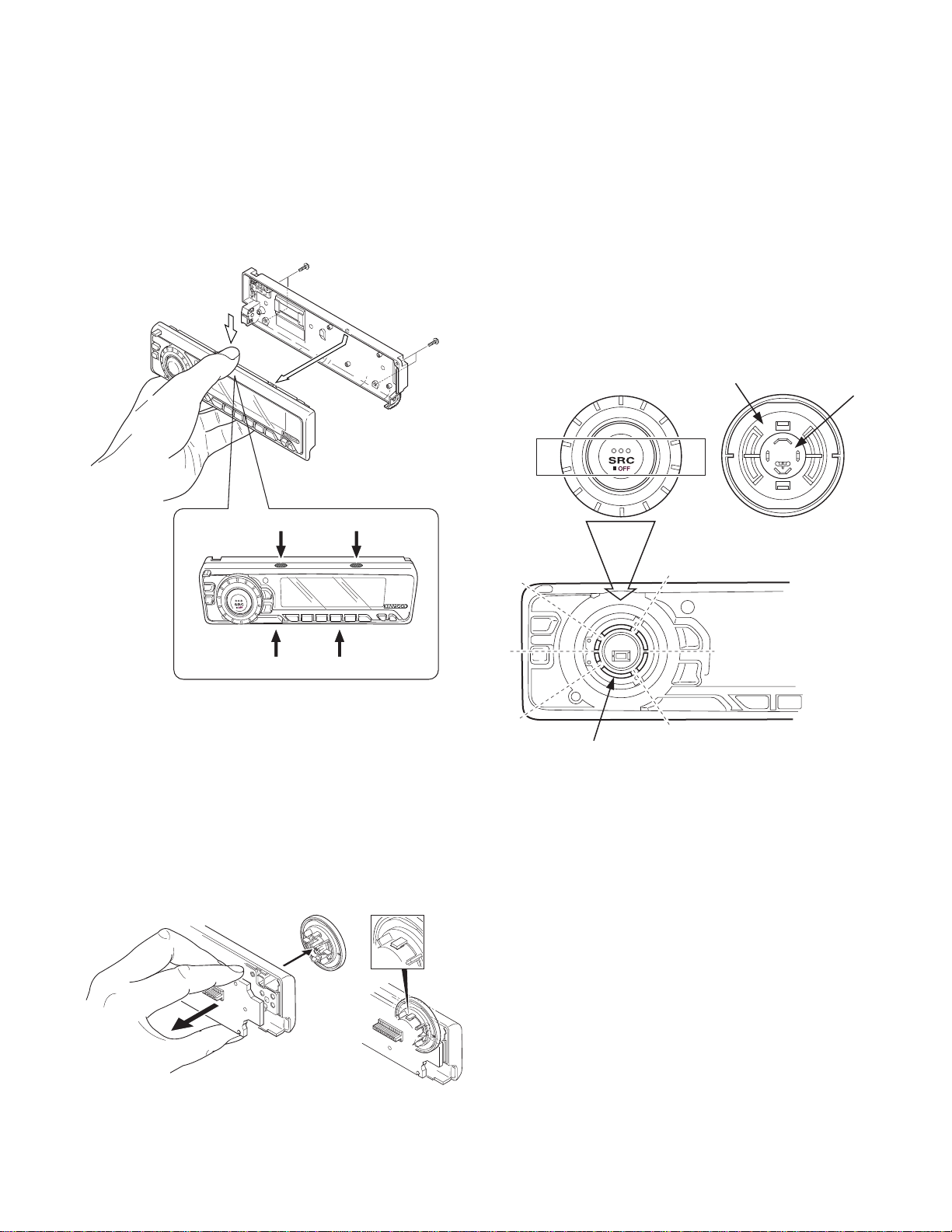
DISASSEMBLY FOR REPAIR
How to Disassemble (PANEL ASSY)
1)Remove four screws (A).
2)While holding the section (B) indicated with arrows, pull and
remove PANEL ASSY.
x2
A
A
B
B
How to install knob (SRC)
1)Place knob (F) and knob (G) in the positions indicated in
the diagram below.
2)While keeping these positions, use a piece of adhesive tape
(H) to hold knobs in position, as shown in the diagarma.
3)Set the rotary (J) position as shown in the diagram.
4) While keeping the letters “SRC” horiz ontally in position, set
it to the rotary on the panel.
5)Remove the adhesive tape (H).
x2
F
G
H
B
3) Pull SWITCH UNIT (C) as indicated in the diagram and remove knob (D).
(The knob (D) is attached to the rotary with hook (E) and it
is not possible to remove hook (D) only.)
C
B
D
E
J
3
Page 4
KDC-3025/325/5026/G
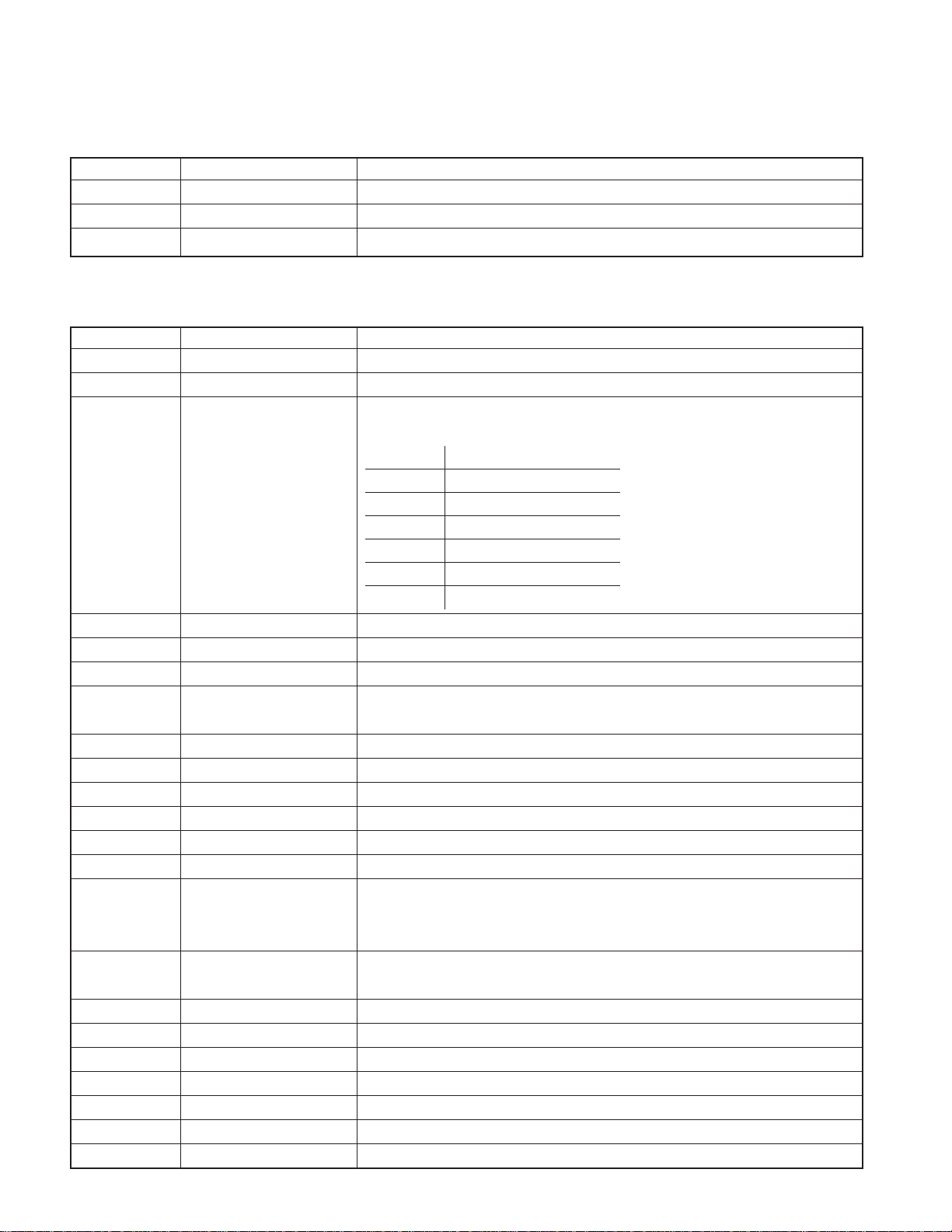
COMPONENTS DESCRIPTION
● SWITCH UNIT (X16-2500-xx)
Ref. No. Application/Function Operation/Condition/Compatibility
IC1 LCD Driver Drives LCD
IC2 Remote Control IC Controls the unit.
Q1,Q4 REMO ON SW The power supply of IC2 is turned on when base level goes “L”.
● ELECTRIC UNIT (X34-3090-xx)
Ref. No. Application/Function Operation/Condition/Compatibility
IC1 System µ-COM Controls FM/AM tuner, the changer, CD mechanism, Panel, volume, and tone.
IC2 E.Vol & N.C.MPX Controls the source, volume, tone and FM multiplex detector.
Bu5V (5V) Audio8V (8V) FM+B (8V)
AM+B (8V) P-CON ANT-CON
SW1 OUT
1.5~3.0 Audio ON
IC3 Power Supply IC
3.5~5.0 Audio P-CON ON
7.0~ Audio P-CON P-ANT ON
SW2
2.0~3.0 ILLUMI FM ON
4.0~ ILLUMI AM ON
IC4 Power IC Amplifies the front L/R and the rear L/R to 50W maximum.
IC6 Muting logic IC Controls logic for muting.
IC8 Reset IC “L” when detection voltage goes below 3.5V or less.
Q1 Surge Detection
Q2 BACK-UP Detection “L” when B.u is present. “H” when B.u is absent or momentary power down is detected.
Q3 ACC Detection “L” when Acc is present.
Q4 SW 5V ON when the base is “L”.
Q21 Servo Regurator
Q22 Servo SW
Q23 Conrtol Power Supply IC
Q151 DSI Driver DSI turns off when the base is “H”.
Q152 Panel 5V SW
Q153,Q154 ILLUMI Control ILLUMI lights when the base of Q153 is “H”.
Q201 Noise buffer
Q351 Pre Mute SW Mutes the Rear Lch when the base is “H”.
Q352 Pre Mute SW Mutes the Rear Rch when the base is “H”.
Q354 Pre Mute SW Drives the Pre Mute sw (Q351, 352, 355, 356) when the base is “L”.
Q355 Pre Mute SW Mutes the Front Lch when the base is “H”.
Q356 Pre Mute SW Mutes the Front Rch when the base is “H”.
“L” when the back-up voltage becomes more than 24V (momentary power down).
“H” when the back-up voltage becomes less than 24V.
DSI lights when the base is “L”.
DSI turns on and off when panel is taken off.
When the panel is attached, the base goes “L”, turning the Tr ON to supply 5V to the panel.
When panel is taken off, panel 5Vcut off.
4
Page 5

KDC-3025/325/5026/G
MICROCOMPUTER’S TERMINAL DESCRIPTION
● SYSTEM MICROCOMPUTER : M30302MC-1N4FP (X34 : IC1)
Pin No. Pin Name I/O Application
1~5 N.C O OPEN (Output L fixed)
6 REMO I Remote control input
7 N.C O OPEN (Output L fixed)
8 BYTE I External data bus width switching input Connect to GND
9 CNVSS I Pull down at 1kΩ
10 XCIN I Sub clock input
11 XCOUT O Sub clock output
12 RESET I Reset input Normal : H, When RESET : L
13 XOUT O Main clock output
14 VSS - GND
15 XIN I Main clock input
16 VCC - Power supply input (5V)
17 NMI Pull up (B.U5V)
18 EJECT I EJECT detection input L : EJECT
19 N.C O OPEN (Output L fixed) (Other than RDS model)
20 LX-REQ S I Reception request from external slave L : Request
21 ILL CON O Illumination output control FLIP DET “L” during “H”
22 PANEL 5V I/O Panel 5V control
23 VOL A I VOL key input
24 VOL B I VOL key input
25
LOE/LIM SW (SW3)
26 BEEP O BEEP output
27 M STOP O STOP request to CD mechanism When CD : H, When STOP : L
28 MOSW O CD mechanism MOTOR SW LOADING, EJECT, Brake : H
29 PLL-CLK I/O Clock output to F/E
30 PLL-DATA I/O Data input/output with F/E
31 LX-DATA M O Data output to external slave Last retention
32 LX-DATA S I Data input from external slave
33 LX-CLK I/O Clock input and output of external slave
34 LX-REQ M O Transmission request to external slave At request : L
35 L DATAS O Data output to LCD driver
36 L DATAL I Data input from LCD driver
37 L CLK I/O Clock output to LCD driver
38 FLIP-DET I Panel collapse detection L : Panel received, H : Panel collapse
39 L CE O CE output to LCD driver
40 LO/EJ I/O CD mechanism LOADING, EJECT switching
41 EPM I For flush writing Pull down at 100kΩ
I CD DOWN SW detection H : Chucking
Truth Value
Table
Processing Operation Description
L : ON (Panel detect & ACC ON)
Hi-Z : OFF (Panel no detect or ACC OFF)
STOP, Brake : Hi-z
LOADING : L, EJECT : H
5
Page 6

KDC-3025/325/5026/G
MICROCOMPUTER’S TERMINAL DESCRIPTION
Pin No. Pin Name I/O Application
42 M RST O RESET output to CD mechanism Normal : H, When RESET : L
43 M-MUTE R I MUTE request (Rch) from CD mechanism L : MUTE ON
44 12EJE SW (SW2) I 12cm DISC detection input L : 12cm disk
45 M-MUTE L I MUTE request (Lch) from CD mechanism L : MUTE ON
46 LX-CON O External slave selection ON : H, OFF : L
47 LO.S SW (SW1) I LOADING SW detection input L : LOADING START
48 DSI O EJECT key, DSI, guide ILLUMI output ILLUMI ON : L, ILLUMI OFF : H
49 PANEL-DET I Detection for panel or no panel H : Panel detect, L : Panel no detect
50 N.C O OPEN (Output L fixed)
51 IFC OUT I F/E IFC OUT input H : Station detect
52,53 N.C O OPEN (Output L fixed) (Other than RDS model)
54 N.C OPEN (Output L fixed)
55 AFS O Constant switch terminal at noise detection
56 SDA I/O Data input/output to IC2, CD mechanism
57 SCL I/O CLK output to IC2, CD mechanism
58 MUTE O IC2 MUTE control MUTE ON : H, MUTE OFF : L
59 N.C OPEN (Output L fixed)
60 IC2 TYPE 0 I
61 IC2 TYPE 1 I
62 VCC Power supply input (5V)
63 N.C O OPEN (Output L fixed)
64 VSS GND
65~67 TYPE 0~TYPE 2 I Destination switching port e
68 N.C O OPEN (Output L fixed)
69 SVR O Power IC SVR control Momentary power dropped : H
70 P-STBY O Power IC STBY control
71 P-MUTE O Power IC MUTE control
72 SW5V I/O SW5V control ON : L, OFF : Hi-z
73 B.U-DET I Momentary power dropped detection input L : B.U detect, H : B.U no detect
74 ACC-DET I Acc detection input L : Acc detect, H : Acc no detect
75 N.C O OPEN (Output L fixed)
76~78 PS1-0~PS1-2 O Power supply IC control terminal q
79,80 PS2-0~PS2-1 O Power supply IC control terminal w
81 LX-MUTE I MUTE request from external slave H : MUTE ON, L : MUTE OFF
Third party/genuine switching 0
(ROLL-OFF)
Third party/ genuine swithcing1
(NOISE-CANCEL)
Truth V alue
Table
Processing Operation Description
During FM seek, AF search : L
When receiving : H
L : Third party, H : Genuine
L : Third party, H : Genuine
POWER IC ON : H, OFF : L
ALL OFF during : L
When POWER OFF : L, When ALL OFF : L
When TEL MUTE : L
6
Page 7
KDC-3025/325/5026/G
MICROCOMPUTER’S TERMINAL DESCRIPTION
Pin No. Pin Name I/O Application
82~88 N.C O OPEN (Output L fixed)
89 KEY-REQ I Communication request from LCD driver L : Key input detect
90~92 N.C O OPEN (Output L fixed)
93 S-METER I S-meter voltage input
94 NOISE I FM noise detection
95 N.C O OPEN (Output L fixed)
96 AVSS - GND
97 N.C O OPEN (Output L fixed)
98 VREF I Reference voltage input Connect to 100 pin
99 AVCC - 5V
100 REFCON O VREF control While power ON : H
Truth Value
Table
Processing Operation Description
Truth Value Table q
PS1-0 PS1-1 PS1-2 AUDIO P-CON P-ANT
LLLOFFOFF OFF
H (L) L (H) L ON OFF OFF
HHLONONOFF
HHHONON ON
Truth Value Table w
PS2-0 PS2-1 ILLUMI FM+B AM+B
LLOFF OFF OFF
H(L) L(H) ON ON OFF
HHONOFF ON
Truth Value Table e
MODEL DESTINATION
KDC-5027 E L L H
KDC-5027Y E2 L L H
KDC-508 E L L H
KDC-3025 K H L H
KDC-325 K H L H
KDC-5026 M (K) H H H
KDC-5026G M (K) H H H
012
TYPE
7
Page 8

KDC-3025/325/5026/G
TEST MODE
1. How to enter the test mode
• While holding the Preset 1 and Preset 3 keys, reset the unit.
2. How to exit from the test mode
• Reset the unit, momentary power down, ACC OFF, power
OFF, and Panel detached.
•(Note) The test mode cannot terminated by Panel is fall
down.
3. Initial status in the test mode
• Sources : All OFF.
•Display :All segments are lit.
•Volume :-10 dB (displayed as 30)
• Loudness :OFF
• CRSC : OFF regardless of the presence of
switching function.
• SYSTEM Q :Flat.
• BEEP : When pressing any keys, the buzzer
generates a beep at any time.
• DISPLAY TYPE:TYPE A
4. RDS automatic measurement
• An addition to disposal of substitute for visual check PS
display as usual production lines.
• P-CON ter minal is OFF by force, when received the PS
data and in case of corrobaration PS display is
“RDS_TEST”. (“_” is mean blank.)
• This disposal is test mode only.
• P-CON is switching the source or return with power on→off.
5. Special display in Tuner mode
When any of the following messages is displayed in Tuner
mode, the front end may be abnormal.
• “TNE 2P NG”: The EEPROM is set to the default (unstable
values) because the F/E was shipped without passing
through the adjustment process, etc.
• “TNCON NG”: Communication with the F/E is not possib le.
7.CD Receiver Test Mode Specification
• When resetting to start, forced ejection of CD is prohibited. When a CD is in place , the CD is not recognized when
reset.
• When this key is pressed, the mechanism jumps to
the following trac k.
No9 → No15 → No10 → No11 → No12 → No13 →
No22 → No14 → No9 (Return to the first track.)
• When this key is pressed, the tr ac k goes do wn b y one
from the currently played track.
•When a CD being played, by pressing [1] key intermittently,
the mechanism can be made to jump to Track No. 28.
8. Audio-related specifications
•A short press of the Q key initiates the audio adjustment
mode.
• Pressing the ✽ key on the remote initiates the audio
adjustment mode.
•Fader is selected to the initial item.
• Continuous holding of a remote control key is inhibited.
• Bass, Middle and Treble are adjusted in 3 steps of -8/0/+8
with the Track Up/Down keys.
• Balance is adjusted in 3 steps of L15/0/R15 with the Track
Up/Down keys.
•Fader is adjusted in 3 steps of F15/0/R15 with the Track
Up/Down keys.
•Volume Offset is adjusted in 2 steps of -8/0 with theTrack
Up/Down keys.
9. Menu-related specifications
•A short press of the MENU key initiates the Menu mode.
Except, tape source is usually press and hold 1 second to
enter the menu mode and short press initiates turn over.
• Pressing the DNPP/SBF key on the remote initiates the
Menu mode.
• Continuous holding of a remote control key is inhibited.
• Contrast is adjusted in 3 steps of 0/5/10 (5x7dot), 0/4/7
(14seg) with the Track Up/Down keys.
6. Forced switching of K3I
• Each press of the Preset 6 key in Tuner mode should switch
K3I from AUT O → Forced Wide → Forced Middle → Forced
Narrow → AUTO. The initial status is AUTO and the display shows these modes as follows.
•AUTO:FMA
•Forced Wide :FMW
•Forced Middle : FMM
•Forced Narrow :FMN
8
10. Backup current measurement
•When the unit is reset while ACC is OFF (i.e. by turning
Back-Up ON), the MUTE terminal goes OFF in 2 seconds
in place of 15 second.
Page 9
TEST MODE
KDC-3025/325/5026/G
11. Special display when the display is All ON
Pressing the Preset keys while the power is All OFF displays the following information.
[14seg 8 digits]
1key Version displa y (8 digits, Month/Da y/Hour/Minute)
(Display) xxxxxxxx
2key
3key Short press: View power ON time. (The All OFF
period is not counted.)
Long press/hold: Clear power ON time.
(Display) PONxxxxx Max. 65535 (hours)
4key Short press: Display TAPE operation time.
Long press/hold: Clear TAPE operation time.
(Display) TPTxxxxx Max. 65535 (hours)
5key Short press: Display TAPE ejection count.
Long press/hold: Clear TAPE ejection count.
(Display) EJCxxxxx Max. 65535 (times)
6key Short press: Display Panel open/close count.
Long press/hold: Clear Panel open/close count.
(Display) PCxxxxx Max. 655359 (times)
FM key Display ROM colection version
(Display) ROM Rxxx Invalid :ROM R–
[15x7dot 12 digits]
1key Version displa y (8 digits, Month/Da y/Hour/Minute)
(Display) SYS_xxxxxxxx
2key
3key Short press: View power ON time. (The All OFF
period is not counted.)
Long press/hold: Clear power ON time.
(Display) PonTim_xxxxx Max. 65535 (hours)
4key Short press: Display TAPE operation time.
Long press/hold: Clear TAPE operation time.
(Display) TPTim_xxxxx Max. 65535 (hours)
5key Short press: Display TAPE ejection count.
Long press/hold: Clear TAPE ejection count.
(Display) EjeCnt_xxxxx Max. 65535(times)
6key Short press: Display Panel open/close count.
Long press/hold: Clear Panel open/close count.
(Display) PnCnt_xxxxxx Max. 655359 (times)
FM key Display ROM colection version
(Display) ROM Rxxx Invalid: ROM R–
12. Other specifications
• The line mute against times are 1 second from 10 seconds when starting the test mode.
■ Security
• Forced Power ON mode (All models)
Even when the security is approved, resetting the unit while
holding the Q and 4 keys makes it possible to tur n the
power ON for 30 minutes .After 30 minutes ha ve elapsed, it
is not possible to return to the previous condition unless
the unit is reset again.
• Method of registration of the security code after
EEPROM (F/E) replacement (Code security model)
1. Enter the test mode. (See How to enter the test mode)
2. Press the MENU key to enter the MENU.
3. When the message “Security” is displayed, press and
hold the Track Up/Down key for 1second to enter the
Security registration mode.
4. Enter the code using the FM/AM/Track Down keys.
• FM key : Number up
• AM key : Number down
•Track Up key : Cursor right shift
•Track Down key : Cursor left shift
5. Hold down the Track Up key for at least 3 seconds and
the message, “RE-ENTER” appears , so once again enter the code according to Step 4 above.
6. Press and hold the T r ack Up k e y for 3 seconds until “AP-
PROVED” is displayed.
7. Exit from the test mode. (See 2 How to exit from the test
mode)
(Note) All Clear is not applicable to the security code of
this model.
• Simplified method of clearing the security code
1. While the code entry is requested, press and hold the
Track Up key for 3 seconds while holding the AUTO k e y
pressed. (----will dissappear.)
2. Enter “KCAR” from the remote.
•Press the 5 key on the remote twice, then press the
Track Up key. (This enters “K”)
•Press the 2 key on the remote 3 times, then press the
Track Up key. (This enters “C”)
• Press the 2 key on the remote once, then press the
Track Up key. (This enters “A”)
•Press the 7 key on the remote twice, then press the
Track Up key. (This enters “R”)
3. Security function is canceled and the unit enters the All
OFF mode.
4. If you commit a mistake in the code entry, the unit enters the code request mode.
9
Page 10

A B C D E
2
W
C
6
KDC-3025/325/5026/G
1
PC BOARD (COMPONENT SIDE VIEW)
ELECTRIC UNIT X34-3090-xx (J74-1453-42)
W16
W19
D304
C211
C253
C254
D301
D303
IC4
224
1
C251
C252
W9
W13
C209
J2
C352
13 11 12 8 4 3 2
9106 7 5 1
2
J3
C351
D302
C301
C303
C302
D308
D307
D305
J4
L3
3
CN3
1
3
A1
1
D306
C354
C353
D309
D311
D310
D203
W59
W5
W22
W21
W23
R262/W204
W60
L10
W33
W31
W14
W15
R260/W202
C256
W24
W29
W25
W26
W30
C255
D271
W34
25
D269
R13
W35
C258
W36
W205
D270/
J1
9
8
D255
W41
16
1
R22
R23
D23
D253
R31
R8
R9
D4
D31
D2
D3
W44
W42
W45
W49
W47
W48
D
W50
C23
C2
D26
D27
4
W2
PLL-CLK
R113
R112
R114
PLL-DATA
S-MTR
CN4
1
L9
24
5
C117
C115
2
D162
D161
C202 C201
D202
W6W7W8
W4
D201
W10
DATA
W12
CH-DATAH
CLK
D155
D160
P1
X3
S1
D154
D153
D158
D152
D157
D151
CN1
17
18
1
2
6
CH-CLK
2
1
CH-CON
CH-DATAC
W20
CN2
CH-REQH
W32W17
RESET
GND
NOISE
22
21
D163
IFC
W37
W38
C164
W39
BU5V
W40
W43
W46
7
Refer to the schematic diagram for the values of resistors and capacitors.
10
Page 11

JIHGF
R
KDC-3025/325/5026/G
1
DAUGHTER UNIT
X89-2570-10 (J74-1450-02)
C1
W57
W53
16
1
22
23
D22
W50
W49
C23
W47
W48
C24
C26
W51
L1
D1
L2
W55
C20
W52
12
1
W54
IC3
C27
C22
C29
C25
C28
C21
D21
W58
Q21
E
B
R2
R1
R3
R4
R11
R6
R13
R7
R5
R12
R9
R10
R8
J1
1
15
S1
C1
D1
2
16
SWITCH UNIT
X16-2500-xx (J74-1569-12)
RST
D6
D7
2
1
D10
MENU
KI2
AM
S2
SRC
D5
KI4
KS4
KS5
FM
D3
D1
S1
AUD
D4
VCC
GND
D2
2
VO
IC2 ED1
1 43
3
4
W46
S-MTR
D9
KI1
34
X2
CNVSS
C409
L11
D401
RESET
BU5V
X34-3090-xx
IC Q Address
33F
X16-2500-xx
IC Address
23J
X1
42C
21 2G
D8
D13
5
D12
6
DISP
D11
AUTO
KS3
KI0
KS2
5
6
D32
D31
11
7
Page 12

K L M N O
0
KDC-3025/325/5026/G
1
PC BOARD (FOIL SIDE VIEW)
ELECTRIC UNIT X34-3090-xx (J74-1453-42)
C2
D254
D252
D257
2
D258
D256
D251
C5
R3
C3
R6
R315
Q2
BE
R33
C304
R11
R10
C4
Q3
EB
R7
R254
C257
R253
R256
Q4
BE
R12
C6
14 18
IC6
1
R414
R257
R255
7
D24
R2
D25
W101
Q1
EB
C31
R32
R21
CC
BEE
Q22
R1
3
R5
R4
BEE
Q23
CC
4
R27
R28
R24
R25
R26
R106
C111
100
C401
C410
R314
C402
R164
1
W102
R159
R161
R160
R401
5
C403
R402
43
1
IC8
2
Q153
EB
R186
R187
Q154
EB
R158
R157
R58
R184
R56
R185
R60
8081
IC1
R105
R104
30 31
R102
R103
R313
R63
6
R166
R59
Q152
R165
EB
C411
R403
R152
R154
R407
51
50
R413
R411
R409
R405
R51
R153
R53
R163
R155
R406
R404
R206
R101
R168
R52
R54
R55
R167
R162
R412
R410
R408
Q151
EB
R501
W103W104
EB
Q502 Q501
EB
R252R251
R62
R68
C51
R67
R261/W203
R259/W201
85
IC10
1
R312
R209
R210
R61
C52
R65
R64
TH1
R302
R307
R305
R303
C210
28 15
IC2
4
114
R203
C212
R207
R208
C165
C205
C203
R306
R301
C213
R201
C206
R202
R309
C204
R374
C306
R304
R310
R311
R308
Q356
BE
Q2
R205
R204
EB
7
Refer to the schematic diagram for the values of resistors and capacitors.
12
Page 13

TSRQP
KDC-3025/325/5026/G
1
R310
Q356
BE
C306
R304
R205
Q201
R204
EB
R358
Q352
R360
BE
R352
C356
R362
BE
Q354
BE
Q351
R355
Q355
R359
R361
R364
EB
R357
R351
R363
C356
C357
DAUGHTER UNIT
X89-2570-10 (J74-1450-02)
SWITCH UNIT
X16-2500-xx (J74-1569-12)
C8
2
C11
C10
R21
R23
CP1
R22
VOL A
CN1
18
17
2
1
ILL +B
2
R10
C7
Q1
EB
DI
Q4
EB
16
CE
CL
DO
CP2
R7
VOL B
J1
R11
D/ILL GND
115
FLIPD GND
REMO
KI4
RESET
ESD-GND
3
4
Q101
EB
R111
C116
C114
C118
81
IC7
916
C113 R115
C112
C119
C163
X34-3090-xx
IC Q Address
15L
24O
64M
85K
10 4N
13M
23M
33M
43M
22 3K
23 4L
151 5M
152 6M
153 5L
154 6L
201 4P
351 2P
352 2P
354 3P
355 3P
356 3O
501 6N
502 6M
X16-2500-xx
IC Q Address
15S
13S
43S
PANEL 5V
R24
116
CP3
KS4
V0
64
R8
C6
49
4833
R16
CP4
KI2
KI0
KS5
KI1
5
17
IC1
32
KS2
KS3
6
R31
R25
C12
C13
7
13
Page 14

U V W X Y
KDC-3025/325/5026/G
1
PC BOARD (COMPONENT SIDE VIEW)
CD PLAYER UNIT X32-5390-00 (J74-1485-12)
S2
2
S1
R37
C15
R10
R9
C14
Q6
R36
B
E
R53
D3
C41
C45
R41
3
C33
C42
C44
R40
C43
R39
21
C31
120
IC2
C10
C36
80
CP1
40
4
X1
R85
R81
R83
C73
4
1
5
IC4
R82
C72 C71
R84
5
R86
C74
8
R87
C62
R88
6041
61
C75
C76
C50
C46
CP2
C47
R49
R46
R47
R42
S3
C48
C61
S4
6
R50
R31
X32-5390-00
IC Q Address
24V
7
Refer to the schematic diagram for the values of resistors and capacitors.
45V
62W
14
Page 15

ADACABAAZ
KDC-3025/325/5026/G
PC BOARD (FOIL SIDE VIEW)
CD PLAYER UNIT X32-5390-00 (J74-1485-12)
ARF
VREF
E
TE
R2
C
VCC
GND
B
E
D.OUT
12EJE
TRK IN
SLED IN/EJECT
SLED OUT/LOAD
TRK OUT
FCS DOWN
CN1
16
FCS UP
D.GND
D1
PD
Q1
R44
BU.5V
1
E
B
EB
Q2
24
A
R15
CN2
R14
R4
C1
R1
R43
IOP-
B
VR
LD
Q3
GND
RF
F
C16
R11
C7
C8
C6
DATA
C11
C9
SPDL-
FE
C13
R8
VREF2
PON
VDET
C12
B/TE
C3
Q5
R52
C52
NRFDET
GCTL
R45
RW
IOP+
R3
32 17
IC1
116
C5
LOS
R6
R5
R7
/CLK
/MUTER
/MUTEL
/MSTOP
/MRST
C2
C17
BE
C18
R12
FBAL
LDCNT
SBIO
CP5
CP4
R13
TBAL
C39
R35
PWM
VREF
BDO
OFT
R38
LDON
A/TE
D/ARF
C40
R100
1
2
TRCRS
RFENV
3
C32
C101
C102
C34
4
X32-5390-00
IC Q Address
1 2AB
3 6AB
1 3AA
2 3AA
MOTOR
LO/EJ
R71
IC Q Address
1
S7.5V
S.GND
3 3AA
45AC
5 2AB
8EJE
SPDL+
A.+8V
Lch
A.GND
Rch
C38
R34
SPDL
R33
LOE/LIM
DRVMUTE
15 1
IC3
16 30
SLED
R32 R51
R37 C51
Refer to the schematic diagram for the values of resistors and capacitors.
R48
FCS
TRK
SPL
C49
TVD
TRD
CP3
FOD
Q4
EB
P54
P53
D2
R72
P52
P51
P50
R89
R90
C100
5
C77
R91
R92
C78
6
7
15
Page 16

A B C D E
3
R49
KDC-3025/325/5026/G
CD PLAYER UNIT (X32-5390-00)
1
27
20K
R82
20K
20K
R86
R84
3.10V
0-4.9V
3.10V
68P
C74
3.84V
7.80V
330
R88
R
A+8V
S2
12EJE SW
S1
LOS SW
CP1
100x2
∗
S4
8EJE SW
CP2
100x4
L
R
5
4
2200P
C62
0.1
R90
66
68
2
3
4
CN2
0V
D.OUT 22
4.90V
21
12EJE SW
CLK 19
DATA
NC 16
MRST
A.+8V
Lch
A.GND
Rch
LO/EJ
S.7.5V
S.GND 2
4.90V
20
18
4.90V
17
4.90V
0V
14
4.90V
13
4.90V
12
4.90V
11
4.90V
10
7.80V
9
3.84V
8
0V
7
3.84V
6
0V
5
0V
4
7.80V
3
0V
4.90V
LOS SW
5
CN2
8EJE SW
BU+5V 15
D.GND
MUTE R
MUTE L
MSTOP
MOTOR
LOE/LIM SW 1
to
(X34-)
6
5
6
7
8
3.3K
IC4
R92
5.6K
470P
VCC
C78
0.1
A+5V
61
62
63
65
C72
L.P.F.
C77
0.1
R91
5.6K
GND
R89
C75C76
2200P
3.3K
R72
10K
A.GND
LchRch
4
3.10V
3
3.10V
2
1
3.84V
D2
200
Q4
4.7K
ANALOG
+8V SW
C71
470P
0V
R83 R81
C73
R87
20K
20K
68P
330
0.1
C33
29
C101
1000P
C102
1000P
BU+5V
20K
R85
0V
R100 C100
1000P10
R42
4.7K
4.80V
4.80V
X1
A.GND
L
16.934MHz
4.80V
4.80V
4.80V
CP5
100Kx4
10K
R44
0V
C46
D.GND
403839
41
42
43
44
45
46
47
48
49
50
51
52
53
54
55
56
57
58
59
60
0.1
VREFP
HOT
8EJE(SW2)
12EJE/SDET(SW3)
LOE/LIM(SW4)
PCK/NTLOCK/FCLK/STLD
EFM/NFLOCK/CLDCK/STCK
SENSE/RESY/FLAG/STOUT
CLVS/VDET/CRC
DEMPH/TRCRSO/TEXTCRC
DVDD3
3.0pp
X1
5.0pp
X2
DVSS2
XSUB1
XSUB2
TEST1
TEST2
NC
VER/HOR
DRV MUTE
0.1
C47
SRDATA
61
4.80V
LRCK
4.80V
IFZL
61
363735
BCLK
ICRST
RST
IFZR
6362656466
0V
62
4.90V
63
C34 0.1
C32 0.1
0V
0V
MSEL1
0V
OCD CLK
4.90V
0V
R94
100K
31
333432
30
NC
ASEL
CSEL
MSEL0
MSTOP
DVSS3
CD SIGNAL PROCESSOR
BULT IN
MECHANISM CONTROL
MICRO PROCESSOR
TX
DATA
CLK
SBIO
68
69
67
0V
0V
0-4.9V
0-4.9V
SBIO
666865
29
2.50V
29
OUTL
IC2
EQCNT
70
C36
R43
4.90V
28
71
0V
2.2
1K
2.50V
272526
AVDD1
XSEL
72
0V
27
0V
OUTR
2.40V
MCNT
73
0.15V
AVSS1
P-ON
4.80V
AVDD2
MOTOR
74
24
FE
FE
LO/EJ
767578
0V
23
2.45V
232422
TE
LDCNT
CD-RW
77
A/TE
DVDD2
4.80V
22
2.40V
TRCRS
2.40V
TRCRS
2.40V
21
RFENV
1.25V
1.70V
0V
0.87pp
4.80V
0-4.8V
0V
2.40V
R46
RF
2.
FOD
79
27K
79
Q2
DIGITAL
+5V SW
Q3
SW
22K
22K
S3
DOWN & LIMIT
SWITCH
7
X32-5390-00 (1/2)
16
Page 17

JIHGF
2.40V
22
KDC-3025/325/5026/G
22
TRCRS
TRCRS
2.40V
2.40V
21
RFENV
1.25V
1.70V
0V
0.87pp
4.80V
0-4.8V
0V
2.40V
27K
R46
RFENV
2.35V
FOD
79
79
IREF
PLLF2
PLLF
RFSW
ARF
DSLF
AVSS2
DVSS1
DVDD1
DSLB
LDON
BDO
OFT
NRFDET
FBAL
TBAL
PWM
SPL
TVD
TRD
80
2.40V
39K
R49
80
PC
6800P
6800P
C48
C50
20
19
18
17
16
15
14
13
12
11
10
9
8
7
6
5
4
3
2
1
R39 100K
2.45V
0V
4.80V
CP3
1.8Kx4
R41
47K
C45 0.1
C44 1000P
C43 2200P
R40
820
C41
1000P
0.1
C31
R38
220K
CP4
4.7Kx4
2
1
0.047
0.015
9
8
7
6
5
4
C42
C40
R45
10K
R37
GCTL
6.2K
C3
C10
0.033
1
RF
AMP
IC1
0V
16
VREF GND
17
VDET
B/TE
2.50V
100K
4700P
D3
R53
4.7K
Q6 Q5
0.1
C52
D.GND
NRFDET
0V
VDET
R10
C14
OFT
0V
141513
NRFDET
2.50V
TEBPF
191820
C15
22
R52
4.7K
C12
3300P
879
3.94V
OFTR
2200P
R9
3.9K
C11
BDO
0V
BDO
COFTR
TEN
TEOUT
21
R8
27K
C13
270P
10K
R36
0.01
C39
23
D.5V
Q5,6
CURRENT
AMP
6800P
4.16V
111210
CBDO
22
R35
39K
2.50V
FEN
R11
33K
C16
330P
3TOUT
C9
4700P
3.38V
9
FEOUT
23
24
8
CEA
GCTL
24
3.06V
ARF
ARF
4
R12
C8
1
1.44V
7
FBAL
25
2.50V
240K
6
C2
2.2
6
CAGC
0.91pp
C17 0.1
R7 3.6K
RF
C7
0.1 3.3K
534
RFIN
TBAL
26
2.50V
R13
910K
5
R6
C5
2P
RFOUT
C18 0.1
E28D
27
2.50V
R3 5.6K
E
C6
39P
R5
3.3K
2.47V
RFN
0.95pp
F
29
2.50V
R2 5.6K
F
Vref
4.90V
VCC
30
2.69V
R14
100K
3.81V
2
LD
B
2.69V
B
0.17V
1
PD
C31A
32
2.69V
CD
C1
A
+
10u6.3
1
R4
IOP-IOP+
10
Q1
APC
D1
2
R15
4.7K
R1
91
15
17
16
14
2.00V
4.80V
2.50V
CD
E
A
B
F
0V
0.17V
2.69V
2.50V
2.69V
2.69V
2.69V
3.84V
3.81V
3.81V
3.84V
CN1
VCC
21VC
GND
3
4
LD
0V
5
VR
6EPD
C+D
7
8
A9
B
1110F
0V
GND
12
FCS+
13
TRK+
14
TRK-
15
FCS-
16
3
4
S.GND
SLED OUT
/LOAD
19
18
SLED IN
/EJECT
SPDL-
12
13
SPDL+
DM2 (X92- )
M
LOADING & SLED
MOTOR
S4
X32-5390-00
X32-5390-01
NO
YES
DM1 (X92- )
M
SPINDLE
MOTOR
KDC-3022, 322, 5023R (1/3)
KDC-5024/V/Y/YV (1/3)
KDC-507, 5094RY (1/3)
DIGITAL LINE
SIGNAL LINE
GND LINE
B LINE
IC1
IC2
IC3
Q1
Q2
Q3
Q5
Q6
D1
D2
D3
4ch BTL
DRIVER
SPDL
IC3
7.80V
30
PREVCC
BIAS
1
2.35V
R47
FCS
2.2K
79
18K 10K
2
TRK SLED
80
R51
R50
3.9K
10K
C51
1500P
2.35V
2.35V
2.35V
29
272826
IN3-
OUT3
IN2-
IN1+
OUT2
2
3
4
2.35V
2.35V
2.40V
C49
1500P
R48
10K
INSL+
IN1-
5
2.35V
C38
0.01
R34R33
R31
1
R32
27K
10K
C37
R71
0.01
2.35V
2.35V
0V
25
INSL-
OUTSL
PREGND
OUT1
6
8
924
7
2.45V
4.90V
5
4
13K
0V
0V
22232119201817
CNT
LDIN
POW GND2
MUTE
POW
POW
GND1
11
10
0V
7.80V
C61
2.2
7.80V
POW VCC2
VCC1
12
3.50V
S.7.5V
19
3.60V
VO4-
VO1-
13
3.90V
12
18
3.60V
VO4+
VO1+
14
3.84V
13
3.81V
VO3-
VO2-
3.81V
16
VO2+
15
3.84V
TRK OUT
VO3+
FCS DOWN
TRK IN
FCS UP
17
16
15
14
CAUTION : For continued safety, replace safety critical components only with manufacturer's recommended
parts (refer to parts list).
Indicates safety critical components. To reduce the risk of electric shock, leakage-current or resistance
measurements shall be carried out (exposed parts are acceptably insulated from the supply circuit) before the
appliance is returned to the customer.
• DC voltages are as measured with a high impedance voltmeter. Values may vary slightly due to variations
between individual instruments or/and units.
DPU1
(X93- )
OPTICAL
PICKUP
AN22002AA
:
MN6627771KP
:
BA5824FP
:
NJM4580M1IC4:
MCH6101
:
2SA1362(Y)
:
:
DTC124EUA
DTA143XUA:Q4
2SC4081
:
2SA1576A
:
DAN202U
:
MA8051-L
:
DA204U
:
X32-5390-00 (2/2)
5
6
7
17
Page 18

K L M N O
4
R
R
2
0V
KDC-3025/325/5026/G
1
2
ELECTRIC UNIT (X34-3090-xx)
J4
ANT
C306
0.01
R303
D301
REQ H
100
34
D302
L3
LX-CN
CON
4.7K
R304
46
R315 100K
GND
BU
R305
D303
C304 0.01
MUTE
4.7K
81
R306
C303
D311
J2
2
3
4
A GND
4.7
47u10
6
1
5
10
6
7
11
12
8
Lch
Rch
10
10
R301
R302
+
C301
0.47u50
+
C302
0.47u50
5
D310
FR
3
F GND
2
FL
FRONT
9
13
CLK
RST
DATA M
4.7K
R307
R311 100
R310 100
+
7
31
33
7
D304
D307
D308
D309
DATA S
4.7K
R309
32
D306
R312 100K
REQ S
4.7K
R308
20
R313 100K
D305
∗
C
R314 100K
C357
0.01
C356
0.01
1
CN3
R363
FRONT
1
R361
180
22K
Q355
4.7K
360
R359
MUTE
+
SW
C353
10u16
FL
PRE OUT
R357
R351
C351
180
360
10u16
RL
R355
22K
Q351
+
4.7K
REAR
MUTE
SW
R356
22K
Q352
180
R358
4.7K
360
R352
MUTE
SW
+
C352
10u16
RR
Q354
22K
22K
J3
3
2
R362
180
R364
22K
Q356
4.7K
360
R360
+
C354
10u16
FR
3
4
CORD WITH
5
REMO. CONT
WIRED
REMO
6
∗
A1
RF GND
FMIN
AMIN
OSCGND
N. C
AM+B
OSCGND
OSCGND
N. C
OSCGND
VT
PLL+B
IFCOUT
SDA
SCL
D-GND
VDD5V
N. C
∗
R374
C119
0.01
AUDIO
S-METER
IF GND
1K
4.7K
330P
C116 R111
N. C
N. C
IF+B
0V
CONNECTOR
∗
CN4
1
2
1
2
3
4
5
6
7
8
9
10
11
12
13
14
15
16
17
18
19
20
21
22
23
24
Q101
4.7K
R113 2.2K
53
R112 2.2K
52
C117
2.2U50
+
C115
10u16
C118 680P
FM/AM
TUNER
R101
1K
R102
470
R104
470
4.7K
R103
R105
C111 1000P
R106
2.2K
RDS
DEMODULATOR
5.0V
0V
2
5.0V
0V
3
2.5V
4
2.5V
5
5.0V
+
0.01
C114
6
7
2.5V
8
0V
IC7
1
51
30
29
4.7K
93
QUAL
RDDA
VREF
MPX
VDDA
VSSA
CIN
SCOUT
ELECTRONIC
VOLUME &
FM MPX
DETECTOR
5.0V
0V
RDCL
TCON
OSCO
OSCI
VDDD
VSSD
SYNC
MODE
16
15
14
13
12
11
10
9
∗
R114
2.2K
R115
2.2K
X3
4.332MHz
5.0V
0V
0V
0V
D
IC2
C112
27P
C113
27P
C211
+
C210
0.01
D202
0V
21
GND
C202
4
4.0V
2.2u50
39
1
2
3
CASSR
5
4.0V
+
R152 470
E2P-ROM
IC10
VCC
A0
A1
A2
SCL
GND4SDA
CDR
CDGND
CDL
679
4.0V
4.0V
7
6
5
89
37
R162 100K
WP
RH-
8
R206
36
R153 470
8
7
6
5
AFS
1K
C204
35
R154 470
5.0V
0V
0.01
R163 100K
L10 4.7uH
4.1V
25
GREF
+
FR
RL
4.1V
24
LROUT
RFOUT
D201
4.1V
23
RR
RROUT
C201
8.2V
22
CASSL
3
4.0V
2.2u50
D151
47u10
VDD
+
D157
D152
FL
4.1V
272826
LFOUT
ACOUTL
ACOUTR
VREF
1
2
4.0V
C209
2.2u50
L9 4.7uH
19
D158
D153
D154
D160
D155
D161
D162
CN1
18
ESD GND
17 151614
N. C
L CE
L CLK
13
L DATAL
L DATAS
R207
5.0V
0V
AM
10
C203
0.022
10K
R201
38
R155 2.2K
11
12910
N. C
FLIP DET
56
57
1K
R208
19
20
SCL
SDA
MPX
11
C205
4.7K
R202
24
R157 470
R185 470K
DSI
VOL B
R210
10K
R209
10K
1K
4.0V
0.47
150P
C206
R184 470K
D203
3.6V
0V
LEVEL
12
4.0V
R203
4.7K
C212
23
R158 470
8
VOL A
Q201
18
SMUTE
13
4.7V
0.1
R159 1K
R164 47K
7
4.7K
17
MPIN
18
6
EJECT
4.7K
R204
0.3-3.5V
16
QUAL
MUXR
MPOUT
14
4.8V
C213 0.1
R161 2.2M
RESET
R205
2.2K
15
MUXL
R160 2.2K
6
5
94
55
22
R165
R166 4.7K
47K
Q152
PANEL
5V SW D163
4
3
2
ILL +B
REMO
PAN 5V
ILL GND
C164
10u16
+
C165
0.01
1
D GND
58
R414
Q151
47K
10K
DSI
DRIVER
C163
0.01
100K
MUTE
DRIVE
Q154
S1
IC6
48
R186
PANEL
DET. SW
5.0V
2.2K
Q153
47K
47K
ILL.
CONTR
13
14
VCC
1
2
21
R187
47K
P1
7
18
X34-3090-xx (1/3)
Page 19

U
2
2K
V
0V
2
5.0V 5.0V
0V 0V
R251 47K
4
STBY
PWGND2
TAB
1
0V
C255
1u50
+
3
7.2V
4.9V
0V
OUT2-
FL-
14.4V
0V
8
6
VCC2
PWGND1
OUT2+
5
7
7.2V
7.2V
FL+
5.0V0V5.0V
C256
OUT1-
RR-
22u16
8.8V
10
RIP
+
9
7.2V
C251
OUT1+
RR+
FL
0.22u50
W201
3.7V
12
IN2
C253
C254
7
RL
0.22u50
W203
3.7V
14
IN4
IN1
11
3.7V
0.22u50
RR
70
R254 10
C257
PREGND
13
0V
26
R253 4.3K
1
3.7V
0V
161820
AUXIN
IN3
15
3.7V
C252
0.22u50
FR
14.4V
VCC1
PWGND3
OUT3+
17
7.2V
FR+
C258
0.22u50
OUT3-
19
7.2V
FR-
+
4.3V
0V
R256
330K
21
7.2V
71
OUT4+
RL+
R257
D271
22
MUTE
23
7.2V
15K
D269
0V
24
PWGND4
OUT4-
RL-
TH1
CLIP OUT
25
R255
330
IC4
AUDIO
POWER
IC
SERGE
DET
73
ACC
DET
B. U
DET
TSRQP
KDC-3025/325/5026/G
J1
9
7
6
8
FL-
RL-
FR-
FL+
D3
FL+
R1
D2
RL+
RL+
FL-
82K
R2 36K
R3 100K
RR-
RL-
FR-
Q1
C3
20K
1000P
R6
R5 R4
10K
10K
Q2
R7 22K
R8 3.3K
1/2W
R9
33K
C4 0.01
R10
D4
22K
Q3
C5 0.01
R11 22K
74
14 15
131112
4
5
3
FR+
RR+
P-ANT
P-CON
TEL MUTE
RR-
FR+
RR+
TEL
MUTE
∗
A
R21
CD SERVO SW
Q4
R13
DC-CN
2
ACC
R33
47K
SW14
1.5K
D21
Q21
C21 100u10
+
SW5V
R12
47K
5.6K
L11
72
1610
GND
R31
1
10K
4.7uH
FUSE
F1 10A
C2 0.01
3300u16
R32
22K
C31
0.01
D31
Q22
C409
47u6.3
+
+
C29
10u16
+
7.9V
8.1V
14.4V
5.0V
13.1V
C22
9.8V
4.4V
2V
0V
D27
10u25
W101
∗
+
+
Q23
2
3
4
5
6
7
8
9
10
11
12
IC3
1
GND
14.2V
PCON
14.1V
PANT
8.1V
FM
AM
AUDIO
VCC
VDD
VBU
SW1
SW2
10.3V
ILM
POWER S
POWER
R22
4.7K
D23
C25
C20
C26
R25 10K
R26 10K
R28 10K
R27 10K
C27 10u50
0V
D22
D25
10u16
100u16
220u16
10u25
∗
B
R24 10K
SUPPLY IC
D24
C23
C24
+
+
+
C28
+
4.8V
2.4V
0V
Q23
+
10u25
10u16
D26
B.U.
L1
140uH
D1
C1
+
R23
27uH
4.7K
L2
77
76
79
80
78
13
14
6
VCC
E
1
Q153
47K
47K
ILL.
CONTROL
R187
.
47K
PANEL
DET. SW
11129
10
8
3
2
4
5.0V
0V
21
49
R67
R68
470
R168
1K
R167
470K
GND
6
5
7
0V
5.0V
0V
44
47
R52 2.2K
R51 2.2K
R64
100K
C51
470
0.01
R65
100K
C52
0.01
4
6
2
CN2
1
D-OUT
12EJE SW
7
5
39
N. C
N. C
MS-CLK
LO. S SW
MS-DATA
to CD MECHA UNIT CN2 (X32- )
Q501
22K
22K
C6 0.01
47K
47K
Q502
1K
R501
Lch
AUDIO+B
W104
W103
16
GND
17
R59 100
18
Rch
40
LO/EJ
28
R60 1K
19
MOSW
25
R63 2.2K
R58 2.2K
20
22
21
SERVO+B
SERVOGND
LOE/LIM SW
43
45
42
27
R56 1K
R55 1K
R53 1K
R54 1K
R61
100K
R62
100K
11 15
M-RST
M-MUTE L
M-MUTE R
14
M-STOP
101312
8
B. U5V
D-GND
3
4
C403
0.1
6
IC8
0V
C410
RESET
IC
NC
VSS
C401
18P
C402
22P
0.01
R401 1K
5.0V
D401
R402
100K
2
VDD
1
VOUT
5.0V
0V
X2
32.768kHz
W102
X1 15
10.000MHz
5.0V
18
19
20
21
22 PANEL 5V
23
24
25
26
27
28
29
30
1
N.C
2
N.C
3
N.C
4
N.C
5
N.C
6
REMO
7
N.C
8
BYTE
9
CNVSS
10
XCIN
11
XCOUT
12
RESET
13
XOUT
14
VSS
0V
XIN
16
VCC
17
NMI
18
EJECT
19
R-CLK
20
LX-REQ S
21
ILL CON
22
23
VOL A
24
VOL B
25
LOE/LIM SW(SW3)
26
BEEP
27
M STOP
28
MOSW
29
PLL-CLK
30
PLL-DATA
93
94
0V
9798949596
99
100
AVSS
VREF
AVCC
PHONE
REFCON
5.0V
0.6V-4.1V
5V
0V
0V
5.0V
0V
5.0V
0V
5V
0V
5V
0V
5.0V
0V
5.0V
0V
5V
0V
5.0V
0V
5V
0V
5V
0V
5V
0V
LX-REQ H
LX-CLK
LX-DATA S
LX-DATA M
31
33
32
34
31
33
32
34
N.C
NOISE
0V-5.0V
S-METER
0V-1.6V
SYSTEM
MICROPROCESSOR
5V
0V
L DATA L
L DATA S
L CLK
36
38
35
37
36
35
919293
N.C
N.C
5V
0V
5V
0V
L CE
FLIP-DET
39
393738
40
N.C
IC1
0V
LO/EJ
40
0V
89
KEY-REQ
5V
0V
R403
888990
N.C
5.0V
0V
41
100K
EPM
N.C
M RST
42
42
858687
N.C
5V
0V
5.0V
0V
M-MUTE R
43
43
N.C
N.C
N.C
5.0V5.0V
0V
5.0V
0V
12EJE SW(SW2)
M-MUTE L
45
44
45
44
8283848181
N.C
46
LX-MUTE
LX-CON
LO.S SW
47
46
47
5.0V
0V
5.0V
0V
5.0V
0V
0V or 5.0
0V or 5.0V
5.0V
0V
PANEL-DET
DSI
49
48
49
48
5.0V
0V
5V
0V
N.C
50
X34-3090-xx (2/3)
19
Page 20

KDC-3025/325/5026/G
47
LO
S
SW
LX MUTE
81
YXWVU
C3
GND
14.2V
PCON
14.1V
PANT
8.1V
FM
AM
AUDIO
VCC
VDD
VBU
SW1
SW2
10.3V
ILM
IC2
IC3
IC4
IC7
IC8
IC10
Q1-3::
Q4
Q22,23
Q101,201,351,352,355,
356 :
Q151
Q152
Q153,502
Q354,501::
D1
D2-4,201,202,309-311
D21 :
D24,25 :
D26,27,203,269,271,401
D31 :
D151-155,157,158,
160-163,301-308
POWER SUPPLY CONTROL
M30302MC-1N4FPIC1 :
:
TDA7407D
:
BA4911-V4
:
TB2903H
:IC6
HD74HC27FP-E
SAA6581T
:
PST3435UL
:
BR24C01AF-W
:
2SC4081
2SA1036K
2SD2375
:Q21
UMC2N
:
DTC143TUA
DTA114YUA
:
2SA1576A
:
DTC144EUA
:
2SA1577
:Q154
DTA124EUA
1N5393G-M6
MA4068(N)-M
:
MA4082(N)-L
AM01ZNFD22,23
:
D1F60
1SS133
:
HZS5B1
MA4062-L
:
SIGNAL LINE
GND LINE
B LINE
REAR L
GRN/BLK
VIOL/BLK
11
10
9
7
6
8
WHT GRN
GRY/BLK
WHT/BLK
FRONT L
DC CORD
(E30-6322-05)
KDC-325/3025
KDC-5026/G
(X34-309x-xx)
MODEL NAME
KDC-5027/Y
KDC-508
KDC-3025
KDC-325
KDC-5026/G
REAR R
VIOL
12
5
GRY
FRONT R
BRN
14
13
4
3
BLU
BLU/WHT
ANT CONT
UNIT
No.
2-70
0-11
0-12
0-21
TEL MUTE
15
2
RED
P. CON
ACC
A
NO
NO
NO
B.UP
YEL
16
1
BLK
GND
D
CB
NO YES
YES
YES NO
YES
NO NO
YES
NO
P CONT
ANT CONT
A
P.CON
B
A1
X86-3722-70NOYES
X86-3722-11
X86-3720-11
X86-3720-11
FL+
FRFR+
FL-
2
1
2
1
RR+
CN4
NO
WHT GRN
WHT/BLK
GRY/BLK
GRY VIOL
BLU/WHT
BLU/WHT
RED
BLK
B.U
4
6
5
3
4
6
5
3
FR-
FL+
RR-
FR+
R374,
410
YES
YES
YES
NO
FL-
R408
NO
NO
GND
8
7
8
7
8
7
6
512
4
3
2
1
RL+
9
GRN/BLK
10
VIOL/BLK
11
13
BRN
14
15
YEL
16
ACC
DC CORD
(E30-6132-15)
KDC-5027/Y
RL-
KDC-508
R411
R409
NOYES
NO
YES
NO
YESNO
NO
YES
YES
RL+
RLRRRR+
TEL MUTE
W101
YES
NO
NO
NO
DTA114EE
2SC4081
DTC143TUA
DTC144EE
2SA1036K
2SA1362
2SA1576A
DTA124EUA
UMC2N
DTC124EUA
DTC144EUA
DAN202U DA204U
DTA114YUA
1
2
3
4
0V or 5.0V
0V or 5.0V
5.0V
0V
.
DSI
48
48
5.0V
0V
5.0V
0V
5.0V
0V
5.0V
0V
5V
0V
PANEL-DET
N.C
50
49
49
80
PS2-1
PS2-0
PS1-2
PS1-1
PS1-0
ACC-DET
B.U-DET
SW5V
P-MUTE
P-STBY
TYPE 2
TYPE 1
TYPE 0
VSS
VCC
IC2 TYPE 1
IC2 TYPE 0
MUTE
5V
SCL
0V
SDA
AFS
R-QUAL
R-DATA
IFC OUT
5.0V
0V
N.C
N.C
N.C
N.C
N.C
N.C
80
79
79
78
78
77
77
76
76
75
74
74
73
73
72
72
71
70
69
68
67
66
65
64
63
62
61
60
59
58
57
56
55
54
53
52
51
5.0V
0V
C411
0.01
5.0V
0V
0V
53
52
51
R413 22K
∗
R411 22K
∗
R410 22K
∗
R409 22K
∗
R408 22K
5.0V
R406 22K
R404 22K
5.0V
0V
5.0V
0V
71
70
58
57
56
55
KDC-325 (1/2)
X34-3090-xx (3/3), X89-2570-10 (1/1)
20
ESD-GND
L-CE
V-DATA
L-CLK
L-DATAL
L-DATAS
FLIP-DET
V-CLK
(DIMMER)
EJECT-ILL
VOL-B
VOL-A
EJECT
RESET
REMO
ILL+B
ILL-GND
PANEL-5V
D-GND
DAUGHTER UNIT
(X89-2570-10)
CN1
18
R1 1K
17
R2 470
16
R3 470
15
R4 470
14
R5 470
13
R6 1K
12
R7 1K
11
R8 240
10
R9 470
9
R10 470
8
R11 1K
7
R12 1K
6
R13 1K
5
4
3
2
1
S1
MA142WK
BR24C01AF-W
UN5212
5
MCH6101
J1
1
17
16
15
14
13
12
11
9
8
6
5
12
6
8
9
16
11
13
5
15
17
14
ESD-GND
FLIP-DET
2
3
RESET
4
VOL-A
5
ILL-GND
6
VOL-B
7
V-DATA
8
ILL+B
V-CLK
9
(DIMMER)
10
L-DATAS
11
REMO
12
L-CLK
13
PANEL-5V
14
L-CE
15
D-GND
16
L-DATAL
to
SWITCH
UNIT
J1 (X16- )
2/2
A
6
CAUTION : For continued safety, replace safety critical components only with manufacturer's recommended parts (refer to
parts list).
Indicates safety critical components. To reduce the risk of
electric shock, leakage-current or resistance measurements
shall be carried out (exposed parts are acceptably insulated
from the supply circuit) before the appliance is returned to the
customer.
0.01
EJECT
C1
SW
• DC voltages are as measured with a high impedance volt-
meter. Values may vary slightly due to variations between
7
individual instruments or/and units.
Page 21

Z AA AB AC AD
KDC-3025/325/5026/G
1
2
3
to
X89
J1
1/2
4
A
PANEL 5V
5
SWITCH UNIT (X16-2500-xx)
J1
ESD-GND
FLIP DET
FRIP DET
RESET
VOL A
D-GND+
ILL GND
VOL B
ILL+B
REMO
GND
1
2
3
4
5
6
7
NC
8
NC
9
DI
10
11
TP10
CL
12
13
CE
14
TP12
15
16
DO
TP13
TP3
TP2
TP5
TP4
TP6
TP8
∗
ED1(SEGMENT)
TP18
KI0
TP19
5
TP20
KI1
TP21
4
TP22
KI2
TP23
CP4
1K
TP24
TP25
TP26
TP27
6
DISP
AUTO/
TI
KS5
KS4
CP3
1K
KS4
49
KS5
50
KI0
51
KI1
52
KI2
53
KI3
54
KI4
5.0V
55
VDD
56
V0
57
V1
58
V2
0V
59
VSS
60
OSC
61
SO
62
CE
63
SCL
64
SI
1
∗
D13∗D12
∗
∗
D10
D9
∗
∗
D7
TP1
D6
∗
∗
D4
D3
S31
RESET
4
6
TP11
R11 1K
CP2
470
64
63
62
61
TP16
TP14
R31
270
IC2
0V 0V
1
GND 1
VO
2
GND 2
3
VCC
GND 3
REMOTE
CONTROL IC
C11
0.01
0.01
C10
6
4
CP1
10K
∗
D11
∗
D8
∗
D5
D2
C8
0.01
D1
D32 D31
C13
0.01
5
R10
4
5.0V
100
C7
2.2
R25
330
R24
330
R23
330
R22
330
R21
560
C12
0.01
47K
Q4
5V
REMO.
CONTROL
SW
S1
VOL
UP/DOWN
KI3
KI4
KI1
KI2
KI3
KI0
KI4
47K
Q1
10K
10K
R8
4.7
R7 1K
61
62
63
64
R16
1K
TP35
C6
0.01
S11
S12
S14
S15 S13
KS3
474846
KS3
GREEN
2
RED
TP28
KS2
3
SEG3
S3
KS3
S42
SEG42
SEG4
S4
2
S16
3
S17
AM
S18
FM
S20
SRC
S2
TP29
S41
C2
C3
C4
42434445413738393640333435
COM2
COM3
COM4
SEG41
IC1
LCD DRIVER
SEG6
SEG5
SEG8
SEG7
6
548
7
S6S8S5
S7
S19S21
TP30
S38
S39
C1
COM1
SEG39
SEG38
SEG9
SEG11
SEG10
11
10913
S11
S9
S10
S37
SEG37
SEG12
12
S12
KS4
1
EQ
TP31
S36
SEG36
SEG13
14
S13
S35
SEG35
SEG14
15
S14
S34
SEG15
16
S15 SEG34
S22
S23
S27
S28 S25
S33
SEG33
SEG16
S16
SEG32
SEG31
SEG30
SEG29
SEG28
SEG27
SEG26
SEG25
SEG24
SEG23
SEG22
SEG21
SEG20
SEG19
SEG18
SEG17
S24
S26
TP32
TP33
KS5
∗
ED1(COMMON)
32
S32
31
S31
30
S30
29
S29
28
S28
27
S27
26
S26
25
S25
24
S24
23
S23
22
S22
21
S21
20
S20
19
S19
18
S18
17
S17
(X16-2500-xx)
MODEL NAME
KDC-325
6
KDC-3025
KDC-5026/G
KRC-669/G
UNIT
D3-13
No.
0-11
B30-1566-05
B30-1565-05 B38-1135-05
0-21
ED1
B38-1141-05
IC1 : NJU6535
IC2 : PNA4S22M
Q1 : DTA114EE
DTC144EEQ4 :
D1 : B30-1564-05
D2 : B30-1566-05
D3-13 :
∗
B30-1571-05D31,32 :
GND LINE
B LINE
7
X16-2500-xx (1/2)
21
Page 22

KDC-3025/325/5026/G
AIAHAGAFAE
1
MENT)
MMON)
COM4
C4
434142
COM4
COM3
C3
COM3
4143423840
COM2
C2
COM2
COM1
C1
40
COM1
S3S4S6S7S5
39
SEG3
SEG4
3839373536
SEG3
SEG4
37
SEG5
SEG5
SEG6
SEG6
SEG7
SEG7
S8
SEG8
34
SEG8
S9
3332343635
SEG9
SEG10
3233313029
SEG9
SEG10
S10
SEG11
SEG11
S11
S12
S13
S14
28
293130
SEG12
SEG13
SEG14
2824262523
SEG12
SEG13
SEG14
S15
27
SEG15
27
SEG15
S16
252324
26
SEG16
SEG17
SEG16
SEG17
S17
SEG18
SEG18
S18
S19
22
SEG20
SEG19
22
SEG19
SEG20
S20
21
SEG21
21
SEG21
S21
20
S22
191718
SEG22
SEG23
SEG22
SEG23
S23
S29
S30
S28
S25
S26
S27
S24
16
SEG26
SEG25
SEG24
182019171612141311
SEG25
SEG26
SEG24
14
15
SEG28
SEG27
15
SEG28
SEG27
12
SEG29
SEG30
SEG29
SEG30
S31
10
SEG31
SEG32
10611
SEG31
SEG32
S32
91311
SEG33
9
SEG33
S33
S24
12
11
SEG35
SEG34
12
SEG35
SEG34
S35
S36
6
SEG36
SEG36
S28
S37
5
4
SEG38
SEG39
SEG37
54312
SEG38
SEG39
SEG37
S39
213
SEG41
SEG41
S41
SEG42
SEG42
S42
2
3
4
22
X16-2500-xx (2/2)
KDC-325/3025 (2/2)
KDC-5026/G (2/2)
CAUTION : For continued safety, replace safety critical components only with manufacturer's
recommended parts (refer to parts list).
Indicates safety critical components. To reduce the risk of electric shock, leakage-current
or resistance measurements shall be carried out (exposed parts are acceptably insulated from
the supply circuit) before the appliance is returned to the customer.
• DC voltages are as measured with a high impedance voltmeter. Values may vary slightly due
to variations between individual instruments or/and units.
5
6
7
Page 23

KDC-3025/325/5026/G
EXPLODED VIEW (MECHANISM)
BA
37
F
43
43
51
1
55
36
33
834
809
33
F
43
37
J
x2
H
850
849
4356
2
37
37
53
B
x2
5
32
41
807
35
DPU1
22
8
806
E
A
x2
40
G
15
44
C
2
39
x2
801
42
10
12
DFPC1
11
13
31
30
26
27
25
29
28
45
23
18
17
19
14
24
DM2
38
16
DM1
3
A
φ
2x8
B
M1.7x8.5
C
M1.7x2.5
E
M2x2
F
φ
2x6(BLK)
G
1.6 WASHER
H
M2x2
J
M2x3.5
K
φ
2x6
: N09-4460-05
: N09-4472-15
: N09-6004-05
: N09-6007-05
: N09-6051-05
: N19-2163-04
: N39-2020-46
: N09-6108-05
: N09-6155-05
(X32)
858
K
52
K
F
Refer to the service manual X92-4030-0x (B51-7867-00) for CD mechanism operation.
23
Page 24

KDC-3025/325/5026/G
EXPLODED VIEW (UNIT)
208
201
DC1
206
DC
E
x2
1
215
RM1
261
260
244
E
x2
DME1
229
229
SIZE AA BATTERY
B
M3x8
C
φ2x6
D
φ2x8
E
φ3x5
F
φ2x5
G
φ2.6x6
H
φ3x8
J
φ3x10
K
φ3x20
L
φ2.6x6
2
(X16)
ED1
: N30-3008-46
: N80-2006-46
: N80-2008-45
: N83-3005-46
: N84-2005-45
: N84-2606-45
: N80-3008-46
: N80-3010-46
: N83-3020-46
: N86-2606-46
282
283
766
242
235
(X16-)
281
222
E
720
J4
A1
E
765
D
x2
J3
(X34-)
H
J2
205
D
x2
FC1
E
728
771
772
K
x2
K
J
F1
J1
770
L
24
280
E
707
785
253
232
257
255
254
702
x2
C
221
203
233
243
256
240
216
217
C
236
234
251
(X89-)
746
237
767
B
x2
786
3
211
218
209
212
252
250
213
210
Depends on the model. Refar to the parts list.
PA1
G
F
704
G
745
241
G
Parts with the exploded numbers larger than 700 are not supplied.
Page 25

PARTS LIST
✽ New parts
Parts without Parts No. are not supplied.
Les articles non mentionnes dans le Parts No. ne sont pas fournis.
Teile ohne Parts No. werden nicht geliefert.
A
Ref. No.
N
d
d
Parts No. Description
e
w
KDC-3025/325/5026/5026G
201 1C A02-1486-13 PLASTIC CABINET ASSY
203 3D A22-2982-22 SUB PANEL ASSY
205 2C
206 1D A52-0829-02 TOP PLATE
PA1 3C
PA1 3C
PA1 3C
PA1 3C
RM1 1C A70-2040-05
- B46-0100-50 WARRANTY CARD
- B46-0606-04 ID CARD KK1
- B46-0612-14 ID CARD MM1
-
-
✽
A46-1797-01 REAR COVER
✽
A64-3183-12 PANEL ASSY K
✽
A64-3185-12 PANEL ASSY K1
✽
A64-3190-12 PANEL ASSY M
✽
A64-3191-12 PANEL ASSY M1
✽
B46-0653-03 USER CARD KK1
✽
B64-2694-00
REMOTE CONTROLLER ASSY (RC-505)
INSTRUC. MANUAL (ENG.FRE.SPA.)
Desti-
nation
KK1M1
KK1
KDC-3025/325/5026/G
A
Ref. No.
-
240 3D J19-5203-03 HOLDER (LEFT)
241 3D J19-5204-03 HOLDER (RIGHT)
242 2C J19-5205-03 HOLDER (REAR COVER)
243 3C
244 1D J22-0011-03 MOUNTING HARDWARE ASSY
250 3C
251 3D K24-4000-03 KNOB (EJECT)
252 3C
253 3C
254 3C
255 3C
256 3C
257 3C
N
d
d
Parts No. Description
e
w
✽
H54-3011-03 ITEM CARTON CASE M1
✽
H54-3012-03 ITEM CARTON CASE M
✽
J19-5271-02 HOLDER
✽
K23-1081-03 KNOB (ROTARY)
✽
K24-4102-03 KNOB (SRC)
✽
K24-4103-04 KNOB (REL)
✽
K25-1593-03 KNOB (AUTO/CLK)
✽
K25-1594-03 KNOB (PLAY/Q)
✽
K25-1641-02 KNOB (PRESET)
✽
K25-1642-03 KNOB (FM/AM)
Desti-
nation
-
208 1C B07-3083-02 ESCUTCHEON M
208 1C B07-3098-02 ESCUTCHEON KM1
208 1C
209 3C
210 3C
210 3C
210 3C
210 3C
211 3C
211 3C✽B10-4496-12 FRONT GLASS M
212 3C
213 3C
215 1C D10-4589-04 LEVER
216 3D D10-4730-03 LEVER (LOCK)
217 3D D10-4731-03 LEVER (PUSH)
218 3D D39-0255-05 DAMPER
221 3C
222 1D E30-6229-05
DC1 1C E30-6322-05 DC CORD
FC1 2D E39-0476-05 FLAT CABLE (22PIN)
229 1D F29-0626-04 INSULATING COVER K1
F1 2D F52-0006-05
232 3C G01-3203-04 COMPRESSION SPRING
233 3D G01-3171-04
234 3D G01-3172-04
235 2C G01-3173-04
236 3D G13-1267-04 CUSHION
237 3D
✽
B64-2697-00
✽
B64-2698-00
✽
B07-3100-02 ESCUTCHEON K1
✽
B09-0533-03 CAP (ROTARY)
✽
B10-4471-11 FRONT GLASS K
✽
B10-4473-11 FRONT GLASS K1
✽
B10-4478-11 FRONT GLASS M
✽
B10-4479-11 FRONT GLASS M1
✽
B10-4493-12 FRONT GLASS
✽
B11-1440-04 OPTICAL DIFFUSER
✽
B43-1518-04 BADGE
✽
E29-1967-02 CONDUCTIVE RUBBER
✽
G13-1273-04 CUSHION
INSTRUCTION MANUAL (ENG.T-CHI.)
INSTRUCTION MANUAL (ARABIC)
CORD WITH PINPLUG (1PRE FRONT)
FUSE (MINI BLADE TYPE) (32V 10A)
TORSION COIL SPRING (LOCK)
TORSION COIL SPRING (PUSH)
COMPRESSION SPRING (REAR COVER)
MM1
MM1
KK1M1
K1
260 1C N99-1719-05 SCREW SET
261 1C N99-1730-15 SCREW SET (TENJI)
B3DN30-3008-46
C3CN80-2006-46
D2CN80-2008-45
E1DN83-3005-46
F3DN84-2005-45 PAN HEAD TAPTITE SCREW
G3DN84-2606-45
DME1 1D X92-4650-00 CD MECHANISM ASSY
PAN HEAD MACHINE SCREW (M3X8)
PAN HEAD TAPTITE SCREW (2X6)
PAN HEAD TAPTITE SCREW (2X8)
PAN HEAD TAPTITE SCREW (3X5)
PAN HEAD TAPTITE SCREW (2.6X6)
SWITCH UNIT (X16-2500-xx)
✽
280 2D
281 2D
282 2D
D1 B30-1564-05 LED (1608,BLUE)
D2 B30-1566-05 LED (1608,RED) MM1
D2-13 B30-1566-05 LED (1608,RED) KK1
D3-13 B30-1565-05 LED (1608,PG) MM1
D31,32 B30-1571-05 LED (WHITE)
ED1
ED1
C6 CK73GB1H103K CHIP C 0.010UF K
C7 CK73FB1A225K CHIP C 2.2UF K
C8 CK73GB1H103K CHIP C 0.010UF K
C10-13 CK73GB1H103K CHIP C 0.010UF K
283 2D
J1 E59-0829-05 RECTANGULAR PLUG
CP1 R90-0714-05 MULTI-COMP 10K X4
CP2 R90-1016-05 MULTI-COMP 470 X4
CP3,4 R90-0724-05 MULTI-COMP 1K X4
R7 RK73GB2A102J CHIP R 1.0K J 1/10W
R8 RK73GB2A4R7J CHIP R 4.7 J 1/10W
B11-1439-04 OPTICAL DIFFUSER
✽
B11-1441-04 REFLECTION SHEET
✽
B19-2243-02 LIGHTING BOARD
✽
B38-1135-05 LIQUID CRYSTAL MM1
✽
B38-1141-05 LIQUID CRYSTAL KK1
✽
E29-1968-04 CONDUCTIVE RUBBER
- H10-4856-12
-
- H25-0329-04
- H25-0337-04
-
-
K : KDC-325 K1 : KDC-3025 M : KDC-5026G M1 : KDC-5026
(K : North America M : Other Areas)
✽
H13-2043-04 CARTON BOARD K1
✽
H54-3003-03 ITEM CARTON CASE K
✽
H54-3004-03 ITEM CARTON CASE K1
POLYSTYRENE FOAMED FIXTURE
PROTECTION BAG (280X450X0.03)
PROTECTION BAG (180X300X0.03)
R10 RK73GB2A101J CHIP R 100 J 1/10W
R11 RK73GB2A102J CHIP R 1.0K J 1/10W
R16 RK73GB2A102J CHIP R 1.0K J 1/10W
R21 RK73FB2B561J CHIP R 560 J 1/8W
R22-25 RK73FB2B331J CHIP R 330 J 1/8W
R31 RK73FB2B271J CHIP R 270 J 1/8W
Indicates safety critical components.
25
Page 26

KDC-3025/325/5026/G
PARTS LIST
✽ New parts
Parts without Parts No. are not supplied.
Les articles non mentionnes dans le Parts No. ne sont pas fournis.
Teile ohne Parts No. werden nicht geliefert.
A
Ref. No.
S2 S70-0814-05 TACT SWITCH
S1
IC1 NJU6535 MOS-IC
IC2 PNA4S22M ANALOGUE IC
Q1 DTA114EE DIGITAL TRANSISTOR
Q4 DTC144EE DIGIT AL TRANSIST OR
N
d
d
Parts No. Description
e
w
✽
T99-0449-05 ROTARY ENCODER
CD PLAYER UNIT (X32-5390-00)
C1 C92-0566-05 CHIP-TAN 10UF 6.3WV
C2 CK73FB1A225K CHIP C 2.2UF K
C3 CK73GB0J105K CHIP C 1.0UF K
C5 CC73GCH1H020C CHIP C 2.0PF C
C6 CC73GCH1H390J CHIP C 39PF J
C7 CK73GB1C104K CHIP C 0.10UF K
C8 CK73GB0J105K CHIP C 1.0UF K
C9 CK73GB1H472K CHIP C 4700PF K
C10 CK73GB1C333K CHIP C 0.033UF K
C11 CK73GB1H682K CHIP C 6800PF K
C12 CK73GB1H332K CHIP C 3300PF K
C13 CC73GCH1H271J CHIP C 270PF J
C14 CK73GB1H472K CHIP C 4700PF K
C15 CK73GB1H222K CHIP C 2200PF K
C16 CC73GCH1H331J CHIP C 330PF J
C17,18 CK73GB1C104K CHIP C 0.10UF K
C31-34 CK73GB1C104K CHIP C 0.10UF K
C36 CK73FB1A225K CHIP C 2.2UF K
C37-39 CK73GB1H103K CHIP C 0.010UF K
C40 CK73GB1H153K CHIP C 0.015UF K
C41 CK73GB1H102K CHIP C 1000PF K
C42 CK73GB1E473K CHIP C 0.047UF K
C43 CK73GB1H222K CHIP C 2200PF K
C44 CK73GB1H102K CHIP C 1000PF K
C45-47 CK73GB1C104K CHIP C 0.10UF K
C48 CK73GB1H682K CHIP C 6800PF K
C49 CK73GB1H152K CHIP C 1500PF K
C50 CK73GB1H472K CHIP C 4700PF K
C51 CK73GB1H681K CHIP C 680PF K
C52 CK73GB1C104K CHIP C 0.10UF K
C61 CK73FB1A225K CHIP C 2.2UF K
C62 CK73GB1C104K CHIP C 0.10UF K
C71,72 CK73GB1H471K CHIP C 470PF K
C73,74 CC73GCH1H680J CHIP C 68PF J
C75,76 CK73GB1H222K CHIP C 2200PF K
C77,78 CK73GB1C104K CHIP C 0.10UF K
C100-102 CK73GB1H102K CHIP C 1000PF K
CN1 E40-9536-05 FLAT CABLE CONNECTOR
CN1 E41-0193-05 FLAT CABLE CONNECTOR
CN2 E40-9339-05 FLAT CABLE CONNECTOR
CN2 E41-0129-05 FLAT CABLE CONNECTOR
X1 L78-0851-05 RESONATOR (16.93MHZ)
Desti-
nation
Ref. No.
CP4 R90-0718-05 MULTI-COMP 4.7K X4
CP5 R90-0720-05 MULTI-COMP 100K X4
R1 RK73GB2A910J CHIP R 91 J 1/10W
R2,3 RK73GB2A562J CHIP R 5.6K J 1/10W
R4 RK73FB2B100J CHIP R 10 J 1/8W
R5,6 RK73GB2A332J CHIP R 3.3K J 1/10W
R7 RK73GB2A362J CHIP R 3.6K J 1/10W
R8 RK73GB2A273J CHIP R 27K J 1/10W
R9 RK73GB2A392J CHIP R 3.9K J 1/10W
R10 RK73GB2A104J CHIP R 100K J 1/10W
R11 RK73GB2A333J CHIP R 33K J 1/10W
R12 RK73GB2A244J CHIP R 240K J 1/10W
R13 RK73GB2A914J CHIP R 910K J 1/10W
R14 RK73GB2A104J CHIP R 100K J 1/10W
R15 RK73GB2A472J CHIP R 4.7K J 1/10W
R31 RK73GB2A273J CHIP R 27K J 1/10W
R32 RK73GB2A103J CHIP R 10K J 1/10W
R33 RK73GB2A183J CHIP R 18K J 1/10W
R34 RK73GB2A103J CHIP R 10K J 1/10W
R35 RK73GB2A393J CHIP R 39K J 1/10W
R36 RK73GB2A103J CHIP R 10K J 1/10W
R37 RK73GB2A622J CHIP R 6.2K J 1/10W
R38 RK73GB2A224J CHIP R 220K J 1/10W
R39 RK73GB2A104J CHIP R 100K J 1/10W
R40 RK73GB2A821J CHIP R 820 J 1/10W
R41 RK73GB2A473J CHIP R 47K J 1/10W
R42 RK73GB2A472J CHIP R 4.7K J 1/10W
R43 RK73GB2A102J CHIP R 1.0K J 1/10W
R44,45 RK73GB2A103J CHIP R 10K J 1/10W
R46 RK73GB2A273J CHIP R 27K J 1/10W
R47 RK73GB2A222J CHIP R 2.2K J 1/10W
R48 RK73GB2A103J CHIP R 10K J 1/10W
R49 RK73GB2A473J CHIP R 47K J 1/10W
R50 RK73GB2A392J CHIP R 3.9K J 1/10W
R51 RK73GB2A103J CHIP R 10K J 1/10W
R52,53 RK73GB2A472J CHIP R 4.7K J 1/10W
R71 RK73GB2A133J CHIP R 13K J 1/10W
R72 RK73FB2B201J CHIP R 200 J 1/8W
R81-86 RK73FB2B203J CHIP R 20K J 1/8W
R87,88 RK73FB2B331J CHIP R 330 J 1/8W
R89,90 RK73GB2A332J CHIP R 3.3K J 1/10W
R91,92 RK73GB2A562J CHIP R 5.6K J 1/10W
R94 RK73GB2A104J CHIP R 100K J 1/10W
R100 RK73GB2A100J CHIP R 10 J 1/10W
S1,2 S68-0863-05 PUSH SWITCH
S3 S68-0862-05 PUSH SWITCH
D1 DAN202U DIODE
D1 MA142WK DIODE
D2 MA8051-L ZENER DIODE
D3 DA204U DIODE
IC1 AN22002AA ANALOGUE IC
SWITCH UNIT (X16-2500-xx)
A
N
d
d
Parts No. Description
e
w
Desti-
nation
CP1 R90-1019-05 MULTI-COMP 100 X2
CP2 R90-1014-05 MULTI-COMP 100 X4
CP3 R90-0974-05 MULT R 1.8K X4
K : KDC-325 K1 : KDC-3025 M : KDC-5026G M1 : KDC-5026
(K : North America M : Other Areas)
26
IC2 MN6627771KP MOS-IC
IC3 BA5824FP ANALOGUE IC
IC4 NJM4580M1 ANALOGUE IC
Indicates safety critical components.
Page 27

PARTS LIST
✽ New parts
Parts without Parts No. are not supplied.
Les articles non mentionnes dans le Parts No. ne sont pas fournis.
Teile ohne Parts No. werden nicht geliefert.
A
Ref. No.
Q1 MCH6101 TRANSISTOR
Q2 2SA1362(Y) TRANSISTOR
Q3 DTC124EU A DIGIT AL TRANSISTOR
Q3 UN5212 DIGITAL TRANSIST OR
Q4 DTA143XU A DIGITAL TRANSIST OR
N
d
d
Parts No. Description
e
w
Desti-
nation
KDC-3025/325/5026/G
CD PLAYER UNIT (X32-5390-00)
A
Ref. No.
CN2 E40-9550-05 FLAT CABLE CONNECTOR
CN3 E40-3238-05 PIN ASSY K1
J1 E58-0863-15 RECTANGULAR RECEPTACLE
J2 E56-0834-05 CYLINDRICAL RECEPTACLE
J3 E63-0887-05 PIN JACK
N
d
d
Parts No. Description
e
w
Desti-
nation
Q5 2SC4081 TRANSISTOR
Q6 2SA1576A TRANSISTOR
ELECTRIC UNIT (X34-3090-xx)
C1 C94-0216-05 ELECTRO 3300UF 16WV
C2 CK73GB1H103K CHIP C 0.010UF K
C3 CK73GB1H102K CHIP C 1000PF K
C4-6 CK73GB1H103K CHIP C 0.010UF K
C20 C90-2962-05 ELECTRO 100UF 16WV
C21 CD04AS1A101M ELECTRO 100UF 10WV
C22,23 CD04AS1E100M ELECTRO 10UF 25WV
C24,25 CD04AS1C100M ELECTRO 10UF 16WV
C26 CD04AS1E100M ELECTRO 10UF 25WV
C27 CD04AT1H100M ELECTRO 10UF 50WV
C28 C90-2980-05 ELECTRO 220UF 16WV
C29 CD04AS1C100M ELECTRO 10UF 16WV
C51,52 CK73GB1H103K CHIP C 0.010UF K
C111 CK73GB1H102K CHIP C 1000PF K
C119 CK73GB1H103K CHIP C 0.010UF K
C163 CK73GB1H103K CHIP C 0.010UF K
C164 CD04AS1C100M ELECTRO 10UF 16WV
C165 CK73GB1H103K CHIP C 0.010UF K
C201,202 CD04AS1H2R2M ELECTRO 2.2UF 50WV
C203 CK73GB1H223K CHIP C 0.022UF K
C204 CK73GB1H103K CHIP C 0.010UF K
C205 CK73GB1A474K CHIP C 0.47UF K
C206 CC73GCH1H151J CHIP C 150PF J
C209 CD04AS1H2R2M ELECTRO 2.2UF 50WV
C210 CK73GB1H103K CHIP C 0.010UF K
J4 E04-0312-05
L1 L33-1170-05 CHOKE COIL ASSY
L2 L33-1926-05 CHOKE COIL
L3 L33-1123-05 LINE FILTER COIL
L10,11 L40-4795-91
X1 L78-0879-05 RESONATOR (10.0MHZ)
X2 L77-2793-05 CRYSTAL RESONATOR
E2DN83-3005-46 PAN HEAD TAPTITE SCREW
H2DN80-3008-46 PAN HEAD TAPTITE SCREW
J2DN80-3010-46 PAN HEAD TAPTITE SCREW
K2DN83-3020-46 PAN HEAD TAPTITE SCREW
L2DN86-2606-46
R1 RK73GB2A823J CHIP R 82K J 1/10W
R2 RK73GB2A363J CHIP R 36K J 1/10W
R3 RK73GB2A104J CHIP R 100K J 1/10W
R4 RK73FB2B203J CHIP R 20K J 1/8W
R5,6 RK73GB2A103J CHIP R 10K J 1/10W
R7 RK73GB2A223J CHIP R 22K J 1/10W
R8 RD14DB2H332J SMALL-RD 3.3K J 1/2W
R9 RD14BB2C333J RD 33K J 1/6W
R10,11 RK73GB2A223J CHIP R 22K J 1/10W
R12 RK73GB2A473J CHIP R 47K J 1/10W
R13 RD14BB2C562J RD 5.6K J 1/6W
R21 RK73FB2B152J CHIP R 1.5K J 1/8W
R22,23 RD14BB2C472J RD 4.7K J 1/6W
R24-28 RK73GB2A103J CHIP R 10K J 1/10W
R51,52 RK73GB2A222J CHIP R 2.2K J 1/10W
RF COAXIAL CABLE RECEPTACLE
SMALL FIXED INDUCTOR (4.7UH,J)
BINDING HEAD TAPTITE SCREW
C211 CD04AS1A470M ELECTRO 47UF 10WV
C212,213 CK73GB1C104K CHIP C 0.10UF K
C251-254 C94-0179-05 ELECTRO 0.22UF 50WV
C255 CD04AS1H010M ELECTRO 1UF 50WV
C256 CD04AS1C220M ELECTRO 22UF 16WV
C257 CK73GB1A105K CHIP C 1.0UF K
C258
C301,302
C303 CD04AS1A470M ELECTRO 47UF 10WV
C304 CK73GB1H103K CHIP C 0.010UF K
C306 CK73GB1H103K CHIP C 0.010UF K
C351-354 CD04AS1C100M ELECTRO 10UF 16WV K1
C351,352 CD04AS1C100M ELECTRO 10UF 16WV KMM1
C356 CK73GB1H103K CHIP C 0.010UF K KMM1
C356,357 CK73GB1H103K CHIP C 0.010UF K K1
C401 CC73GCH1H180J CHIP C 18PF J
C402 CC73GCH1H220J CHIP C 22PF J
C403 CK73GB1C104K CHIP C 0.10UF K
C409
C410,411 CK73GB1H103K CHIP C 0.010UF K
CN1 E41-0167-05 PIN ASSY
K : KDC-325 K1 : KDC-3025 M : KDC-5026G M1 : KDC-5026
(K : North America M : Other Areas)
✽
C94-0048-05 ELECTRO 0.22UF 50WV
✽
CD04AS1HR47M ELECTRO 0.47UF 50WV
✽
CD04AS0J470M ELECTRO 47UF 6.3WV
R53-56 RK73GB2A102J CHIP R 1.0K J 1/10W
R58 RK73GB2A222J CHIP R 2.2K J 1/10W
R59 RK73GB2A101J CHIP R 100 J 1/10W
R60 RK73GB2A102J CHIP R 1.0K J 1/10W
R61,62 RK73GB2A104J CHIP R 100K J 1/10W
R63 RK73GB2A222J CHIP R 2.2K J 1/10W
R64,65 RK73GB2A104J CHIP R 100K J 1/10W
R67,68 RK73GB2A471J CHIP R 470 J 1/10W
R101 RK73GB2A102J CHIP R 1.0K J 1/10W
R102 RK73GB2A471J CHIP R 470 J 1/10W
R103 RK73GB2A472J CHIP R 4.7K J 1/10W
R104 RK73GB2A471J CHIP R 470 J 1/10W
R105 RK73GB2A472J CHIP R 4.7K J 1/10W
R106 RK73GB2A222J CHIP R 2.2K J 1/10W
R152-154 RK73GB2A471J CHIP R 470 J 1/10W
R155 RK73GB2A222J CHIP R 2.2K J 1/10W
R157,158 RK73GB2A471J CHIP R 470 J 1/10W
R159 RK73GB2A102J CHIP R 1.0K J 1/10W
R160 RK73GB2A222J CHIP R 2.2K J 1/10W
R161 RK73GB2A225J CHIP R 2.2M J 1/10W
R162,163 RK73GB2A104J CHIP R 100K J 1/10W
Indicates safety critical components.
27
Page 28

KDC-3025/325/5026/G
PARTS LIST
✽ New parts
Parts without Parts No. are not supplied.
Les articles non mentionnes dans le Parts No. ne sont pas fournis.
Teile ohne Parts No. werden nicht geliefert.
A
Ref. No.
R164,165 RK73GB2A473J CHIP R 47K J 1/10W
R166 RK73GB2A472J CHIP R 4.7K J 1/10W
R167 RK73GB2A474J CHIP R 470K J 1/10W
R168 RK73GB2A102J CHIP R 1.0K J 1/10W
R184,185 RK73GB2A474J CHIP R 470K J 1/10W
N
d
d
Parts No. Description
e
w
Desti-
nation
Ref. No.
D151-155 MA4062-L ZENER DIODE
D157,158 MA4062-L ZENER DIODE
D160-163 MA4062-L ZENER DIODE
D201,202 MA4068(N)-M ZENER DIODE
D203 1SS133 DIODE
ELECTRIC UNIT (X34-3090-xx)
A
N
d
d
Parts No. Description
e
w
Desti-
nation
R186 RK73GB2A222J CHIP R 2.2K J 1/10W
R187 RK73GB2A473J CHIP R 47K J 1/10W
R201 RK73GB2A103J CHIP R 10K J 1/10W
R202-204 RK73GB2A472J CHIP R 4.7K J 1/10W
R205 RK73GB2A222J CHIP R 2.2K J 1/10W
R206-208 RK73GB2A102J CHIP R 1.0K J 1/10W
R209,210 RK73GB2A103J CHIP R 10K J 1/10W
R251 RK73GB2A473J CHIP R 47K J 1/10W
R253 RK73GB2A432J CHIP R 4.3K J 1/10W
R254 RK73GB2A100J CHIP R 10 J 1/10W
R255 RK73GB2A331J CHIP R 330 J 1/10W
R256 RK73GB2A334J CHIP R 330K J 1/10W
R257 RK73GB2A153J CHIP R 15K J 1/10W
R301,302 RK73EB2E100J CHIP R 10 J 1/4W
R303 RK73EB2E101J CHIP R 100 J 1/4W
R304,305 RK73EB2E472J CHIP R 4.7K J 1/4W
R306 RK73EB2E4R7J CHIP R 4.7 J 1/4W
R307-309 RK73EB2E472J CHIP R 4.7K J 1/4W
R310,311 RK73EB2E101J CHIP R 100 J 1/4W
R312-315 RK73GB2A104J CHIP R 100K J 1/10W
R351,352 RK73GB2A361J CHIP R 360 J 1/10W
R355,356 RK73GB2A223J CHIP R 22K J 1/10W
R357,358 RK73FB2B181J CHIP R 180 J 1/8W
R359,360 RK73GB2A361J CHIP R 360 J 1/10W K1
R361,362 RK73GB2A223J CHIP R 22K J 1/10W K1
R363,364 RK73FB2B181J CHIP R 180 J 1/8W K1
R374 RK73EB2E102J CHIP R 1.0K J 1/4W KK1
R401 RK73GB2A102J CHIP R 1.0K J 1/10W
R402,403 RK73GB2A104J CHIP R 100K J 1/10W
R404 RK73GB2A223J CHIP R 22K J 1/10W
D269 1SS133 DIODE
D271 1SS133 DIODE
D301-308 MA4062-L ZENER DIODE
D309-311 MA4068 (N)-M ZENER DIODE
D401 1SS133 DIODE
IC1 M30302MC-1N4FP MICROCONTROLLER IC
IC2 TDA7407D ANALOGUE IC
IC3 BA4911-V4 ANALOGUE IC
IC4
IC6 HD74HC27FP-E MOS-IC
IC8 PST3435UL MOS-IC
IC10 BR24C01AF-W ROM IC KK1
Q1-3 2SC4081 TRANSISTOR
Q4 2SA1036K TRANSISTOR
Q21 2SD2375 TRANSISTOR
Q22,23 UMC2N TRANSISTOR
Q151 DT A114YU A DIGIT AL TRANSIST OR
Q152 2SA1576A TRANSISTOR
Q153 DTC144EUA DIGITAL TRANSISTOR
Q153 KRC404 DIGITAL TRANSISTOR
Q154 2SA1577 TRANSISTOR
Q201 DTC143TUA DIGIT AL TRANSIST OR
Q351,352 DTC143TUA DIGITAL TRANSISTOR
Q354 DT A124EU A DIGIT AL TRANSIST OR
Q354 KRA303 DIGIT AL TRANSIST OR
Q355,356 DTC143TUA DIGITAL TRANSISTOR K1
Q501 DT A124EU A DIGIT AL TRANSIST OR
Q501 KRA303 DIGIT AL TRANSIST OR
Q502 DTC144EUA DIGITAL TRANSISTOR
Q502 KRC404 DIGITAL TRANSISTOR
✽
TB2903H ANALOGUE IC
R406 RK73GB2A223J CHIP R 22K J 1/10W
R409 RK73GB2A223J CHIP R 22K J 1/10W MM1
R409,410 RK73GB2A223J CHIP R 22K J 1/10W KK1
R411 RK73GB2A223J CHIP R 22K J 1/10W MM1
R413 RK73GB2A223J CHIP R 22K J 1/10W
R414 RK73GB2A104J CHIP R 100K J 1/10W
R501 RK73GB2A102J CHIP R 1.0K J 1/10W
W102 R92-1252-05 CHIP R 0 OHM J 1/16W
W103,104 R92-2053-05 CHIP R 0 J 1/8W
W201 R92-1252-05 CHIP R 0 OHM J 1/16W
W203 R92-1252-05 CHIP R 0 OHM J 1/16W
S1 S74-0821-05 MICRO SWITCH
D1 1N5393G-M6 DIODE
D2-4 MA4068(N)-M ZENER DIODE
D21 MA4082(N)-L ZENER DIODE
D22,23 AM01ZNF DIODE
D24,25 D1F60 DIODE
D26,27 1SS133 DIODE
K : KDC-325 K1 : KDC-3025 M : KDC-5026G M1 : KDC-5026
(K : North America M : Other Areas)
28
TH1 PTH9C42BE471Q POSITIVE RESISTOR
A1 X86-3720-11 FRONT-END UNIT
DAUGHTER UNIT (X89-2570-10)
C1 CK73GB1H103K CHIP C 0.010UF K
CN1 E41-0169-05 SOCKET FOR PIN ASSY
J1 E58-0865-05 RECTANGULAR RECEPTACLE
R1 RK73EB2E102J CHIP R 1.0K J 1/4W
R2-5 RK73EB2E471J CHIP R 470 J 1/4W
R6,7 RK73EB2E102J CHIP R 1.0K J 1/4W
R8 RK73EB2E241J CHIP R 240 J 1/4W
R9,10 RK73EB2E471J CHIP R 470 J 1/4W
R11-13 RK73EB2E102J CHIP R 1.0K J 1/4W
S1 S70-0871-05 TACT SWITCH
CD MECHANISM ASSY (X92-4650-00)
21B
✽
A10-4827-32 CHASSIS
Indicates safety critical components.
Page 29

PARTS LIST
✽ New parts
Parts without Parts No. are not supplied.
Les articles non mentionnes dans le Parts No. ne sont pas fournis.
Teile ohne Parts No. werden nicht geliefert.
A
Ref. No.
51B
82AD10-4579-13 LEVER ASSY
10 2A D10-4581-13 ARM
11 2A D10-4582-13 ARM
12 3A D10-4583-03 ARM
13 3A D10-4584-03 ARM
14 3B D10-4585-03 ARM
15 2A D10-4586-13 SLIDER
16 3B D10-4587-32 SLIDER
17 2B D10-4588-13 SLIDER
18 2B D10-4595-04 ARM
19 3B D10-4596-14 ARM
22 2A D13-2151-04 GEAR
23 2B D13-2152-04 GEAR
24 3B D13-2153-04 GEAR
25 3B D13-2154-04 GEAR
26 3B D13-2155-04 WORM
27 2B D13-2156-14 GEAR
28 3B D13-2157-04 GEAR
29 3B D13-2158-04 GEAR
N
d
d
Parts No. Description
e
w
✽
D10-4576-63 ARM ASSY
Desti-
nation
Ref. No.
KDC-3025/325/5026/G
CD MECHANISM ASSY (X92-4650-00)
A
N
d
d
Parts No. Description
e
w
Desti-
nation
30 2B D13-2168-04 GEAR
31 3B D13-2171-04 GEAR
32 2B D13-2172-03 RACK (GEAR)
33 2A D14-0759-04 ROLLER
35 2B D21-2382-04 SHAFT
36 1A D23-0954-04 RETAINER
37 1B D39-0246-05 DAMPER
38 2B G01-3072-04 EXTENSION SPRING
39 2A G01-3073-04 TORSION COIL SPRING
40 2A G01-3074-04 EXTENSION SPRING
41 1B G01-3075-14 EXTENSION SPRING
42 2A G01-3076-04 EXTENSION SPRING
43 1B G01-3077-14 EXTENSION SPRING
44 2B G02-1399-04 FLAT SPRING
45 2B G02-1408-04 FLAT SPRING
51 1A J21-9676-22 MOUNTING HARDWARE
52 3B
53 1B J21-9678-13 MOUNTING HARDWARE
55 1A J90-1001-11 GUIDE
56 1B J90-1023-03 GUIDE
A2BN09-4460-05
B1BN09-4472-15 MACHINE SCREW (M1.7X8.0)
C2BN09-6004-05
E2BN09-6007-05 MACHINE SCREW (PAN M2X2)
F1AN09-6051-05 TAPTITE SCREW (BIND P 2X5)
G2AN19-2163-04 FLAT WASHER
H1BN39-2020-46 PAN HEAD MACHIN SCREW
J1BN09-6108-05
K3BN09-6155-05
✽
J21-9677-22 MOUNTING HARDWARE
TAPTITE SCREW (OVAL P TAPTIT)
MACHINE SCREW (M1.7X2.5 IB-L)
MACHINE SCREW (M2*3.5TYPE3)
SEMS (TAPTITE SCREW) (PT2X6)
DM1 3B T42-1066-04 DC MOTOR ASSY (SP)
DM2 2B T42-1067-04 DC MOTOR ASSY (LO)
DPU1 2B X93-2010-00 OPTICAL PICKUP ASSY
K : KDC-325 K1 : KDC-3025 M : KDC-5026G M1 : KDC-5026
(K : North America M : Other Areas)
Indicates safety critical components.
29
Page 30

KDC-3025/325/5026/G
SPECIFICATIONS
KDC-3025/325 KDC-5026/5026G
FM Frequency Range (Frequency step) 87.9MHz~107.9MHz (200kHz) 87.5MHz~108.0MHz (50kHz)
87.9MHz~107.9MHz (200kHz)
Channel Space Selection 50k/200kHz 50k/200kHz
Usable Sensitivity (S/N : 30dB) 9.3dBf (0.8µV/75Ω) 9.3dBf (0.8µV/75Ω)
Quieting Sensitivity (S/N 50dB) 15.2dBf (1.6µV/75Ω) 15.2dBf (1.6µV/75Ω)
Frequency Response (±3.0dB) 30Hz~15kHz 30Hz~15kHz
S/N 70dB (MONO) 70dB (MONO)
Selectivity ≥80dB (±400kHz) ≥80dB (±400kHz)
Stereo Separation 40dB (1kHz) 40dB (1kHz)
AM Frequency Range (Frequency step) 530kHz~1700kHz (10kHz) 531kHz~1611kHz (9kHz)
530kHz~1700kHz (10kHz)
Channel Space Selection 9k/10kHz 9k/10kHz
Usable Sensitivity (S/N : 20dB) 28dBµ (25µV) 28dBµ (25µV)
CD Laser Diode GaAlAs (λ=780nm) GaAlAs (λ=780nm)
Digital Filter (D/A) 8 Times OverSampling 8 Times OverSampling
D/A Converter 1 Bit 1 Bit
Spindle Speed 500~200 (CLV) 500~200 (CLV)
Wow & Flutter Below Mesurable Limit Below Mesurable Limit
Frequency Response 10~20kHz (±1dB) 10~20kHz (±1dB)
Total Harmonic Distortion 0.01% (1kHz) 0.01% (1kHz)
S/N Ratio 93dB (1kHz) 93dB (1kHz)
Dynamic Range 93dB 93dB
Channel Separation 85dB 85dB
Preout Level/Load - Unbalanced 2000mV/10kΩ (CD/CD-CH) 2000mV/10kΩ (CD/CD-CH)
Preout Impedance ≤600Ω≤600Ω
AMP Maximum Power 50W x 4 50W x 4
Full Bandwidth Power (at less than 1%THD)
TONE Bass 100Hz±10dB 100Hz±10dB
Middle 1kHz±10dB 1kHz±10dB
Treble 10kHz±10dB 10kHz±10dB
GENE Operating voltage (11~16V allowable) 14.4V 14.4V
Current Consumption 10A 10A
Installation Size (W) 182 (mm) 7-3/16 (in) 182 (mm) 7-3/16 (in)
(H) 53 (mm) 2-1/16 (in) 53 (mm) 2-1/16 (in)
(D) 155 (mm) 6-1/10 (in) 155 (mm) 6-1/10 (in)
Weight 1.20 (kg) 2.64 (lbs) 1.20 (kg) 2.64 (lbs)
22W x 4 22W x 4
follows a policy of continuous advancements in development. For this reason specifications may be changed without notice.
KENWOOD CORPORATION
2967-3, Ishikawa-machi, Hachioji-shi, Tokyo, 192-8525 Japan
KENWOOD USA CORPORATION
P.O. Box 22745, 2201 East Dominguez Street, Long Beach, CA 90801-5745, U.S.A.
KENWOOD ELECTRONICS CANADA INC.
6070 Kestrel Road, Mississauga, Ontario, Canada L5T 1S8
KENWOOD ELECTRONICS LATIN AMERICA S.A.
P.O. Box 55-2791 Paitilla, Plaza Credicorp Bank Panama,
Piso 9, Oficina 901, Calle 50, Panama, Rep. de Panama
KENWOOD ELECTRONICS BRASIL LTDA.
Alameda Ministro Rocha Azevedo No. 456,
Edificio Jaú, 10o Andar, Cerqueira César, Cep 0140-001,
São Paulo-SP-Brasil
KENWOOD ELECTRONICS UK LIMITED
Kenwood House, Dwight Road, Watford, Herts, WD18 9EB, United Kingdom
KENWOOD ELECTRONICS DEUTSCHLAND GMBH
Rembrücker-Str. 15, 63150 Heusenstamm, Germany
KENWOOD ELECTRONICS FRANCE S.A.
13, Boulevard Ney, 75018 Paris, France
KENWOOD ELECTRONICS BELGIUM N.V.
Leuvensesteenweg 248 J, 1800 Vilvoorde, Belgium
KENWOOD ELECTRONICS ITALIA S.p.A.
Via G. Sirtori 7/9, 20129 Milano, Italy
KENWOOD IBÉRICA S.A.
Bolivia, 239-08020 Barcelona, Spain
KENWOOD ELECTRONICS AUSTRALIA PTY. LTD. (A.C.N. 001 499 074)
16 Giffnock Avenue, Centrecourt Estate, North Ryde,
N.S.W. 2113, Australia
KENWOOD ELECTRONICS (HONG KONG) LTD.
Unit 3712-3724, Level 37, Tower 1, Metroplaza, 223 Hing Fong Road, Kwai Fong, N.T.,
Hong Kong
KENWOOD ELECTRONICS GULF FZE
P.O. Box 61318, Jebel Ali, Dubai, U.A.E.
KENWOOD ELECTRONICS (THAILAND) CO., LTD.
2019 New Pechburi Road, Bangkapi, Huaykwang, Bangkok, 10320 Thailand
KENWOOD ELECTRONICS SINGAPORE PTE. LTD.
1 Genting Lane, #07-00, Kenwood Building, Singapore, 349544
KENWOOD ELECTRONICS (MALAYSIA) SDN BHD
#4.01 Level 4, Wisma Academy Lot 4A, Jalan 19/1, 46300 Petaling Jaya, Selangor Darul Ehsan,
Malaysia
 Loading...