

Kenwood KDC-2027S, KDC-2027SA Instruction Manual

— 2 —
— 3 —
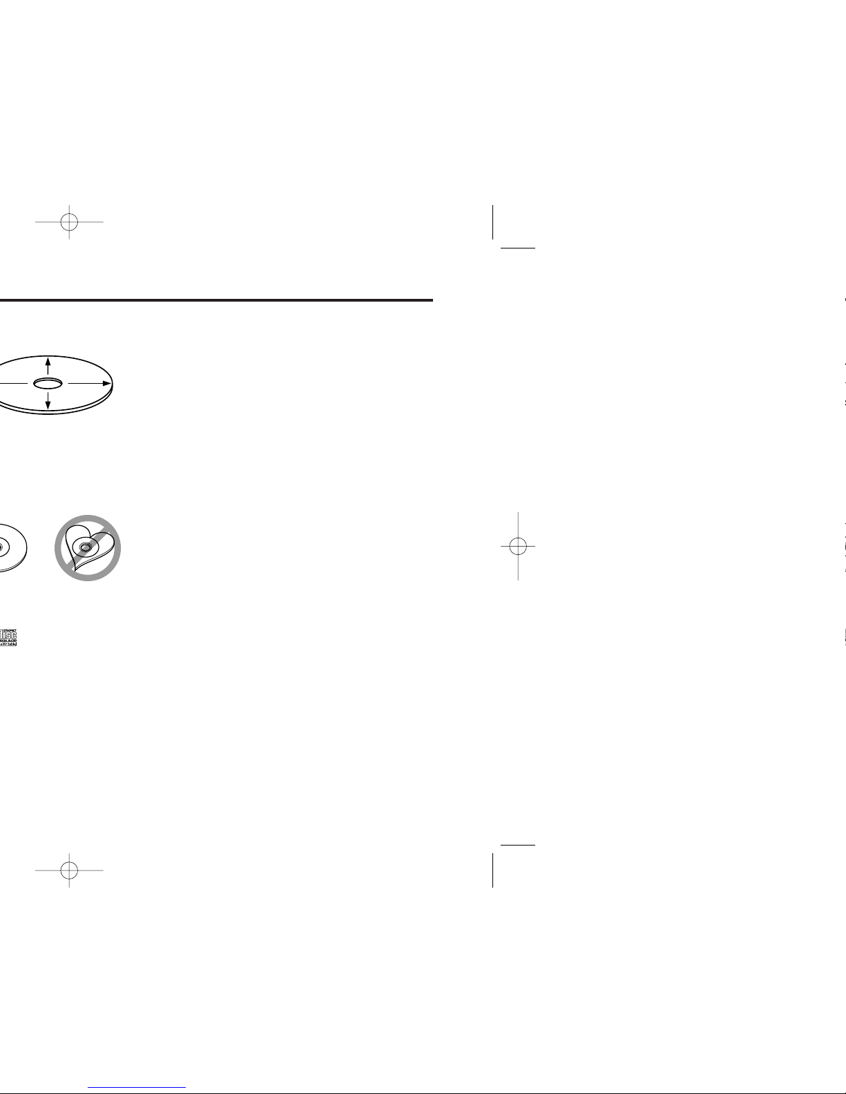
Do Not Load 8-cm (3-in.) CDs in the CD
slot
If you try to load an 8-cm CD with its adapter
into the unit, the adapter might separate from
the CD and damage the unit.

— 4 —
The marking of products using lasers
(Except for some areas)
The label is attached to the chassis/case and
says that the component uses laser beams
that have been classified as Class 1. It means
that the unit is utilizing laser beams that are of
a weaker class. There is no danger of
hazardous radiation outside the unit.
This Product is not installed by the
manufacturer of a vehicle on the production
line, nor by the professional importer of a
vehicle into an EU Member State.
CLASS 1
LASER PRODUCT
— 5 —
.
CD storage
• Don’t place them in direct sunlight (On the
seat or dashboard etc.) and where the
temperature is high.
• Store CDs in their cases.
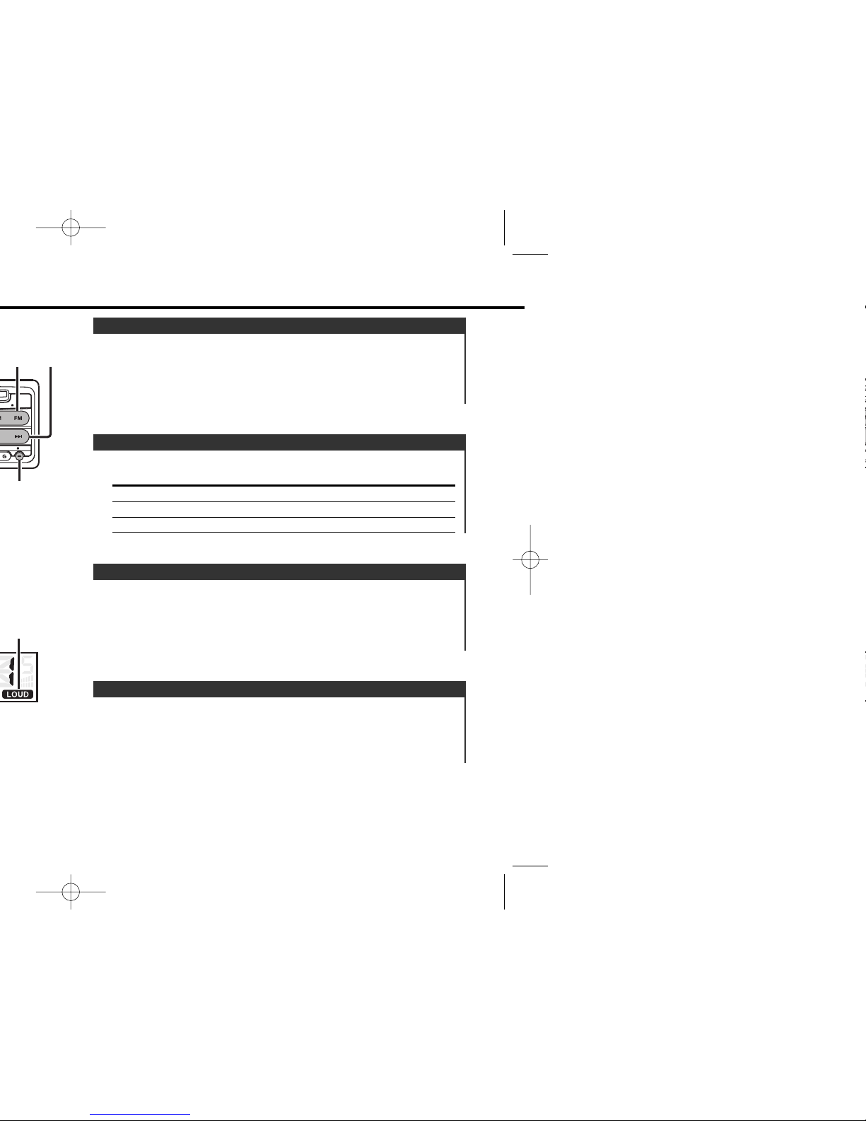
Turning the volume down quickly.
Press the [ATT] button.
Each time the button is pressed the Attenuator turns ON or OFF.
When it’s ON, the "ATT" indicator blinks.
Attenuator
Increasing Volume
Press the [u] button.
Decreasing Volume
Press the [d] button.
Volume
Press the [SRC] button.
Source required Display
Tuner "TUnE"
CD "CD"
Standby (Illumination only mode) "STBY"
Selecting the Source
Turning ON the Power
Press the [SRC] button.
Turning OFF the Power
Press the [SRC] button for at least 1 second.
Power
— 6 —
CLK ADJ
¢4
CLK/
ADJ
MONO
1 Select the source for adjustment
Press the [SRC] button.
2 Enter Audio Control mode
Press the [AUD] button for at least 1 second.
3 Select the Audio item for adjustment
Press the [FM] or [AM] button.
Each time the button is pressed the items that can be adjusted
switch as shown below.
4 Adjust the Audio item
Press the [4] or [¢] button.
Adjustment Item Display Range
Bass level "BAS" –8 — +8
Middle level "MID" –8 — +8
Treble level "TRE" –8 — +8
Balance "BL" Left 15 — Right 15
Fader "FD" Rear 15 — Front 15
5 Exit Audio Control mode
Press the [AUD] button.
Audio Control
— 7 —
A red indicator will blink on the unit after the faceplate is
removed, warning potential thieves.
1 Turn the power OFF
Press the [SRC] button for at least 1 second.
2 Set the DSI
While pressing the [1] and [3] button, press the [SRC] button.
Each time the step 1 and 2 operation is done the DSI turns ON or
OFF.
DSI (Disabled System Indicator)
1 Select the clock display
Press the [CLK] button.
2 Enter clock adjustment mode
Press the [ADJ] button for at least 2 seconds.
The clock display blinks.
3 Adjust the hours
Press the [FM] or [AM] button.
Adjust the minutes
Press the [4] or [¢] button.
4 Exit clock adjustment mode
Press the [CLK] button.
Adjusting Clock
— 8 —
Tuner features
— 9 —
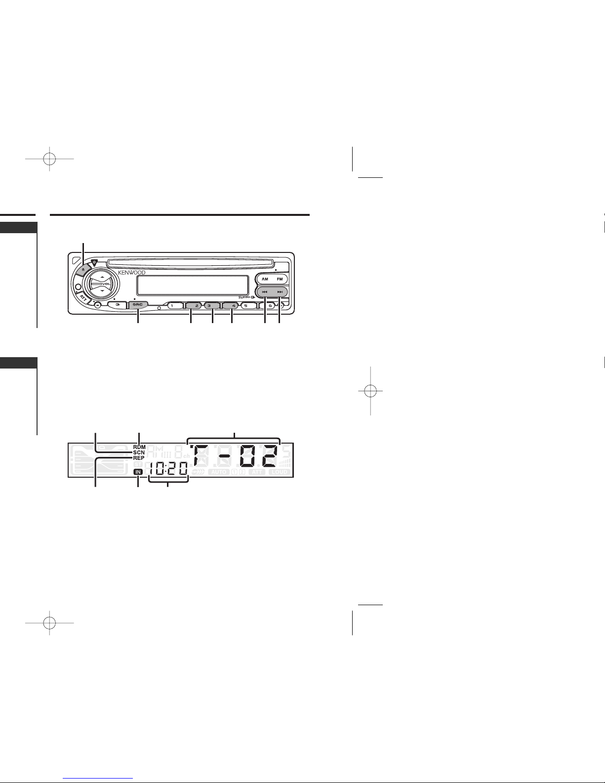
MONO
CLK ADJ
AUTO
AME
SCAN
AUD
RDM REP
OFF
LOUD
AM
FM/
MONO
¢4
SRC
1 - 6
AUTO/
AME
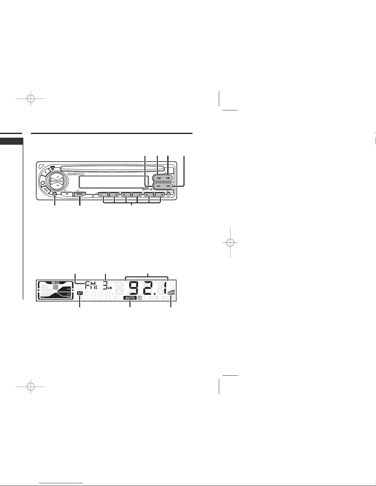
Monaural indicatorST indicator
Band display Preset station number Frequency display
AUTO indicator
Putting the station in the memory.
1 Select the band
Press the [FM] or [AM] button.
2 Select the frequency to put in the memory
Press the [4] or [¢] button.
3 Put the frequency in the memory
Press the [1] — [6] button for at least 2 seconds.
The preset number display blinks 1 time.
On each band, 1 station can be put in the memory on each [1] —
[6] button.
Station Preset Memory
Noise can be reduced when stereo broadcasts are received as
monaural.
Press the [MONO] button for at least 1 second.
Each time the button is pressed for at least 1 second the
Monaural Reception turns ON or OFF.
When it's ON, the Monaural indicator is ON.
Monaural Reception
— 10 —
CD player features
— 11 —
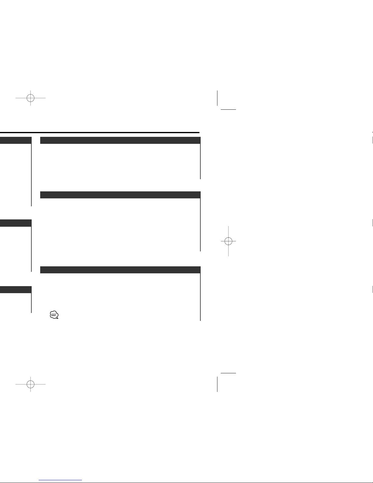
MONO
CLK ADJ
AUTO
AME
SCAN
AUD
RDM REP
OFF
LOUD
¢4
SCAN
0
RDM REP
SRC
RDM
indicator
SCN
indicator
REP indicator
Track time
Track number
IN indicator
Playing all the songs on the disc in random order.
Press the [RDM] button.
Each time the button is pressed Random Play turns ON or OFF.
When it's ON, the "RDM" indicator is ON and the track number
blinks.
When the [¢] button is pressed, the next song select starts.
Random Play
Playing the first part of each song on the disc you are listening
to and searching for the song you want to listen to.
1 Start Track Scan
Press the [SCAN] button.
"SCN" indicator is ON.
2 Release it when the song you want to listen to is played
Press the [SCAN] button.
Track Scan
Replaying the song you're listening to.
Press the [REP] button.
Each time the button is pressed the Track Repeat turns ON or
OFF.
When it's ON, the "REP" indicator is ON.
Track Repeat
— 12 —
— 13 —
• If your car is not prepared for this special connection-system,
consult your Kenwood dealer.
• Only use antenna conversion adapters (ISO-JASO) when the
antenna cord has an ISO plug.
• Make sure that all wire connections are securely made by
inserting jacks until they lock completely.
• If your vehicle's ignition does not have an ACC position, or if the
ignition wire is connected to a power source with constant
voltage such as a battery wire, the power will not be linked with
the ignition (i.e., it will not turn on and off along with the
ignition). If you want to link the unit's power with the ignition,
connect the ignition wire to a power source that can be turned
on and off with the ignition key.
• If the fuse blows, first make sure that the wires have not caused
a short circuit, then replace the old fuse with one with the same
rating.
• Insulate unconnected wires with vinyl tape or other similar
material. To prevent short circuits, also do not remove the caps
on the ends of the unconnected wires or the terminals.
• Connect the speaker wires correctly to the terminals to which
they correspond. The unit may receive damage or fail to work if
you share the - wires and/or ground them to any metal part in
the car.
• After the unit is installed, check whether the brake lamps,
indicators, wipers, etc. on the car are working properly.
• If the console has a lid, make sure to install the unit so that the
faceplate does not hit the lid when closing and opening.
•Mount the unit so that the mounting angle is 30° or less.
2CAUTION
— 14 —
1234567
8
1234567
8
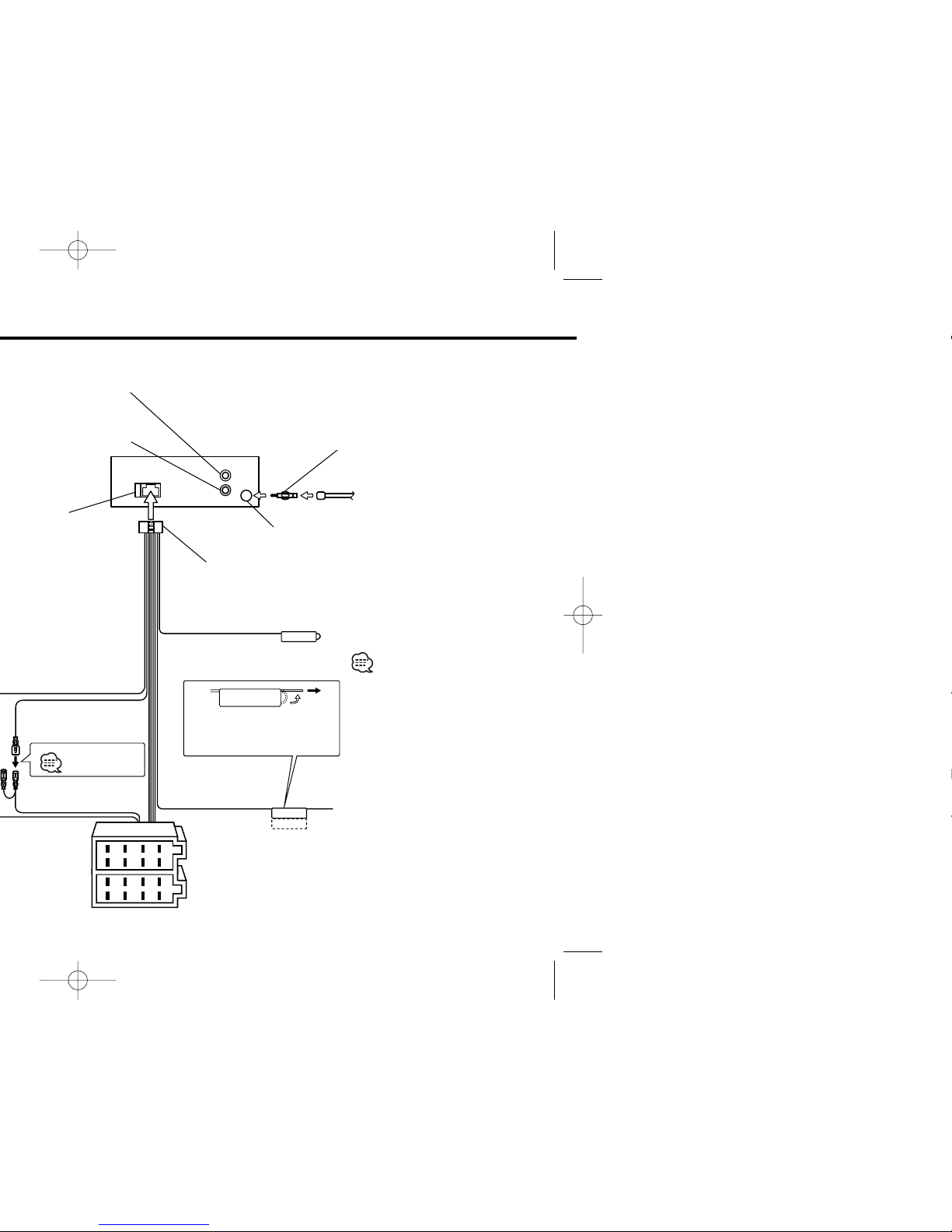
TEL MUTE
P.CONT
ANT.CONT
REAR
L
R
Rear right output (Red)4
10
Rear left output (White)
Battery wire (Yellow) 6
Ignition wire (Red) 7
FM/AM antenna
input 3
Antenna Cord (ISO) 1
Antenna Conversion Adaptor
(ISO–JASO) (Accessory3) 2
Wiring harness
(Accessory1) 16
If no connections are
made, do not let the wire
come out from the tab. 18
Power control/ Motor
antenna control wire
(Blue/White) 20
Connect either to the power
control terminal when using
the optional power amplifier,
or to the antenna control
terminal in the vehicle. 23
A–7 Pin (Red) 8
Connector A
Connector B
Fuse (10A) 13
Not Used 19
Do not let the wire
come out from the
tab. 4b
See page 15
— 15 —— 15 —
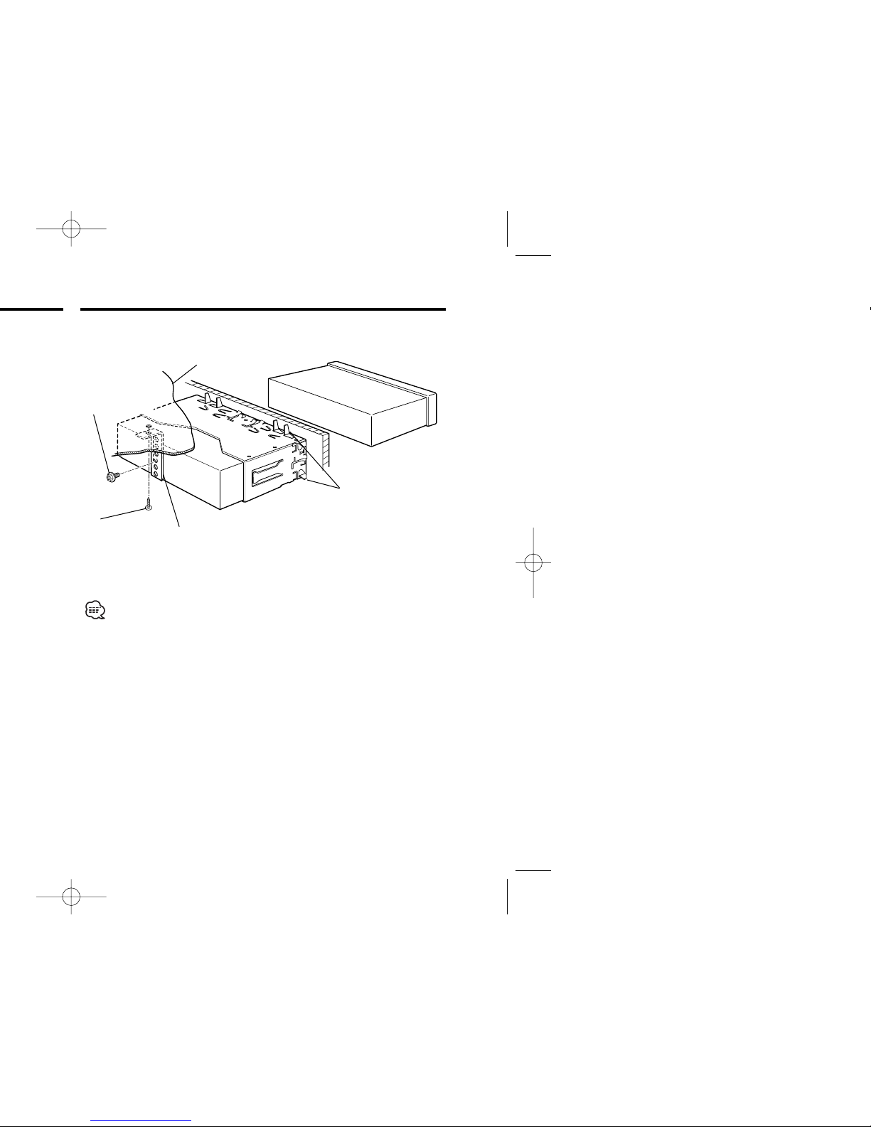
Make sure that the unit is installed securely in place. If the unit is
unstable, it may malfunction (eg, the sound may skip).
Bend the tabs of the
mounting sleeve
with a screwdriver or
similar utensil and
attach it in place.
Metal mounting
strap
(commercially
available)
Self-tapping
screw
(commercially
available)
Firewall or metal support
■ Installation
Screw (M4X8)
(commercially
available)
Installation
— 16 —— 16 —
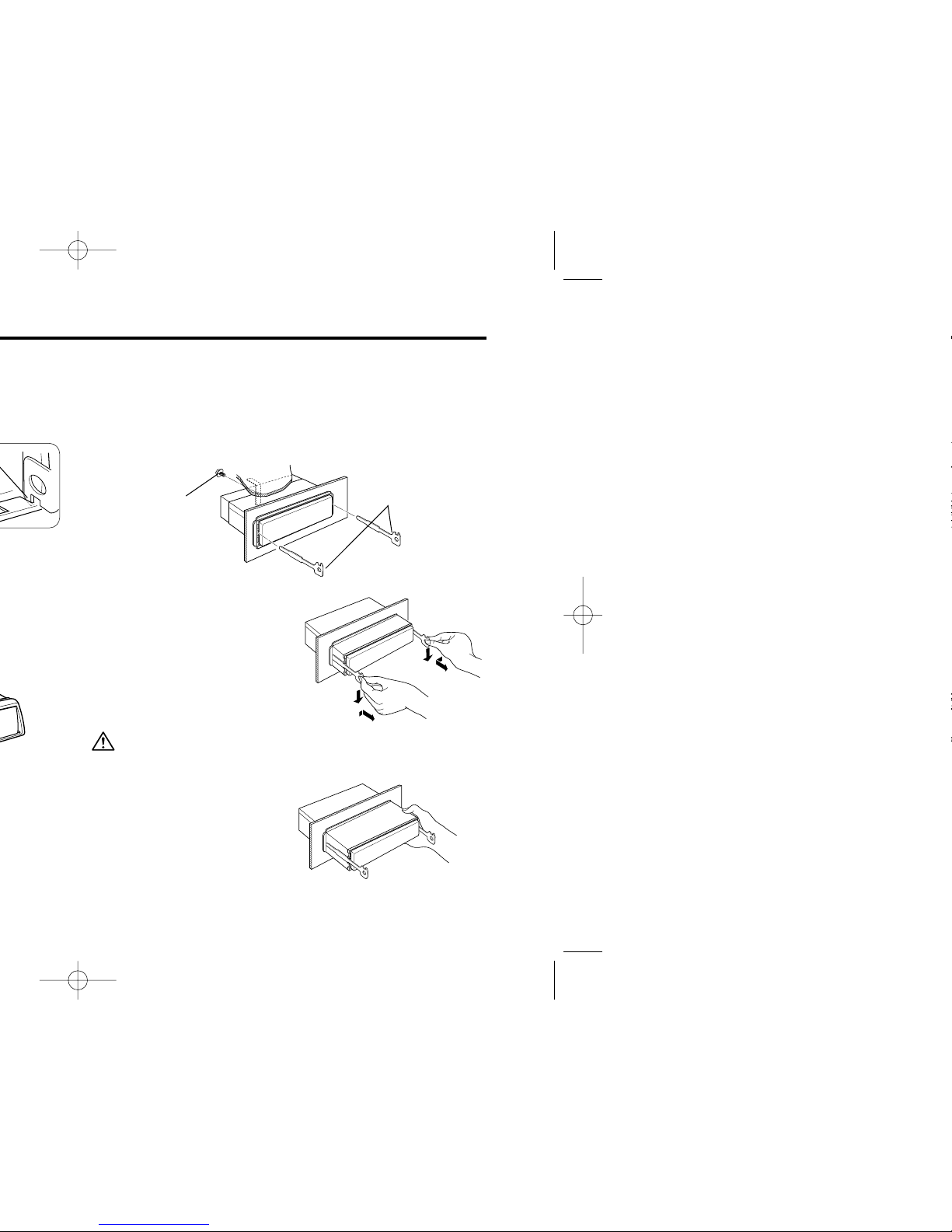
■ Removing the Unit
4 Lower the removal tool
toward the bottom, and pull
out the unit halfway while
pressing towards the inside.
5 Pull the unit all the way out
with your hands, being
careful not to drop it.
Be careful to avoid injury from the catch pins on the removal tool.
1 Refer to the section “Removing the hard rubber frame” and then
remove the hard rubber frame.
2 Remove the screw (M4×8) on the back panel.
3 Insert the two removal tools deeply into the slots on each side,
as shown.
Accessory2 Removal tool
Screw (M4X8)
(commercially
available)
— 17 —
? The sound quality is poor or distorted.25
✔ One of the speaker wires is being pinched by a screw in the car.
☞ Check the speaker wiring.
✔ The speakers are not wired correctly.27
☞ Reconnect the speaker wires so that each output terminal is
connected to a different speaker.
? The Touch Sensor Tone doesn’t sound.34
✔ The preout jack is being used.
☞ The Touch Sensor Tone can’t be output from the preout jack.
Tuner source
? Radio reception is poor.39
✔ The car antenna is not extended.
☞ Pull the antenna out all the way.
✔ The antenna control wire is not connected.40
☞ Connect the wire correctly, referring to the section on
<Connecting Wires to Terminals> (page 14).
 Loading...