

Page 1

DDX7035
DDX7045
DDX7065
MONITOR WITH DVD RECEIVER
INSTALLATION MANUAL
附DVD接收機顯示器
安裝說明書
附DVD接收機顯示器
安裝說明書
DVD수신기장착 모니터
설치설치
설치
설치설치
© PRINTED IN JAPAN B54-4432-00/00 (M)(AI)
설명서설명서
설명서
설명서설명서
Page 2
Before Installation
English
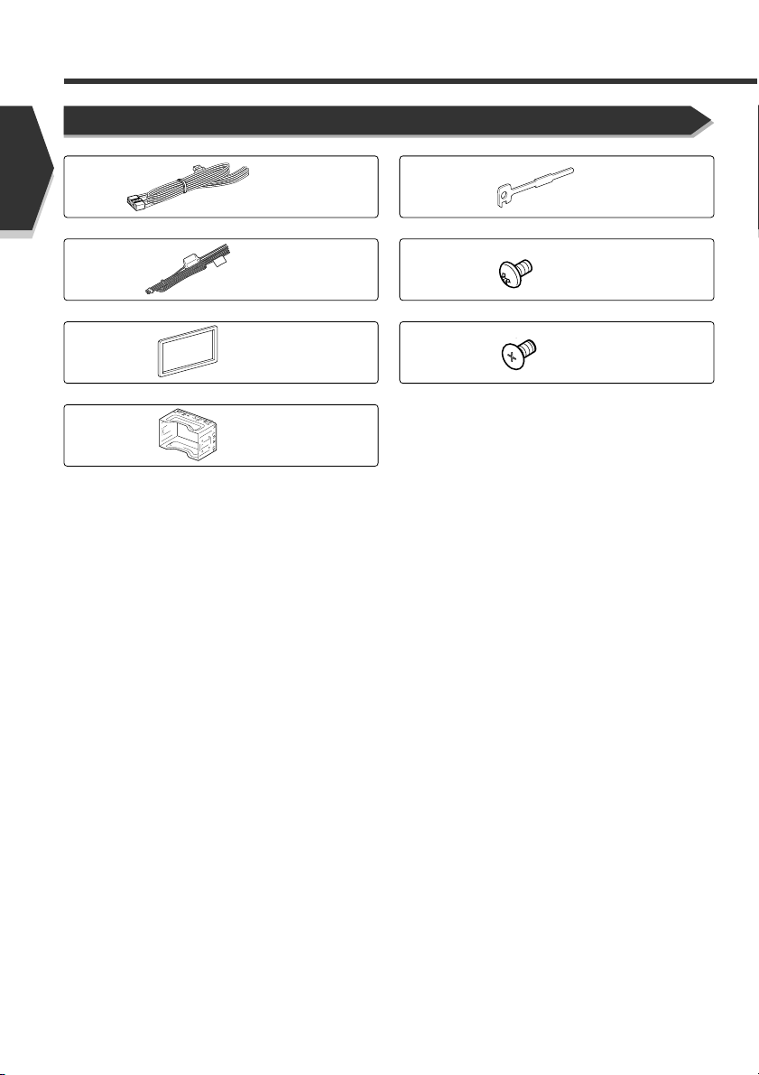
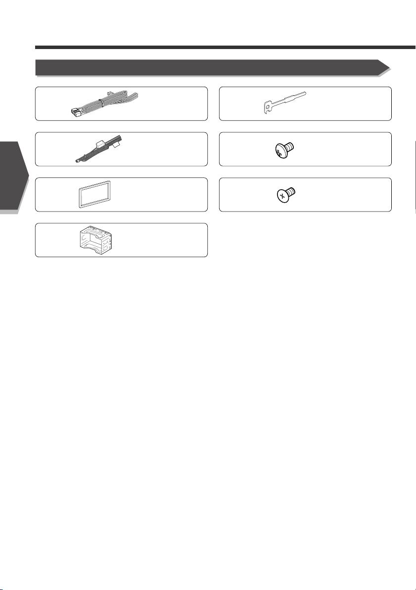
Accessories
1
2
3
4
..........1
..........1
..........1
..........1
5
..........2
6
..........6
7
..........6
2 English
Page 3

Installation Procedure
1. To prevent a short circuit, remove the key from the
ignition and disconnect the - battery.
2. Make the proper input and output wire connections for
each unit.
3. Connect the speaker wires of the wiring harness.
4. Connect the wiring harness wires in the following order:
ground, battery, ignition.
5. Connect the wiring harness connector to the unit.
6. Install the unit in your car.
7. Reconnect the - battery.
8. Press the reset button.
2WARNING
If you connect the ignition wire (red) and the battery wire
(yellow) to the car chassis (ground), you may cause a short
circuit, that in turn may start a fire. Always connect those
wires to the power source running through the fuse box.
2CAUTION
• If your car's ignition does not have an ACC position,
connect the ignition wires to a power source that can be
turned on and off with the ignition key. If you connect the
ignition wire to a power source with a constant voltage
supply, as with battery wires, the battery may die.
• If the console has a lid, make sure to install the unit so
that the faceplate will not hit the lid when closing and
opening.
• If the fuse blows, first make sure the wires aren’t
touching to cause a short circuit, then replace the old
fuse with one with the same rating.
• Insulate unconnected wires with vinyl tape or other
similar material. To prevent a short circuit, do not remove
the caps on the ends of the unconnected wires or the
terminals.
• Connect the speaker wires correctly to the terminals to
which they correspond. The unit may be damaged or fail
to work if you share the - wires or ground them to any
metal part in the car.
• When only two speakers are being connected to the
system, connect the connectors either to both the front
output terminals or to both the rear output terminals (do
not mix front and rear). For example, if you connect the
+ connector of the left speaker to a front output
terminal, do not connect the - connector to a rear
output terminal.
• After the unit is installed, check whether the brake
lamps, blinkers, wipers, etc. on the car are working
properly.
• Mount the unit so that the mounting angle is 30° or less.
English 3
Page 4
Connection
A
B
C
B
C
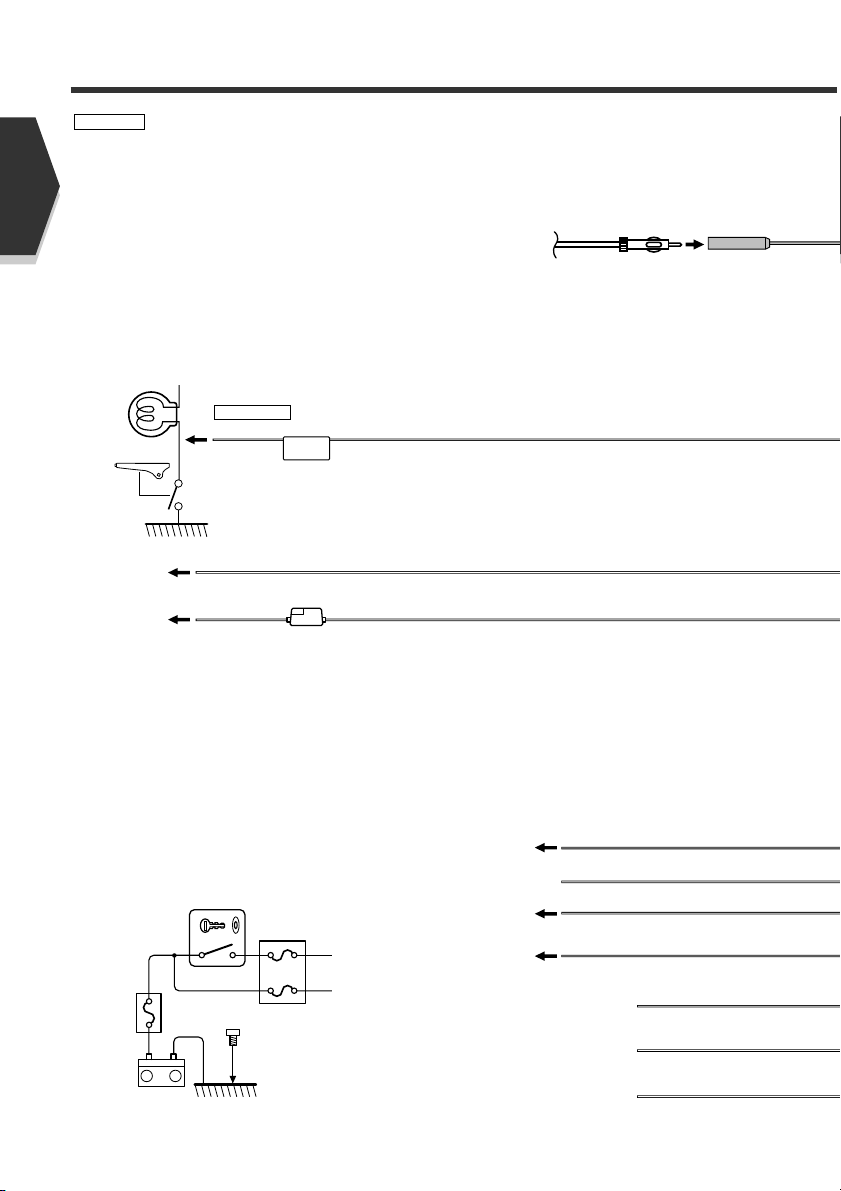
PRK SW
( 5A )
–
+
+
B
C
A
For the sake of safety, be sure to connect the parking sensor.
Connect to the vehicle's parking brake detection switch harness
using the supplied relay connector.
2CAUTION
Parking sensor wire (Green)
Ground wire (Black) - (To car chassis)
Battery wire
(Yellow)
Ignition key
switch
Battery
Car fuse box
ACC
Battery wire (Yellow)
Dimmer control wire (Orange/White)
To car light control switch
Ignition wire (Red)
Ground wire (Black) - (To car chassis)
Motor antenna control wire
(Blue)
Power control wire
(Blue/White)
External amplifier control wire
(Pink/Black)
FM/AM antenna input
Car fuse
box
(Main fuse)
Depending on what antenna you are using,
connect either to the control terminal of the motor
antenna, or to the power terminal for the booster
amplifier of the film-type antenna.
When using the optional power amplifier, connect
to its power control terminal.
To "EXT.AMP.CONT." terminal of the amplifier
having the external amp control function.
2WARNING
If you connect the ignition wire (red) and the battery wire (yellow) to the car chassis (ground),
English
you may cause a short circuit, that in turn may start a fire. Always connect those wires to the
power source running through the fuse box.
4 English
Page 5
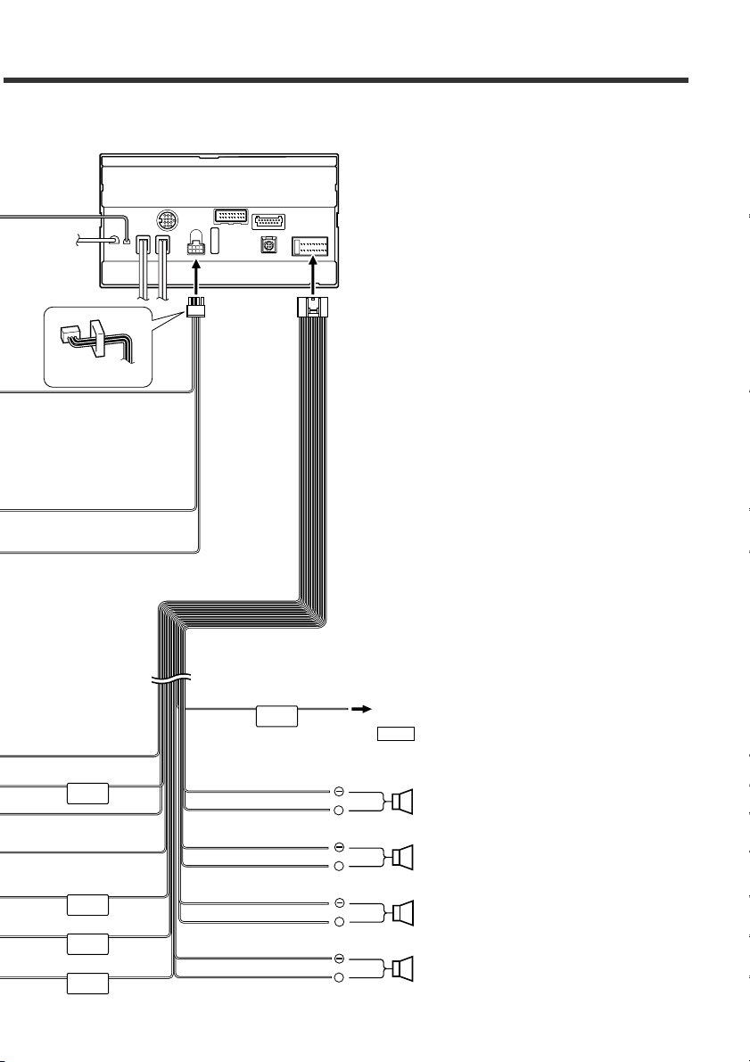
MUTE
ANT. CONT
P CONT
EXT.CONT
+
+
+
+
ILLUMI
White/Black
NOTE
To front left speaker
To front right speaker
To rear left speaker
To rear right speaker
Mute wire (Brown)
White
Gray/Black
Gray
Green/Black
Green
Purple/Black
Purple
Wiring harness
(Accessory 2)
Wiring harness
(Accessory 1)
Rear view
Connect to the terminal that is grounded when either the telephone
rings or during conversation.
To connect the KENWOOD navigation system, consult your
navigation manual.
English 5
Page 6
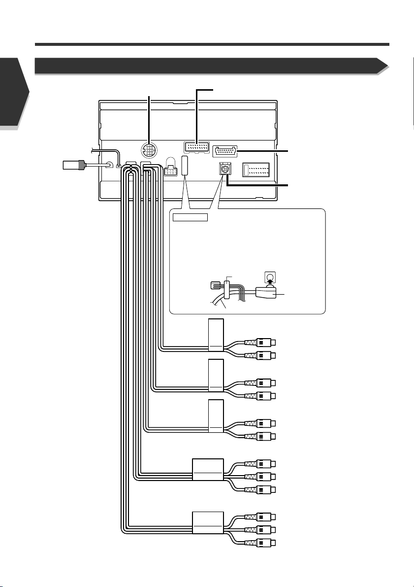
Connection
REARFRONT
AV IN
AV OUT
WOOFER
SUB
English
System Connection
To Disc Changer etc.
To Navigation System
2CAUTION
To TV Tuner unit
To DSP unit
Optical input for
DSP unit
Wire an optical cable after fixing it with the clamp
on the back of the unit.
Do not bend the optical cable within a minimum
radius of 30 mm, or it may be damaged.
When you install the unit, ensure that the optical
cable is not stuck between the unit and the
vehicle parts.
clamp
optical cable
≥30R
• Sub-woofer (Mono) Preout
Audio left output (White)
Audio right output (Red)
• Rear Preout
Audio left output (White)
Audio right output (Red)
• Front Preout
Audio left output (White)
Audio right output (Red)
6 English
• Audio/Visual Output
Visual output (Yellow)
Audio left output (White)
Audio right output (Red)
• Audio/Visual input
Visual input (Yellow)
Audio left input (White)
Audio right input (Red)
Page 7
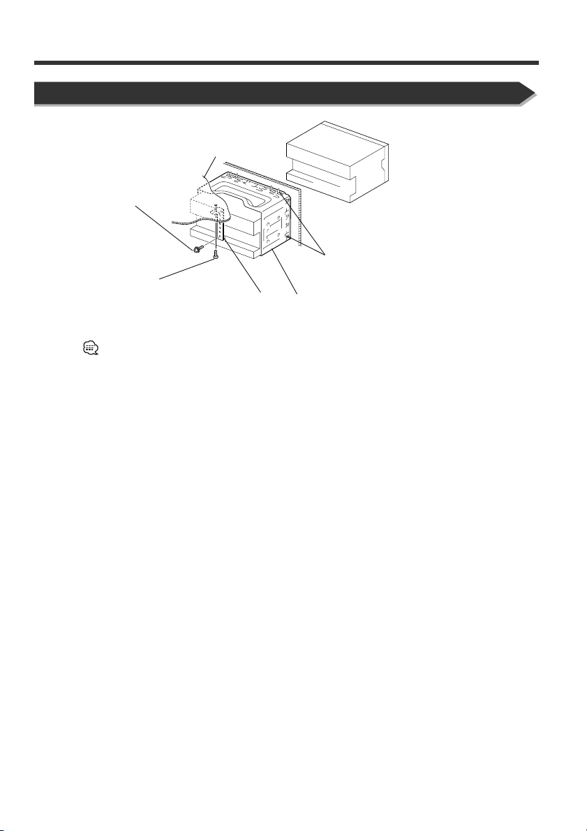
Installation
Installation for Monitor/Player Unit
Firewall or metal support
Screw (M4X8)
(commercially available)
Self-tapping screw
(commercially available)
Make sure that the unit is installed securely in place. If the unit is
unstable, it may malfunction (eg, the sound may skip).
Metal mounting strap
(commercially available)
Accessory 4
Bend the tabs of the mounting sleeve
with a screwdriver or similar utensil
and attach it in place.
English 7
Page 8
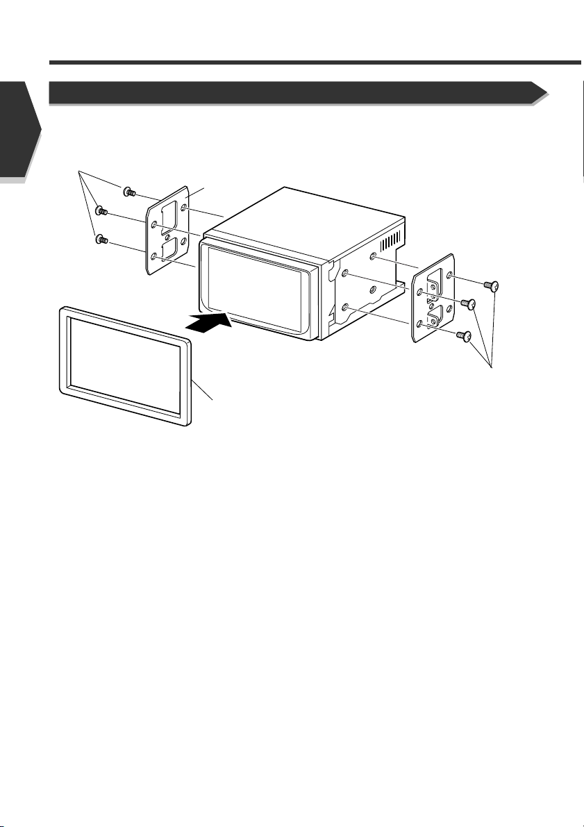
Installation
English
Accessory 6 or 7
Installing in Japanese-Made Cars
Bracket
Accessory 3
(For NISSAN Car)
Accessory 6 or 7
8 English
Page 9
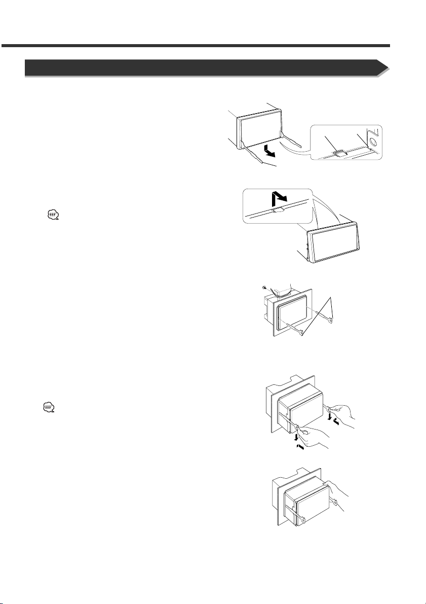
Removing Monitor/Player Unit
■ Removing the Hard Rubber Frame (escutcheon)
1. Engage the catch pins on the removal tool 5 and
remove the two locks on the lower level.
Lower the frame and pull it forward as shown in the
figure.
2. When the lower level is removed, remove the upper
two locations.
The frame can be removed from the top side in the
same manner.
■ Removing the Unit
1. Refer to the section <Removing the Hard Rubber
Frame> and then remove the hard rubber frame.
2. Remove the Hex-head screw with integral washer (M4
6) on the back panel.
3. Insert the two removal tools 5 deeply into the slots on
each side, as shown.
Catch
Lock
Accessory 5
×
Accessory 5
4. Lower the removal tool toward the bottom, and pull out
the unit halfway while pressing towards the inside.
Be careful to avoid injury from the catch pins on the
removal tool.
5. Pull the unit all the way out with your hands, being
careful not to drop it.
English 9
Page 10
安裝之前
附件
中文(繁體字)
1
.................. 1
2
.................. 1
3
.................. 1
4
.................. 1
5
.................. 2
6
.................. 6
7
.................. 6
中文(繁體字)
10
Page 11
安裝程序
1. 為了防止短路﹐從點火開關中拔出鑰匙﹐拆下蓄電池的負
極 - 接線。
2. 連接各裝置的輸入、輸出導線。
3. 連接電線束的揚聲器導線。
4. 按照接地導線、蓄電池導線和點火導線的順序連接電線
束。
5. 將電線束的連接器連接到裝置上。
6. 將裝置安裝到汽車中。
7. 重新連接蓄電池的負極 - 接線。
8. 按下復位按鈕。
2警告
如果您將點火裝置電線(紅)和電池線(黃)連接到汽車底
盤 (接地)﹐您可能會導致短路﹐並造成火災。請始終將那
些電線連接到經過保險絲盒的電源。
2注意
• 如果汽車的點火裝置沒有ACC位置﹐請將點火導線與可以
通過點火鑰匙接通和斷開的電源連接。如果將點火導線與
始終供電的電源連接﹐例如與蓄電池導線連接﹐蓄電池將
全部放電而無法使用。
• 如果控制台設有蓋板﹐在安裝時請注意﹐當關閉和打開面
板時﹐不得與蓋板碰撞。
• 當保險絲燒斷時﹐請首先確認不應有引起短路的接觸﹐然
後使用與舊保險絲相同規格的保險絲更換。
• 請用乙烯帶等絕緣物包覆未連接的導線。為了防止發生短
路﹐不得取下未連接導線的線端或端子的護罩。
• 將揚聲器導線直接與對應的端子連接。如果共用負極 導線或者將其與汽車的金屬部件連接﹐本裝置可能損壞
或者無法正常工作。
• 當衹有兩衹揚聲器與系統連接時﹐請將連接器或者與兩個
前側輸出端子連接、或者與兩個後側輸出端子連接(不得
將前側與後側混合連接)。例如﹐如果將左側揚聲器的正
極 + 連接器與前側輸出端子連接﹐則不得將負極 -連接
器與後側輸出端子連接。
• 安裝結束後﹐請確認汽車制動器燈、方向指示燈和刮水器
等是否正常動作。
• 本機安裝角度為30度以下為宜。
中文(繁體字)
11
Page 12

A
B
C
B
C
PRK SW
( 5A )
–
+
+
B
C
A
連接
2警告
如果您將點火裝置電線(紅)和電池線(黃)連接到汽車底盤(接地)﹐您可
能會導致短路﹐並造成火災。請始終將那些電線連接到經過保險絲盒的電源。
中文(繁體字)
使用配備的中繼連接器連接到汽車的手剎車檢測開關線束。
2注意
為了安全、請確保連接手剎車傳感器。
手剎車傳感器電線(綠)
接地線(黑)-(連接到汽車底盤)
電池線(黃)
FM/AM 天線輸入
汽車保險絲盒
(主保險絲)
中文(繁體字)
12
電池
點火開關
汽車保險絲盒
連接到燈光控製開關
ACC
根據您使用天線的情況、請連接到電動天線
的控製端子、或者連接到薄膜型天線增強放
當使用選購的功率放大器時、請連接
連接到有外部放大器控製功能的放大器
“EXT.AMP.CONT(外部放大器控製)”端子。
電池線(黃)
減光控製電線(橙/白)
點火裝置電線(紅)
接地線(黑)-(連接到汽車底盤)
大器的功率端子。
到它的功率控製端子。
電動天線控製電線(藍)
功率控製電線(藍/白)
外部放大器控製電線
(粉紅/黑)
Page 13

後視
ILLUMI
ANT. CONT
P CONT
EXT.CONT
電線線束
(附件 2)
靜音導線(棕色)
MUTE
白/黑
灰/黑
綠/黑
紫/黑
電線線束
(附件 1)
+
白
+
灰
+
綠
+
紫
連接到電話振鈴或通話時接地的端子上。
註
請參照導航系統的使用說明書、連接KENWOOD
導航系統。
向前置左揚聲器
向前置右揚聲器
向後置左揚聲器
向後置右揚聲器
中文(繁體字)
13
Page 14

連接
系統連接
中文(繁體字)
至光盤換片機等
至導航系統
至TV調諧器裝置
至DSP裝置
DSP裝置的光學輸入
2注意
在本機的背面使用夾子固定後﹐連接光學連接線。
不得以小於30mm的半徑彎曲光學連接線、否則將發生
損壞。
在安裝本機時、不得將光學連接線夾在本機和車輛部件
之間。
夾子
光學連接線
≥ 30R
SUB
WOOFER
REARFRONT
• 低音揚聲器 (單聲道) 預輸出
音頻左輸出 (白)
音頻右輸出 (紅)
• 后預輸出
音頻左輸出 (白)
音頻右輸出 (紅)
中文(繁體字)
14
AV OUT
AV IN
• 音頻左輸出 (白)
音頻右輸出 (紅)
• 音頻/視頻輸入
視頻輸出 (黃)
音頻左輸出 (白)
音頻右輸出 (紅)
• 音頻/視頻輸出
視頻輸入 (黃)
音頻左輸入 (白)
音頻右輸入 (紅)
Page 15

安裝
安裝顯示器/播放裝置
隔熱牆或金屬支撐
螺絲(M4×8)
(選購)
安裝套盒用螺絲刀
等折彎凸耳部位﹐
將其固定。
自攻絲螺絲
(選購)
請切實固定裝置。若安裝不穩﹐可能會出故障。
金屬安裝固定
夾板(選購)
附件 4
中文(繁體字)
15
Page 16

連接
在日本汽車上安裝時
附件 6 或者 7
中文(繁體字)
托架
附件 3
(對於NISSAN
(日產牌)汽車)
附件 6 或者 7
中文(繁體字)
16
Page 17

拆除顯示器/播放裝置
■ 硬橡膠框的拆卸方法
1. 拉出可拆工具 5 的凸耳﹐拆卸下側兩處的鎖定裝置。
按圖示要領將框向下壓﹐再向後拉出。
2. 下側拆卸後﹐上側兩處也以同樣方法拆卸。
從上側開始也可同樣拆卸。
■ 拆卸方法
附件 5
鎖定裝置
凸耳
1. 請參照〈硬橡膠框的拆卸方法〉拆卸硬橡膠框。
2. 卸下背面板附有的墊圈螺絲(M4×6)。
3. 將可拆工具 5 深深插入裝置的槽內。
4. 將可拆工具向下降﹐靠近內側﹐將裝置拉出到中途。
安裝時請注意不要被可拆工具的凸耳碰傷。
5. 用手托住裝置拉出﹐以免掉落。
附件 5
中文(繁體字)
17
Page 18

安裝之前
附件
中文(簡體字)
1
...................... 1
2
...................... 1
3
...................... 1
4
...................... 1
5
...................... 2
6
...................... 6
7
...................... 6
中文(簡體字)
18
Page 19

安裝程序
1. 為了防止短路﹐從點火開關中拔出鑰匙﹐拆下蓄電池的負
極 - 接線
。
2. 連接各裝置的輸入﹑輸出導線。
3. 連接電線束的揚聲器導線。
4. 按照接地導線﹑蓄電池導線和點火導線的順序連接電線
。
束
5. 將電線束的連接器連接到裝置上。
6. 將裝置安裝到汽車中。
7. 重新連接蓄電池的負極 - 接線。
8. 按下復位按鈕。
2警告
如果您將點火裝置電線(紅)和電池線(黃)連接到汽車底
盤 (接地)﹐您可能會導致短路﹐並造成火災
些電線連接到經過保險絲盒的電源
。
。請始終將那
2注意
‧ 如果汽車的點火裝置沒有A CC位置﹐請將點火導線與可以
通過點火鑰匙接通和斷開的電源連接
始終供電的電源連接﹐例如與蓄電池導線連接﹐蓄電池將
全部放電而無法使用
‧ 如果控制台設有蓋板﹐在安裝時請注意﹐當關閉和打開面
板時﹐不得與蓋板碰撞
‧ 當保險絲燒斷時﹐請首先確認不應有引起短路的接觸﹐然
後使用與舊保險絲相同規格的保險絲更換
‧ 請用乙烯帶等絕緣物包覆未連接的導線。為了防止發生短
路﹐不得取下未連接導線的線端或端子的護罩
‧ 將揚聲器導線直接與對應的端子連接。如果共用負極 -
導線或者將其與汽車的金屬部件連接﹐本裝置可能損壞
或者無法正常工作
‧ 當衹有兩衹揚聲器與系統連接時﹐請將連接器或者與兩個
前側輸出端子連接﹑或者與兩個後側輸出端子連接(不得
將前側與後側混合連接)
極 + 連接器與前側輸出端子連接﹐則不得將負極 - 連接
器與後側輸出端子連接
‧ 安裝結束後﹐請確認汽車制動器燈﹑方向指示燈和刮水器
等是否正常動作
。
。
。
。例如﹐如果將左側揚聲器的正
。
。
。如果將點火導線與
。
。
‧ 本機安裝角度為30度以下為宜。
中文(簡體字)
19
Page 20

A
B
C
B
C
PRK SW
( 5A )
–
+
+
B
C
A
連接
2警告
如果您將點火裝置電線(紅)和電池線(黃)連接到汽車底盤(接地)﹐您可
能會導致短路﹐並造成火災
中文(簡體字)
。請始終將那些電線連接到經過保險絲盒的電源。
使用配備的中繼連接器連接到汽車的手剎車檢測開關線束。
2注意
為了安全﹑請確保連接手剎車傳感器
接地線(黑)-(連接到汽車底盤)
電池線(黃)
。
手剎車傳感器電線(綠)
FM/AM 天線輸入
汽車保險絲盒
(主保險絲)
中文(簡體字)
20
電池
點火開關
汽車保險絲盒
ACC
電池線(黃)
連接到燈光控製開關
根據您使用天線的情況﹑請連接到電動天線
的控製端子﹑或者連接到薄膜型天線增強放
當使用選購的功率放大器時﹑請連接
連接到有外部放大器控製功能的放大器
“EXT.AMP.CONT(外部放大器控製)”端子
減光控製電線(橙/白)
點火裝置電線(紅)
接地線(黑)-(連接到汽車底盤)
大器的功率端子
到它的功率控製端子
電動天線控製電線(藍)
。
功率控製電線(藍/白)
。
外部放大器控製電線
(粉紅/黑)
。
Page 21

後視
ILLUMI
ANT. CONT
P CONT
EXT.CONT
電線線束
(附件 2)
靜音導線(棕色)
MUTE
白/黑
灰/黑
綠/黑
紫/黑
電線線束
(附件 1)
+
白
+
灰
+
綠
+
紫
連接到電話振鈴或通話時接地的端子上
。
注
請參照導航系統的使用說明書﹑連接KENWOOD
。
導航系統
向前置左揚聲器
向前置右揚聲器
向後置左揚聲器
向後置右揚聲器
中文(簡體字)
21
Page 22

連接
系統連接
中文(簡體字)
至光盤換片機等
至導航系統
至TV調諧器裝置
至DSP裝置
DSP裝置的光學輸入
2注意
在本機的背面使用夾子固定後﹐連接光學連接線
不得以小於30mm的半徑彎曲光學連接線﹑否則將發生損
壞
。
在安裝本機時﹑不得將光學連接線夾在本機和車輛部件
之間
。
夾子
≥ 30R
SUB
WOOFER
REARFRONT
。
光學連接線
• 低音揚聲器 (單聲道) 預輸出
音頻左輸出 (白)
音頻右輸出 (紅)
• 后預輸出
音頻左輸出 (白)
音頻右輸出 (紅)
• 前預輸出
音頻左輸出 (白)
音頻右輸出 (紅)
• 音頻/視頻輸出
AV OUT
視頻輸出 (黃)
音頻左輸出 (白)
音頻右輸出 (紅)
• 音頻/視頻輸入
AV IN
視頻輸入 (黃)
音頻左輸入 (白)
音頻右輸入 (紅)
中文(簡體字)
22
Page 23

安裝
安裝顯示器/播放裝置
隔熱牆或金屬支撐
螺絲(M4×8)
(選購)
安裝套盒用螺絲刀
等折彎凸耳部位﹐
。
將其固定
自攻絲螺絲
(選購)
請切實固定裝置。若安裝不穩﹐可能會出故障。
附件 4
金屬安裝固定
夾板(選購)
中文(簡體字)
23
Page 24

連接
在日本汽車上安裝時
附件 6 或者 7
中文(簡體字)
托架
附件 3
(對於NISSAN
(日產牌)汽車)
附件 6 或者 7
中文(簡體字)
24
Page 25

拆除顯示器/播放裝置
■ 硬橡膠框的拆卸方法
1. 拉出可拆工具 5 的凸耳﹐拆卸下側兩處的鎖定裝置。
按圖示要領將框向下壓﹐再向後拉出。
2. 下側拆卸後﹐上側兩處也以同樣方法拆卸。
從上側開始也可同樣拆卸。
■ 拆卸方法
附件 5
鎖定裝置
凸耳
1. 請參照〈硬橡膠框的拆卸方法〉拆卸硬橡膠框。
2. 卸下背面板附有的墊圈螺絲(M4×6)。
3. 將可拆工具 5 深深插入裝置的槽內。
4. 將可拆工具向下降﹐靠近內側﹐將裝置拉出到中途。
安裝時請注意不要被可拆工具的凸耳碰傷。
5. 用手托住裝置拉出﹐以免掉落。
附件 5
中文(簡體字)
25
Page 26

설치하기설치하기
설치하기
설치하기설치하기
부속품부속품
부속품
부속품부속품
전에전에
전에
전에전에
한
한한
한한
글
글글
글글
1
.................. 1
2
.................. 1
3
.................. 1
4
.................. 1
5
.................. 2
6
.................. 6
7
.................. 6
26
한한
글글
한
글
한한
글글
Page 27

설치설치
설치
설치설치
순서순서
순서
순서순서
1. 단락을 방지하기 위해 이그니션에서 키를 빼고 - 배터리
를 차단합니다.
2. 각 기기의 입출력 와이어를 바르게 접속합니다.
3. 와이어링 하네스와 스피커 와이어를 접속합니다.
4. 어스,배터리,이그니션의 순서로 와이어링 하네스의 와
이어를 접속합니다.
5. 와이어링 하네스 커넥터를 본 기기에 접속합니다.
6. 자동차에 본 기기를 설치합니다.
7. - 배터리를 다시 접속합니다.
8. 리세트 버튼을 누릅니다.
2경고
이그니션 와이어 (빨강) 와 배터리 와이어 (노랑) 를 차대 (접
지) 에 연결할 때에 전기 누전을 일으켜 발화할 수도 있습니
다. 이들 와이어는 항상 휴즈 박스를 관통하는 전원 소스에
연결하십시오.
2주의
• 자동차의 이그니션에 ACC 위치가 없는 경우에는 이그니
션 키를 사용하여 ON/OFF 로 할 수 있는 전원에 이그니
션 와이어를 접속합니다. 배터리 와이어 처럼 일정 전압
의 전원에 이그니션 와이어를 접속하면 배터리가 움직이
지 않습니다.
• 기기에 뚜껑이 있는 경우, 개폐시 전면 플레이트가 뚜껑에
부딛치지 않는지 확인해서 설치하십시오.
• 퓨즈가 끊어졌을 경우에는 단락의 원인이 되므로 와이어
가 접촉하고 있지 않음을 확인하고 나서 같은 규격의 새 퓨
즈로 교환해 주십시오.
• 연결되지 않은 와이어는 비닐 테이프 등으로 절연시키십
시오.누전을 방지하기 위해서 연결되지 않은 와이어, 혹
은 단자의 끝에 있는 캡을 제거하지 마십시오.
• 스피커 와이어를 해당 단자에 바르게 접속합니다. - 와이
어를 공유하거나 자동차의 금속부분에 어스를 연결하면
본 기기가 고장이 나거나 오작동할 수도 있습니다.
• 두개의 스피커가 시스템에 연결되어져 있을 경우에는 출
력 단자의 앞의 양쪽, 혹은 출력 단자의 후반의 양쪽에 커
넥터를 연결하십시오 (앞쪽과 후반부를 섞어서 연결하지
마십시오). 예를 들어, 왼쪽 스피커의 + 커넥터를 앞쪽의
출력 단자에 연결했다면, - 커넥터를 후반 출력 단자에
연결하면 안됩니다.
•본 기기를 설치한 후에 자동차의 브레이크 램프,점멸
기,와이퍼가 정삭으로 작동하고 있는지 확인해 주십시
오.
•설치 각도가 30 도 이하로 되도록 본 기기를 설치해 주십시
오.
한한
한
한한
글글
글
27
글글
Page 28

A
B
C
B
C
PRK SW
( 5A )
–
+
+
B
C
A
접속접속
접속
접속접속
2경고
이그니션 와이어 (빨강) 와 배터리 와이어 (노랑) 를 차대 (접지) 에 연결할 때에
전기 누전을 일으켜 발화할 수도 있습니다. 이들 와이어는 항상 휴즈 박스를
관통하는 전원 소스에 연결하십시오.
제공되는 릴레이 단자를 사용해서 자동차의 주차
브레이크 탐지 스위치에 접속합니다.
2주의
안전을 위해서, 주차 센서를 접속하십시오.
주차 센서 와이어 (녹색)
지선(검은색) - (자동차의 새시에)
배터리 와이어
(황색)
한
한한
한한
글
글글
글글
AM/FM 안테나 입력
28
퓨즈 복스
(메인 퓨즈)
한한
한
한한
잗동차의
글글
글
글글
배터리
이그니션 키
스위치
잗동차의
퓨즈 복스
ACC
배터리 와이어 (황색)
자동차 라이트 컨트롤 스위치에
사용하고 있는 안테나에 따라 모터 안테나
컨트롤단자 또는 필름 타입 안테나의 부스
터 증폭용 전원단자에 접속한다.
옵션의 앰프를 사용할 경우에 전원 컨
외부 앰프 컨트롤 기능을 가지는 앰프의
“EXT.AMP.CONT.”터미널에.
조광기 컨트롤 와이어 (오랜지/흰색)
이그니션 와이어 (빨간색)
지선(검은색) - (자동차의 새시에)
트롤 단자에 접속한다.
모터 안테나 컨트롤
와이어 (청색)
전원 컨트롤 와이어
(청색/흰색)
외부 앰프 컨트롤 와이어
(핑크/검은색)
Page 29

후면도후면도
후면도
후면도후면도
ILLUMI
ANT. CONT
P CONT
EXT.CONT
와이어링 하네스
(부속품 2)
뮤트 배선 (갈색)
MUTE
보라색/검은색
흰색/검은색
흰색
회색/검은색
회색
녹색/검은색
녹색
보라색
와이어링 하네스
(부속품 1)
전화 호출 또는 대화중 접지된 단자에 접속합니다.
주의
KENWOOD네비게이션 시스템을 연결하기위해서는
네비게이션 메뉴얼을 참조하십시오.
+
+
+
+
앞 왼쪽 스피커
앞 오른쪽 스피커
뒤 왼쪽 스피커
뒤 오른쪽 스피커
한한
한
한한
글글
글
29
글글
Page 30

접속접속
접속
접속접속
한
한한
한한
글
글글
글글
시스템시스템
시스템
시스템시스템
디스크디스크
디스크
디스크디스크
등으로등으로
등으로
등으로등으로
체인저체인저
체인저
체인저체인저
연결연결
연결
연결연결
네비게이션네비게이션
네비게이션
네비게이션네비게이션
시스템으로시스템으로
시스템으로
시스템으로시스템으로
2주의
기기의 후면에 있는 클램프로 광학 케이블을 고정한 후
에 배선을 하십시오.
광학 케이블은 손상될 수 있으므로, 최소 반경 30mm 이
하로 구부리지 마십시오.
기기를 설치한 때에는, 기기와 자동차의 부품사이에 광
학 케이블이 끼여있지 않는지 확인하십시오.
TV TV
TV
TV TV
SUB
WOOFER
튜너튜너
튜너
튜너튜너
크램프
≥ 30R
기기로기기로
기기로
기기로기기로
DSP DSP
기기로기기로
DSP
기기로
DSP DSP
기기로기기로
DSP DSP
기기를기기를
DSP
기기를
DSP DSP
기기를기기를
광학 케이블
서브서브
--
우퍼우퍼
( (
-
--
우퍼
우퍼우퍼
모노모노
(
모노
( (
모노모노
•
서브
서브서브
오디오 좌측 출력 (백색)
오디오 우측 출력 (적색)
위한위한
위한
위한위한
) )
예비출력예비출력
)
예비출력
) )
예비출력예비출력
광학광학
광학
광학광학
입력입력
입력
입력입력
30
후면후면
예비출력예비출력
•
후면
예비출력
후면후면
REARFRONT
AV OUT
AV IN
한한
글글
한
글
한한
글글
예비출력예비출력
오디오 좌측 출력 (백색)
오디오 우측 출력 (적색)
전면전면
예비출력예비출력
•
전면
예비출력
전면전면
예비출력예비출력
오디오 좌측 출력 (백색)
오디오 우측 출력 (적색)
오디오오디오
//
•
•
비주얼비주얼
오디오
/
비주얼
오디오오디오
//
비주얼비주얼
비주얼 출력 (황색)
오디오 좌측 출력 (백색)
오디오 우측 출력 (적색)
오디오오디오
//
비주얼비주얼
오디오
/
비주얼
오디오오디오
//
비주얼비주얼
비주얼 입력 (황색)
오디오 좌측 입력 (백색)
오디오 우측 입력 (적색)
출력출력
출력
출력출력
입력입력
입력
입력입력
Page 31

설치설치
설치
설치설치
모니터모니터
모니터
모니터모니터
나사 (M4 × 8)
(상용)
//
플레이어플레이어
/
플레이어
//
플레이어플레이어
기기가 제자리에 단단히 설치되었는지 확인하십시오. 기기가 불안정
하면, 오작동할 수도 있습니다 (예, 소리가 튈 수 있습니다).
기기를기기를
기기를
기기를기기를
방화벽 또는 메탈 서포트
자기-탭핑 나사
(상용)
위한위한
위한
위한위한
메탈 마운팅
스트랩 (상용)
부속품 4
설치설치
설치
설치설치
마운팅 슬리브의 탭을 스크류
드라이버나 비슷한 연장으로
구부려서 적절한 위치에 부착
하십시오.
한한
한
한한
글글
글
31
글글
Page 32

설치설치
설치
설치설치
일제일제
일제
일제일제
부속품 6 또는 7
자동차에자동차에
자동차에
자동차에자동차에
나사 (오디오 기기
패키지에 포함)
설치하기설치하기
설치하기
설치하기설치하기
브래킷
부속품 3
(NISSAN 자동차용)
부속품 6 또는 7
한
한한
한한
글
글글
글글
한한
32
글글
한
글
한한
글글
Page 33

모니터모니터
모니터
모니터모니터
강화강화
■
강화
강화강화
1. 고정 핀을 제거용 기구 5 에 대고 아래 쪽에있는
두개의 잠금 장치를 떼어내십시오.
프레임을 내려서 그림에 보이는 것처럼 앞으로
당겨내십시오.
고무고무
고무
고무고무
//
플레이어플레이어
/
플레이어
//
플레이어플레이어
프레임프레임
떼어내기떼어내기
프레임
떼어내기
프레임프레임
떼어내기떼어내기
기기기기
기기
기기기기
떼어내기떼어내기
떼어내기
떼어내기떼어내기
잠금
잡는다
2. 아래 쪽을 떼어냈으면, 위쪽의 두 곳도 떼어내십시오.
프레임은 위쪽으로부터 같은 방식으로 떼어낼
수 있습니다.
강화강화
고무고무
프레임프레임
■
강화
고무
강화강화
고무고무
1. <강화 고무 프레임 떼어내기> 섹션을 참조한 후
강화 고무 프레임을 떼어내십시오.
2. 후면 패널의 워셔 (M4×6) 로 6 각 나사를
떼어내십시오.
3. 제거 공구 5 을 그림처럼 각각의 슬롯에 깊숙히
삽입하십시오.
4. 제거 공구를 바닥으로 낮추어서 안쪽으로 밀면서
기기를 반쯤 끌어 당기십시오.
제거 공구의 고정 핀으로인해 상처가 나지
않도록 주의하십시오.
프레임
프레임프레임
떼어내기떼어내기
떼어내기
떼어내기떼어내기
부속품 5
부속품 5
5. 떨어뜨리지 않도록 주의하면서 손으로 기기를
밖으로 당겨내십시오.
한한
한
한한
글글
글
33
글글
Page 34

Page 35

Page 36

 Loading...