

Page 1

BLU-RAY RECEIVER
BDR-A7
INSTRUCTION MANUAL
Declaration of Conformity with regard
to the EMC Directive 2004/108/EC
Manufacturer:
Kenwood Corporation
2967-3 Ishikawa-machi, Hachioji-shi, Tokyo, 192-8525
Japan
EU Representative's:
Kenwood Electronics Europe BV
Amsterdamseweg 37, 1422 AC UITHOORN,
The Netherlands
© B60-5864-08/00 (E) LVT2233-001A
BDR-A7_EN_CS3.indb 1BDR-A7_EN_CS3.indb 1 11.3.10 6:59:31 PM11.3.10 6:59:31 PM
Page 2

Safety precautions
¤ Caution : Read this page carefully to ensure safe
operation.
Units are designed for operation as follows.
Europe .........................................................................................AC 230 V only
WARNING :
TO PREVENT FIRE OR ELECTRIC SHOCK, DO
NOT EXPOSE THIS APPLIANCE TO RAIN OR
MOISTURE.
Caution regarding installation
Note : For heat dispersal, do not install this unit in a
con ned space such as a bookcase or similar
enclosure. Be sure to leave a space around this
unit equal to, or greater than, shown below.
Left, right and rear sides: 20 cm, Top side: 40 cm
40 cm
20 cm
20 cm
CAUTION
RISK OF ELECTRIC SHOCK
DO NOT OPEN
CAUTION: TO REDUCE THE RISK OF ELECTRIC SHOCK, DO NOT
REMOVE COVER (OR BACK). NO USER-SERVICEABLE PARTS
INSIDE. REFER SERVICING TO QUALIFIED SERVICE PERSONNEL.
THE LIGHTNING FLASH WITH ARROWHEAD SYMBOL,
WITHIN AN EQUILATERAL TRIANGLE, IS INTENDED TO
ALERT THE USER TO THE PRESENCE OF UNINSULATED
"DANGEROUS VOLTAGE" WITHIN THE PRODUCT ’S
ENCLOSURE THAT MAY BE OF SUFFICIENT
MAGNITUDE TO CONSTITUTE A RISK OF ELECTRIC
SHOCK TO PERSONS.
THE EXCLAMATION POINT WITHIN AN EQUILATERAL
TRIANGLE IS INTENDED TO ALERT THE USER TO
THE PRESENCE OF IMPORTANT OPERATING AND
MAINTENANCE (SERVICING) INSTRUCTIONS IN THE
LITERATURE ACCOMPANYING THE APPLIANCE.
The marking of products using lasers
The marking this product has been classified as Class 1. It
means that there is no danger of hazardous radiation outside
the product. Location: Back panel
Front View
20 cm
Side View
Do not block ventilation openings or stack other
equipment on the top.
Information on Disposal of Old Electrical and Electronic
Equipment and Batteries
(applicable for EU countries that have adopted separate
waste collection systems)
Products and batteries with the symbol
(crossed-out wheeled bin) cannot be disposed
as household waste.
Old electrical and electronic equipment
and batteries should be recycled at a facility
capable of handling these items and their waste
byproducts.
Contact your local authority for details in
locating a recycle facility nearest to you.Proper
recycling and waste disposal will help conserve
resources whilst preventing detrimental effects
on our health and the environment.
Notice: The sign “Pb” below the symbol for
batteries indicates that this battery contains
lead.
English
2
BDR-A7_EN_CS3.indb 2BDR-A7_EN_CS3.indb 2 11.3.10 6:59:33 PM11.3.10 6:59:33 PM
Page 3

IMPORTANT SAFETY INSTRUCTIONS
¤ Caution : Read this page carefully to ensure safe operation.
Read These Instructions
– All the safety and operating instructions should be read before the
product is operated.
Keep These Instructions
– The safety and operating instructions should be retained for future
reference.
Heed All Warnings
– All warnings on the product and in the operating instructions should
be adhered to.
Follow All Instructions
– All operating and use instructions should be followed.
1. Clean only with dry cloth
– Unplug this product from the wall outlet before cleaning. Do not use
liquid cleaners or aerosol cleaners. Use a damp cloth for cleaning.
2. Attachments
– Only use attachments/accessories specified by the manufacturer.
3. Do not use this apparatus near water
– This product shall not be exposed to dripping and splashing – for
example, near a bath tub, wash bowl, kitchen sink, or laundry tub;
in a wet basement; or near a swimming pool; and the like. Do not
place an object containing liquid, such as a flower vase, on the
appliance.
4. Accessories
– Use only with the cart, stand, tripod, bracket, or
table specified by the manufacturer, or sold with the
apparatus. When a cart is used, use caution when
moving the cart/apparatus combination to avoid
injury from tip-over.
5. Ventilation
– Slots and openings in the cabinet are provided for ventilation
and to ensure reliable operation of the product and to protect it
from overheating. Do not block any ventilation openings. Install
in accordance with the manufacturer’s instructions. The openings
should never be blocked by placing the product on a bed, sofa, rug,
or other similar surface. This product should not be placed in a builtin installation such as a bookcase or rack unless proper ventilation
is provided or the manufacturer’s instructions have been adhered
to.
6. Power Sources
–
This product should be operated only from the type of power source
indicated on the product. If you are not sure of the type of power supply
to your home, consult your product dealer or local power company.
7. CAUTION – Polarization
– Do not defeat the safety purpose of the polarized or grounding-type
plug. A polarized plug has two blades with one wider than the other.
A grounding type plug has two blades and a third grounding prong.
The wide blade or the third prong are provided for your safety. If the
provided plug does not fit into your outlet, consult an electrician
for replacement of the obsolete outlet.
8. Power Cord Protection
– Protect the power cord from being walked on or pinched particularly
at plugs, convenience receptacles, and the point where they exit
from the apparatus.
9. Lightning
– Unplug this apparatus during lightning storms or when unused
for long periods of time.
10. Overloading
– Do not overload wall outlets, extension cords, or integral
convenience receptacles as this can result in a risk of fire or
electric shock.
11. Object and Liquid Entry
– Never push objects of any kind into this product through
openings as they may touch dangerous voltage points or shortout parts that could result in a fire or electric shock. Never spill
liquid of any kind on the product.
12. Servicing
– Do not attempt to service this product yourself as opening or
removing covers may expose you to dangerous voltage or other
hazards. Refer all servicing to qualified service personnel.
13. Damage Requiring Service
– Refer all servicing to qualified service personnel. Servicing is
required when the apparatus has been damaged in any way,
such as power-supply cord or plug is damaged, liquid has been
spilled or objects have fallen into the apparatus, the apparatus
has been exposed to rain or moisture, does not operate normally,
or has been dropped.
14.
Replacement Parts
– When replacement parts are required, be sure the service
technician has used replacement parts specified by the
manufacturer or have the same characteristics as the original
part. Unauthorized substitutions may result in fire, electric shock,
or other hazards.
15. Safety Check
– Upon completion of any service or repairs to this product, ask
the service technician to perform safety checks to determine
that the product is in proper operating condition.
16. Wall or Ceiling Mounting
– This product should be mounted to a wall or ceiling only as
recommended by the manufacturer.
17. Heat
– Do not install near any heat sources such as radiators, heat
registers, stoves, or other apparatus (including amplifiers) that
produce heat. Do not place a flaming object, such as a candle
or lantern, or near the product.
18. Power Lines
– An outside antenna system should not be located in the vicinity
of overhead power lines or other electric light or power circuits, or
where it can fall into such power lines or circuits. When installing
an outside antenna system, extreme care should be taken to
keep from touching such power lines or circuits as contact with
them might be fatal.
Notes:
Item 7 is not required except for grounded or polarized
equipment.
English
BDR-A7_EN_CS3.indb 3BDR-A7_EN_CS3.indb 3 11.3.10 6:59:33 PM11.3.10 6:59:33 PM
3
Page 4

Contents
• System Connections . . . . . . . . . . . . . . . . . . . . . . . . . . . . . . . . . . . . . . . . . . . . . . . . . . . . . . . . . . . . . . . . . . . . . . . . . . 5
• Front Panel Controls . . . . . . . . . . . . . . . . . . . . . . . . . . . . . . . . . . . . . . . . . . . . . . . . . . . . . . . . . . . . . . . . . . . . . . . . . 10
• Universal Remote Controls . . . . . . . . . . . . . . . . . . . . . . . . . . . . . . . . . . . . . . . . . . . . . . . . . . . . . . . . . . . . . . . . . . . 11
ENTERING A SETUP CODE . . . . . . . . . . . . . . . . . . . . . . . . . . . . . . . . . . . . . . . . . . . . . . . . . . . . . . . . . . . . . . . . 12
OPERATING COMPONENTS WITH REMOTE CONTROL . . . . . . . . . . . . . . . . . . . . . . . . . . . . . . . . . . . . . . . . 13
REMOTE CONTROL OPERATION RANGE . . . . . . . . . . . . . . . . . . . . . . . . . . . . . . . . . . . . . . . . . . . . . . . . . . . . 13
LOADING BATTERIES . . . . . . . . . . . . . . . . . . . . . . . . . . . . . . . . . . . . . . . . . . . . . . . . . . . . . . . . . . . . . . . . . . . . 13
• Basic Operation
LISTENING TO A PROGRAM SOURCE . . . . . . . . . . . . . . . . . . . . . . . . . . . . . . . . . . . . . . . . . . . . . . . . . . . . . . . 14
OTHER FUNCTIONS . . . . . . . . . . . . . . . . . . . . . . . . . . . . . . . . . . . . . . . . . . . . . . . . . . . . . . . . . . . . . . . . . . . . . . 15
SURROUND SOUND . . . . . . . . . . . . . . . . . . . . . . . . . . . . . . . . . . . . . . . . . . . . . . . . . . . . . . . . . . . . . . . . . . . . . . 16
ENJOYING SURROUND SOUND . . . . . . . . . . . . . . . . . . . . . . . . . . . . . . . . . . . . . . . . . . . . . . . . . . . . . . . . . . . . 17
SYSTEM SETUP . . . . . . . . . . . . . . . . . . . . . . . . . . . . . . . . . . . . . . . . . . . . . . . . . . . . . . . . . . . . . . . . . . . . . . . . . 18
• Operation of BD player
PRELIMINARY KNOWLEDGE ABOUT DISCS . . . . . . . . . . . . . . . . . . . . . . . . . . . . . . . . . . . . . . . . . . . . . . . . . . 24
SYMBOL ABOUT INVALID OPERATION . . . . . . . . . . . . . . . . . . . . . . . . . . . . . . . . . . . . . . . . . . . . . . . . . . . . . . 25
PLAYABLE FILES . . . . . . . . . . . . . . . . . . . . . . . . . . . . . . . . . . . . . . . . . . . . . . . . . . . . . . . . . . . . . . . . . . . . . . . . 25
CARE AND HANDLING OF DISCS . . . . . . . . . . . . . . . . . . . . . . . . . . . . . . . . . . . . . . . . . . . . . . . . . . . . . . . . . . . 25
DEFINITION OF TERMS . . . . . . . . . . . . . . . . . . . . . . . . . . . . . . . . . . . . . . . . . . . . . . . . . . . . . . . . . . . . . . . . . . . 26
PLAYING A DISC . . . . . . . . . . . . . . . . . . . . . . . . . . . . . . . . . . . . . . . . . . . . . . . . . . . . . . . . . . . . . . . . . . . . . . . . . 28
ENJOYING BONUSVIEW OR BD-LIVE . . . . . . . . . . . . . . . . . . . . . . . . . . . . . . . . . . . . . . . . . . . . . . . . . . . . . . . . 34
PLAYING FILES . . . . . . . . . . . . . . . . . . . . . . . . . . . . . . . . . . . . . . . . . . . . . . . . . . . . . . . . . . . . . . . . . . . . . . . . . . 35
• OSD Menu Settings . . . . . . . . . . . . . . . . . . . . . . . . . . . . . . . . . . . . . . . . . . . . . . . . . . . . . . . . . . . . . . . . . . . . . . . . . . 40
SETTING THE SYSTEM . . . . . . . . . . . . . . . . . . . . . . . . . . . . . . . . . . . . . . . . . . . . . . . . . . . . . . . . . . . . . . . . . . . 41
SETTING THE DISPLAY . . . . . . . . . . . . . . . . . . . . . . . . . . . . . . . . . . . . . . . . . . . . . . . . . . . . . . . . . . . . . . . . . . . 42
SETTING THE AUDIO . . . . . . . . . . . . . . . . . . . . . . . . . . . . . . . . . . . . . . . . . . . . . . . . . . . . . . . . . . . . . . . . . . . . . 43
SETTING THE LANGUAGE . . . . . . . . . . . . . . . . . . . . . . . . . . . . . . . . . . . . . . . . . . . . . . . . . . . . . . . . . . . . . . . . . 43
SETTING THE PARENTAL CONTROL . . . . . . . . . . . . . . . . . . . . . . . . . . . . . . . . . . . . . . . . . . . . . . . . . . . . . . . . 44
SETTING THE NETWORK . . . . . . . . . . . . . . . . . . . . . . . . . . . . . . . . . . . . . . . . . . . . . . . . . . . . . . . . . . . . . . . . . 45
SETTING THE SPEAKER . . . . . . . . . . . . . . . . . . . . . . . . . . . . . . . . . . . . . . . . . . . . . . . . . . . . . . . . . . . . . . . . . . 46
• Operation of Tuner
LISTENING TO RADIO BROADCASTS . . . . . . . . . . . . . . . . . . . . . . . . . . . . . . . . . . . . . . . . . . . . . . . . . . . . . . . 47
• Radio Data System Tuner
LISTENING TO Radio Data System BROADCASTS (FM ONLY) . . . . . . . . . . . . . . . . . . . . . . . . . . . . . . . . . . . 49
• Troubleshooting Guide . . . . . . . . . . . . . . . . . . . . . . . . . . . . . . . . . . . . . . . . . . . . . . . . . . . . . . . . . . . . . . . . . . . . . . . 50
• Specifications . . . . . . . . . . . . . . . . . . . . . . . . . . . . . . . . . . . . . . . . . . . . . . . . . . . . . . . . . . . . . . . . . . . . . . . . . . . . . . . 52
• Setup Code Table . . . . . . . . . . . . . . . . . . . . . . . . . . . . . . . . . . . . . . . . . . . . . . . . . . . . . . . . . . . . . . . . . . . . . . . . . . . . 54
• License . . . . . . . . . . . . . . . . . . . . . . . . . . . . . . . . . . . . . . . . . . . . . . . . . . . . . . . . . . . . . . . . . . . . . . . . . . . . . . . . . . . . 58
Unpacking
Unpack the unit carefully and make sure that all the accessories are present.
FM indoor antenna (1) Remote control unit (1) RC-F0718 Batteries (LR03) (2)
English
4
BDR-A7_EN_CS3.indb 4BDR-A7_EN_CS3.indb 4 11.3.10 6:59:33 PM11.3.10 6:59:33 PM
Page 5
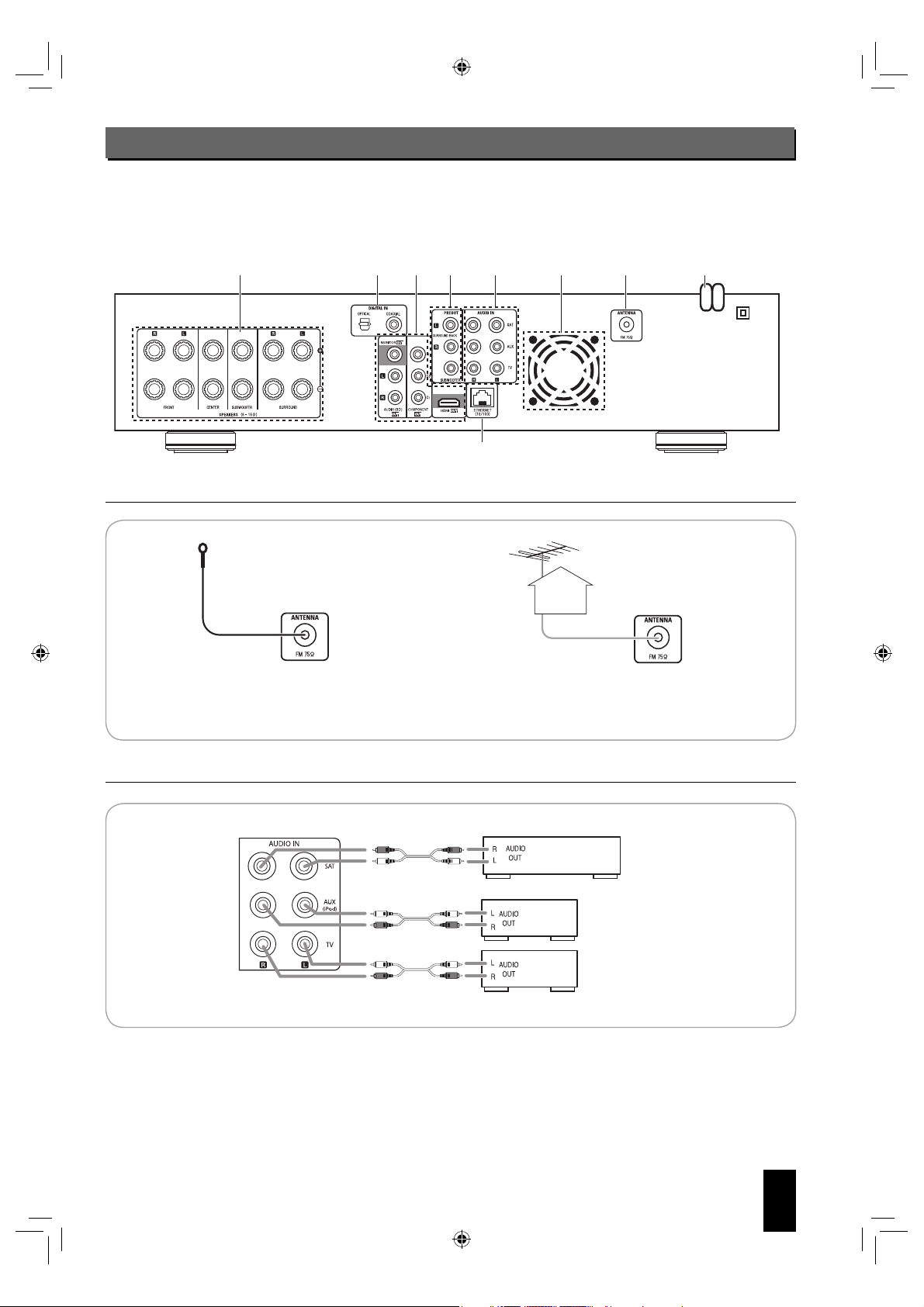
System Connections
SAT Satellite system, DVD player, etc.
AUX CD player, iPod, etc.
TV TV, tape deck, etc.
• Please be certain that this unit is unplugged from the AC outlet before making any connections.
• Since different components often have different terminal names, carefully read the operating instructions of the component
connected.
• Be sure to observe the color coding when connecting audio, video and speaker cords.
• Make connections firmly and correctly. If not, it can cause loss of sound, noise or damage to this unit.
54362
CONNECTING ANTENNAS
1.
FM Indoor Antenna FM Outdoor Antenna
• Change the position of the FM indoor antenna until you
get the best reception of your favorite FM stations.
81 9
7
• A 75Ω outdoor FM antenna may be used to further
improve the reception. Disconnect the indoor antenna
before replacing it with the outdoor one.
CONNECTING AUDIO/VIDEO COMPONENTS
2.
Satellite system, DVD player, etc.
CD player, iPod, etc.
TV, tape deck, etc.
• The AUDIO IN jacks can be connected to the AUDIO OUT jacks of audio or video components.
English
5
BDR-A7_EN_CS3.indb 5BDR-A7_EN_CS3.indb 5 11.3.10 6:59:34 PM11.3.10 6:59:34 PM
Page 6

CONNECTING TV
3.
• There are two types of video jacks (COMPONENT, (composite) VIDEO) for analog
video connections and the HDMI connector for digital video and audio connections.
Connect them to the corresponding video jacks according to their capability.
• For your reference, the excellence in picture quality is as follows : “HDMI” >
“COMPONENT” > “(composite) VIDEO” .
• When making COMPONENT VIDEO connections, connect “Y” to “Y”, “Cb” to “Cb”
(or “B-Y”, “P
• To hear the sound that the BD player reproduces from the speakers of your TV,
connect the AUDIO OUT jacks to the AUDIO IN jacks of the TV.
Notes :
■
• You don’t need to make all kinds of video connections between this unit and your
TV.
• Do not connect the unit to the TV through a VCR. Otherwise the picture may be
disturbed due to the copy protection function.
• If the resolutions of the video signals which are output from the COMPONENT
VIDEO OUTs and the HDMI OUT and your TV are not matched, the picture is
not clear, natural or displayed. To prevent it, you should set the resolution to one
which the TV can handle. (For details, refer to “Video output resolution” below and
“SETTING THE DISPLAY” on page 42.)
• To output the digital audio signals from the HDMI OUT to hear the sound that the
BD player reproduces from the speakers of your TV, you should set the HDMI
Output to On (Auto). (For details, refer to “SETTING THE AUDIO” on page 43.)
• For stable signal transfer, we recommend using HDMI cords that are a maximum of
5 meters in length.
• Among the components that support HDMI, some components can control other
components via the HDMI connector. However, this unit cannot be controlled by
another component via the HDMI connector.
• The audio signals from the HDMI connector (including the sampling frequency and
bit length) may be limited by the component that is connected.
Copyright protection system
■
• This unit supports HDCP (High-bandwidth Digital Contents Protection), technology to protect copyright of digital video
signals against illegal duplication. HDCP must also be supported on the components connected to this unit.
• This unit is HDMI Ver. 1.3 compatible.
• HDMI, the HDMI logo and High-Definition Multimedia Interface are trademarks or registered trademarks of HDMI licensing
LLC.
Video output resolution
■
• The video output resolution differs depending on the Resolution setting.
(For details, refer to “SETTING THE DISPLAY” on page 42.)
B
”) and “Cr” to “Cr”(or “R-Y”, “PR”).
MONITOR TV, Projector, etc.
Resolution setting
HDMI Auto 480i(NTSC)(or 576i(PAL)) 1080i
1080p 480i(NTSC)(or 576i(PAL)) 1080i
1080i 480i(NTSC)(or 576i(PAL)) 1080i
720p 480i(NTSC)(or 576i(PAL)) 720p
480p 480i(NTSC)(or 576i(PAL)) 480p(NTSC)(or 576p(PAL)) 480p(NTSC)(or 576p(PAL))
480i 480i(NTSC)(or 576i(PAL)) 480i(NTSC)(or 576i(PAL)) 480i(NTSC)(or 576i(PAL))
*1
: • When the COMPONENT OUTs and the HDMI OUT are connected to your TV, the video signals of 480i(NTSC)(or
576i(PAL)) will be output.
*2
: • When the HDMI OUT is not connected to your TV and the copy protected DVD Videos are played, the video signals of
480p(or 576p) will be output.
Notes :
■
• If the resolution of video signal to be output from COMPONENT OUTs or HDMI OUT does not match that of your TV, the
picture is not clear, natural or displayed.
Should this happen, first make (composite) video connection between this unit and TV, and select the (composite) VIDEO
as an input source on the TV to display the setting menu, then set the Resolution correctly. (For details on the resolution
acceptable for your TV, refer to its operating instructions.)
• When the HDMI OUT connector is connected to your TV, the TV reports to this unit what resolutions it supports. Therefore,
if you set the Resolution to HDMI Auto, this unit outputs the video signals of the highest resolution acceptable for your TV.
In this case, you cannot select the resolution inacceptable for your TV.
English
6
(Composite) VIDEO OUT COMPONENT OUTs HDMI OUT
Video OUTs
*1,*2
*1,*2
*1,*2
*1,*2
highest resolution
1080p
1080i
720p
BDR-A7_EN_CS3.indb 6BDR-A7_EN_CS3.indb 6 11.3.10 6:59:34 PM11.3.10 6:59:34 PM
Page 7
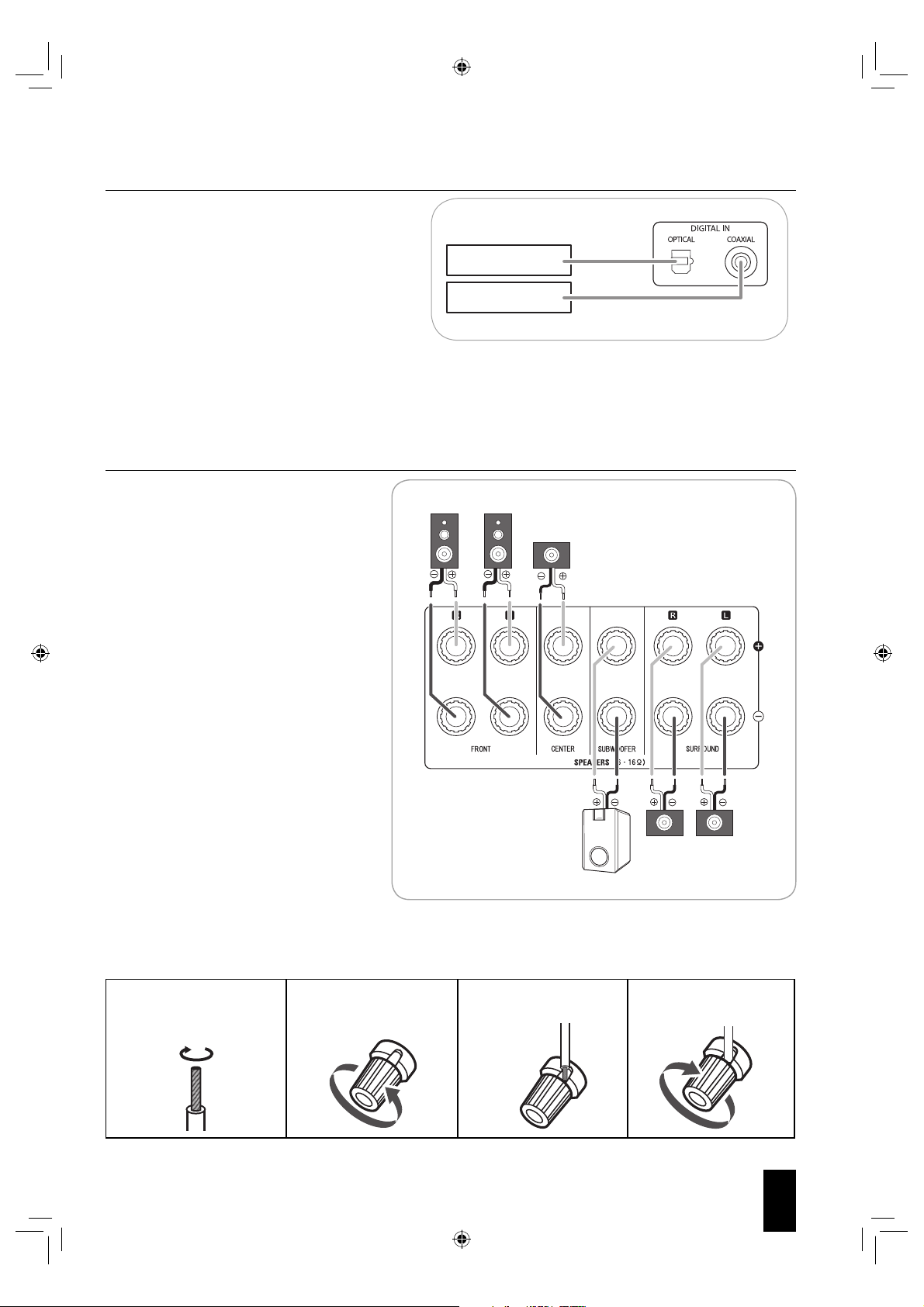
CONNECTING DIGITAL INs
Passive subwoofer
4.
• The OPTICAL and the COAXIAL DIGITAL OUTs of
the components that are connected to this unit can be
connected to these DIGITAL INs.
• A digital input should be connected to the components
such as a CD player, DVD player, etc. capable of
outputting DTS Digital Surround, Dolby Digital or PCM
format digital signals, etc.
• When making the COAXIAL DIGITAL connection, be
Component with
OPTICAL DIGITAL OUT
Component with
COAXIAL DIGITAL OUT
sure to use a 75 Ω COAXIAL cord, not a conventional
AUDIO cord.
Notes :
■
• Be sure to make either a OPTICAL or a COAXIAL DIGITAL connection on each component. (You don’t need to do both.)
• If you connect the DIGITAL INs to your components, you should assign the DIGITAL INs correctly. (For details, refer to
“When SAT, TV, AUX is selected as an input source” on page 14.)
CONNECTING SPEAKERS
5.
• Be sure to connect speakers firmly and
correctly according to the channel (left
and right) and the polarity (+ and -). If the
connections are faulty, no sound will be
Front
right
Front
left
Center
heard from the speakers, and if the polarity
of the speaker connection is incorrect, the
sound will be unnatural and lack bass.
• For installing the speakers, refer to “Speaker
placement” on page 8.
• After installing the speakers, first adjust
the speaker settings according to your
environment and speaker layout. (For details,
refer to “Setting the speaker setup” on page
20.)
• Depending on whether the type of your
subwoofer is the passive subwoofer or active
(powered) subwoofer, connect it as follows :
* Connect the SUBWOOFER terminals to the
passive subwoofer.
* Connect the SUBWOOFER PREOUT jack
to the active subwoofer. (For details, refer to
“CONNECTING PREOUTs” below.)
Caution :
• Be sure to use the speakers with the
impedance of 6 ohms or above.
• Do not let the bare speaker wires touch each
other or any metal part of this unit. This could
Passive subwoofer
Surround
right
Surround
left
damage this unit and/or the speakers.
• Never touch the speaker terminals while the AC input cord is connected to the wall AC outlet. Doing so could result in
electric shocks.
Connecting speaker wire
■
1. Strip away approx. 10
mm (3/8 inch) of wire
insulation, then twist the
2. Loosen by turning
the speaker terminal
counter-clockwise.
3. Insert the bare part of
the wire.
4. Tighten by turning it
clockwise.
wire ends tight.
English
BDR-A7_EN_CS3.indb 7BDR-A7_EN_CS3.indb 7 11.3.10 6:59:34 PM11.3.10 6:59:34 PM
7
Page 8

CONNECTING PREOUTs
6.
• Use these jacks when adding additional speakers for
7.1 or 6.1 channel playback.
• Connect the SURROUND BACK PREOUT jacks to
the power amplifier connected to speakers.
• When using only one surround back speaker,
connect the SURROUND BACK Left jack to the
power amplifier.
• To emphasize the deep bass sounds, connect a
powered subwoofer to the SUBWOOFER PREOUT
jack.
Speaker placement
Ideal speaker placement varies depending on the size of
your room and the wall coverings, etc. The typical example of
speaker placement and recommendations are as follows :
Front left and right speakers and center speaker
■
• Place the front speakers with their front surfaces as flush
with TV or monitor screen as possible.
• Place the center speaker between the front left and right
speakers and no further from the listening position than the
front speakers.
• Place each speaker so that sound is aimed at the location
of the listener’s ears when at the main listening position.
Powered subwoofer
Power amplifier
Surround
back speakers
Surround left and right speakers
■
• Place the surround speakers approximately 1 meter (40
inches) above the ear level of a seated listener on the direct
left and right of them or slightly behind.
Surround back left and right speakers
■
• Place the surround back speakers at the back facing the
front at a narrower distance than front speakers.
• When using a single surround back speaker, place it at the
rear center facing the front at a slightly higher position (0 to
20 cm) than the surround speakers.
• We recommend installing the surround back speaker(s) at
a slightly downward facing angle. This effectively prevents
the surround back channel signals from reflecting off the TV
or screen at the front center, resulting in interference and
making the sense of movement from the front to the back
less sharp.
Subwoofer
■
• The subwoofer reproduces powerful deep bass sounds.
Place a subwoofer anywhere in the front as desired.
Notes :
■
• When using a conventional TV, to avoid interference with
the TV picture, use only magnetically shielded front
left and right and center speakers.
• To obtain the best surround effects, the speakers except the
subwoofer should be full range speakers.
1. TV or Screen
2. Front left speaker
3. Subwoofer
4. Center speaker
5. Front right speaker
6. Surround left speaker
Surround speaker
Front speaker
7. Surround right speaker
8. Surround back left speaker
9. Surround back right speaker
10. Surround center speaker
11. Listening position
Surround back
speaker
Point slightly
downward
English
8
BDR-A7_EN_CS3.indb 8BDR-A7_EN_CS3.indb 8 11.3.10 6:59:34 PM11.3.10 6:59:34 PM
Page 9

CONNECTING TO NETWORK
7.
• You can enjoy a variety of contents with interactive functions by connecting to the internet when playing BD-LIVE compatible
discs on the BD player.
• Connect the ETHRNET (10/100) connector of this unit to your internet source.
Broadband router PCModemInternet
Notes :
■
• After making a broadband internet connection, you should set the communication setting. (For details, refer to “SETTING
THE NETWORK” on page 45.)
• When using a broadband internet connection, a contract with an internet service provider is required. For more information,
contact your nearest internet service provider.
• Refer to the operating instructions of the equipment because the connected equipment and connection method may differ
depending on your internet environment.
• Use a LAN cable/router supporting 10 BASE-T/100 BASE-TX.
• Some LAN cables are easily affected by noise.
We recommend using a shield type cable.
COOLING FAN
8.
• Cooling fan operates to prevent the temperature inside this unit from rising. To allow for proper ventilation, maintain a certain
space behind this unit.
Note :
■
• While the fan is operating, the faint fan noise may be generated.
AC INPUT
9.
• Plug this cord into a wall AC outlet.
CAUTION (Notes on the AC power cord and the wall outlet)
¤
• The unit is not disconnected from the AC power source (mains) as long as it is connected to the wall outlet, even if the unit
has been turned off.
• To completely disconnect this product from the mains, disconnect the plug from the wall socket outlet.
• When setting up this product, make sure that the AC outlet you are using is easily accessible.
• Disconnect the plug from the wall outlet when not using the unit for long periods of time.
English
9
BDR-A7_EN_CS3.indb 9BDR-A7_EN_CS3.indb 9 11.3.10 6:59:34 PM11.3.10 6:59:34 PM
Page 10

Front Panel Controls
Media indicators
SLEEP indicator DIGITAL indicator TUNED indicator
MEMORY indicatorHDMI indicator STEREO indicator
RDS indicator
REPEAT indicatorsInput signal indicators
Dolby PLII/PLIIx indicators
Input, frequency, title/chapter/track number, playing time, volume level, operating information, etc.
RANDOM indicator
1. POWER ON/STANDBY button/indicator
2. PHONES jack
3. USB connector
For details, see below.
4. FLUORESCENT DISPLAY
For details, see below.
5. DISC TRAY
FLUORESCENT DISPLAY
■
Media indicators Input signal indicators
SLEEP indicator
HDMI indicator
Input, frequency, title/chapter/track number, playing time, volume level, operating information, etc.
6. REMOTE SENSOR
7. INPUT SELECTOR button
8. VOLUME CONTROL knob
9. OPEN/CLOSE (
10. PLAY/PAUSE (
11. STOP (
12. FORWARD/BACKWARD SKIP(
DIGITAL indicator
MEMORY indicator STEREO indicator
) button
Dolby PLII/PLIIx indicators
TUNED indicator
) button
) button
/ ) buttons.
REPEAT indicators
RDS indicator
RANDOM indicator
USB CONNECTOR
■
• This connector can be connected to a USB memory device for playback of MP3, WMA
or JPEG files, etc. stored on it. (For details, refer to “PLAYING FILES” on page 35.)
• To enjoy BONUSVIEW and BD-LIVE functions, you can connect a USB memory device
(minimum 1GB capacity (2GB or more recommended)) supporting FAT 32 and USB
2.0 High Speed (480 Mbit/s) to this connector, too. (For details, refer to “ENJOYING
BONUSVIEW OR BD-LIVE” on page 34.)
Notes :
BDR-A7_EN_CS3.indb 10BDR-A7_EN_CS3.indb 10 11.3.10 6:59:34 PM11.3.10 6:59:34 PM
■
• Do not use a USB extension cable when connecting a USB memory device to this
connector.
• After playback of files or Virtual Package/BD-LIVE data, remove the USB memory
device in the stop mode or the standby mode.
English
10
Page 11

Universal Remote Controls
2
1
3
5
4
6
7
8
This universal remote control can operate not only this unit but also most popular brands of video components such as TVs,
cable boxes, satellite receivers, etc.
• To operate 3 components other than this unit, you should enter the setup code for each component.
(For details, refer to “ENTERING A SETUP CODE” on page 12.)
• The numbered buttons on the remote control have different functions in other device modes. For details, refer to
“FUNCTION TABLE of the NUMBERED BUTTONS” on the next page.
LED
POWER ON button
STANDBY button
To operate the desired component
with this remote control, first select the
corresponding DEVICE button
.
INPUT SELECTOR buttons
STEREO button
DEVICE buttons
MUTE button
REPEAT A-B button
SURROUND MODE UP/DOWN(>/<)
buttons
VOLUME %/fi buttons
REPEAT button
SUBTITLE button
AUDIO button
SPEAKER SETUP button
DISPLAY button
ANGLE button
COLOR buttons
HOME MENU button
DISC MENU button
CURSOR CONTROL, OK (/
SEARCH MODE, SELECT〈, 〉)
RETURN button
PLAY button
STOP button
TUNING UP/DOWN (+/-),
FORWARD/BACKWARD
SEARCH( / ) buttons
NUMERIC buttons
buttons
The function in “( )” are regional option
for Europe, etc.
POP UP MENU button
PAUSE (
) button
STEP( ) button
PRESET UP/DOWN(+/-),
FORWARD/BACKWARD
SKIP( / ) buttons
DIMMER button
SLEEP button
RANDOM button
GO TO button
PIP button
CLEAR button
Note :
■
• You can use the COLOR buttons to select the items on some BD menus during operation of BD player.
Standby mode
■
While the STANDBY indicator is lit, a small amount of power is supplied to the system to back up the memory. This is called
standby mode. Under the condition, the system can be turned ON by the remote control unit.
English
BDR-A7_EN_CS3.indb 11BDR-A7_EN_CS3.indb 11 11.3.10 6:59:35 PM11.3.10 6:59:35 PM
11
Page 12

FUNCTION TABLE of the NUMBERED BUTTONS.
■
Device to be
controlled
Button symbol
1
2
3 MUTE MUTE MUTE
(for TV) (for Cable box)
POWER ON POWER ON POWER ON
STANDBY STANDBY STANDBY
(for Satellite
receiver)
Notes :
■
• Some functions for each component may not
be available or may work differently.
• Depending on other kinds of components that
are available for each DEVICE button, some
functions may not be available or may work
differently, too.
• For details about functions, refer to the
operating instructions of each component.
4
5
6
7
8
CHANNEL UP CHANNEL UP CHANNEL UP
CHANNEL DOWN CHANNEL DOWN CHANNEL DOWN
VOLUME %/
INPUT
SELECTOR
NUMERIC NUMERIC NUMERIC
fi
VOLUME %/
INPUT
SELECTOR
fi
VOLUME %/
INPUT
SELECTOR
fi
ENTERING A SETUP CODE
• This remote control can control up to 3 different components.
• Before operating video components other than this unit with using this remote control, the setup code for each
component should be entered.
1.
Turn on the component you want to operate.
2.
Find the setup codes according to the type and the
brand name of your component, referring to “Setup
Code Table” on page 54.
3.
Press and hold down both the OK button and the
DEVICE button you want for more than 1 seconds.
4.
Enter a 3 digit code.
Example: When entering “001”.
• If entering is performed successfully, the LED will flicker
twice.
: For TV
: For cable box
: For satellite receiver
• The LED will flicker once.
Note :
■
• The MAIN button is unavailable for the components other
than this unit.
• To be sure that the setup code is correct, press the ON (or
STANDBY) button, aiming the remote control at the remote
sensor on the component. If your component is turned off,
the setup code is correct.
• When your component is not turned off, repeat the above
steps 2 to 4, trying each code for your component until you
find one that works.
Notes :
■
• If the LED did not flicker twice, then repeat the above steps
3 to 4 and try entering the same code again.
• Manufacturers may use different setup codes for the same
product category. For that reason, it is important that you
check to see if the code you have entered operates as
many controls as possible. If only a few functions operate,
check to see if another code will work with more buttons.
5.
Repeat the above steps 1 to 4 for each of your
components.
English
12
BDR-A7_EN_CS3.indb 12BDR-A7_EN_CS3.indb 12 11.3.10 6:59:35 PM11.3.10 6:59:35 PM
Page 13
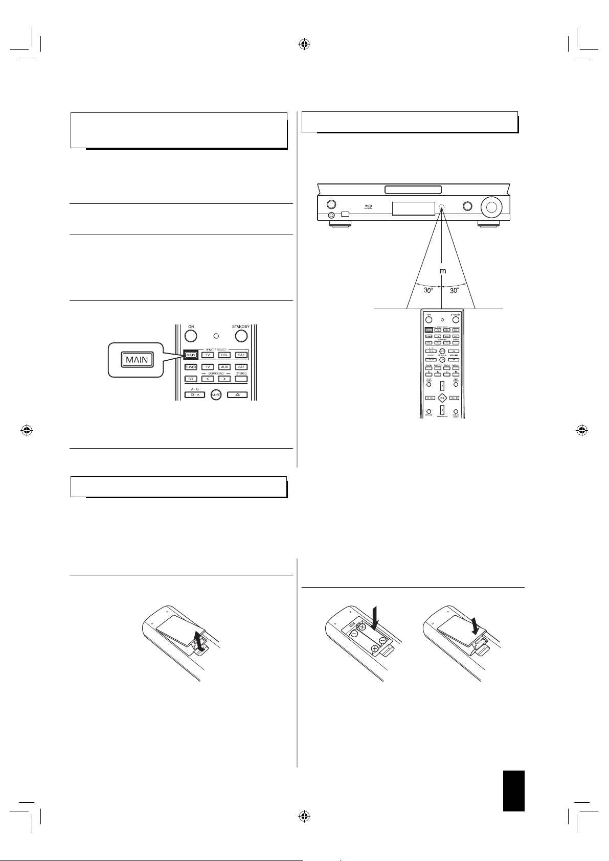
OPERATING COMPONENTS WITH REMOTE
CONTROL
1.
Enter the setup code for each component other
than this unit you wish to control. (For details, refer
to “ENTERING A SETUP CODE” on page 12.)
2.
Turn on the component you want to operate.
3.
Press the DEVICE button on the remote control
corresponding to the component you wish to
operate.
Example) When selecting “MAIN” to operate this unit.
4.
Aim the remote control at the REMOTE SENSOR
of the component you wish to control and press the
button corresponding to the operation you want.
REMOTE CONTROL OPERATION RANGE
• Use the remote control within a range of about 7 meters (23
feet) and angles of up to 30 degrees aiming at the remote
sensor.
7
Note :
■
• Remote operation may become unreliable if the remote
sensor is exposed to strong light such as direct sunlight or
inverted fluorescent.
LOADING BATTERIES
• When the remote control does not operate, the old batteries should be replaced. In this case, load new batteries within
several minutes after removing old batteries.
• If the batteries are removed or have been exhausted for a longer period of time, memorized contents will be cleared.
Should this happen, you should memorize them again.
1.
Remove the cover.
CAUTION
¤
• Do not leave the battery near fire or under direct sunlight.
• A fire, explosion or excessive heat generation may result.
2.
Load two batteries (AAA size, LR03/24A) matching
the polarity.
• Remove the batteries when they are not used for a long
time.
• Do not use the rechargeable batteries (Ni-Cd type).
• Be sure to use alkaline batteries.
English
13
BDR-A7_EN_CS3.indb 13BDR-A7_EN_CS3.indb 13 11.3.10 6:59:35 PM11.3.10 6:59:35 PM
Page 14

Basic Operation
Notes :
■
• Before operating this receiver with the supplied remote control, refer to “Universal Remote Controls” on page 11 for
details about operation.
• Before operating this receiver, first set this unit as desired for optimum performance, doing the setup procedures. (For
details, refer to “SYSTEM SETUP” on page 18.)
LISTENING TO A PROGRAM SOURCE
1.
Turn the power on.
or
• Each time the POWER ON/STANDBY button is pressed,
the unit is turned on to enter the operating mode (the
POWER ON/STANDBY indicator lights up blue) or off
to enter the standby mode (the POWER ON/STANDBY
indicator lights up amber).
• On the remote control, press the ON button to enter the
operating mode or press the STANDBY button to enter
the standby mode.
Standby mode
■
This means that the unit is not disconnected from the
AC mains and a small amount of current is retained to
support the operation readiness.
2.
Select the desired input source.
or
• Each time the INPUT SELECTOR button on the front
panel, the input source changes as follows :
FM ➝ SAT ➝ TV ➝ AUX ➝ BD/DVD
(frequency display)
• Each time this button is pressed, the corresponding
input is selected as follows :
ANLG(Analog) ➝ COAX(Coaxial) ➝ OPTI(Optical)
Note :
■
• When the selected digital input is not connected, the
“DIGITAL” indicator flickers and the analog input is
automatically selected.
4.
Operate the selected component for playback.
• When playing back the program sources with surround
sound, refer to “ENJOYING SURROUND SOUND” on
page 17.
5.
Adjust the (overall) volume to a comfortable
listening level.
or
6.
To mute the sound.
• Each time the “TUNER” button on the remote control is
pressed, the FM mode changes as follows :
FM ST ➝ FM MONO
Note :
■
• During playback of BD Video or DVD Video on the BD
player, if an input source is selected and then BD/DVD is
selected within 3 minutes again, playback will be paused
on that point at which an input source is selected.
• “MUTE” is displayed.
• To resume the previous sound level, press it again.
7.
To listen with the headphones.
When SAT, TV, AUX is selected as an input
source
3.
Select the digital or analog input connected as
desired.
English
14
BDR-A7_EN_CS3.indb 14BDR-A7_EN_CS3.indb 14 11.3.10 6:59:35 PM11.3.10 6:59:35 PM
• Then the “SPK OFF” is displayed and the sound from
the speakers is cut off.
CAUTION
¤
• A warning that excessive sound pressure from
earphones and headphones can cause hearing loss.
Page 15
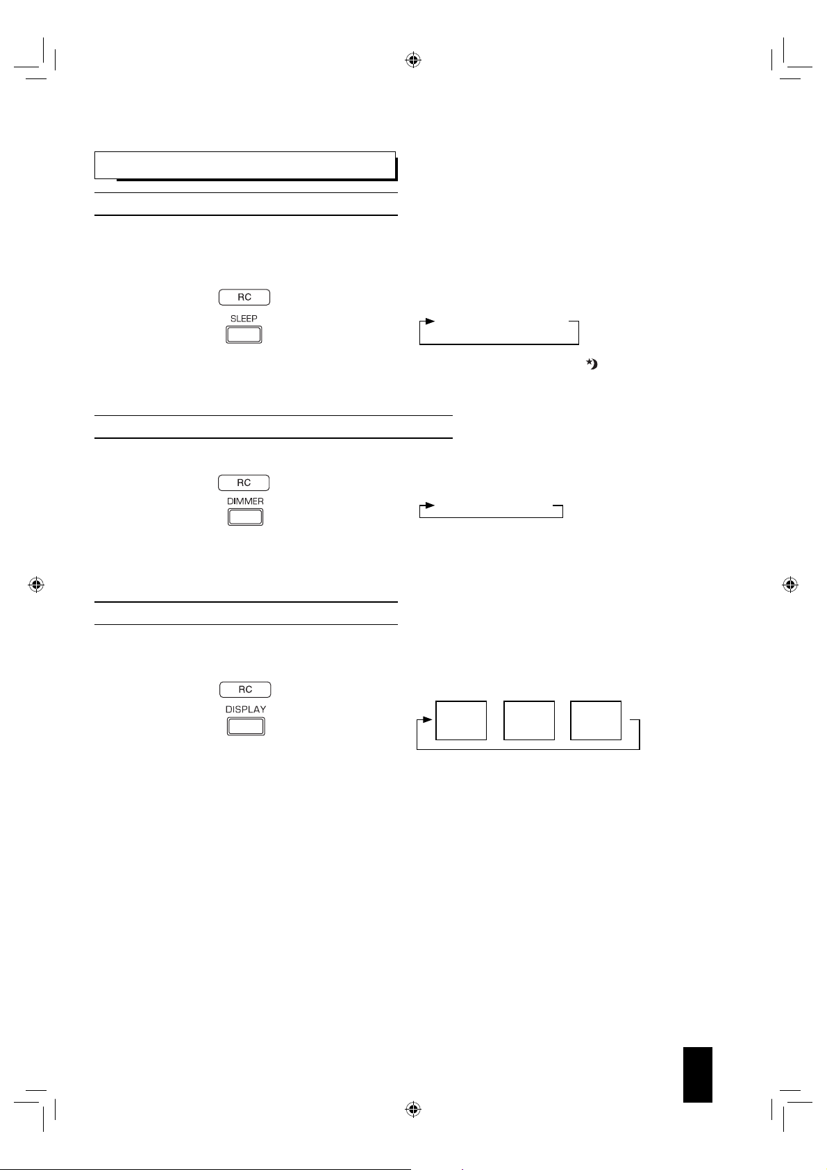
OTHER FUNCTIONS
Operating the sleep timer
• The sleep timer allows the system to continue to operate for a specified period of time before automatically shutting off.
• To set the receiver to automatically turn off after the specified period of time.
• Each time this button is pressed, the sleep time changes as
follows:
• While operating the sleep timer, “ ” lights up.
• When the sleep time is selected, the fluorescent display is
Adjusting the brightness of the fluorescent display
• Each time this button is pressed, the brightness of the
• In the display OFF mode, if some buttons are pressed, the
Displaying the operation status
During playback,
• Each time this button is pressed, the display mode changes
30 ➝ 60 ➝ 90 ➝ OFF
dimly lit.
fluorescent display changes as follows:
ON ➝ dimmer ➝ OFF
display OFF mode may be canceled for several seconds
depending on operation status.
as follows:
Surround
mode
Unit : minutes
➝➝
Volume
source
Input
• When the BD/DVD is selected as an input source, see
“Displaying disc information” on page 30 and “Displaying file
information” on page 37.
• When Radio Data System tuner function is available in
your country, for details on the FM mode information, see
“Displaying Radio Data System information” on page 49.
English
BDR-A7_EN_CS3.indb 15BDR-A7_EN_CS3.indb 15 11.3.10 6:59:36 PM11.3.10 6:59:36 PM
15
Page 16

SURROUND SOUND
• This receiver incorporates a sophisticated Digital Signal Processor that allows you to create optimum sound quality and
sound atmosphere in your personal Home Theater.
Surround modes
DTS Digital Surround
■
DTS Digital Surround (also called simply DTS) supports up
to 5.1 discrete channels and uses less compression for high
fidelity reproduction. Use it with DVDs and CDs bearing the
DTS logo.
DTS-HD High Resolution Audio
■
Developed for use with HDTV, including the new video disc
formats Blu-ray and HD DVD, this is the latest multi-channel
audio format from DTS. It supports up to 5.1 channels with
96 kHz/24 bit sampling rate and signal resolution.
DTS-HD Master Audio
■
Designed to take full advantage of the additional storage
space offered by the new Blu-ray and HD DVD disc formats,
this new DTS format offers up to 5.1 discrete channels of
uncompressed digital audio with 96 kHz/24 bit sampling rate
and signal resolution.
Manufactured under license under U.S. Patent #’s: 5,451,942;
5,956,674; 5,974,380; 5,978,762; 6,226,616; 6,487,535; 7,392,195;
7,272,567; 7,333,929; 7,212,872 & other U.S. and worldwide patents
issued & pending. DTS and the Symbol are registered trademarks,
& DTS-HD, DTS-HD Master Audio | Essential and the DTS logos are
trademarks of DTS, Inc. Product includes software. © DTS, Inc. All
Rights Reserved.
Dolby Digital
■
Dolby Digital is the multi-channel digital signal format
developed by Dolby Laboratories. Discs bearing the Dolby
Digital logo includes the recording of up to 5.1 channels of
digital signals. This will put you right in the middle of the
action, just like being in a movie theater or concert hall.
Dolby Digital EX
■
This mode expands 5.1-channel sources for 6.1/7.1
channel playback. It’s especially suited to Dolby Digital EX
soundtracks that include a matrix-encoded surround back
channel. The additional channel adds an extra dimension and
provides an enveloping surround sound experience, perfect
for rotating and fly-by sound effects.
Dolby Digital Plus
■
Developed for use with HDTV, including the new video disc
formats Blu-ray and HD DVD, this is the latest multichannel
audio format from Dolby. It supports up to 7.1 channels with
48 kHz/24-bit sampling rate and signal resolution.
Dolby TrueHD
■
Designed to take full advantage of the additional storage
space offered by the new Blu-ray and HD DVD disc formats,
this new Dolby format offers up to 7.1 discrete channels of
lossless audio performance with 96 kHz/24 bit sampling rate
and signal resolution.
16
English
Dolby Pro Logic IIx surround
■
This mode expands any 2-channel source for 7.1-channel
playback. It provides a very natural and seamless surround
sound experience that fully envelopes the listener. As well
as music and movies, video games can also benefit from the
dramatic spatial effects and vivid imaging. It includes “Dolby
Pro Logic IIx Movie” suited for playing movies, “Dolby Pro
Logic IIx Music” suited for playing music and “Dolby Pro Logic
IIx Game” suited for playing games.
Dolby Pro Logic II surround
■
If you are not using any surround back speakers, Dolby Pro
Logic II surround will be used instead of Dolby Pro Logic IIx
surround. It includes Dolby Pro Logic II Movie, Dolby Pro
Logic II Music and Dolby Pro Logic II Game like Dolby Pro
Logic IIx surround.
Dolby Pro Logic
■
This mode expands any 2-channel source (, including Dolby
Surround source) for 4 channel (front left, center, front right
and surround) playback. The surround channel is monaural,
but is played through two surround speakers.
Manufactured under license from Dolby Laboratories.
Dolby, Pro Logic, and the double-D symbol are registered trademarks
of Dolby Laboratories.
BDR-A7_EN_CS3.indb 16BDR-A7_EN_CS3.indb 16 11.3.10 6:59:36 PM11.3.10 6:59:36 PM
Page 17

• The following modes apply conventional 2-channel signals
such as digital PCM or analog stereo signals to high
performance Digital Signal Processor to recreate sound
fields artificially. Select one of the 7 provided surround
modes according to the program source you want to play.
Movie
■
This mode provides the effect of being in a movie theater
when watching a action movies with dynamic soundtracks.
Drama
■
This mode is suitable for movies with lots of dialog.
Game
■
This mode is suitable for video games.
Stadium
■
This mode provides the expansive sound field to achieve the
true stadium effect when watching baseball or soccer games.
Classic
■
This mode provides the acoustic effects of a large concert
hall for classical music.
Hall
■
This mode provides the ambience of a concert hall for rock or
pop music.
MULTI CH Stereo
■
This mode is for enjoying stereo sound from all speakers.
ENJOYING SURROUND SOUND
Notes:
■
• Before surround playback, first perform the speaker setup procedure, etc. on the SETUP menu for optimum
performance. (For details, refer to “Setting the speaker setup” on page 20.)
• Select the desired surround mode.
• Press the SURROUND MODE UP/DOWN (>/<) buttons to select a surround mode or
press the STEREO button to select the stereo mode.
• Each time the SURROUND MODE UP/DOWN (>/<) buttons are pressed, the surround
mode changes as follows :
Auto surround mode :
Manual surround mode :
• Depending on the input source you select, the surround modes are selected as follows :
When selecting an input source other than BD/DVD
■
Signal format being input Selectable surround mode
Dolby Digital EX 6.1 channel sources AUTO SURROUND, corresponding DOLBY mode, STEREO
Dolby Digital 5.1 channel sources AUTO SURROUND, <DOLBY DIGITAL EX, DOLBY D+PLIIx MUSIC>, (DOLBY D+ PLIIx MOVIE),
Dolby Digital 2 channel sources AUTO SURROUND, <DOLBY PLIIx MOVIE, DOLBY PLIIx MUSIC, DOLBY PLIIx GAME>, [DOLBY
DTS ES Discrete 6.1 channel sources,
DTS ES Matrix 6.1 channel sources,
DTS 96/24 sources
DTS sources AUTO SURROUND, <DTS+PLIIx MUSIC>, (DTS+PLIIx MOVIE), [DTS], STEREO
PCM 2 channel sources,
PCM multi-channel sources,
Analog stereo sources,
When selecting the BD/DVD
■
Signal format being input Selectable surround mode
Dolby Digital Plus sources, Dolby TrueHD sources,
Dolby Digital EX 6.1 channel sources,
Dolby Digital 5.1 channel sources,
DTS-HD High Resolution Audio sources,
DTS-HD Master Audio sources,
DTS ES Discrete 6.1 channel sources,
DTS ES Matrix 6.1 channel sources,
DTS 96/24 sources,
DTS sources,
PCM multi-channel sources,
PCM 2 channel sources,
Dolby Digital 2 channel sources
• Depending on surround back speaker setting, some surround modes can be selected or not as follows:
< >: Possible only when surround back speaker is not set to “NO”.
[ ] : Possible only when surround back speaker is set to “NO”.
( ) : Possible only when surround back speaker is set to “X2”.
Note:
■
[DOLBY DIGITAL], STEREO
PLII MOVIE, DOLBY PLII MUSIC, DOLBY PLII GAME], DOLBY PRO LOGIC, STEREO
AUTO SURROUND, corresponding DTS mode, STEREO
AUTO SURROUND, <DOLBY PLIIx MOVIE, DOLBY PLIIx MUSIC, DOLBY PLIIx GAME>, [DOLBY
PLII MOVIE, DOLBY PLII MUSIC, DOLBY PLII GAME], DOLBY PRO LOGIC, MOVIE, DRAMA,
GAME, STADIUM, CLASSIC, HALL, MULTI CH STEREO, STEREO
AUTO SURROUND, MOVIE, DRAMA, GAME, STADIUM, CLASSIC, HALL,
MULTI CH STEREO, STEREO
• When listening with the headphones, only the stereo mode can be selected.
The truest possible playback mode will be automatically
selected according to the number of channels in the signal
being input.
You can select the desired of different surround modes
selectable for the signal being input.
English
17
BDR-A7_EN_CS3.indb 17BDR-A7_EN_CS3.indb 17 11.3.10 6:59:36 PM11.3.10 6:59:36 PM
Page 18

SYSTEM SETUP
• The setup menu is displayed on the fluorescent display and allows you to perform the setup procedures easily. In most
situations, you will only need to set this once during the installation and layout of your home theater, and it rarely needs to
be changed later.
1.
Turn the setup menu on.
• “SOUND PRMT” will be shown.
• To turn the menu off, press this button again.
• When the RETURN is pressed on a sub-menu, it will returns
to the previous menu.
2.
Select the desired menu using the CURSOR UP/DOWN buttons.
• Each time these buttons are pressed, the setup menu is
selected as follows :
“SOUND PRMT” ↔ “TONE” ↔ “SPK SET”
(Sound Parameter) (Speaker Setup)
• When “TONE” is selected, see “Setting the Tone” on page
23.
3.
When selecting the “SOUND PRMT” or the “SPK SET”, press the OK button to enter it’s setup menu.
• When “SPK SET” is selected, see “Setting the speaker
setup” on page 20.
• When “SOUND PRMT” is selected, see “Setting the sound
parameter” below.
Setting the sound parameter
• You can adjust the different sound parameters for optimum surround effect.
• Settings with* are the default.
SOUND PRMT
1.
Press the CURSOR UP/DOWN buttons to select the desired parameter.
L.SYNC 0* / 0 ~ 9.0
D.M. CH1* / CH2 / CH1+2
DRC OFF* / MID / MAX
LFE 0 dB* / -10 / OFF
C.WIDTH 3* / 0 ~ 7
DIMEN 0* / -3 ~ +3
PNRM OFF* / ON
Notes :
■
• “C.WIDTH”, “DIMEN” and “PNRM” can be selected only while listening in Dolby Pro Logic II Music or Dolby Pro Logic IIx
Music mode.
• “D.M.” and “DRC” settings are not valid when BD/DVD is selected as an input source.
English
18
BDR-A7_EN_CS3.indb 18BDR-A7_EN_CS3.indb 18 11.3.10 6:59:36 PM11.3.10 6:59:36 PM
Page 19

2.
Press the CURSOR LEFT/RIGHT buttons to adjust the selected parameter as desired.
3.
Repeat the above steps 1 and 2 to adjust other parameter.
When selecting the “L.SYNC (Lip-Sync)”
■
• There may be a slight time delay between the video and audio signals in case that some video playback equipment may
process the video signals later than the audio signals due to signal processing procedure, etc.. Should this happen, you can
adjust the time delay of audio signals to synchronize the sound with the picture.
• The time delay can be adjusted with the range of 0.0 ~ 9.0 frames (1 sec. = 30 frames).
When selecting the “D.M. (Dual Mono)”
■
• Dual mono software usually is used to put two different mono soundtracks, that you can listen to together or separately, on
one DVD, etc. With this setting you can choose which dual mono setting you want to listen to.
• This setting works only with dual mono encoded Dolby Digital and DTS soundtracks.
CH 1 : Only channel 1 is heard from the front speakers.
↕
CH 2 : Only channel 2 is heard.
↕
CH 1+2 : Both channels are heard.
When selecting the “DRC (Dynamic Range Control)”
■
• This function compresses the dynamic range of previously specified parts of Dolby Digital or DTS sound track (with
extremely high volume) to minimize the difference in volume between the specified and non-specified parts. This makes it
easy to hear all of the sound track when watching movies at night at low levels.
OFF : To turn the DRC function off.
↕
MID : To adjust it to “MID” level.
↕
MAX : To adjust it to “MAX” level.
Note :
■
• In some Dolby Digital or DTS software, the DRC setting may not be valid.
When selecting the “LFE (LFE level)”
■
• Some Dolby Digital or DTS source, etc. includes LFE (ultra low bass) signals.
• The LFE level can be adjusted as desired.
OFF : To output no sound from the LFE channel.
↕
0 : In general, to set to 0dB (recommended value)
↕
-10: To set to -10 dB for some early DTS software, etc.
When selecting the “C.WIDTH (Center Width)”
■
• This adjusts the center image so it may be heard only from the center speaker, only from left/right speakers as a phantom
image, or from all three front speakers to varying degrees.
• The control can be set in 8 steps from 0 to 7.
Note :
■
• This control valid only when the center speaker is not set to NO.
When selecting the “DIMEN (Dimension)”
■
• This gradually adjusts the sound field either towards the front or towards the rear. The control can be set in 7 steps from -3
to +3.
When selecting the “PNRM (Panorama)”
■
• This mode extends the front stereo image to include the surround speakers for an exciting “wraparound” effect with side wall
imaging. Select “OFF” or “ON”.
English
BDR-A7_EN_CS3.indb 19BDR-A7_EN_CS3.indb 19 11.3.10 6:59:36 PM11.3.10 6:59:36 PM
19
Page 20

Setting the speaker setup
• After you have installed this receiver and connected all the components, you should adjust the speaker settings for the
optimum sound acoustic according to your environment and speaker layout.
• Even when you change speakers, speaker positions, or the layout of your listening environment, you should
adjust the speaker settings, too.
• Settings with* are the default.
SPK CFG
X OVER X OVER 50 / 80 / 100* / 150 / 200
CH LEVEL
DISTANCE
F LARGE* / SMALL
C LARGE* / SMALL / NO
S LARGE* / SMALL / NO
SB LX2 / LX1 / SX2 / SX1 / NO*
SW YES* / PLUS / NO
T TONE M* / A
L 3.0 M* / 0.1 ~ 9.0
C 3.0 M* / 0.1 ~ 9.0
R 3.0 M* / 0.1 ~ 9.0
SR 3.0 M* / 0.1 ~ 9.0
SBR 3.0 M* / 0.1 ~ 9.0
SBL 3.0 M* / 0.1 ~ 9.0
SL 3.0 M* / 0.1 ~ 9.0
SW 3.0 M* / 0.1 ~ 9.0
L 0 dB* / -15 ~ +15
C 0 dB* / -15 ~ +15
R 0 dB* / -15 ~ +15
SR 0 dB* / -15 ~ +15
SBR 0 dB* / -15 ~ +15
SBL 0 dB* / -15 ~ +15
SL 0 dB* / -15 ~ +15
SW 0 dB* / -15 ~ +15
• SPK CFG (SPEAKER CONFIGURATION) : To adjust the speakers depending on whether they are connected or not.
• X OVER (CROSSOVER FREQUENCY) : To select the desired crossover frequency.
• CH (CHANNEL) LEVEL : To adjust each channel level with the test tone.
• DISTANCE (SPEAKER DISTANCE) : To select the distance between the listening position and each speaker to
set the delay time automatically for optimum surround playback.
English
20
BDR-A7_EN_CS3.indb 20BDR-A7_EN_CS3.indb 20 11.3.10 6:59:36 PM11.3.10 6:59:36 PM
Page 21

When selecting the SPEAKER CONFIGURATION
■
1.
Press the CURSOR UP/DOWN buttons to select the “SPK CFG”, then press the OK button.
• Then “F ~” will be displayed.
2.
Press the CURSOR UP/DOWN buttons to select the desired speaker.
3.
Press the CURSOR LEFT/RIGHT buttons to set the selected speaker as desired.
• Depending on your speaker type, you can select one of these following speaker types.
• Front, Center, Surround and Surround Back speakers :
LARGE (or L) : Select this when connecting speakers that can fully reproduce sounds below crossover frequency.
SMALL (or S) : Select this when connecting speakers that can not fully reproduce sounds below crossover frequency.
When this is selected, sounds below crossover frequency are sent to the subwoofer or speakers which
are set to “LARGE” (when not using a subwoofer).
NO : Select this when no speakers are connected. When this is selected, sounds are sent to the speakers which are
not set to “NO”.
( ) : Selectable for Surround Back speakers.
• Surround Back speakers :
X2/X1 : Select the desired depending on the number of speakers connected to SURROUND BACK/PREOUTs.
• SubWoofer :
YES : Select this to output LFE signals and bass frequencies of channels set to “SMALL” from the subwoofer.
PLUS : Select this if you want the subwoofer to output bass sound continuously or you want deeper bass (the bass
frequencies that would normally come out the front and center speakers are also routed to the subwoofer.)
NO : Select this when the subwoofer is not connected. The bass frequencies are output from other speakers.
Notes :
■
• When speakers are set to “SMALL”, you should set their crossover frequency correctly according to their frequency
characteristics. (For details, refer to “When selecting the CROSSOVER FREQUENCY” on page 22.)
• When the “F” (Front) is set to “SMALL, “C” (Center), “S” (Surround) and “SB” (Surround Back) cannot be set to “LARGE”
and the “SW” (SubWoofer) cannot be set to “PLUS” or “NO”.
• When the “S” (Surround) is set to “SMALL”, the “SB” (Surround Back) cannot be set to “L” (Large).
4.
Repeat the above steps 2 and 3 until the speakers are all set to the desired mode.
About the speaker size
■
• Select “LARGE” or “SMALL” not according to the actual size of the speaker but according to the speaker’s capacity for
playing low frequency (bass sound below frequency set on the “CROSSOVER FREQUENCY” menu) signals.
• If you do not know, try comparing the sound at both settings (setting the volume to a level low enough so as not to
damage the speakers) to determine the proper setting.
English
BDR-A7_EN_CS3.indb 21BDR-A7_EN_CS3.indb 21 11.3.10 6:59:36 PM11.3.10 6:59:36 PM
21
Page 22

When selecting the CROSSOVER FREQUENCY
■
1.
Press the CURSOR UP/DOWN buttons to select the “X OVER”, then press the OK button.
• Then “X OVER ~” will be displayed.
2.
Press the CURSOR LEFT/RIGHT buttons to set the crossover frequency as desired.
• You can select the crossover frequency among 50, 80, 100, 150 and 200 Hz.
About the crossover frequency
■
• When speakers are set to “SMALL”, low frequencies in those channels that are below the crossover frequency are to
output from subwoofer or front speakers which are set to “LARGE” (when not using a subwoofer).
• Refer to the operating instructions of the speakers to be connected. If the frequency range of your speaker is 100Hz ~
20kHz, the crossover frequency should be set to 100 Hz (or slightly higher).
When selecting the CHANNEL LEVEL
■
1.
Press the CURSOR UP/DOWN buttons to select the “CH LEVEL”, then press the OK button.
• Then “T TONE ~” will be displayed.
2.
Press the CURSOR LEFT/RIGHT buttons to select the desired mode.
• Each time these buttons are pressed, the mode changes as follows :
M (MANUAL) : To move the test tone manually from speaker to speaker and to adjust the individual channel levels.
↕
A (AUTO) : To adjust the channel levels as the test tone moves from speaker to speaker automatically.
3.
Press the OK button to confirm your selection.
• After the volume increases to the reference level, test tone will be output.
• When the “A” (AUTO) is selected, the test tone will be output from each speaker for 2 seconds.
4.
Press the CURSOR LEFT/RIGHT buttons to adjust the level of each channel.
• When the “M” (MANUAL) is selected, select the speakers to be output the test tone with using the CURSOR UP/DOWN
buttons.
• You can adjust the channel level within the range of -15 ~ +15 dB.
Note :
■
• The test tone will not be output from the speakers set to “NO”.
5.
To cancel the test tone function, press the RETURN button.
• The previous menu will be returned.
English
22
BDR-A7_EN_CS3.indb 22BDR-A7_EN_CS3.indb 22 11.3.10 6:59:36 PM11.3.10 6:59:36 PM
Page 23

When selecting the SPEAKER DISTANCE
■
1.
Press the CURSOR UP/DOWN buttons to select the “DISTANCE”, then press the OK button.
• Then “L ~” will be displayed.
2.
Press the CURSOR UP/DOWN buttons to select the desired speaker.
Note :
■
• You cannot select the speakers set to “NO”.
3.
Press the CURSOR LEFT/RIGHT buttons to set the selected speakers as desired.
• You cannot set the distance within the range of 0.1 ~ 9.0 meters in 0.1 meter intervals.
4.
Repeat the above steps 2 and 3 until the distances are all set as desired.
About the speaker distance
■
When enjoying multi-channel surround playback with Dolby Digital and DTS sources, etc., it is ideal that the center,
surround, surround back and subwoofer speakers should be the same distance from the main listening position as the
front speakers. By entering the distance between the listening position and each speaker, the delay times of center,
surround, surround back and subwoofer speakers are automatically adjusted to create an ideal listening environment
virtually as if the center, surround, surround back and subwoofer speakers were at their ideal locations respectively.
Setting the Tone
• You can adjust the tone (bass and treble) as desired.
• Settings with* are the default.
TONE ON* / OFF
• Press the CURSOR LEFT/RIGHT buttons to set the tone mode as desired.
OFF : To listen to a program source without the tone effect.
↕
ON : To adjust the tone for your taste.
When the TONE CONTROL is set to ON to adjust the tone (bass and treble)
■
. Press the OK button to enter the tone adjustment mode.
1
• Then “TRE ~” will be displayed.
. Press the CURSOR UP/DOWN buttons to select the desired tone mode.
2
. Press the CURSOR LEFT/RIGHT buttons to adjust the selected tone as desired.
3
• The tone level can be adjusted within the range of -10 ~ +10 dB.
• In general, we recommend the bass and treble to be adjusted to 0 dB (flat level).
• Extreme settings at high volume may damage your speakers.
• To complete tone adjustment, repeat the above steps 2 and 3.
TRE 0* / -10 ~ +10
BASS 0* / -10 ~ +10
English
BDR-A7_EN_CS3.indb 23BDR-A7_EN_CS3.indb 23 11.3.10 6:59:36 PM11.3.10 6:59:36 PM
23
Page 24

Operation of BD player
PRELIMINARY KNOWLEDGE ABOUT DISCS
Playable disc types
This unit supports the following discs.
Type Logo Playable format/mode
BD-ROM
BD-RE/BD-R
DVD-Video DVD-Video
DVD-R DVD-Video, AVCHD
DVD-RW DVD-Video, AVCHD
Audio CD Audio CD (CD-DA)
CD-R
CD-RW
• Only BD-RE/-R, DVD-R/-RW and CD-R/-RW discs recorded
with UDF or ISO9660 format can be played back.
• This unit supports Ver 2.0 BD-ROM, Ver 3.0 BD-RE and
Ver 2.0 BD-R.
Notes :
■
• Unfinalized BD-RE/-R, DVD-R/-RW and CD-R/-RW discs
can not be played back.
• Some 8 cm BD-REs/8 cm BD-Rs cannot be played on this
unit.
• When a BD-Java title is played, loading may take longer
than a normal title, or some functions may perform slowly.
Unplayable discs
■
• Since this unit cannot support disc types, formats and file
types not listed above, do not play such discs.
• Some BD-RE/BD-R, DVD-RWs/DVD-Rs or CD-Rs/CD-RWs
cannot be played due to incomplete disc finalization,
recording quality or physical condition of the disc,
characteristics of recording device or authoring software,
etc.
See the operating instructions supplied with your recording
device for more information.
BDMV, AVCHD
Audio CD (CD-DA), MP3,
WMA, JPEG, AVI, WMV
Audio CD (CD-DA), MP3,
WMA, JPEG, AVI, WMV
Region code
• Blu-ray Disc player and BD-ROM or DVD Video discs are
assigned region codes according to the region in which they
are sold. If the region codes do not match, the disc will not
play.
Blu-ray Disc
Region Code
North America, Central America, South
A
B
C
A, B and C
DVD Region
Code
1
2
3
4
5
6
ALL
Examples of playable discs :
BDs
America, Korea, Japan, Taiwan, Hong
Kong and South East Asia
Europe, Greenland, French territories,
Middle East, Africa, Australia and New
Zealand
India, China, Russia, Central and South
Asia
All areas
North America
Europe, Japan, Middle East, Egypt,
South Africa, Greenland
Taiwan, Korea, the Philippines,
Indonesia, Hong Kong
Mexico, South America, Central America,
Australia, New Zealand, Pacific Islands,
Caribbean
Russia, Eastern Europe, India, most of
Africa, North Korea, Mongolia
China
All areas
U.S.A. Europe
DVDs
Area
Area
Color system format
■
• Depending on the countries, this unit conforms to either the
NTSC color system for U.S.A, Canada, etc. or the PAL for
Europe, Australia, China, etc.
English
24
BDR-A7_EN_CS3.indb 24BDR-A7_EN_CS3.indb 24 11.3.10 6:59:36 PM11.3.10 6:59:36 PM
Page 25

Notes on copyright
• Audio-visual material may consist of copyrighted works
which must not be recorded without the authority of the
owner of the copyright. Refer to relevant laws in your
country.
• This product incorporates copyright protection
technology that is protected by U.S. patents and
other intellectual property rights. Use of this copyright
protection technology must be authorized by
Macrovision, and is intended for home and other limited
viewing uses only unless otherwise authorized by
Macrovision. Reverse engineering or disassembly is
prohibited.
JPEG (“.jpg”, “.jpeg”)
■
• Maximum resolution : 4,272x2,848 pixels.
• JPEG format images stored in progressive format cannot be
played back.
AVI (“.avi”)
■
• Playable codec : Xvid
• Maximum size of image : 1920 x 1080@30 fps
WMV (“.wmv”)
■
• Playable codec : WMV9
• Maximum size of image : 1920 x 1080@30 fps
CARE AND HANDLING OF DISCS
SYMBOL ABOUT INVALID OPERATION
• When you press a button, if the unit does not accept its
operation,
Operations are occasionally unacceptable even if is
not displayed.
Invalid operation may occur as expected if :
• The region codes of the unit is different from that of the
disc and playback will not be allowed.
• The parental control works.
(For details, refer to “SETTING THE PARENTAL
CONTROL” on page 44.)
• BD/DVD Video operations and functions may be
different from the explanations in this manual and some
operations may be prohibited due to disc manufacturer’s
settings.
appears on the TV screen.
PLAYABLE FILES
• Characters except “A~Z”, “a~z”, “0~9”, “ - ” may be not
displayed.
• This unit supports multi-session discs. Some multisession discs may take a long time to load and some
may not be loaded at all.
Notes :
■
• For some files, it may not be possible to use certain
functions during playback.
• It may not be possible to play some files, even if they
have the extension of a file playable on this player.
• Files protected by DRM (Digital Rights Management)
cannot be played.
MP3 (“.mp3”)
■
• Sampling frequency : 44.1 kHz, 48 kHz.
• Bit rate : Up to 320 kbps.
• Fixed bit-rate files are recommended. Variable bitrate (VBR) files are playable, but playing time may be
displayed incorrectly.
• ID3 Tag is not available.
• MP3i and MP3 Pro are not available.
• In handling a disc, hold it carefully
with edges.
• Do not stick paper or write anything
on the printed surface.
• Fingermarks and dust on the
recorded surface should be carefully
wiped off with a soft cloth. Wipe
straight from the inside to the
outside of the disc.
• Always keep the discs in their cases
after use to protect them from dust
and scratches.
• Do not use a cracked, deformed, or repaired disc.
These discs are easily broken and may cause serious
personal injury and apparatus malfunction.
Notes:
■
• Because the temperature inside this unit is very high, in
case of no further playback of disc, unload the disc to
prevent the high temperature from deforming the disc.
• Do not expose discs to direct sunlight, high humidity or high
temperature for a long time.
• When loading or unloading a disc in the disc tray, always
place it with the printed side up.
WMA (“.wma”)
■
• Sampling frequency : 44.1 kHz, 48 kHz.
• Bit rate : Up to 192 kbps.
• WMA Tag is not available.
English
BDR-A7_EN_CS3.indb 25BDR-A7_EN_CS3.indb 25 11.3.10 6:59:37 PM11.3.10 6:59:37 PM
25
Page 26

DEFINITION OF TERMS
AVCHD (Advanced Video Codec High Definition)
The AVCHD is a high definition (HD) digital video camera
recorder format recording high-definition onto certain media
by using highly efficient codec technologies.
• “AVCHD” and the “AVCHD” logo are trademarks of
Panasonic Corporation and Sony Corporation.
BDAV
BDAV (Blu-ray Disc Audio/Visual, BD-AV) refers to one of the
application formats used for writable Blu-ray discs such as
BD-R, BD-RE, etc. BDAV is a recording format equivalent to
DVD-VR (VR mode) of the DVD specifications.
BD-J application
The BD-ROM format supports Java for interactive functions.
“BD-J” offers content providers almost unlimited functionality
when creating interactive BD-ROM titles.
• Java and all Java-based trademarks and logos are
trademarks or registered trademarks of Sun Microsystems,
Inc. in the U.S. and other countries.
BD-LIVE
A variety of interactive content is available from BD-LIVE
compatible Blu-ray discs via the internet.
• “BD-LIVE” logo is trademark of Blu-ray Disc Association.
BDMV
BDMV (Blu-ray Disc Movie, BD-MV) refers to one of the
application formats used for BD-ROM which is one of the
Blu-ray Disc specifications. BDMV is a recording format
equivalent to DVD-video of the DVD specification.
BonusView
Some BD-ROMs have bonus contents and other data that can be
downloaded to the external memory(local storage) for enjoyment.
• “BONUSVIEW” is trademark of Blu-ray Disc Association.
Dolby Digital
A sound system developed by Dolby Laboratories Inc. that
gives movie theater ambience to audio output when the
product is connected to a Dolby Digital processor or amplifier.
Dolby Digital Plus
A sound system developed as an extension to Dolby Digital.
This audio coding technology supports 7.1 multi-channel
surround sound.
Dolby TrueHD
Dolby TrueHD is a lossless coding technology that supports
up to 8 channels of multi-channel surround sound for the next
generation optical discs. The reproduced sound is true to the
original source bit-for-bit.
• Manufactured under license from Dolby Laboratories.
Dolby and the double-D symbol are trademarks of Dolby
Laboratories.
DTS
This is a digital sound system developed by DTS, Inc. for use
in cinemas.
DTS-HD High Resolution Audio
DTS-HD High Resolution Audio is a new technology developed
for the next generation high definition optical disc format.
BD-R
A BD-R (Blu-ray Disc Recordable) is a recordable, write-once
Blu-ray Disc. Since contents can be recorded and cannot be
overwritten, a BD-R can be used to archive data or for storing
and distributing video material.
BD-RE
A BD-RE (Blu-ray Disc Rewritable) is a recordable and
rewritable Blu-ray Disc.
BD-ROM
BD-ROMs (Blu-ray Disc Read-Only Memory) are
commercially produced discs. Other than conventional movie
and video contents, these discs have enhanced features
such as interactive content, menu operations using popup menus, selection of subtitle display, and slide shows.
Although a BD-ROM may contain any form of data, most
BD-ROM discs will contain movies in High Definition format
for playback on Blu-ray Disc players.
Blu-ray Disc (BD)
A disc format developed for recording/playing high-definition
(HD) video (for HDTV, etc.), and for storing large amounts
of data. A single layer Blu-ray Disc holds up to 25 GB, and a
dual-layer Blu-ray Disc holds up to 50 GB of data.
• “Blu-ray Disc”, “Blu-ray” and “Blu-ray Disc” logo are
trademarks of Blu-ray Disc Association.
DTS-HD Master Audio | Essential™
DTS-HD Master Audio Essential is capable of decoding certain
DTS formats including DTS-HD Master Audio streams.
• Manufactured under license under U.S. Patent #’s: 5,451,942;
5,956,674; 5,974,380; 5,978,762; 6,226,616; 6,487,535;
7,392,195; 7,272,567; 7,333,929; 7,212,872 & other U.S. and
worldwide patents issued & pending. DTS and the Symbol
are registered trademarks, & DTS-HD, DTS-HD Master Audio
| Essential and the DTS logos are trademarks of DTS, Inc.
Product includes software. © DTS, Inc. All Rights Reserved.
DVD Video
A disc format for storing MPEG-2 video on DVD, with
interactive menus, multiple soundtracks, subtitles, camera
angles, and so on.
•
is a trademark of DVD format/Logo licensing Corporation.
DVD-R
A DVD-R is a recordable, write-once DVD.
DVD-RW
A DVD-RW is a recordable and rewritable DVD. The DVD-R/
-RW has two different formats: VR format and Video format.
DVDs created in Video format have the same format as a
DVD video, while discs created in VR (Video Recording)
format allow the contents to be programmed or edited.
English
26
BDR-A7_EN_CS3.indb 26BDR-A7_EN_CS3.indb 26 11.3.10 6:59:37 PM11.3.10 6:59:37 PM
Page 27

HDMI
HDMI (High Definition Multimedia Interface) is a new
connection format that supports both video and audio on a
single digital connection.
The HDMI connection carries uncompressed, standard or
high definition digital video signals and multi-channel audio
signals to AV components such as HDMI equipped TVs, in
digital form without degradation.
• HDMI, the HDMI logo and High-Definition Multimedia
Interface are trademarks or registered trademarks of HDMI
Licensing LLC.
Interlace format
Interlace format shows every other line of an image as
a single “field” and is the standard method for displaying
images on television. The even numbered field shows the
even numbered lines of an image, and the odd numbered
field shows the odd numbered lines of an image.
JPEG (Joint Photographic Experts Group)
JPEG is a popular file format for still image compression and
storage.
Linear PCM
Linear PCM is a signal recording format used for Audio CDs
and on some DVD and Blu-ray discs. The sound on Audio
CDs is recorded at 44.1 kHz with 16 bits. (Sound is recorded
between 48 kHz with 16 bits and 96 kHz with 24 bits on DVD
video discs and between 48 kHz with 16 bits and 192 kHz
with 24 bits on BD video discs.)
MPEG-2
MPEG-2 (Moving Picture Experts Group phase 2) is one of
the video data compression schemes, which is adopted for
DVD videos and digital broadcasts worldwide. Some Blu-ray
Discs also use high bitrate MPEG-2.
Progressive format
Compared to the Interlace format that alternately shows
every other line of an image (field) to create one frame, the
Progressive format shows the entire image at once as a
single frame. This means that while the Interlace format can
show 30 frames/60 fields in one second, the Progressive
format can show 60 frames in one second. The overall
picture quality increases and still images, text, and horizontal
lines appear sharper.
Subtitle
These are the lines of text appearing at the bottom of the
screen which translate or transcribe the dialog. They are
recorded on many DVD and BD video discs.
WMA (Windows Media™ Audio)
WMA is an audio data compression format developed by
Microsoft Corporation. WMA file size is smaller than that of
MP3.
WMV (Windows Media™ Video)
WMV is a video data compression format by Microsoft
Corporation.
• Windows Media and the Windows logo are trademarks or
registered trademarks of Microsoft Corporation in the United
States and/or other countries.
BD/DVD Video structure
BD/DVD Video discs typically one or more titles, which may
be subdivided into chapters.
Title 1 Title 2
Chapter 1 Chapter 2 Chapter 3
Chapter 1 Chapter 2
MP3
MP3 is an audio data compression format, which stands for
MPEG-1 Audio Layer 3. Using MP3, you can achieve a data
reduction of about 1:10.
• MPEG Layer-3 audio coding technology licensed from
Fraunhofer IIS and Thomson.
Multi Angle
This is a feature of DVD and BD video discs. In some discs,
the same scene is shot from different angles, and these are
stored in a single disc so you can enjoy playback from each
angle.
Multi Audio
This is a feature of DVD and BD video discs. This function
makes it possible to record different audio tracks for the same
video, so you can enhance your enjoyment by switching the
audio.
Pop-up menu
An enhanced menu operation available on BD video discs.
The pop-up menu appears when POPUP MENU is pressed
during playback, and can be operated while playback is in
progress.
Audio CD
Audio CDs contain tracks.
Track 1
Track 2 Track 3 Track 4
MP3/WMA/JPEG/AVI/WMV structure
On an MP3/WMA/JPEG/AVI/WMV disc, a folder can be a
member of another folder, creating hierarchical folder layers.
If you are familiar with a personal computer, you may easily
understand the hierarchical file/folder construction.
Folder Folder File File
File File File File
Folder
File File
English
27
BDR-A7_EN_CS3.indb 27BDR-A7_EN_CS3.indb 27 11.3.10 6:59:37 PM11.3.10 6:59:37 PM
Page 28

Before starting playback
■
• First set this unit as desired for optimum performance, doing the system setting procedures. (For details, refer to “OSD
Menu Settings” on page 40.)
• For explanation purposes, this instructions explains the OSD (On-Screen Display) language displayed on TV in English.
• Usable discs and files for each operation/function are referred to by the icons :
means AVI and WMV files.
PLAYING A DISC
Preparations
■
• Turn on the TV and select the video input source
connected to this unit.
1.
Select BD/DVD as input source.
2.
Open the disc tray to load a disc with the printed
side up.
3.
Press the CURSOR UP/DOWN buttons to select
the disc, then press the OK button. (When the
Optical Disc AutoPlay is set to Off.)
• 8 cm (3 inch) discs can be loaded on the inside circle of
the tray, too.
• Depending on the disc types, it may take times to read
the loaded disc.
• Then the main menu will be displayed on the TV screen.
Example :
JPEG file
Video file
System Settings
Loaded disc
Music file
• When the Optical Disc AutoPlay is set to On (default
setting), playback will automatically start. (For details,
refer to “Optical Disc AutoPlay” on page 41.)
Should this happen, ignore the step 3.
• Then playback will start.
• For some discs, the menu may be displayed first.
To start playback from the menu
• To select the preferred item, press the CURSOR
buttons and press the OK button or press the NUMERIC
buttons.
In case of use of the NUMERIC buttons on the
■
remote control
• When selecting “3” :
• When selecting “10” :
• When selecting “21” :
• Playback of the selected item starts.
• When the selected item contains the subitems, repeat
the above step until the preferred item is selected.
• Depending on the disc, the contents of the menu and the
way to operate differ.
English
28
BDR-A7_EN_CS3.indb 28BDR-A7_EN_CS3.indb 28 11.3.10 6:59:37 PM11.3.10 6:59:37 PM
Page 29

To stop playback
Frame advance playback
• When the STOP (■) button is pressed during playback
of BD Video, DVD Video or AVCHD discs, the point at
which the disc was stopped is stored in the memory.
(RESUME function : “Stop” mode.)
• Press the PLAY (/PAUSE) (“ ” or “ ”) button
again, then playback will resume from this point. When
the STOP (■) button is pressed again, the RESUME
function will be canceled and it enters “FullStop” mode.
Note :
■
• For some BD Video discs which support Java
applications, the RESUME function will not work.
To pause playback
• Then the unit will be in the “Pause” mode.
• To return to normal playback mode, press the PLAY (/
PAUSE) (“ ” or “ ”) button.
• Each time the STEP ( ) button is pressed, the disc is
advanced by one frame.
• To return to normal playback, press the PLAY (/PAUSE)
(“ ” or “ ”) button.
To skip ahead or back
• During playback,
To skip
back
• Each time the button is pressed, a chapter/track is
skipped.
• When the BACKWARD SKIP ( 4) button is pressed
once midway through a chapter/track, playback returns
to the beginning of that chapter/track. When it is pressed
again, a chapter/track is skipped.
To skip
ahead
Rapid playback
• During playback, you can play back disc at various
speeds.
To reverse To advance
• Each time the button is pressed, the disc is advanced or
reversed fast at 7 step speeds.
Fast x 2 → x 4 → x 8 → x 16 → x 32 → x 64 → x128
• To return to normal playback, press the PLAY (/PAUSE)
(“ ” or “ ”) button.
English
29
BDR-A7_EN_CS3.indb 29BDR-A7_EN_CS3.indb 29 11.3.10 6:59:38 PM11.3.10 6:59:38 PM
Page 30

Displaying disc information
• During playback,
• Then the disc information is displayed on the TV screen.
Example : During playback of CD
Disc type Current track/total track number
Track : 1 / 11
0 : 00 : 23
CD-DA
Elapsed time of
the current track
• To turn off the information, press this button.
• Depending on the disc types, the disc information differs.
Proceeding bar Random
Total playing time of
the current track
Repeat playback
mode
0 : 06 : 46
Off Off Play
playback mode
Playback
mode
Playing the desired section of disc
2.
At the desired search mode, enter the number to
be played, pressing the NUMERIC buttons.
When entering title, chapter, track number
■
Examples :
For “3” :
For “11” :
When entering the elapsed time
■
You can play a disc from the desired by specifying the
elapsed time from the beginning of the current title/disc.
Examples :
For “3 min. 15 sec.” :
For “1 hour. 59 min. 35 sec.” :
When clearing the numbers entered
■
• Press the CURSOR LEFT/RIGHT buttons to select the
number to be cleared, then press the CLEAR button.
• Then the selected number will be cleared.
1.
During playback, press the GO TO button.
• Then the search mode is displayed on the TV screen for
several seconds.
• Each time this button is pressed, the search mode is
changed depending on the disc types as follows :
Goto Title : / 30 (current:1) : Title search
Goto Chapter : / 16 (current: 2) : Chapter search
Goto Time : : : /2:24:12(Current:0:15:50):
Time search
➝➝ ➝
Off
3.
Press the OK button.
• Then playback will start from the selected section.
Notes:
■
• If the disc does not contain the number you entered,
search playback will not work.
• Depending on the disc, search playback will not work or
may work differently.
Goto Track : / 11 (current: 1) : Track search
English
30
BDR-A7_EN_CS3.indb 30BDR-A7_EN_CS3.indb 30 11.3.10 6:59:38 PM11.3.10 6:59:38 PM
Page 31

Playing repeatedly
Playing in random order
• You can play a current title, chapter, disc or track
repeatedly.
• During playback of the desired chapter/track, press the
REPEAT button.
• Each time this button is pressed, the repeat mode
changes depending on the disc types as follows :
Repeat Off : Repeat mode off (normal playback)
➝ ➝➝➝
Repeat Title : Title repeat
Repeat Chapter : Chapter repeat
Repeat Off : Repeat mode off (normal playback)
Repeat All : Entire disc repeat
Repeat Track : Track repeat
Note :
■
• For some BD Video discs which support Java
applications, the repeat playback will not work.
Playing a specific section repeatedly
• You can play a specific section within a title or track
repeatedly.
• You can play the tracks in random order.
• During playback, press the RANDOM button.
• Each time this button is pressed, the random mode
changes as follows :
Random Off : Random mode off (normal playback)
Random On : Random playback
The tracks on the disc are played back in
random order.
Operations using disc menu, top menu, and
Pop-up menu
Many of BD Video and DVD Video disc contains disc
menu, top menu or pop-up menu which guides you
through the available functions in the disc.
Note :
■
• Contents of menus and corresponding menu operations
may vary among discs. (For details, refer to the disc
manual.)
Using the disc menu.
■
1.
During playback, press the disc menu.
1.
During playback at the beginning of the section,
press the REPEAT A-B button.
• Then the disc menu is displayed on the TV screen if
present on the disc.
2.
Press the CURSOR buttons to select the desired
• Then “Repeat A-” is displayed on the TV screen.
2.
At the end of the section, press the REPEAT A-B
item, then press the OK button.
button again.
• Then “Repeat A-B” is displayed and the section between
points A and B is played back repeatedly.
• To return to normal playback, press the REPEAT A-B
button repeatedly until “Repeat Off” is displayed.
Note :
■
• For some BD Video discs which support Java
applications, the REPEAT A-B function will not work.
BDR-A7_EN_CS3.indb 31BDR-A7_EN_CS3.indb 31 11.3.10 6:59:38 PM11.3.10 6:59:38 PM
• Then the selected item is played back.
English
31
Page 32

Using the top menu.
■
1.
During playback, press the POPUP MENU button.
• Then the top menu is displayed on the TV screen if
present on the disc.
2.
Press the CURSOR buttons to select the desired
item, then press the OK button.
• Then the selected item is played back.
Using the pop-up menu.
■
• This is a special feature available for some BD video. When
you press the POPUP button, a menu pops out on the TV
screen while the contents are still played back.
1.
During playback, press the POPUP MENU button.
• Then the pop-up menu is displayed if present on the
disc.
2.
Press the CURSOR buttons to select the desired
item, then press the OK button.
• Then the selected item is played back.
Switching the audio soundtrack
For discs on which multiple audio streams are recorded,
audio streams can be switched during playback. Also use
this procedure to switch the secondary audio for BD video on
which secondary audio is recorded.
• It is possible to change the audio language to a different
language from the selected one at the OSD Menu Settings.
(For details, refer to “SETTING THE LANGUAGE” on page
43.)
1.
During playback, press the AUDIO button.
• Then the audio stream information is displayed for
several seconds.
Example : BD Videos on which secondary audio is recorded.
Current audio stream/total number of recorded audio streams
Audio
PIP Audio
Secondary audio : Only selectable for BD Videos
(Primary) audio
01 / 04 ENG Dolby Digital
Off
on which secondary audio is
recorded.
3.
Press the POPUP button to exit.
• The pop-up menu will automatically disappear for some
discs.
English
32
2.
Press the CURSOR RIGHT button.
• Then the audio stream menu is displayed.
• To switch the secondary audio, press the CURSOR UP/
DOWN buttons to select the PIP Audio, then press the
CURSOR RIGHT button.
3.
Press the CURSOR UP/DOWN buttons to select
the desired audio stream, then press the OK
button.
• Then the selected audio stream will be switched.
Note:
■
• When the primary and the secondary audio streams
are all switched, they will be mixed and heard together.
If confused, set the PIP Audio to Off to switch off the
secondary audio stream.
BDR-A7_EN_CS3.indb 32BDR-A7_EN_CS3.indb 32 11.3.10 6:59:39 PM11.3.10 6:59:39 PM
Page 33

Switching the subtitles
Switching the camera angles
For discs on which multiple subtitles are recorded, the
subtitles can be switched during playback. Also use this
procedure to switch the secondary subtitle for BD Video on
which secondary subtitle is recorded.
• It is possible to change the subtitle language to a different
language from the selected one at the OSD Menu Settings.
(For details, refer to “SETTING THE LANGUAGE” on page
43.)
1.
During playback, press the SUBTITLE button.
• Then the subtitle information is displayed for several
seconds.
Example : BD Videos on which secondary subtitle is recorded.
Current subtitle/total number of recorded subtitles
Subtitle
PIP Subtitle
Secondary subtitle : Only selectable for BD Videos on
(Primary) subtitle
01 / 08 ENG
Off
which secondary subtitle is recorded.
• For discs on which multiple angles are recorded, the angles
can be switched during playback.
Note:
■
• You can switch the camera angle at only the scene that
have been shot simultaneously from multiple camera
angles.
1.
During playback at the scene recorded from
multiple camera angles, press the ANGLE button.
Angle 01 / 08
Current angle/total number of recorded
angles
• Then the angle information is displayed for several
seconds.
2.
Press the CURSOR RIGHT button.
• Then the angle menu is displayed.
3.
Press the CURSOR UP/DOWN buttons to select
the desired angle, then press the OK button.
• Then the scene recorded from the selected angle will be
displayed.
2.
Press the CURSOR RIGHT button.
• Then the subtitle menu is displayed.
• To switch the secondary subtitle, press the CURSOR
UP/DOWN buttons to select the PIP Subtitle, then press
the CURSOR RIGHT button.
3.
Press the CURSOR UP/DOWN buttons to select
the desired subtitle, then press the OK button.
• Then the selected subtitle will be displayed.
• To switch off the subtitle, select the Off.
Note:
■
• When the primary and the secondary subtitles are all
switched, both will be displayed on the TV screen. If
confused, set either of subtitles to Off.
English
BDR-A7_EN_CS3.indb 33BDR-A7_EN_CS3.indb 33 11.3.10 6:59:39 PM11.3.10 6:59:39 PM
33
Page 34

ENJOYING BONUSVIEW OR BD-LIVE
This unit is compatible with additional functions of BD Video,
BONUSVIEW (BD-ROM Profile 2.0) and BD-LIVE. For BD
Video discs compatible with BONUSVIEW, the functions of
Picture in Picture and Virtual Package are available.
For BD-LIVE compatible discs, you can enjoy a variety of
functions via the internet in addition to the BONUSVIEW
functions.
Virtual Package/BD-LIVE data is saved in Local Storage
(USB memory device connected to this unit).
To enjoy these functions, connect a USB memory device
(minimum 1 GB capacity (2 GB or more recommended))
supporting FAT 32 and USB 2.0 High Speed (480 Mbit/s) to the
USB connector. (For details, refer to “USB CONNECTOR” on
page 10.)
• If there is insufficient storage space, the data will not be
copied/downloaded. Delete unneeded contents or use a
new USB memory device.
• If a USB memory device containing other contents
(previously recorded) is used, the video and audio may not
play back properly.
• If the USB memory device is disconnected from this unit
during playback of Virtual Package/BD-LIVE contents,
playback of the disc will stop.
• Some time may be required for the contents to load (read/
write).
Notes :
■
• It may not be possible to use the BD-LIVE functions if
there is insufficient space on the USB memory device. In
this case, refer to “Erase Blu-ray Storage?” on page 41
for erasing the Virtual Package contents and the BD-LIVE
contents in the USB memory device.
• Operation of USB memory devices is not guaranteed.
• Do not use a USB extension cable when connecting a USB
memory device to the USB connector.
Playing secondary video (Picture in Picture)
BD Video that includes secondary video and audio
compatible with Picture in Picture can be played back will
secondary video and audio simultaneously as a small video
in the corner.
• To listen to secondary audio or to display secondary
subtitle, refer to “Switching the audio soundtrack” on page
32 or “Switching the subtitles” on page 33.
Note :
■
• You can call up the secondary video at only the scene that
contains the secondary video. (For details on PIP function
of your disc, refer to the disc manual.)
1.
During playback at the scene that contains the
secondary video, press the PIP button.
PIP Off
2.
Press the CURSOR RIGHT button to enter the PIP
mode menu.
3.
Press the CURSOR UP/DOWN buttons to select
the secondary video, then press the OK button.
• Then the secondary video will be displayed.
Example :
Primary
video
Secondary
video
Virtual Package
For BD Video discs compatible with Virtual Package,
contents are copied from the discs or internet to local
storage. It is automatically copied to the local storage prior
to playback. You can enjoy a variety of additional functions
including secondary video, secondary audio, subtitles, movie
trailer, etc.
• The playback methods vary depending on the disc. (For
details, refer to the disc manual.)
BD-LIVE
In this unit, a variety of contents with interactive functions
are available through BD-LIVE compatible BD discs by
connecting to the internet. You can enjoy the download
of bonus features such as latest movie trailers to the USB
memory device, communication compatible BD-J interactive
games, etc.
• The available functions differ depending on the disc.
Notes :
■
• Regarding playback method of BD-LIVE contents, etc.,
perform the operations in accordance with the instructions
in the BD disc manual.
• To enjoy BD-LIVE functions, perform the broadband internet
connection and communication settings. (For details,
refer to “CONNECTING TO NETWORK” on page 9 and
“SETTING THE NETWORK” on page 45.)
• Regarding the setup to restrict access to BD-LIVE contents,
refer to “BD-Live Internet Access” on page 41.)
• Then the PIP setting menu is displayed for several seconds
on the TV screen.
English
34
BDR-A7_EN_CS3.indb 34BDR-A7_EN_CS3.indb 34 11.3.10 6:59:39 PM11.3.10 6:59:39 PM
Page 35

PLAYING FILES
• You can play music files such as MP3 and WMA, picture
files such as JPEG and video files such as AVI and WMV
recorded onto a CD-R/-RW or a USB memory device.
1.
In the stop mode, load a disc or insert a USB
memory into the USB connector.
• Then the music and picture file symbols, etc are
displayed on the main menu.
Example : When a USB memory is inserted.
Video file
System Settings
Music file
JPEG file
2.
CURSOR UP/DOWN buttons to select the type of
file to be played, then press the CURSOR RIGHT
button.
Example : When the Music
file is selected
Music
2 item(s)
4.
Select the desired file using the CURSOR buttons,
then press the OK button or the CURSOR RIGHT
button.
• Then the corresponding dialog box is displayed
depending on whether the Playlist is selected as a
media or not as follows.
• When selecting the Playlist
Remove from Playlist
Play (File)
Note:
■
• When the JPEG file is selected as a type of file to be
played, the “Play (File)” cannot be selected.
5.
Press the CURSOR UP/DOWN buttons to select
• When selecting the Optical
Disc or the USB 1
Add To Playlist
Play (File)
the desired item in the dialog box, then press the
OK button.
When selecting the “Remove from Playlist”
■
• The selected file is cleared in the playlist.
• Repeat the above steps 4 and 5 until other files are
cleared.
When selecting the “Add To Playlist”
■
• The selected file is added in the playlist.
• Repeat the above steps 4 and 5 until other files are
added.
Main Menu
Play Files
Browse Pictures
Now Playing
Play menu
• Then the play menu of the selected type of file is
displayed.
3.
Press the CURSOR buttons to select the desired
Playlist
USB 1
Media menu
media in the media menu, then press the
CURSOR RIGHT button.
• Then the folder and files recorded onto the selected
media are displayed.
Notes:
■
• Even if a CD-R/CD-RW or a USB memory device
contains a mix of music, picture and video files, you will
only be able to browse the selected type of files (music,
picture or video).
• When there are no files to be played onto the selected
media or folder, “
• This unit does not support the subtitle function for video
files.
Empty” will be displayed.
Note :
■
• When a disc is unloaded or the USB memory is
disconnected, the files are all cleared in the playlist.
When selecting the “Play (File)”
■
• Only the selected file will be played (and the file
information will be displayed on the TV screen when
playing a music file).
Example : When playing a music file
File : 1 / 1 Animals - When I dream. mp3
Title :
Artist :
Album
0 : 00 : 28 0 : 04 : 36
Note:
■
• To play JPEG files, select the “Play Files” in the play
menu.
Off Off Play
English
BDR-A7_EN_CS3.indb 35BDR-A7_EN_CS3.indb 35 11.3.10 6:59:40 PM11.3.10 6:59:40 PM
35
Page 36

Selecting an item in the play menu
• The items listed in the play menu may vary depending on
the operation status and the selected media, etc.
Note:
■
• During playback of file, press the STOP (■) button (or the
HOME MENU button) to display the play menu, etc.
• In the stop mode, press the CURSOR UP/DOWN buttons to
select an item in the play menu, then press the OK button.
When selecting the “Main Menu”
■
• The main menu will be returned to.
When selecting the “Play Files”
■
• Press the CURSOR UP/DOWN buttons to select the
desired play mode in the play menu, then press the OK
button. Then playback will start according to the selected
play mode.
Notes:
■
• When playing JPEG files, each file is displayed for the time
interval you specified.
• The selectable play mode may vary depending on the
operation status and the selected media, etc.
When selecting the “Browse Pictures” or the “Browse
■
Music”
• The JPEG file or the music file will be changed to as the
type of file to be played.
To stop playback
• Then the playback will be stopped and the play mode,
etc. will be displayed.
To pause playback
• Then the unit will be in “Pause” mode.
• To return to normal playback mode, press the PLAY (/
PAUSE) (“ ” or “ ”) button.
When selecting the “Add all to playlist”
■
• All the files are added in the playlist.
When selecting the “Remove all from playlist”
■
• All the files are cleared in the playlist.
When selecting the “Previous folder”
■
• Each time this item is selected, the previous folder or the
previous menu will be returned to.
When selecting the “Now Playing”
■
• The playback status for music files is displayed.
English
36
BDR-A7_EN_CS3.indb 36BDR-A7_EN_CS3.indb 36 11.3.10 6:59:40 PM11.3.10 6:59:40 PM
Page 37

Frame advance playback
• Each time the STEP( ) button is pressed, the video
file is advanced by one frame.
• To return to normal playback, press the PLAY (/PAUSE)
(“ ” or “ ”) button.
To skip ahead or back
Displaying file information
• During playback,
• Then the file information is displayed on the TV screen.
Example : During playback of video file.
Current file/total file number
File type
Title Repeat playback mode
• During playback,
To skip
back
To skip
ahead
• Each time the button is pressed, a file is skipped.
• When the BACKWARD SKIP (4) button is pressed
once midway through a MP3/WMA/VIDEO file, playback
returns to the beginning of that file. When it is pressed
again, a file is skipped.
Rapid playback
• During playback, you can play back files at various
speeds depending on the type of file as follows :
To reverse To advance
• Each time the button is pressed, the file is advanced or
reversed fast at 7 step speeds.
Fast x2 ➝ x4 ➝ x8 ➝ x16 ➝ x32 ➝ x64 ➝ x128
File : 2 / 3 .. Love.Actually.DVDDiv...
0 : 01 : 59 1 : 04 : 56
Elapsed time of
the current file
• To turn off the information, press this button.
• Depending on the file types, the file information differs.
• During playback of music files, the file information is still
displayed without pressing this button.
Proceeding bar
Total playing time of
the current file
Off Off Play
Random
playback mode
Playback
mode
Playing the desired section of file
1.
During playback, press the GO TO button.
• Then the search mode is displayed on the TV screen for
several seconds.
• Each time this button is pressed, the search mode is
changed as follows :
Goto File : / 81 (current: 1) : File search
• To return to normal playback, press the PLAY (/PAUSE)
(“
” or “ ”) button.
Goto Time : : : /0:02:29(Current:0:00:39):Time search
2.
↕
At the desired search mode, enter the number to
be played, pressing the NUMERIC buttons.
When entering file number
■
• Each time the FORWARD SEARCH (¡) button is
pressed, the time interval to display is shortened as
follows :
5 seconds ➝ 2 ➝ 1 ➝ No Delay
Examples :
For “3” :
For “11” :
Continued
English
BDR-A7_EN_CS3.indb 37BDR-A7_EN_CS3.indb 37 11.3.10 6:59:40 PM11.3.10 6:59:40 PM
37
Page 38

When entering the elapsed time
■
You can play from the desired by specifying the elapsed
time from the beginning of the current file.
Examples :
For “3 min, 15 sec.” :
For “1 hour. 59 min. 35 sec.” :
When clearing the number entered
■
• Press the CURSOR LEFT/RIGHT buttons to select the
number to be cleared, then press the CLEAR button.
3.
Press the OK button.
Playing in random order
• You can play the files in random order.
• During playback, press the RANDOM button.
• Each time this button is pressed, the random mode
changes as follows :
Random Off : Random mode off (normal playback)
↕
Random On : Random playback
The files are played back in random
order.
To change the effect on displaying pictures
• You can display the JPEG files at the slide show options
you select.
• Then the playback will start from the selected section.
Notes :
■
• If the media does not contain the number you entered,
search playback will not work.
• Depending on the files, search playback will not work or
may work differently.
Playing repeatedly
• You can play a current file or all files repeatedly.
• During playback of the desired file, press the REPEAT
button.
• Each time this button is pressed, the repeat mode
changes depending on the file types as follows :
Repeat Off : Repeat mode off (normal playback)
➝➝
Repeat All : All file repeat
Repeat File : File repeat
Repeat Off : Repeat mode off (normal playback)
↕
Repeat All : All file repeat
1.
During playback, press the POPUP MENU button.
Slide Show Effects
Slide Show Delay
• Then the Slide Show menu is displayed for several
seconds.
2.
Press the CURSOR UP/DOWN buttons to select
None
5 sec(s)
the desired item, then press the CURSOR RIGHT
button.
• Then the selected item menu is displayed.
3.
Press the CURSOR UP/DOWN buttons to select
the desired option, then press the OK button.
When selecting the Slide Show Effects
■
• You can select the desired of different display modes as
follows :
None ↔ Horizontal Scroll ↔ Fade ↔ Shutter
When selecting the Slide Show Delay
■
• You can select the desired of different time intervals to
display the JPEG files as follows :
5 seconds ↔ 2 ↔ 1 ↔ No Delay ↔ 10 ↔ 15 ↔ 30
English
38
BDR-A7_EN_CS3.indb 38BDR-A7_EN_CS3.indb 38 11.3.10 6:59:41 PM11.3.10 6:59:41 PM
Page 39

Playing both the music files and the JPEG
files simultaneously
1.
During playback of music files, press the OK
button.
• Then the play menu, etc are displayed.
2.
In the play menu, press the CURSOR UP/DOWN
buttons to select the “Browse Pictures”, then press
the OK button.
• Then you can browse the JPEG files to be played.
3.
Select the some JPEG files to be played and play
them in the desired play mode.
• Then you can see the JPEG files while listening to the
music files.
• While playing both the music files and the JPEG files,
the playback controls are effective for the JPEG files
only.
To control the music files
■
1. Press the STOP (■) button to stop the playback of the
JPEG files.
• Then the play menu, etc. will be displayed.
2. Press the CURSOR UP/DOWN buttons to select the
“Now Playing” in the play menu, then press the OK
button.
• Then the music file information is displayed and you
can control the music files.
English
BDR-A7_EN_CS3.indb 39BDR-A7_EN_CS3.indb 39 11.3.10 6:59:41 PM11.3.10 6:59:41 PM
39
Page 40

OSD Menu Settings
• The OSD (On-Screen Display) menu enables various audio/visual settings and adjustments.
1.
In the stop mode, press CURSOR UP/DOWN buttons to select “Setting” in the main menu, then press the
CURSOR RIGHT button.
System
Network
Info
Display
Audio
Speaker
Language
• During playback of BD Video, DVD Video or CD disc, if the STOP (■) button or the HOME MENU button is pressed, then
the main menu will be displayed.
• During playback of music, JPEG or video files, if the HOME MENU button is pressed, then the previous menu will be
displayed, in this case, if the HOME MENU button is pressed again, then the main menu is displayed.
2.
Press the CURSOR UP/DOWN buttons to select the desired setting category, then press the CURSOR
RIGHT button.
• You can select the desired of various setting categories as follows :
System : See “SETTING THE SYSTEM” on page 41.
Network : See “SETTING THE NETWORK” on page 45.
Info : You can check the system information on this unit.
Display : See “SETTING THE DISPLAY” on page 42.
Audio : See “SETTING THE AUDIO” on page 43.
Language : See “SETTING THE LANGUAGE” on page 43.
Parental : See “SETTING THE PARENTAL CONTROL” on page 44.
Speaker : See “SETTING THE SPEAKER” on page 46.
Display
HDMI Status
HDMI Preferred Format
TV Type
Resolution
TV Aspect
24P Mode
Color Depth
Connected
720p
NTSC
HDMI Auto
16:9 Pillarbox
Off
24 Bit
Note :
■
• Because the setting operation for Parental and Network differs, follow their own procedures.
3.
Press the CURSOR UP/DOWN buttons to select the desired setting item, then press the CURSOR RIGHT
button.
• Then the selected item’s option menu will be displayed.
4.
Press the CURSOR UP/DOWN buttons to select the desired option, then press the OK button to confirm
your selection.
• Then the previous screen will be displayed.
• To go back to the previous screen, press the CURSOR LEFT button or the RETURN button.
English
40
BDR-A7_EN_CS3.indb 40BDR-A7_EN_CS3.indb 40 11.3.10 6:59:41 PM11.3.10 6:59:41 PM
Page 41

SETTING THE SYSTEM
• For how to select the setting items and options, refer to “OSD Menu Settings” on page 40.
• Settings with* are the default.
Setting items Options
Optical Disc AutoPlay
Set whether to automatically play a disc or not
when loading it or turning on the Power under
the condition that it is loaded.
BD-Live Internet Access
Set the access restriction to BD-LIVE contents
On* :
Starts play automatically.
Off :
Turns off the autoplay.
Limit Access :
Allows only the BD disc with owner certification to access contents from a
BD-LIVE website.
Always Allow Access* :
Allows all BD-LIVE discs to access contents from BD-LIVE websites.
Prohibit Access :
Prohibit all BD-LIVE discs from accessing contents from BD-LIVE websites.
Notes :
■
• The available functions differ depending on the disc.
• Regarding playback method of BD-LIVE contents, etc., perform the
operations in accordance with the instructions in the BD-LIVE disc
manual.
• To enjoy BD-LIVE functions, perform the broadband internet connection
and communication settings. (For details, refer to “CONNECTING TO
NETWORK” on page 9 and “SETTING THE NETWORK” on page 45.)
BD-Live Storage (USB)
BD-LIVE contents are stored into the USB
memory device.
Screen Saver Duration
Set the period of time to activate screen saver
function.
A TV screen may be burned out if a static
picture is displayed for a long time in the
stop mode, etc.. To prevent this, the unit
automatically activate the screen saver
function if a static picture is displayed over the
period of time you set.
Erase Blu-ray Storage?
Erase the Virtual Package and BD-LIVE
contents stored into the USB memory storage.
Reset Settings
Reset all settings to the factory default except
the Parental settings, etc.
USB1 (~ GB Free)
Displays the storable memory capacity.
Off :
Inactivates screen saver function.
5*/10/20/30 Minutes
Activates screen saver function if a static picture is displayed over the
period of time you set.
Note :
■
•
To inactivate screen saver function, press any button.
1. Perform the steps 1~3 in “OSD Menu Settings” procedure on page 40 to
select “Erase Blu-ray Storage?” or “Reset Settings” on the system menu.
2. Press the OK button.
Then the dialog window will be displayed.
3. Press the CURSOR LEFT/RIGHT buttons to select “OK”, then press the
OK button.
English
BDR-A7_EN_CS3.indb 41BDR-A7_EN_CS3.indb 41 11.3.10 6:59:41 PM11.3.10 6:59:41 PM
41
Page 42

SETTING THE DISPLAY
• For how to select the setting items and options, refer to “OSD Menu Settings” on page 40.
• Settings with* are the default.
Setting items Options
NTSC :
Select this when the video signal format of your TV and the discs is NTSC color
system for U.S.A., Canada, etc..
TV Type
Set the video signal format depending
on that of your TV and disc.
Resolution
Set the resolution of the Component and
HDMI video signal
TV Aspect
Set the picture size according to aspect
ratio of your TV
PAL* :
Select this when the video signal format is PAL color system for Europe,
Australia, China, etc..
Note :
■
• If the color system of this unit is different from that of your TV and the discs, the
screen may be somewhat hard too see or the picture quality may be poor. Only
in this case, set the video signal format to another.
HDMI Auto* :
HDMI video resolution will be selected automatically depending on the HDMIcompatible TV.
1080p : Outputs 1080 lines of progressive video.
1080i : Outputs 1080 lines of interlaced video.
720p : Outputs 720 lines of progressive video.
480p : Outputs 480 lines(NTSC)(or 576 lines(PAL)) of progressive video.
480i : Outputs 480 lines(NTSC)(or 576 lines(PAL)) of interlaced video.
• For details on Resolution settings, refer to “Video output resolution” on page 6.
16:9 Wide* :
Select this when a wide-screen TV is connected. Discs recorded in wide-screen
format is played back over the entire TV screen.
16:9 Pillarbox :
When playing back 4:3 images, the picture is displayed in the center of the 16:9
screen with a 4:3 aspect ratio.
4:3 Letterbox :
Select this to play back the discs recorded in wide-screen format with 4:3 TV in
the letter box mode (with black strips at the top and bottom).
24P Mode
Set whether to output 1080/24p video
signals from HDMI OUT when playing
film-based materials (24 frame) on BD
discs.
Color Depth
Set whether to output the HDMI video
signal with the color depth effect or not.
On :
Select this to output 1080/24p video signals from HDMI OUT when playing film
based materials (24 frame).
Off* :
Select this when playing a materials other than film based materials (24 frame).
Notes :
■
• 1080/24p video signals cannot be output from video OUTs other than HDMI
OUT.
• 1080/24p video signals can be output when the following conditions are met.
- HDMI OUT is connected to TV compatible with 1080/24p video signals.
- Resolution is set to HDMI Auto or 1080p.
36 Bit :
Select this to output the HDMI video signal with the 36 Bit color depth to TV
which supports 36 Bit HDMI deep color.
30 Bit :
Select this to output the HDMI video signal with the 30 Bit color depth.
24 Bit* :
Select this to output the HDMI video signal without the color depth effect to TV
which does not support HDMI deep color.
Notes :
■
• For details on HDMI deep color which TV supports, refer to the operating
instructions of TV.
• If color depth setting is different from that which TV supports, picture may flicker
or be displayed abnormally. Should this happen, first make (composite) video
connection between this unit and TV, and select the (composite) VIDEO as an
input source on the TV to display the setting menu, then set the Color Depth
correctly.
English
42
BDR-A7_EN_CS3.indb 42BDR-A7_EN_CS3.indb 42 11.3.10 6:59:42 PM11.3.10 6:59:42 PM
Page 43

SETTING THE AUDIO
• For how to select the setting items and options, refer to “OSD Menu Settings” on page 40.
• Settings with* are the default.
Setting items Options
On (Auto) :
To automatically convert the digital audio signals to the signal format
acceptable for TV and to output them from the HDMI OUT, meaning these
signals are heard from the speakers of your TV(, not the speakers connected
to this unit.)
HDMI Output
Set whether to output the digital audio
signals from the HDMI OUT or not.
Off* Speaker* :
Not to output the digital audio signals from the HDMI OUT, meaning these
signals are heard from the speakers connected to this unit.
Notes :
■
• When an Audio CD recorded in DTS-ES or Dolby Digital EX is played, no
sound may be heard.
• When the HDMI Output is set to On (Auto), some buttons related to the
volume operation, etc. does not work, flickering “HDMI ONLY”.
Dynamic Range Control
Set whether to compress the dynamic
range between the loudest and softest
sounds when Dolby Digital, Dolby Digital
Plus or Dolby TrueHD audio is played back.
On :
Turns on the dynamic range compression to hear low sounds easier.
Off* :
Turns it off.
Auto :
When Dolby TrueHD audio is played back, the dynamic range is automatically
adjusted.
SETTING THE LANGUAGE
• For how to select the setting items and options, refer to “OSD Menu Settings” on page 40.
• Settings with* are the default.
Setting items Options
OSD
Set the language for unit’s OSD
(On-Screen Display)
Menu
Set the language for disc menu or pop-up
menu.
Audio
Set the language for audio.
Subtitle
Set the language for subtitle.
English*/French/Spanish/Italian/German/Russian
Auto*:
Selects the language given priority in the disc.
English/French/Spanish/Italian/German/Portuguese/ - - - - - - /Urdu/
Vietnamese/Yoruba
Auto*:
Selects the language given priority in the disc.
English/French/Spanish/Italian/German/Portuguese/ - - - - - - /Urdu/
Vietnamese/Yoruba
Off* :
Displays no subtitles.
English/French/Spanish/Italian/German/Portuguese/ - - - - - - /Urdu/
Vietnamese/Yoruba
Notes :
■
• Depending on the discs, it may not be possible to change to the selected language.
English
BDR-A7_EN_CS3.indb 43BDR-A7_EN_CS3.indb 43 11.3.10 6:59:42 PM11.3.10 6:59:42 PM
43
Page 44

SETTING THE PARENTAL CONTROL
The parental control allows you to set a limit, which prevents your children from viewing inappropriate materials. If the ratings
exceed the levels you set, playback will be stopped, or inappropriate scenes such as violent scenes can be cut or replaced
with other scenes depending on the disc type.
Notes :
■
• When you set the Parental Level low, some discs may not be played at all, in this case, set the Parental Level higher or the
parental control to Off.
• All discs may not respond to the Parental Level setting. Make sure this function works with your disc.
When selecting the Parental Level
1.
Perform the steps 1 and 2 in “OSD Menu Settings”
procedure on page 40 to select the Parental.
• When the Parental Control is set to On, the parental
password entry screen appears as follows.
Please Input 4-Digit Parental Password :
Parental Password
■
1 [Kid Safe]* : Suitable for children.
2 [G] : General audience.
3 [PG] : Parental guidance suggested.
4 [PG-13] : Unsuitable for children under 13.
5 [PG-R] : Parental guidance recommended.
6 [R] : Restricted; under 17 requires accompanying parent or
adult guardian.
7 [NC-17] : No one under 17 admitted.
8 [Adult] : Discs of any grades (adult/general/children) can be
played back.
OK Cancel
• In this case, press the NUMERIC buttons to enter the
4-digit numbers, press the CURSOR buttons to select
“OK” and press the OK button.
• Then the Parental menu will be displayed.
Note :
■
• Do not forget the password. When you enter the
password for the first time or if you forgot your
password, enter “3308” as a factory setting.
2.
Press the CURSOR UP/DOWN buttons to select
the setting item, then press the CURSOR RIGHT
button.
• Then the selected item’s option menu will be displayed.
When selecting the Parental Control or the
Parental Level
When selecting the Parental Control
■
Off* : Parental Control is inactive; all discs are played back.
On : Parental Control restricts playing discs according to
parental level you set.
• The lower the level value, the stricter the limitation.
3.
Press the CURSOR UP/DOWN buttons to select
the desired option, then press the OK button to
confirm your selection.
• Then the previous screen will be displayed.
When selecting the Parental Password
• Then the new parental password entry screen appears.
3.
Press the NUMERIC buttons to enter the new
4-digit numbers, press the CURSOR buttons to
select “OK” and press the OK button.
• Then the parental password entry screen for confirmation
appears.
4.
Perform the above step 3.
• Then the new password will be changed to and the
previous screen will be displayed.
English
44
BDR-A7_EN_CS3.indb 44BDR-A7_EN_CS3.indb 44 11.3.10 6:59:42 PM11.3.10 6:59:42 PM
Page 45

SETTING THE NETWORK
• To access BD-LIVE contents from websites, you should connect this unit to the internet and set the communication
settings. (For details, “CONNECTING TO NETWORK” on page 9.)
• When you set the communication setting manually, the following information of the connected router or modem is
required. Confirm the information prior to the setting : IP address, Subnet mask, Gateway, Primary DNS and Secondary
DNS.
1.
Perform the steps 1 and 2 in “OSD Menu Settings”
procedure on page 40 to select the Network.
• Then the network setting menu will be displayed.
Wired :
Configures network settings depending on your internet
environment, etc. when connecting to the internet.
Network Test :
Detects the internet connection and automatically
configures the network settings by the DHCP server
function of the router or modem.
Note :
■
• When IP Mode is set to Off, Network Test cannot be
selected.
2.
Press the CURSOR UP/DOWN buttons to select
the network configuration mode, then press the OK
button.
• When selecting the Network Test, see page 46.
When selecting the Wired
Then the IP Settings menu will be displayed as follows :
IP Settings
Link Status
MAC Address
IP Mode
Link Up
00:23:03:00:50:b4
Dynamic
3.
Press the CURSOR RIGHT button to display the IP
Mode.
Off:
Disables this unit’s LAN capabilities.
Manual :
Configures network settings manually.
Dynamic (default setting) :
Automatically configures the network settings by the
DHCP server function of the router or modem.
Note :
■
• Select the Manual only when the DHCP server function
of the router or modem cannot be used for the automatic
configuration.
4.
Press the CURSOR UP/DOWN buttons to select
the desired IP Mode, then press the OK button.
When selecting the Manual
■
• You can select IP Address, Subnet Mask, Gateway,
Primary DNS and Secondary DNS to configure them
manually.
• On the IP Settings menu, “Link Status” and “Mac
Address” display the corresponding information merely.
Press the CURSOR UP/DOWN buttons to select the
1
desired option, then press the OK button.
Then the New Value entry screen will be displayed.
Example : When selecting IP Address
Please enter a new IP Address.
Valid range of each segment is 0 to 255.
Current value 192.168.1.110
IP Address 192.168.1.110
New Value . . .
Subnet Mask 255.255.255.0
Gateway 192.168.1.1
Primary DNS 168.126.63.1
OK Cancel
Secondary DNS 0. 0. 0. 0
Enter the new value pressing the NUMERIC buttons,
Apply Cancel
2
then press the CURSOR buttons to select “OK” and
press the OK button.
Repeat the above steps 1 and 2 until other new
3
values are all entered.
Continued
English
BDR-A7_EN_CS3.indb 45BDR-A7_EN_CS3.indb 45 11.3.10 6:59:42 PM11.3.10 6:59:42 PM
45
Page 46

5.
Press the CURSOR UP/DOWN buttons to select
“Apply”, then press the OK button.
When selecting the Manual or the Dynamic
■
• Then the network test is automatically performed and
the result is displayed.
• Press the OK button to confirm the test result. Then the
network information will be displayed.
When selecting the Off
■
• The values for IP Address, Subnet Mask, Gateway,
Primary DNS and Secondary DNS are all cleared.
When selecting the Network Test
• Then the network test is automatically performed and
the result is displayed.
• Press the OK button to confirm the test result. Then the
network information will be displayed.
SETTING THE SPEAKER
• For how to select the setting items and options, refer to “OSD Menu Settings” on page 40.
• Settings with* are the default.
Note :
■
• When listening in the STEREO mode on the unit’s BD player, you should set the speaker other than Front L and R to Off.
Setting items Options
Front L
Center
Front R
Speaker configuration
Set the speaker according to the
speaker configuration settings that
you set on this receiver.
(For details, refer to “When selecting
the SPEAKER CONFIGURATION” on
page 21.)
Test
Select the desired test tone to be heard when the test tone
function is activated.
• To select the desired setting item, press the CURSOR UP/
DOWN/LEFT/RIGHT buttons, then press the OK button.
Surround L
Surround R
Rear (Surround Back) L
Rear (Surround Back) R
Subwoofer
Large*: Select this when connecting speakers
that can fully reproduce sounds below
crossover frequency.
Small: Select this when connecting speakers
that can not fully reproduce sounds below
crossover frequency.
Off: Select this when no speakers are connected.
80*/100/120 Hz: Select the crossover frequency
to reproduce the sounds below
crossover frequency from the
subwoofer (or from the speakers
which are set to Large(when not
using a subwoofer)).
Off: Select this when no speakers are connected.
Pink*/1 kHz Sine/White: Select the test tone to be
reproduced.
• When the test tone is selected, the test tone will
be heard from the speakers successively.
Note :
■
• To cancel the test tone function, press the OK
button.
English
46
BDR-A7_EN_CS3.indb 46BDR-A7_EN_CS3.indb 46 11.3.10 6:59:42 PM11.3.10 6:59:42 PM
Page 47

Operation of Tuner
LISTENING TO RADIO BROADCASTS
Auto tuning
1.
Select the desired FM mode.
• Each time this button is pressed, the FM mode changes
as follows :
FM ST ➝ FM MONO
(“ST” lights up) (“ST” goes off)
• When FM stereo broadcasts are poor because of
weak broadcast signals, select the FM mono mode to
reduce the noise, then FM broadcasts are reproduced in
monaural sound.
2.
Press the TUNING buttons for more than 0.5
second.
Manual tuning
• Manual tuning is useful when you already know the
frequency of the desired station.
• After selecting the desired band, press the TUNING
buttons repeatedly until the right frequency has been
reached.
Auto presetting
• Auto presetting function automatically searches for FM
stations and store them in the memory.
• While listening to FM radio broadcasts, press and hold
down the OK button for more than 2 seconds.
• The tuner will now search until a station of sufficient
strength has been found. The display shows the tuned
frequency and “TUNED”.
• If the station found is not the desired one, simply repeat
this operation.
• Weak stations are skipped during auto tuning.
• Then “AUTO MEM” flickers and this receiver starts auto
presetting.
• To stop auto presetting, press this button again.
• Up to 30 FM stations can be stored.
Notes:
■
• FM stations of weak strength cannot be memorized.
• To memorize weak stations, perform “Manual presetting”
procedure with using “Manual tuning” operation.
English
BDR-A7_EN_CS3.indb 47BDR-A7_EN_CS3.indb 47 11.3.10 6:59:42 PM11.3.10 6:59:42 PM
47
Page 48

Presetting radio stations
Tuning to preset stations
• You can store up to 30 preferred stations in the memory.
1.
Tune in the desired station with auto or manual
tuning.
2.
Press the OK button.
3.
Select the desired preset number (1~30) and press
the OK button.
• After selecting the tuner as an input source, select the
desired preset number.
• When using the NUMERIC buttons on the remote
control.
Example)
For “3” :
For “15” :
For “30” :
within 2 seconds
within 2 seconds
• When using the NUMERIC buttons on the remote
control.
Example)
For “3” :
For “15” :
For “30” :
• The station has now been stored in the memory.
• A stored frequency is erased from the memory by
storing another frequency in its place.
• When entering a number other than 1~3 with the
NUMERIC buttons, the station is stored automatically
without pressing the OK button.
4.
Repeat the above steps 1 to 3 to memorize other
stations.
MEMORY BACKUP FUNCTION
■
The following items, set before the receiver is turned off,
are memorized.
• INPUT SELECTOR settings
• Surround mode settings
• Preset stations, etc.
English
48
BDR-A7_EN_CS3.indb 48BDR-A7_EN_CS3.indb 48 11.3.10 6:59:42 PM11.3.10 6:59:42 PM
Page 49

Radio Data System Tuner
LISTENING TO Radio Data System BROADCASTS (FM ONLY)
Radio Data System is a method for sending information signals together with the transmitter signals. Your tuner is
capable of translating these signals and putting the information on the display. These codes contain the following
information. Program Service name (PS), A list of Program Types (PTY), Radio Text (RT).
Notes:
■
• In the other countries, Radio Data System tuner function cannot be available.
• Radio Data System is only possible in the FM band.
• Radio Data System searches for the preset stations only. If no stations have been stored in the memory, or if the
program type could not be found among the preset stations, “NO PTY” is displayed.
Therefore, preset the radio stations before searching for Radio Data System stations.
Searching for stations by program type
• You can search for stations by program type.
1.
In the FM mode, press the SEARCH MODE
button.
• “SEARCH” is displayed for several seconds.
2.
While displaying “SEARCH”, select the desired
program type.
• Each time these buttons are pressed, one of different
types of programs is selected.
(NEWS, AFFAIRS, INFO, SPORT, EDUCATE, DRAMA,
CULTURE, SCIENCE, VARIED, POP M, ROCK M,
EASY M, LIGHT M, CLASSICS, OTHER M, WEATHER,
FINANCE, CHILDREN, SOCIAL, RELIGION, PHONE
IN, TRAVEL, LEISURE, JAZZ, COUNTRY, NATION M,
OLDIES, FOLK M, DOCUMENT)
• If “SEARCH” disappears, press the SEARCH MODE
button again.
3.
While displaying the selected program type, press
the OK button.
• The tuner start searching through the preset stations for
a match.
• When a station is found, the search stops and the
stations plays for five seconds.
• If no stations is found, “NO PTY” is displayed.
4.
If you want to keep listening to the station, press
the OK button within the five seconds.
• If you don’t press the OK button, searching resumes.
Displaying Radio Data System information
• In the FM mode,
• Each time the DISPLAY button is pressed, the display
mode changes as follows:
Frequency
* Radio Text (RT) - Messages sent by the radio station.
For example, a talk radio station may provide a phone
number as RT.
* Program Service Name (PS) - The name of the radio
station.
* Program Type (PTY) - This indicates the kind of program
currently being broadcast.
• If the signals are too weak or no Radio Data System
service is available, “NO TEXT”, “NO NAME” or “NO
PTY” will be displayed.
Surround
Program
Type
(PTY)
mode
Volume
Program
Service name
(PS)
Radio
Text
(RT)
English
BDR-A7_EN_CS3.indb 49BDR-A7_EN_CS3.indb 49 11.3.10 6:59:42 PM11.3.10 6:59:42 PM
49
Page 50

Troubleshooting Guide
If a fault occurs, run through the table below before taking your receiver for repair.
If the fault persists, attempt to solve it by switching the receiver off and on again. If this fails to resolve the situation, consult
your dealer. Under no circumstances should you attempt to repair the unit yourself. This could void the warranty.
REMOTE CONTROL UNIT
■
PROBLEM POSSIBLE CAUSE REMEDY
No operation
MAIN UNIT
■
[AMPLIFIER SECTION]
PROBLEM POSSIBLE CAUSE REMEDY
No power
No sound
Noise or distorted sound
• Batteries are not loaded or exhausted.
• The remote sensor is obstructed.
• The AC input cord is disconnected.
• Poor connection at AC wall outlet or the outlet is
inactive.
• The speaker cords are disconnected.
• The master volume is adjusted too low.
• The MUTE button on the remote control is
pressed to ON.
• Incorrect selection of input source.
• Incorrect connections between the components.
• Poor connections. • Check the connections and connect all cords
• Replace the batteries.
• Remove the obstacle.
• Connect cord securely.
• Check the outlet using a lamp or another appliance.
• Check the speaker connections.
• Adjust the master volume.
• Press the MUTE button to cancel the muting effect.
• Select the desired input source correctly.
• Make connections correctly.
securely.
No sound from the surround
speakers
No sound from the center
speaker
No sound from the surround
back speakers
[TUNER SECTION]
PROBLEM POSSIBLE CAUSE REMEDY
Station cannot be received
Preset stations cannot be
received
Poor FM reception
• Surround mode is switched off (stereo mode).
• Master volume and surround level are too low.
• Monaural source is used.
• Surround speaker setting is “NO”.
• Stereo mode, etc is selected.
• Center speaker setting is “NO”.
• Master volume and center level are too low.
• The input signal format or the current surround
mode cannot support the 7.1(or 6.1) surround.
• Master volume and surround back level are too
low.
• Surround back speaker setting is “NO”.
• No antenna is connected.
• The desired station frequency is not tuned in.
• The antenna is in wrong position.
• An incorrect station frequency has been
memorized.
• The memorized stations are cleared.
• No antenna is connected.
• The antenna is not positioned for the best
reception.
• Select a surround mode.
• Adjust master volume and surround level.
• Select a stereo or surround source.
• Select the desired surround speaker setting.
• Select the desired surround mode.
• Select the desired center speaker setting.
• Adjust master volume and center level.
• Under the proper situations, perform the 7.1(or 6.1)
surround playback. (For details, refer to “ENJOYING
SURROUND SOUND” on page 17.)
• Adjust master volume and surround back level.
• Select the desired surround back speaker setting.
• Connect an antenna.
• Tune in the desired station frequency.
• Move the antenna and retry tuning.
• Memorize the correct station frequency.
• Memorize the stations again.
• Connect an antenna.
• Change the position of the antenna.
English
50
BDR-A7_EN_CS3.indb 50BDR-A7_EN_CS3.indb 50 11.3.10 6:59:43 PM11.3.10 6:59:43 PM
Page 51

[BD PLAYER SECTION]
PROBLEM POSSIBLE CAUSE REMEDY
No playback
Malfunction
No picture
Noisy or distorted picture
Abnormal picture or no
picture
Slight pause of picture
Noisy or distorted sound
BD-LIVE contents cannot be
loaded
• The disc is loaded upside down.
• The disc is not playable.
• The disc is dirty.
• The recorded disc is not correctly finalized.
• The parental level is not set correctly.
• The symbol about invalid operation is displayed.
• The disc is scratched, dirty badly or unplayable. • Press the POWER ON/STANDBY button to turn the
• The video cords are disconnected.
• The incorrect selection of input source on the
TV.
• The disc is not playable.
• The unit is connected to a VCR directly and the
copyguard function is activated.
• The disc is dirty.
• It is in rapid advance or reverse playback, or in
frame advance playback.
• The unit is connected to a VCR directly and the
copyguard function is activated.
• The disc is dirty.
• It is in rapid advance or reverse playback, or in
frame advance playback.
• The layer transition occurs during playback of
DVD Videos, etc. recorded in dual-layer format.
• The disc is dirty. • Clean the disc.
• Poor connections between this unit and
broadband router and/or modem.
• The USB memory device is disconnected.
• The BD-Live Internet Access is set to “Prohibit
Access”.
• The BD disc does not support BD-LIVE.
• The network settings are not set correctly.
• Reload the disc with the printed side up.
• Use a playable disc.
• Clean the disc.
• Load a disc that is correctly finalized.
• Set the parental level setting correctly.
(Refer to “SETTING THE PARENTAL CONTROL”
on page 44.)
• Adjust the setting correctly.
(Refer to “SYMBOL ABOUT INVALID OPERATION”
on page 25.)
power off, press this button again and then unload
the disc.
• Connect the cords correctly.
• Select the input source correctly.
• Use a playable disc.
• Connect the unit so that the picture signal is
transferred directly to the TV.
• Clean the disc.
• Sometimes small amount of picture distortion may
appear. This is not malfunction.
• Set the resolution correctly. (Refer to “SETTING
THE DISPLAY” on page 42.)
• This unit will not transfer the video signals via HDMI
connector to TV that does not support HDCP.
This is not malfunction.
• Set the TV type correctly. (Refer to “SETTING THE
DISPLAY” on page 42.)
• Sometimes slight pause may occur.
This is not malfunction.
• Check the connections and connect all cords
securely.
• Connect the USB memory device to this unit.
• Set it to “Always Allow Access” (Refer to “SETTING
THE SYSTEM” on page 41.)
• Load a disc that supports BD-LIVE.
• Set the network settings correctly. (Refer to
“SETTING THE NETWORK” on page 45.)
English
BDR-A7_EN_CS3.indb 51BDR-A7_EN_CS3.indb 51 11.3.10 6:59:43 PM11.3.10 6:59:43 PM
51
Page 52

Specifications
[AMPLIFIER SECTION]
• Power output, stereo mode, 6 Ω, THD 0.5 %, 1 kHz | 2 × 100 W
• Total harmonic distortion at -3 dB, 6 Ω, 1 kHz | 0.5%
• Input sensitivity/impedance
Line (SAT, AUX, TV) | 200 mV/47kΩ
• Signal to noise ratio, IHF “A” weighted
Line (SAT, AUX, TV) | 95 dB
• Frequency response
Line (SAT, AUX, TV) | 20 Hz ~ 60 kHz
• Bass/Treble control, 100 Hz/10 kHz | ±10 dB
• Surround mode, only channel driven
Front power output, 6 Ω, 1 kHz, THD 0.7 % | 100 W / 100W
Center power output, 6 Ω, 1 kHz, THD 0.7 % | 100 W
Surround power output, 6 Ω, 1 kHz, THD 0.7 % | 100 W / 100W
Surround back power output, 6 Ω, 1 kHz, THD 0.7 % | 100 W / 100W
Subwoofer power output, 6 Ω, 1 kHz, THD 0.7 % | 100 W
• Output level
SURROUND BACK PREOUT, 2.2 kΩ | 300 mV
SUBWOOFER PREOUT, 30 Hz | 2.3 V
[VIDEO SECTION]
• Output level, 75 Ω
Video (regular, COMPOSITE) | 1.0 Vp-p
Component video : Y / PB / PR | 1.0 / 0.7 / 0.7 Vp-p
HDMI connector | 19 pin
[DIGITAL AUDIO SECTION]
• Sampling frequency | 32, 44.1, 48, 96 kHz
• Digital input level
Coaxial, 75 Ω | 0.5 Vp-p
Optical, 660 nm | -15 ~ -21 dBm
[BD PLAYER SECTION]
• Pickup | Semiconductor laser
• Video format | NTSC/PAL
• Frequency response
BD (Linear PCM), Sampling frequency : 48 kHz | 20 Hz~22 kHz
Sampling frequency : 96 kHz | 20 Hz~44 kHz
Sampling frequency : 192 kHz | 20 Hz~88 kHz
DVD (Linear PCM), Sampling frequency : 48 kHz | 20 Hz~22 kHz
Sampling frequency : 96 kHz | 20 Hz~44 kHz
CD, Sampling frequency : 44.1 kHz | 20 Hz~20 kHz
• Signal to noise ratio, IHF “A” weighted | 100 dB
• Dynamic range
BD / DVD / CD | 100 dB / 100 dB / 98 dB
• Total harmonic distortion, 1 kHz | 0.003 %
English
52
BDR-A7_EN_CS3.indb 52BDR-A7_EN_CS3.indb 52 11.3.10 6:59:43 PM11.3.10 6:59:43 PM
Page 53

[FM TUNER SECTION]
• Tuning frequency range | 87.5~108 MHz
[GENERAL]
• BD Storage / Service | USB 2.0 High Speed (480 Mbit/s)
• LAN | 10 BASE-T / 100 BASE-TX
• Power supply | 230V ~ 50 Hz
• Power consumption | 110 W
• Operating temperature | +41˚F ~ + 95˚F (+5˚C ~ +35˚C)
• Dimensions (W×H×D, including protruding parts) | 435 × 105.5 × 387 mm (17-1/8 × 4-1/8 × 15-1/4 inches)
• Weight (Net) | 6.6 kg (14.6 Ibs)
Note: Design and specifications are subject to change without notice for improvements.
English
BDR-A7_EN_CS3.indb 53BDR-A7_EN_CS3.indb 53 11.3.10 6:59:43 PM11.3.10 6:59:43 PM
53
Page 54

Setup Code Table
TV
ADMIRAL 050 134
AKAI 093 049 123
ALBA 068
ALBIRAL 116
ALCATEL 022
AMSTRAD 158 021
ANAM 155 156 157
ARC EN CIEL 028 039 043 145 081
ARISTONA 099 049 050 019 142 149
078
ARTHUR MARTIN 053 139 117 120 122 123
125 128
ASA 050 055 057 113 134
ATLANTIC 099 111
AUDIOSONIC 054
AUSIND 053
AUTOVOX 099 144 055 019 057 069
BAIRD 083
BASICLINE 006
BAUR 011
BEKO 023 049
BLAUPUNKT 094 100 102 111 114
BENQ 159
BRANDT 028 039 040 043 145 081
BRION VEGA 050
BRUNS 048 050
BSR 059 110 132
BUSH 033 068 124 074
CENTURY 098 101 050 079 136
CGE 016 101 124 079 132 136
CIHAN 065
CLARIVOX 048 116
CONDOR 099 111
CONTEC 087
CONTINENTAL
EDITION 028 039 040 043 145 081
CROSLEY 101 050 109
CROWN 147
CTC CLATRONIC 046
DAEWOO 089
DECCA 099 060 063 115 118
DEGRAAF 036
DIXI 049 090
DRYNATRON 049
DUAL 099 141
DUAL-TEC 096 099 132
DUMONT 046 050 057 073
ELBE 016 116
ELBIT 065
ELCIT 046 097 103 050 109 127
132
ELMAN 046 132
ELTA 090
EMERSON 158 098 050
ERRES 049 142
EUROPHON 098 046 097 099 051 115
132
FERGUSON 146 040 041 150 057 061
116 149
FIDELITY 099 149
FINLUX 034 046 053 055 057 109
113 073 074 079
FISHER 015 048 050 052 109 136
FORGESTONE 149
FORMENTI 099 053 109 111 125
FORTRESS 137
FRABA 075
FRONTECH 054
FUJITSU 025
FUNAI 054 059
GBC 109 132
GEC 099 060 109 115 134 088
GELOSO 103 109 132 134 090
GOLDSTAR 092 003 017 099 049 075
076 077 090 152
GOODMANS 033 049 060 077
GORENJE 066 136
GREATZ 001 058 109 122 123 128
129 130 134
GRANADA 033 099 049 058 060 142
115 125 134
GRUNDIG 094 100 057 058 108 112
114 082
HANSEATIC 033 047 099 049 109 139
111
HANTAREX 097
HEMMERMANN 127
HIFIVOX 028 039 043 145 081
HINARI 158 033 045 143 090
HITACHI 014 033 034 036 099 145
056 109 139 110 067 117
132 134 084 091 081 088
HYPER 093 099
IMPERIAL 016 101 124 079 132 133
INGELEN 001 058 109 122 128 129
130 134
SHERWOOD 000 001 002
English
54
BDR-A7_EN_CS3.indb 54BDR-A7_EN_CS3.indb 54 11.3.10 6:59:43 PM11.3.10 6:59:43 PM
Page 55

INNO HIT 093 098 097 099 143 077
090
INTERFUNK 047 049 050 145 058 109
142 123 128 129 091
IRRADIO 093 143 053 077 090
ITT 001 140 058 105 109 122
123 128 148 129 130 134
135 083 089
JVC 033 154
KTV 099
KAISUI 006
KARCHER 006
KENDO 098
KENNEDY 144 019 109
KORTING 050 059 111
KRIESLER 099 049 050 019 142 149
078
LENOIR 099
LOEWE OPTA 008 097 047 049 050 115
072
LOGIK 118 149
LUMA 049 120 134
LUXOR 058 139 117 120 123 129
135 083
MAGNADYNE 046 097 103 050 109 115
127 132
MAGNAFON 046 097 099 051 053 115
MARANTZ 049
MATSUI 158 099 106 060 118 068
134 090
McMICHAEL 088
MEMOREX 090
METZ 094 050 114 133
MINERVA 094 100 057 058 114
MISTRAL 149
MITSUBISHI 033 035 047 049 050 062
118 119 148 080 138
MIVAR 097 099 115 077
MULTITECH 046 099 115 136
MURPHY 134
MAONIS 096 144 019 110 134
NATIONAL 042 104 109
NEC 033 085
NECKERMANN 099 050 139 120 136
NEI 049
NIKKAI 060
NOBLEX 015
NOBLIKO 098 046 099 053 057
NOGAMATIC 028 039 043 145 081
NOKIA 161 140 058 105 109 122
123 128 148 129 130 134
135 083 089
NORDMENDE 028 032 039 043 145 131
091 081
OCEANIC 109 064 123
ONCEAS 099
OPTONICA 137
ORION 158 059 118 068 127 090
OSAKI 060
OSIO 077
OSUME 087
OTTO VERSAND 033 047 049 109 139
P.T ACTTRON 065
PAEL 099 053
PANASONIC 030 042 095 104 107 109
121 126
PATHE CINEMA 099 111 116 132
PERDIO 060
PHILCO 016 030 101 050 109 124
079 132 136
PHILIPS 009 010 013 018 024 099
049 050 019 142 148 149
078 088
PHOENIX 099 053 109 111 125
PHONOLA 099 049 050 019 142 149
078
PIONEER 020 049 145 091
PRANDONIPRINCE 098 097 053 115 134
PREMIER 124
PRINCE 098 097 053 134
PROTECH 049 054
PYE 099 049 050 019 142 148
149 078
QUASAR 046 097 051 053 077
QUELLE 047 099 100 049 053 055
057 058 111 112 113 114
118 123 073 074 128
RADIOLA 099 049 050 019 142 149
078
RADIOMARELLI 046 097 103 050 109 062
127 132
RANK 074
RBM 074
REDIFFUSION 062 123 134
REX 096 144 019 141 110 069
134
ROBOTRON 048 050
RTF 048 050
SABA 028 031 032 037 039 040
043 097 050 145 115 120
086 091 081
SAISHO 158 099 118 119 068 090
SALORA 053 139 117 120 122 123
125 128 135 083
English
BDR-A7_EN_CS3.indb 55BDR-A7_EN_CS3.indb 55 11.3.10 6:59:43 PM11.3.10 6:59:43 PM
55
Page 56

SAMBERS 046 097 051 053 115 077
SAMPO 121
SAMSUNG 015 026 099 054 077 136
090 151 153
SANYO 161 162 005 033 044 048
060 113 118 071 054 136
SBR 049 142 148 149 088
SCHAUB LORENZ 161 058 109 122 123 128
129 130 134
SCHNEIDER 096 099 049 050 052 019
141 109 142 125 149 078
132
SEG 046
SEI 158 059
SELECO 016 096 144 019 141 110
069 134
SHARP 033 087 137
SIAREM 046 097 050 109 115
SICATEL 116
SIEMENS 005 094 036 100 111 114
087
SIERA 099 049 050 019 142 149
078
SILVER 054
SINGER 016 046 050 109
SINUDYNE 158 046 050 059 109 127
SONOKO 049 090
SONY 146 007 027 033 038 118
STERN 096 144 019 110 069 134
TANDBERG 133
TANDY 099 060 137
TASHIKO 162 033
TATUNG 099 060 063 065 115 118
TEC 096 099 132
TELEAVIA 028 039 040 043 145 091
081
TELEFUNKEN 028 041 145 150 086 091
TELETECH 090
TELEVIDEON 099 053 109 111 125
TENSAI 049
THOMSON 012 028 032 039 040 043
145 091 081
THORNFERGUSON 014 040 041 054 150 057
061 116 149 086
TOCOM 029
TOSHIBA 004 016 033 070 074
TRANS
CONTINENTS 098 097 053 134
TRIUMPH 158
UHER 052 111 125
ULTRA VOX 098 046 099 050 109 120
UNIVERSUM 092 034 054 077
UNIVOX 116
VEGAVOX 079
VOXSON 050 134
WATSON 111
WATT RADIO 046 099 051 109 116 127
WEGA 033
WHITE
WESTINGHOUSE 099 111
YOKO 099
ZANUSSI 096 144 019 110 069 134
ZOPPAS 096 144 019 110 134
CBL
ABC 002 003 009 030
006 008
Allegro 018 021
Archer 018 026
Bell&Howell 009
Century 018
Citizen 018 021
Comtronics 014
Contec 011
Easten 001
Emerson 026
Everquest 010 014
Focus 022
Garrard 018
Gemini 010
General Instrument 033 276 006 034
GoldStar 017 040
Goodmind 026
Hamlin 012 020 004 013
Hitachi 006
Jasco 010 018 021
Jerrold 002 007 033 032 009 010
006 034
Movie Time 015
NSC 015
Oak 011
Optimus 031
Panasonic 016 031
Philips 018
Pioneer 017 025
Popular Mechanics 022
RCA 031
Radio Shack 010 021 026 028
Recoton 022
Regal 012 020
Regency 001
Rembrandt 006
English
56
BDR-A7_EN_CS3.indb 56BDR-A7_EN_CS3.indb 56 11.3.10 6:59:44 PM11.3.10 6:59:44 PM
Page 57

SL Marx 014
Samsung 017 014
Scientific Atlanta 003 023 030 027
SHERWOOD 000
Signal 010 014
Signature 006
Sprucer 031
Starcom 002 010
Stargate 010 014 026
Starquest 010
TV86 015
Teleview 014
Tocom 007 008
Tusa 010
Unika 018
Universal 018 019
Viewstar 015
Zenith 024
Zentek 022
SAT
ALBA 030
AMSTRAD 008 019 027
ARCON 021
ARISTONA 016
ASTRA 028
BLAUPUNKT 033
BUSH 016
CH.MASTER 030
CITY COM 005
DDC 030
DYNASAT 005
ECHOSTAR 002 009 032 020
EMME ESSE 005
FAIT 005
FERGUSON 014 041 016 017 018
FINLUX 006 007 013
FRACARRO 005
FTE 022
GOLDSTAR 004 021
GRAETZ 026 037
GROTHUSEN 004
GRUNDIG 033 016 018 036
HINARI 030
HIRSCHMANN 003 006
HITACHI 013
INGELEN 026 037
ITT 034
ITT-NOKIA 032 018 026 037
JERROLD 038 014
KATHREIN 005 022 023
KOSMOS 004
KRIESLER 016
LENCO 004 021
LUXOR 026 037
MAGAI 022
MARANTZ 012
MASPRO 016
METZ 036
MINERVA 036
MULTISTAR 022
MURATO 004
NEC 040
NEIRU 021
NOKIA 026 037
NORSAT 015
PACE 001 042 016 017 018 044
PANASONIC 032
PHILIPS 003 011 012 029
PHONOLA 016
PROSAT 030
PYE 016
QUADRAL 030
QUELLE 036
RADIOLA 016
REDIFFUSION 015
SABA 035
SALORA 026
SAMSUNG 003 022
SAT PARTNER 004
SATPORTNER 021
SCHAUB LORENZ 026 037
SCHNEIDER 005 016
SHERWOOD 000
SIEMENS 033 036
SIERA 016
SILVA 004 021
SKY 039
STARCOM 038
STARSAT 022
TECHNISAT 003
TELEFUNKEN 025
TELESYSTEM 005
THORNFERGUSON 010 014 041 016 017 018
043
TRIAD 004
UNIDEN 022
UNITED CABLE 038
VTECHNOLOGY 004
VORTEC 003 024 025
ZENDER 022
English
BDR-A7_EN_CS3.indb 57BDR-A7_EN_CS3.indb 57 11.3.10 6:59:44 PM11.3.10 6:59:44 PM
57
Page 58

Software License Agreement
The software embedded in the Product (hereinafter the "Licensed Software") provided by
Kenwood Corporation (hereinafter the "Licensor") is copyrighted to or sublicensable by
the Licensor, and this Agreement provides for the terms and conditions which Users shall
follow in order to use the Licensed Software.
The User shall use the Licensed Software by agreeing with the terms of this Software
License Agreement. This Agreement shall be deemed completed at the time the User
(hereinafter the "User") initially used the Product in which the "Licensed Software" is
embedded.
The Licensed Software may include the software which has been licensed to the Licensor
directly or indirectly from any third party. In such case, some third parties require the
Users to follow their conditions for use separately from this Software License Agreement.
Such software shall not be subject to this Agreement, and the Users are urged to read the
"Important Notice concerning the Software" to be provided separately.
Article 1
General Provision
The Licensor shall grant to the User a non-exclusive and non-transferable (other than
the exceptional case referred to in Article 3, Paragraph 1) licensed to use the Licensed
Software within the country of the User.
Article 2
License
1. The license granted under this Agreement shall be the right to use the Licensed
Software in the Product.
2. The User shall not duplicate, copy, modify, add, translate or otherwise alter, or lease
the Licensed Software and any related documents, whether in whole or in part.
3. The use of the Licensed Software shall be limited to personal purpose, and the
Licensed Software shall not be distributed, licensed or sub-licensed whether it is for
commercial purpose or not.
4. The User shall use the Licensed Software according to the directions described in
the operation manual or help file, and is prohibited to use or duplicate any data in a
manner violating the Copyright Law or any other laws and regulations by applying
whole or a part of the Licensed Software.
Article 3
Conditions for Grant of License
1. When the User transfers the Product, it may also transfer the license to use the
Licensed Software embedded in the Product (including any related materials, updates
and upgrades) on condition that no original, copies or related materials continue in
the possession of the User, and that the User shall cause the transferee to comply with
this Software License Agreement.
2. The User shall not carry out reverse engineering, disassembling, decompiling or any
other code analysis works in connection with the Licensed Software.
Article 4
Right Pertaining to the Licensed Software
Any and all copyrights and other rights pertaining to the Licensed Software and related
documents shall belong to the Licensor or the original holder of the right who granted to
the Licensor the license or sublicense for the Licensed Software (hereinafter the "Original
Rightholder"), and the User shall not be entitled to any right other than the license
granted hereunder, in respect of the Licensed Software and any related documents.
Article 5
Indemnification of Licensor
1. Neither the Licensor nor the Original Rightholder shall be liable for any damage
incurred by the User or any third party due to the exercise of the license granted to the
User under this Agreement, unless otherwise restricted by law.
2. The Licensor will offer no guarantee for the merchantability, convertibility and
consistency with certain objective of the Licensed Software.
Article 7
Confidentiality
The User shall keep the confidentiality of such portion of the Licensed Software, related
documents thereof or any other information to be granted under this Agreement, as well
as the conditions of this Agreement as has not yet entered the public domain, and shall
not disclose or divulge the same to any third party without approval of the Licensor.
Article 8
Termination
In case the User falls under any of the events described in the following items, the
Licensor may immediately terminate this Agreement or claim that the User compensates
for the damage incurred by the Licensor due to such event:
1. When the User violated any provision of this Agreement; or
2. When a petition has been filed against the User for an attachment, provisional
attachment, provisional disposition or any other compulsory execution.
Article 9
Destruction of the Licensed Software
If this Agreement is terminated pursuant to the provision of Article 8, the User shall
destroy the Licensed Software, any related documents and copies thereof within two (2)
weeks from such date of termination.
Article 10
Protection of Copyright
1. The copyright and all the other intellectual property rights relating to the Licensed
Software shall belong to the Licensor and the Original Rightholder, and in no event
shall they be under the ownership of the User.
2. The User shall, whenever it uses the Licensed Software, comply with any laws relating
to the copyright and other intellectual property rights.
Article 11
Export Restriction
1. It is prohibited to export the Licensed Software and any related documents outside
the country of the User (including transmission thereof outside the country of the
User via Internet of other communication tools).
2. The User shall understand that the Licensed Software shall be subject to the export
restrictions adopted by the country of User and any other countries.
3. The User shall agree that the software will be subject to any and all applicable
international and domestic laws (including the export control regulation of the
country of User and any other countries, and any restrictions concerning the endusers, the use by end-users and importing countries to be provided by the country of
User and any other countries, and any other governmental authorities).
Article 12
Miscellaneous
1. In the event any part of this Agreement is invalidated by operation of law, the residual
provisions shall continue in force.
2. Matters not stipulated in this Agreement or any ambiguity or question raised in
the construction of this Agreement shall be provided or settled upon good-faith
consultation between the Licensor and the User.
3. The Licensor and the User hereby agree that this Agreement is governed by the laws
of Japan, and any dispute arising from, and relating to the rights and obligations
under, this Agreement shall be submitted to the exclusive jurisdiction of the Tokyo
District Court for its first instance.
Article 6
Liability to Third Party
If any dispute has arisen with any third party due to an infringement upon a copyright,
patent or any other intellectual property right that was caused by the User's use of the
Licensed Software, the User shall settle such dispute at its own cost and hold the Licensor
and the Original Rightholder harmless from any inconvenience it may cause.
English
58
BDR-A7_EN_CS3.indb 58BDR-A7_EN_CS3.indb 58 11.3.10 6:59:44 PM11.3.10 6:59:44 PM
Page 59

Important Notice Concerning the Software
Software License Attached to the Product
The Software embedded in the Product is composed of several independent software
components, and in each of such individual components, a copyright of either Kenwood
or a third party subsists.
The Product uses the software component designated in the End-User License Agreement
that was executed between Kenwood and a third party (hereinafter "EULA").
"EULA" covers those corresponding to free software, and, as a condition of distribution
of the software component in executable format which is based on the license granted
under the GNU General Public License or Lesser General Public License (hereinafter
"GPL/LGPL"), it requires an availability of the source code for the relevant component.
For details of the software component covered by "GPL/LGPL", please visit the following
website:
URL : http://www.kenwood.co.jp/gpl
Please note that we are unable to answer any inquiry relating to the contents, etc. of the
source code.
In addition, the software component of the Product includes the software developed or
created independently by Kenwood, and there exists an ownership of Kenwood in such
software and any accompanying documents, which is protected by the Copyright Law,
any international treaties and other applicable laws.
As to matters concerning the handling of Kenwood software components, please refer
to the "Software License Agreement" attached hereto. Please note that any software
component licensed under "EULA" which is not subject to "GPL/LGPL", and those
developed or created independently by Kenwood shall not be subject to the requirement
for provision of the source code.
The software component distributed under "GPL/LGPL" shall be licensed to users without
charge, and, therefore, no warranty is given for such software component, either express
or implied, within the scope of the applicable laws and regulations.
Unless otherwise permitted by applicable laws and regulations or agreed in written
form, none of the owners of the copyright or persons entitled to alter or redistribute
the software component under the said license shall have any liability for any type of
damage or loss resulting from the use of or inability to use such software component. For
further details of the conditions of use of such software component or matters required
to be complied with, please refer to the relevant "GPL/LGPL".
Users are urged to read the details for the relevant license carefully before using the
software component covered by "GPL/LGPL" and embedded in the Product. Since the
terms and conditions of individual licenses are provided by parties other than Kenwood,
the original English version will be included.
GNU GENERAL PUBLIC LICENSE
Version 2, June 1991
Copyright (C) 1989, 1991 Free Software Foundation, Inc.,
51 Franklin Street, Fifth Floor, Boston, MA 02110-1301 USA
Everyone is permitted to copy and distribute verbatim copies of this license document,
but changing it is not allowed.
Preamble
The licenses for most software are designed to take away your freedom to share and
change it. By contrast, the GNU General Public License is intended to guarantee your
freedom to share and change free software--to make sure the software is free for all
its users. This General Public License applies to most of the Free Software Foundation’s
software and to any other program whose authors commit to using it. (Some other
Free Software Foundation software is covered by the GNU Lesser General Public License
instead.) You can apply it to your programs, too.
When we speak of free software, we are referring to freedom, not price. Our General
Public Licenses are designed to make sure that you have the freedom to distribute copies
of free software (and charge for this service if you wish), that you receive source code or
can get it if you want it, that you can change the software or use pieces of it in new free
programs; and that you know you can do these things.
To protect your rights, we need to make restrictions that forbid anyone to deny you these
rights or to ask you to surrender the rights.
These restrictions translate to certain responsibilities for you if you distribute copies of the
software, or if you modify it.
For example, if you distribute copies of such a program, whether gratis or for a fee, you
must give the recipients all the rights that you have. You must make sure that they, too,
receive or can get the source code. And you must show them these terms so they know
their rights.
We protect your rights with two steps: (1) copyright the software, and (2) offer you this
license which gives you legal permission to copy, distribute and/or modify the software.
Also, for each author’s protection and ours, we want to make certain that everyone
understands that there is no warranty for this free software. If the software is modified
by someone else and passed on, we want its recipients to know that what they have is
not the original, so that any problems introduced by others will not reflect on the original
authors’ reputations.
Finally, any free program is threatened constantly by software patents. We wish to avoid
the danger that redistributors of a free program will individually obtain patent licenses,
in effect making the program proprietary. To prevent this, we have made it clear that any
patent must be licensed for everyone’s free use or not licensed at all.
The precise terms and conditions for copying, distribution and modification follow.
GNU GENERAL PUBLIC LICENSE TERMS
AND CONDITIONS FOR COPYING, DISTRIBUTION AND MODIFICATION
0. This License applies to any program or other work which contains a notice placed by
the copyright holder saying it may be distributed under the terms of this General Public
License. The “Program”, below, refers to any such program or work, and a “work based
on the Program” means either the Program or any derivative work under copyright
law: that is to say, a work containing the Program or a portion of it, either verbatim or
with modifications and/or translated into another language. (Hereinafter, translation
is included without limitation in the term “modification”.) Each licensee is addressed as
“you”.
Activities other than copying, distribution and modification are not covered by this
License; they are outside its scope. The act of running the Program is not restricted, and
the output from the Program is covered only if its contents constitute a work based on the
Program (independent of having been made by running the Program).
Whether that is true depends on what the Program does.
1. You may copy and distribute verbatim copies of the Program’s source code as you
receive it, in any medium, provided that you conspicuously and appropriately publish on
each copy an appropriate copyright notice and disclaimer of warranty; keep intact all the
notices that refer to this License and to the absence of any warranty; and give any other
recipients of the Program a copy of this License along with the Program.
You may charge a fee for the physical act of transferring a copy, and you may at your
option offer warranty protection in exchange for a fee.
2. You may modify your copy or copies of the Program or any portion of it, thus forming
a work based on the Program, and copy and distribute such modifications or work under
the terms of Section 1 above, provided that you also meet all of these conditions:
a) You must cause the modified files to carry prominent notices stating that you
changed the files and the date of any change.
b) You must cause any work that you distribute or publish, that in whole or in part
contains or is derived from the Program or any part thereof, to be licensed as a whole
at no charge to all third parties under the terms of this License.
c) If the modified program normally reads commands interactively when run, you
must cause it, when started running for such interactive use in the most ordinary way,
to print or display an announcement including an appropriate copyright notice and a
notice that there is no warranty (or else, saying that you provide a warranty) and that
users may redistribute the program under these conditions, and telling the user how
to view a copy of this License.
(Exception: if the Program itself is interactive but does not normally print such
an announcement, your work based on the Program is not required to print an
announcement.)
These requirements apply to the modified work as a whole. If identifiable sections of that
work are not derived from the Program, and can be reasonably considered independent
and separate works in themselves, then this License, and its terms, do not apply to those
sections when you distribute them as separate works. But when you distribute the same
sections as part of a whole which is a work based on the Program, the distribution of the
whole must be on the terms of this License, whose permissions for other licensees extend
to the entire whole, and thus to each and every part regardless of who wrote it.
English
59
BDR-A7_EN_CS3.indb 59BDR-A7_EN_CS3.indb 59 11.3.10 6:59:44 PM11.3.10 6:59:44 PM
Page 60

Important Notice Concerning the Software
Thus, it is not the intent of this section to claim rights or contest your rights to work
written entirely by you; rather, the intent is to exercise the right to control the distribution
of derivative or collective works based on the Program.
In addition, mere aggregation of another work not based on the Program with the
Program (or with a work based on the Program) on a volume of a storage or distribution
medium does not bring the other work under the scope of this License.
3. You may copy and distribute the Program (or a work based on it, under Section 2) in
object code or executable form under the terms of Sections 1 and 2 above provided that
you also do one of the following:
a) Accompany it with the complete corresponding machine-readable source code,
which must be distributed under the terms of Sections 1 and 2 above on a medium
customarily used for software interchange; or,
b) Accompany it with a written offer, valid for at least three years, to give any
third party, for a charge no more than your cost of physically performing source
distribution, a complete machine-readable copy of the corresponding source code, to
be distributed under the terms of Sections 1 and 2 above on a medium customarily
used for software interchange; or,
c) Accompany it with the information you received as to the offer to distribute
corresponding source code. (This alternative is allowed only for noncommercial
distribution and only if you received the program in object code or executable form
with such an offer, in accord with Subsection b above.)
The source code for a work means the preferred form of the work for making
modifications to it. For an executable work, complete source code means all the source
code for all modules it contains, plus any associated interface definition files, plus the
scripts used to control compilation and installation of the executable. However, as a
special exception, the source code distributed need not include anything that is normally
distributed (in either source or binary form) with the major components (compiler,
kernel, and so on) of the operating system on which the executable runs, unless that
component itself accompanies the executable.
If distribution of executable or object code is made by offering access to copy from a
designated place, then offering equivalent access to copy the source code from the
same place counts as distribution of the source code, even though third parties are not
compelled to copy the source along with the object code.
4. You may not copy, modify, sublicense, or distribute the Program except as expressly
provided under this License. Any attempt otherwise to copy, modify, sublicense or
distribute the Program is void, and will automatically terminate your rights under this
License.
However, parties who have received copies, or rights, from you under this License will not
have their licenses terminated so long as such parties remain in full compliance.
5. You are not required to accept this License, since you have not signed it. However,
nothing else grants you permission to modify or distribute the Program or its derivative
works. These actions are prohibited by law if you do not accept this License. Therefore, by
modifying or distributing the Program (or any work based on the Program), you indicate
your acceptance of this License to do so, and all its terms and conditions for copying,
distributing or modifying the Program or works based on it.
6. Each time you redistribute the Program (or any work based on the Program), the
recipient automatically receives a license from the original licensor to copy, distribute
or modify the Program subject to these terms and conditions. You may not impose any
further restrictions on the recipients’ exercise of the rights granted herein.
You are not responsible for enforcing compliance by third parties to this License.
7. If, as a consequence of a court judgment or allegation of patent infringement or for
any other reason (not limited to patent issues), conditions are imposed on you (whether
by court order, agreement or otherwise) that contradict the conditions of this License,
they do not excuse you from the conditions of this License. If you cannot distribute so
as to satisfy simultaneously your obligations under this License and any other pertinent
obligations, then as a consequence you may not distribute the Program at all. For
example, if a patent license would not permit royalty-free redistribution of the Program
by all those who receive copies directly or indirectly through you, then the only way you
could satisfy both it and this License would be to refrain entirely from distribution of the
Program.
If any portion of this section is held invalid or unenforceable under any particular
circumstance, the balance of the section is intended to apply and the section as a whole
is intended to apply in other circumstances.
English
60
It is not the purpose of this section to induce you to infringe any patents or other property
right claims or to contest validity of any such claims; this section has the sole purpose of
protecting the integrity of the free software distribution system, which is implemented
by public license practices. Many people have made generous contributions to the wide
range of software distributed through that system in reliance on consistent application
of that system; it is up to the author/donor to decide if he or she is willing to distribute
software through any other system and a licensee cannot impose that choice.
This section is intended to make thoroughly clear what is believed to be a consequence of
the rest of this License.
8. If the distribution and/or use of the Program is restricted in certain countries either
by patents or by copyrighted interfaces, the original copyright holder who places the
Program under this License may add an explicit geographical distribution limitation
excluding those countries, so that distribution is permitted only in or among countries
not thus excluded. In such case, this License incorporates the limitation as if written in
the body of this License.
9. The Free Software Foundation may publish revised and/or new versions of the General
Public License from time to time. Such new versions will be similar in spirit to the present
version, but may differ in detail to address new problems or concerns.
Each version is given a distinguishing version number. If the Program specifies a version
number of this License which applies to it and “any later version”, you have the option of
following the terms and conditions either of that version or of any later version published
by the Free Software Foundation. If the Program does not specify a version number of this
License, you may choose any version ever published by the Free Software Foundation.
10. If you wish to incorporate parts of the Program into other free programs whose
distribution conditions are different, write to the author to ask for permission. For
software which is copyrighted by the Free Software Foundation, write to the Free
Software Foundation; we sometimes make exceptions for this. Our decision will be
guided by the two goals of preserving the free status of all derivatives of our free
software and of promoting the sharing and reuse of software generally.
NO WARRANTY
11. BECAUSE THE PROGRAM IS LICENSED FREE OF CHARGE, THERE IS NO WARRANTY FOR THE
PROGRAM, TO THE EXTENT PERMITTED BY APPLICABLE LAW. EXCEPT WHEN OTHERWISE STATED
IN WRITING THE COPYRIGHT HOLDERS AND/OR OTHER PARTIES PROVIDE THE PROGRAM “AS IS”
WITHOUT WARRANTY OF ANY KIND, EITHER EXPRESSED OR IMPLIED, INCLUDING, BUT NOT LIMITED
TO, THE IMPLIED WARRANTIES OF MERCHANTABILITY AND FITNESS FOR A PARTICULAR PURPOSE.
THE ENTIRE RISK AS TO THE QUALITY AND PERFORMANCE OF THE PROGRAM IS WITH YOU. SHOULD
THE PROGRAM PROVE DEFECTIVE, YOU ASSUME THE COST OF ALL NECESSARY SERVICING, REPAIR
OR CORRECTION.
12. IN NO EVENT UNLESS REQUIRED BY APPLICABLE LAW OR AGREED TO IN WRITING WILL ANY
COPYRIGHT HOLDER, OR ANY OTHER PARTY WHO MAY MODIFY AND/OR REDISTRIBUTE THE
PROGRAM AS PERMITTED ABOVE, BE LIABLE TO YOU FOR DAMAGES, INCLUDING ANY GENERAL,
SPECIAL, INCIDENTAL OR CONSEQUENTIAL DAMAGES ARISING OUT OF THE USE OR INABILITY TO
USE THE PROGRAM (INCLUDING BUT NOT LIMITED TO LOSS OF DATA OR DATA BEING RENDERED
INACCURATE OR LOSSES SUSTAINED BY YOU OR THIRD PARTIES OR A FAILURE OF THE PROGRAM
TO OPERATE WITH ANY OTHER PROGRAMS), EVEN IF SUCH HOLDER OR OTHER PARTY HAS BEEN
ADVISED OF THE POSSIBILITY OF SUCH DAMAGES.
END OF TERMS AND CONDITIONS
How to Apply These Terms to Your New Programs
If you develop a new program, and you want it to be of the greatest possible use to
the public, the best way to achieve this is to make it free software which everyone can
redistribute and change under these terms.
To do so, attach the following notices to the program. It is safest to attach them to the
start of each source file to most effectively convey the exclusion of warranty; and each file
should have at least the “copyright” line and a pointer to where the full notice is found.
<one line to give the program’s name and a brief idea of what it does.>
Copyright (C) <year> <name of author>
This program is free software; you can redistribute it and/or modify it under the terms
of the GNU General Public License as published by the Free Software Foundation;
either version 2 of the License, or (at your option) any later version.
This program is distributed in the hope that it will be useful, but WITHOUT ANY
WARRANTY; without even the implied warranty of MERCHANTABILITY or FITNESS FOR
A PARTICULAR PURPOSE. See the GNU General Public License for more details.
BDR-A7_EN_CS3.indb 60BDR-A7_EN_CS3.indb 60 11.3.10 6:59:44 PM11.3.10 6:59:44 PM
Page 61

Important Notice Concerning the Software
You should have received a copy of the GNU General Public License along with this
program; if not, write to the Free Software Foundation, Inc., 51 Franklin Street, Fifth
Floor, Boston, MA 02110-1301 USA.
Also add information on how to contact you by electronic and paper mail.
If the program is interactive, make it output a short notice like this when it starts in an
interactive mode:
Gnomovision version 69, Copyright (C) year name of author Gnomovision comes with
ABSOLUTELY NO WARRANTY; for details type `show w’.
This is free software, and you are welcome to redistribute it under certain conditions;
type `show c’ for details.
The hypothetical commands `show w’ and `show c’ should show the appropriate parts of
the General Public License. Of course, the commands you use may be called something
other than `show w’ and `show c’; they could even be mouse-clicks or menu items-whatever suits your program.
You should also get your employer (if you work as a programmer) or your school, if any,
to sign a “copyright disclaimer” for the program, if necessary. Here is a sample; alter the
names:
Yoyodyne, Inc., hereby disclaims all copyright interest in the program `Gnomovision’
(which makes passes at compilers) written by James Hacker.
<signature of Ty Coon>, 1 April 1989 Ty Coon, President of Vice
This General Public License does not permit incorporating your program into proprietary
programs. If your program is a subroutine library, you may consider it more useful to
permit linking proprietary applications with the library. If this is what you want to do, use
the GNU Lesser General Public License instead of this License.
GNU LESSER GENERAL PUBLIC LICENSE
Version 2.1, February 1999
Copyright (C) 1991, 1999 Free Software Foundation, Inc.
51 Franklin Street, Fifth Floor, Boston, MA 02110-1301 USA
Everyone is permitted to copy and distribute verbatim copies of this license document,
but changing it is not allowed.
[This is the first released version of the Lesser GPL. It also counts as the successor of the
GNU Library Public License, version 2, hence the version number 2.1.]
Preamble
The licenses for most software are designed to take away your freedom to share and change it. By
contrast, the GNU General Public Licenses are intended to guarantee your freedom to share and
change free software--to make sure the software is free for all its users.
This license, the Lesser General Public License, applies to some specially designated
software packages--typically libraries--of the Free Software Foundation and other
authors who decide to use it. You can use it too, but we suggest you first think carefully
about whether this license or the ordinary General Public License is the better strategy to
use in any particular case, based on the explanations below.
When we speak of free software, we are referring to freedom of use, not price. Our
General Public Licenses are designed to make sure that you have the freedom to
distribute copies of free software (and charge for this service if you wish); that you receive
source code or can get it if you want it; that you can change the software and use pieces
of it in new free programs; and that you are informed that you can do these things.
To protect your rights, we need to make restrictions that forbid distributors to deny you
these rights or to ask you to surrender these rights. These restrictions translate to certain
responsibilities for you if you distribute copies of the library or if you modify it.
For example, if you distribute copies of the library, whether gratis or for a fee, you must
give the recipients all the rights that we gave you. You must make sure that they, too,
receive or can get the source code. If you link other code with the library, you must
provide complete object files to the recipients, so that they can relink them with the
library after making changes to the library and recompiling it. And you must show them
these terms so they know their rights.
We protect your rights with a two-step method: (1) we copyright the library, and (2) we
offer you this license, which gives you legal permission to copy, distribute and/or modify
the library.
To protect each distributor, we want to make it very clear that there is no warranty for the
free library. Also, if the library is modified by someone else and passed on, the recipients
should know that what they have is not the original version, so that the original author’s
reputation will not be affected by problems that might be introduced by others.
Finally, software patents pose a constant threat to the existence of any free program.
We wish to make sure that a company cannot effectively restrict the users of a free
program by obtaining a restrictive license from a patent holder. Therefore, we insist that
any patent license obtained for a version of the library must be consistent with the full
freedom of use specified in this license.
Most GNU software, including some libraries, is covered by the ordinary GNU General
Public License. This license, the GNU Lesser General Public License, applies to certain
designated libraries, and is quite different from the ordinary General Public License. We
use this license for certain libraries in order to permit linking those libraries into non-free
programs.
When a program is linked with a library, whether statically or using a shared library, the
combination of the two is legally speaking a combined work, a derivative of the original
library. The ordinary General Public License therefore permits such linking only if the
entire combination fits its criteria of freedom. The Lesser General Public License permits
more lax criteria for linking other code with
the library.
We call this license the “Lesser” General Public License because it does Less to protect
the user’s freedom than the ordinary General Public License. It also provides other
free software developers Less of an advantage over competing non-free programs.
These disadvantages are the reason we use the ordinary General Public License for
many libraries. However, the Lesser license provides advantages in certain special
circumstances.
For example, on rare occasions, there may be a special need to encourage the widest
possible use of a certain library, so that it becomes a de-facto standard. To achieve this,
non-free programs must be allowed to use the library. A more frequent case is that a free
library does the same job as widely used non-free libraries. In this case, there is little to
gain by limiting the free library to free software only, so we use the Lesser General Public
License.
In other cases, permission to use a particular library in non-free programs enables a
greater number of people to use a large body of free software. For example, permission to
use the GNU C Library in non-free programs enables many more people to use the whole
GNU operating system, as well as its variant, the GNU/Linux operating system.
Although the Lesser General Public License is Less protective of the users’ freedom, it does
ensure that the user of a program that is linked with the Library has the freedom and the
wherewithal to run that program using a modified version of the Library.
The precise terms and conditions for copying, distribution and modification follow. Pay
close attention to the difference between a “work based on the library” and a “work that
uses the library”. The former contains code derived from the library, whereas the latter
must be combined with the library in order to run.
GNU LESSER GENERAL PUBLIC LICENSE
TERMS AND CONDITIONS FOR COPYING, DISTRIBUTION AND MODIFICATION
0. This License Agreement applies to any software library or other program which
contains a notice placed by the copyright holder or other authorized party saying it may
be distributed under the terms of this Lesser General Public License (also called “this
License”). Each licensee is addressed as “you”.
A “library” means a collection of software functions and/or data prepared so as to be
conveniently linked with application programs (which use some of those functions and
data) to form executables.
The “Library”, below, refers to any such software library or work which has been
distributed under these terms. A “work based on the Library” means either the Library or
any derivative work under copyright law: that is to say, a work containing the Library or
a portion of it, either verbatim or with modifications and/or translated straightforwardly
into another language. (Hereinafter, translation is included without limitation in the term
“modification”.)
“Source code” for a work means the preferred form of the work for making modifications
to it. For a library, complete source code means all the source code for all modules it
contains, plus any associated interface definition files, plus the scripts used to control
compilation and installation of the library.
English
61
BDR-A7_EN_CS3.indb 61BDR-A7_EN_CS3.indb 61 11.3.10 6:59:44 PM11.3.10 6:59:44 PM
Page 62

Important Notice Concerning the Software
Activities other than copying, distribution and modification are not covered by this
License; they are outside its scope. The act of running a program using the Library is not
restricted, and output from such a program is covered only if its contents constitute a
work based on the Library (independent of the use of the Library in a tool for writing it).
Whether that is true depends on what the Library does and what the program that uses
the Library does.
1. You may copy and distribute verbatim copies of the Library’s complete source code as
you receive it, in any medium, provided that you conspicuously and appropriately publish
on each copy an appropriate copyright notice and disclaimer of warranty; keep intact all
the notices that refer to this License and to the absence of any warranty; and distribute a
copy of this License along with the Library.
You may charge a fee for the physical act of transferring a copy, and you may at your
option offer warranty protection in exchange for a fee.
2. You may modify your copy or copies of the Library or any portion of it, thus forming a
work based on the Library, and copy and distribute such modifications or work under the
terms of Section 1 above, provided that you also meet all of these conditions:
a) The modified work must itself be a software library.
b) You must cause the files modified to carry prominent notices stating that you
changed the files and the date of any change.
c) You must cause the whole of the work to be licensed at no charge to all third parties
under the terms of this License.
d) If a facility in the modified Library refers to a function or a table of data to be
supplied by an application program that uses the facility, other than as an argument
passed when the facility is invoked, then you must make a good faith effort to ensure
that, in the event an application does not supply such function or table, the facility
still operates, and performs whatever part of its purpose remains meaningful.
(For example, a function in a library to compute square roots has a purpose that
is entirely well-defined independent of the application. Therefore, Subsection 2d
requires that any application-supplied function or table used by this function must
be optional: if the application does not supply it, the square root function must still
compute square roots.)
These requirements apply to the modified work as a whole. If identifiable sections of that
work are not derived from the Library, and can be reasonably considered independent
and separate works in themselves, then this License, and its terms, do not apply to those
sections when you distribute them as separate works. But when you distribute the same
sections as part of a whole which is a work based
on the Library, the distribution of the whole must be on the terms of this License, whose
permissions for other licensees extend to the entire whole, and thus to each and every
part regardless of who wrote it.
Thus, it is not the intent of this section to claim rights or contest your rights to work
written entirely by you; rather, the intent is to exercise the right to control the distribution
of derivative or collective works based on the Library.
In addition, mere aggregation of another work not based on the Library with the Library
(or with a work based on the Library) on a volume of a storage or distribution medium
does not bring the other work under the scope of this License.
3. You may opt to apply the terms of the ordinary GNU General Public License instead
of this License to a given copy of the Library. To do this, you must alter all the notices
that refer to this License, so that they refer to the ordinary GNU General Public License,
version 2, instead of to this License. (If a newer version than version 2 of the ordinary
GNU General Public License has appeared, then you can specify that version instead if you
wish.) Do not make any other change in these notices.
Once this change is made in a given copy, it is irreversible for that copy, so the ordinary
GNU General Public License applies to all subsequent copies and derivative works made
from that copy.
This option is useful when you wish to copy part of the code of the Library into a program
that is not a library.
4. You may copy and distribute the Library (or a portion or derivative of it, under Section
2) in object code or executable form under the terms of Sections 1 and 2 above provided
that you accompany it with the complete corresponding machine-readable source code,
which must be distributed under the terms of Sections 1 and 2 above on a medium
customarily used for software interchange.
English
62
If distribution of object code is made by offering access to copy from a designated place,
then offering equivalent access to copy the source code from the same place satisfies the
requirement to distribute the source code, even though third parties are not compelled to
copy the source along with the object code.
5. A program that contains no derivative of any portion of the Library, but is designed to
work with the Library by being compiled or linked with it, is called a “work that uses the
Library”. Such a work, in isolation, is not a derivative work of the Library, and
therefore falls outside the scope of this License.
However, linking a “work that uses the Library” with the Library creates an executable
that is a derivative of the Library (because it contains portions of the Library), rather than
a “work that uses the library”. The executable is therefore covered by this License. Section
6 states terms for distribution of such executables.
When a “work that uses the Library” uses material from a header file that is part of the Library,
the object code for the work may be a derivative work of the Library even though the source code
is not.
Whether this is true is especially significant if the work can be linked without the Library, or if the
work is itself a library. The threshold for this to be true is not precisely defined by law.
If such an object file uses only numerical parameters, data structure layouts and
accessors, and small macros and small inline functions (ten lines or less in length), then
the use of the object file is unrestricted, regardless of whether it is legally a derivative
work. (Executables containing this object code plus portions of the Library will still fall
under Section 6.)
Otherwise, if the work is a derivative of the Library, you may distribute the object code for
the work under the terms of Section 6.
Any executables containing that work also fall under Section 6, whether or not they are
linked directly with the Library itself.
6. As an exception to the Sections above, you may also combine or link a “work that
uses the Library” with the Library to produce a work containing portions of the Library,
and distribute that work under terms of your choice, provided that the terms permit
modification of the work for the customer’s own use and reverse engineering for
debugging such modifications.
You must give prominent notice with each copy of the work that the Library is used in it
and that the Library and its use are covered by this License. You must supply a copy of this
License. If the work during execution displays copyright notices, you must include the
copyright notice for the Library among them, as well as a reference directing the user to
the copy of this License. Also, you must do one of these things:
a) Accompany the work with the complete corresponding machine-readable source code for
the Library including whatever changes were used in the work (which must be distributed
under Sections 1 and 2 above); and, if the work is an executable linked with the Library, with
the complete machine-readable “work that uses the Library”, as object code and/or source
code, so that the user can modify the Library and then relink to produce a modified executable
containing the modified Library. (It is understood that the user who changes the contents of
definitions files in the Library will not necessarily be able to recompile the application to use
the modified definitions.)
b) Use a suitable shared library mechanism for linking with the Library. A suitable
mechanism is one that (1) uses at run time a copy of the library already present on
the user’s computer system, rather than copying library functions into the executable,
and (2) will operate properly with a modified version of the library, if the user installs
one, as long as the modified version is interface-compatible with the version that the
work was made with.
c) Accompany the work with a written offer, valid for at least three years, to give the same
user the materials specified in Subsection 6a, above, for a charge no more than the cost of
performing this distribution.
d) If distribution of the work is made by offering access to copy from a designated place, offer
equivalent access to copy the above specified materials from the same place.
e) Verify that the user has already received a copy of these materials or that you have
already sent this user a copy.
For an executable, the required form of the “work that uses the Library ” must include
any data and utility programs needed for reproducing the executable from it. However,
as a special exception, the materials to be distributed need not include anything that
is normally distributed (in either source or binary form) with the major components
(compiler, kernel, and so on) of the operating system on which the executable runs,
unless that component itself accompanies the executable.
BDR-A7_EN_CS3.indb 62BDR-A7_EN_CS3.indb 62 11.3.10 6:59:44 PM11.3.10 6:59:44 PM
Page 63

Important Notice Concerning the Software
It may happen that this requirement contradicts the license restrictions of other
proprietary libraries that do not normally accompany the operating system. Such a
contradiction means you cannot use both them and the Library together in an executable
that you distribute.
7. You may place library facilities that are a work based on the Library side-by-side in
a single library together with other library facilities not covered by this License, and
distribute such a combined library, provided that the separate distribution of the work
based on the Library and of the other library facilities is otherwise permitted, and
provided that you do these two things:
a) Accompany the combined library with a copy of the same work based on the
Library, uncombined with any other library facilities. This must be distributed under
the terms of the Sections above.
b) Give prominent notice with the combined library of the fact that part of it is a work
based on the Library, and explaining where to find the accompanying uncombined
form of the same work.
8. You may not copy, modify, sublicense, link with, or distribute the Library except as
expressly provided under this License. Any attempt otherwise to copy, modify, sublicense,
link with, or distribute the Library is void, and will automatically terminate your rights
under this License. However, parties who have received copies, or rights, from you under
this License will not have their licenses terminated so long as such parties remain in full
compliance.
9. You are not required to accept this License, since you have not signed it. However,
nothing else grants you permission to modify or distribute the Library or its derivative
works. These actions are prohibited by law if you do not accept this License. Therefore,
by modifying or distributing the Library (or any work based on the Library), you indicate
your acceptance of this License to do so, and all its terms and conditions for copying,
distributing or modifying the Library or works based on it.
10. Each time you redistribute the Library (or any work based on the Library), the
recipient automatically receives a license from the original licensor to copy, distribute,
link with or modify the Library subject to these terms and conditions. You may not
impose any further restrictions on the recipients’ exercise of the rights granted herein.
You are not responsible for enforcing compliance by third parties with this License.
11. If, as a consequence of a court judgment or allegation of patent infringement or for
any other reason (not limited to patent issues), conditions are imposed on you (whether
by court order, agreement or otherwise) that contradict the conditions of this License,
they do not excuse you from the conditions of this License. If you cannot distribute so
as to satisfy simultaneously your obligations under this License and any other pertinent
obligations, then as a consequence you may not distribute the Library at all. For example,
if a patent license would not permit royalty-free redistribution of the Library by all those
who receive copies directly or indirectly through you, then the only way you could satisfy
both it and this License would be to refrain entirely from distribution of the Library.
If any portion of this section is held invalid or unenforceable under any particular
circumstance, the balance of the section is intended to apply, and the section as a whole
is intended to apply in other circumstances.
It is not the purpose of this section to induce you to infringe any patents or other property
right claims or to contest validity of any such claims; this section has the sole purpose of
protecting the integrity of the free software distribution system which is implemented
by public license practices. Many people have made generous contributions to the wide
range of software distributed through that system in reliance on consistent application
of that system; it is up to the author/donor to decide if he or she is willing to distribute
software through any other system and a licensee cannot impose that choice.
This section is intended to make thoroughly clear what is believed to be a consequence of
the rest of this License.
12. If the distribution and/or use of the Library is restricted in certain countries either by
patents or by copyrighted interfaces, the original copyright holder who places the Library
under this License may add an explicit geographical distribution limitation excluding
those countries, so that distribution is permitted only in or among countries not thus
excluded. In such case, this License incorporates the limitation as if written in the body
of this License.
13. The Free Software Foundation may publish revised and/or new versions of the Lesser
General Public License from time to time.
Such new versions will be similar in spirit to the present version, but may differ in detail
to address new problems or concerns.
Each version is given a distinguishing version number. If the Library specifies a version
number of this License which applies to it and “any later version”, you have the option of
following the terms and conditions either of that version or of any later version published
by the Free Software Foundation. If the Library does not specify a license version number,
you may choose any version ever published by the Free Software Foundation.
14. If you wish to incorporate parts of the Library into other free programs whose
distribution conditions are incompatible with these, write to the author to ask for
permission. For software which is copyrighted by the Free Software Foundation, write
to the Free Software Foundation; we sometimes make exceptions for this. Our decision
will be guided by the two goals of preserving the free status of all derivatives of our free
software and of promoting the sharing and reuse of software generally.
NO WARRANTY
15. BECAUSE THE LIBRARY IS LICENSED FREE OF CHARGE, THERE IS NO WARRANTY FOR THE
LIBRARY, TO THE EXTENT PERMITTED BY APPLICABLE LAW.
EXCEPT WHEN OTHERWISE STATED IN WRITING THE COPYRIGHT HOLDERS AND/OR OTHER
PARTIES PROVIDE THE LIBRARY “AS IS” WITHOUT WARRANTY OF ANY KIND, EITHER
EXPRESSED OR IMPLIED, INCLUDING, BUT NOT LIMITED TO, THE IMPLIED WARRANTIES OF
MERCHANTABILITY AND FITNESS FOR A PARTICULAR PURPOSE. THE ENTIRE RISK AS TO
THE QUALITY AND PERFORMANCE OF THE LIBRARY IS WITH YOU. SHOULD THE LIBRARY
PROVE DEFECTIVE, YOU ASSUME THE COST OF ALL NECESSARY SERVICING, REPAIR OR
CORRECTION.
16. IN NO EVENT UNLESS REQUIRED BY APPLICABLE LAW OR AGREED TO IN WRITING
WILL ANY COPYRIGHT HOLDER, OR ANY OTHER PARTY WHO MAY MODIFY AND/OR
REDISTRIBUTE THE LIBRARY AS PERMITTED ABOVE, BE LIABLE TO YOU FOR DAMAGES,
INCLUDING ANY GENERAL, SPECIAL, INCIDENTAL OR CONSEQUENTIAL DAMAGES ARISING
OUT OF THE USE OR INABILITY TO USE THE LIBRARY (INCLUDING BUT NOT LIMITED TO
LOSS OF DATA OR DATA BEING RENDERED INACCURATE OR LOSSES SUSTAINED BY YOU OR
THIRD PARTIES OR A FAILURE OF THE LIBRARY TO OPERATE WITH ANY OTHER SOFTWARE),
EVEN IF SUCH HOLDER OR OTHER PARTY HAS BEEN ADVISED OF THE POSSIBILITY OF SUCH
DAMAGES.
END OF TERMS AND CONDITIONS
How to Apply These Terms to Your New Libraries
If you develop a new library, and you want it to be of the greatest possible use to the
public, we recommend making it free software that everyone can redistribute and
change. You can do so by permitting redistribution under these terms (or, alternatively,
under the terms of the ordinary General Public License).
To apply these terms, attach the following notices to the library. It is safest to attach them
to the start of each source file to most effectively convey the exclusion of warranty; and
each file should have at least the “copyright” line and a pointer to where the full notice
is found.
<one line to give the library’s name and a brief idea of what it does.>
Copyright (C) <year> <name of author>
This library is free software; you can redistribute it and/or modify it under the terms of
the GNU Lesser General Public License as published by the Free Software Foundation;
either version 2.1 of the License, or (at your option) any later version.
This library is distributed in the hope that it will be useful, but WITHOUT ANY
WARRANTY; without even the implied warranty of MERCHANTABILITY or FITNESS FOR
A PARTICULAR PURPOSE. See the GNU Lesser General Public License for more details.
You should have received a copy of the GNU Lesser General Public License along with
this library; if not, write to the Free Software Foundation, Inc., 51 Franklin Street, Fifth
Floor, Boston, MA 02110-1301 USA
Also add information on how to contact you by electronic and paper mail.
You should also get your employer (if you work as a programmer) or your school, if any,
to sign a “copyright disclaimer” for the library, if necessary. Here is a sample; alter the
names:
Yoyodyne, Inc., hereby disclaims all copyright interest in the library `Frob’ (a library for
tweaking knobs) written by James Random Hacker.
<signature of Ty Coon>, 1 April 1990 Ty Coon, President of Vice
That’s all there is to it!
English
63
BDR-A7_EN_CS3.indb 63BDR-A7_EN_CS3.indb 63 11.3.10 6:59:44 PM11.3.10 6:59:44 PM
Page 64

For your records
Record the serial number, found on the back of the unit, in the spaces
designated on the warranty card, and in the space provided below.
Refer to the model and serial numbers whenever you call upon your
dealer for information or service on this product.
Model Serial Number
BDR-A7_EN_CS3.indb 2BDR-A7_EN_CS3.indb 2 11.3.10 7:01:15 PM11.3.10 7:01:15 PM
 Loading...